Chapter 8 Panko and Panko Business Data Networks and Security, 9 th Edition © 2013 Pearson.
1
10Base-T Ethernet LAN
Copyright 1998 Panko

2
LANs Local Area Networks
Limited Geographical Area– Single office– Single building– University campus or industrial park
Generally, high speeds– Now, most operate at around 10 Mbps– 100 Mbps is emerging as the new “base speed”
Most Data Traffic is Local
3
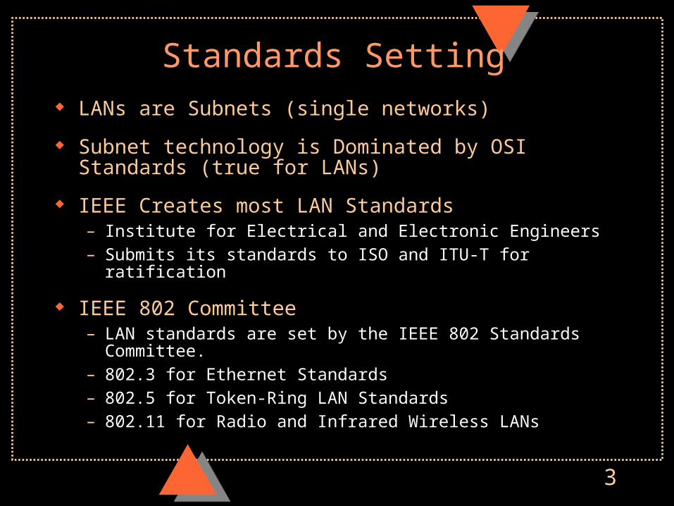
Standards Setting LANs are Subnets (single networks)
Subnet technology is Dominated by OSI Standards (true for LANs)
IEEE Creates most LAN Standards– Institute for Electrical and Electronic Engineers– Submits its standards to ISO and ITU-T for ratification
IEEE 802 Committee– LAN standards are set by the IEEE 802 Standards Committee. – 802.3 for Ethernet Standards– 802.5 for Token-Ring LAN Standards– 802.11 for Radio and Infrared Wireless LANs

4
LANs and OSI Architecture
OSI is a 7-layer architecture
LAN transmission only uses Layers 1 and 2
Layer 1: Physical Layer– Connectors, Media, Electrical signaling
Layer 2: Data Link Layer– Packaging data into frames– Managing transmission over link (error handling, etc.)– Access control: when each station may transmit

5
OSI Physical and Data Link Layers
F4-1
StationA
StationA
StationB
StationB
ConnectorPlug
ConnectorPlug
Transmission Medium(telephone wire, etc.)
Electrical Signal
Physical Layer (OSI Layer 1)Physical (plugs, media, etc.); Electrical (voltages, timing, etc.)
6
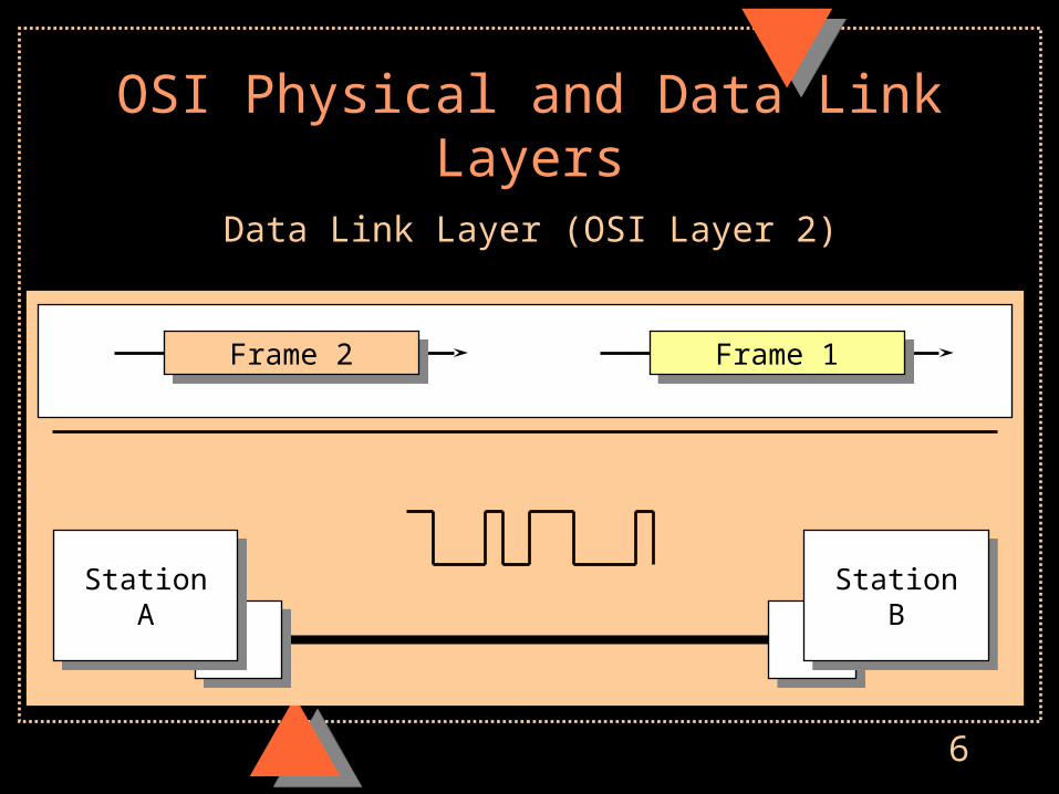
OSI Physical and Data Link Layers
Data Link Layer (OSI Layer 2)
Frame 2Frame 2 Frame 1Frame 1
StationA
StationA
StationB
StationB
7
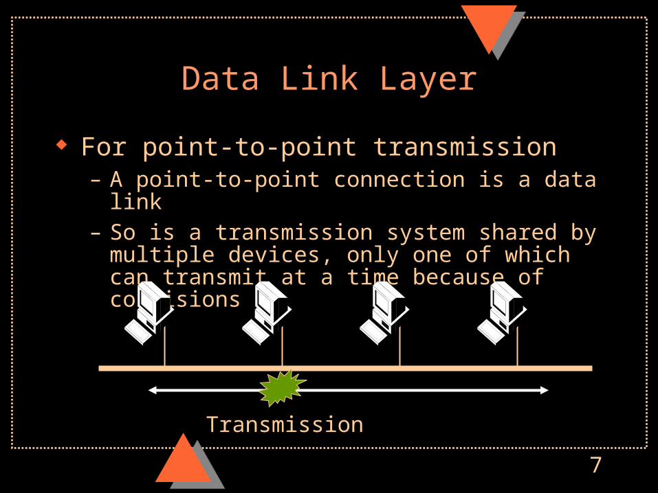
Data Link Layer
For point-to-point transmission– A point-to-point connection is a data link– So is a transmission system shared by multiple devices,
only one of which can transmit at a time because of collisions
Transmission

8
Data Link Layer
First function: Packaging of Data (1s and 0s)– PDU at Data Link Layer
is called a frame
Second Function: Access Control
– Only one station can transmit at any time
– If another transmitted, their signals would scramble one another
– Must control access to (transmission into) the transmission medium
9
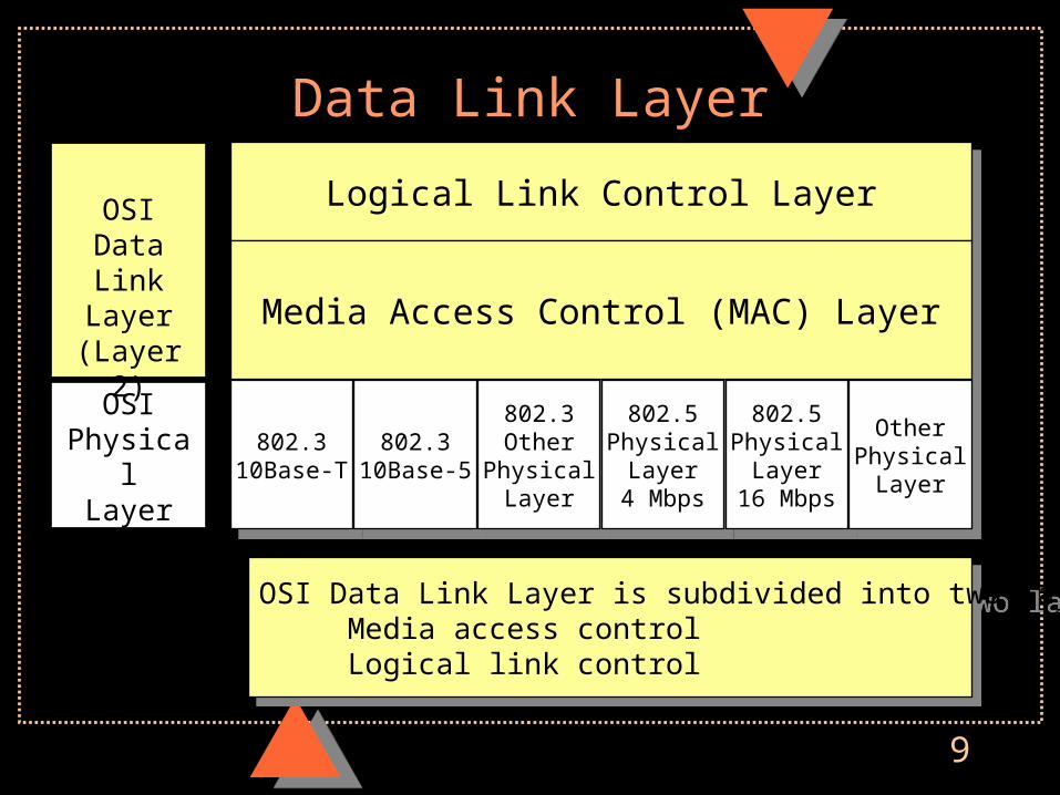
Data Link Layer
Logical Link Control LayerLogical Link Control Layer
Media Access Control (MAC) LayerMedia Access Control (MAC) Layer
802.310Base-T
802.310Base-T
802.310Base-5
802.310Base-5
802.3Other
PhysicalLayer
802.3Other
PhysicalLayer
802.5Physical
Layer4 Mbps
802.5Physical
Layer4 Mbps
802.5Physical
Layer16 Mbps
802.5Physical
Layer16 Mbps
OtherPhysical
Layer
OtherPhysical
Layer
OSIData Link
Layer(Layer 2)
OSIPhysical
Layer(Layer 1)
OSI Data Link Layer is subdivided into two layers Media access control Logical link control
OSI Data Link Layer is subdivided into two layers Media access control Logical link control

10
Media Access Control (MAC) LayerMedia Access Control (MAC) Layer
OSIPhysical(Layer 1)
MediaAccessControl
MAC Layer
802.310Base-T
802.310Base-T
802.310Base-5
802.310Base-5
802.3Other
PhysicalLayer
802.3Other
PhysicalLayer
802.5Physical
Layer4 Mbps
802.5Physical
Layer4 Mbps
802.5Physical
Layer16 Mbps
802.5Physical
Layer16 Mbps
OtherPhysical
Layer
OtherPhysical
Layer
MAC layer implements media access control: When a station may transmit Controls the framing of data along the wire
MAC layer implements media access control: When a station may transmit Controls the framing of data along the wire

11
OSIPhysical(Layer 1)
LLC
Logical Link Control Layer
802.2 Logical Link Control Layer802.2 Logical Link Control Layer
802.3 Media Access Control(MAC Layer)
802.3 Media Access Control(MAC Layer)
802.5MAC
4 Mbps
802.5MAC
4 Mbps
802.5MAC
16 Mbps
802.5MAC
16 Mbps
OtherMAC
OtherMAC
802.310Base-T
802.310Base-T
802.310Base-5
802.310Base-5
802.3Other
PhysicalLayer
802.3Other
PhysicalLayer
802.5Physical
Layer4 Mbps
802.5Physical
Layer4 Mbps
802.5Physical
Layer16 Mbps
802.5Physical
Layer16 Mbps
OtherPhysical
Layer
OtherPhysical
Layer
Provides Control Function Begin/end connections between stations Error correction (optional)
Provides Control Function Begin/end connections between stations Error correction (optional)
12
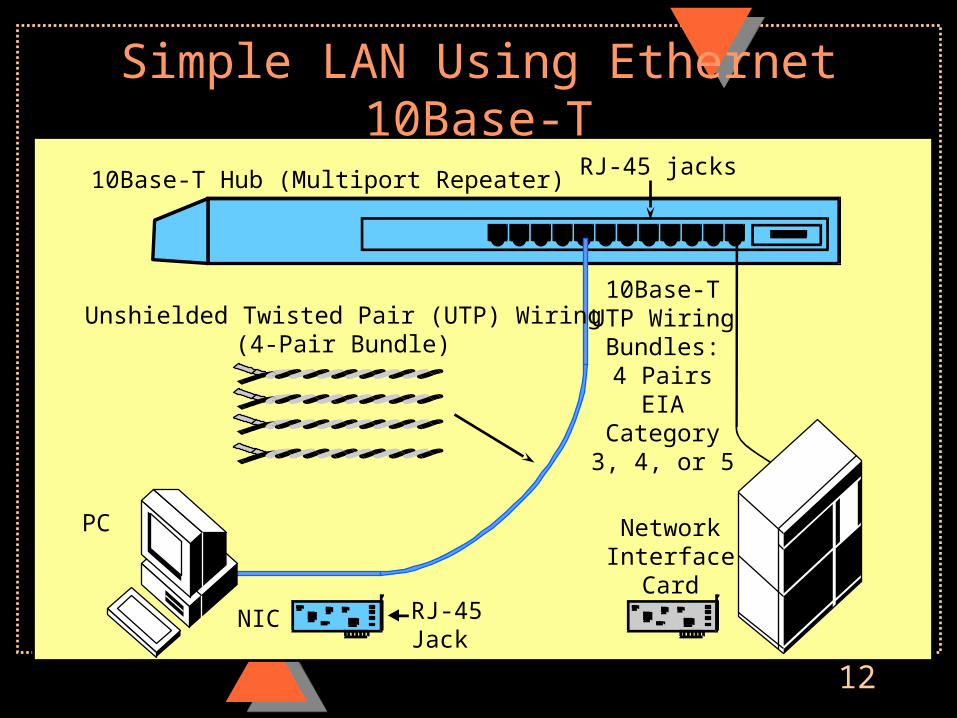
Simple LAN Using Ethernet 10Base-T
RJ-45 jacks10Base-T Hub (Multiport Repeater)
Unshielded Twisted Pair (UTP) Wiring(4-Pair Bundle)
PC
RJ-45Jack
NIC
NetworkInterface
Card
10Base-TUTP Wiring
Bundles:4 Pairs
EIACategory3, 4, or 5

13
Ethernet 10Base-T (802.3u)
Physical Layer Standard– 10 Mbps (10 in 10Base-T)– Baseband signaling: Injects voltage changes directly
into the wires (Base in 10Base-T)
Hubs (Multiport Repeaters)– Connect the stations together
10Base-T Hub
14
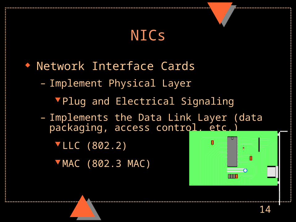
NICs
Network Interface Cards
– Implement Physical Layer
Plug and Electrical Signaling
– Implements the Data Link Layer (data packaging, access control, etc.)
LLC (802.2)
MAC (802.3 MAC)
15
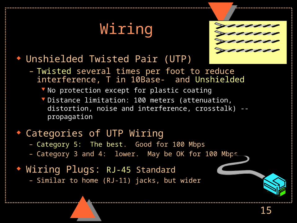
Wiring
Unshielded Twisted Pair (UTP)– Twisted several times per foot to reduce interference, T in
10Base- and Unshielded No protection except for plastic coating Distance limitation: 100 meters (attenuation, distortion, noise and
interference, crosstalk) -- propagation
Categories of UTP Wiring– Category 5: The best. Good for 100 Mbps– Category 3 and 4: lower. May be OK for 100 Mbps
Wiring Plugs: RJ-45 Standard– Similar to home (RJ-11) jacks, but wider

16
Attenuation
As signal travels, gets weaker– If too weak, cannot tell 1s and 0s
Distance
17
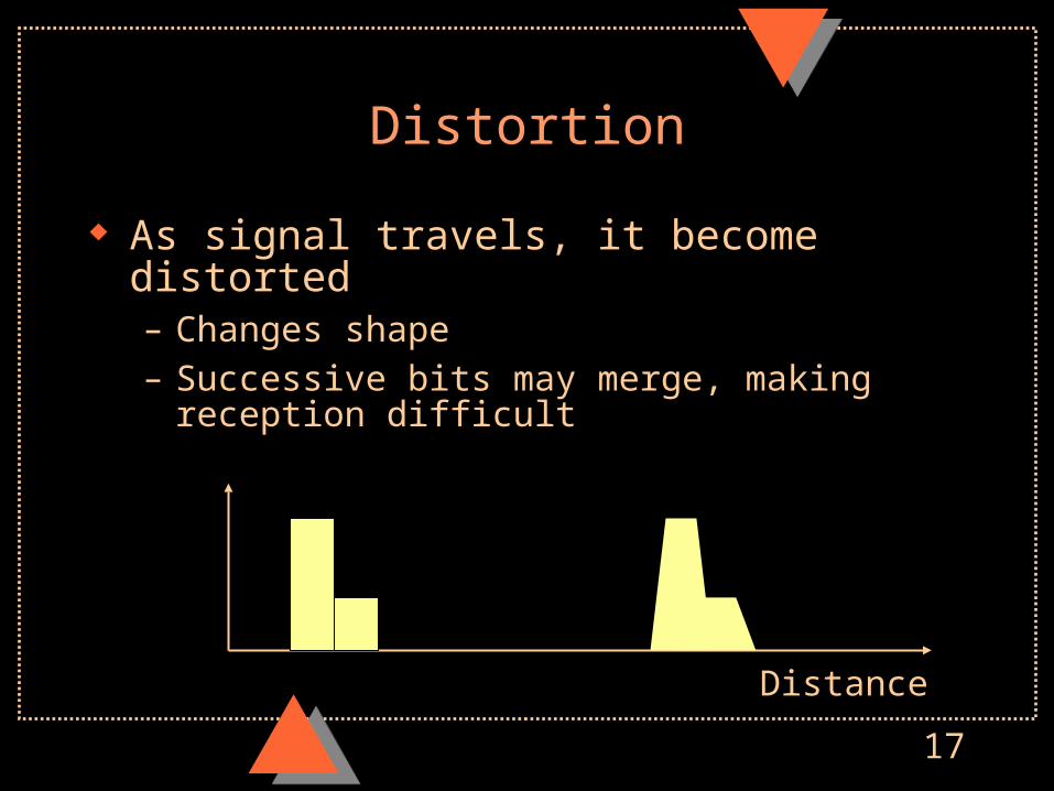
Distortion
As signal travels, it become distorted– Changes shape– Successive bits may merge, making reception difficult
Distance
18
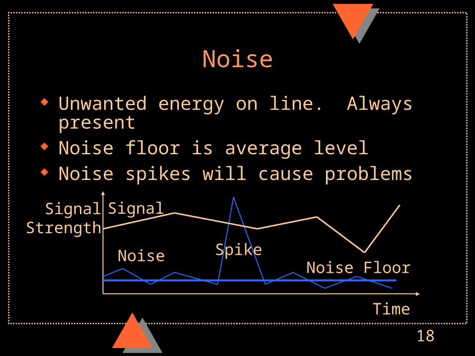
Noise
Unwanted energy on line. Always present Noise floor is average level Noise spikes will cause problems
SignalStrength
Time
Signal
Noise SpikeNoise Floor
19
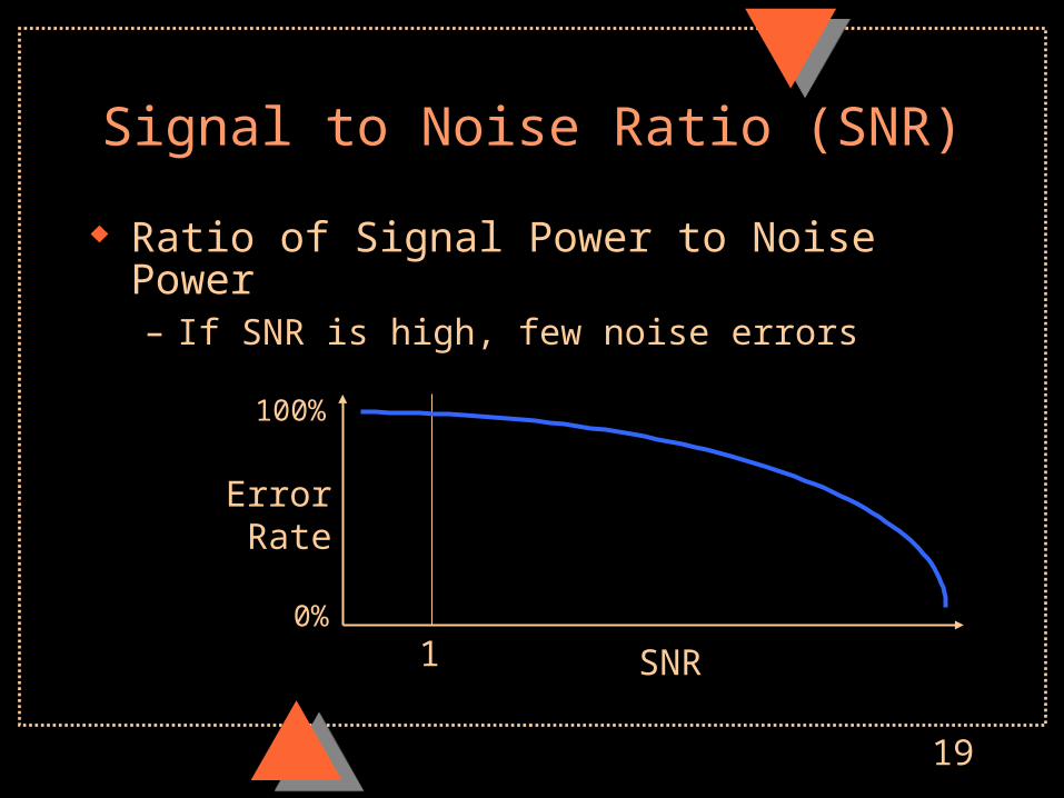
Signal to Noise Ratio (SNR)
Ratio of Signal Power to Noise Power– If SNR is high, few noise errors
SNR
ErrorRate
100%
0%1

20
Interference
Unwanted signal from outside sources– Often intermittent, difficult to diagnose
SignalStrength
Signal
Interference
21
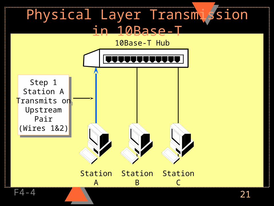
Physical Layer Transmission in 10Base-T
F4-4
10Base-T Hub
Step 1Station A
Transmits onUpstream
Pair(Wires 1&2)
Step 1Station A
Transmits onUpstream
Pair(Wires 1&2)
StationA
StationB
StationC

22
Physical Layer Transmission in 10Base-T10Base-T Hub
Step 2Hub Repeats(Broadcasts)The Message
To AllStations
On DownstreamPairs
(Wires 3&6)
Step 2Hub Repeats(Broadcasts)The Message
To AllStations
On DownstreamPairs
(Wires 3&6)
StationA
StationB
StationC
Bus transmission means broadcasting
23
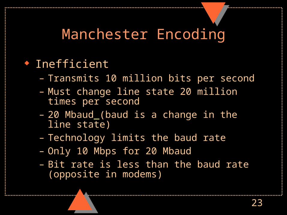
Manchester Encoding
Inefficient– Transmits 10 million bits per second– Must change line state 20 million times per second– 20 Mbaud (baud is a change in the line state)– Technology limits the baud rate– Only 10 Mbps for 20 Mbaud– Bit rate is less than the baud rate (opposite in modems)

24
MAC LayerCSMA/CD Media Access Control
Controls when stations may transmit– If two transmit at once, signals will be scrambled
Collision
X
Collisions will grow rapidly above 30% of line utilization. Keep traffic moderate, or throughput will be affected.

25
CSMA/CD Media Access Control
CS: Carrier Sense– Each NIC always listens for traffic on the line– This lets it recognize messages sent to its address– This also lets it know if the line is free
CSMA: Carrier Sense Media Access– A station may transmit if it hears no traffic on the
network

26
CSMA/CD Media Access Control in Ethernet
Station Ais Transmitting
Station Bmust wait
Station Ais Transmitting
Station Bmust wait
10Base-T Hub
StationA
StationB
StationC
MustWait
27
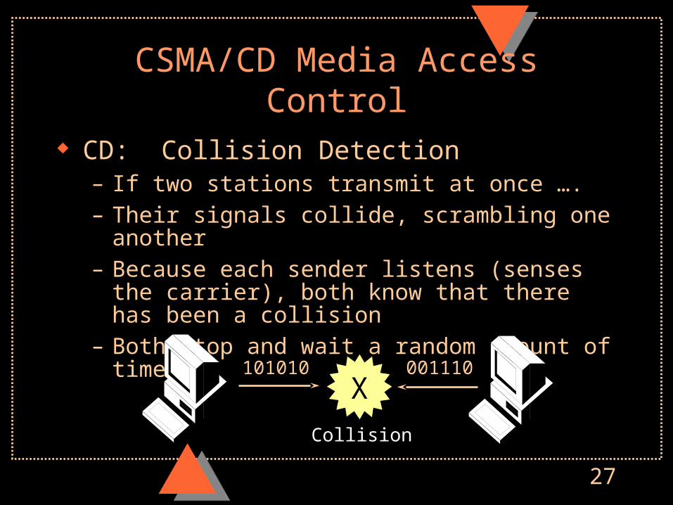
CSMA/CD Media Access Control
CD: Collision Detection– If two stations transmit at once ….– Their signals collide, scrambling one another– Because each sender listens (senses the carrier), both
know that there has been a collision– Both stop and wait a random amount of time.
X
Collision
101010 001110
28
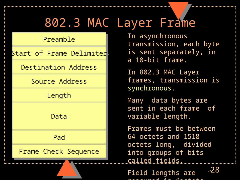
802.3 MAC Layer Frame
PreamblePreamble
Start of Frame DelimiterStart of Frame Delimiter
Destination AddressDestination Address
Source AddressSource Address
LengthLength
DataData
PadPad
Frame Check SequenceFrame Check Sequence
In asynchronous transmission, each byte is sent separately, in a 10-bit frame.
In 802.3 MAC Layer frames, transmission is synchronous.
Many data bytes are sent in each frame of variable length.
Frames must be between 64 octets and 1518 octets long, divided into groups of bits called fields.
Field lengths are measured in “octets”, eight bits.
“Octet” is a synonym for “byte”
29
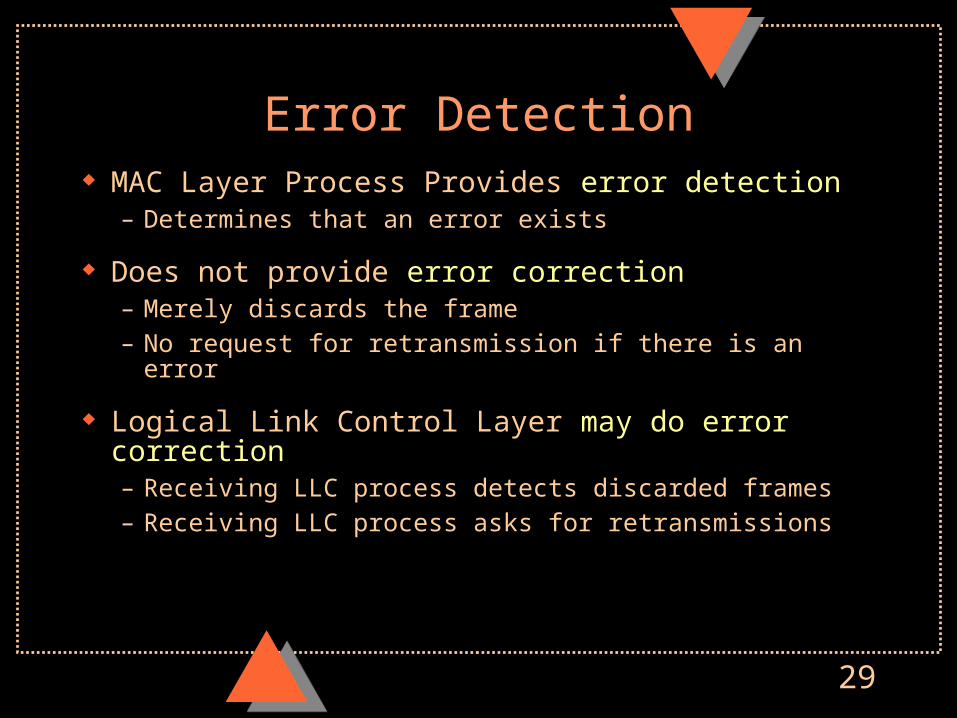
Error Detection MAC Layer Process Provides error detection
– Determines that an error exists
Does not provide error correction– Merely discards the frame– No request for retransmission if there is an error
Logical Link Control Layer may do error correction– Receiving LLC process detects discarded frames– Receiving LLC process asks for retransmissions
30
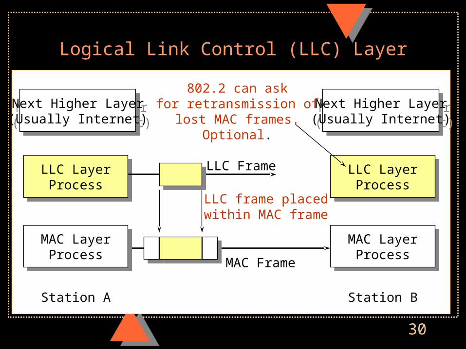
Logical Link Control (LLC) Layer
Next Higher Layer(Usually Internet)
Next Higher Layer(Usually Internet)
LLC LayerProcess
LLC LayerProcess
MAC LayerProcess
MAC LayerProcess
Station A
Next Higher Layer(Usually Internet)
Next Higher Layer(Usually Internet)
LLC LayerProcess
LLC LayerProcess
MAC LayerProcess
MAC LayerProcess
Station B
LLC Frame
MAC Frame
802.2 can askfor retransmission of
lost MAC frames.Optional.
LLC frame placedwithin MAC frame
31
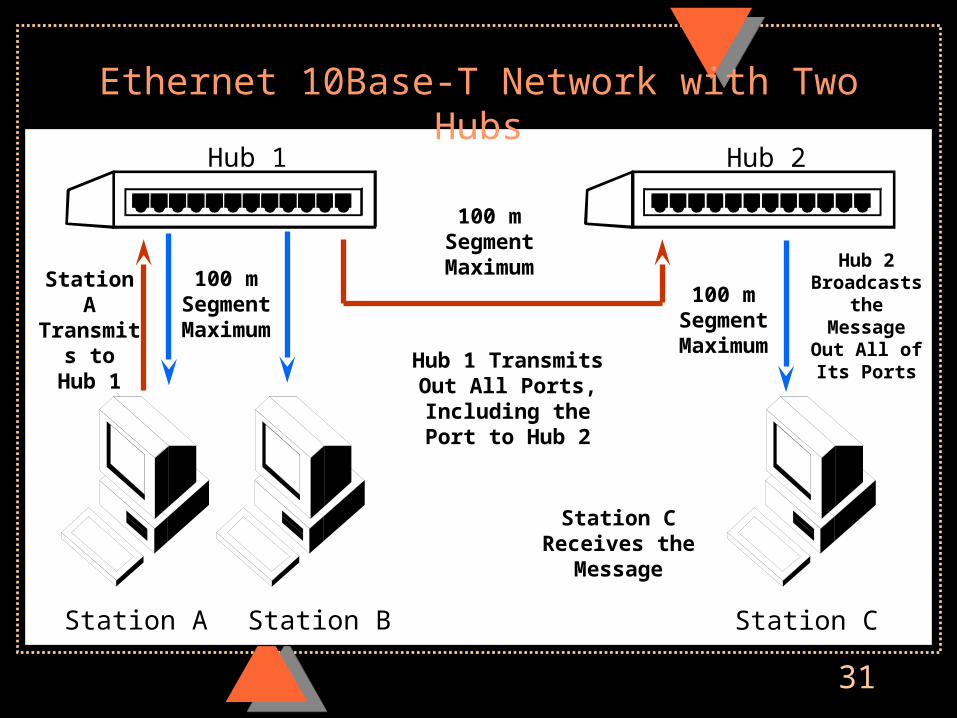
Ethernet 10Base-T Network with Two HubsHub 1 Hub 2
Station A Station B Station C
Station ATransmits
toHub 1 Hub 1 Transmits
Out All Ports,Including thePort to Hub 2
Hub 2 Broadcaststhe MessageOut All of Its
Ports
Station CReceives the
Message
100 mSegmentMaximum
100 mSegmentMaximum
100 mSegmentMaximum
32
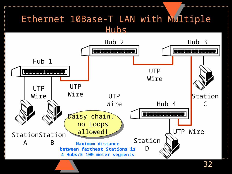
Ethernet 10Base-T LAN with Multiple Hubs
Hub 1
Hub 2 Hub 3
Hub 4
StationA
StationB
StationC
StationD
UTPWire
UTPWire UTP
Wire
UTPWire
UTP Wire
Daisy chain, no Loopsallowed!
Daisy chain, no Loopsallowed!
Maximum distancebetween farthest Stations is
4 Hubs/5 100 meter segments
33
Speed and Distance
Transmission speed worsens problems
– Error rates increase because bit periods are smaller and are more likely to be damaged by brief noise spikes and interference
– High speeds create high-frequency components in the signal that attenuate more rapidly than lower-frequency components
– In general, as speed increases, maximum distance decreases, although improving technology can lessen the decrease
34
Dealing with Propagation Effects
Use High-Quality, High-Cost Media– Use media designed for long-distance propagation– Optical fiber, coaxial cable– Too expensive for runs to many desktops, good for hub-
to-hub
Use Inexpensive Media to the Desktop– Improve the technology (allows 100 Mbps+ on UTP)– Accept distance limitations (100 meters for UTP)– More popular alternative to desktop because of low cost

35
Other Ethernet Physical Layer Standards
100Base-X– 100 Mbps– 100Base-TX uses Cat 5 UTP to desktop
1000Base-X– Gigabit Ethernet
Traditional Ethernet (before 10Base-T)– 10Base5– 10Base2

36
10Base5
Original Ethernet with slight changes
Thick coaxial cables
No hubs
Drop cables from stations to trunk cable
500 Meters maximum per segment
Maximum 5 segments between farthest stations
So maximum distance is 2500 meters
10Base5Trunk
Cable Segment
Drop Cable
37
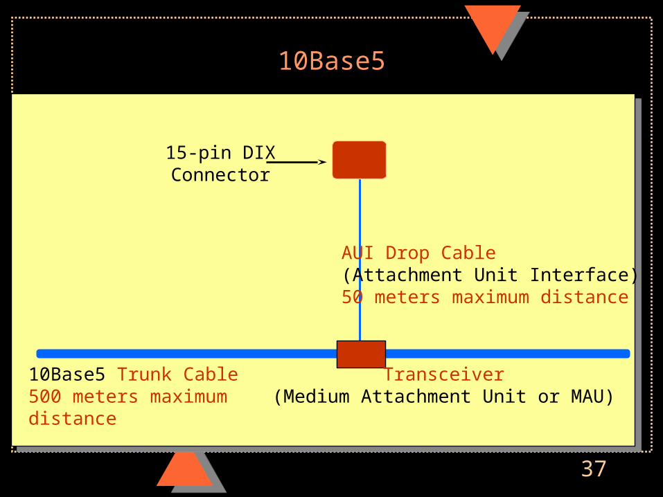
10Base5
15-pin DIXConnector
AUI Drop Cable(Attachment Unit Interface)50 meters maximum distance
10Base5 Trunk Cable500 meters maximumdistance
Transceiver(Medium Attachment Unit or MAU)

38
10Base5 Segments
Runs of trunk cable– 500 meters per segment (the 5 in 10Base5)
Repeaters– Connect trunk cable segments– Up to 5 segments between farthest two stations– 2500 meters maximum distance
39
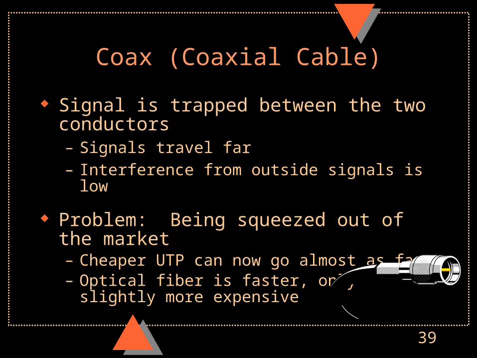
Coax (Coaxial Cable)
Signal is trapped between the two conductors– Signals travel far– Interference from outside signals is low
Problem: Being squeezed out of the market– Cheaper UTP can now go almost as fast– Optical fiber is faster, only slightly more expensive
40
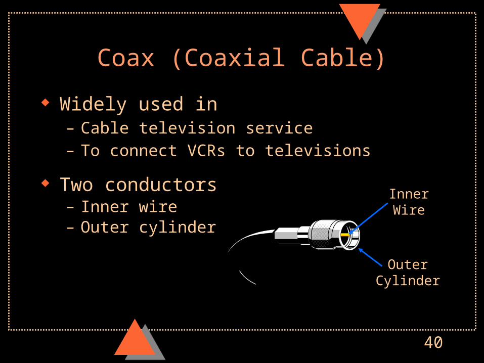
Coax (Coaxial Cable)
Widely used in– Cable television service– To connect VCRs to televisions
Two conductors– Inner wire– Outer cylinder
InnerWire
OuterCylinder

41
Co-Axial Cable
Insulation
OuterConductor(cylinder)
Insulation
InnerConductor
(wire)
42
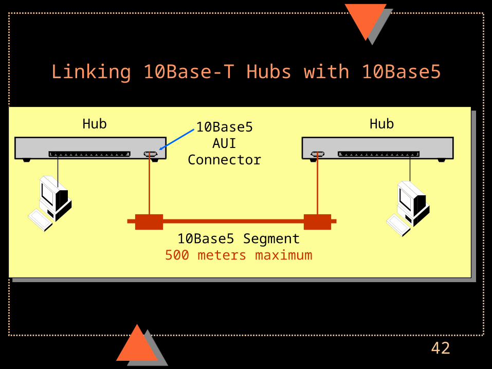
Linking 10Base-T Hubs with 10Base5
10Base5 Segment500 meters maximum
Hub Hub10Base5AUI
Connector
43
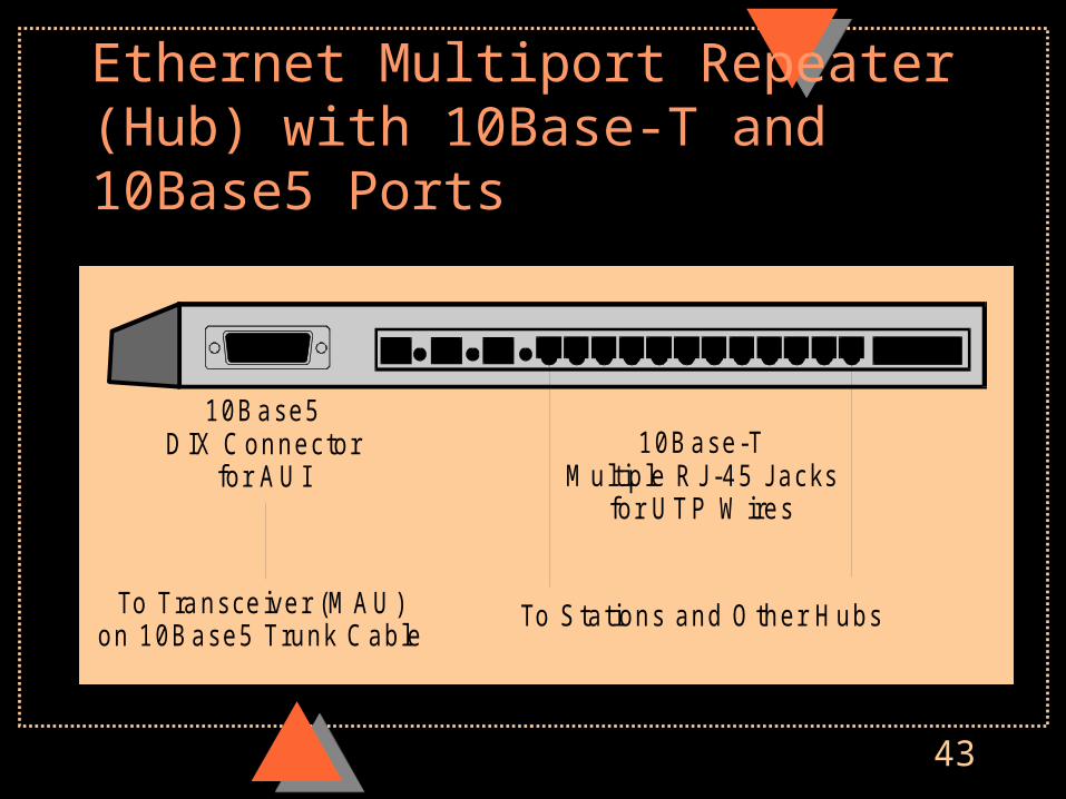
Ethernet Multiport Repeater (Hub) with 10Base-T and 10Base5 Ports
10Base5DIX Connector
for AUI10Base-T
Multiple RJ-45 Jacksfor UTP W ires
To Stations and Other HubsTo Transceiver (MAU)on 10Base5 Trunk Cable
44
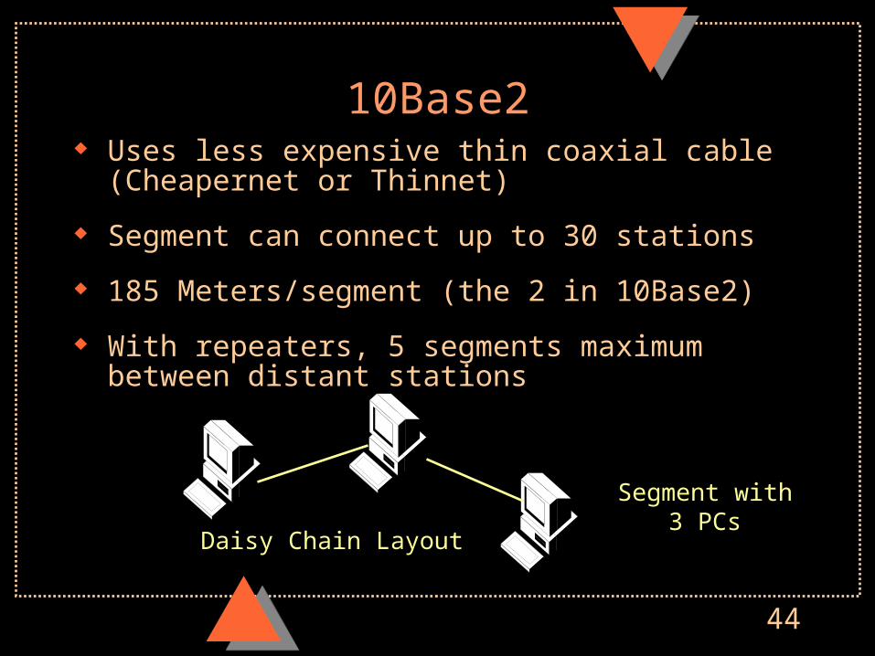
10Base2 Uses less expensive thin coaxial cable (Cheapernet or
Thinnet)
Segment can connect up to 30 stations
185 Meters/segment (the 2 in 10Base2)
With repeaters, 5 segments maximum between distant stations
Segment with3 PCs
Daisy Chain Layout
45
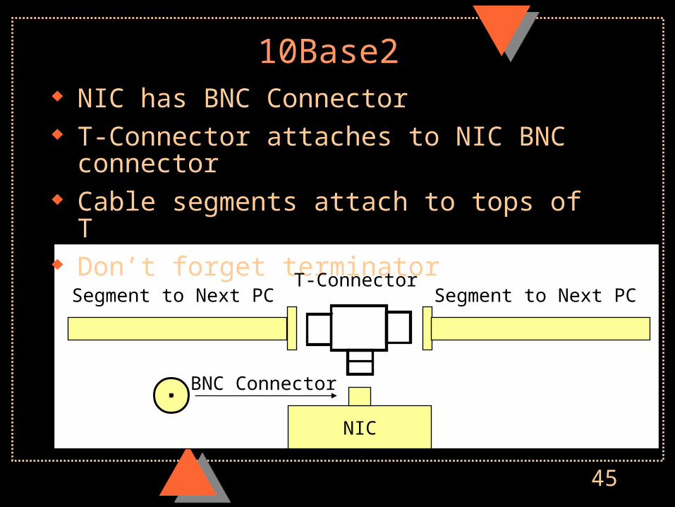
10Base2 NIC has BNC Connector T-Connector attaches to NIC BNC connector Cable segments attach to tops of T Don’t forget terminator
NIC
T-Connector
BNC Connector
Segment to Next PC Segment to Next PC
46
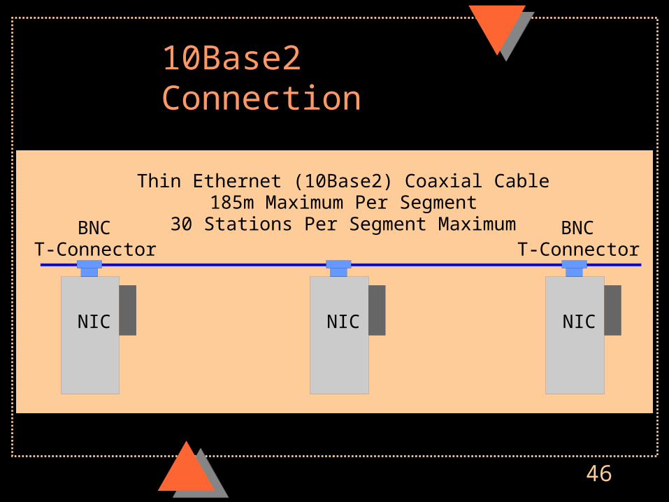
10Base2 Connection
NIC NIC NIC
Thin Ethernet (10Base2) Coaxial Cable185m Maximum Per Segment
30 Stations Per Segment MaximumBNCT-Connector
BNCT-Connector

47
Linking Hubs with 10Base2
10Base2 Segment
185 meters maximum
Hub Hub
10Base2BNC
Connector
48
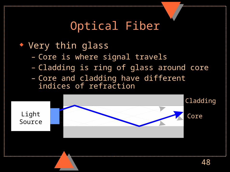
Optical Fiber
Very thin glass– Core is where signal travels– Cladding is ring of glass around core– Core and cladding have different indices of refraction
LightSource
Cladding
Core
49
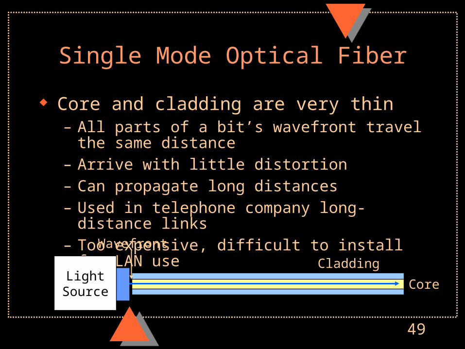
Single Mode Optical Fiber
Core and cladding are very thin– All parts of a bit’s wavefront travel the same distance– Arrive with little distortion– Can propagate long distances– Used in telephone company long-distance links– Too expensive, difficult to install for LAN use
Wavefront
LightSource Core
Cladding

50
Multimode Optical Fiber
Thick (usually around 62.5 micron core): easy to join
Different parts of wavefront travel different paths: limits distance before successive wavefronts overlap
Multimode is most common type in LANs
Step Index: core index of refraction is constant across core
LightSource
Cladding
Core

51
Multimode Optical Fiber Graded Index
– Index of refraction varies along core– Rays at different angles travel similar distances– Signals travel longer distances before distortion is bad– Multimode graded index fiber is dominant today
Core
Cladding
Light Source
52
10Base-F
Standard for connecting hubs
Can carry signals for 2,000 meters (2Km =~ 1.2 miles)
much farther and faster than 10Base5
53
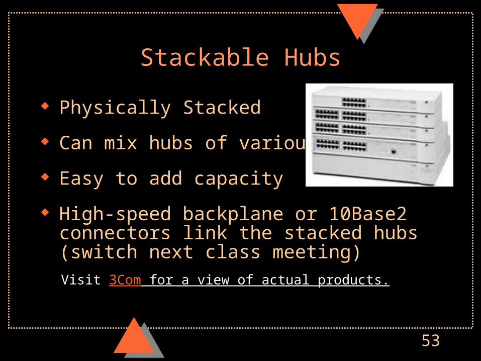
Stackable Hubs
Physically Stacked
Can mix hubs of various types
Easy to add capacity
High-speed backplane or 10Base2 connectors link the stacked hubs (switch next class meeting)
Visit 3Com for a view of actual products.
54
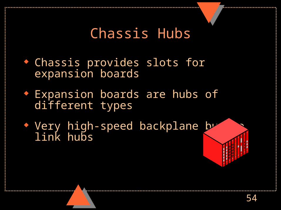
Chassis Hubs
Chassis provides slots for expansion boards
Expansion boards are hubs of different types
Very high-speed backplane bus to link hubs