1, 1 2 1,3 - unisi.it
21
robotics Article Design of Multiple Wearable Robotic Extra Fingers for Human Hand Augmentation Monica Malvezzi 1, *, Zubair Iqbal 1 , Maria Cristina Valigi 2 , Maria Pozzi 1,3 , Domenico Prattichizzo 1,3 and Gionata Salvietti 1,3 1 Department of Information Engineering and Mathematics, University of Siena, 53100 Siena, Italy; [email protected] (Z.I.); [email protected] (M.P.); [email protected] (D.P.); [email protected] (G.S.) 2 Department of Engineering, University of Perugia, Via G. Duranti, 1–06125 Perugia, Italy; [email protected] 3 Department of Advanced Robotics, Istituto Italiano di Tecnologia, 16163 Genoa, Italy * Correspondence: [email protected] Received: 4 November 2019; Accepted: 8 December 2019; Published: 11 December 2019 Abstract: Augmenting the human hand with robotic extra fingers is a cutting-edge research topic and has many potential applications, in particular as a compensatory and rehabilitation tool for patients with upper limb impairments. Devices composed of two extra fingers are preferred with respect to single finger devices when reliable grasps, resistance to external disturbances, and higher payloads are required. Underactuation and compliance are design choices that can reduce the device complexity and weight, maintaining the adaptability to different grasped objects. When only one motor is adopted to actuate multiple fingers, a differential mechanism is necessary to decouple finger movements and distribute forces. In this paper, the main features of a wearable device composed of two robotic extra fingers are described and analyzed in terms of kinematics, statics, and mechanical resistance. Each finger is composed of modular phalanges and is actuated with a single tendon. Interphalangeal joints include a passive elastic element that allows restoring the initial reference configuration when the tendon is released. The stiffness of each passive element can be customized in the manufacturing process and can be chosen according to a desired closure movement of the fingers. Another key aspect of the device is the differential system connecting the actuator to the fingers. Keywords: wearable robots; underactuated robots; robotic manipulation 1. Introduction 1.1. Robotic Hands Robotic hands have represented a challenge for designers and engineers for at least three decades [1] due to the complexity of grasping and manipulation tasks and device limits [2]. Although several interesting solutions have been presented in the literature, there are still open challenges. There are hands that have an anthropomorphic structure [3,4], and others that exploit underactuation and parallel kinematic structures to gain adaptability to the grasped objects [5]. Applications range from humanoids [3,6], to prostheses [7], to space applications [5]. Different types of actuations have been implemented, not limited to electro-mechanic transmissions. In [8], for instance, pneumatic systems are adopted, while in [9], Shape Memory Alloy were used. Underactuation [10–12] and modularity [13] are aspects that are investigated to reduce the complexity of the hand by maintaining a suitable level of performance. Also, transmission systems have a great importance in robotic hands, as described in [14], where different transmission systems are compared for different robotic hands. Tendon-driven Robotics 2019, 8, 102; doi:10.3390/robotics8040102 www.mdpi.com/journal/robotics
Transcript of 1, 1 2 1,3 - unisi.it

robotics
Article
Design of Multiple Wearable Robotic Extra Fingersfor Human Hand Augmentation
Monica Malvezzi 1,*, Zubair Iqbal 1, Maria Cristina Valigi 2 , Maria Pozzi 1,3 ,Domenico Prattichizzo 1,3 and Gionata Salvietti 1,3
1 Department of Information Engineering and Mathematics, University of Siena, 53100 Siena, Italy;[email protected] (Z.I.); [email protected] (M.P.); [email protected] (D.P.);[email protected] (G.S.)
2 Department of Engineering, University of Perugia, Via G. Duranti, 1–06125 Perugia, Italy;[email protected]
3 Department of Advanced Robotics, Istituto Italiano di Tecnologia, 16163 Genoa, Italy* Correspondence: [email protected]
Received: 4 November 2019; Accepted: 8 December 2019; Published: 11 December 2019�����������������
Abstract: Augmenting the human hand with robotic extra fingers is a cutting-edge research topicand has many potential applications, in particular as a compensatory and rehabilitation tool forpatients with upper limb impairments. Devices composed of two extra fingers are preferred withrespect to single finger devices when reliable grasps, resistance to external disturbances, and higherpayloads are required. Underactuation and compliance are design choices that can reduce the devicecomplexity and weight, maintaining the adaptability to different grasped objects. When only onemotor is adopted to actuate multiple fingers, a differential mechanism is necessary to decouple fingermovements and distribute forces. In this paper, the main features of a wearable device composed oftwo robotic extra fingers are described and analyzed in terms of kinematics, statics, and mechanicalresistance. Each finger is composed of modular phalanges and is actuated with a single tendon.Interphalangeal joints include a passive elastic element that allows restoring the initial referenceconfiguration when the tendon is released. The stiffness of each passive element can be customized inthe manufacturing process and can be chosen according to a desired closure movement of the fingers.Another key aspect of the device is the differential system connecting the actuator to the fingers.
Keywords: wearable robots; underactuated robots; robotic manipulation
1. Introduction
1.1. Robotic Hands
Robotic hands have represented a challenge for designers and engineers for at least threedecades [1] due to the complexity of grasping and manipulation tasks and device limits [2]. Althoughseveral interesting solutions have been presented in the literature, there are still open challenges. Thereare hands that have an anthropomorphic structure [3,4], and others that exploit underactuation andparallel kinematic structures to gain adaptability to the grasped objects [5]. Applications range fromhumanoids [3,6], to prostheses [7], to space applications [5]. Different types of actuations have beenimplemented, not limited to electro-mechanic transmissions. In [8], for instance, pneumatic systemsare adopted, while in [9], Shape Memory Alloy were used. Underactuation [10–12] and modularity [13]are aspects that are investigated to reduce the complexity of the hand by maintaining a suitable levelof performance. Also, transmission systems have a great importance in robotic hands, as describedin [14], where different transmission systems are compared for different robotic hands. Tendon-driven
Robotics 2019, 8, 102; doi:10.3390/robotics8040102 www.mdpi.com/journal/robotics

Robotics 2019, 8, 102 2 of 21
mechanisms have been widely used in articulated-finger robotic hands. In [15], several interestingissues on tendon-driven mechanisms are discussed, with a focus on tendon redundancy and jointstiffness adjustability for a robotic mechanism driven with redundant tendons.
1.2. Wearable Robotic Extra Fingers
More recently, a new branch in robotics research, involving both robotic hands and human-robotinteraction problems, was born: it is referred to as human augmentation and consists in developingwearable robotic systems that are supplementary with respect to human body structure [16,17].A particularly interesting application of wearable robotic extra limbs is introduced in [18]: the proposeddevice is a modular robotic extra finger that can be worn by a user as a bracelet and augments thehuman hand in terms of workspace and manipulation capabilities. An underactuated version of thisdevice has been introduced in [19] to assist patients with limited hand and arm functions for instanceafter a stroke event. Another implementation of wearable robotic extra fingers is presented in [20],in which a pair of soft robotic fingers driven by tendons and servomotors are worn on a human handand lay on the same plane of the palm, working as two additional thumbs. In applications in whichwearable extra fingers are used as compensatory devices, although the availability of a wearable roboticextra-finger opposed to the paretic limb allows the patient a stable hold for a large number of objects, asolution with two or multiple fingers could further help the user when performing some activitiesrequiring higher payloads and grasp stability [21].
1.3. Underactuation in Robotic Extra Fingers
Underactuation is an important aspect to be considered in designing safe and robust robotic handsand fingers. Reducing the number of actuators is particularly important in wearable devices, in whichthe weight and the complexity should be reduced as much as possible. In general, an underactuatedmechanism is defined as a mechanism that has fewer actuators than degrees of freedom. In robotichands, it is important to notice that underactuation can provide interesting properties to the device,like for instance self adaptability [22]. However, reducing the number of actuated degrees of freedom(DoFs) may decrease the overall manipulability properties and the capability to adapt to differentshapes and dimensions of grasped objects. For single-finger robotic devices, these properties can bepartially recovered by means of compliance, that in the wearable device introduced in [19] has beenimplemented by passive elastic elements in interphalangeal joints.
1.4. Differential Mechanisms
In devices composed of more than one finger, however, joint compliance is not enough to guaranteethe adaptability to the different shapes of grasped objects. If one motor is employed directly to drivesimultaneously the opening and closing motion of the fingers, when a finger is blocked, due to thecontact with an object or a surface, the other one will stop, too. A differential mechanism is thereforenecessary in devices composed of multiple fingers actuated with a single motor. For a double roboticextra finger, that is a device with two outputs and one input, a simple differential mechanism canbe used to decouple finger motions when one of them is constrained. In general, a differential is amechanism with two-degrees of freedom able to transform a single input into two outputs. The roleof the differential mechanism is to distribute an input force/torque Fa between two outputs, Fa
1 andFa
2, so that Fa = Fa1 + Fa
2. In the literature, there are many applications of differential mechanismsfor robotic fingers and hands [23]. In [24], a differential system based on gears is used for a novelarchitecture of robotic hand and the properties of differential mechanisms arranged in cascade viaparallel or serial connections is studied. In [25], a planetary gear solution and a fluid T-pipe scheme aredescribed. In [26], a moving pulley differential mechanism was used, while in [3] a differential with aT-shape fluid mechanism and the connected seesaw circuit is presented. In [27], an underactuatedanthropomorphic gripper for prosthetic applications was presented, in which a mechanical lever insidethe palm allowed to extend the grasping capabilities and improve the force transmission ratio of the

Robotics 2019, 8, 102 3 of 21
gripper. This mechanism was further developed in [28], in which the differential mechanism includeda set of locking buttons allowing the user to stop the motion of each finger.
1.5. Paper Contribution
In this paper, the main criteria that were followed to design a double robotic extra finger forcompensating and augmenting human hand abilities (Figure 1) are described. Differently from previousworks [19,21], all the mechanical components of the fingers were designed in a parametric way, tofurther exploit the modularity of the device and adapt it to different users and applications. A doublewearable robotic extra finger was preliminarily introduced in [29], however, in that device both fingerswere actuated with the same motor, using a single Y-shaped tendon that constrained fingers’ motions.This solution was an improvement with respect to a single finger, as it allowed to increase the graspingquality in terms of number of contacts, stability, and grasp stiffness. However, the wearable robotintroduced in [29] was not able to adapt to grasp objects with irregular shapes or multiple objects,due to the coupling between fingers generated by the single tendon. The problem can be solved byinserting a differential system between the actuator and the fingers, allowing to decouple their motions.In this paper, we analyze the requirements and main design aspects of the differential mechanism thatis necessary to guarantee the proper and decoupled closure movement of each of the two fingers.
Robotics 2019, 8, 102 3 of 21
differential mechanism included a set of locking buttons allowing the user to stop the motion of each
finger.
1.5. Paper Contribution
In this paper, the main criteria that were followed to design a double robotic extra finger for
compensating and augmenting human hand abilities (Figure 1) are described. Differently from
previous works [19,21], all the mechanical components of the fingers were designed in a parametric
way, to further exploit the modularity of the device and adapt it to different users and applications.
A double wearable robotic extra finger was preliminarily introduced in [29], however, in that device
both fingers were actuated with the same motor, using a single Y-shaped tendon that constrained
fingers’ motions. This solution was an improvement with respect to a single finger, as it allowed to
increase the grasping quality in terms of number of contacts, stability, and grasp stiffness. However,
the wearable robot introduced in [29] was not able to adapt to grasp objects with irregular shapes or
multiple objects, due to the coupling between fingers generated by the single tendon. The problem
can be solved by inserting a differential system between the actuator and the fingers, allowing to
decouple their motions. In this paper, we analyze the requirements and main design aspects of the
differential mechanism that is necessary to guarantee the proper and decoupled closure movement
of each of the two fingers.
(a) (b) (c)
Figure 1. The prototype of the device, consisting in two wearable extra fingers, worn by a user.
(a) Reference open configuration. (b) Closed configuration. (c) Example of how the differential
mechanism decouples the motion of the fingers, so that the device can adapt to different surfaces and
object shapes.
The device that is described in the following sections consists of two main parts: the support
base and the mobile part, composed of two modular robotic fingers actuated by means of two tendons
and a single motor. The end edge of each tendon is fixed on the distal module of the finger, while the
opposite side is fastened to an element sliding inside the differential box. Fingers are composed by
rigid phalanges connected by compliant interphalangeal joints, that can be approximated as simple
1-DoF revolute joints. When the motor actuates the differential by pulling the sliding element, both
tendons flex the fingers, that reach a configuration that is suitable for grasping objects (closed
configuration, Figure 1b), while when the torque of the motor is released, the passive elastic elements
in the joints restore the fingers to their initial extended configuration (reference open configuration,
Figure 1a).
The paper is organized as follows. After an overview of the finger structure (Section 2), a detailed
mechanical analysis of the device is given in Section 3 and a first prototype is described in Section 4.
Sections 5 and 6 draw the conclusions of the paper, summarizing envisaged applications of the
proposed wearable robotic device.
Figure 1. The prototype of the device, consisting in two wearable extra fingers, worn by a user.(a) Reference open configuration. (b) Closed configuration. (c) Example of how the differentialmechanism decouples the motion of the fingers, so that the device can adapt to different surfaces andobject shapes.
The device that is described in the following sections consists of two main parts: the support baseand the mobile part, composed of two modular robotic fingers actuated by means of two tendonsand a single motor. The end edge of each tendon is fixed on the distal module of the finger, while theopposite side is fastened to an element sliding inside the differential box. Fingers are composed by rigidphalanges connected by compliant interphalangeal joints, that can be approximated as simple 1-DoFrevolute joints. When the motor actuates the differential by pulling the sliding element, both tendonsflex the fingers, that reach a configuration that is suitable for grasping objects (closed configuration,Figure 1b), while when the torque of the motor is released, the passive elastic elements in the jointsrestore the fingers to their initial extended configuration (reference open configuration, Figure 1a).
The paper is organized as follows. After an overview of the finger structure (Section 2), a detailedmechanical analysis of the device is given in Section 3 and a first prototype is described in Section 4.Sections 5 and 6 draw the conclusions of the paper, summarizing envisaged applications of theproposed wearable robotic device.

Robotics 2019, 8, 102 4 of 21
2. Device Overview
Figure 1 shows the prototype of the double robotic extra finger presented in this work, constitutedby two fingers. Each finger has 7 modules, each of which has a part that can be approximately consideredrigid (white phalanges in Figure 1) and a part that is passively deformable (black interphalangeal jointsin Figure 1). Finger orientation with respect to the fixed support can be manually adapted by the useraccording to the specific task (see the video S1 in Supplementary Materials).
Rigid elements of the finger can be created with standard Fused Deposition Modelling (FDM)techniques and materials, as for instance Acrylonitrile Butadiene Styrene (ABS) or Polylactic Acid (PLA).For the deformable passive interphalangeal elements, a material that can undergo high deformationswhen subject to external forces is needed: for these elements, we employed Thermoplastic Polyurethane(TPU) [30], a plastic material that has this desirable mechanical property and can be also manufacturedwith standard FDM techniques. Furthermore, by changing some manufacturing parameters, as forinstance the infill density percentage or pattern, it is possible to modify mechanical properties of thecomponent. The main elements composing modular fingers, as detailed in Figure 2, are rigid elements(Figure 2a–c) and deformable elements (Figure 2d). Three different rigid elements have been designedfor the proximal (Figure 2a), intermediate (Figure 2b), and distal (Figure 2c) phalanges. The structureis modular and solutions with different numbers of phalanges can be easily realized. In this paper, weconsidered fingers composed of seven modules, since we verified that this value is an acceptable tradeoff to guarantee wearability and suitable grasp capability of several objects related to activities of dailyliving (ADL).
Robotics 2019, 8, 102 4 of 21
2. Device Overview
Figure 1 shows the prototype of the double robotic extra finger presented in this work,
constituted by two fingers. Each finger has 7 modules, each of which has a part that can be
approximately considered rigid (white phalanges in Figure 1) and a part that is passively deformable
(black interphalangeal joints in Figure 1). Finger orientation with respect to the fixed support can be
manually adapted by the user according to the specific task (see the video S1 in Supplementary
Materials).
Rigid elements of the finger can be created with standard Fused Deposition Modelling (FDM)
techniques and materials, as for instance Acrylonitrile Butadiene Styrene (ABS) or Polylactic Acid
(PLA). For the deformable passive interphalangeal elements, a material that can undergo high
deformations when subject to external forces is needed: for these elements, we employed
Thermoplastic Polyurethane (TPU) [30], a plastic material that has this desirable mechanical property
and can be also manufactured with standard FDM techniques. Furthermore, by changing some
manufacturing parameters, as for instance the infill density percentage or pattern, it is possible to
modify mechanical properties of the component. The main elements composing modular fingers, as
detailed in Figure 2, are rigid elements (Figure 2a–c) and deformable elements (Figure 2d). Three
different rigid elements have been designed for the proximal (Figure 2a), intermediate (Figure 2b),
and distal (Figure 2c) phalanges. The structure is modular and solutions with different numbers of
phalanges can be easily realized. In this paper, we considered fingers composed of seven modules,
since we verified that this value is an acceptable trade off to guarantee wearability and suitable grasp
capability of several objects related to activities of daily living (ADL).
(a) (b)
(c) (d)
Figure 2. Main components of the modular underactuated finger. (a) Proximal element connected to
finger base; (b) intermediate phalanx; (c) distal phalanx; (d) deformable interphalangeal element.
Each finger is actuated with a single tendon, connected on one side to the actuation and
transmission part, and on the other side to the distal phalanx. When the motor actuation pulls the
tendon, fingers close following a movement that depends on passive deformable element stiffness.
The next section presents the method followed for choosing the mechanical properties (stiffness) of
passive elements in interphalangeal joints to obtain a desired closure motion, and how it was applied
to different configurations of single and double extra fingers.
The motor and differential mechanism of the double extra finger are installed in a support fixed
on user’s forearm (Figure 1a), the overall encumbrance of the motor, differential, and tendon routing
Figure 2. Main components of the modular underactuated finger. (a) Proximal element connected tofinger base; (b) intermediate phalanx; (c) distal phalanx; (d) deformable interphalangeal element.
Each finger is actuated with a single tendon, connected on one side to the actuation andtransmission part, and on the other side to the distal phalanx. When the motor actuation pulls thetendon, fingers close following a movement that depends on passive deformable element stiffness.The next section presents the method followed for choosing the mechanical properties (stiffness) ofpassive elements in interphalangeal joints to obtain a desired closure motion, and how it was appliedto different configurations of single and double extra fingers.

Robotics 2019, 8, 102 5 of 21
The motor and differential mechanism of the double extra finger are installed in a support fixedon user’s forearm (Figure 1a), the overall encumbrance of the motor, differential, and tendon routingsystem is 130 × 50 × 40 mm. The size of this support can be customized and modelled accordingto user’s specific requirements. In particular, in future developments of this work we will use 3Dscanner techniques [31,32] to reconstruct user’s forearm geometry and to customize the design of thefixed support.
The motor, fixed at the base of the box, rotates the drive pulley. The first tendon connects themotor pulley to a sliding element. Two secondary tendons connect the pulleys of the sliding elementto the fingers and are fixed to their distal phalanges.
The main components of the device are shown in the CAD model represented in Figure 3 andare: A) the actuator, B) the drive pulley, C) the fixed pin necessary to provide a suitable directionto the tendon, D) the sliding element, E) two elements necessary to provide the right directions totendons connected to the fingers, F) the tendons, the finger modules, constituted by G) a rigid element,H) connected to a compliant element, J) through cylindrical guides.
Robotics 2019, 8, 102 5 of 21
system is 130 × 50 × 40 mm. The size of this support can be customized and modelled according to
user’s specific requirements. In particular, in future developments of this work we will use 3D
scanner techniques [31,32] to reconstruct user’s forearm geometry and to customize the design of the
fixed support.
The motor, fixed at the base of the box, rotates the drive pulley. The first tendon connects the
motor pulley to a sliding element. Two secondary tendons connect the pulleys of the sliding element
to the fingers and are fixed to their distal phalanges.
The main components of the device are shown in the CAD model represented in Figure 3 and
are: A) the actuator, B) the drive pulley, C) the fixed pin necessary to provide a suitable direction to
the tendon, D) the sliding element, E) two elements necessary to provide the right directions to
tendons connected to the fingers, F) the tendons, the finger modules, constituted by G) a rigid
element, H) connected to a compliant element, J) through cylindrical guides .
Assembling and de-assembling fingers to adapt them to specific needs or to substitute some of
the components is a task that does not need specific knowledge or skills, even if bi-manual operations
are required. If the device is used as a rehabilitation or compensation tool by a patient with upper
limb impairments limiting its functionality, this operation can be managed for instance by the
physiotherapist, a family member, a collaborator, etc. Referring to the elements sketched in Figure 3,
the needed operations are: i) disconnect the tendon (F) of the finger that needs to be adapted;
ii) de-assemble and re-assemble rigid/flexible elements (G,H) of the finger according to the new
configuration (flexible joint passive elements can be connected/disconnected to the rigid links by
sliding them along the cylindrical guides in the rigid links (J)); iii) if the number of phalanges has
been modified, also tendon length needs to be adapted; iv) re-connect the tendon to the distal phalanx
and to the differential sliding element, passing through the rigid links.
Figure 3. Main components of the device. Tendons are represented in green. A—actuator. B—drive
pulley. C—fixed pin necessary to provide a suitable direction to the tendon. D—Sliding element. E—
elements necessary to provide the right directions to finger tendons. F—Tendon. G—Rigid
interphalangeal element. H—Flexible joint element. J—cylindrical connection between rigid and
flexible elements.
3. Analysis
3.1. Design of Finger Passive Elements
As introduced in the previous section, each finger has a single tendon and then, when actuated,
can follow only one predefined closure motion. The characteristics of closure motion depend on both
geometrical properties of finger components and on the stiffness of the passive element in the
interphalangeal joints. When a pulling force is applied to the tendon, stiffer joints will bend less than
Figure 3. Main components of the device. Tendons are represented in green. A—actuator. B—drivepulley. C—fixed pin necessary to provide a suitable direction to the tendon. D—Sliding element.E—elements necessary to provide the right directions to finger tendons. F—Tendon. G—Rigidinterphalangeal element. H—Flexible joint element. J—cylindrical connection between rigid andflexible elements.
Assembling and de-assembling fingers to adapt them to specific needs or to substitute some ofthe components is a task that does not need specific knowledge or skills, even if bi-manual operationsare required. If the device is used as a rehabilitation or compensation tool by a patient with upper limbimpairments limiting its functionality, this operation can be managed for instance by the physiotherapist,a family member, a collaborator, etc. Referring to the elements sketched in Figure 3, the neededoperations are: i) disconnect the tendon (F) of the finger that needs to be adapted; ii) de-assemble andre-assemble rigid/flexible elements (G,H) of the finger according to the new configuration (flexible jointpassive elements can be connected/disconnected to the rigid links by sliding them along the cylindricalguides in the rigid links (J)); iii) if the number of phalanges has been modified, also tendon lengthneeds to be adapted; iv) re-connect the tendon to the distal phalanx and to the differential slidingelement, passing through the rigid links.

Robotics 2019, 8, 102 6 of 21
3. Analysis
3.1. Design of Finger Passive Elements
As introduced in the previous section, each finger has a single tendon and then, when actuated,can follow only one predefined closure motion. The characteristics of closure motion depend onboth geometrical properties of finger components and on the stiffness of the passive element in theinterphalangeal joints. When a pulling force is applied to the tendon, stiffer joints will bend lessthan softer ones. By properly regulating the stiffness of each of the passive elements, it is thereforepossible to shape the closure motion. As previously introduced, the modular structure of the fingerallows to easily add, remove, or substitute the passive interphalangeal elements, to adapt the finger todifferent applications.
The first step consists of choosing the closure motion that has to be followed by the extra finger.In this paper, we focus on a double extra finger device, however the procedure that we present is
general and can be adapted to any number of fingers. Let us indicate with r1des(z) = [x1des(z), y1des(z),z1des(z)]T and r2des(z) = [x2des(z), y2des(z), z2des(z)]T two vectors containing the desired trajectories offingertips, with respect to a reference frame {S0} fixed on fingers’ base. Fingertip coordinates aredefined as a function of the variable z, describing the “closure” (z = 0 for completely open fingers, z = 1for completely closed fingers). For the sake of compactness, let us also collect both finger trajectories ina unique vector [rdes (z)] = [[r1des(z)]T, [r2des(z)]T]T.
To let the extra fingers be able to grasp a wide range of objects, cooperating with the human hand,it is important to choose the most suitable finger closure movement. Different methods can be usedto define the desired trajectories rdes(z). In the simulations presented in the following we adopt theprocedure based on bio-artificial synergies proposed in [33]. The concept of bio-artificial synergieswas introduced in [34] to control wearable extra fingers. Synergies were derived, similarly to [35], byperforming the Principal Component Analysis (PCA) on a set of grasps performed by the human handaugmented by two robotic extra fingers. In this paper, we exploit the concept of synergies but we couldnot extract directly the augmented hand synergy as in [34], since the methodology therein proposedwas based on the analysis of a dataset of grasps, that is not available in the design phase of the device.Here we extend the idea of mapping human hand synergies introduced for the human hand in [35],based on the definition of a virtual object, that we presented in some previous works. The method tomap human hand first postural synergy to robotic extra fingers has been previously introduced in [33]and in [36]. The output of the mapping procedure are the fingertip trajectories that we want to obtainwhen actuating the robotic extra fingers.
We therefore choose a set of discrete samples for the variable z describing fingers’ closure motion,z = [z1, . . . , zNs], we indicate with zi, with i = 1, . . . , Ns the generic sample, so that z1 = 0 and zNs = 1.We indicate with q a vector containing all the rotations of interphalangeal joints and with q0 its valuecorresponding to the initial (completely open) configuration. The value of q at the generic configurationzi can be evaluated by means of a standard inverse kinematic procedure, in particular, in this work weadopted an approximated algorithm based on the Jacobian pseudo-inverse, so that:
qi = qi−1 + [J(qi−1)]#(rdes(zi) − rdes(zi−1)) (1)
where J(q) represent the Jacobian matrix of the fingers, relating joint rotation time derivatives tofingertip velocities, i.e.,
.r = J(q)
.q (2)
and # indicates its pseudo-inverse, i.e., [J]# = [J]T([J][J]T
)−1.
Indicating with ∆l is a vector collecting the variation of tendon lengths with respect to the initialreference configuration, choosing the closure motion means specifying the relationship:
q = q(∆l), (3)

Robotics 2019, 8, 102 7 of 21
assuming that no external forces, except the tendon force, are applied to the finger elements. In otherterms, in this phase we do not consider any contact between finger elements and an object or theenvironment. For the prototype that has been introduced in the previous section, q is a vector with14 elements (7 joints per finger), and ∆l is a vector with 2 elements (lengths of the tendons connected toeach finger). In general, in an underactuated system, such a relationship cannot be defined, however,in our case, it can be established since in the joints there are passive elastic elements. The evaluation ofthe relationship in Equation (3) is possible if the stiffness values of the passive elements are known,as detailed in [33].
As we introduced above, in an underactuated mechanism it is not possible to define the relationshipintroduced in Equation (3), but it is easy to define, by means of simple geometrical considerations, itsdual, i.e.,
∆l = Mq. (4)
It is interesting to notice that this relation can be approximated with a linear map, and the elementsof matrix M (whose dimension is 2 × 14 for the device introduced in Section 2) depend on fingergeometrical properties [15]. By applying the Principle of Virtual Works to the fingers, it is easy toshow that:
τ = MTf, (5)
where τ is a vector collecting joint stiffness values, while f is the tendon force vector. Since in each jointa passive element is present, from the static analysis of the finger, it results that
τ−Kq(q− q0
)= 0, (6)
where q0 indicates the reference joint configurations, i.e., the configuration corresponding to τ = 0, andKq is the stiffness matrix. Kq elements represent the stiffness of passive elements of the interphalangealjoints. Since these elements are realized with a material with a high flexibility, in general to describe itsoverall compliance, a 6× 6 matrix should be necessary. However, it is reasonable to neglect the linearterms (normal and shear deformations), while regarding the rotation elements, the bending stiffnesswith respect to an axis perpendicular to the finger closure plane is much lower than the value evaluatedin the lateral direction, and it is also higher than the torsional stiffness. It is therefore reasonable tomodel the passive element as a single DoF revolute joint, with an equivalent stiffness value kqi. MatrixKq is a diagonal matrix collecting all the kqi values.
Once the desired closure motion rdes(z) is defined, through the inverse kinematics algorithm inEquation (1) is possible to define the corresponding reference values for interphalangeal joint rotations,qr = qr(∆l), and therefore, from Equations (3)–(6) it is possible to find the stiffness matrix
Kq = Kq(qr, q0, f
). (7)
The second step of the procedure consists in the definition of the stiffness value that each passiveelement of finger joints has to assume so to realize the desired closure motion. For a more detaileddescription of the procedure, the reader can refer to [33].
In this paper, we report the results obtained by applying this procedure to three differentconfigurations of human hand and extra fingers. For the evaluation, we realized the mathematicalmodels of the hand augmented with the robotic extra fingers using SynGrasp [37], a Matlab toolbox forthe simulation of robotic hand grasping and manipulation, that can manage synergy-actuated and morein general underactuated structures. The human hand biologically has 27 DoF, in this study we adopteda model with 20 DoF, similar to the one described in [38], in which we neglected the carpometacarpal(CMC) articulation of index, middle, ring, and little fingers. We choose this simplified model becausewe could apply to it the quantitative results, in terms of bio-artificial synergies, evaluated in [35] andavailable in the Hand Corpus repository (https://www.handcorpus.org/) [39].

Robotics 2019, 8, 102 8 of 21
Figure 4a shows a link-joint representation of the kinematic structure of the hand augmented withtwo extra fingers, each extra finger is composed of seven modules. Figure 4b shows the augmentedhand configuration when the human fingers are actuated according to the first postural synergyevaluated in [35] and the motion of the robotic ones are evaluated with the mapping procedure reportedin [36].
Robotics 2019, 8, 102 8 of 21
(a) (b)
Figure 4. SynGrasp model of the human hand augmented with two robotic extra fingers. Black lines
represent rigid links, cylinders represent revolute joints. The human hand is modelled as a 20 degrees of
freedom (DoF) system, augmented fingers have a modular structure with seven elements. (a) Reference
initial configuration. (b) Configuration of the hand when the first synergy is activated, in an intermediate
configuration between the initial reference and the completely closed ones.
According to the procedure that we previously described, stiffness values of the passive elastic
interphalangeal elements of robotic fingers depend on the trajectory that is mapped, but also on the
structure of the robotic fingers, and on the force applied on the tendons by the motor. Table 1
summarizes stiffness values obtained with extra fingers composed of 7 modules, in the three
configurations, shown in Figure 5: single extra finger opposite to human hand palm (Figure 5a),
double configuration with two parallel fingers opposite to human hand palm (Figure 5b), double
configuration, with two opposite fingers, one close to human thumb and the other one close to the
little finger (Figure 5c). This last configuration has been considered in the analysis phase to verify the
effect of finger configuration on closure motion and of the corresponding joint stiffness values. As
previously introduced, the orientation of the fingers with respect to the hand can be manually
regulated by the user to adapt to different objects and tasks. A configuration similar to the one
described in Figure 5c is the one described in [20]. Values in Table 1 have been normalized with
respect to the stiffness of the proximal joint, in this way it is possible to compare single and double
finger configurations. Since the analyzed configurations are symmetric with respect to the hand, for
the sake of brevity in double finger configurations the results have been reported only for one of the
fingers. As it can be seen, single and double parallel configurations present similar stiffness values,
while the double opposite configuration presents some differences.
(a) (b) (c)
Figure 5. Configurations that we compared for the evaluation of passive joint stiffness with the
mapping procedure applied to the first human hand postural synergy. (a) Single finger, opposite to
Figure 4. SynGrasp model of the human hand augmented with two robotic extra fingers. Black linesrepresent rigid links, cylinders represent revolute joints. The human hand is modelled as a 20 degreesof freedom (DoF) system, augmented fingers have a modular structure with seven elements. (a)Reference initial configuration. (b) Configuration of the hand when the first synergy is activated, in anintermediate configuration between the initial reference and the completely closed ones.
According to the procedure that we previously described, stiffness values of the passive elasticinterphalangeal elements of robotic fingers depend on the trajectory that is mapped, but also on thestructure of the robotic fingers, and on the force applied on the tendons by the motor. Table 1 summarizesstiffness values obtained with extra fingers composed of 7 modules, in the three configurations, shownin Figure 5: single extra finger opposite to human hand palm (Figure 5a), double configuration withtwo parallel fingers opposite to human hand palm (Figure 5b), double configuration, with two oppositefingers, one close to human thumb and the other one close to the little finger (Figure 5c). This lastconfiguration has been considered in the analysis phase to verify the effect of finger configurationon closure motion and of the corresponding joint stiffness values. As previously introduced, theorientation of the fingers with respect to the hand can be manually regulated by the user to adapt todifferent objects and tasks. A configuration similar to the one described in Figure 5c is the one describedin [20]. Values in Table 1 have been normalized with respect to the stiffness of the proximal joint, in thisway it is possible to compare single and double finger configurations. Since the analyzed configurationsare symmetric with respect to the hand, for the sake of brevity in double finger configurations theresults have been reported only for one of the fingers. As it can be seen, single and double parallelconfigurations present similar stiffness values, while the double opposite configuration presentssome differences.

Robotics 2019, 8, 102 9 of 21
Robotics 2019, 8, 102 8 of 21
(a) (b)
Figure 4. SynGrasp model of the human hand augmented with two robotic extra fingers. Black lines
represent rigid links, cylinders represent revolute joints. The human hand is modelled as a 20 degrees of
freedom (DoF) system, augmented fingers have a modular structure with seven elements. (a) Reference
initial configuration. (b) Configuration of the hand when the first synergy is activated, in an intermediate
configuration between the initial reference and the completely closed ones.
According to the procedure that we previously described, stiffness values of the passive elastic
interphalangeal elements of robotic fingers depend on the trajectory that is mapped, but also on the
structure of the robotic fingers, and on the force applied on the tendons by the motor. Table 1
summarizes stiffness values obtained with extra fingers composed of 7 modules, in the three
configurations, shown in Figure 5: single extra finger opposite to human hand palm (Figure 5a),
double configuration with two parallel fingers opposite to human hand palm (Figure 5b), double
configuration, with two opposite fingers, one close to human thumb and the other one close to the
little finger (Figure 5c). This last configuration has been considered in the analysis phase to verify the
effect of finger configuration on closure motion and of the corresponding joint stiffness values. As
previously introduced, the orientation of the fingers with respect to the hand can be manually
regulated by the user to adapt to different objects and tasks. A configuration similar to the one
described in Figure 5c is the one described in [20]. Values in Table 1 have been normalized with
respect to the stiffness of the proximal joint, in this way it is possible to compare single and double
finger configurations. Since the analyzed configurations are symmetric with respect to the hand, for
the sake of brevity in double finger configurations the results have been reported only for one of the
fingers. As it can be seen, single and double parallel configurations present similar stiffness values,
while the double opposite configuration presents some differences.
(a) (b) (c)
Figure 5. Configurations that we compared for the evaluation of passive joint stiffness with the
mapping procedure applied to the first human hand postural synergy. (a) Single finger, opposite to Figure 5. Configurations that we compared for the evaluation of passive joint stiffness with the mappingprocedure applied to the first human hand postural synergy. (a) Single finger, opposite to human hand.(b) Double configuration, fingers opposite to human hand palm. (c) Double configurations, fingers arealigned with hand palm.
Table 1. Passive elements of interphalangeal joints, stiffness values normalized with respect to the first(proximal) element, evaluated for the three configurations shown in Figure 6.
Configuration k1/k1 k2/k1 k3/k1 k4/k1 k5/k1 k6/k1 k7/k1
Single (Figure 5a) 1.00 1.17 1.39 1.74 2.32 3.50 6.98Double, opposite to the palm (Figure 5b) 1.00 1.10 1.33 1.65 2.20 3.31 6.61
Double, aligned with the palm (Figure 5c) 1.00 1.43 1.71 2.14 2.85 4.28 8.57
Figure 6a shows, for one of the fingers of the configuration in Figure 5b, the stiffness values ofthe passive interphalangeal elements Kq, that have been evaluated on the basis of the motion that weimposed on the fingers, represented as a function of the variable z, describing finger closure, that forthis type of mapping is also related to synergy actuation [36] (z = 0 in the reference open configuration,z = 1 when the hand is closed).
It is interesting to notice that:
• Kq values vary for the different joints: their values determine the closure motion of the fingersand are defined on the basis of the mapping procedure proposed in [36] and in [33].
• Kq values vary as a function of hand configuration, however, for the motion that we selected, sucha variation is not very high.
To highlight the effect of joint stiffness values in the closure motion of the finger, in Figure 6b wesimulated, for one of the robotic extra fingers, the trajectory of the fingertips obtained with the variablestiffness values defined by the previously described procedure, exactly resembling the “ideal” desiredtrajectory, (blue curve), the one that we obtain if we consider, for each joint, the mean stiffness value(red curve), and the one that we would obtain if all the joints of the finger had the same stiffness value(magenta curve). As it can be seen, the difference between the blue curve and the red one is quitelimited, compatible with the precision required for this type of device (few millimeters), so consideringa stiffness value different for all the joints, but constant for each joint, does not introduce significantdifference between the closure motion that was planned and the one that can be obtained with theunderactuated finger. On the other hand, the difference between ideal fingertip trajectory and the oneobtained with the same joint stiffness for all the modules (in the simulation we assumed the meanstiffness value among all the joints) is very high.
Robotics 2019, 8, 102 10 of 21
Robotics 2019, 8, 102 9 of 21
human hand. (b) Double configuration, fingers opposite to human hand palm. (c) Double
configurations, fingers are aligned with hand palm.
Table 1. Passive elements of interphalangeal joints, stiffness values normalized with respect to the
first (proximal) element, evaluated for the three configurations shown in Figure 6.
Configuration k1/k1 k2/k1 k3/k1 k4/k1 k5/k1 k6/k1 k7/k1
Single (Figure 5a) 1.00 1.17 1.39 1.74 2.32 3.50 6.98
Double, opposite to the palm (Figure 5b) 1.00 1.10 1.33 1.65 2.20 3.31 6.61
Double, aligned with the palm (Figure 5c) 1.00 1.43 1.71 2.14 2.85 4.28 8.57
Figure 6a shows, for one of the fingers of the configuration in Figure 5b, the stiffness values of
the passive interphalangeal elements 𝐊𝑞, that have been evaluated on the basis of the motion that we
imposed on the fingers, represented as a function of the variable 𝑧, describing finger closure, that for
this type of mapping is also related to synergy actuation [36] ( 𝑧 = 0 in the reference open
configuration, 𝑧 = 1 when the hand is closed).
It is interesting to notice that:
𝐊𝑞values vary for the different joints: their values determine the closure motion of
the fingers and are defined on the basis of the mapping procedure proposed in [36]
and in [33].
𝐊𝑞values vary as a function of hand configuration, however, for the motion that we selected, such
a variation is not very high.
To highlight the effect of joint stiffness values in the closure motion of the finger, in Figure 6b
we simulated, for one of the robotic extra fingers, the trajectory of the fingertips obtained with the
variable stiffness values defined by the previously described procedure, exactly resembling the
“ideal” desired trajectory, (blue curve), the one that we obtain if we consider, for each joint, the mean
stiffness value (red curve), and the one that we would obtain if all the joints of the finger had the
same stiffness value (magenta curve). As it can be seen, the difference between the blue curve and
the red one is quite limited, compatible with the precision required for this type of device (few
millimeters), so considering a stiffness value different for all the joints, but constant for each joint,
does not introduce significant difference between the closure motion that was planned and the one
that can be obtained with the underactuated finger. On the other hand, the difference between ideal
fingertip trajectory and the one obtained with the same joint stiffness for all the modules (in the
simulation we assumed the mean stiffness value among all the joints) is very high.
(a) (b)
Figure 6. (a) Joint stiffness values for one of the extra fingers of the configuration in Figure 5b,
evaluated as a function of synergy activation. (b) For the same configuration, trajectories of one of the
fingertips, during a finger closure motion, projected on a plane. Different trajectories are obtained by
considering variable stiffness profile evaluated by means of the mapping procedure (blue curve), the
mean stiffness value (constant) for each joint (red curve), the mean stiffness value for all the joints
(magenta curve).
0 0.2 0.4 0.6 0.8 1 1.2
z
0
500
1000
1500
2000
2500
3000
3500K
q
(Nm
m/r
ad
)
k1
k2
k3
k4
k5
k6
k7
-80 -60 -40 -20 0 20 40 60
y (mm)
-100
-80
-60
-40
-20
0
20
z
(m
m)
Variable stiffness
Constant Stiffness
Constant Stiffness 1
Figure 6. (a) Joint stiffness values for one of the extra fingers of the configuration in Figure 5b, evaluatedas a function of synergy activation. (b) For the same configuration, trajectories of one of the fingertips,during a finger closure motion, projected on a plane. Different trajectories are obtained by consideringvariable stiffness profile evaluated by means of the mapping procedure (blue curve), the mean stiffnessvalue (constant) for each joint (red curve), the mean stiffness value for all the joints (magenta curve).
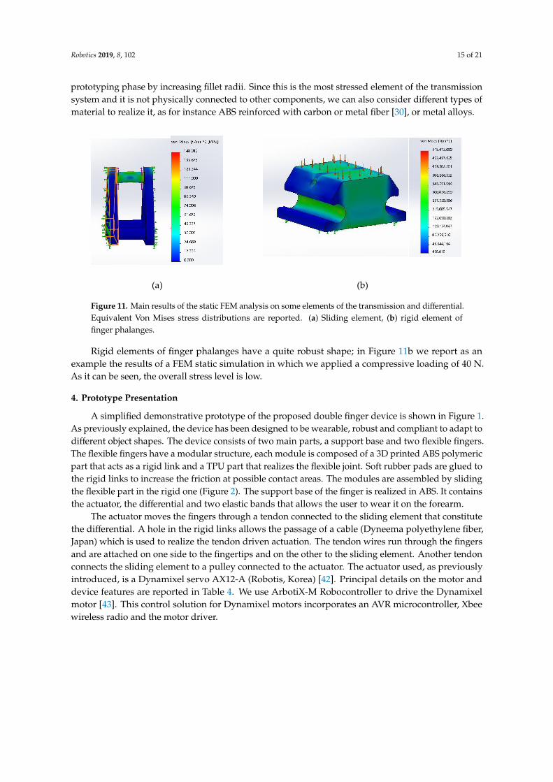
The third step consists in creating the passive elements so that their stiffness is the one calculatedin the previous phase. We analyzed the possibility of tuning finger joint stiffness values by exploitingthe potentialities of 3D printing fabrication methods, that are nowadays rapidly improving andoffering interesting opportunities. In particular, choosing a material as the Thermoplastic Polyurethane(TPU) for realizing the flexible parts, we can get different stiffness values, while maintaining thesame geometric shape, by regulating the percentage of infill density. This parameter affects primarilymaterial density, but also its mechanical properties [30]. As an example, Table 2 summarizes thevariation of Young’s modulus E of TPU as a function of the infill percentage density.
Table 2. Properties of Thermoplastic Polyurethane (TPU) as a function of infill density percentage.
Infill Density % E (MPa)
10 1.0730 1.3850 2.0770 6.5390 9.45
100 10.5
In a more general framework, the overall passive stiffness of a generic joint, indicated with k,depends mainly on joint geometry and material structural properties, and, considering a linear elasticbehavior, on Young’s modulus E, i.e.,:
k = k(d, E), (8)
where d is a vector containing all the parameters defining joint geometry (e.g., for a parallelepipedjoint, its length l, width w and thickness t). Young’s modulus E depends on material parameters andfabrication methods, i.e.,:
E = E(p1, p2, . . . , pn), (9)
where each value pi indicates one specific material property. In this work, we exploited the dependencyof k with respect to infill density percentage to define robotic finger properties. Future developmentsof this study will consider other manufacturing parameters, as for instance the infill pattern profile,and also composite materials.

Robotics 2019, 8, 102 11 of 21
3.2. Mechanical Transmission and Differential Mechanism Analysis
Concerning the differential system, the solution proposed in this paper to actuate a double extrafinger device for human hand augmentation is inspired by Dollar’s work on underactuated robotichands [40], using a moving pulley system; in Figure 7, a simplified and general scheme of this kind ofdifferential is presented [23].
Robotics 2019, 8, 102 10 of 21
The third step consists in creating the passive elements so that their stiffness is the one calculated
in the previous phase. We analyzed the possibility of tuning finger joint stiffness values by exploiting
the potentialities of 3D printing fabrication methods, that are nowadays rapidly improving and
offering interesting opportunities. In particular, choosing a material as the Thermoplastic
Polyurethane (TPU) for realizing the flexible parts, we can get different stiffness values, while
maintaining the same geometric shape, by regulating the percentage of infill density. This parameter
affects primarily material density, but also its mechanical properties [30]. As an example, Table 2
summarizes the variation of Young’s modulus E of TPU as a function of the infill percentage density.
Table 2. Properties of Thermoplastic Polyurethane (TPU) as a function of infill density percentage.
Infill Density % E (MPa)
10 1.07
30 1.38
50 2.07
70 6.53
90 9.45
100 10.5
In a more general framework, the overall passive stiffness of a generic joint, indicated with k,
depends mainly on joint geometry and material structural properties, and, considering a linear elastic
behavior, on Young’s modulus E, i.e.,:
k = k(d, E), (8)
where d is a vector containing all the parameters defining joint geometry (e.g., for a parallelepiped
joint, its length l, width w and thickness t). Young’s modulus E depends on material parameters and
fabrication methods, i.e.,:
E = E(p1, p2, …, pn), (9)
where each value pi indicates one specific material property. In this work, we exploited the
dependency of k with respect to infill density percentage to define robotic finger properties. Future
developments of this study will consider other manufacturing parameters, as for instance the infill
pattern profile, and also composite materials.
3.2. Mechanical Transmission and Differential Mechanism Analysis
Concerning the differential system, the solution proposed in this paper to actuate a double extra
finger device for human hand augmentation is inspired by Dollar’s work on underactuated robotic
hands [40], using a moving pulley system; in Figure 7, a simplified and general scheme of this kind
of differential is presented [23].
Figure 7. Simplified scheme of a typical differential mechanism with moving pulley.
The motivation for this choice is the compactness and excellent adaptability to the human’sforearm dimensions and, since the robotic fingers that are connected through the mechanism usetendons, the mobile pulley mechanism is the most effective system for force transmission. A spring isoften used to keep the two outputs in the same reference configuration when the system is not actuated,and the fingers are not externally constrained.
The pulley has 2 DoF: it can translate along a sliding guide (realizing a prismatic joint) and it canrotate around an axis perpendicular to the plane of the figure.
In this scheme, the input force is Fa and the output ones are Fa1 and Fa
2. The spring applies a torqueTs. In static equilibrium condition the following relationship holds:
F =[T f
]t∗ (10)
with
F =
[Fa
1Fa
2
]t∗ =
[FaTs
](11)
where the transformation matrix[T f
]is
[T f
]=
1c
[r sinα2
r − sinα1
](12)
where c is the sum of the distances of A1 and A2 points from the sliding guide (or prismatic joint)
c = r (sinα1 + sinα2) (13)
and α1 and α2 are the angles shown in Figure 6. If the stiffness of the spring is negligible, Equation (10)can be simplified as:
Fa1 = Fa
2 =Fa
sinα1 + sinα2(14)

Robotics 2019, 8, 102 12 of 21
An important property of this differential mechanism is that it is isotropic, and thus the twooutput forces are equal for any value of α1 and α2. The ratio Fa
i /Fa for i = 1,2 is influenced by α1 andα2, and c must be positive for a proper device working.
The distance between the pin and the sliding has to be at least equal to the maximum distancethat the pulley has to travel while both the fingers are completely closed from an initial extendedconfiguration. Let us consider one of the fingers and let us indicate with Θ the generic rotation betweenthe xn axis, defined on the distal phalanx of one finger and the reference direction x0 on the devicebase. Reference frames are defined so that Θ = 0 in the initial extended configuration, while Θ = Θc
in the configuration corresponding to complete finger closure. Let us indicate with ϑi the rotation ofthe i-th joint, so that
Θc =∑n
i=1ϑi (15)
To obtain the rotation ϑi the tendon is pulled by the motor and its length variation is indicatedwith ∆li (Figure 8). When the joint is rotated, the elastic element bends; indicating with l its lengthand assuming that after the deformation its profile is circular, its curvature radius can be evaluated asri =
lϑi
. The corresponding arc cord can be evaluated as:
ai = 2ri sin(ϑi2
)(16)
and tendon length variation is therefore (Figure 8)
∆li = l−ail(ri − h) = l− 2ri
(ri − h)ri
sin(ϑi
2
)(17)
Robotics 2019, 8, 102 12 of 21
Figure 8. Deformations of interphalangeal joints, scheme, and main geometrical parameters.
To close the fingers, it is necessary to vary the length of the tendon by ∆𝒍𝒕𝒐𝒕, that can be evaluated
as
∆𝑙𝑡𝑜𝑡 = ∑ ∆𝑙𝑖
n
1
(18)
Assuming 𝑙𝑖 = 17.3 𝑚𝑚 for all the elements, ℎ = 5 𝑚𝑚 and 𝛩𝑐 = 2𝜋 we obtain ∆𝑙𝑡𝑜𝑡 =
28 𝑚𝑚 : this is the maximum length variation of the tendon and corresponds to the maximum
displacement of the sliding element. This result is necessary to define the minimum size of the box
containing the differential mechanism.
∆𝑙𝑡𝑜𝑡 represents also the maximum difference between fingers’ tendon lengths when the
differential is working, for example when one of the fingers is blocked in its straight initial
configuration and the other one is free and can complete the closure.
Two possible solutions can be realized (Figure 9): in the first one (Figure 9a) the sliding element
of the differential is constrained to move in one fixed direction by means of a prismatic joint, the two
tendons are connected in a unique tendon that can slide over the element. In this case at least one
pulley is necessary to reduce the friction. In the second solution (Figure 9b), the sliding element is able
both to slide and to tilt inside the box, and the output tendons are connected directly to its edges, the
differentiation between output motions is possible thanks to the tilting motion of the sliding element.
(a) (b)
Figure 9. Two different schemes for the differential mechanism. (a) differential based on a pulley
mechanism translating along a fixed direction; (b) differential based on the tilting motion of an element.
The first solution allows a more compact implementation; however, it requires that the sliding
element is not a rigid body (at least one pulley, connected to the main body of the sliding element
through a revolute joint, is needed).
Considering a single pulley, as shown in Figure 9a, indicating with 𝑅 its radius, when a
differential motion ∆𝑙𝑡𝑜𝑡 is required, pulley rotation is simply given by
Figure 8. Deformations of interphalangeal joints, scheme, and main geometrical parameters.
To close the fingers, it is necessary to vary the length of the tendon by ∆ltot, that can be evaluated as
∆ltot =n∑1
∆li (18)
Assuming li = 17.3 mm for all the elements, h = 5 mm and Θc = 2π we obtain ∆ltot = 28 mm:this is the maximum length variation of the tendon and corresponds to the maximum displacementof the sliding element. This result is necessary to define the minimum size of the box containing thedifferential mechanism.
∆ltot represents also the maximum difference between fingers’ tendon lengths when the differentialis working, for example when one of the fingers is blocked in its straight initial configuration and theother one is free and can complete the closure.
Two possible solutions can be realized (Figure 9): in the first one (Figure 9a) the sliding element ofthe differential is constrained to move in one fixed direction by means of a prismatic joint, the two

Robotics 2019, 8, 102 13 of 21
tendons are connected in a unique tendon that can slide over the element. In this case at least onepulley is necessary to reduce the friction. In the second solution (Figure 9b), the sliding element is ableboth to slide and to tilt inside the box, and the output tendons are connected directly to its edges, thedifferentiation between output motions is possible thanks to the tilting motion of the sliding element.
Robotics 2019, 8, 102 12 of 21
Figure 8. Deformations of interphalangeal joints, scheme, and main geometrical parameters.
To close the fingers, it is necessary to vary the length of the tendon by ∆𝒍𝒕𝒐𝒕, that can be evaluated
as
∆𝑙𝑡𝑜𝑡 = ∑ ∆𝑙𝑖
n
1
(18)
Assuming 𝑙𝑖 = 17.3 𝑚𝑚 for all the elements, ℎ = 5 𝑚𝑚 and 𝛩𝑐 = 2𝜋 we obtain ∆𝑙𝑡𝑜𝑡 =
28 𝑚𝑚 : this is the maximum length variation of the tendon and corresponds to the maximum
displacement of the sliding element. This result is necessary to define the minimum size of the box
containing the differential mechanism.
∆𝑙𝑡𝑜𝑡 represents also the maximum difference between fingers’ tendon lengths when the
differential is working, for example when one of the fingers is blocked in its straight initial
configuration and the other one is free and can complete the closure.
Two possible solutions can be realized (Figure 9): in the first one (Figure 9a) the sliding element
of the differential is constrained to move in one fixed direction by means of a prismatic joint, the two
tendons are connected in a unique tendon that can slide over the element. In this case at least one
pulley is necessary to reduce the friction. In the second solution (Figure 9b), the sliding element is able
both to slide and to tilt inside the box, and the output tendons are connected directly to its edges, the
differentiation between output motions is possible thanks to the tilting motion of the sliding element.
(a) (b)
Figure 9. Two different schemes for the differential mechanism. (a) differential based on a pulley
mechanism translating along a fixed direction; (b) differential based on the tilting motion of an element.
The first solution allows a more compact implementation; however, it requires that the sliding
element is not a rigid body (at least one pulley, connected to the main body of the sliding element
through a revolute joint, is needed).
Considering a single pulley, as shown in Figure 9a, indicating with 𝑅 its radius, when a
differential motion ∆𝑙𝑡𝑜𝑡 is required, pulley rotation is simply given by
Figure 9. Two different schemes for the differential mechanism. (a) differential based on a pulleymechanism translating along a fixed direction; (b) differential based on the tilting motion of an element.
The first solution allows a more compact implementation; however, it requires that the slidingelement is not a rigid body (at least one pulley, connected to the main body of the sliding elementthrough a revolute joint, is needed).
Considering a single pulley, as shown in Figure 9a, indicating with R its radius, when a differentialmotion ∆ltot is required, pulley rotation is simply given by
ϕ =∆ltot
R(19)
The second solution needs larger components, but simpler from the mechanical and manufacturingpoint of view. In a preliminary design phase, we analyzed both the solutions, in the followingprototyping phase we realized the second solution because it resulted mechanically simpler and morerobust. Indicating with L the width of the sliding element, i.e., the distance between the points inwhich fingers tendons are connected to it and with β its rotation generated by a difference ∆ltot betweenthe deformation of fingers’ tendons, it is easy to verify that (Figure 9b):
∆ltot
L= sin β (20)
assuming L = 32 mm, we get β = 64◦.
3.3. Structural Analysis of Rigid Elements
For the realization of the prototypes we exploited standard additive manufacturing techniques,that allow to use light materials with quite low price, and to easily adapt the design to specificuser’s need. The differential mechanism was designed for a standard 3D printing considering genericAcrylonitrile Butadiene Styrene (ABS) material, that has a limited density, good structural properties,good resistance to heat and impacts [41]. The main mechanical properties of ABS material aresummarized in Table 3.

Robotics 2019, 8, 102 14 of 21
Table 3. Acrylonitrile Butadiene Styrene (ABS) main mechanical properties.
Property Value Unit
Density 1.03 kg/m3
Elastic modulus 2000 MPaPoisson’s coefficient 0.394
Yield stress 45–60 MPa MPaSpecific heat 1386 J/(kg K) J/(kg K)
Thermal conductivity 0.2256 W/(m k) W/(m k)
Considering the limited dimensions of the mechanical components and the loads that they have toresist; a static analysis of the most solicited elements was performed testing their resistance by meansFinite Element Method (FEM) analysis.
3.3.1. Force Analysis
When the motor applies the maximum torque (we considered a Dynamixel MX-28T— Robotis,South Korea—able to apply a torque of 3.1 Nm @ 12 V), assuming a motor pulley radius of 11 mm, weget an equivalent force on the tendon equal to F = 282 N. In quasi-static conditions the elements of thedifferential mechanism are subject to the forces sketched in Figure 10.Robotics 2019, 8, 102 14 of 21
Figure 10. Sketch of the forces acting on the main elements of the finger actuation and transmission
system in quasistatic conditions. When the motor applies its maximum torque, 3.1 Nm at 12 V, the
force applied to the tendon driving the differential is F = 282 N. The forces applied to the tendons
driven by the differential and connected to the fingers is therefore F/2 = 141 N.
3.3.2. Stress Analysis Results
Given the previously introduced force distribution, we analyzed stress distribution on the main
elements of the finger transmission. The most stressed element results to be the sliding element. The
dimensions of the sliding element have been defined based on geometrical considerations
summarized in the preceding sections. On the motor side, the central pivot is tied to the tendon
connected to the driving pulley, that allows sliding. On the finger side, two tendons are connected to
the finger pins. Figure 11a shows Von Mises equivalent stress distribution. It can be noticed that the
central pivot is the most stressed part of the sliding element. There are peaks of stress concentration
in the edges that are not compatible with a standard ABS material. This drawback can be easily
mitigated in the design and prototyping phase by increasing fillet radii. Since this is the most stressed
element of the transmission system and it is not physically connected to other components, we can
also consider different types of material to realize it, as for instance ABS reinforced with carbon or
metal fiber [30], or metal alloys.
Rigid elements of finger phalanges have a quite robust shape; in Figure 11b we report as an
example the results of a FEM static simulation in which we applied a compressive loading of 40 N.
As it can be seen, the overall stress level is low.
(a) (b)
Figure 10. Sketch of the forces acting on the main elements of the finger actuation and transmissionsystem in quasistatic conditions. When the motor applies its maximum torque, 3.1 Nm at 12 V, the forceapplied to the tendon driving the differential is F = 282 N. The forces applied to the tendons driven bythe differential and connected to the fingers is therefore F/2 = 141 N.
3.3.2. Stress Analysis Results
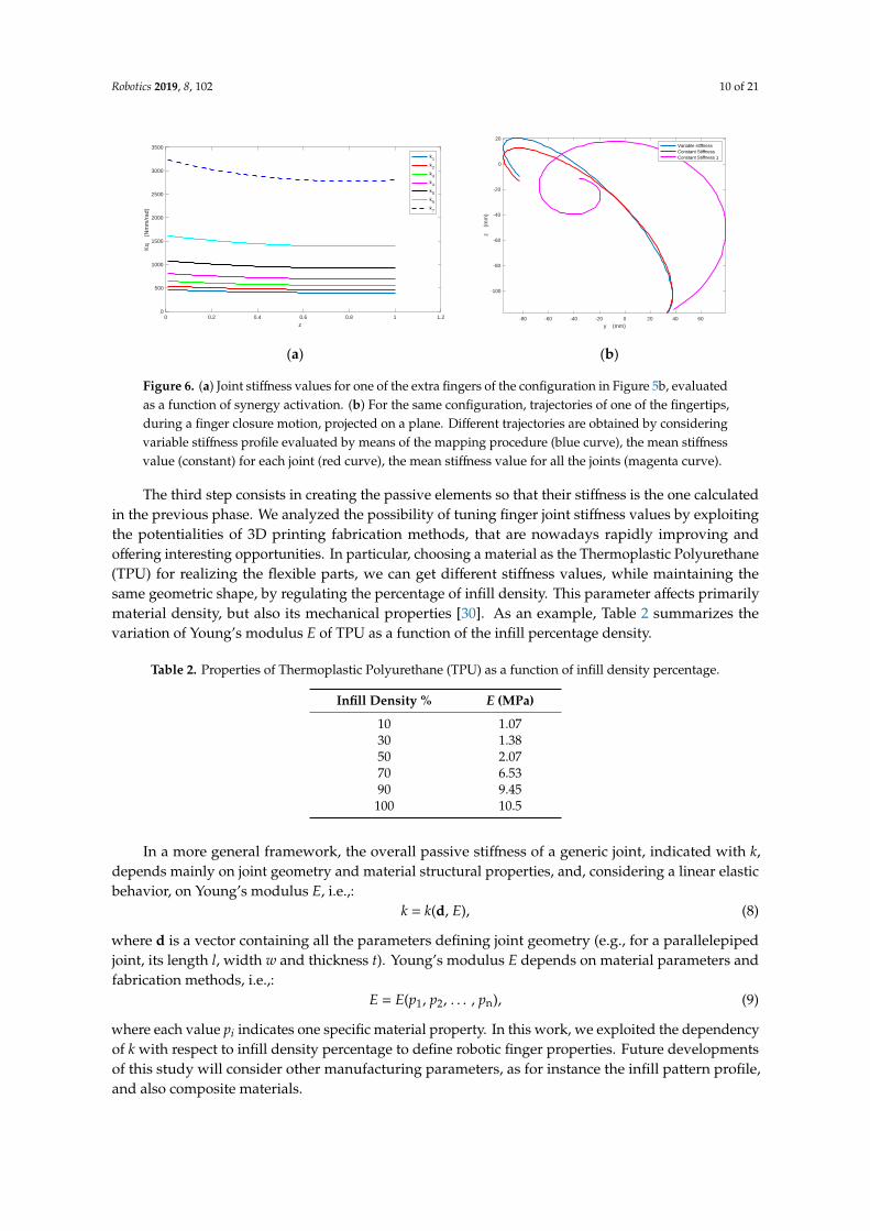
Given the previously introduced force distribution, we analyzed stress distribution on the mainelements of the finger transmission. The most stressed element results to be the sliding element. Thedimensions of the sliding element have been defined based on geometrical considerations summarizedin the preceding sections. On the motor side, the central pivot is tied to the tendon connected to thedriving pulley, that allows sliding. On the finger side, two tendons are connected to the finger pins.Figure 11a shows Von Mises equivalent stress distribution. It can be noticed that the central pivot is themost stressed part of the sliding element. There are peaks of stress concentration in the edges that arenot compatible with a standard ABS material. This drawback can be easily mitigated in the design and
Robotics 2019, 8, 102 15 of 21
prototyping phase by increasing fillet radii. Since this is the most stressed element of the transmissionsystem and it is not physically connected to other components, we can also consider different types ofmaterial to realize it, as for instance ABS reinforced with carbon or metal fiber [30], or metal alloys.
Robotics 2019, 8, 102 14 of 21
Figure 10. Sketch of the forces acting on the main elements of the finger actuation and transmission
system in quasistatic conditions. When the motor applies its maximum torque, 3.1 Nm at 12 V, the
force applied to the tendon driving the differential is F = 282 N. The forces applied to the tendons
driven by the differential and connected to the fingers is therefore F/2 = 141 N.
3.3.2. Stress Analysis Results
Given the previously introduced force distribution, we analyzed stress distribution on the main
elements of the finger transmission. The most stressed element results to be the sliding element. The
dimensions of the sliding element have been defined based on geometrical considerations
summarized in the preceding sections. On the motor side, the central pivot is tied to the tendon
connected to the driving pulley, that allows sliding. On the finger side, two tendons are connected to
the finger pins. Figure 11a shows Von Mises equivalent stress distribution. It can be noticed that the
central pivot is the most stressed part of the sliding element. There are peaks of stress concentration
in the edges that are not compatible with a standard ABS material. This drawback can be easily
mitigated in the design and prototyping phase by increasing fillet radii. Since this is the most stressed
element of the transmission system and it is not physically connected to other components, we can
also consider different types of material to realize it, as for instance ABS reinforced with carbon or
metal fiber [30], or metal alloys.
Rigid elements of finger phalanges have a quite robust shape; in Figure 11b we report as an
example the results of a FEM static simulation in which we applied a compressive loading of 40 N.
As it can be seen, the overall stress level is low.
(a) (b)
Figure 11. Main results of the static FEM analysis on some elements of the transmission and differential.Equivalent Von Mises stress distributions are reported. (a) Sliding element, (b) rigid element offinger phalanges.
Rigid elements of finger phalanges have a quite robust shape; in Figure 11b we report as anexample the results of a FEM static simulation in which we applied a compressive loading of 40 N.As it can be seen, the overall stress level is low.
4. Prototype Presentation
A simplified demonstrative prototype of the proposed double finger device is shown in Figure 1.As previously explained, the device has been designed to be wearable, robust and compliant to adapt todifferent object shapes. The device consists of two main parts, a support base and two flexible fingers.The flexible fingers have a modular structure, each module is composed of a 3D printed ABS polymericpart that acts as a rigid link and a TPU part that realizes the flexible joint. Soft rubber pads are glued tothe rigid links to increase the friction at possible contact areas. The modules are assembled by slidingthe flexible part in the rigid one (Figure 2). The support base of the finger is realized in ABS. It containsthe actuator, the differential and two elastic bands that allows the user to wear it on the forearm.
The actuator moves the fingers through a tendon connected to the sliding element that constitutethe differential. A hole in the rigid links allows the passage of a cable (Dyneema polyethylene fiber,Japan) which is used to realize the tendon driven actuation. The tendon wires run through the fingersand are attached on one side to the fingertips and on the other to the sliding element. Another tendonconnects the sliding element to a pulley connected to the actuator. The actuator used, as previouslyintroduced, is a Dynamixel servo AX12-A (Robotis, Korea) [42]. Principal details on the motor anddevice features are reported in Table 4. We use ArbotiX-M Robocontroller to drive the Dynamixelmotor [43]. This control solution for Dynamixel motors incorporates an AVR microcontroller, Xbeewireless radio and the motor driver.

Robotics 2019, 8, 102 16 of 21
Table 4. Main technical properties of the prototype.
Description Value Unit
Rigid module, dimension 20 × 31 × 12 mmFlexible module, dimension 20 × 18 × 2 mm
Support base, dimension (approx.) 170 × 50 × 40 mmActuator, dimension 71 × 71 × 45 mm
Actuator, weight 146 gMax torque (@ 12V) 3.1 Nm
Pulley radius 11 mmMax current (@ 12 V) 1.4 A
Operating angles 300 ◦
Max unloaded velocity 684 ◦/sTotal weight 210 g
Interfaces for controlling wearable extra fingers have been developed within this research activity,for the sake of brevity we report in this paper a brief summary on the main solutions. The key aspectsthat were considered in the design of these interfaces were reliability, easiness and intuitiveness ofuse also by untrained people, accessibility from people with partial upper limb impairments, andlimited costs. Different wearable interfaces have been developed to control wearable extra fingers,and also to let the user feel a haptic stimulus communicating a specific state of the robotic extra finger.An interesting example control device is the eCap, an Electromyography (EMG) interface embedded ina cap: wearing the eCap the user can control the flexion/extension of the robotic finger by contractingthe frontalis muscle by moving his or her eyebrows upwards. The motion of the robotic extra finger iscontrolled using a trigger signal based finite state machine (FSM), as detailed in [44].
Another possible interface is the so-called hRing, a ring that can be worn by the user on the healthyhand, provided by buttons for opening/closing the wearable extra fingers and with a vibrating motorproviding a haptic cutaneous feedback stimulus to the user’s healthy hand [44].
For control design, a simple and robust solution has been implemented. Device actuator is positioncontrolled, a linearly increasing/decreasing reference position value is sent to the actuator accordingto inputs provided by the users through the interface or state variations, as detailed in the following.The prototype proposed in this paper has not position/force sensors on the fingers, control systembehavior is developed on the basis of motor internal sensors only. In particular, it is possible to use theinternal controller available in the servomotor to control the exerted torque. This controller uses atorque estimation based on the measured load current. The torque control may be used to limit thegrasping force on the objects or to check whether an object is firmly grasped. This information can behaptically communicated to the user as a vibration signal if the hRing interface is employed. Exampleson the use of torque control can be found in [45].
Through the interfaces, the users control the motion/stop of the finger with a specific commandon the control interface (e.g., a single muscle contraction with the eCap, the activation of one of thetwo buttons on the hRing). Once the finger is stopped, another input (e.g., two contractions of themuscle, the activation of the second button in the hRing) switches the direction of motion from flexionto extension and vice versa. A software defined trigger stops the actuator’s motion once the objectis considered as grasped, to avoid a torque overloading situation. Object grasping is detected bycontinuous monitoring of the actuator’s shaft position and the exerted torque.
In particular, when flexion command is selected, a desired position for the servomotor ϑdes,corresponding to a configuration in which, both the extra fingers are completely flexed. For instance,for the device previously introduced, with 7 modules for both the fingers, from Equation (16), it resultsthat the overall displacement of the main tendon, needed to fully close the fingers, is ∆ltot = 28 mm.Considering that the pulley connected to the servomotor is rm = 11 mm, the corresponding rotationfor the motor is ϑdes =150◦. The desired value of the angular velocity (ωdes =33.3 ◦/s) is also set in the

Robotics 2019, 8, 102 17 of 21
position control system. When extension/release command is selected by the user, the desired positionis set to 0◦, which results in the finger completely extended, with the same desired velocity.
The lack of precision in sensing and control is compensated by the adaptability properties ofthe device, inherently provided by joint passive compliance and by the differential mechanism thatdecouples fingers’ closure motions [7]. More complex control strategies were tested in some preliminaryworks [18], but they were suitable for fully actuated devices and needed sophisticated and expensivesensors for human hand tracking, for example a Cyberglove [46]. Although these works providedus interesting results, we recognized that they were not suited for the application outside researchlaboratories, with patients dealing with everyday activities.
Figure 12 shows some examples of grasps realized with the wearable device. As it can be seen,even if the device is actuated by only one motor, the underactuated structure of the fingers and thedifferential system allow the device to adapt to different object shapes, realizing stable grasps of largeobjects, having a weight up to 2 kg, and also to grasp multiple objects. Device performance, in termsof payload (e.g., maximum weight of the grasped object, maximum fingertip force, maximum andminimum diameter of the grasped object), are summarized in Table 5. It is worth to notice that someof the grasps reported in Figure 12 would be weak or impossible with a single finger device (e.g.,Figure 12c–e) or with a double extra finger without differential mechanism as the one presented in [29](Figure 12c,e). Other grasp examples have been presented in the video S1 in Supplementary Materials.Robotics 2019, 8, 102 17 of 21
(a) (b) (c) (d) (e)
Figure 12. examples of grasps realized with the wearable device: (a) apple, (b) rectangular box,
(c) glass, (d) bottle, (e) two different objects (battery packs).
5. Discussion on Potential Applications, Links
Wearable robots present interesting design challenges, since they are expected to closely work
and collaborate with users, in an unstructured and dynamical environment. Wearable devices require
additional design requirements, concerning weight, adaptability to user’s body specificity, safety,
robustness, and easiness of use. A rather new research branch in wearable robotics deals with human
body augmentation. In this work, we analyzed a device for human hand augmentation, focusing on
its mechanical design, rather than on its control and interfacing with the human, that was the focus
of other works [44]. Human hand augmentation by means of robotic extra fingers represents an
interesting research topic, involving engineering as well as ethical and philosophical challenges.
With respect to other solutions available in the literature [16,17,20], the device that we propose
presents the following features:
Actuation: while other devices available in the literature have a rigid and fully
actuated structures, in the device presented in this work only one motor is necessary
to actuate both the single and the double finger configurations. This feature limits
the weight, complexity of the device, and improve its wearability and user comfort.
Modularity: as discussed in Section 2, the structure of the fingers is modular at the
phalanx level, the same modules can be used both for the single and double finger
configurations. The device can be easily adapted to user’s specific needs and features.
For instance, a smaller hand would need a device with smaller dimensions that can be
easily obtained realizing fingers with less modules.
Robustness, safety for the user: in this type of devices the fingers are the elements
more sensitive to unexpected contacts with the environment and shocks. Passive
elements present in the interphalangeal joints of the fingers are realized by TPU, a
material that presents high resistance to impacts and elongation at break. As a result,
the fingers are quite robust and can resist to uncertainties and unpredictable impacts
that may occur during activities of daily living (ADL). At the same time, their
compliance limits the risks for the user and for other people.
Adaptability: the compliant structure provided by deformable elements in
interphalangeal joints and the differential mechanism allow the device to
automatically adapt to different objects with different shapes and dimensions,
without the need of specific sensors on the fingers and complex control strategies.
Costs: the simple but versatile mechanical structure, the choice of widely diffused
and affordable manufacturing technologies and materials, and the modularity, lead
to a cost of the device that is quite limited.
We believe that the most impactful application of the device presented in this paper is
rehabilitation and assistance of patients with upper limb impairments, for example after a stroke [47].
Figure 12. Examples of grasps realized with the wearable device: (a) apple, (b) rectangular box, (c) glass,(d) bottle, (e) two different objects (battery packs).
Table 5. Main performance parameters of the prototype.
Description Value Unit
Max payload 2 kgMax force at the fingertip (closed) 12 NMax force at the fingertip (open) 6 N
Diameter of the smallest graspable object 17 mmDiameter of the largest graspable object 180 mm
5. Discussion on Potential Applications, Links
Wearable robots present interesting design challenges, since they are expected to closely workand collaborate with users, in an unstructured and dynamical environment. Wearable devices requireadditional design requirements, concerning weight, adaptability to user’s body specificity, safety,robustness, and easiness of use. A rather new research branch in wearable robotics deals with humanbody augmentation. In this work, we analyzed a device for human hand augmentation, focusingon its mechanical design, rather than on its control and interfacing with the human, that was the

Robotics 2019, 8, 102 18 of 21
focus of other works [44]. Human hand augmentation by means of robotic extra fingers represents aninteresting research topic, involving engineering as well as ethical and philosophical challenges.
With respect to other solutions available in the literature [16,17,20], the device that we proposepresents the following features:
• Actuation: while other devices available in the literature have a rigid and fully actuated structures,in the device presented in this work only one motor is necessary to actuate both the single andthe double finger configurations. This feature limits the weight, complexity of the device, andimprove its wearability and user comfort.
• Modularity: as discussed in Section 2, the structure of the fingers is modular at the phalanx level,the same modules can be used both for the single and double finger configurations. The device canbe easily adapted to user’s specific needs and features. For instance, a smaller hand would need adevice with smaller dimensions that can be easily obtained realizing fingers with less modules.
• Robustness, safety for the user: in this type of devices the fingers are the elements more sensitiveto unexpected contacts with the environment and shocks. Passive elements present in theinterphalangeal joints of the fingers are realized by TPU, a material that presents high resistanceto impacts and elongation at break. As a result, the fingers are quite robust and can resist touncertainties and unpredictable impacts that may occur during activities of daily living (ADL).At the same time, their compliance limits the risks for the user and for other people.
• Adaptability: the compliant structure provided by deformable elements in interphalangeal jointsand the differential mechanism allow the device to automatically adapt to different objects withdifferent shapes and dimensions, without the need of specific sensors on the fingers and complexcontrol strategies.
• Costs: the simple but versatile mechanical structure, the choice of widely diffused and affordablemanufacturing technologies and materials, and the modularity, lead to a cost of the device that isquite limited.
We believe that the most impactful application of the device presented in this paper is rehabilitationand assistance of patients with upper limb impairments, for example after a stroke [47]. Stroke is abrain attack, affecting 17 million people worldwide each year, it is the second most common cause ofdeath and a leading cause of adult physical disability (http://strokeeurope.eu/). Impairment of thehand, and in particular of its grasping and dexterous manipulation capabilities is one of the commondeficits after a stroke. Approximately 60% of stroke survivors suffer from some form of sensorimotorimpairment associated with their hand. Rehabilitation processes could take advantage from roboticdevices, that can be used to practice intense movement training at home. Supernumerary fingers enablepatients to execute grasp and release exercises and practice intensively using repetitive movements.
Different configurations for the robotic extra fingers, with one or two fingers, have been realizedfollowing the principles that we summarized in the previous sections and are now available fortesting. Double configurations allow more stable grasps and the possibility of carrying heavier loads.In addition to rehabilitation purposes, supernumerary robotic fingers can increase patients’ graspingcapabilities, especially in objects manipulation, thereby improving their independence in ADL, andsimultaneously decreasing the need of compensatory unnatural motor strategies for solving everydaytasks. Supernumerary limbs will provide novel opportunities to recover missing abilities, resulting inimprovements of patients’ quality of life.
The devices were tested with chronic stroke patients through qualitative experiments based onADL and preliminary results are widely discussed in [19,45]. The goal of the tests was to evaluatehow quickly and easily the patients could learn to use the device in ADL. Different applications wereconsidered (e.g., kitchen scenario, consisting in preparing breakfast and lunch, some tools activities,using the extra finger as an active hook, etc.). The initial tests gave encouraging results; users couldcomplete the tasks reducing the time and with good success rates.

Robotics 2019, 8, 102 19 of 21
6. Conclusions
In this paper, we summarized the work regarding the mechanical design of supernumerary roboticfingers that can be used for augmenting and compensating the human hand manipulation abilities.Wearability requirements set constraints on the hardware structure, that needs to be light, robust andsafe. We focused in particular on the analysis of the transmission system that is needed when more thanone finger is employed and all the fingers are actuated with the same motor. We are still optimizing thedesign, by further studying the possibility of exploiting additive manufacturing technology to changethe stiffness of the finger’s joints. We are working on integrating the extra fingers with other devices,as for instance assistive tools for wrist motion and arm support, investigating the possibility of usingour devices in patients affected by other neurological diseases affecting hand grasping.
Supplementary Materials: The following are available online at http://www.mdpi.com/2218-6581/8/4/102/s1,Video S1: Design of multiple wearable extra fingers for human hand augmentation.
Author Contributions: Conceptualization, G.S.; Investigation, M.M., Z.I. and M.C.V.; Methodology, M.M., M.C.V.,M.P., D.P. and G.S.; Supervision, M.P. and D.P.
Funding: This research was funded by the European Union EU H2020 projects under grant n. 780073 of theproject “INBOTS Inclusive Robotics for a Better Society.
Conflicts of Interest: The authors declare no conflict of interest.
References
1. Mason, M.T.; Salisbury, J.K. Robots Hands and the Mechanics of Manipulation; MIT Press: Cambridge, MA, USA,1985; ISBN 9780262132053.
2. Carbone, G. Grasping in Robotics; Springer: Dordertch, The Netherlands, 2013. [CrossRef]3. Fukaya, N.; Toyama, S.; Asfour, T.; Dillmann, R. Design of the TUAT/Karlsruhe humanoid hand. In
Proceedings of the IEEE/RSJ International Conference on Intelligent Robots and Systems, Takamatsu, Japan,31 October–5 November 2000; pp. 1754–1759. [CrossRef]
4. Butterfass, J.; Grebenstein, M.; Liu, H.; Hirzinger, G. DLR-hand II: Next generation of a dexterous robot hand.In Proceedings of the IEEE International Conference on Robotics and Automation, Seoul, Korea, 21–26 May2001; pp. 109–114. [CrossRef]
5. Martin, E.; Desbiens, A.L.; Laliberté, O.T.; Gosselin, C. SARAH hand used for space operation on STVF robot.In Proceedings of the Intelligent Manipulation and Grasping, Genoa, Italy, 1–2 July 2004; pp. 279–284.
6. Roccella, S.; Carrozza, M.C.; Cappiello, G.; Dario, P.; Cabibihan, J.J.; Zecca, M.; Hiwa, H.; Itoh, K.;Matsumoto, M.; Takanishi, A. Design, fabrication and preliminary results of a novel anthropomorphic handfor humanoid robotics: RCH-1. In Proceedings of the IEEE/RSJInternational Conference on Intelligent Robotsand Systems, Sendai, Japan, 28 September–2 October 2004; pp. 266–271, ISBN 0780384636.
7. Dechev, N.; Cleghorn, W.L.; Nauman, S. Multiple finger, passive adaptive grasp prosthetic hand. Mech.Mach. Theory 1999, 36, 1157–1173. [CrossRef]
8. Raparelli, T.; Mattiazzo, G.; Mauro, S.; Velardocchia, M. Design and development of a Pneumaticanthropomorphic hand. J. Robot. Syst. 2000, 17, 1–15. [CrossRef]
9. Maffiodo, D.; Raparelli, T. Three-Fingered Gripper with Flexure Hinges Actuated by Shape Memory AlloyWires. Int. J. Autom. Technol. 2017, 11, 355–360. [CrossRef]
10. Niola, V.; Penta, F.; Rossi, C.; Savino, S. An underactuated mechanical hand: Theoretical studies andprototyping. Int. J. Mech. Control 2015, 16, 11–19.
11. Cosenza, C.; Niola, V.; Savino, S. Analytical study for the capability implementation of an underactuatedthree-finger hand. Mech. Mach. Sci. 2019, 65, 161–168. [CrossRef]
12. Niola, V.; Rossi, C.; Savino, S.; Timpone, F. Study of an underactuated mechanical finger driven by tendons.Int. J. Autom. Technol. 2017, 11, 344–354. [CrossRef]
13. Maffiodo, D.; Raparelli, T. Comparison among different modular SMA actuated flexible fingers. Mech. Mach.Sci. 2019, 68, 324–331. [CrossRef]
14. Carbone, G.; Rossi, C.; Savino, S. Performance comparison between FEDERICA hand and LARM hand. Int.J. Adv. Robot. Syst. 2015, 12, 90. [CrossRef]

Robotics 2019, 8, 102 20 of 21
15. Kobayashi, H.; Hyodo, K.; Ogane, D. On tendon-driven robotic mechanisms with redundant tendons. Int. J.Robot. Res. 1998, 17, 561–571. [CrossRef]
16. Parietti, F.; Asada, H. Supernumerary robotic limbs for human body support. IEEE Trans. Robot. 2016, 32,301–311. [CrossRef]
17. Wu, F.Y.; Asada, H.H. “Hold-and-manipulate” with a single hand being assisted by wearable extra fingers.In Proceedings of the 2015 IEEE International Conference on Robotics and Automation (ICRA), Seattle, WA,USA, 26–30 May 2015.
18. Prattichizzo, D.; Malvezzi, M.; Hussain, I.; Salvietti, G. The sixth-finger: A modular extra-finger to enhancehuman hand capabilities. In Proceedings of the 23rd IEEE International Symposium on Robot and HumanInteractive Communication, Edinburgh, UK, 25–29 August 2014; pp. 993–998. [CrossRef]
19. Hussain, I.; Salvietti, G.; Spagnoletti, G.; Prattichizzo, D. The soft-sixthfinger: A wearable emg controlledrobotic extra-finger for grasp compensation in chronic stroke patients. IEEE Robot. Autom. Lett. 2016, 1,1000–1006. [CrossRef]
20. Hu, Y.; Leigh, S.W.; Maes, P. Hand Development Kit: Soft Robotic Fingers as Prosthetic Augmentation of theHand. In Proceedings of the Adjunct Publication of the 30th Annual ACM Symposium on User InterfaceSoftware and Technology, Québec City, QC, Canada, 22–25 October 2017.
21. Hussain, I.; Salvietti, G.; Spagnoletti, G.; Malvezzi, M.; Cioncoloni, D.; Rossi, S.; Prattichizzo, D. A softsupernumerary robotic finger and mobile arm support for grasping compensation and hemiparetic upperlimb rehabilitation. Robot. Auton. Syst. 2017, 93, 1–12. [CrossRef]
22. Laliberté, T.; Gosselin, C.M. Underactuation in space robotic hands. In Proceedings of the InternationalSymposium on Artificial Intelligence, Robotics and Automation in Space, Montréal, QC, Canada,18–22 June 2001.
23. Birglen, L.; Gosselin, C.M. Force Analysis of Connected Differential Mechanisms: Application to Grasping.Int. J. Robot. Res. 2006, 25, 1033–1046. [CrossRef]
24. Zappatore, G.A.; Reina, G.; Messina, A. Analysis of a highly underactuated robotic hand. Int. J. Mech. Control2017, 18, 17–24.
25. Birglen, L.; Gosselin, C.M. On the force capability of underactuated fingers. In Proceedings of the IEEEInternational Conference on Robotics and Automation, Taipei, Taiwan, 14–19 September 2003; pp. 1139–1145.[CrossRef]
26. Massa, B.; Roccella, S.; Carrozza, M.C.; Dario, P. Design and development of an underactuated prosthetichand. In Proceedings of the 2002 IEEE International Conference on Robotics and Automation, Washington,DC, USA, 11–15 May 2002; pp. 3374–3379. [CrossRef]
27. Baril, M.; Laliberté, T.; Gosselin, C.; Routhier, F. On the design of a mechanically programmable underactuatedanthropomorphic prosthetic gripper. J. Mech. Des. 2013, 135, 121008. [CrossRef]
28. Kontoudis, G.P.; Liarokapis, M.V.; Zisimatos, A.G.; Mavrogiannis, C.I.; Kyriakopoulos, K.J. Open-source,anthropomorphic, underactuated robot hands with a selectively lockable differential mechanism: Towardsaffordable prostheses. In Proceedings of the 2015 IEEE/RSJ International Conference on Intelligent Robotsand Systems (IROS), Hamburg, Germany, 28 September–2 October 2015; pp. 5857–5862.
29. Hussain, I.; Spagnoletti, G.; Salvietti, G.; Prattichizzo, D. Toward wearable supernumerary robotic fingers tocompensate missing grasping abilities in hemiparetic upper limb. Int. J. Robot. Res. 2017, 36, 1414–1436.[CrossRef]
30. Ning, F.; Cong, W.; Qiu, J.; Wei, J.; Wang, S. Additive manufacturing of carbon fiber reinforced thermoplasticcomposites using fused deposition modeling. Compos. Part B Eng. 2015, 80, 369–378. [CrossRef]
31. Valigi, M.C.; Logozzo, S.; Canella, G. A new automated 2 DOFs 3D desktop optical scanner. In Mechanismsand Machine Science; Springer: Berlin, Germany, 2017; Volume 47, pp. 231–238. [CrossRef]
32. Valigi, M.C.; Logozzo, S.; Canella, G. A robotic 3D vision system for automatic cranial prostheses inspection.Mech. Mach. Sci. 2018, 49, 328–335. [CrossRef]
33. Salvietti, G.; Hussain, I.; Malvezzi, M.; Prattichizzo, D. Design of the passive joints of underactuated modularsoft hands for fingertip trajectory tracking. IEEE Robot. Autom. Lett. 2017, 2, 2008–2015. [CrossRef]
34. Wu, F.Y.; Asada, H. Bio-Artificial Synergies for Grasp Posture Control of Supernumerary Robotic Fingers; MITPress: Cambridge, MA, USA, 2014.
35. Santello, M.; Flanders, M.; Soechting, J.F. Postural Hand Synergies for Tool Use. J. Neurosci. 1998, 18,10105–10115. [CrossRef]

Robotics 2019, 8, 102 21 of 21
36. Malvezzi, M.; Valigi, M.C.; Salvietti, G.; Iqbal, Z.; Hussain, I.; Prattichizzo, D. Design criteria for wearablerobotic extra–fingers with underactuated modular structure. Mech. Mach. Sci. 2019, 68, 509–517. [CrossRef]
37. Malvezzi, M.; Gioioso, G.; Salvietti, G.; Prattichizzo, D. SynGrasp: A Matlab Toolbox for Underactuated andCompliant Hands. IEEE Robot. Autom. Mag. 2015, 22, 52–68. [CrossRef]
38. Cobos, S.; Ferre, M.; Uran, M.S.; Ortego, J.; Pena, C. Efficient human hand kinematics for manipulationtasks. In Proceedings of the 2008 IEEE/RSJ International Conference on Intelligent Robots and Systems, Nice,France, 22–26 September 2008; pp. 2246–2251.
39. Bianchi, M.; Liarokapis, M.V. HandCorpus, a new open-access repository for sharing experimental dataand results on human and artificial hands. In Proceedings of the IEEE World Haptics Conference (WHC),Daejeon, Korea, 14–17 April 2013.
40. Dollar, A.M.; Howe, R.D. The highly adaptive sdm hand: Design and performance evaluation. Int. J. Robot.Res. 2010, 29, 585–597. [CrossRef]
41. Ahmed, M.; Islam, M.; Vanhoose, J.; Rahman, M. Comparisons of Elasticity Moduli of Different SpecimensMade Through Three Dimensional Printing. 3D Print. Addit. Manuf. 2017, 4, 105–109. [CrossRef]
42. Robotis. Dynamixel Mx-28t Robot Actuator. 2012. Available online: http://www.trossenrobotics.com/
dynamixel-mx-28-robotactuator.aspx (accessed on 10 December 2019).43. ArbotiX. Arbotix-m Robocontroller, Open Source. 2012. Available online: http://www.trossenrobotics.com/p/
arbotix-robotcontroller.aspx (accessed on 10 December 2019).44. Spagnoletti, G.; Hussain, I.; Pacchierotti, C.; Salvietti, G.; Prattichizzo, D. The hRing: A haptic interface for an
extra robotic finger. In Proceedings of the IEEE Haptic symposium, Philadelphia, PA, USA, 8–11 April 2016.45. Salvietti, G.; Hussain, I.; Cioncoloni, D.; Taddei, S.; Rossi, S.; Prattichizzo, D. Compensating Hand Function in
Chronic Stroke Patients Through the Robotic Sixth Finger. Trans. Neural Syst. Rehabil. Eng. 2016. [CrossRef]46. Cyberglove. Cyberglove Systems. 2019. Available online: http://www.cyberglovesystems.com/ (accessed on
10 December 2019).47. Mozaffarian, D.; Benjamin, E.J.; Go, A.S.; Arnett, D.K.; Blaha, M.J.; Cushman, M.; Howard, V.J. Heart
disease and stroke statistics—2016 update: A report from the American Heart Association. Circulation 2015.[CrossRef]
© 2019 by the authors. Licensee MDPI, Basel, Switzerland. This article is an open accessarticle distributed under the terms and conditions of the Creative Commons Attribution(CC BY) license (http://creativecommons.org/licenses/by/4.0/).