0WB080003(slide)SGSN9810 V800 (UAG)Hardware System-20090228-B-V2.0
54
www.huawei.com Copyright © 2006 Huawei Technologies Co., Ltd. All rights reserved. UAG Hardware System
-
Upload
akhtar-zaman -
Category
Documents
-
view
127 -
download
8
Transcript of 0WB080003(slide)SGSN9810 V800 (UAG)Hardware System-20090228-B-V2.0

www.huawei.com
Copyright © 2006 Huawei Technologies Co., Ltd. All rights reserved.
UAG Hardware System

Copyright © 2006 Huawei Technologies Co., Ltd. All rights reserved. Page2
References
SGSN V8R8 UAG product manual

Copyright © 2006 Huawei Technologies Co., Ltd. All rights reserved. Page3
Objectives
Upon completion of this course, you will be able to:
Describe UAG product networking
Outline UAG logical structure
Outline UAG hardware structure
Outline UAG board function
Describe UAG signalling and data flow

Copyright © 2006 Huawei Technologies Co., Ltd. All rights reserved. Page4
Contents
1. UAG Overview
2. UAG Hardware Structure
3. UAG Signalling and Data Flows

Copyright © 2006 Huawei Technologies Co., Ltd. All rights reserved. Page5
Contents
1. UAG Overview
2. UAG Hardware Structure
3. UAG Signalling and Data Flows

Copyright © 2006 Huawei Technologies Co., Ltd. All rights reserved. Page6
The Location of UAG
Internet
PSTN
UAGUAG
Copyright © 2006 Huawei Technologies Co., Ltd. All rights reserved. Page7
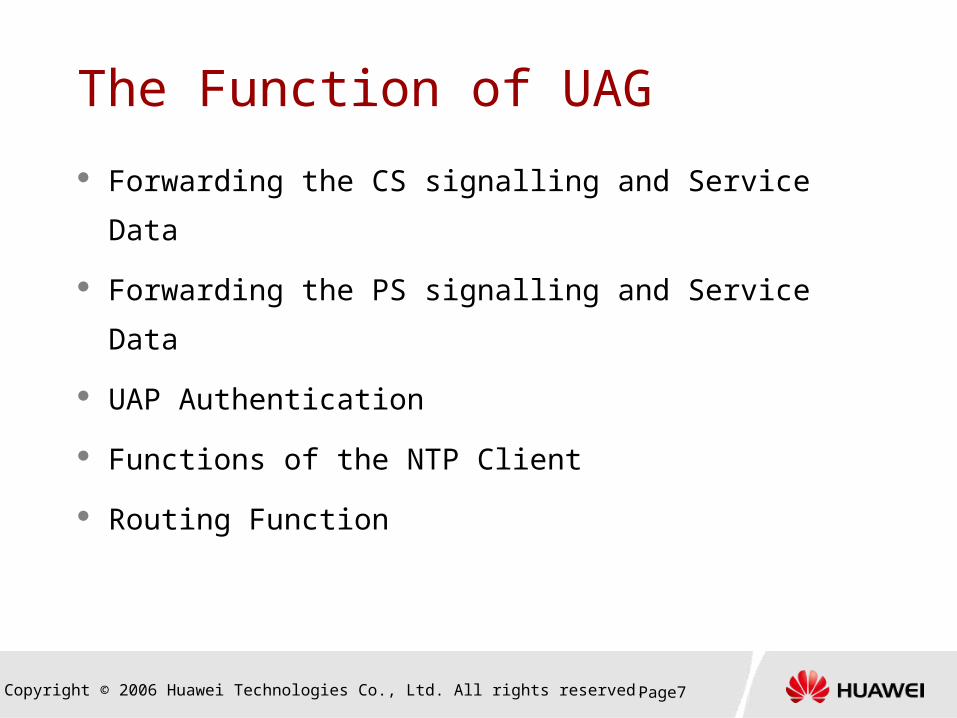
The Function of UAG
Forwarding the CS signalling and Service Data
Forwarding the PS signalling and Service Data
UAP Authentication
Functions of the NTP Client
Routing Function

Copyright © 2006 Huawei Technologies Co., Ltd. All rights reserved. Page8
Contents
1. UAG Overview
2. UAG Hardware Structure
3. UAG Signalling and Data Flows

Copyright © 2006 Huawei Technologies Co., Ltd. All rights reserved. Page9
2. UAG Hardware Structure
2.1 UAG Logical Structure
2.2 UAG Hardware Structure
2.3 UAG Switching Subsystem
2.4 UAG OAM Subsystem
2.5 UAG Clock Subsystem
2.6 UAG Interface Subsystem
Contents

Copyright © 2006 Huawei Technologies Co., Ltd. All rights reserved. Page10
UAG Logical Structure
DataData forwarding forwarding subsystemsubsystem
Signalling Signalling processing processing subsystemsubsystem
NTPNTPsubsystemsubsystem
OAM OAM subsystemsubsystem
Clock Clock subsystemsubsystem
ATM ATM switching switching subsystemsubsystem
AP/MGW/AP/MGW/MSC ServerMSC ServerSGSN/NTPSGSN/NTP/AHR/AHR
M2000/M2000/LMTLMT
BITSBITS

Copyright © 2006 Huawei Technologies Co., Ltd. All rights reserved. Page11
UAG Subsystem Function O&M Subsystem
The O&M subsystem offers the external O&M maintenance interface and implements the functions of system maintenance, configuration, performance, alarm, and log.
The hardware function is implemented by the UOMU and UFSU boards.
Clock Subsystem The clock subsystem obtains clock signals from the BITS and
the STM-1/STM-4 optical interfaces, and offers the stratum-2 clock to the STM-1/STM-4 optical interface of the UAG.
The hardware function is implemented by the UCKI board.

Copyright © 2006 Huawei Technologies Co., Ltd. All rights reserved. Page12
UAG Subsystem Function ATM Switching Subsystem
The ATM switching subsystem implements the ATM exchange and interconnection among subracks.
The hardware function is implemented by the URCU, UPIU, and UFCU boards.
NTP Subsystem The NTP subsystem implements the function of the NTP client
and obtains timing information on the IP network from the NTP server.
The hardware function is implemented by the UGTP board.

Copyright © 2006 Huawei Technologies Co., Ltd. All rights reserved. Page13
UAG Subsystem Function Signalling Processing Subsystem
The signalling processing subsystem processes the eIu and Iu interface signalling, and authorizes and manages the UAP.
The hardware function is implemented by the UASU board.
Data Forwarding Subsystem The data forwarding subsystem offers the eIu interface, the
Iu interface, the Hg interface, and the interface from the UAG to the NTP server. It forwards user data between the eIu interface and the Iu interface.
The hardware function is implemented by the UAFU and UPIU boards

Copyright © 2006 Huawei Technologies Co., Ltd. All rights reserved. Page14
2. UAG Hardware Structure
2.1 UAG Logical Structure
2.2 UAG Hardware Structure
2.3 UAG Switching Subsystem
2.4 UAG OAM Subsystem
2.5 UAG Clock Subsystem
2.6 UAG Interface Subsystem
Contents

Copyright © 2006 Huawei Technologies Co., Ltd. All rights reserved. Page15
UAG Cabinet
UAG system uses the
Huawei N68-22 cabinet,
which complies with the
IEC297 and IEEE
standards.
Air deflector
Air deflector
Air deflector
Dummy panel
Power distribution box
PSM subrack
UAFU
UAFU
UASU
UASU
UASU
UASU
URCU
URCU
UASU
UASU
UASU
UASU
UASU
UASU
UALU
UPWR
UPWR
PSM subrack
UAFU
UAFU
UFCU
UFCU
URCU
URCU
UOMU
UOMU
UGTP
UGTP
UALU
UPWR
UPWR
PSM subrack
UPWR
UPWR
PSM subrack
UPWR
UPWR
UAFU
UAFU
UASU
UASU
UASU
UASU
URCU
URCU
UASU
UASU
UASU
UASU
UASU
UASU
UALU
UAFU
UAFU
UASU
UASU
UASU
UASU
URCU
URCU
UASU
UASU
UASU
UASU
UASU
UASU
UALU
UAFU
UAFU

Copyright © 2006 Huawei Technologies Co., Ltd. All rights reserved. Page16
UAG Subrack: Switching Subrack
The switching subrack is configured with the UOMU and UFCU boards. Only one switching subrack is required.
The fundamental functions of the switching subrack are listed as follows:
Forwarding data among the PSM subracks Offering the O&M interfaces
UASU0
UPIU
UPIU
UPIU
UASU
UFCU
UFCU
UAFU
UAFU
UPIU
UACU
UBIU
UACU
UBIU
UFSU
UCKI
UFSU
URCU
UOMU
URCU
UOMU
UGTP
UGTP
UALU
UPWR
UPWR
UPWR
UPWR
1 2 3 4 5 6 7 8 9 10 11 12 13 14 15 16 17,18 19,20
UCKI
ULAN
ULAN

Copyright © 2006 Huawei Technologies Co., Ltd. All rights reserved. Page17
UAG Subrack: Extension Subrack
The SGSN9810 can configure 0 to 3 extension subracks.
Extension subracks process only services.
UAFU0
UAFU
UASU
UASU
UASU
UASU
UACU
UBIU
UACU
UBIU
UPIU
UPIU
URCU
UAFU
URCU
UAFU
UASU
UASU
UASU
UASU
UALU
UPWR
UPWR
UPWR
UPWR
1 2 3 4 5 6 7 8 9 10 11 12 13 14 15 16 17,18 19,20
UPIU
UPIU

Copyright © 2006 Huawei Technologies Co., Ltd. All rights reserved. Page18
2. UAG Hardware Structure
2.1 UAG Logical Structure
2.2 UAG Hardware Structure
2.3 UAG Switching Subsystem
2.4 UAG OAM Subsystem
2.5 UAG Clock Subsystem
2.6 UAG Interface Subsystem
Contents

Copyright © 2006 Huawei Technologies Co., Ltd. All rights reserved. Page19
UAG Switching Subsystem
UBIU
URCU
UPIU
UFCU
UBIU
URCU
UBIU
URCU
FiberFiber
Switching subrackSwitching subrackExtensionExtension subracksubrack
ExtensionExtension subracksubrack

Copyright © 2006 Huawei Technologies Co., Ltd. All rights reserved. Page20
Communication Within Subracks
UPIU
UAFU
UASU
UGTP
BUSBUS
The different boards of the same subrack will use the
bus of the back board to communicate with each other.

Copyright © 2006 Huawei Technologies Co., Ltd. All rights reserved. Page21
Communication Between Subracks Different boards of different subrack will
communicate to each other via URCU/UFCU.
UBIU
URCU
UPIU
UFCU
UBIU
URCU
UGTP
UASU
BUSBUSBUSBUS
Switching Switching Extension Extension Fiber Fiber Fiber Fiber

Copyright © 2006 Huawei Technologies Co., Ltd. All rights reserved. Page22
UFCU
UFCU:
The Frame Connect Unit (UFCU) is the
switching center of UAG.
The UFCU can be inserted in slots 0–5
and 10–15 in the PSM switching
subrack in the front position.RST
CO
M1
0/10
0BT
ALMRUN
ACT
Interface Description Function
COM RJ45 serial port (RS232) Provides the test function of the UFCU to external devices.
10/100BT
10/100 Mbit/s test network port
Provides the test function of the UFCU to external devices.

Copyright © 2006 Huawei Technologies Co., Ltd. All rights reserved. Page23
UFCUIndicator Color Description Meaning Normal
State
RUN Green Board running indicator
FPGA loading: flashing in the frequency of 1 HzNormal running: flashing in the frequency of 0.5 Hz
Flashing in the frequency of 0.5 Hz
ALM Yellow Board fault indicator
OFF: board working normallyON: board failure
OFF
ACT Green 1+1 active/standby state indicator
OFF: standby boardON: active board
-
Blue indicator
Blue Hot-swap indicator (at the bottom of the panel)
OFF: board working normallyON: Before clipping the ejector lever after inserting the board into the subrackAfter loosing the ejector lever when the board is switched onCompliable to the hot swapping specifications. You can pull out the UFCU when this indicator is on.
OFF

Copyright © 2006 Huawei Technologies Co., Ltd. All rights reserved. Page24
UFCU Operation Environment The UFCU communicates
with the UPIU, its back board, through the high speed serial port and the configuration network port.
The UFCU communicates with the other boards in the subrack through the data bus.
The UFCU communicates with the URCU in the PSM service subrack through the fiber led out through the UPIU.
UAIC UAIC
UPIU
UFCU
URCU
Optical port Optical port
Data bus
High-speedserial port
Conf.netowrk port

Copyright © 2006 Huawei Technologies Co., Ltd. All rights reserved. Page25
UPIU
UPIU:
The back board of UFCU/UAFU.
Providing Ethernet or Giga bit/s or ATM
interface by using different PMC board:
UEEC: 10M/100M Ethernet port;
UEFC: 1000M Ethernet( Giga bps) port;
UAIC: ATM optical port.
UPIU only use UAIC PMC board when
work with UFCU.
LNK
RXTX
M/S-LINK
ACT
ALMRUN
P0
P1
P2
P3
P0
P1
P2
P3
UEEC
UEFC/
UAIC

Copyright © 2006 Huawei Technologies Co., Ltd. All rights reserved. Page26
2. UAG Hardware Structure
2.1 UAG Logical Structure
2.2 UAG Hardware Structure
2.3 UAG Switching Subsystem
2.4 UAG OAM Subsystem
2.5 UAG Clock Subsystem
2.6 UAG Interface Subsystem
Contents

Copyright © 2006 Huawei Technologies Co., Ltd. All rights reserved. Page27
UAG OAM Subsystem
LMT
UOMU/UFSUUOMU/UFSU
UFCU/UPIUUFCU/UPIU
URCU/UBIUURCU/UBIU URCU/UBIUURCU/UBIU
UASU..UASU.. UGTP..UGTP..UASU..UASU.. UAFU..UAFU..
Extension Extension Switching Switching
ULANULAN
Upper Eth portLower Eth port
Alarm boxAlarm box
EthEthFiber Fiber Bus Bus
Serial cableSerial cable
COM port

Copyright © 2006 Huawei Technologies Co., Ltd. All rights reserved. Page28
UAG OAM Subsystem
Normal maintenance route:
LMT—UOMU—UFCU—URCU—UGTP/UASU etc.
Software loading route:
(1) LMT—UOMU—ULAN—URCU( switching subrack )—
UFCU ; then;
(2) UOMU—UFCU—URCU—UGTP/UASU etc.

Copyright © 2006 Huawei Technologies Co., Ltd. All rights reserved. Page29
UOMU
UOMU is the OAM center of UAG:
Configuration management, performance
management, security management and
log management
Query control
User or signal tracing
CO
M
ALMRUN
RST
ACT

Copyright © 2006 Huawei Technologies Co., Ltd. All rights reserved. Page30
UFSU
UFSU: Flash Disk Storage Unit, the
backboard of UOMU.
Supports level conversion of the 2-port
asynchronous serial port signals from the UOMU
and provides physical interfaces to two
asynchronous serial ports.
Holds the hard disk of the UOMU and stores
system details such as system configuration data.
Provides external optical port and network port
for the UOMU.
RUN ALM
PWR
CO
M1
CO
M2
10
/100
M0
10
/100
M1
HD
RX
TX
ATM 155M

Copyright © 2006 Huawei Technologies Co., Ltd. All rights reserved. Page31
URCU
URCU: Subrack Control Unit, is the
OAM center of a subrack.
Each PSM subrack is configured with two
URCU boards that are inserted in slot 6 and
slot 8. The URCU boards are configured in
1+1 backup mode.
URCU provide the data transport channel of
different boards in the same subrack or in
different subrack.
CO
M1
0/1
00
BT
ALM RUN
RST
DOMADOMB

Copyright © 2006 Huawei Technologies Co., Ltd. All rights reserved. Page32
UBIU UBIU: Back Interface Unit, is the backboard of URCU.
The UBIU provides external ports for the URCU:
Serial ports
Ethernet port
155Mbit/s optical port
UBIU also handle the clock signal:
Receives the 8K clock signal from the sub-board UFIU of the URCU. ( For extension subrack UBIU)
Receives the 8K clock signal from UCKI. ( For switching subrack UBIU)
8K
_IN
LNK ALM
PWR
8K
_O
UT
10
/10
0M
RXTX
ATM155
CO
M1
CO
M2
CO
M2
+
2M
_O
UT
12
M_
OU
T2

Copyright © 2006 Huawei Technologies Co., Ltd. All rights reserved. Page33
UACU
DOMB DOMA
UACU: Auxiliary Control Unit, cooperate with URCU to perform the management of a subrack.
Each PSM subrack is configured with two
UACU boards inserted in slot 7 and slot 9 in
the rear position.
The URCU in slot 6 is used in co-ordination
with the UACU in slot 9 and the URCU in slot 8
is used in co-ordination with UACU in slot 7.

Copyright © 2006 Huawei Technologies Co., Ltd. All rights reserved. Page34
URCU/UBIU/UACU Cooperation
Bus A Bus B
U
R
C
U
UBIU UBIU
UACU UACU
Optical port
SPB SPB
SPB: Serv ice Processing Board
Optical port
U
F
I
U
U
R
C
U
U
F
I
U
Optical portelectric signal
Async.serial port

Copyright © 2006 Huawei Technologies Co., Ltd. All rights reserved. Page35
2. UAG Hardware Structure
2.1 UAG Logical Structure
2.2 UAG Hardware Structure
2.3 UAG Switching Subsystem
2.4 UAG OAM Subsystem
2.5 UAG Clock Subsystem
2.6 UAG Interface Subsystem
Contents

Copyright © 2006 Huawei Technologies Co., Ltd. All rights reserved. Page36
UAG Clock Subsystem
UCKI
UBIU
UPIU UPIU UPIU
PSM servicesubrack
PSM servicesubrack
PSM servicesubrack
. . .
. . .
External clock input
PSM switchingsubrack
Internal clock bus
STM-1 STM-1 STM-1

Copyright © 2006 Huawei Technologies Co., Ltd. All rights reserved. Page37
UAG Clock Subsystem
In the PSM switching subrack, the UBIU receives
clock signals from the UCKI and synchronizes these
signals to the UPIU in this subrack through the
internal clock bus.
The UPIU multiplexes the clock signals to the STM-1
fiber and sends the system synchronization clock to
each PSM service subrack. This guarantees the clock
synchronization of the whole system.

Copyright © 2006 Huawei Technologies Co., Ltd. All rights reserved. Page38
UCKI
UCKI: Clock Unit, It is inserted in slots 13
and 15 in the PSM basic subrack. Each
UCKI occupies two back board slots. BITS1
1
RUN ALM
ACT
BITS2LINE1LINE2
357
2468
91113
15
101214
16
RST
Interface Description Function
BITS1 2 MHz or 2 Mbit/s clock input port Extract 2 MHz or 2 Mbit/s clock signals as the reference source.
BITS2 2 MHz or 2 Mbit/s clock input port Extract 2 MHz or 2 Mbit/s clock signals as the reference source.
LINE1 E1 2 MHz clock input port Extract 2 MHz clock signals as the reference source.
LINE2 E1 2 MHz clock input port Connects the UEPI to extract 2 MHz clock signals as the reference source.
1 to 16 Sixteen 8 kHz clock output ports Provides the clock source for the UEPI in various subracks.
Copyright © 2006 Huawei Technologies Co., Ltd. All rights reserved. Page39
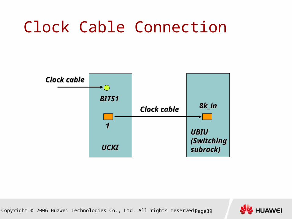
Clock Cable Connection
BITS1BITS1
11
UCKIUCKI
UBIUUBIU(Switching (Switching subrack)subrack)
8k_in8k_inClock cableClock cable
Clock cableClock cable

Copyright © 2006 Huawei Technologies Co., Ltd. All rights reserved. Page40
2. UAG Hardware Structure
2.1 UAG Logical Structure
2.2 UAG Hardware Structure
2.3 UAG Switching Subsystem
2.4 UAG OAM Subsystem
2.5 UAG Clock Subsystem
2.6 UAG Interface Subsystem
Contents
Copyright © 2006 Huawei Technologies Co., Ltd. All rights reserved. Page41
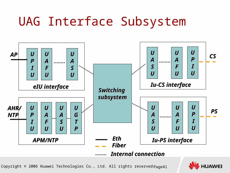
UAG Interface Subsystem
UUPPIIUU
UUAAFFUU
UUAASSUU
Switching Switching subsystemsubsystem
eIU interfaceeIU interface
EthEthFiber Fiber
UUAASSUU
UUAAFFUU
UUPPIIUU
UUPPIIUU
UUAAFFUU
UUAASSUU
UUAASSUU
UUAAFFUU
UUPPIIUU
Iu-CS interfaceIu-CS interface
Iu-PS interfaceIu-PS interface
APAP
AHR/AHR/NTPNTP
UUGGTTPP
CSCS
PSPS
Internal connectionInternal connection
APM/NTPAPM/NTP

Copyright © 2006 Huawei Technologies Co., Ltd. All rights reserved. Page42
UAG Interface Subsystem
UPIU
UAFU
UASU
UGTP
eIuinterface
Iu-CS, Iu-PSinterface
Data bus
High-speedserial port
Conf.network port
UEEC/UEFC
UAIC
Copyright © 2006 Huawei Technologies Co., Ltd. All rights reserved. Page43
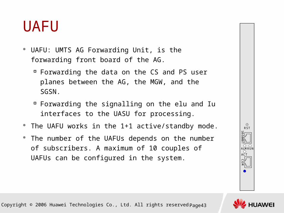
UAFU UAFU: UMTS AG Forwarding Unit, is the
forwarding front board of the AG.
Forwarding the data on the CS and PS user planes between the AG, the MGW, and the SGSN.
Forwarding the signalling on the elu and Iu interfaces to the UASU for processing.
The UAFU works in the 1+1 active/standby mode.
The number of the UAFUs depends on the number of subscribers. A maximum of 10 couples of UAFUs can be configured in the system.
RST
CO
M1
0/1
00
BT
ALMRUN
ACT

Copyright © 2006 Huawei Technologies Co., Ltd. All rights reserved. Page44
UPIU
UPIU:
The back board of UFCU/UAFU.
Providing Ethernet or Giga bit/s or ATM
interface by using different PMC board:
UEEC: 10M/100M Ethernet port;
UEFC: 1000M Ethernet( Giga bps) port;
UAIC: ATM optical port.
LNK
RXTX
M/S-LINK
ACT
ALMRUN
P0
P1
P2
P3
P0
P1
P2
P3
UEEC
UEFC/
UAIC

Copyright © 2006 Huawei Technologies Co., Ltd. All rights reserved. Page45
UASU UAFU: UMTS AG Signal Unit, is the service
signal processing board. Handling of CS and PS call signalling;
RNC agent;
AP management;
MSISDN access control;
resource management.
The UASU works in the 1+1 active/standby mode. The number of the UAFUs depends on the number of subscribers.
RST
CO
M1
0/1
00
BT
ALMRUN
ACT

Copyright © 2006 Huawei Technologies Co., Ltd. All rights reserved. Page46
UGTP
UGTP: GTP Processing Unit
Processes the GTP user plane signalling, and
stores and manages the user PDP contexts.
NTP function;
IPsec function.
RST
CO
M1
0/1
00
BT
ALMRUN
ACT

Copyright © 2006 Huawei Technologies Co., Ltd. All rights reserved. Page47
Contents
1. UAG Overview
2. UAG Hardware Structure
3. UAG Signalling and Data Flows

Copyright © 2006 Huawei Technologies Co., Ltd. All rights reserved. Page48
Iu-CS Signalling Flow
UUPPIIUU
UUAAFFUU
UUAASSUU
APAP UUBBIIUU
UURRCCUU
UUPPIIUU
UUFFCCUU
UUBBIIUU
UURRCCUU
UUAASSUU
UUPPIIUU
UUAAFFUU
MSC ServerMSC Server

Copyright © 2006 Huawei Technologies Co., Ltd. All rights reserved. Page49
Iu-CS Data Flow
UUPPIIUU
UUAAFFUU
UUAASSUU
APAP UUBBIIUU
UURRCCUU
UUPPIIUU
UUFFCCUU
UUBBIIUU
UURRCCUU
UUAASSUU
UUPPIIUU
UUAAFFUU
MGWMGW

Copyright © 2006 Huawei Technologies Co., Ltd. All rights reserved. Page50
Iu-CS Signalling Flow
UUPPIIUU
UUAAFFUU
UUAASSUU
APAP UUBBIIUU
UURRCCUU
UUPPIIUU
UUFFCCUU
UUBBIIUU
UURRCCUU
UUAASSUU
UUPPIIUU
UUAAFFUU
SGSNSGSN

Copyright © 2006 Huawei Technologies Co., Ltd. All rights reserved. Page51
Iu-PS Data Flow
UUPPIIUU
UUAAFFUU
UUAASSUU
APAP UUBBIIUU
UURRCCUU
UUPPIIUU
UUFFCCUU
UUBBIIUU
UURRCCUU
UUAASSUU
UUPPIIUU
UUAAFFUU
SGSNSGSN

Copyright © 2006 Huawei Technologies Co., Ltd. All rights reserved. Page52
APM/NTP Signalling Flow
UUPPIIUU
UUAAFFUU
UUAASSUU
APAP
APM flowAPM flow
UUPPIIUU
UUAAFFUU
UUGGTTPP
NTPNTP
NTP flowNTP flow

Copyright © 2006 Huawei Technologies Co., Ltd. All rights reserved. Page53
Summary
UAG is consist of OAM subsystem, ATM switching
subsystem, clock subsystem, NTP subsystem, data
forwarding subsystem and signalling processing
subsystem.

Thank youwww.huawei.com