![Tokyo, Japan, 4-5 February 2013 Activities of FG-M2M Hideo Himeno FG-M2M WG3 leader NEC Corporation h-himeno[at]bc.jp.nec.com ITU Workshop on E-health.](https://static.fdocuments.in/doc/165x107/55154083550346c77d8b5f37/tokyo-japan-4-5-february-2013-activities-of-fg-m2m-hideo-himeno-fg-m2m-wg3-leader-nec-corporation-h-himenoatbcjpneccom-itu-workshop-on-e-health.jpg)
0PREDICTION 0STATE SHIP ROLL DAMPING- OF THE · PDF fileNo. 239 September 1981 Prediction of...
87
No. 239 September 1981 0PREDICTION OF 00 SHIP ROLL DAMPING- 0STATE OF THE ART Professor Yoji Himeno This research was carried out In part under the Naval Sea Systems Command General Hydrodynamics Research Program@ SubproJect SR 009 01 01, administered by the Naval Ship Research and Devolopment Center Contract No. N00014-79-C-024 4 It was also supported by the Japan Shipbuilding Industry Foundation L T A a p anSibidn o 4 TIlE DEPWTMErf 4 R u-r" 4 JURE AND MARINE ENGINEERING THE UNIVERSITY OF MICHIGAN OLLEGEOF ENGINEERING -- " 82 03 2 2 1 0-3
Transcript of 0PREDICTION 0STATE SHIP ROLL DAMPING- OF THE · PDF fileNo. 239 September 1981 Prediction of...

No. 239September 1981
0PREDICTION OF00 SHIP ROLL DAMPING-0STATE OF THE ART
Professor Yoji Himeno
This research was carried out In partunder the Naval Sea Systems Command
General Hydrodynamics Research Program@SubproJect SR 009 01 01, administered by the
Naval Ship Research and Devolopment CenterContract No. N00014-79-C-024 4
It was also supported by the
Japan Shipbuilding Industry Foundation
L T A
a p anSibidn o 4
TIlE DEPWTMErf 4R u-r"
4 JURE AND MARINE ENGINEERING
THE UNIVERSITY OF MICHIGAN
OLLEGEOF ENGINEERING
-- " 82 03 2 2 1 0-3

UNCLASSIFIEDSFCUnlITY CLA351FICATION OF THIS PAGE (07h.n Date Ene.ed)
REPORT DOCUMENTATION PAGE READ INSTRUCTIONSBEFORE CO LIPLFTTN* FORM.1. REPORT NUM8E' O. GOVT ACCESSION NO. 3. RECIPIENT'S CATALOG NUMOER/f) . / 'j ,z 2.
4. TITLE (and Sub(tIle) S. TYPE OF REPORT & PERIOD COVERED
Prediction of Ship Roll Damping --
A State of the Art Final6. PERFORMING ORG. REPORT NUMBER
2397. AUTHOR(a) 6. CONTRACT OR GRANT NUMBER(a)
Yoji Himeno
N00014-79-C-0244
9. PERFORMING ORGANIZATION NAME AND ADDRESS 10. PROGRAM ELEMENT. PROJECT, TASK
Nav Arch & Mar Engr, The Univ. of Michigan
2600 Draper 61153N R02301Ann Arbor, MI 48109 SR 023 01 01
II. CONTROLLING OFFICE NAME AND ADDRESS 12. REPORT DATE
David W. Taylor Naval Ship R&D Center September 1981(1505) I3. NUMBER OF PAGES
Bethesda, MD 20084 8614. MONITORING AGENCY NAME & ADORES(It dtlteenl from Contolllng Ofl*.) 15. SECURITY CL.ASS. (.1 4hil report)
Office of Naval Research UNCLASSIFIED800 N. Quincy St.Arlington, VA 22217 ISa. OECLASSIFICATIONOOWKGRAOING
SCHEDULE
,6. DISTRIBUTION STATEMENT (of t i Report)
APPROVED FOR PUBLIC RELEASE: DISTRIBUTION UNLIMITED
17. DISTRIBUTION STATEMENT (of the batract entered In Block 20. it di feret from Repo")
IS. SUPPLEMENTARY NOTES
Sponsored by the Naval Sea Systems Command General Hydromechanics Research (GHR)Program administered by the David W. Taylor Naval Ship R&D Center, Code 1505,Bethesda, MD 20084.
1s. KEY WORDS (Continue on rerse sIde. i n.cesary and Ident y by block nhmber)
SHIP MOTIONSROLL DAMPINGSEPARATION
20. ABSTRACT (Conttnue on reer ee ide If neceseary end identify by block numbe,)
Various methods for predicting the roll damping of a ship at forward speedis discussed. In particular, a simple method and a component analysis are de-scribed. The component analysis assumes that the damping is composed of frictiondamping, eddy damping, lift damping, wave damping, normal-force damping of bilge,keel, hull pressure damping due to bilge keels, and wave d~mping of bilge keels.Formulas for these components are derived from theoretical and experimental con-siderations. A listing of a computer program used to compute roll damping is in-cluded as an Appendix.
DD , , 1473 EDITION OF I NOV 6S S OSOLETIAM 731473 UNCLASSIFIED e.SECURITY CL.ASSIFICATION OF THIS PAGE (whe Oat Enteed

No. 239September 1981
Prediction of Ship Roll Damping --
State of the Art
Professur" Yoji Himeno
University of Osaka Prefecture
This research was carried out in partunder the Naval Sea Systems Command
General Hydrodynamics Research Program,Subproject SR 009 01 01, administrated by the
Naval Ship Research and Development CanterContract No. N00014-79-C-0244
it was also supported by the
Japan Shipbuilding Industry Foundation
44Ap 8 Department of Naval Architecture4L A and Marine Engineering
- College of EngineeringThe University of Michigan
Vil Ann 1abor, Michigan 48109

CONTENTS
Page
Foreword v
Acknowledgement vil
Nomenclature ix
Tables and Figures xiii
1. Introduction 1
2. Representation of Roll Damping Coefficients 4
2.1 Nonlinear Damping Coefficients2.2 Equivalent Linear Damping Coefficients2.3 Extinction Coefficients
3. Prediction of Roll Damping: I. Simple Method 11
3. 1 Watanabe-Inoue-Takahashi Formula3.2 'fasai-Takaki's Table
4. Prediction of Roll Damping: II. Component Analysis 19
4.1 Definition of Component Damping4.2 Friction Damping4.3 Eddy Damping4.4 Lift Damping4.5 Wave Damping
4.6 Bilge-Keel Damping4.7 Normal-Force Damping of Bilge Keel4.8 Hull-Pressure Damping Due to Bilge Keels4.9 Wave Damping of Bilge Keel4.10 Prediction of Total Damping4.11 Comparison with Experiment
5. Treatment of Nonlinear Roll Damping in Prediction ofRoll Motion 50
6. Conclusion 53
References 54
Appendix: An Example of Computer Program on Ship Roll Damping 59
,(, j i

FOREWORD
The theory for predicting the motions of a ship in a seaway is one of the
triumphs of research in ship hydrodynamics. Given a rather small amount of
information about a ship and the seaway, one can predict heave and pitch motions
to a remarkable degree of accuracy without recourse to model tests or empirical
data. Lateral-plane motions, sway and yaw, can also be predicted with reasonable
accuracy.
However, when one tries to predict roll motion, one realizes what good luck
we have had in analyzing heave, pitch, sway, and yaw: These are riot sensitive
to the effects of fluid viscosity. Roll motion is extremely sensitive to viscosity
effects, especially to viscosity - induced flow separations. In addition, roll
motion is strongly influenced by the presence of bilge keels, which are difficult
to analyze even by the classical methods of hydrodynamics of an ideal fluid.
During the 1978-79 academic year, our Department was fortunate in having as
a visiting scholar Professor Y. Himeno of the University of Osaka Prefecture. He
is well-known in Japau for his research on viscous-fluid problems of ship hydro-
dynamics, and the De)artment of which he is a member is distinguished for its
research on ship roll damping.
Therefore I was especially pleased when he agreed to my request that he
prepare a report describing the state of the art in predicting roll damping.
As in many areas of naval architecture, Japan is in the forefront in developing
practical procedures for predicting ship roll damping. Professor Himeno has been
closely associated with these developments.
As he makes clear in this report there are many aspects of this problemthat have not yet been adequately analyzed. However, iL the great tradition of
Japanese naval architecture research, theory is used as far as possible, and the
gaps are filled with empirical information. More researc& is needed, but a
usable procedure for predicting roll damping ig describe.
In the appendix, a computer program is presented for predicting roll damping.
This program from Osaka Pretecture University was tested at The University of
Michigan by having an undergraduate compile it and use it. The information pro-
vided in the Appendix, together with the comments built into the prograr, were
_V-

- .- - ',m g
sufficient for this student to use the program.
T. Francis OgilvieDepartment of Naval Architecture
and Marine EngineeringThe University of Michigan
A
A
I:
I II

ACNOWLED ENT
This survey has been prepared during the author's stay at The University
of Michigan for a year. The author would like to express his heartfelt appre-
ciation to Professor T. Francis Ogilvie, Professor William S. Vorus, Dr. Nabil
Daoud, Dr, Armin W. Troesch and Mr. John P. Hackett for their valuable advice,
discussions and encouragement.
The author also feels grateful to Professor Norio Tanaka and Dr. Yoshiko
Ikeda ac University of Osaka Prefecture.
-vii- I

NOMENCLATURE
[Note: Numbers in parentheses indicate equations where more informationcan be found about the quantity listed.]
AR Wave-amplitude ratio (See Fig. 4.6)
A Inertia coefficient in roll equation of motion (2.1)
Z Extinction coefficient (2.15)
B Ship beam
BE Damping coefficient component: bare-hull eddy making (4.1)
BF Damping coefficient component: bare-hull skin friction (4.1)
BL Damping coefficient component: lift (due to forward speed) (4.1)
BW Damping coefficient component: bare-hull wave making (4.1)
BBK Damping coeffic -. 'omponei .: total of bilge-keel pressure
effects (4.2)
BBKH Damping coefficient component: hull pressure change due to bilge
keels (4.1)
BBKN Damping coefficient component: bilge-keel normal pressure (4.1)
BBW Damping coefficient component: bilge-keel wave making (4.1)
B- E i lnear damping coefficient (2.5)
HB Poll-damping term in equation of motion (2.1)
Bj Coefficients in expansion of Be , j = 1,2,... (2.2)
b Extinction coefficient (2.15)
bBK Width of bilge keel
bI Effective width of bilge keel (4.20)
CB Hull block coefficient
CD Drag coefficient (4.17) (See Fig. 4.9)
Cp Pressure-difference coefficient (4.7)+
C+ C in front of bilge keel
C ~p behind bilge keel
C, Pestoring-force coefficient in equation of motion (2.1)
c Extinction coefficient (2.15)
d Ship draft
Fn Froude nwmber
f Empirical coefficient giving velocity increment at the
bilge circle (4.20)
24 Metacentric height (restoring-moment lever arm) (2.1)
g Acceleration of gravity
-ix-
- -.----------- ____ -- ____ __

H B/2d (4.7)0
KG Distance from keel to center of gravity of ship
k Reduced frequency, wL/U
L Ship length
kBK Length of bilge keel
0 Roll excitation moment (2.1)
N "N-coefficient," A/ 2 (2.19)
N1 0 Value of N for *A - 100 (2.20)
O Origin of coordinates
OG Distance downward from origin to center of gravity (4.5)
R Bilge radius of hull
r Mean distance from center of gravity to bilge keels (4.5)
rma x ximum distance from roll axis to hull surface (4.7)
So Width of distribution of C on hull
Tn Natural period of roll (2.4)
t Time variable
U Forward speed of ship
W Weight of ship
(I BI/2A (2.4)
j 5 e Be/ 2A4 (2.9)iB l B~i A ( 2.4 )
y B3 /A (2.4)
60 On-i - @n (2.15a)
A Radiation wave amplitude (Fig. 4.6)
X Scale ratio of ship to model
V Kinematic viscosity of water
d w2 d/g (4.15)
p Density of Water
a Area coefficient of a cross-section of the hull
T Uk/g (4.15)
Roll angle (2.1)
A Amplitude of roll motion (2.1)
W Frequency (rad/sec)
ii 2w/Tn = C7A. (2.4)
-L-

Special Notations:
V Displacement volune of ship^ Indicates nondimensional form of quantity.
0 Isubscript] indicates value at zero forward speed.
indicates 2-D value for a cross-section of hull.
-xi-
I=
r1III
i -xi-

TABLES AND FIGURES
V "age
Table
3.1 Particulars of Models 153.2 Damping coefficients of 2nd-order approximation 163.3 Damping coefficients of 3rd-order approximation 17
3.1 Bilge-keel efficiency in Watanabe-Inoue Method 133.2 Effect of advance speed on roll damping force 143.3 Roll damping coefficients of CS - 0.71 ship form 184.1 Frictional component of roll damping force 234.2 Eddy component of roll damping force for after body snction
with area coefficients of 0.43 254.3 Eddy component of roll damping force for midship section
with area coefficient of 0.997 254.4 Effect of advance speed on eddy component 274.5 Sum of eddy and lift components of roll damping force 294.6 Radiation wave amplitude for Lewis form cylinder 304.7 Effect of advance speed on wave component 324.8 Effect of advance speed on wave and lift components 334.9 Drag coefficient of bilge keel 354.10 Component due to normal force on bilge keel 374.11 Effect of advance speed on drag coefficient of bilge keel 384.12 Fujino's prediction for normal force on bilge keel 384.13 Pressure distribution on hull induced by bilge keel 404.14 Effect of bilge keel on roll damping coefficient at zero
Froude number 414.15 Radiation wave amplitude for cylinder with bilge keels 43A. 16 Schematic view of roll damping components with advance speed 454.17 Effect of roll frequency on roll damping components 454.18 Nonlinear effect of roll damping coefficients 464.19 Comparison of roll damping coefficient between measured and
estimated with advance speed 484.20 Roll damping coefficient for cargo ship model at forward
speed 484.21 Comparison between measured and estimated roll damping
coefficient at zero Froude number 494.22 Roll damping coefficient for cargo ship model Fr - 0.2 49
-xiii-
1. INTRDDOCTION
roll motion is one of the most important responses of a ship in waves.
The roll motion of a ship can be determined by analyzing various kinds of
moments acting on thne ship, virtual and actual mass moments of inertia, roll
damping moment, restoring moment, wave excitation and other momumts caused by
other modes of ship motion. Among them, the roll damping moment has been con-
sidered to be the most important term that should be correctly predicted. It
is needed not only at the initial stage of ship design to secure the safety
of a ship, but also to obtain a better understanding of ship motions in waves.
Since the age of W. Froude, a number of theoretical and experimental
works has been made concerning the predictions of roll damping and rol 1 mo-
tion of ships. The recent d.volopment of the "Strip Method" has made it pos-
sible to calculate almost all the terms in the equations of ship motions in
waves with practical accuracy, except for the roll damping. The necessity
of obtaining the roll damping of ships has been pointed out in the recent
*recommendations of the Seakeeping Committee of the International Towing Tank
Conference (ITTC) Notwithstanding these efforts, it seems that a complete
solution of this problem has not yet been rcached.
Difficulties in predicting the roll damping of ships arise from its
nonlinear characteristics (due to the effect of fluid viscosity) as well as
from its strong dependence on the forward speed of ship. Moreover, the fact
that these various effects have influences on the value of roll damping that
are of the same order of magnitude makes the problem even more complicated
in the absence of bilge keels.
After the classical works by Bryan [ 1 ] and Gawn ( 2 1, we can recog-
nize -an epochmaking period a couple of decades ago in the history of research
on roll damping. Experiments on bilge keels by Martin [ 3 ], Tanaka [ 4 3,
and Kato ( 5 3, theoretical works on the vo.rtex flow near bilge keels by
Sasaji a ( 6 3, consideration of hull-friction damping by Kato [ 7 1, and
study if the surface-tension effect by Ueno [ 8 1, all of these works ap-
pear in this period.
Furthenior3, we can cite here Hishida's theoretical studies [ 9 3 on the
wavemak.Lng roll damping due to hull and bil.ge keels and flanaoka's mathematical
jL-1-

-2-
formulation [10] for the wave system created by an oscillatory motion of
an immersed flat-plate wing with low aspect ratio. Also, an extensiveseries of free-roll tests at zero ship speed for ordinary ship hull forms
was carried out by Watanabe and Inoue [11] and tests at forward speed by
Yamanouchi [12]. Some of the results of these works have often been used
even up to the present time or have given background to recent works. This
fact cannot but remind us again of the difficulty of treating the ship roll-
damping problem rigorously.
It can be said that the recent works started about a decade ago, mainly
associated with the experimental check of the accuracy of the strip methiod.
Much data on radiation forces acting on ship hull, including roll damping,
have been accumulated through the forced oscillation tests carried out by
Vugts (13], Fujii and Takahashi [14], Takaki and Tasai [15], and Takezawa
et al. (16].
These experiments have clarified that there are still considerable dif-
ferences between measured values of roll damping and those predicted by ex-
isting methods. In this period much effort has also beei Tuae for obta-ining
snip roll damping, for example, works by Bolton [17], Lofft (18), and
Lugovski et al. [19], concerning the effect of bilge keels, Gersten's studies
[20] on the viscous effects, and free-roll experiments by Takaishi et al.
(21) and Tanaka et al. [22].
Moreover, what should be noted here is the extensive and systematic works
in Japan that have recently been carried out through the cooperation of the
Japan Shipbuilding Research Association, espe.uially in the Coomittees of
SRl08, succeeded by SR125, 131 and 161 [23]. In the prediction method of
ship roll damping considered there, damping is divided into several com-
ponents, for instance, friction, eddy, lift, wave, and bilge-keel components.
Then the total damping is obtained by simzing up these component dampings pre-
dicted separately. IThis attempt appears to have had a certain success for
ordinary ship hull forms.
The objective of this article is to describe the present state of the
art in these recent attempts as well as other existing formulas for ship roll
damping. Furthermore, for convenience in ship design, it is intended that
.. . . .... ..... _ . .. _ _

-3-j
the available expressions and formulas should be described in full detail as
much as possible, so that their values can be calculated promptly once the
particulars of a ship are given.
In Chapter 2 the various methods of representation for roll damping
coefficients and their relationships are stated and rearranged in terms of an
equivalent linear damping coefficient. Then, for prediction methods of roll
damping, simple methods are introduced in Chapter 3, including the use of data
from a regression analysis of model experiments. In Chapter 4, the newest
treatment for component dampings is stated, and available formulas for each1%component are fully described there. Comparisons are made of measured and pre-
dicted total damping, which is the sum of the component dampings.
Chapter 5 concerns the prediction methods Ror ship roll motion. However,
it is not the full present state of the art. The description is limited to
the problem of how to use the formulas of nonlinear roll damping in order to
obtain the solution of the roll equation of motion in regular or irregular
sea. Finally an example of a FORTRAN statement of a computer program for the
component dampings is given in the Appendix.

i2. REPRESENTATION OF ROLL DAPIPING COEFFICIENTS
Many ways of representing roll damping coefficients have been used, de-
I pending on whether roll damping is expressed as a linear or nonlinear form,
r- which form of the non-dimensional expressions is to be used, and by whatj experimental method its value was measured, for instance, forced-roll test
or free-roll experiment. Some of the expressions most coimonly used are
introduced here and the relationships among them are reviewed and rearranged I
in terms of a linearized damping coefficient.
2.1 Nonlinear Damping Coeffitient s
The equation of roll motion has recently been expressed as a three-degree-
of-reedom form, including sway and yaw motions simultaneously. However, in
order to limit the discussion here to the problem of nonlinear roll damping," we can write down the equation of the toll motion of a ship in the following
simple single-degree-of-freedom form:J4-$ B4 ( + C4,4 M(w t) .(2.1)
In Eq. (2.1), p represents the roll angle (with the amplitude 4 A3' A the
virtual mass moment of inertia along a longitudinal axis through the centerof gravity and Co the coefficient of restoring moment, which is generally
equal to W'GM (W the displacement weight of the ship and GM the metacentric
height). Furthermore, N stands for the exciting moment due to waves or
external forces acting on the ship, wu the radian frequency and t the time.
Finally, B4 denotes the roll damping moment, which is now considered.
Although only the main terms of roll motion have been taken into account
in Eq. 22.1,, coupling terms being neglected, it can be said that Eq. (2.1)
almost corresponds to that of three degrees of freedom when we consider the
wave excitation term M as the Froude form with a coefficient of effective
wave slope. This is because the concept of the effective decrease of wave
slope turns out, after Tasai's analysis [24], to correspond to the effect of
thie sway coupling terms.
We can express the damping mnme't B, as a series expansion of $
and jjin the form

-5-
B)+B 2 J P + 2. (2.2)
which is a nonlinear representation. The coefficients B1 , B2 , ... in
Eq. (2.2) are considered as constants during the motion concerned. In other
words, these values may possibly depend on the scale and the mode of the
motion, for instance, on the amplitude A and the frequency W when the
ship is in a steady roll oscillation.
Dividing Eq. (2.1) by A , we can obtain another expression per unit
mass moment of inertia:
2t + +y +Y n = m (It), (2.3)
whereBa B2 B3
V
A A A
(2.4)
Wn ra T ,mj ~2T n AOt
In Eq. (2.4), the quantities w. and Tn represent t-he natural frequency
and the period of roll, respectively.
A term of the form $/i$l might be added to the right-hand side of
Eq. (2.2). This term corresponds to the effect of surface tension at water
level of the ship hull. Ueno f 8 ] investigated this effect and concluded
that the surface tension might cause a considerable error in the values of
the damping coefficients when a small model is used in small amplitude of
oscillation. However, this effect is not considered hereafter, because the
surface tension depends strongly on thn condition of the painted surface of
the model hull as well as on that of the water surface, and because it can
be neglected in the case of roll amplitude with moderate magnitude for a
ship model of ordinary size.
To obtain the values of these coefficients of nonlinear damping directly
through a steady-state forced-roll experiment, in which 4 A and w are
specified, we would probably need numerical techniques to fit the solution
of the assumed equation to the measured data. Such an attempt does not seem

-6-
to have been done. Instead, the usual way that has been taken is to assume
some additional relations concerning, say, energy consumption, linearity of
damping and its independence of 4 A r which will be described later.
2.2 Equivalent Linear Damping Coefficients
Since it is difficult to analyze strictly the nonlinear equation statedr in the preceding section, the nonlinear damping is usually replaced by a
certain kind of linearized damping as follows:
= Be$ (2.5)
The coefficient Be denotes the equivalent linear damping coefficient.
Although the value of Be depends in general on the amplitude and the
frequency, because the damping is usually nonlinear, we assume Be is
constant during the specific motion concerned.
There are several ways to express the coefficient B in terms of thee
nonlinear damping coefficients BI , B2 and so on. The most general wayis tu atjume that th~e energy loss due to damping during a half cycle of rollAis the same when nonlinear and linear dampings are used (24]. If the motirn
is simple harmonic at radian frequency d
Be = Bl+ 8 wAB 32+ (2.6)
For more general periodic motion, Eq. (2.6) can be derived by equating the
first terms of the Fourier expansions of Eqs. (2.5) and (2.2) [15].
For convenience in analyzing the equations of lateral motions, the
nondimensional forms of these coefficients are defined as follows:
-V '=V2- 'l for i=1,2,3 (2.7)pVB2 P2g 2g
where p , V and B stand for fluid density, displacement volume and
breadth of ship, respectively. Then Eq. (2.6) takes the following nondimen-
sional form:

-7-
B 8 + w(2.8)
Corresponding to Eq. (2.3), we can define an equivalent linear damping
Akcoefficient a. Be/2A per unit mass moment of inertia:
= -- 4+i A +i,4 04 Y . (2.9)
Since these coefficients still have dimensional values (except for the second,
F), the following dimensionless forms are often used, especially for the
linear terms ae and a
2ae 2ca1 e rj' . a - (2.10)
In case of irregular roll motion, there is another approach to lineariza-
tion of the roll damping expression. After the works of Kaplan (26] and
others [27] (23], we assume that the difference of the damping moment between
its linearized and nonli-near forms can be minimized in the sense of the least
squares method. Neglecting the term B3 for simplicity, we define the discrepancy
6 in the form:
6 B1 4;+ B2 -4 (Be;) (2.11)
Thrq we can miniuze E{6 2}, the expectation value of the square of 6
during the irregular roll motion, assuming that the undulation of the roll
angular velocity, * is subject to a Gaussian process and that the coeffi-
cients Be , B and B2 remain constant:
(62 -- -2 (-2B 2E{; 0 (2.12)
aBe 1 e 2
After some calculations we can reach the form
Bei= Bi+8 .B , (2.13)
where the factor a. represents the variance of the angular velocity
It is claimed in recent works [23] that this form is useful for analyzing
roll behavior in irregular seas.
-8-
Moreover, as an unusual way of linearization, we can equate the nonlinear
expression to the linear one at the instant when the roll angular velocity
takes its maximum value during steady oscillation:
d Be = B1 + W4 AB 2 (2.14)
This form seems to correspond to a collocation method in a curve-fitting
problem, whereas Eq. (2.6) corresponds to the Galerkin approach. Since there
is a difference of about 15% between the second terms of the right hand sides
of Eqs. (2.6) and (2.14), the latter form may not be "alid for the anialysis
of roll motion. But it may be used as a simple way of analyzing forced-oscil-
lation test data to obtain the values of these coefficients promptly from
the time history of the measured roll moment.
However, the most common way to obtain these nonlinear damping coeffi-
cients through forced oscillation tests is, first, to find the equivalent
linear coefficient Be in Eq. (2.5) by assuming that the forced-roll-test
system is subject to a li.near equation, and, second, to fit Eq.(2.6) to the
Be values obtained by several test sequences with the amlitude .A varied.
Then we can obtain the values of these damping coefficients, B I , B2 and
so on, which are independent of the amplitude of roll oscillation.
It should be noted here that this condition, the independence of
amplitude, was not stated when we derived Eq. (2.6). Therefore we might
obtain different values of the coefficients from the original ones if the
coefficients, especially B , should depend on the amplitude, particularly2
in the presence of bilge keels. We should keep these things in mind when we
use a formula like Eq.(2.6).
2.3 Extinction Coefficients
A free-roll test is probably the simplest way to measure roll damping
of ship or model. In a model test, sway and yaw motions are usually restrained
to avoid the effect of the horizontal motions. On the other hand, heave
and pitch motions are often kept free to avoid the error due to the sinkage
force in the presence of forward speed, although it is of course desirable to
make the vertical motions as small as possible. The roll axis is usually
taken through the center of gravity of the model, the radius of gyration of

-9-
the model is adjusted to the value of the actual ship considered, and the
restoring moment lever GM is also measured through a static inclination
test.
In a free-roll test, the model is roiled to a chosen angle and thenreleased. The subsequent motion is measured. Denote by ln the absolute
value of roll angle at the time of the n-th extreme value. The so-called
extinction curve expresses the decrease of *n as a function of mean roll
angle. Following Froude and Baker, we fit the extinction curve by a third-degree polynomial : i
Al = alm +b 2 +c4 3 (deg.) , (2.15)
whe reAwe = -n-i - n, (215a)
4'm = - +l n]/2 . (2.15b)
In
The angles are usually measured in degrees in this process.
The coefficients a-, b and c are called extinction coefficients. The
relation between these coefficients and the damping coefficients can be
derived by integrating Eq. (2.1) without the external-force term over the time
period for a half roll cycle and then equating the energy loss due to damping
to the work done by restoring moment. The result can be expressed in the
form
4 C B 8 lp" B + 4 2lpm B 3 (rad) . (2.16)
Comparing Eq. (2.16) with Eq. (2.15) term by term, we can obtain the relations
2180 4 Wn 4 (2.17)
3180 2 3,,n 37-) C o- cB 3 " 0 nY
iT v 8
I.

-3.0-
It should be noted here again that the condition for the validity of Eq.
(2.17) is that the coefficients B 1 , B2 , and cc , B.....should be inde-
pendent of the roll amplitude. As we can see in the later chapters, the
effect of bilge keels appears mainly in the term B, , and, further, the -
value of D 2 varies with roll amplitude. In such a case, Eq. (2.17) will not
remain valid. Only the part of B2, which is independent of the amplitude
is related to the coefficient b. The other part of B2 that is inversely
proportional to the amplitude will apparently be transferred tc the coeffi-
cient a , and the part proportional to the amplitude will appear in c. In
place of a term-by-term comparison, therefore, it will probably be reasonable
to define an equivalent extinction coefficient ae and to compare it with
the equivalent linear damping coefficient Be as in the form
ae = a+bm+ c - Be (2.18)
We are also familiar with Bertin's expression (25], which can be writ-
ten in the form
Ne (dcg.) (2.19) 1
The coefficient N can be taken as a kind of equivalent nonlinear expression,
and it has been called an "N-coefficient." As seen from Eq. (2.15),
N Wb + 0m (deg.) (2.20)
The value of N depends strongly on the mean roll angle *m ' so that its
expression is always associated with the 4 r value, being denoted as N 1 0
N20 and so on, where N10 is the value of N when Om 100, etc.

3. PREDICTION OF aLL DAMPING: I . SIMPLE METHOD
When the principal dimensions of a ship form are given, the most reli-
able way to obtain the roll damping of the ship at present time seems to be
to carry oat a model experiment. Since the scale effect of the damping is
considered to be associated mainly with the skin friction on the hull, which
makes a small contribution to total damping, the data from the model tests
can easily be transferred to the actual ship case by using an appropriate
nondimensional form of roll damping, for instance, Eq. (2.8).
If model-test data are not available, it is necessary to estimate the
roll-damping value by using certain kinds of prediction formula. There are
two different ways of estimation at present time. One is to obtain an empiri-
cal, experimental formula directly through the analysis of model tests on
actual ship forms. The other is to break down roll damping into several
components and then estimate the value by summing up the values of those
components individually predicted.
The latter is considered to be more rational, so that it has become the
recent trend of approach in Japan. To begin with, however, some examples of
the former approach are described in this chapter in order to know the mag-
nitude of ship roll damping easily.
3.1 Wataiiabe-Inoue-Takahashi Formula
A couple of decades ago, Watanabe and Inoue [11] established a formula
for predicting the roll damping of ordinary ship-hull forms at zero advance
speed in normal-load condition, on the basis of both an extensive series of
model tests and some theoretical considerations on the pressure distribution
on the hull caused by ship roll motion. Their original formula has been
modified slightly by them (28] so as to be applicable to a wider range of
ship forms, including ships w:,ith large values of block coefficient.
Takahashi [29] proposed a form of forward-speed modification multiplier
to be applied to the value at zero ship speed, thus expressing the advance-
speed effect on roll damping. We may call this approach the Watanabe--Inoue-
Takahashi formula.
-1-

-12-
This can be expressed in terms of an ecquivalent linear damping coeffi-
cient of the form
Be - Beo [l+0.8{1-exp(l-OFn)} n (3.1)
where Beo stands for the value of Be at zero ship speed. Its value can
be expressed in terms of the extinction coefficients a and b , as follows:
Beo 2aeA
= 2 nA(a+---b) (QA:deg). (3.2)
Furthernore these coefficients can be related to the values of the N-
coefficients N 10 and N 20 at the roll amplitudes A = 100 and 200
N 1 0 = b, N2 0 = +b (3.3)
100
and the virtual mass moment of inertia A can be calculated by the strip
method or otherwise determined through the approximate relationship of the
natural roll frequency to both the coefficient A and the restoring moment
of the ship.
The N-coefficients can be expressed after Watanabe and Inoue in the
form
IN n ) 1.) b 1E3( d2\ fB4 Ld0 1 - o 1+ - (3.4)
20 L4 64dJW'W'
where L,B and d represent ship length, beam and draft. The quantity
Ab denotes the area of the bilge keel at one side of the hull. The distance
Z is defined: d9. KG - , (3.5)
and the quantity f is a function of waterline area coefficient C :
4 6 4 1 Cw
m+. 2m+l 3m-+i 4m+l m -Cw

200 1.85
00
.80
150 -
275
1.7100
so .60
.45
.002 .003 .005 .01. .02 .03 .05 .1
b BK/ZBK (aspect ratio at bilge keel,
Figure 3.1. Bilge-keel efficiency i'i Watanabe-Inoue method

-].4-
The first square bracket on the right-hand side of Eq. (3.4) corresponds
to a kind of drag coefficient of nonlinear damnping. The coefficient n
and n20 stand for those of the naked hull at the roll amplitudes l0°
and 20' , expressed in the form
0.8 %d S0.03.. ... +(3 .7 )
1. i.I L j0.02
where C1 represents ship block coefficient. Finally, the quantity 0
corresponds to a certain efficiency of the bilge keels, the value of which
can be determined from Fig. 3.1, given by the authors themselves; as a function
ofapec ratio b/. of the bilae keel.or B Rn te, BI(
We can thus obtain the magnitude of the rot), damping easily once the
principal dimensions of a ship and its bilge keels are given. Since these
formulas were established on the basis of a rather large anount of experimental.
data, 4t can be hoped that they will offer a reasonable estimation of roll
damping in the early stage of ship design. As an example, the comparison of
T k ahashi '- formula with so-te e-sperimental data i shon in Fig. 2 .2. The
agteemen" seems to be acceptable in the ordinary range of ship speed.
0<
1.0 ...:Tachhashl 's foraula 0 aB/Ha so
a SRI08 contPiner ship,CO-O. 56,w0. 398, A-15 deg.
o Ser.Gt parent form,CB.0.7,1rO.496,OA.10deg"o Ser.bO parent fom,CB.0.s, -0..s3, O510deq.
0.0
0.0 0.1 0.2 0.3 rn
Figure 3.2. Effect of advance speed on roll damping force

-15-
T'he background of these formulas should also be mentioned. Eq. (3.2) can
be derived from Eq. (2.17), which represents the term-by-term comparison between
the coefficients B1 , 2 , ... and the extinction coefficients a , b
and c . For its validity, however, the assumptionsare needed that the
coefficients Bi and B2 take their values at w)wn and are constant, that
is, are independent of frequency and are not affected by the roll amplitude
A " These assumptions, especially the former, might cause a misprediction for
the ship rolling in a frequency range away from the ship natural frequency.
Therefore these formulas should be applied to the case of a normally
loaded ship, and theni only near the natural frequency, where ship rolling
usually becomes important.
3.2 Tasai-Takaki's Table
As a second example of a simple method, we cite the results of Tasai and
Takaki's experiment (23], which has recently been carried out for the purpose
of obtaining typical values of roll damping for ordinary ship hull forms. The
roll damping of four typical kinds of ship form was measured by forced-roll
test at specified values of both Froude number and the roll amplitude, with
frequency varied. The data obtained were fitted by regression analysis to1.I the forms of Eq. (2.8), including two- and three-term damping coefficients.Table 3.1 Particulars of Models
container~ cargo chip ore carri.er tanker
leigth Lpp(m) 3.00 3.00 3.00 3.00
breadth B (m) 0.4354 0.4783 0.493 0.4719
draft d (,m) 0.1628 0.1957 0.194 0.1828disp ment 121.61 199.84 233.4 220.57
CB 0.5717 0.7119 0.8243 0.8519
CM 0.970 0.9905 0.9975 0.9946
GM (M) 0.017 0.02174 0.050 0.06077
ER (i) -0.0425 -0.025 0.089 0.0993
KL/Lpp 0.239 0.2172 0.2356 0.2494
KS/B 0.382 0.3240 0.2602 O.2513
BK/Lpp 0.25 0.25 0.25 0.37
bByKB 0.0148 0.0159 0.0142 0.00869

-16-
Table 3.1 shows the principal dimensions of the models, and Tables 3.2
and 3.3 present the nondimensional values of the nonlinear damping coeffi-
cients, taken up to the second and third terms, respectively
Table 3.2 Damping coefficients of 2nd-order approximation
F\j\CE. ore carrig r tanker container cargo ship
0 0.00193 0.00161 0.00006 0
0 .05067 0.05180 0.05563 0.06993
0. 0.00281 0.00272
tB2 0.05975 0.05387
0.1 0 00276 0.00286 0.00156
B2 0 005696 6.04 702 0.05785
02 B0.00282!0.20 A
B2 0 .04752
0 B 0.00571 0.00368~0,25 SB,, 0.032. 0.04548
Bt 0.00 596_ _ --- ,__ _ __ I _
_ ___0,0 0.02851
As an example for the validity of these curve fittings, the comparison
with the experiment on the CB = 0.71 cargo ship model is shown in Fig. 3.3.
The agreement seems to be quite reasonable, even in the region of comparatively
large roll amplitude. Since the result concerns a typical ship form, it
should be quite useful frr the prediction of magnitude of ship roll damping
at the initial stage of ship design. It can be applied to other cases of
different ship form and ship speed by interpolating or extrapolating the values
in the tables.
What should also be noted here is the limitation on the application of
these tables. It is assumed that the damping coefficients B1 , B2 and
B 3 in Eq. (2.8) are constant for specified ship form anu Froude number. There-
fore the tables do not cover the case without bilge keels, in which wave
damping J.ght prevail and the magnitude of the nonlinear teznts might not be
so large.
i-

-17-
Table 3.3 Damping coefficients of 3rd-order approximation
F ore carrier tanker container cargo shipn COEs ________ _______ _______ _
0 .00308 0.00209 0 .00082 0 .00061
0 B2 0.03262 0.04168 0.03690 0.04908
B 3 0.12170 0.03877 0 .08474 0.08994
BI 0.00359 0 .00316
0.10 B2 0.04110 0.04453
B 3 0.07783 0 .03581
B1 0.00344 0.00374 0.00242
0.15 B2 0.04254 0.02531 0.03755B3 0.05524 0.09835 0.08755
B1 0.00332
0.20 B2 0.03551
B 3 0.05226
B1 1 0.00628 0.00389
B 0.02125 0.040330.25 B2
B, 0.03567 0.02206
B 0.00671
0.275 B2 0.01402
B3 0.05097
We have seaen a couple of examples of simple methods for predicting theorder of magnitude of ship roll damping. Other similar methods might also beavailable for that purpose. To improve the accuracy of the prediction method,however, we should consider the phenomenon of roll damping from a much morephysical and hydrodynamic point of view. In this sense, the concept ofcomponent damping, which will be described in the next chapter, will present
more fruitful results applicable toawider variety of cases.

3rd order approximation,
- -- - nd order approximationA
0.02 r o X A measured at 1.A.M.,
I Kynstho Univ.
10.-
J 0.02 00
Figure 3.3. Roll damnping coefficients of C5 0.71 Ship form.

4. P-EDICTION OF ROLL DAMPING: II. COMPONENT ANALYSIS
4.1 Definition of Component Damping
It has been pointed out since a couple of decades ago, as mentioned pre-
viously, that roll damping of a ship is caused by various kinds of fluid flow
phenomena, for instance, skin friction of the hull, eddy shedding from the
hull, free-surface waves, etc. It has also been noted that roll damping is
strongly affected by the presence of bilge -keels, rudder and appendages.
In recent days, the concepts of these effects have been considerably
clarified and research work on the individual effects has been carried out.
The objective of this chapter is to define all these effects from the recent =
point of view of the concept of component dampings and to describe available
prediction formulas for them.
To begin with, we assume that the total roll-demping coefficient for an
ordinary ship hull form can be divided into seven components, that is, friction,
eddy, lift and wave damping for naked hull, and normal-force damping of bilge
keels, hull-pressure damping due to bilge keels, and wave damping of bilge
keels. This assumption can be exyxr5sed in terms ot equivalent linear damping
coefficients of the form
Be = BF + B E + BL + BW + BBr.N + BBKH + BBM , (4.1)
or we can sum up the bilge keel terms,
Be = lk + %E ' BL + .+ BBK (4.2)
Although these coefficients are seemingly linear, their values may vary
with the roll amplitude *A and the frequency w . For brevity the effect
of appendages, except for rndder and bilge keels, is not considered here.
The rudder is assumd to be included in the main hull configuration.
We can define these component dampings as follows, neglecting or including
their mutual interactions:
Friction dampingS B is caused by the skin-friction stress on the hull
-19-

-20-
in roll motion, so that it may possibly be influenced by the presence of waves
and bilge keels.
The eddy damping BE stands for the nonlinear damping ( B2 f$,
caused by the pressure variation on the naked hull, excluding the effect of
waves and bilge keels. However it may appareatly include the linear term
B1 , which would be transferred from the nonlinear term B2 if a part of B2
were inversely proportional to the amplitude A. In the presence of ship
forward speed, eddy damping represents the nonlinear part of the lifting effect
of the hull itself in roll motion, whereas the linear part is defined as the
lift damping BL
The wave damping BW denotes the increment of the hull-pressure damping
due to the presence of free surface waves, so that it includes the interaction
between waves and eddies and between waves and lift. However, since these
interactions, will be very small, it will be almost linear.
Bilge keel damping BBK represents the increment of pressure damping due
tc the presence of a pair of bilge keels. This term consists of the following
three components: The normal-foice damping o! bilu ktgls BBk is due to
the normal force on the bilge keels themselves. The second is hull-pressure
damping due to bilge keels BBK H , which corresponds to the pressure change
on the hull when bilge keels are installed. Therefore this term stands for
an interaction between hull and bilge keels. The rest is the wave damping of
bilge keels B BKW Since the first two terms do not concern the free surface,
this term represents the change of values of BBKN and BBKH due to waves.
This term also includes interaction between the hull (with bilge keels) and
waves.
We have presented so many component dampings that it is natural to ask
which component is the most important. The answer is quite difficult because,
as will be seen later, almost all the components (except B F and B BKW) are
of the same order of magnitude for an ordinary ship hull form. This is the
very fact that has made the prediction of ship roll damping difficult.
The subdivision of roll damping, as stated above, may not always be based
on the hydzodynamic point of view but may stand rather on a practical basis
for convenience in predicting the roll damping and carrying out the -tnriments.

-21-
However, we can still note here some remarks on these components. The terms
BL , BW and BBKW can safely be treated as nonviscous damping, while the
others can be regarded as viscous damping.
Tangential dtress on the hull contributes only to the term BF . The
rest of the damping is caused by the normal stress, that is , the pressure on
the hull or on the bilge keels. The surface-wava effects appear mainly in theterms BW and BBKW * The other terms can be considered as free from waves,
although the term B also includes a small wave effect in its definition.
To distinguish linear damping from nonlinear damping is quite difficult
at this stage. Of course, the non-viscous dampings like BL and Bw can be
regarded as linear, but also some parts in the terms BF and BK might
be linear, due to their dependence on Reynolds number or the Keulegan-Carpenter
number. The forward-speed effect is included in all terms.
These characteristics will be much better clarified after the individual
prediction methods are described in the following sections. 1IIHereafter the subscript 0 represents the case of zero spcd, the suPex-iI
script the value in the cross-sectional plane. The roll axis passes through
the center of gravity unless otherwise stated.
4.2 Friction Damping
In predicting the value of friction damping, we ignore the effect of
waves and regard the ship hull form as an equivalent axisymmetric body, for
which the dimensions will, be defined later. Then the skin friction laws for
a flat plate in steady flow are applied to the roll motion of the body, as
shown by Kato [ 7 J, Takaki [30], and Schmitke [31].
We cite Kato's formula as an example. In the absence of forward speed,
Kato applied Blasius' formula for laminar flow and Hughes' formula for turbu-
lent flow to the peripheral boundary layer of a circular cylinder. Kato's
formula can be expressed in terms of an equivalent linear damping coefficient
as follows:
2r , 2 0 .3 60. 787PSr2V-\)j + 0.008 1 4 (_it (CA:rad.) (4.3)
-s -

-22-
where p and o represent density and kinematic viscosity of fluid. In Eq.
(4.3), the first term in the brackets gives the result for the case of laminar
flow, which is used for the naked model hull, while the second term givas
the modification for turbulent flow by Hughes' formula, applicable to both the
model hull with bilge keels and the actual ship hull. The quantities S and V
r s were originally defined as the surface area and the radius of the cylinder.
For the case of a ship hull, however, they represent the wetted surface area
and the average radius of roll, which can be expressed approximately by theformulas -
S = L(l.7d+CB-B) (4.4)
r . (0.887 + 0.145CB) - 2 .G (4.5)
The symbols L , d , B and CB represent length, draft, beam and block
I coefficient of the ship, respectively. The vertical distance from the originIto the center of gravity, OG , is measured downward as positive.
i Since in Kato's formula the friction damping coefficient does not include
the amplitude A in the case of laminar flow, the damping is apparently
I, linear. This is because the damping is originally defined as a nonlinear form
and then the nonlinearity is cancelled by the dependence of the coefficient
on the roll Reynolds number.
Recently Myrhaug and Sand [32] have carried out the boundary layer calcu-
lation on a rolling circular cylinder and obtained almost the same result as
Kato by solving a Stokes-type equation in case of laminar flow. Ikeda et al.
[33] have also found the same relationship between the Stokl -olution and
t1e Blasius formula applied to the unsteady flow. Further, theN have confirmed
the validity of Kato's formula in practical use, through the measurements ofthe velocity profile in the boundary layer on two-dimensional cylinders of
shiplike sections.
In the presence of forward speed, Schmitke (31] has applied the skin-
friction law of turbulent flow directly to the case of ship rolling, in a
manner similar to Kato's treatment. However, we here cite Tamiya's formula
[34] based on the more rigorous analysis of three-dimensional boundary layers

-23-
on rolling cylinder. It can ba expressed in the following simple form
U.
BE = BF (1'+4.1m (4.6)
where the constant 4.1 has been determined through experiments on elongated
spheroids in roll motion. The coefficient BF0 represents the friction damp-
ing at zero forward speed, which can be predicted by Kato's formula.
The Tamiya formula has been confirmed as giving a good prediction by
Ikeda et al. [35], who carried out the somewhat detailed calculation of the
three-dimensional turbulent boundary layer development on the axisymmetricbody in its roll motion. Fig. 4.1 shows a comparison of the frictional dampingas given by the prediction methods and by measurements on a spheroid model. Wecan observe that the Kato-Tamiya prediction method is in reasonable agreement
with the measurements.
o measured for ellipsoid model
A Kato's formula
b F Tamnya's formula
calculated by Ikeda et al.
000
0.0005 - -. -" 0
Sd=u 2d/g = 0.162
0.0
0.0 0.1 0.2 0.3 Fn
Figure 4.1. Frictional component of roll damping force
It has been claimed that this Kato-Tamiya method, Eq. (4.3) through Eq.
(4.6), can safely be applied to the case of an actual ship hull form, sincethe ratio of friction damping to total damping is usually quite small. The
exact treatment may be impossible theoretically and experimentally.

-24-
According to the above formula, the increment of frictional damping due
to snip forward speed is proportional to the speed. When the frequency tends
to zero at a finite speed, however, the BF value becomes infinity, because
of the dependence of the value B on the roll Reynolds number. This pointFQ
may be a problem to be studied.
It is noted that the scale effect is quite large, since, at the correspond-
ing speed and the frequency, the non-dimensional value of the friction damping
is almost inversely proportional to X0 .75 where X represents the scale
ratio of the ship to the model. Therefore the value for the actual ship becomes
1/20 ^ 1/30 times that for the model, so that we can safely ignore the friction
damping of the actual ship.
4.3 Eddy Damping
In the absence of ship speed, this component is caused by flow separation
at the bottom of the ship hull near stem and stern or at the bilge circle near
the midship portion. The pressure drop in the separation region gives rise tothis damping. Since early times, this has been treated in a manner similar to
that for the drag problem in steady flow. Works by Bertin [25], Watanabe and
Inoue (11], and Tanaka [ 4 ] have been carried out in this manner, in which the
damping is assumed to have nonlinear form B2 1 with the coefficient B2I2constant, depending only on the ship hull configiration.
In recent times, however, it has been found that the drag coefficient of
a body in an oscillatozy motion varies with the amplitude of the oscillation.
The same situation may occur in the case of roll danping. Ikeda et al. [36]
investigated this point experimentally for a number of two-dimensional cylinders
with ship-like sections. In the experiments, the eddy damping was obtained by
subtracting from the total measured damping (i) the wave damping, calculated or
derived from the measured radiation wave height, and (ii) the calculated
friction damping.
They confirmed through the analysis that the eddy damping coefficient can
safely be considered to be constant in case of ship rolling. Figs. 4.2 and
4.3 show a couple of examples of the damping coefficient B 0 measured for
two-dimensional cylinders of shiplike sections.
~ 4

-25--
0.1 . 0.076m
T. 0e' 0
0.05 00I!00 meas~ured by Ikeda et al.
0).0
0.0 0.2 0.4 0.6
Figure 4.2. Eddy component of roll damping forcefor after body section with area coef-fecients; of 0.43.
00
0.02 Z-.5 0
0.0
0.0 011 0.2 *A(rad.) 0.3
Figure 4.3. Eddy component of roil damping forcefor midship section, with area coef-ficient of 0.997.
- -~ --- - -- _______ -- now.-

-26-
They further proposed a new formula for the eddy da.mping for ordinary ship
hull forms in a kind of extension of Watanabe and Inoue's approach. This can
be written in terms of the 2-D cross-sectional coefficient:
4 4 a] C 47
B =O -dtBPA pdFIO, • (4.7)
where d, r , R , H , o and O denote, respectively, draft, the
maximum distance from the point G to the hull surface, bilge radius, half the
beam-draft ratio, area coefficient of the section, and distance from the point
0 to G (downward positive). Thus the function F can be determined only
by the hull shape and the pressure coefficient C by the maximum relative-p
velocity ratio on the hull; details will be stated i. tte Appendix. Integrating
the s'ectional value over the ship length, we can obtain th.- eddy damping value
for the given ship form.
In the presence of ship forward speed, on the other hand, the separated
eddies flow away downstream, with the result that nonlinear damping decreases.
Actually, linear lift damping prevails, as can be seen later, but we briefly~consider this decrease of eddy damp-ing.
Since the theoretical treatment is quite difficult, we can verify from
the results of experiments that the amount of the decrease depends on the
body shape as well as on the aspect ratio of the body. An example of this is
show in Fig. 4.4, where the abscissa is the reciprocal of the reduced frequency
k = .L In the figure, eddy damping at forward speed has been derivedU
by subtracting the lift damping (predicted separately) from the total measured
damping; the wave effect has been excluded by covering the water surface with
flat plates. For the case of the ship form in the figure, we can transfer the
value of the extinction coefficient b , which can be obtained by free roll
test, to the eddy damping coefficient BE , because oaly the eddy damping
among the component dampings is nonlinear in this case and the coefficient
B2 does not depend on the amplitude.
In Fig. 4.4, the values for the case of the flat plate with low aspect
ratio represent the results of the measurements for a bilge-keel nodel by
Yuasa et al. (48]. In this case, when U becomes large, the BE value tends
to a constant, say BE , which seems to depend on the aspect ratio of the plate.

-27-
For blunt bodies like ship forms, however, the value B can be regarded as
zero. Ikeda et al. [37] have proposed an empirical formula for representing I
the decrease of eddy damping for arbit.:ary ship form:
O. 04w 2L2 t
BE = BEO × (4.8) LU' +0.04w?2L2
where the value BE0 for the zero-speed case can be predicted by Eq. (4.7).
Consequently, the eddy damping for a naked ship hull prevails only in the
absence of advance speed; it decreases rapidly when the ship moves forward, so I
that it can be neglected in the high-speed range of Fn > 0.2. Thia tact has
also been observed in the experiments by, say, Yamanouchi [12].1.0 flat plate (sway) A1.0
II
05 0.04A.R. = 0.06 =
BEO- % " -
f late Plate A. R. = 0.1i7 (roll)
0 \ measured for ship form -
S 0 %1 " :Ser60,C B=0"8
_ _ 0
0.0a ' :i i:7or ZZ6 C0.I0.0 0.05 0.1 0.15 0.2 1/k U/wL.Fig-are 4.4. Effect Of advance specd on eddy component
!1 Since a lift force acts on the ship hull moving forward with sway motion,
: :% we can imagine that a kind of lift effect occurs for ships in roll motion as
i Well. A rigorous treatment of this is, however, still difficult for ordinary
hull forms.
_ _A

-28-
Yumuro et al. [38] derived a simple formula by applying the lateral-force
formula used in the ship-maneuvering research field to the problem of roll
damping. Accoring to his treatment, the damping moment ML due to lift effect
can be expressed in the form
ML 1 I p LdUk z (4.9)
whered
k= 21nd+1K4.1 B/L - 0.045) , (4.10a)L
0 Cm 0.92
K = 0.1 for 0.92 < CM<O.9 7 . (4.10b)
0.3 0.97 < CM <0.99
In Eq. (4.9) and (4.10), kN represents the derivative of the lift coefficient
of the hull when towed obliquely. The lever 10 is defined in such a way that
the quantity £05/U corresponds to the incidence angle of the lifting body.
The other lever Z. denotes the distance from the point 0 to the center of liftRforce. However, Ikeda et al. [37] modified the values for these levers origi-
nally assumed by Yumuro et al., and they proposed another expression covering
cases when the roll axis does not pass through the point 0 . The final pre-
diction form can be expressed in terms of equivalent linear damping:
B = RULdkM 1 1 1.4 22 O (4.11)
where
to = 0.3d , 9R 0.5 d (4.12)
To obtain the lift-damping value experimentally, one must exclude wave
effects by covering the free surface with flat plates or by carrying out the
measurement in a low frecuency range so that wave damping can be neglected.
Fig. 4.5 shows a result of measurements at low frequencies, in which
friction damping has. been subtracted from the data by using the prediction
formula. In this figure, therefore, the experimental data represent the sum
of the lift and eddy components. Since in the high speed range eddy damping
can be neglected and, further, lift damping is proportional to the advance

-29-
speed, we can safely regard the data at high speed as representing lift damping.
The solid line in the figure shows the predicted values which agree well with
the measured values in spite of the fact that the former have been derived on
the basis of a very simple assumption.0.005
Ser. 6 0,CB=O.7
Be measured at low frequencies
0.004 - 0 ^=0.25& W^=0.29 --- 00~o W =032 0 0v < 0
0.003 -1
0.002 BE 8 @8 o
0.001
0.00.0 0.1 0.2 Fn
Figure 4.5. Sum of eddy and lift components of roll damping force
It can be concluded that lift damping is linear and that its coefficient
is independent of w and proportional to ship speed, so that it has an impor-
tant role in the total damping at high speed. Particularly for ship forms such
as a co ,tainer ship or a car ferry, in which the roll natural frequency is quitelow, lift damping becomes the most important component.
It must be noted finally that the prediction formula stated above may notcover all the varieties of ship forms, as pointed out by Ikeda et al. them-
selves. It fails in cases of small draft-beam ratio and of ballast condition of
ships, since it is based on the assumption that the lifting effect of ship formis approximately represented by that of a flat plate with the same length and
draft. It is necessary to develop a more rigorous treatment of this component.
0-
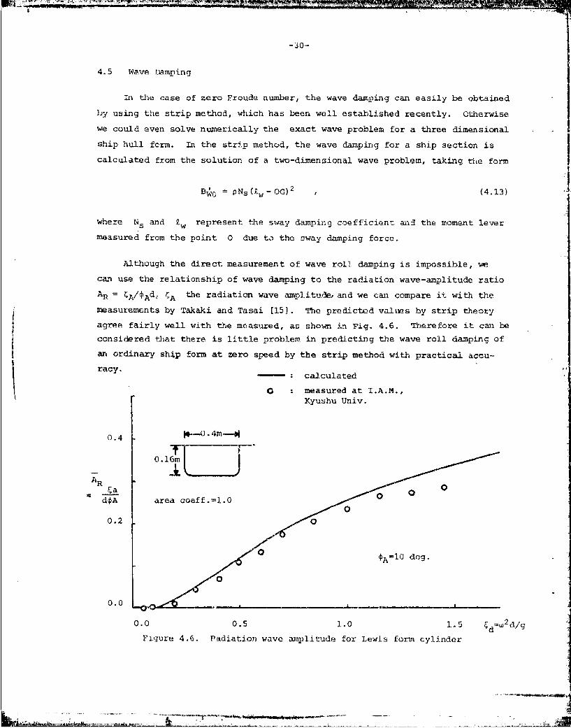
4.5 wave Damping
in the case of zero Froude number, the wave damping can easily be obtained
by using the strip method, which has been well established recently. Otherwise
we could even solve numericaJlly the exact wave problem for a three dimensional
ship hull form. In the strip method, the wave damping for a ship section is
calculated from the solution of a two-dimensional wave problem, taking the form
B pO = PNs(w-OG) 2 , (4.13)
where Ns and Z w represent the sway damping coefficient and the moment lever
measured from the point 0 due to the sway damping force.
Although the direct measurement of wave roll damping is impossible, we
can use the relationship of wave damping to the radiation wave-amplitude ratio
AR = 4A/tAdc rA the radiation wave amp].itude, and we can compare it with the
measurements by Takaki and Tasai [15). The predicted values by strip theory
agree fairly well with the measured, as shown in Fig. 4.6. Therefore it can be
considered that there is little problem in predicting the wave roll damping of
an ordinary sh p form at zero speed by the strip method with practical accu-I racy.racy.calculated
I 0 measured at I.A.M.,Kyushu Univ.
0. 4 M,-'0.4m-
0.0.
AR
dOA area coeff.=l..
0.20
AI0 deg.
0 .0 -0 ,. _ -_ ---- _ _ _ -- A l.d. .
0.0 0.5 1.0 1.5 d=w2d/g
Figure 4.6. Padiation wave amplitude for Lewis form cylinder
-31-
In the presence of ship speed, on the other hand, it is quite difficult
to treat the wave roll damping theoretically. Several approaches, for example,
Newman and Tuck 139], Joosen [403, Maruo [41], Ogilvie and Tuck 142), etc., to
improve the strip method by use of slender-body theory have recently been
attempted. Troesch [431 has evaluated the solutions of Ogilvie and Tuck's
theory for lateral ship motions. However, a definite improvement in the pre-
diction of roll damping at forward speed has not been reached, since Troesch's
result shows that the first higher-order correction to roll damping is zero
according to the slender body theory.
A method of wave-pattern analysis to obtain the radiation potential of
ship mot.ions at forward speed has recently been proposed by Ohkusu [441. It
is hoped that this methdwill make it possible to measure the roll wave damping
separately. Otherwise, we can approximate wave damping by subtracting all
other predictable components from total damping obtained in the forced-roll
test. The results show that wave damping behaves in a somewhat complicated
manner, including hump/hollow undulations.
we can cite here a couple of approximate treatments for predicting the
wave damping at forward speed. The first is the method in which the flow fieldIdue to roll motion is expressed by oscillating dipoles with horizontal lateralaxes; then roll damping is obtained approximately from the wave-energy loss in
the far field.. Hishida [ 9 1 first applied this treatment to the sway motion4
of an axisymmetric ellipsoid to obtain the characteristics of wave roll damping
at forward speed.
Ikeda et al. [371 calculated the energy loss in the far field due to a
pair of horizontal doublets and compared the results with experiments for models
of combined flat places. Through these elementary analyses they proposed an
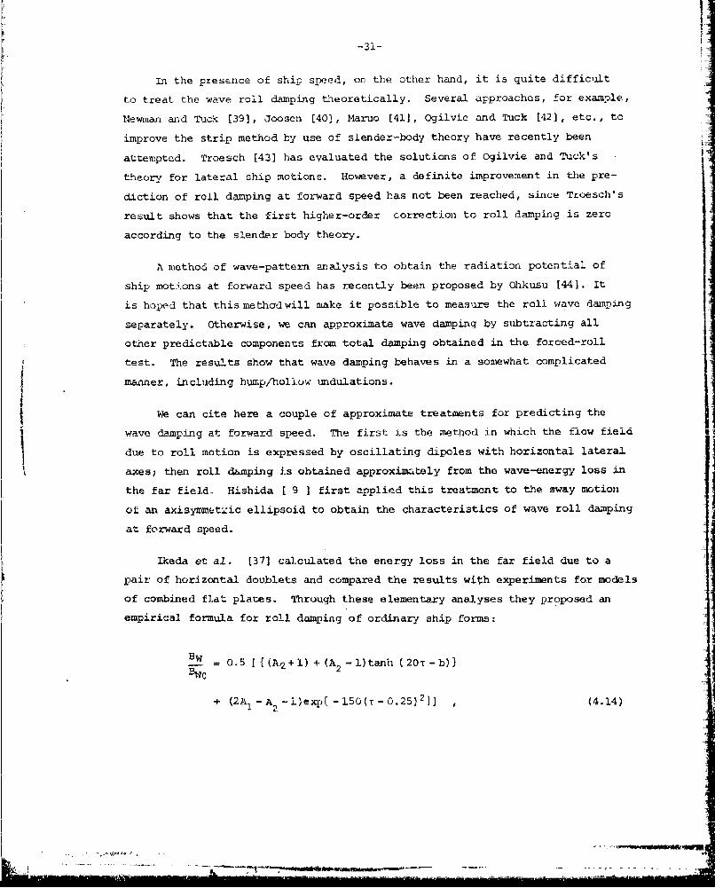
empirical. formula for roll damping of ordinary ship forms:
B W - 5 [ {(A 2 +1) + (A2 -l)tanh (20T-b)}
+ (2A1 -A2 -1)expi -150(T -0.25) 2 }] , (4.14)

r
-32-
whe re
-1.2 -2FdA 1=A1 1 I+d e
-1 -2r dA 0.5 + dd e (4.15)
Ed =2d/g T TUw/g
A comparison with experiments is shown in Fig. 4.7, in which a hump in
wave damping appears near the point T 1/4.
4 a measured at Univ. Osaka Pref.estimated
BWO Ser. 60,CB= 7 &O.719
2 BW0=0.00202
0.5 Vr.=u/Q 1.0
0.0 0.1 0.2 0.3 Fn%n
Figure 4.7. Effect of advance speed on wave component
In the second approximate method, the rolling ship hu%.l is regarded as alifting body and the wave-wake problem for this flow is solved. Hanaoka
[10] first set the equation system for the flat plate with low aspect ratio,
rolling about its longitudinal axis. Watanabe [45] has recently obtained thenumerical solution of the equation, with the result that tte roll damping is
expressed as a sum of lift and wave damping in the form
B] + B W F(Fn,TTd) (4.16)
....... = t
-33-
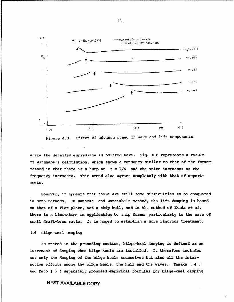
: r-Uw/g=i/4 -Hianaoka's out uncalculated by Watanabe
Be ._ = . '
.242
00.1 .2 Fn 0.3
Bigure 4.8. Effect of advance speed on wave and lift components
where the detailed expression is omitted here. Fig. 4.8 represents a result
of Watanabe's calculation, which shows a tendency similar to that of the former
method in that there is a hump at T = 1/4 and the value increases as the
frequency increases. This trend also agrees completely with that of experi-
ments.
However, it appears that there are still some difficulties to be conquered
in both methods: In Hanaoka and Watanabe's method, the lift damping is based
on that of a flat plate, not a ship hull, and in the method of Ikeda et al.
there is a limitation in application to ship forms, particularly to the case of
small draft-beam ratio. it is hoped to establish a more rigorous treatment.
4.6 Bilge-Keel Damping
As stated in the preceding section, bilge-keel damping is defined as an
increment of damping when bilge keels are installed. It therefore includes
not only the damping of the bilge keels themselves but also all the inter-
action effects among the bilge keels, the hull and the waves. Tanaka [ 4 1
and Kato [ 5 1 separately proposed empirical formulas for bilge-keel damping
BEST AVAILABLE COPY

-34-
in v Lich the effect of a variety of ship forms was partly taken into account
in terms of a modification coefticient. Cox and Lloyd [46] also obtained a
formula for the bilge-keel drag at zero ship speed using the Martin [ 3 ] and
Ridjanovic [47] experimental data. Sasajima [ 6 ] attempted to formulate
the hull pressure change due to eddy shedding from the edge of a bilge keel.
Watanabe and Inoue [11], as mentioned previously, also dealt with this problem
as an extension of Bryan's treatment. Hishida [ 9 ] discussed wave-damping
due to bilge keels in terms of a pair of dipoles on the hull with axes tangen-
tial to the hull.
It can be concluded through these works that bilge-keel damping is not
merely a quadratic nonlinear form, but that it depends on the roll amplitude.
and the frequency in a more complicated manner, and further that the effect
of ship forward speed is not so large as we might expect.
The physical meanings of these facts have been much more clarified by the
recent works of Yuasa et al. (48), Ikeda et al. [49), and Fujino et al. [50],
which are based on recent developments in research on bluff-body drag in
oscillatory motion. These works will be described in the subsequent sections.
4.7 Normal-Force Dap-ping of Bilge Keel.
To begin with, let us consider the case of zero ship speed. Much work on
the drag force on a bluff body in oscillatory motion has recently been carried
out, mainly in the ocean engineering field [51], [52), [53], [54]. It has
also been attempted to apply the results of these works to the problem of
bilge-keel drag.
Let the coefficient CD of a body be defined in the form
F = CD. p AIvIv , (4.17)
where F represents the drag force, . A the area of the body projected onto
the crossplane normal to direction of motion, and v the velocity of motion.
Although CD is assinad to be constant during the specified motion, its value
is known to vary with the period parameter or reulegan-Carpeter number, VT/0
(V is the maximum speed I vmaxl , T is the period and D the maximum pro-
jected breadth), contrary to the case of steady flow. In the case of periodic
.7

-35-
oscillatory motion, especially of bilge-keel motion, the parameter becomes
7r4A/bBX when we substitute r4Aw , i- and 2bBK for V , T and D
respectively, where r represents the mean distance from G to the bilge
keel and bBK the breadth of the bilge keel. This means that the parameter
can be regarded as a sort of amplitude ratio since it depends no longer on
the period of the oscillation.
The drag of the bilge keel can be expressed by the following formula,
which was obtained by Ikeda et al. [351 (including the case of an oscillating
flat plate), as shown in Fig. 4.9:
bBK (.8CD = 22.5 - +2.40 (4.18)
mark bBK xnumber test method model
CD 0 1.Ocm x I0- l.Ocm x 2
10 a 1.5cm x 1 free roll ellipsoid% 0 0.7cm x I
0 0.9cm x 1 press. dif. 2-dim. cy1inder
Ameasured by Ikeda et al.
5
0 _ _ _ _ _ _ _ _ _ _ _ _ _ _ _ _ _ _ _ _ _ _
0 10 Y5 VT/D 20
Figure 4.9. Drag coefficient of bilge keel
Its validity has also been confirmed by Takaki's experiment [54] except for
large amplitude, and a dependence on the amplitude ratio has appeared also
in the Cox and Lloyd formula.
However, in order to obtain the normal-force damping of the bilge keel
installed on a ship hull with comparatively small bilge radius, it is neces-
sar- to consider some modifications to Eqs. (4.17) and (4.18). Ikeda et al.
[341 assumed that the area A in Eq. (4.17) can be replaced by bBK per
-36-
unit length and the velocity should be multiplied by an empirical coefficient
f of velocity increment at the bilge circle. Then the damping takes the form
25 +.0r Aj,~~~ 2 __ f2225+ rA
+ r b2.40 (4.19)
f = 1 40.3 exp -60(l-aI , (4.20)
where a denotes the area coetficient of the ship hull section.
Fujino et al. [50] have recently assumed in a somewhat different way that
the quantity D in the definition of the period parameter should be replacedRbBK
by bI = bBK + bBK , where R is the bilge-circle radius; they include
the effect of the mirror image with respect to the bilge circle, instead of
taking D=2bK , as Ikeda et al. did. Moreover, Fujino et al. defined f as
the average velocity increment at the position of the bilge keel and they
calculated its value for several ship sections using the finite element method.
The expression for damning, however, takes a form similar to Eq. (4.19).
Considering the contribution of the amplitude 1 A in Eq. (4.19), the
first term in the bracket is independent of the amplitude, so that it becomes
apparently a linear term. This is because the effect of period parameter on
the drag coefficient occurs in the damping terms, or, in other words, the
B2 coefficient varies with amplitude so that a part of B2 is seemingly trans-
ferred into the B1 coefficient. Therefore Eq. (2.17), expressing the term-
by-term comparison between the damping and extinction coefficients, does not
hold in this case in the sense of their original definition. For the case of
a naked hull, as seen previously, the effect of period parameter is fortunately
srAll, so t!hat we can safely take B2 as a constant.
The values predicted by Eq. (4.19) for the case of a circular cylinder
with bilge keels agrees fairly well with the measured values, as shown in Fig.
4.10.
In the presence of ship forward speed, on the other hand, it is knownfrom the work of Yuasa et al. [48J that tle CD value of bilge keels
decreases slightly, as can be seen in Fig. 4.4. Instead, linear damping

-37-
appears, due to the lifting effect of bilge keels. Yuasa et al. applied the
approximation of low-aspect-ratio wings to the case of bilge keels with the
result that the normal-force damping can be expressed in the form
B = B BK r2 U (4.21)BBKN BKNO +IOB
0.008 - I formula proposed by
Ikeda et al.
B1 O : *,a: measured at I.A.M.
0.006 Kyushu Univ.
0.004
0.0
0 .0 0.5 1.0 d 1.5
Figure 4.10. Component due to normal force on bilge keel
A similar form was also adopted by Schmitke [31]. Although the decrease of
nonlinear damping is not represented in Eq. (4.21), the contribution of the
linear lifting term seems to agree with the experimental results, as shown in
Fig. 4.1, in which the ordinate Ce denotes an equivalent nonlinear drag
coefficient of bilge keel.
Recently Fujino et al. [50] have shown an impressive way of numerically
treating the drag of bilge keels at forward speed. They have assumed that the
flow around a bilge keel corresponds to the steady flow around a low-aspect-
ratio wing with breadth b I as defined before and with length equal to that
of the bilge keel. Taking the effect of the velocity increment at the bilge
circle into the expressions of the incident angle and the incoming velocity
of the wing, they have obtained the numerical solution of the bilge keel drag

-38-
De r
0a
measured by Yuasa et &I.<> aspect ratio = 0.04
0 = 0.06O =0.08
0 L0.0 0.25 0.5 1/kU/wL 0.75
Figure 4.11. Effect of advance speed on drag coefficientof bilge keel'
De 0 6 C) measured by Fujino et al.
15.0
A 0 010.0 Ic...
5.0-a =0.04 m
Samiplitude of b.k. motion
0 _ _ _ _ _ _ _ _ _ _ _ _
15.0
10.0.......
0 ..........
5.00 a 00 0 /LI
0 0.25 0 .5
Figure 4.12. Fujino's prediction for normal force 7

-39-
on the basis of Bollay's nonlinear wing theory (56]. As we can see in Fig.
4.12, the results seem to be quite promising. In the figure, the estimated
value at zero ship speed comes from their method, mentioned previously.
In conclusion, it can be noted here that the slight increase of bilge
keel drag in the high-speed range is due to the linear or nonlinear lifting
effect; the problem of the slight decrease of drag at low speed is still left Ifor future study. As a practical treatment at the present time, one might
assume that the change of bilge-keel drag with ship speed is negligible, sirce
these two effects cancel each other for ordinary dimensions of bilge keels,
as seen in Fig. 4. 11.
4.8 Hull-Pressure Damping Due to Bilge Keels IAlthough this component may be a part of the eddy damping due to the
interaction between bilge keels and ship hull, it is convenient to consider
it as an independent component for obtaining a prediction formula. According
to the works of Ikeda et al., the difference in the hull pressure with and
without bilge keels is regarded as an effect of the bilge keels. The hullpressure difference p can e defined as follows, by anlogy with CD
for the case of normal-force damping of bilge keels:
p =%. vtv . (4.22)1
Here, v represents the instantaneous relative velocity at bilge circle,
which can be assumed to be v = fr , with the coefficient f standing for
the velocity increment ratio, as stated in the previous section. It is
noted that the expression for pressure, Eq. (4.22), does not include the
term t (0 is the velocity potential), since this term seems at present
to make a small contribution to the damping in the absence of a free surface;
further study on this point may be needed.
The distribution of the pressure-difference coefficient on the
ship hull, Eq. (4.22), takes 'the shape shown in Fig. 4.13, according to the
experiments by Ikeda et al. [49] and Goda and Miyamoto [57]. The positive
pressure C+ in front of the bilge keel is not affected by the displacementp
of the bilge-keel motion, while the negative value at the rear of theC B

-.40-
bilge keel and its effective extent So around the hull depend strongly on
the value of period parameter, as does the drag coefficient of the bilge keels.
Ikeda et al. made assumptions on the shape of the p distribution and
on the values of C+ and C to establish a formula for the damping due top p
this pressure difference, as follows: 2
BB 4 T±Fpr2a2w A2 ,
(4.23)
M - 2I 0 ds
OO.25m, i=O.im, a-ea :oeft.=0.935
hBK =0.009m
--2 0 .2 C_ 0.2 0 .0 -0 .-
C C
Figure 4.13. Pressure distribution On hull induced by bilge keel
The Integration of I must be done around the whole girth, with the&integrand
C multiplied by the moment lever to about the rotation axis. The detailed
expression will be stated in the Appendix. The value of I can be determined
as a function of the hull shape and the period parameter of the motion. There-
fore it includes not only the apparent nonlinear term of 'A I similar to that
of the previous sect.ion, but also the higher-order terms of the third and
fourth powaers of *A , although their contribution is small.

.... A. " -- - . ;-
-41-
Since it is difficult to measure this component separately, the prediction
for the total bilge-keel damping without the effects of surface waves, that is,
1BK N plu; B1K H , can be compared with experiments, as shown in Fig. 4.14.
The agreement between them seems to be fairly good.
0.02
cargo snip, C,=0.71
OQA: measured at I.A.M.Kyushu Univ. j50
- : estimated by Ikeda et al.
0.01 _ I
0AA0
0
0.0 0.5 1.0 1.5
Figure 4.14. Effect of bilge keel on roll damping coefficientat zero Froude number
The research for this component in the presence of ship forward speed
does not seem to have been done. However, by analogy with the case of the
drag coefficient one may suppose the pressure difference between front and
rear surfaces of a bilge keel decreases slightly and that the width So of
its distribution on the hull also decreases slightly with forward speed.
Consequently hull-pressure damping decreases by a corresponding amount. This
amount, however, will compensate the increment of normal-force damping due to
the lifting effect, since it is known that total damping of bilge keels does
not vary much. We have just to remember here that the nature of bilge-keel
damping changes from being nonlinear to being more nearly linear as ship speed
increases.

-42- 14.9 Wave Damping of Bilge Keel
As an example of the study of this component in early times, we cite
Hishida's theoretical treatment £9]. Let the radiation waves due to the
roll motion of a bare two-dimensional cylinder be described by %Icos(koy-wt)
and the change when bilge keels are installed by CBKCOS(koy-wt+e) , where2k0 represents the wave number, 02/g , y is the horizontal axis, t the
time and e a phase lag. Then the amplitude C of the resultant wave canA
be expressed in the following form:
I
A_ H BK 2 %2A- + 42 + 2 %Kcos " (4.24) -
According to Hishida's consclusion, although the value of BK may be as
large as that of C in some cases, the magnitude of A and thus of the Idamping may not always increase with the addition of bilge keels, because of A
the difference of phase of the wave systems.
Takaki [231 has recently carried out the calculation of roll damping of
ship-l ike sections with bilge keels using the close-tit method. From the
results, as shown in Fig. 4.15, it can be said that linear theory agrees with
experiments only in case of small roll amplitude. There is still a consider- iable discrepancy for larger amplitude, probably due to the non-linear effect -
of wave damping. :]
However, it can be noted that for bilge keels with ordinary breadth of
bBK B/60 to B/80 , we can safely neglect the wave effect of bilge keels, Isince the contribution of this component is usually quite small compared to I
the viscous damping caused by bilge keels.
In the presence of ship speed, no study of this component has been made. i IFor ship forms with relatively large-sized bilge keels, like a warship, it
may be necessary to take the wave effect into consideration in cases both
with and without advance speed.
At the present tire, however, it can be concluded that the total dampiig
increment due to bilge keels can be predicted as the sum of two bilge-keel
dampings, BBKN and B..

-43-
A 0 c) measured at I.A.M. 2 20 mKyushu Univ. A, w
I* o4 -- */
/ / --
_A area coef.=1.0 / ,- ---- v-. m
// l/m
0.4
0.2
S - : calculated for bare hull
0.0
0.0 0.5 1.0 1.5 F =L 2 d/g
Figure 4.15. Radiation wave amplitude for cylinderwith bilge keels
4.10 Prediction of Total Damping
The component dampings that were introduced in the preceding sections
can be summed up to give the total damping of ship rolling. Either Eq. (4.1)
or Eq. (4.2) can be used:
Be = BF + BE + BL + BW + BBK N + BBKI + BBKW (4.1)
Be = D F .:. BE + BL + B + BBK (4.2)
Ma addition, we can add the contribution of appendages to these expressions,
as schmitke 131] has done. Although not every individual component has been
well-established for all ship forms, it is worthwhile to note that the con-
cept of dividing the damping into these components should enable us to predict
ship roll damping more accurately than by the simple methods. At present, we
can indeed choose valid prediction formulas for the component dampings; these
will be identified in the next section. Here we discuss the general properties
of the predicticn procedure and the component dampings.
- -" , .... _ --- - =-- . ..

-44-
In the absence of ship speed, since only the lift term BL becomes zero,
the other terms are predicted by integrating sectional values along the length
of the ship, as in the strip method (however, in Kato's formula, th- friction
damping for the whole ship form is still available). Therefore we can also
obtain the longitudinal distribution of the roll damping. we can compare it
with the experiments on a divided model, as performed in the Ship Research
Institute of Japan [233.
At forward speed, however, the modification to the individual components
is made for the whole ship form, not for each ship section. In this case we
cannot obtain the damping distribution, which presents an important problem
for future study.
Comparisons of these component dampings are shown schematically in Figure
4.16 with the abscissa Fn , in Fig. 4.17 with frequency w , and in Fig. 4.12
with the amplitude A * Although bilge-keel dampings are showm as nearly
constant in Fig. 4.16, the linear part increases as Fn becomes large. This
means that in Fig. 4.18 the values of bilge keel dampings in the limiting case
"'A 0 increaoc but the slopes of the corresnonding curves decrease as Fn
increases.
It can also be seen frou Fig. 4.18 that the linear dampings consist
of BL , BF , Bw and BBK W , as well as parts of BBKN and BBK H . The
nonlinear part with the constant B2 coefficient includes BE and parts of
BBK * The terms B. and B1K also depend on the frequency as shown inFig. 4.17, although they appear to be linear with respect to amplitude. This
can be realized from the facts that they were originally defined as being
nonlinear but then the coefficients varied with Reynolds namber in the case
of BF and with the period parare.ter in the case of BBK -
The scale effect on roll damping is an important problem. No detailed
experiments on actual ships have been carried out to determine the component
dampings, so that we do not yet have an exact picture. However it can be
considered as in the case of an oscillatory flat plate that dampings like
BE and B BK that are generated by separating bubbles may not be affected
by the scale difference between model and ship. The almost linear dampings
like BL and BW are of course independent of the scale effect. Therefore
only the frictional damping suffers from the scale effect. For instance,
D' L =- = " Z
4- - --. - -,. .-

-45-
BB
eB
I0.0 0.1 0.2 Fn 0.3Figure 4.16. Schematic view of roll damping components with aoivance speed 4
B
Fn,oA const.7
0.0
0.0 0.5T=.04
Figue 417. ft~t o rol frqueny 01 rl). ampng cmpoent

-46-
Fn,W constant
Be
B BKBKH
0.0 h____
BE
3wT+BBKW
BLBE,
0.0 0.1 0.2J (rad. ]jFigure 4.18. Nonlinear effect of roll damping components
when the ship roll damping is to be prediated by scaling up from the model
value, the B value for the ship can be obtained only by replacing the
BF value by that of the actual ship under the same conditions of Fn ,
and A as for the model, although BF may be neglected in t-he ship case.
Concerning the independence among component dampings, there still remain
problems. All the interaction effects have been included in proper components
by their definitions in Sec. 4.1. However, in the present prediction formulas,
the interactions are usually ignored, except for the hull-pressure change due
to bilge keels, which can be regarded as the largest '.nteraction term. 'The
other interaction effects may exist, and so they may affect the independence
of components. However, we can expect their magnitudes not to be large, since
almost all the component dampings have been determined and formulated through
corresponding experiments that already implied the interaction effects.
...•- il-- ... ....... ....r ...... .. .I ... .J... . ' I

-4--
4.11 Comparison with Experiment
Although it is still necessary to improve the prediction method for
component dampings, we can at present adopt an adequate set of prediction
formulas for component dampings for ordinary ship hull forms. The followig
is an example of the second (best) method which can be chosen in a practical
point of view.
At first we can safely use Kato and Tamiya's formula for the frictional
damping BF . Ikeda and cthers' method can be taken for B E The lift
damping BL is given by the formula of Yumuro, modified by Ikeda and others.
The wave damping can be obtained by the strip method in case of zero Froude
number and by Ikeda and others' formula at advance speed. The latter is pre-
ferred over Hanaoka and Watanabe's method, which does not yet yield an
adequate result in magnitude, in spite of the fact that it is based on a more
rigorous assumption.
For the bilge keel damping, Fujino's treatment seems to be the most
reasonable one at present time. However, since it does not include hull-
pressure damping due to bilge keels, BBK H , an alternative way is to adopt
Ikeda and others' method for predicting EBKn and BBKH at zero forward speed
and to assume that the bilge keel damping does not vary with forward speed.
F -rthermore we can neglect both the wave damping of bilge keels BBK and the
effect of the other appendages on the hull.
Using the set of formulas thus chosen, we can calculate the roll damping
of a ship once the hull form and the roll conditions like Fn , w , and 4 A
are given. A computer program for this is presented in the Appendix.
Examples of results are shown in Figs. 4.19 and 4.20 with the abscissa
Fn and in Figs. 4.21 and 4.22 with the frequency as the abscissa. We can
recognize from Figs. 4.19, 4.20 and 4.21 that the magnitude and even tie
tendency of the roll damping are predicted by this method to sufficient
practical accuracy. At the same time, however, Fig. 4.22 shows that there
still appears some discrepancy in the trend, probably of the wave damping
at forward speed. Moreover it has been reported by Ikeda et al. themselves
[37] that this method fails in cases of small draft-beam ratio or in ballast
condition, because of the difficulty of predicting the lift damping.

-48
In conclusion, it can be said that this method can safely be applied
to the case of ordinary ship hull form with single screw and rudder if the ship
is in its normally loaded condition.
0.02Ser.60, C,=0.8
0 without bilge keel
Be a with b.k ,bBK/B-o0ol95
0.0010. .
0.02
0 =0.7 rad.20.
Fiur 41. omain fmeasured adetmtdrl apn
0.02
Fiue4.0 oi apigcefiintfrcargo ship model c=.19
at forward speed

-49-
0.02
B e cargo ship , C =0.71, A. l0deg.
0 without b.k. A
with b.k.
- estimated by
0.01 Ikeda et al. ,
0 0
S0.0Q 0.5 1.0 w 1.5
Figure 4.21 Comparison between measured and estimated rollj damping coefficent at zero Froude number.
Measurements made at the Research Institute forApplied Mechanics of Kyushu University.
cargo ship model, CS=0.7119
roll axis : (OG/d-0.108)OA 0.157rad
0.01 Fn -0.2
measured 44
with B.K.C without B.K.K
0.005
estimated T
u- : sing estimated kNX0/d L
0.0-fl. O' 0.5 1.0 W
Figure 4.22 Roll damping coefficient for cargo ship modelFn -0.2
---- .. ..- L.. ..

5. TREATMENT OF NONLINEAR ROLL DAMPING IN PREDICTION OF ROLL MOTION
Since '-oll damping of a ship is quite nonlinear, as we have seen in the
preceding cnapters, special treatment is necessary in the calculation of ship A
roll response in regular or irregular seas. Although there will 7Appar other
similar nonlinearities in the restoring moment and the wave excitation, we
concern ourselves hereafter only with the nonlinearity of roll damping ..n the
analysis of roll motion.
To begin with, the roll response in regular seas can usually be obtainedfrom, solution of the simultaneous equations of ship sway, roll and yaw motions,for example, in the following linear form,
122 22 2 2 y A24 B24 C24' r6 2 2A B C y +A B C + A B CM eet ( 5 1 )L: 42444 44 62 + 46 46 C46 4
62 '62 62J c64 e64 C K E66 46 C'6 M
where y , 4 and 6 dtt 1ote the displacement in suway, roll and yaw, respec-
tively, all expressed'in complex form. In Eq. (5.1) the coefficients of wave
forces, F 2 , M4 , M6 , are expressed by an appropriate method as
functions of ship form and speed, the wave amplitude hA , encounter angle,
and encounter frequency we" The inertial coefficients in the radiation
forces, A.. (i,j=2,4,6) , can also be calculated by a similar method as
functions of we " Then we can easily solve the equations to obtain the
responses, provided that the equations are linear.
However the roll damping coefficient, B44 , is usually expressed in a
form implying dependence on the roll amplitude, 4A
B4 4 - Be(U, we A (5.2)
In this case the equation is nonlinear and must be solved by some kind of
iteration technique. Then the responses thus obtained depend on wave amplitude
hA in a nonlinear manner. This means that the nondimensional roll-response
amplitude A/khA (k: the wave number) should be stated for the hA valz.
concerned.
-50-
I yI-9 4 1- I ' -I -1 -

-51-
Takaki and Tasai [5] adopted the quadratic or cubic form,
Be = B a 8 3AB2 B3 (2.6)
to express the roll damping coefficient Be of Eq. (5.2) and they determined
the values of B 1 , B and/or B by the experiment. If we use the predic-1 2 B3
tion formulas stated above to obtain the constant values of B1 , etc., in
Eq. (2.6), however, a regression analysis with wide variations of fr-equency
and amplitude is needed, since the present prediction formulas are not always
expressed in the simple form of Eq. (2.6) but are given as a combination of
formulas for individual components in somewhat complicated manner. In order
to obtain only the roll response in regular seas, such a transfer of damping
exprcssion should not be necessary. We need only the value of the equivalent
linear damping at the specified values of ship speed, frequency and amplitude.
as in Eq. (5.2).
We now proceed to the case of irregular seas. To predict the ship response
in short-term irregular seas, the energy-spectrum analysis based on the princi-
pie of linear superposition has been applied. Let the energy spectrum of the
incoming long-crested waves be denoted by SW (). Then we -a obtain the energy
spectrum of the ship response S (C) in the form
S(W) = IA(,) 12Sw( G ) 3)
The frequency w of the waves can be transformed into the encounter frequecy
we of the ship. The response amplitude operator A(M) represents the shipresponse per wnit magnitude of input wave. In particular, it becomes A/khA
(k: the wave nustner) in the case of roll response.
The equation system is nonlinear when A(M) depends on the amplitude of
the wave and thus on the spectrum Sw(C) . Several attempts have been made to
treat this nonlinearity. The most simple way, by Fukuda et al. [29], is to take
the A(w) value as that in the case of the wave height ( 2 hA) equal to the
significant wave height, H1/ 3 . This corresponds to assuming thiat the roll
damping Be is constant, equal to the actual value associated with a roll
amplitude *A corresponding to the prescribed wave height. The w-dependence
of the roll damping, in this case, is taken into account exactly.

-52-
Yamanouchi [58] applied the regular perturbation technique to the non-
linear terms in the equation of motion. As another approach, the concept of
the equivalent linear damping, as stated in Chap. 2, has been applied to this
case:
Be B1 + 4T B2 . (2.13)
This has been derived from the assumption that the difference between linear
and nonlinear damping can, in the sense of least-squares method, be minimized
during the roll motion, which is assumed to be a Gaussian process. This
treatment also requires an iteration method of solution, in which the variance
a of the roll angular velocity is obtained in the form
0 2 2 f S(w)w2dw (5.4)
0and should be reevaluated in each iteration stage. According to Takagi and
Yamamoto's work [23], this method gives reasonable results in case of
irregular seas.
Kaplan [26] proposed that the variance be replaced by the quantity
o = n (5.5)
His justification i s that roll motion occurs largely in a narrow band near the
natural freguency wn .
It should be noted here again that the coefficients B1 and B2 are
assumed to be constant. To apply this method, therefore, it is necessarly to
rearrange formulas to obtain a regression analysis on the equivalent linear
damping in a manner similar to that stated before. For the case of a baze
hull, however, this might fail, because the roll damping is less nonlinear and
can hardly be expressed in a form like Eq. (2.6) with constant coefficients.
At the same time, this method cannot represent the w-dependence of the roll
damping so well as the first simple approach.
Dalzell [59], Hadd- . (60], and Lewison [61] have proposed expressing the
roll damping in a cubi orm without quadratic term, B 1 +B 3 0 , for con-
venience in the statistical analysis of roll motion in irregular seas.
- -C--- _ - -~- - --
6. CONCLUSION
In th.'s survey, recent trends and results of research on ship roll
damping have briefly been stated. In Chapter 2 the representation of roll
damping coefficients was sumarized and some limitations on the definitions
of the coefficients were discussed. The simple methods stated in Chapter 3
could give a rough estimation of the magnitude of roll damping at an early
stage of ship design.
Chapter 4 was concerned with the importance of the concept of component
dampings and recent works on them. Then a method of predicting the ship roll
damping of ordinary hull forms was introduced and compared with experiments,
the resulting agreement being reasonable from a practical point of view.
Chapter 5 was devoted to comments on the treatment of the nonlinearity of roll
damping in the calculation of ship roll motion.
In conclusion, it can be said that it is possible at present to estimate
ship roll damping for ordinary hull forms with reasonable accuracy. However,
there still remain problems in case of ballast condition of a ship and for
unconventional ship forms. From the hydrodynamics point of view, the linear
or nonlinear lifting force on a body in oscillatory motion and wave damping
at forward speed are still important problems.
-
REFERENCES
Note: The following abbreviations are used below:
JSNA Japan: Journal of the Society of Naval Architects of Japan
T West-Japan SNA: Transactions of the West-Japan Society of Naval Architects
J Kansai SNA: Journal of the Kansai Society of Naval Architects, Japan
1. Bryan, G.H.: "The Action of Bilge Keels," Trans. Inst. Naval Arch.,Vol. 42 (1900).
2. Gawn, R.W.L.: "Rolling Experiments with Ships and Models in Still water,"Trans. Inst. Naval Arch., Vol. 82 (1940).
3. Martin, M.: "Roll Damping Due to Bilge Keels," Report, Iowa University,Institute of Hydraulic Research (1958).
4. Tanaka, N.. "A Study on the Bilge Keel," Part 1 to 4, JSNA Japan, Vols.
101,103,105, and 109 (1957, 1958, 1959, and 1961).
5. xato, H.: "Effects of Bilge Keels on the Rolling of Ships," JSNA~Vol. 117 (1965) (in Japanese) .
6. Sasajima, H.: "On the Action of Bilge Keels in Ship Rolling," JSNA Japan,Vol. 86 (1954) (in Japanese).
8. Ueno, K.: "Influence of the Surface Tension of the Surrounding WaterUpon the Free Rolling of Model Ships," Report, Research Inst. for Applied
Mech., Kyuishu Univ. (1949).
9. Hishida, T.: "Study on the Wave Making Resistance for the Rolling ofShips," Parts 1 to 6, JSNA Japan, Vols. 85, 86, and 87 (1952, 1954, and1955) (in Japanese).
10. Hanaoka, T.: "Non-Uniform Theory of Wave Making on Low-Aspect-RatioLifting Surface," 1Gth Japan Congress for Applied Mechanics (1960) (inJapanese). I
11. Watanabe, Y. and Inoue, S.: "Calculation Method for N Value of ShipRolling," T West-Japan S!A, Vol. 14 (1957) (in Japanese).
12. Yaminouchi, Y. : "Analysis of Ship Responses in Waves," Part 1, JSNAJapan, Vol. 109 (1961) (in Japanese).
13. Vugts, J.H.: "The Hydrodynamic Forces and Ship Motions in Waves," Ph.D.Dissertation, Techn. Univ., Delft (1970).
14. Fujii, H., and Takahashi, T.: "Measurement of the Derivatives of Sway,Yaw and Roll Motions by Forced Oscillation Techniques," JSNA Japan,Vol. 130 (1971) (in Japanese).
-54-
- -!

-55-
15. Takaki, M., and Tasai, F.: "On the Hydrodynamic Derivative Coefficientsof the Equations for Lateral Motions of Ships," T West-Japan SNA, Vol. 46(1973) (in Japanese).
16. Takezawa, S., Kojima, R., and Takekawa, M.: "New Forced OscillationMethod Using Water Waves as Exciting Forces," JSNA Japan, Vol. 136 (1975)(in Japanese).
17. Bolton, W.E.: "The Effect of Bilge-Keel Size on Roll Reduction,"Admiralty Experiment Works, Rep. 19/72 (1972).
18. Lofft, R.F.: "RFA Engadine: Effect of Bilge Keels on Rollinq and Motionin Head Seas," Admiralty Experiment Works, Rep. 16/17 (1973).
19. Lugovski, V.V. and others: "Experimental Study of Scale Effects onEvaluation of Roll Damping Action of Bilge Keels," Contributed Paper,Seakeeping Committee Rep., 14th ITTC, Ottawa (1975).
20. Gersten, A.: "Roll Damping of Circular Cylinder with and withoutAppendages," Naval Ship R & D Center, Rep. 2621 (1969).
21. Takaishi, T., Yoshino, T., Takagi, M., and Saito, K.: "On the Motions ofa High-Speed Container Ship with a Single Screw in Oblique Waves," JSNAJapan, Vol. 129 (1971) (in Japanese).
22. Tanaka, N., Himeno, Y., Ogura, M., and Masuyama, K.: "Free Rolling Testat Forward Speed," J Kansai SNA, Vol. 146 (1972) (in Japanese).
23. Japan Shipbuilding Research Association, Reports of Committees SR 108,SR 125, SR 131, and SR 161 (1970 to 1979) (in Japanese).
24. Tasai, F.: "Equation of Ship Roll Motion," Res. Inst. for Appl. Mech.,Kyushu Univ., Rep. No. 25 (1965) (in Japanese).
25. Motora, S.: Theory of Ship Motion, Kyoritsu Shuppan Book Co. (1964)(in Japanese).
26. Kaplan, P.: "Nonlinear Theory bf Ship Roll Motion in a Random Seaway,"Webb Inst. of Naval Arch., Lec. Notes (1966).
27. Vassilopoulos, L.: "Ship Rolling at Zero Speed in Random Beam Seas withNonlinear Damping and Restoration," Jour. Ship Research (1971).
28. Watanabe, Y., Inoue, S., and Murahashi, T.: "The Modification of RollingResistance for Full Ships," T West-Japan SNA, Vol. 27, (1964) (inJapanese).
29. Fukuda, J., Nagaftoto, R., Konuma, M., and Takahashi, M.: "TheoreticalCalculations on the Motions, Hull Surface Pressures and TransverseStrength of a Ship in Waves," JSNA Japan, Vol. 129 (1971) (in Japanese).
30. Takaki, M.: "Ship Motion in Shallow Water," T West-Japan SNA, Vol. 50(1975) (in Japanese).

-56-
31. Schmitke, R.T.: "Ship Sway, Roll, and Yaw Motions in Oblique Seas,"Trans. Soc. of Naval Arch. and Mar. Eng., Vol. 86 (1978).
32. Myrhaug, D., and Sand, 1.0.: "On the Frictional Damping to the Rollingof a Circular Cylinder," Inst. for Skioshydrodynamikk, Norges TekniskeHogskole, Trondheim (1978).
33. Ikeda, Y., Fujiwara, T., Himeno, Y., and Tanaka, N.: "Velocity FieldAround Ship Hull in Roll Motion," J. Kanse.i SNA, Vol. 171 (1978) (inJapanese).
34. Tamiya, M., and Komura, T.: "Topics on Ship Rolling Characteristics withAdvance Speed," JSNA Japan, Vol 132 (1972) (in Japanese).
35. Ikeda, Y., Himeno, Y., and Tanaka, N.: "Ship Roll Damping - FrictionalComponent and Normal Pressure on Bilge Keel," J Kansai SNA, Vol. 161(1976) (in Japanese).
36. Ikeda, Y., Himeno, Y., and Tanaka, N.: "On Eddy Making Component of RollDamping Force on Naked Hull," JSNA Japan, Vol. 142 (1977) (in Japanese).
37. Ikeda, Y., Himeno, Y., and Tanaka, N.: "Components of Roll Damping ofShip at Forward Speed," JSNA Japan, V'-i. 143 (1978) (in Japanese).
38. Yumuro, A.: "Research on Anti-Rolling Fin," Part 2, I.H.I. Tech. Rep.,Vol. 10, No. 2 (1970) (in Japanese).
39. Newman, J.N., and Tuck, E.O.: "Current Progress in the Slender BodyTheory for Ship Motions," 5th Symp. on Naval Hydrodynamics, Office ofNaval Research, Wasbbngton D.C. (1964).
40. Joosen, W.P.A.: "Slender Body Theory for an Oscillating Ship at ForwardZ-eed," 5th Symp. on Naval Hydrodynamics, Office of Naval Research,Washington D.C. (1964).
41. Maruo, H.: "An Improvement of the Slender Body Theory for OscillatingShips with Zero Forward Speed," Bulletin, Faculty of Eng., YokohamaNati(anal Univ., Vol. 19 (1970).
42. Ogilvie, T.F., and Tuck, E.O.: "A Rational Strip Theory of Ship Motions,"Rep. No. 013, Dept. Naval Arch. and Mar. Eng., Univ. of Michigan (1969).
43. Troesch, A.W.: "Forward Speed Effects on the Sway, Roll, and Yaw MotionCoefficients," Rep. No. 208, Dept. Naval Arch. and Mar. Eng., Univ. ofMichigan (1978).
44. Ohkusu, M.: "Analysis of Waves Generated by a Ship Oscillating andRunning on a Calm Water with Forward Velocity," JSNA Japan, Vol. 142,(1977).
45. Watanabe, I.: "On the Effect of the Forward Velocity on the Roll DampingMoment," Papers, Shiup Res. Inst. Japan, No. 51 (1977).

-57-
46. Cox, G.G., and Lloyd, A.R.: "Hydrodynamic Design Basis for Navy ShinRoll Motion Stabilization," Trans. Soc. of Naval Arch. and Mar. Eng,Vol. 85 (1977).
47. Ridjamovic, M.: "Drag Coefficients of Flat Plates Oscillating Normallyto Their Planes," Schiffstechnik, Vol. 9 (1962).
48. Yuasa, K., Fujino, M., and Motora, S.: "New Approach to HydrodynamicForces on Oscillating Low Aspect Ratio Wings," JSNA Japan, Vol. 144(1979) (in Japanese).
49. Ikeda, Y., Komatsu, K., Himeno, Y., and Tanaka, N.: "On Roll DampingForce - Effects of Hull Surface Pressure Created by Bilge Keels,"J Kansai SNA, Vol. 165 (1977) (in Japanese).
50. Fujino, M., Ida, T., Maeto, T., and Numata, T.: "A Consideration on theHydrodynamic Normal Forces Acting on the Bilge Keel," JSNA Japan, Vol.144 (1979) (in Japanese).
51. Keulegan, G.H., and Carpenter, L.H.: "Forces on Cylinders and Platesin an Oscillating Fluid," Jour. Res. Nat. Rr. Standards, Vol. 60(1958).
52. Sarpkaya, T., and Tuter, 0.: "Periodic Flow about Bluff Bodies," Part 1,Naval Postgraduate School, Rep. No. NPS-59, SL74091 (1974).
53. Paape, A., and Breunere, H.N.C.: "The Influence of Pile Dimension onForces Exerted by Waves," Proc. 10th Conf. Coastal Eng., American Soc.Civil Eng., Vol. 2 (1969).
54. Shih, C.C., and Buchanan, H.J.: "The Drag on Oscillating Flat Plates inLiquids at Low Reynolds Numbers," Jour. Fluid Mech., Vol. 48, Part 2(1971).
55. Takaki, M.: "Ship Motions in Shallow Water," T West-Japan SNA, Vol. 52(1976) (in Japanese).
56. Bollay, W.: "A Nonlinear Wing Theory and its Application to RectangularWings of Small Aspect Ratio," Zeit. angew. Math. Mech. (1939).
57. Goda, K., and Miyamoto, T.: "Measurement of Pressures on Hull and Deckof Two-Dimensional Model in Large Amplitude of Oscillation," T West-JapanSNA, Vol. 49 (1975) (in Japanese).
58. Yamanouchi, Y.: "An Application of Multi-Spectrum Analysis to ShipResponses and Treatment of Nonlinear Response," JSNA Japan, Vol. 125(1969).
59. Dalzell, J.F.: "A Note on the Form of Ship Roll Damping," Jour. ShipResearch, Vol. 22 (1978).
-58-
60. Haddra, M.R.: "On Nonlinear Rolling of Ships in Random Seas," Internat.Shipbuildin; Progress, Vo.l. 20 (1973).
61. Lewison, G.R.G.: "Optimum Design of Passive Roll Stabilizer Tanks,"The Naval Architect (1976).
Ij
t
- r--..

............ --- ________________i
APPENDIX: An Example of Computer Program on Ship Roll Damping
This appendix provides the detailed expressions that have been omitted inthe previous chapters. Then a computer program of the proposed method stated
in Section 4.11 will be shown as an example. II
The friction damping BF according to the Kato-Tamiya method can be2written in the form *1:1
BF0 = BF (1+4.1U/wL) , (Al)
Bo = S-P S r~wCf ' ()
3.222 1/2
Cf =1.328 [ 2w J '(A)
and S and rs are defined in Eqs. (4.4) and (4.5). A
For the eddy damping at zero ship speed, the Ikeda et al. formula can be 4expressed in the followdng yom,
4od A
Bk 3 ,
where zt)CP 0.5 87 exp (-0y)4 exp (-0.187y) + I
S .5l + tanh.
= 0.5 [ COS7j -1.5 CXPp-'5(1-a)i sin 2 , (A6
and the velocity-increment ratio y can be expressed:
r + (A7)2d 1-- r' rH o
-d9 J

-60-
with
B H CI - O_ !,"
2(1+a, +a 3 ) , 1 OG/d 1-0G/d
H = 1 + a2 + 9a2 + 2a (1 - 3a )cos21p - 6acos 41P,1 3 1 33A = -2a3cos 51 +al(I-a 3 )cos 3t +{ f6-3a,)a3 + (a2-3a)a 3 + a
2}cos,11 (M8)B = -2a3 sin 5 +a i (1- a3 )sin 3q +{ (6 + 3a )a2 + (3a1 +a2)a 2 +a2Isin*,
rma x =MF_ (i +a,)sin - a 3sin 3}2 +{(i-a )cosVh + a3cos 30}gl/2
(wher, r ma( ,ji rmax1)
=a (1 s- a~ + a 3 ) (A9)
-oS. 4a ='2 (when r max( I ) < r mx(*2)),
f 3 =1+4 exp {-1.65xlO05 (l-) 2 }. (AIQ)
The forward-speed effect is stated in Eq. (4.8).
The lift damping is given in Eqs. (4.11) and (4.12).
The wave damping at zero speed should be predicted by the strip method;
the computer program presented here does not include this term. The modifi-
cation of wave damping to account for forward speed is stated in Eqs. (4.14)
and (4.15).
For the bilge-keel damping B , only the terms BBKN and BBKH are
used here; we neglect the wave effect B BKW The assumption is made that
BBK is constant with ship speed. The expression of BBKN is given in Eqs.
(4.19) and (4.20). BBKH can be expressed:
B = 4 P r2 d4 , I.f 2 (All)

-61--
where
I = Cptods ~A + Bp (A12)
the coefficient f is given in Eq. (4.20), and
+=1.2b(~)
+ 2K -51. 2= %-% .CrDrf 6A
Further,
A= (m3 +m4 )m -m 2
m3 (l-Mi) 2 (2m 3 -m 2 )
--3(H0 -0.25mi 6 (l-0.215mi) .m1 (V'3rm5 +m4n 6 )
m7=R/d, m2 =OG/d, m3 =l-mI-m 2 ,im 4 =n 0 -m I , (A4)
0. 414Ho + o.o65 Im - (0. 382 0 + 0. O1OG) m
(H0 - 0.215mI) (1 - 0.215m)
0.414HO +0.0651im- (0.382 +0.0106H)mlm6 = (HO - 0.215ml ) (1 - 0.215mi)
S0/d - 0.25nrm1 (S 0 > 0,25ilk) ,m=
0 (So < 0.25rR) ,
M7 + 0.414m, (SO >2S.25rR) ,1r8 r7 + Y'2 {1cs0/ m ( O _0.25TrR),.
The bilge-circle radius R and the distance r from the roll axis to the 'A
bilge keel are given in the form
2d (R<d, R<8/2)
R d (H0 l, P/d>l) (AI5)
BI

-62-
21/2G 2 R(A16)
0j T2 dd 2 )d
A computer program can be written in the following form:
(1) INPUT
1) Title (70 words) In put type 70A12) L,B,D,NABLA,CB,CM 6F10.0
L ; length b ; breadth D ; draft (m)NABLA ; displacement volume (m 3 )CE ; block coeff. CM ; midship coeff.
3) NUE F10.0NUIE kinematic viscosity (m3/s)Empirical formula
v=0.0178/(l0.0336t+0.000221t 2 ) cm2/st ; temperature (0 C)
4) M,N 21 5M ; the number of calculation points of Fn (interval:
Fn=0.02)N ; the nu.tber of input data of sections
(= the number of data cards of 5)5) X(I),H0(I),SG(I),BX(I),DX(I) 5F10.0
X(I) ; the number of S.S (0.0 at A.P.&l0.0 at F.P.)H0(I) ; half breadth/draft (=BX(1)/DX(I)~SIG () area coefficient (=cross section area/BX(I)DX (1)
BX(I) ; breadth m)
DX(I) ; draft (i)6) BBKXBKIrSBK,2 3Fi0.0
BBK ; breadth of bilge keel (m)XBKI ; SS number of aft end of bilie keelXBK2 ; SS number of fore end of bilge keel
7) OGD,T,THETA 3F10.0CGD ; =OG/d
T ; roll period (sec)TIETA ; roll amplitude (rad)
8) BWOSM F10.0EWOSM ; BW at Fn'0.0 calculated by potential theory
(2) OUTPUT
1) prints of input data2) distribution of the coefficient CR of the eddy making component.
(CR7Mp/(0.5pd 4 4jj , MPE ; roll moment due to the eddy makingcomponent)
3) distributions of ABBK and ABN/ABBK.ABBK ;BBK for unit lengthAAN ;Bjq for unit length
4) each component BFIWIB, BL, BBK 1fates of each component for each Fntotal roll damping coefficient t44

-63-
Flow chart of the program
READ TITLE
READ LR,D,NAI3LA,CB,CM
READ NUE
READ M,N
FRAD X() ,HO(I),SIG(I) ,X(I),D-X(I)- I~. N
REN _BXK1XKk.SUB~~~~ RRCIN U A SUB LTETA SBED
SFRICTION DAM. BO WAVE AKIN LIFT SUBFO EDD AINUDBP BKP
FOR EACH FN. DAMP. FOR EACH EACH FN. FOR EACH FN. ASSUMED CONST.
FN. AT ADVANCE SPEED
The program is written in FORTRAN IV, as follows.
-- ----- V____________________________ % -ow-

-64-
<PAGE 1> --------------
I DATE:09-25-SI,1416:- - -- - -- - - - a
IC *****ESTIMATION OF ROLL DAMPING**'2 CCOOED BY Y.IKEDEA.3 REAL L.NUE.NABLA4 DIMENSION X(25) .H0(25) .SIG(25) ,BX(25) ,Dx(25) .B44HAT( ioo),5 BWHAT(100),BEHAT(100),BLHAT(ioO)G * FN(10O),TITLE(7O).BFHAT(1O0)7 READ (5,100) (TITLE(I),Iu1.70)8 100 FORMAT (7loAD9 C 0*PRINCIPAL D:MENSIONS*-* L-LENGTH,B-BREAOTH.OSOPAFT,NABLA-VOLUM10 C **CS-BLOCK "OEFF.,CM-MID)SHIP COEFF.,1i READ (5,101) L,8.D.NABLA.CB,CM12 101 FORMAT (GFIO.O)13 READ (5,103) NUE14 103 FORMAT (F10.0)15 c NUMBERS OF FN AND DATAS *
16 READ ( 5. 104 ) PA.,N17 104 FORMAT (215)18 C * PARAMETERS OF EACH SECTION *** HO-B/2O.SIG-S/BOBX-BREADTH19 C OX-DRAFT21 1 READ (5,105) X(I),HO(I),SIG(I),8X(I),OX(I)22 105 FORMAT (5F10.0)23 C s' BILGE KEELS DATA ** 5.5K-BREAD)TH OF 6.K..XBXI-X OF B.K. END24 C XOK2wX OF B.K. END(FOR)25 READ (5,106) BBK.XBKI,XB3K226 106 FORMAT (3F1O.0)27 S CONTINUE2B C *** CONDITION *00 OGO-OG/0,T-PERIDD,THETA-AMP. OF ROLL29 READ (5,102) OGD,T,THETA30 102 FORMAT (3F10.0)31 IF (T.LT.0.000001) STOP32 C " WAVE MAKING COMPONENT AT FKNO-3RA(5 0)SWS-34 WRITE (6.200) (TITLE(I),I-1.7O) 335 200 FORMAT (lI1.///,X.SH'**""*,2X.7A.2X.H***) 5Y36 WRITE (6.300) L.B,D.NABLA.CB,CM37 300 FORMAT (OH .//,5X.BHOATA**,2X,2HL-,FB,5,2X,2Hs-.F.,2X,2D-o35 * FS.5,2X,GHNABLA-.F8.5,2X.3HCBs.FB.5,2X,3HCM-,FB .5)39 WRITE (6,301) OOD,T,T'HETA.NUE.BWOS;M40 301 FORMAT (IN .SX,5HOG/D-,FB,3,2X.2 Tt.FS,.2X,GHTHETA-.FB,3,3MRAD41 * 2X,41INUE-.F12.8,2t6.HP.WOSMP..Fib.iO)42 WRITE (6,302) UBK.XB'Ai;XBK243 302 FORMAT (iH .5X,4HB8K-,FB.6,2X.SHXBKlPFB.3,2X,5HXBK2-,PB,3)44 WRITE (6,304)45 304 FORMAT (IN .//,4X,25N"'DATAS OF EACH SECTION")46 DO 15 1I-1.,N47 IS WRITE (6.303) X(I).HO(I),SIG(I).UX(I),DX(I)48 303 FORMAT(IH ,4X,3HSSO.FS.3,3x.3HHD-.FS.5.3X.6HSIGMA-,F8.5.3X.2HBN49 * F8.5.3X.2D-.F8.5)so C5I OMEGAE6.20318/T52 DO 2 Iin1.M53 2 FN(I)"0.0+0.O2*FLOAT(I-l)54 CALL FRICT (LB.D.CB.NABLA.OGDNUE .OMEGA ,FN,BFHAT*M)65 *CALL WAVE (L,D.OMEGABWOSlMFN.EWHAT,M)56 CALL LIFT (L.5.DCMNABLA.OGDFN.BLHAT,M)57 CALL EDDY (X,H-i,SG.Rx ,OX.8,D.NABLA.OGOOMEGA,THETA.FN,58 *BEHAT.M.N.L)
<PAGE 1> 11 FILE:-A >>>:Pnf> MAIN PROGRAMcc

<PAGE 2> - -- --------------- - --
D ATE:O9-25-8l.14:16:-------------
69 IF (SB.LT.o.c00oooooool) GO Ta 2060 CALL UK (X,HO. SIG,8X.DX,8.O.NABLA.OGO,OMEGA.THETA,UBK,61 *XBK1.X8K2,LIBKHAT.M.N,L)
G2 20 IF (UUK.LT.O.OOOOOOOOOI) BBKHAT-0.O63 DO 3 Iul.M64 3 B44HAT(I)'BFHAT(I)+BWHAT(I)+BLHATtI)+BEIAAT(I)+SBKHAT65 c66 WRITE (6.201)67 201 FORMAT ( IH .///,4X.2HFN,6X,SHBFHAT.SX.SHUWHAT.5X.SHBEHAT,5X.68 S HBLH-AT,5XGHBKH-A,4,2H'%,3X,6HBF/844,4X.6M8W/844.69 *4X.6HRE/844.4X.6I-4L/S44.2X,7RBBK/R44.4X,2H*.2X.
70 *6HB44HAT.2X.2H**)
71 00 4 1-l,M472 BFF-BFHAT(I)/844HAT(I)73 8WW-BWHAT(I )/B44HAT(I)74 SEE-BEHAT(I)/a44HAT(I)75 BLL-BLHAT(I)/B4AHAT(I)76 BKBD6KHAT /OA4HAT(I)77 4 WRITE(6,202)FN~L),BF-AT(I ).8w1iAT().BEHAT(I).BLMAT(I).BEKHAT,
78 BFF.SWW.UEE.SLL.BEKK.B44HAT(I)79 202 FORMAT (IH *2X,F6.3,2X,FS.S,2X.FS.S,2X,FS.5,2X,FS.5,2X.FS.5s0 * JX,2H**.2X,F8.5.2X,FB8.5,2X,F8 .5,2XF8.5.2XFB8.5,2X,81 *2H**.IX.F8.5.1X,2H*Ol
82 GO TO 5833 END
EPAGE 21p11 FILE;-A //i')>MAIN PROGRAMCc4

-66-
<PAGE 3: --------------
I QATE:O9-25-81.14:16 1
8485 SUBROUTINE LIFT (L,B.D),CM.NABLA,OGD.FN,BLHAT.M)SG C LIFT COMPONENT87 C REF. V.IKEDA El AL (JZK.NO.143)as REAL LNABLA,KAPA,KN,LO,LR89 DIMENSION FN(IOOLBLHAT(100)s0 IF (CM.LE.0.92) KAPAaO 0S1 IF (CP4LE.0.97.ANO.CM.GT.0.92) KAPA"Q.i92 IF (CM.GT.0.97) KAPA"0.393 KN-6.28319'O/L+KAPA'(4.1'83/L-0.045)94 0G-G6*D95 LOtO.3O096 LRtO.5*O97 DO 1 I*1.m98 1 ELH~AT()L*DKN*LOLRtFN(I)*0.5/(NABLA*BS*2)WSQRT(0.5*tAB)*(1.0-99 *1.4*CG/LR+0.7*OG**2/(LO*LR))
100 RETURN101 END
(PAGE 3> //IFILE;-A 11/ SUBROUTINE LIFT t<

-67-1
<PAGE 4> +---------------IDATE:09-2!-81,14:i6!-- -- - -- -- -
102103 SUBROUTINE WAVE (L.D,OMCGA.BWOSM.FN.BWHAT.M)104 tWAVE MAKING COMPONENT1os c REF V.IKEDA ET AL. (dJZK.NO.243)106 REAL L, LOMEGA107 DIMENSION FN(100),BWHAT(100)108 GUZAIDOMEGA**2*D/9.8061C5log Alul .04GUZAID(1.2VErXP(-2O*GUZAID)110 A2sO,5i+GUZAIDY 1-.OP*EXP(-2.*GUZAID)
111 ~00 11,
112 LOMEGA-OMEGA*FN(I)*SORT(L/9.80666)
113 1 BWHAT(I)BWoS-M*0.(((A210)+(A21.0)*TANN(20O0(LOMEOA-O.3)))4114 *(2.0A1-A21.Oh*EXPV-1S0.0*L0MEGA0.26)t*2))
115 RETURN116 END
IA
-KPAE 0 ILE-A SBROTINEWAh

-66-J
<PAGE 5> ---------------
I ATE:O0g-25-481.14:16:- - - - -- - - ------
117118 SUBROUTINE FRICT (L.8.D.CB.NABLA,OCD,NUE,OMEGA,FNIBFHAT,M)1 19 C FRICTIONAL COMP'ONENT120 C REF. 1-IKATO (Jk(.NO, 102) AND S.TAMIYA ET AL. IJZK.NO.132)121 REAL NABLA.NUE,L122 DIMENSION FN(100).BFHAT(l0O)123 'SFlLII7*O4Cf39)124 RFa((O.687+0.145*C6)*(1.7*D+CO*8)-2.0*OGD*D))/3.145125 00 1 I-I.M126 1 BFHAT(li)-o.7a*sFsRF..2.SORr(OMEGA.4uE*6/ 19 ,6132)/(NABLAe8.12)127 4*(1.044,l'FN(I)/OMEGA'SQRT(9.80665/L))
128 RETURN129 END
1AI A
(PAGE 5> // FILE:-A /// SUBROUTINE FRICT

-69-
<PAGE 6> --------------DATE:09-25-8I. 14:16:
130131 SUBROUTINE EDDY (XHO.SIG,BX.0X ,B,D,NABLA.OGD.OMEGA.I-IETA.FN,132 1 BEHA T, M.N, L133 C EDDY MAKING COMPONENT134 C REF. V,IKEDA ET AL (JZH.NO.142,UZK.NO.143)135 REAL NABLA.LTHETA.L
136 DIMENSION X(25) ,HO(25),S,-IG(25).BX(25).DX(25).FN(l100)*BEHAT( 1003.137 *RMAXI(2),V(2),CR(25),CRI(25) .Xi(ao)138 00 1 J-I,N
139 ARO.NO(,J)/ I.0-OGD)t140 SIGMA-(SIGGJ)-OGOJ/(I.0-OGD)IA I EI(AHO-1I.0)/(AH0O .0)142 E2E2 It143 As4.0'SIGMA,(1.0-E2)/3,1415+E2I144 Cw-A/(A+3.0)145 C2.SORT(0*42-(.-l .0)/(A+3.0))146 A3'0Q-02147 AIWES(1.0O+A3)148 AMD8X(J)/t I 0-eA+A3)'0.E149 AAI.AI*(1.04-A3)/A3*0.25ISO IF(AAi.GT.1,0) AA1-1 .0151 IF(AAI.LT.-l.O) WA-1.0152 00 2 1-1,2153 LTHETA-0.5*ARCCS(AA1)
154 IF (l.EQl) LTHETA-O.O155 AHmI,04+A**2+9.OA3**2+20A*(1.03.0A3)*C0S(2.0*LTHETA)-6.&*A3156 *CDS(4O0*LTHETA)157 AA"-2.0*A3'COS(5.0viLTHETA).A1'( I.0-A3)*COS(3.O*LTHETA)+((6.0-3.0*
159 Al )*A3**2+(Al**2-3.O*A1 )*A3+AI**2)*COS(LTHETA)159 *BB.-2.0*A3'sIN(5.0*LTHETA).Ai*(i.O-A3)*S1N(3.O*LTHETA)+((6.0+3.O*
122 RMAA1(I)AM*5RT 1.0+A)SI(LTHFTA)A3SI!N(3.0*LTHETA))*02
I6 e* +((tO0-Aj)*COS(LTHETA)s.A3*CD5(3O;9LTNETA))**2)164 RMAX-RMAXI(l)iG 15VMAX-V( I)160 IF (RMAXI(1.LE.RMAXI(2)) GO 10 8167 GO TO 9168 8 RMAXrRMAXI(2)169 VMAX-V(2)170 9 CONTINUE171 RMEANU2.0&DX(1 3)*(l.0OO)*SQRT(AHO*SIGMA/3. 1415)172 Pl.VMAX/RMEAN173 P2-RMAX/RMEAN174 PP3'Pi+P2175 IF (SIGMA.LT.0.99) GOTO 20176 GAMMAu(1.0+4.O*EXP(16500.O*(.O-SIGMA)02))PP31717 6070 21178 20 GAMMAwPP3179 21 CPWO.5*(0.87*EXP(-GAMMAh-4.O*EXP(-0. 187*GAMMA)+3.O)180 Ft-o.5'( l.04TAM-(20.0'(SIG(JVO0.7)))
182 4. SIN(3.1415'SIG(J)2183 Rv2.O*OX(,J)*5ORT(HO(tJJ*(StG(fl-l.0)/(-Q.8584))184 RD'-R/DXUJ)Ias IF (HOl(d).LE.1.0.ANO.lRD.GE.AHD) PuO.5*BX(J)186 If (HO(J).GT.i.0.AND,RO.GE.1.Q) R0OX(d)187 RDwR/OX (J)
<PAGE 6~//IFIL'..:-A /11 f>SU8RourINE EDDY

-70-
'cPAGE 7> 4- - - - - - - - --I OATE:O9-25-81,14:16:
188 i CR I (,J).MAX*2/DX',()2*CP*((I.0-F1 RD)'*( I.0-OGDF 1RD)4F2*189 *(HO(4)-FiiP.Oh'2)
190 WRITE (6.452)191 452 FORMAT (1H ,//,4X,4H****,31HLONGlTUOlNAL DISTRIBUTION OF CR,192 *411***.
193 DO 10 Q-I, N194 10 WRITE (6.453) x(j),CRi(J)195 453 FORMAT (UiH .4X.3HSS.FS.5,4X.3ICPA,FO.5)196 DO 3 K-1.21197 X1(K)wO.0+O.5*FLOAT(K1-)198 MAX-N199 3 CALL HOKANI (XCR1. 25.MAX,X1(K),CR(K),DAM,1.0)200 CR( 1 1.51( 1,0-aGO)201 CR(21)rI.S*(A.0-0GD)202 SAM-0.0203 00 4 K-110204 K2-2 t K205 Ki-K2-120G K3-K2+l201 SAMI'CR(KI )+4.0'CR'(R2)+CR(KO)208 4 SAM-SAM'SAMi209 CRTrSAM/6O.0210 BEHAT(I)s4.Q*L*O)*4/3.0/3,14l5*'OMEGA*SQRT(8/1986)/NAELA/6''2'CRT,211 v THETA212 DO 5 1-2,M213 AK-OMEGA/FNLIPlSQRT(L/9.8)
214 5 6EHAT(T)-BEHT(I)(0.4AK)**2/UO0.04*AK)*2+1.0)I215 RETURN21G END
(PAGE 7? I/I FIL!:-A I// n)SUBROUTINE EDDY d

<PAGE 8> --------------
I PAIL:09-2581. 14: 15S-
217 .. **..218 SUBROUTINE BK (X,HC,SIG,BXDX ,8.D.NABLA,OGDUMEGA.THETA .88K,219 *XBKI.X8K2.BKHAT,M,N,L)"20 C DAMPING DUE TO BILGE REELS.221 C REF. YIREDA ET AL (KZR.NO.1G1, KZR.NO. 165)222 REAL NABLA. MI.M2.M3,M4,M5,MGM7,M8,L223 DIMENSION X(25) .HO(25),SIG(25),BX(25),DX(25),BBKHAT(25).XBK(25)224 ,RATIU(25)225 XBK(l)-XBKI226 XBK(11).X6K2227 00 1 1-2,10228 1 XBK(I)=XBK(I-1)+(XB3K2-XBSKI)0O.122.9 MAX-N230 DO 2 1-1,11231 CALL HOKANI (X,HO. 25.MAXX8X(I).HOI,DAM.l.0)232 CALL HOIKANI (X,S[G, 25.MAX,XBK(I).SIGI.DAMI.1.D)233 CALL HOKANI (X,DX, 25,MAX,XBK(ILDXI.DAM.1.O)234 CALL HOIKANI tX,BX. 25.MAX.XBK(I),8Xl,DAM.I,o)235 R-2.04OXl'SQRT(HOI*(SIG1-1 .O)/(-o.BSBS))236 RD-R/DXi237 IF (HCI.LE.I.o.AND.Ro.GE.HOI) R-0.SGEXI23S IF (HOI.GT.I.O.AND.RD.GE.1.0) R-DXI239 RD-R/DXI240 Fnl.040.3DEXP(-160.0*(1.0-SlIG))241 RBK-DXPISORT((HOl-O.2S29tRD)**2+(l.0-CGD-0.292S*RD)*12)242 MI-RD243 M2-OGO244 M3=i.0-M--M2245 M4,HOl-M1246 MSn(O.4I4*HD1+0.065ItMfl2-(0.3B2*HCl+0.01O6)vM1 )/((HOI-o.215247 * MI)*(1.0215*M1))248 M~s(0.414*H01+0,065i*M19*2-(O.3B2+0.0106*HO1)YM )/(UHoI-021~249 * *I*1-25M)250 SOa0.at(3,14I5*F*RBKtTHETA)+i.35*BBK251 M7nS0/DXl-0.25*3. I415 t M1ii252 Ri-0.25#3.i415*R253 IF (50.LT.R1) M47-0.0254 M8-M7+0.414*M1255 IF (SO.LT.RI) M8.M7+1.414*(1.0-COS(SO/R))*M1256 A-(M3+M4)wM-M72257 BB-M4*G/3./(HOI-0.215*Ml)+(I.0-MI)"2(2.0M3-M2)/.Q/(1.0-0.215258 * M1)+M1*(M3*M5+M4*M6)259 CPPLAS-1.2260 CPMINS.-22.5*BBK/(3.1415RBKFTHETA)1l.2261 CD-CPPLAS-CPMINS262 C *** c' ZHAT FOR UNIT LENGTH**263 RATI, )uRKBBK*CD/(RBKQBBK*CD40.5*DX12(-ACPMINS+BB8CPLAS))264 2 BBKHAT(I)w.0*R8K**2OMEGA*SQRT(B/19.G)*THETAAF1J2/(3.O3. 1415265 * NABLA*B**2)*(RBK*BBK*CD4-0.5*OX1*V2*(-A*CPMINS+BB.CPPLAS266261 WRITE (tb,l0O)268 100 FORMAT OHi .//.4H****.35HLONGITUDINAL DISTRIBUTION OF BURHAT,269 * H*"*)270 Do 7 121,11211 7 WRITE (6,101) XBK(I),BBKHAT(I).RATID(I)272 101 FORMAT (1l4 .4X,SHSS-,F8.S,3X,7HBBRHAT-,FIS.8.3X,22HNOkMAL FORCE/273 *TOTAL BKsF13,8)274 C 88BKHAT FOR THREE DIMENSIONAL SHIP FORM *t
<PAGE 8> //IFILE:-A 1// ~ ~SUBROUTINE BK <<<<41

<PAGE 9-.- -------------
i PATE:09-25-l. 14:16:- -- - - - - - - - -
275 SAM -0.0276 DO 3 1-1,5277 1-2,278 SAM41-aBXHAT(12-l)+4.oRKHAT(12).OSKHAT(12.1)279 3 SAM'SAH4-SAMI280 8XfiASAM(XBK,2-XaKI)*o.l/a.o1..I281 RETURN282 E ND
APAGE 9 111 FJLE;-A 3-2/ '>> SUUROUTINt OK C4(

-7-1
<PAGE 10> -- --- - -- - -- - -I ALTE:09-25-81.14:16'
284 SUBR!)UTINE HORANI (X1,YIMAX.N,X,v.vX.MI.M2)285 C LAGRANGE 3 POINTS INTEPLATION286 DIMENSION X1(MAX).Y1(MAX) ,wx(a) Wv(3)267 Nt-N-i288 DO 10 1-2.NI289 IF (X.LE.X1(I)) GO TO I
2010 COPTINUE291 I 11-I292 IF (XGT.XI(NI)) 11-N-2
295 -+1 i
29720 W(l-I)299
1FM.E1)G O2
2998ALLG().YXY300 2 CONTINUE301 IF(M2.NE.1) RETURN302 YXzO.O303 RETURN304 EN4D
IA
<PAGE 101 rILE:-A /11 f.)SUBROUTINE MOKANI (C

-74-
----E-11>------------I DA E 0 -5- 1 1 -6
305.......306 SUBROUTTNE LAG3 (WX.WY,X,Y)307 DIMENSION WX(3),Wv(3)308 V'O0309 00 11 113310 W-1.0311 ZM1.0212 00 12 J-11,3313 IF(J.EQ.I) GO TO 12314 W-W*(x-wx(j))315 Z-Z*(WX( I)-wxbJ))316 12 CONTINUE317 Y-Y+wv(!)*W/2318 11 CONTINUE319 RETURN320 END
.cPAGE 113 //1 FILI;-A l/I/I l SUIIWOUTINE LA63 ec

-75-
m n nu w co 0 l -
InI
U)A
tn -?
m CL
aa~~~z zi ze- z-eZ)l De-D-cl-ec'nD rfWCl -I*0r !;
Ix tr a.4 1r1 r :I E 111Ix 111
04l C) -ex t
U.0C.1 C y u-t m z z j 9
WoW

ItIt
-- I
ETha i.niversity of Michigan is an equal opportunity/affirmative action employer. Undr applicable federal andstale laws. tncluding Ite IX of the Education Amendments
oft 1972. the University does not discririnate on the basis of sex. race.or other prohibited maiters in employment, in educalional programsand activilies, or in admissions Inquiries or complaints may be ad-dressed to the University's .irector o? Afhimetive Action arid Tille IXCompliance; Dr. Gwendolyri C. aker, 5012 Administralion Ouilding,763-0235.
I_