0by - apps.dtic.mil
232
OFFICE OF NAVAL RESEARCH Contract N00014-82-K-0576 Technical Report No. 39 SOLIDS AND SURFACES: A CHEMIST'S VIEW 4 OF BONDING IN EXTENDED STRUCTURES 0by Roald Hoffmann Department of Chemistry Cornell University I., Baker Laboratory Ithaca, NY 14853-1301 July 1988 Reproduction in whole or in part is permitted I for any purpose of the United States Government This document has been approved for public release and sale; its distribution is unlimited I. DTIC ,-'-CTE , AUG o 98, I,. ...... I I I I I ~ l I l l I I h L -I : - : - [ - J' d'
Transcript of 0by - apps.dtic.mil

OFFICE OF NAVAL RESEARCH
Contract N00014-82-K-0576
Technical Report No. 39
SOLIDS AND SURFACES: A CHEMIST'S VIEW 4
OF BONDING IN EXTENDED STRUCTURES
0by
Roald Hoffmann
Department of ChemistryCornell University
I., Baker LaboratoryIthaca, NY 14853-1301
July 1988
Reproduction in whole or in part is permitted I
for any purpose of the United States Government
This document has been approved for public release
and sale; its distribution is unlimited
I.
DTIC,-'-CTE
, AUG o 98,
I,.
. . . . . . I I I I I ~ l I l l I I h L -I : - : - [ - J' d'

L
I,
S~.
V..
SI.' .
0~A
.1'
.1~
S
.1~
0
S

VL.X% - -. -j "I j-1irjTa -w-'
SECURITY CLASSiFICATION OF THIS PAGE
REPORT DOCUMENTATION PAGE
Ia. REPORT SECURITY CLASSIFICATION lb RESTRICTIVE MARKINGS
2a. SECURITv CLASSIFICATION AUTHORITY 3 DISTRIBUTION/AVAILABILITY OF REPORT
2b. DECLASSIFICATION / DOWNGRADING SCHEDULE
4. PERFORMING ORGANIZATION REPORT NUMBER(S) 5. MONITORING ORGANIZATION REPORT NUMBER(S)
#396a. NAME OF PERFORMING ORGANIZATION 6b. OFFICE SYMBOL 7a NAME OF MONITORING ORGANIZATION
Department of Chemistry (if applicable) ONR
6c. ADDRESS (City, State, and ZIP Code) 7b ADDRESS (City, State, and ZIP Code)
Cornell University 800 Quincy St., Arlington, VABaker LaboratoryIthaca. NY 14853-1301
e3. NAME OF FUNIN6, SPONSORIN'.j 8 b. OFFICE SYMBOL 9. PROCUREMENT INSTRUMENT IDENTIFICATION NUMBERORGANIZATION (If applicable)
Office of Naval Research Report #39
8c. ADDRESS(City, State, and ZIP Code) 10 SOURCE OF FUNDING NUMBERSPROGRAM PROJECT TASK WORK UNITELEMENT NO I NO. NO ACCESSION NO
11 TITLE (Include Security Classification)
Solids and Surfaces: A Chemist's View of Bonding in Extended Structures
12 PERSONAL AUTHOR(S)R. Hoffmann
13a. TYPE OF REPORT 13b. TIME COVERED 14. DATE OF REPORT (Year, Month, Day) 15 PAGE COUNT
Technical Report #39 FROM TO July 20, 198816. SUPPLEMENTARY NOTATION
17 COSATI CODES 18 SUBJECT TERMS (Continue on reverse of necessary and identify by block number)
FIELD' ,/GROUP I SUB-GROUP
19. ABSTRA (Continue on reverse if necessary and identify by block number)
This is a book, to be published by VCH. It gives an overview of a frontierorbital approach to bonding in solids and surfaces, a chemical way that isnevertheless tied to a solid state physics band formalism. c , -,,. ,., ,
20. DISTRIBUTION P V,,4iL,, L, i( OFABiTRAC i 21. ABSTRACT SECURITY CLASSIFICATIONrXUNCLASSIFIEDIUNLIMITED [7SAME AS RPT E3 DTIC USERS
22a NAME OF RESPONSIBLE INDIVIDUAL 22b TELEPHONE (include Area Code) 22c. OFFICE SYMBOL
Roald Hoffmann 607-255-3419 •
IlI
DD FORM 1473, 84 MAR 83 APR edition may be used until exhausted _CURITY CLASSIFICATION OF THIS PAGEAll other editions are obsolete.
Upw~ ~& j ~ ~ I ~ ** **U**U "~ ~ a' ' ~ *"~ ." .

p
SOLIDS AND SURFACES: A CHEMISTS VIEW OF BONDING IN EXTENDED STRUCTURES
Roald Hoffmann
-.
"'
Rs
l,
"-.
.
pt

*- . .- . - -* * .*_-
4
for
EARL HUETTERTIES and MIKE SIENKO ,
-4,
N.
;S
'.
44

__ UAcknowledgement and Preface
The material in this book has been published in two articles
in Angewandte Chemie and Reviews of Modern Physics, and I express
my gratitude to the editors of these journals for their
encouragement and assistance. The construction of this book from
these two articles was suggested by my friend M.V. Basilevsky.
My graduate students, postdoctoral associates and senior
visitors to the group are responsible for both teaching me solid
state physics and for implementing the algorithms and computer
programs that have made this work possible. While in my usual
way I've suppressed the computations in favor of explanations,
little understanding would have come without those computations.
An early contribution to our work was made by Chien-Chuen Wan,
but the real computational and interpretational advances came
through the work of Myung-Hwan Whangbo, Charles Wilker, Miklos
Kertesz, Tim Hughbanks, Sunil Wijeyesekera, and Chong Zheng.
This book owes much to their ingenuity and perseverance. Several
crucial ideas were borrowed early on from Jeremy Burdett, such as
using special k point sets for properties.
Al Anderson was instrumental in getting me started in
thinking about applying extended Hckel calculations to surfaces.
A coupling of the band approach to an interaction diagram and
frontier orbital way of thinking evolved from the study Jean-Yves L
Saillard carried out of molecular and surface C-H activation. We .. %
learned a lot together. A subsequent collaboration with Jdrome
Silvestre helped to focus many of the ideas in this paper.
OTI. I At Spec I l.
NS P O CTED I\j6
-. ~~ ~ ~q ~ ~ ~ ~U U ~U~~jU ~ m> ).>"Y.~."js\*.%

Important contributions were also made by Christian Minot, Dennis
Underwood, Shen-shu Sung, Georges Trinquier, Santiago Alvarez,
Joel Bernstein, Yitzhak Apeloig, Daniel Zeroka, Douglas Keszler,
Ralph Wheeler, Marja Zonnevylle, Susan Jansen, Wolfgang Tremel,
Dragan Vuckovic and Jing Li.
In the early stages of this work, very important to me was a
renewed collaboration with R.B. Woodward, prompted by our joint
interest in organic conductors. It was unfortunately cut short
by his death in 1979. Thor Rhodin has been mainly responsible
for introducing me to the riches of surface chemistry and
physics, and I am grateful to him and his students. It was
always instructive to try to provoke John Wilkins.
Over the years my research has been steadily supported by
the National Science Foundation's Chemistry Division. I owe Bill
Cramer and his fellow program directors thanks for their
continued support. A special role in my group's research on
extended structures has been played by the Materials Research
Division of the National Science Foundation. MSC furnished an
interdisciplinary setting, a means of interacting with other
researchers in the surface science and solid state areas that was
very effective in introducing a novice to the important work in
the field. I am grateful to Robert E. Hughes, Herbert H.
Johnson, and Robert H. Silsbee, the MSC directors, for providing
that supporting structure. In the last five years my surface-
related research has been generously supported by the Office of
Naval Research. That support is in the form of a joint research
program with John Wilkins.
16.

Vill. pip -. 172170..A777.-77
iii
one reason it is easy to cross disciplines at Cornell is the
existence of the Physical Sciences Library, with its broad
coverage of chemistry and physics. I would like to thank Ellen
Thomas and her staff for her contributions here. Our drawings, a
critical part of the way our research is presented, have been
beautifully made over the years by Jane Jorgensen and Elisabeth
Fields. I'd like to thank Eleanor Stagg, Linda Kapitany and
Lorraine Seager for the typing and secretarial assistance.
This manuscript was written while I held the Tage Erlander
Professorship of the Swedish Science Research Council, NFR. The
hospitality of Professor Per Siegbahn and the staff of the
Institute of Theoretical Physics of the University of Stockholm
and of Professor Sten Andersson and his crew at the Department of
Inorganic Chemistry at the Technical University of Lund is
gratefully acknowledged.
Finally this book is dedicated to two men, two colleagues of
mine at Cornell in their time. They are no longer with us. Earl
Muetterties played an important role in introducing me to
inorganic and organometallic chemistry. Our interest in surfaces
grew together. Mike Sienko and his students offered gentle
encouragement by showing us the interesting structures they
worked on; Mike also taught me something about the relationship
of research and teaching. This book is for them - both Earl
Muetterties and Mike Sienko were important and dear to me.

Macromolecules extended in one-, two-, three-dimensions, of
biological or natural origin, or synthetics, fill the world
around us. Metals, alloys, and composites, be they copper or
bronze or ceramics, have played a pivotal, shaping role in our
culture. Mineral structures form the base of the paint that
colors our walls, and the glass through which we look at the
outside world. Organic polymers, natural or synthetic, clothe
us. New materials - inorganic superconductors, conducting
organic polymers - exhibit unusual electric and magnetic
properties, promise to shape the technology of the future. Solid
state chemistry is important, alive and growing.1
So is a surface science. A surface - be it of metal, an
ionic or covalent solid, a semi conductor - is a form of matter
with its own chemistry. In its structure and reactivity, it will
bear resemblances to other forms of matter: bulk, discrete
molecules in the gas phase and in solution, various aggregated
states. And it will have differences. It is important to find
the similarities and it is also important to note the differences
- the similarities connect the chemistry of surfaces to the rest
of chemistry; the differences are what make life interesting (and
make surfaces economically useful).
Experimental surface science is a meeting ground of
chemistry, physics, and engineering.2 New spectroscopies have
given us a wealth of information, be it sometimes fragmentary, on Ithe ways that atoms and molecules interact with surfaces. The

9.
2
tools may come from physics, but the questions that are asked are
very chemical - what is the structure and reactivity of surfaces
by themselves, and of surfaces with molecules on them?
The special economic role of metal and oxide surfaces in
heterogeneous catalysis has provided a lot of the driving force
behind current surface chemistry and physics. We always knew
that it was at the surface that the chemistry took place. But it
is only today that we are discovering the basic mechanistic steps
in heterogeneous catalysis. It's an exciting time - how
wonderful to learn precisely how D6bereiner's lamp and the Haber
process work!
What is most interesting about many of the new solid state
materials are their electrical and magnetic properties. Chemists
have to learn to measure these properties, not only to make the
new materials and determine their structures. The history of the
compounds that are at the center of today's exciting developments
in high-temperature superconductivity makes this point very well.
Chemists must be able to reason intelligently about the
electronic structure of the compounds they make, so that they may
understand how these properties and structures may be tuned. In
a similar way, the study of surfaces must perforce involve a
knowledge of the electronic structure of these extended forms of
matter. We come here to a problem, that the language which is
absolutely necessary for addressing these problems, the language
of solid state physics, of band theory, is generally not part of
Pp.P

3
the education of chemists. It should be, and the primary goal of
this book is to teach chemists that language. I will show how it
is not only easy, but how in many ways it includes concepts from
molecular orbital theory that are very familiar to chemists.
I suspect that physicists don't think that chemists have
much to tell them about bonding in the solid state. I would
disagree. Chemists have built up a great deal of understanding,
in the intuitive language of simple covalent or ionic bonding, of
the structure of solids and surfaces. The chemist's viewpoint is
often local. Chemists are especially good at seeing bonds or
clusters, and their literature and memory are particularly well-
developed, so that one can immediately think of a hundred
structures or molecules related to the compound under study.
From much empirical experience, a little simple theory, chemists
have gained much intuitive knowledge of the what, how, and why
molecules hold together. To put it as provocatively as I can,
our physicist friends sometimes know better than we how to
calculate the electronic structure of a molecule or solid, but
often they do not u it as well as we do, with all the
epistemological complexity of meaning that "understanding"
something involves.
Chemists need not enter a dialogue with physicists with any
inferiority feelings at all; the experience of molecular
chemistry is tremendously useful in interpreting complex
eXactronic structure (Another reason not to feel inferior: until

4
you synthesize that molecule, no one can study its properties!
The synthetic chemist is quite in control). This is not to say
A%that it will not take some effort to overcome the skepticism of
physicists as to the likelihood that chemists can teach them
something about bonding. I do want to mentions here the work of
several individuals in the physics community who have shown an
unusual sensitivity to chemistry and chemical ways of thinking:
Jacques Friedel, Walter A. Harrison, Volker Heine, James C.
Phillips, Ole Krogh Andersen, and David Bullett. Their papers
are always worth reading because of their attempt to build
bridges between chemistry and physics.
There is one further comment I want to make before we begin.
Another important interface is that between solid state
chemistry, often inorganic, and molecular chemistry, both organic
and inorganic. With one exception, the theoretical concepts that
have served solid state chemists well have not been "molecular".
At the risk of oversimplification, the most important of these
concepts have been the idea that one has ions (electrostatic
forces, Madelung energies), and that these ions have a size
(ionic radii, packing considerations). The success of these
simple notions has lea solid state chemists to use these concepts
even in cases where there is substantial covalency. What can bewrong with an idea that works, that explains structure and
properties? What is wrong, or can be wrong, is that application
of such concepts may draw that field, that group of scientists,
}L
?4

5
away from the heart of chemistry. At the heart of chemistry, let
there be no doubt, is the molecule! My personal feeling is that
if there is a choice among explanations in solid state chemistry,
one must privilege the explanation which permits a connection
between the structure at hand and some discrete molecule, organic
or inorganic. Making connections has inherent scientific value.
It also makes "political" sense. Again, if I might express
myself provocatively, I would say that many solid state chemists
have isolated themselves (no wonder that their organic or even
inorganic colleagues aren't interested in what they do) by
choosing not to see bonds in their materials.
Which, of course, brings me to the exception: the marvelous
and useful Zintl concept.3 The simple notion, introduced by
Zintl and popularized by Klemm, Busmann, Herbert Schafer, and
others, is that in some compounds AxBy, where A is very
electropositive relative to a main group element B, that one
could just think, that's all, think that the A atoms transfer
their electrons to the B atoms, which then use them to form
bonds. This very simple idea, in my opinion, is the single most
important theoretical concept (and how not very theoretical it
is!) in solid state chemistry of this century. And it is
important not just because it explains so much chemistry, but
especially because it forges a link between solid state chemistry
and organic or main group chemistry.

6
In this book I would like to teach chemists some of the
language of bond theory. As many connections as possible will be
drawn to traditional ways of thinking about chemical bonding. In
particular we will find and describe the tools -- densities of
states, their decompositions, crystal orbital overlap populations
-- for moving back from the highly delocalized molecular orbitals
of the solid to local, chemical actions. The approach will be
simple, indeed, oversimplified in part. Where detailed
computational results are displayed, they will be of the extended
Huckel type,4 or of its solid state analogue, the tight binding
method with overlap. I will try to show how a frontier orbital
and interaction diagram picture may be applied to the solid state
or to surface bonding. There will be many effects that are
similar to what we know happens for molecules. And there will be
some differences.
ra
.t
,
5- ;Ni'
I c

Orbitals and Bands in one Dimension
It's usually easier to work with small, simple things, and ,one-dimensional infinite systems are particularly easy tovisualize. 5- 8 Much of the physics of two- and three-dimensional
solids is there in one dimension. Let's begin with a chain of
equally spaced H atoms, 1, or the isomorphic r-system of a non-
bond-alternating, delocalized polyene 2, stretched out for the
moment. And we will progress to a stack of Pt(II) square planar
complexes, 3, Pt(CN)i- or a model PtHi-.
.. . - M .. .. ... ...... M ....... ... .. M .. .
.. 4 ........ .... . ....... t
7 7%
A digression here: every chemist would have an intuitive a
feeling for what that model chain of hydrogen atoms would do, ifwe were to release it from the prison of its theoretical
construction. At ambient pressure, it would form a chain ofhydrogen molecules, 4. This simple bond-forming process would be
analyzed by the physicist (we will do it soon) by calculating a

8
-... 7H .... - 7H -
4
band for the equally spaced polymer, then seeing that it's
subject to an instability, called a Peierls distortion. Other
words around that characterization would be strong electron-
phonon coupling, pairing distortion, or a 2kF instability. And
the physicist would come to the conclusion that the initially
equally spaced H polymer would form a chain of hydrogen
molecules. I mention this thought process here to make the
point, which I will do again and again, that the chemist's
intuition is really excellent. But we must bring the languages
of our sister sciences into correspondence. Incidentally,
whether distortion 4 will take place at 2 megabars is not
obvious, an open question.
Let's return to our chain of equally spaced H atoms. It
turns out to be computationally convenient to think of that chain
as an imperceptible bent segment of large ring (this is called
applying cyclic boundary conditions). The orbitals of medium-
sized rings on the way to that very large one are quite well
known. They are shown in 5. For a hydrogen molecule (or
ethylene) there is bonding ag(r) below an antibonding au*(x*).
For cyclic H3 or cyclopropenyl we have one orbital below two
* S .. . ... .

S- VT L T T T 4 .. I A IT
9 _
-- '
th hi h s ) l v l h r i a s c m n d g e ner t pairs . Th
/
- -- - -. _
number of nodes increases as one rises in energy. We'd expect
the same for an infinite polymer - the lowest level nodeless, the
highest with the maximum number of nodes. In between the levels .
should come in pairs, with a growing number of nodes. The
chemist's representation of the band for the polymer is given at
right in S.
- 4
%---
-,:-m, ,",,
* -,
- - S

10
Bloch Functions. k. Band Structures
There is a better way to write out all these orbitals,
making use of the translational symmetry. If we have a lattice
whose points are labelled by an index n=0,1,2,3,4 as shown in 6,
and if on each lattice point ther is a basis function (a H ls
orbital), x0, x1 1 x2 etc., then the appropriate symmetry adapted
linear combinations (remember translation is just as good a
symmetry operation as any other one we know) are given in 6.
M.0 1 2 3 4 ...
X0 x~ , xt x X
Here a is the lattice spacing, the unit cell in one dimension,
and k is an index which labels which irreducible representation
of the translation group 9 transforms as. We will see in a
moment that k is much more, but for now, k is just an index for
an irreducible representation, just like a, el, e2 in C5 are
labels.
The process of symmetry adaptation is called in the solid
state physics trade "forming Bloch functions". 6 ,8 ,9-11 To
reassure a chemist that one is getting what one expects from 5,
let's see what combinations are generated for two specific values
of k, k -0 and k - x/a. This is carried out in 7.
' .d ~ V'...W C * C~** .* P C ' C. C.*J C C. % ~ C.~* % ~ C ~

*~~~ .ox X24 .' .. ~ .X30CIi'
k" .o/fX, -' X ,
-Xo-X, - X,- X, .
7
Referring back to 5, we see that the wave function
corresponding to k - 0 is the most bonding one, the one for k =/a
the top of the band. For other values of k we get a neat
description of the other levels in the band. So k counts nodes
as well. The larger the absolute value of k, the more nodes one
has in the wave function. But one has to be careful -- there is
a range of k and if one goes outside of it, one doesn't get a new
wave function, but repeats an old one. The unique values of k
are in the interval -w/a A k < r/a or IkI s */a. This is called
the first Brillouin zone, the range of unique k.
How many values of k are there? As many as the number of
translations in the crystal, or, alternatively, as many as there
*' are microscopic unit cells in the macroscopic crystal. So let us
say Avogadro's number, give or take a few. There is an energy
level for each value of k (actually a degenerate pair of levels
for each pair of positive and negative k values. There is an

12
easily proved theorem that E(k) = E(-k). Most representations of
E(k) do not give the redundant E(-k), but plot E(IkI) and label
it as E(k)). Also the allowed values of k are equally spaced in
the space of k, which is called reciprocal or momentum space.
The relationship between k - 1/A and momentum derives from the de
Broglic relationship A - h/p. Remarkable k is not only a
symmetry label and a node counter, but it is also a wave vector,
and so measures momentum.
So what a chemist draws as a band in 5, repeated at left in
8 (and the chemist tires and draws -35 lines or just a block
instead of Avogadro's number), the physicist will alternatively
draw as an E(k) vs k diagram at right.
E W)
0 k/-5
Recall that k is quantized, and there is a finite but large
number of levels in the diagram at right. The reason it looks
continuous is that this is a fine "dot matrix" printer - there
are Avogadro's number of points jammed in there, and so it's no
wonder we see a line.

13 1
Graphs of E(k) vs k are called band structures. You can be
sure that they can be much more complicated than this simple one,
but no matter how complicated, they can be understood.
I
'U
I~
I,-•
'I
• ', " ", ",".,,,,, ,,'.',V ,'" '' '' " ," , r , , " "% .," "N " , ,,4 % " " ". '" ,,°". ",''. -.-. , " " % ',,",.', - ".",""-

14
Band Width
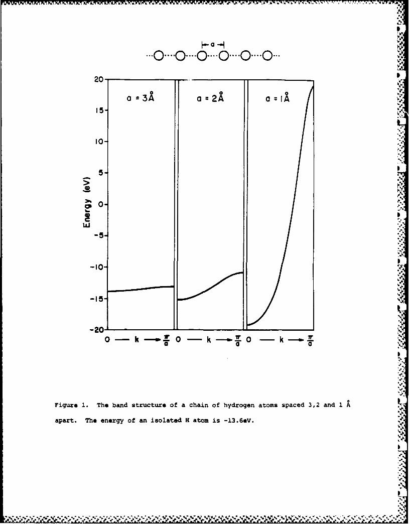
One very important feature of a band is its disersion, or
bdwi, the difference in energy between the highest and
lowest levels in the band. What determines the width of bands?
The same thing that determines the splitting of levels in a
dimer, ethylene or H2 , namely the overlap between the interacting
orbitals (in the polymer the overlap is that between neighboring
unit cells). The greater the overlap between neighbors, the
greater the band width. Fig. 1 illustrates this in detail for a
chain of H atoms spaced 3,2 and 1 A apart. That the bands extend
Figure 1
unsymmetrically around their "origin", the energy of a free H
atom at -13.6eV, is a consequence of the inclusion of overlap in
the calculations. For two levels, a dimer:
SHAA ± HAB
1± SAB
The bonding E+ combination is less stabilized than the
antibonding one E_ is destabilized. There are nontrivial
consequences in chemistry, for this is the source of 4-electron
repulsions and steric effects in one-electron theories.11 A
similar effect is responsible for the bands "spreading up" in
Fig. 1.
.0-....0 .... 0 .... 0 .... 0 .... 0.-.
20- _
000
15-
10-
€N
-P 0-
5
0 k
Figure 1. The band structure of a chain of hydrogen atoms spaced 3,2 and 1
apart. The energy of an isolated H atom is -13.6eV.

-JWVUU .lllo- -- - - - wv
15
°4
See How They Run
Another interesting feature of bands is how they "run". The
lovely mathematical algorithm 6 applies in general; it does not
say anything about the energy of the orbitals at the center of
the zone (k - 0) relative to those at the edge (k = x/a). For a
chain of H atoms it is clear that E(k = 0) < E(k = x/a). But
consider a chain of p functions, 9. The same combinations are
given to us by the translational symmetry, but now it is clearly
k = 0 which is high energy, the most antibonding way to put
together a chain of p orbitals.
k..- /.5 E E W)
0
The band of s functions for the hydrogen chain "runs up",
the band of p orbitals "runs down" (from zone center to zone
edge). In general, it is the topology of orbital interactions
which determines which way bands run.
Let me mention here an organic analogue to make us feel
comfortable with this idea. Consider the through-space
oe

16
10 I
interaction of the three x bonds in 10 and 11. The three-fold
symmetry of each molecule says that there must be an a and an e
combination of the x bonds. And the theory of group
representations gives us the symmetry adapted linear
combinations: for a: x + X + X , for e (one choice of an
infinity): , - + , where x is the w orbital of
double bond 1, etc. But there is nothing in the group theory
that tells us whether a is lower than e in energy. For that, one
needs chemistry or physics. It is easy to conclude from an
evaluation of the orbital topologies that a is below e in 10, but
the reverse is true in 11.
To summarize: band width is set by inter-unit-cell overlap.
and the way bands run is determined by the tODOlov Of that
o l

17 .5..
I
An Eclieed Stack of Pt(III Scuare Planar Complexes .
Let us test the knowledge we have acquired on an example a
little more complicated than a chain of hydrogen atoms. This is
an eclipsed stack of square planar d8 PtL 4 t-omplexes, 12. The
normal platinocyanides (e.g. K2Pt(CN)4 ) indeed show such stacking
in the solid state, at the relatively uninteresting Pt...Pt
separation of -3.3 A. more exciting are the partially oxidized
materials, such as K2Pt(CN)4C 0 .3 , K2Pt(CN)4 (FHF)0 .25 . These are
also stacked, but staggered, 13, with a much shorter Pt Pt
contact of 2.7 - 3.0 A. The Pt-Pt distance had been shown to be Il
inversely related to the degree of oxidation of the material.12
I
2a
p- 2- ,,
13
The real test of understanding is predicticn. So, let's try
to predict the approximate band structure of 12 and 13 without a
calculation, just using the general principles we have at hand.
Let's not worry about the nature of the ligand - it is usually
CN-, but since it is only the square planar feature which is ..,.
.5%
,IV
.5 . Vt .5 ~ . ... ~5 ~~. .. '. 4. Y .V' -\ ., ~ '. .N * ~- ,, *

181
likely to be essential, let's imagine a theoretician's generic
ligand, H-. And let's begin with 12, because the unit cell in it
is the chemical PtL4 unit, whereas in 13 it is doubled, (PtL4 )2.
One always begins with the monomer. What are its frontier
evels? The classical crystal field or molecular orbital picture
of a square planar complex (Fig. 2) leads to a 4 below 1
splitting of the d block.11 For 16 electrons we have z2 , xz, yz,
and xy occupied and x2-y2 empty. Competing with the ligand-
Figure 2
field-destabilized x2-y2 orbital for being the lowest unoccupied
molecular orbital (LUMO) of the molecule is the metal z. These
two orbitals can be manipulated in understandable ways: -
acceptors push z down, w-donors push it up. Better a-donors pushx2-y2 up.
We form the polymer. Each MO of the monomer generates a
band. There may (will) be some further symmetry-conditioned
mixing between orbitals of the same symmetry in the polymer (e.g.
s and z and z2 are of different symmetry in the monomer, but
certain of their polymer MO's are of the same symmetry). But a
good start is made by ignoring that secondary mixing, and just
developing a band from each monomer level independently.
First a chemist's judgment of the band widths that will
develop: the bands that will arise from z2 and z will be wide,
those from xz, yz of medium width, those from x2-y2 , xy narrow,
*6"

t IS U
- -- m yz- - xz
4L
Pt L-Pt-L L- '-L
zy
Figure 2. Molecular orbital derivation of the frontier orbitals of a square
planar PtL4 complex.
%U--N__

W-I -ii br. W*. Wit .. t...*.. WA I
19
II
is. yx
14
as shown in 14. This characterization follows from the
realization that the first set of interactions (z, z2) is a type,
thus has a large overlap between unit cells. The xz, yz set has
a medium w overlap, and the xy and x2-y2 orbitals (the latter of
course has a ligand admixture, but that doesn't change its
symmetry) are 6.
It is also easy to see how the bands run. Let's write out
the Bloch functions at the zone center (k - 0) and zone edge (k =
x/a). Only one of the * and 6 functions is represented in 15.
The moment one writes these down, one sees that the z2 and xy
bands will run "up" from the zone center (the k = 0 combination
is the most bonding) while the z and xz bands will run "down"
(the k - 0 combination is the most antibonding).
4.. J k' 2 : "€ . .': 2 . ' " g "-".' .' €.':2 .. .. ' c' ' " ", "4.

20
k 0 & k a ir/a
KY
is z
fs 5
The predicted band structure, merging considerations of band I
width and orbital topology, is that of 16. To make a real
E
it , YZ
AVo
0 -- k- - w/o ,.
161
estimate one would need an actual calculation of the various
overlaps, and these in turn would depend on the Pt---.Ptseparation.-
The actual band structure, as it emerges from an extended .
Mickel calculation at Pt-Pt - 3.0 A, is shown in Fig. 3. It .
matches our expectations very precisely. There are, of course,
'4/.',,..-,,",,% ,," -,, .'.'..'- - v : ; ; ', ? - ":,',,'-.'.- .. " .-". ".".- -?.."-".'i.'";"-i'.i-. ':- "'""-'-' - .

21
bands below and above the frontier orbitals discussed -- these
are Pt-H a and a* orbitals.
Figure 3
To make a connection with molecular chemistry: the
construction of 16, an approximate band structure for a
platinocyanide stack, involves no new physics, no new chemistry,
no new mathematics beyond what every chemist already knows for
one of the most beautiful ideas of modern chemistry - Cotton's
construct of the metal-metal quadruple bond.13 If we are asked
to explain quadruple bonding, for instance in Re2C182-, what we
do is to draw 17. We form bonding and antibonding combinations
10
from the z2 (a), xz, yz(x) and x2-y2 (6) frontier orbitals of each
ReCl4 - fragment. And we split a from a* by more than r from ,*,
which in turn is split more than 6 and 6*. What goes on in thr
infinite solid is precisely the same thing. True, there are a

z
.r
-6 -_ . _ _ _ _ _ _ 2 -Y 2
0
0'
9.
1 0.*
-'Cl
-'12 XZIyZ
xy
D/ *p4 z
. '
F3gUre 3. Computed band stuctu of an eclipsed PtH42
stack, spaced at3 . he orbital marked Xz,yz doub degenerate
V w

r
22
few more levels, but the translational symmetry helps us out with
that. It's really easy to write down the symmetry-adapted linear
cobntinthe Bloch functions.
I
I:
-4.'

23
The Fermi Level
It's important to know how many electrons one has in one's
molecule. Fe(II) has a different chemistry from Fe(III), and CRI
carbocations are different from CR3 radicals and CRj anions. In
the case of Re2ClJ-, the archetypical quadruple bond, we have
formally Re(III), d4 , i.e. a total of eight electrons to put into
the frontier orbitals of the dimer level scheme, 17. They fill
the a, two x and the 6 level for the explicit quadruple bond.
What about the [PtHJ-], polymer 12? Each monomer is d8 . If
there be Avogadro's number of unit cells, there will be
Avogadro's number of levels in each bond. And each level has a
place for two electrons. So the first four bands are filled, the
xy, xz, yz, z2 bands. The Fermi level, the highest occupied -]
molecular orbital (HOMO), is at the very top of the z2 band.
(Strictly speaking, there is another thermodynamic definition of
the Fermi level, appropriate both to metals and semiconductors9,
but here we will use the simple equivalence of the Fermi level
with the HOMO.)
Is there a bond between platinums in this [PtH-], polymer?
We haven't introduced, yet, a formal description of the bonding
properties of an orbital or a band, but a glance at 15 and 16
will show that the bottom of each band, be it made up of z2, xz,
yz or xy, is bonding, and the top antibonding. Filling a band
completely, just like filling bonding and antibonding orbitals in Ia dimer (think of He2 , think of the sequence N2 , 02, F2 , Ne2)
I

24
provides no net bonding. In fact, it gives net antibonding. So
why does the unoxidized PtL4 chain stack? It could be van der
Waals attractions, not in our quantum chemistry at this primitive
level. I think there is also a contribution of orbital
interaction, i.e. real bonding, involving the mixing of the z2 V
and z bands.14 We will return to this soon.
The band structure gives a ready explanation for why the
Pt Pt separation decreases on oxidation. A typical degree of
oxidation is 0.3 electrons per Pt.12 These electrons must come
from the top of the z2 band. The degree of oxidation specifies
that 15% of that band is empty. The states vacated are not
innocent of bonding. They are strongly Pt-Pt a antibonding. So 'S
it's no wonder that removing these electrons results in the
formation of a partial Pt-Pt bond.
The oxidized material also has its Fermi level in a band,
i.e. there is a zero band gap between filled and empty levels.
The unoxidized platinocyanides have a substantial gap -- they are
semiconductors or insulators. The oxidized materials are good
low-dimensional conductors, which is a substantial part of what
makes them interesting to physicists.14
In general, conductivity is not a simple phenomenon to
explain, and there may be several mechanisms impeding the motion
of electrons in a material. 9 A prerequisite for having a good
electronic conductor is to have the Fermi level cut one or more
bands (soon we will use the language of density of states to say

25
this more precisely). One has to beware, however, 1) of
distortions which open up gaps at the Fermi level and 2) of very
narrow bands cut by the Fermi level, for these will lead to
localized states and not to good conductivity.9
4.
p
4.4
I
p

26
More Dimensions. At Least Two
Most materials are two- or three-dimensional, and while one
dimension is fun, we must eventually leave it for higher
dimensionality. Nothing much new happens, except that we must
treat i as a vector, with components in reciprocal space, and the
Brillouin zone is now a two- or three-dimensional area or
volume.9,15
To introduce some of these ideas, let's begin with a square
lattice, 18, defined by the translation vectors al and a2.
Suppose there is an H is orbital on each lattice site. It turns
out that the Schr6dinger equation in the crystal factors into
separate wave equations along the x and y axes, each of them
identical to the one-dimensional equation for a linear chain.
There is a kx and a ky, the range of each is O IkxI,IkyIw/a
(a=lall=l2l2 ). Some typical solutions are shown below, in 19.
The construction of these is obvious. What the construction
also shows, very clearly, is the vector nature of k. Consider
the (kx, ky) = (*/2a, x/2a) and (*/a, r/a) solutions. A look at
them reveals that they are waves running along a direction which
N.N.% %'W %

27
rk,90. kysO
kx-lr/2a, kyO k,, ky r'/2a k, a 0, k),, V/20..
k1,l r/a, kyO k r,/ky a /O, ,'0 ky'r/a
x M X
is the vector sum of kx and ky, i.e. on a diagonal. The wave
length is inversely proportional to the magnitude of that vector.
The space of k here is defined by two vectors 81 and 82 , and
the range of allowed k, the Brillouin zone, is a square. Certain
special values of k are given names: r = (0, 0) is the zone
center, X = (*/a, 0) = (0, x/a), M = (x/a, x/a). These are shown
in 20, and the specific solutions for r, X, M were so labeled in
19.
r
It is difficult to show the energy levels, E(!) for all .
So what one typically does is to illustrate the evolution of E
along certain lines in the Brillouin zone. Some obvious ones are

, .'
28
r - X, r - M, X -M. From 19 it is clear that M is the highest
energy wave function, and that X is pretty much nonbonding, since
it has as many bonding interactions (along y) as it does
antibonding ones (along x). So we would expect the band
structure to look like 21.S.
IiI
/p
21\I
r X M r
A computed band structure and DOS for a hydrogen lattice with a =
2.0 A, Fig. 4, confirms our expectations.
Figure 4
do
The chemist would expect the chessboard of H atoms to
distort into one of H2 molecules (An interesting problem is howI
many different ways there are to accomplish this). The large
peak in the DOS for the half-filled H s-uare lattice band would
make the physicist think of a lattice vibration that would create
a gap at eF. Any pairwise deformation will do that.
Let's ncw put some p orbitals on the square lattice, with
the direction perpendicular to the lattice taken as z. The Pz
orbitals will be separated from py and Px by their symmetry. S

H Square Net
U 4U
-to4
r1 -10rDO
Fiue4 h adsrcueadDSo qaeltieoatmHHsprto .

29
Reflection in the plane of the lattice remains a good symmetry
operation at all k. The pz(z) orbitals will give a band
structure similar to that of the s orbital, for the topology of
the interaction of these orbitals is similar. This is why in the
one-dimensional case we could talk at one and the same time about
chains of H atoms and polyenes.
The Px, Py (x, y) orbitals present a somewhat different
problem. Shown below in 22 are the symmetry-adapted combinations
PI
ExxOle qi,'
OKOI-0 010 M r, 4-
ckaeko_0
UI~1r* o71

30
of each at r, X, Y, and M. (Y is by symmetry equivalent to X;
the difference is just in the propagation along x or y.) Zach
crystal orbital can be characterized by the p,p a or r bonding .1
present. Thus at r the x and y combinations are a antibonding
and r bonding; at X they are a and * bonding (one of them), and
and x antibonding (the other). At M they are both a bonding, if
antibonding. It is also clear that the x, y combinations are
degenerate at r and X (and it turns out along the line r - M, but
for that one needs a little group theory15 ) and non-degenerate at
X and Y (and everywhere else in the Brillouin zone).
Putting in the estimate that a bonding is more important
than * bonding, one can order these special symmetry points of A
the Brillouin zone in energy and draw a qualitative band 1
structure. This is Fig. 5. The actual appearance of any real .
band structure will depend on the lattice spacing. Band
Figure 5
dispersions will increase with short contacts, and complications
due to s, p mixing will arise. Roughly, however, =ny square
lattice, be it the P net in GdPS16 , a square overlayer of S atoms
p
U4.

ky
-X- N"]-V--& ,%~ , r ~- 4 .~ C~YC Y~ ~' ~ ~ .M
" U '
1 " X M I 'I'I
O.
0
A.
w
kS
,'
Figure 5. Schematic band structure of a planar square lattice of ,:atoms bearing ns and np orbitals. The s and p levels have a
large enough separation that the s and p band do not overlap. ""'
O

31
absorbed on Ni(100)17 the oxygen and lead nets in litharge18 a
Si layer in BaPdSi3 19 , any square lattice will have these
orb itals.
% .9
S

32
Setting UD a Surface Problem
The strong incentive for moving to at least two dimensions
is that one obviously needs this for studying surface bonding
problems. Let's begin to set these up. The kind of problem that
we want to investigate is how CO chemisorbs on Ni, how H2
dissociates on a metal surface, how acetylene bonds to Pt(111)
and then rearranges to vinylidene or ethylidyne, how surface
carbide or sulfide affects the chemistry of CO, how CH3 and CH2
bind, migrate, and react on an iron surface. It makes sense to
look first at structure and bonding in the stable or metastable
waypoints, the chemisorbed species. Then one could proceed to
construct potential energy surfaces for motion of chemisorbed
species on the surface, and eventually for reactions.
The very language I have used here conceals a trap. It puts
the burden of motion and reactive power on the chemisorbed
molecules, and not on the surface, which might be thought
passive, untouched. Of course, this can't be so. We know that
exposed surfaces reconstruct, i.e. make adjustments in structure
driven by their unsaturation.20 They do so first by themselves,
without any adsorbate. And they do it again, in a different way,
in the presence of adsorbed molecules. The extent of
reconstruction is great in semiconductors and extended molecules,
in general small in molecular crystals and metals. It can also
vary from crystal face to face. The calculations I will discuss
deal with metal surfaces. One is then reasonably safe (we hope)

33
if one assumes minimal reconstruction. It will turn out,
however, that the signs of eventual reconstruction are to be seen
even in these calculations.
It might be mentioned here that reconstruction is not a
phenomenon reserved for surfaces. In the most important
development in theoretical inorganic chemistry in the seventies,
Wade2la and Mingos2lb have provided us with a set of skeletal
electron pair counting rules. These rationalize the related
geometries of borane and transition metal clusters. One aspectS
of their theory is that if the electron count increases or
decreases from the appropriate one for the given polyhedral
geometry, that the cluster will adjust geometry -- open a bond
here, close one there -- to compensate for the different electron
count. Discrete molecular transition metal clusters and
polyhedral boranes also reconstruct.
Returning to the surface, let's assume a specific surface
plane cleaved out, frozen in geometry, from the bulk. That piece
of solid is periodic in two dimensions, semi-infinite, and
aperiodic in the direction perpendicular to the surface. Half of
infinity is much more painful to deal with than all of infinity,
because translational symmetry is lost in that third dimension.
And that symmetry is essential in simplifying the problem -- one p
doesn't want to be diagonalizing matrices of the degree of vAvogadro's number; with translational symmetry and the apparatus ',
of the theory of group representations one can reduce the problem
to the size of the number of orbitals in the unit cell.
p
~ 'x

~34
So one chooses a slab of finite depth. 23 shows a four-
layer slab model of a (111) surface of an fcc metal, a typical
close-packed hexagonal face. How thick should the slab be?
AICA
23
Thick enough so that its inner layers approach the electronic
properties of the bulk, the outer layers those of the true
surface. In practice, it is more often economics which dictates
the typical choice of three or four layers.
Molecules are then brought up to this slab. Not one
molecule, for that would ruin the desirable two-dimensional
symmetry, but an entire array or layer of molecules maintaining
translational symmetry.2 2 This immediately introduces two of the
basic questions of surface chemistry: coverage and site
preference. 24 shows a c(2x2)CO array on Ni(100), on-top
Q NI
00
2'I
Ni ,

35
adsorption, coverage = 4. 25 shows four possible ways of
adsorbing acetylene in a coverage of k on top of Pt(lll). The
a b
air
hatched area is the unit cell. The experimentally preferred mode
is the three-fold bridging one, 25c. Many surface reactions are
coverage dependent.2 And the position where a molecule sits on a
surface, its orientation relative to the surface, is one of the
things one wants to know.
So: a slab, three or four atoms thick, of a metal, and a
monolayer of adsorbed molecules. Here's what the band structure
looks like for some CO monolayers (Fig. 6) and a four layer
Ni(100) slab (Fig. 7). The phenomenology of these band
structures should be clear by now:
Figures 6 and 7
1) What is being plotted: E vs. 1L The lattice is two-
dimensional. k is now a vector, varying within a two-
*1f 1 ~ 3 4\ fp.~*- ,< 4' 4... v~ .~ . __

0 0 000I.
I-:C .. . ' I."
)o.... -.C-.-.c T.:..-
0 10 --,.s-
-,o C
q,1
'1"
U
50" ............
4a,
X M r x M P
Figure . Band structures of square monolayers of CO at two separations:
I (a) left, 3.52 , (b) right, 2.49 X.These would correspond to and full
coverage of a Ni (100) surface.".I
.,

Cw
-10
Ni
4 layer slab
Figure?. The band structure of a four-layer Ni slab that serves as a model
for a Ni(iO0) surface. Th., flat bands are derived from Ni 3d, the more highly
dispersed ones above these are 4s, 4p.

36
dimensional Brillouin zone, I = (kx, ky). Some of the special
points in this zone are given canonical names: r(the zone
center) = (0, 0); X = (n/a, 0), M - (n/a, w/a). What is being
plotted is the variation of the energy along certain specific
directions in reciprocal space connecting these points.
2) How many lines there are: as many as there are orbitals
in the unit cell. Each line is a band, generated by a single
orbital in the unit cell. In the case of CO, there is one
molecule per unit cell, and that molecule has well-known 4a, 1x,
5a, 2** MO's. Each generates a band. In the case of the four-
layer Ni slab, the unit cell has 4 Ni atoms. Each has five 3d,
one 4s and three 4p basis functions. We see some, but not all,
of the many bands these orbitals generate in the energy window
shown in Fig. 7.
3) Where (in energy) the bands are: The bands spread out,
more or less dispersed, around a "center of gravity". This is
the energy of that orbital in the unit cell which gives rise to
the band. Therefore, 3d bands lie below 4s and 4p for Ni, and 5a
below 2w* for CO.
4) Why some bands are steeD. others flat: because there is
much inter-unit-cell overlap in one case, little in another. The
CO monolayer bands in Fig. 6 are calculated at two different
CO-CO spacings, corresponding to different coverages. It's no
surprise that the bands are more dispersed when the CO's are
closer together. In the case of the Ni slab, the s, p bands are

37J.
wider than the d bands, because the 3d orbitals are more
contracted, less diffuse than the s, p.
5) How come the bands are the way they are: They run up or
down along certain directions in the Brillouin zone as a
consequence of symmetry and the topology of orbital interaction.
Note the phenomenological similarity of the behavior of the a and
bands of CO in Fig. 6 to the schematic, anticipated course of
the s and p bands of Fig. 5.
There are more details to be understood, to be sure. But,
in general, these diagrams are complicated, not because of any
mysterious phenomenon, but because of richness, the natural
accumulation of understandable and understood components.
We still have the problem of how to talk about all these
highly delocalized orbitals, how to retrieve a local, chemical,
or frontier orbital language in the solid state. There is a way.
I
I
-

~38
Density of States
In the solid, or on a surface, both of which are just very
large molecules, one has to deal with a very large number of
levels or states. If there are n atomic orbitals (basis
functions) in the unit cell, generating n molecular orbitals, and
if in our macroscopic crystal there are N unit cells (N is a
number that approaches Avogadro's number), then we will have Nn
crystal levels. Many of these are occupied and, roughly
speaking, they are jammed into the same energy interval in which
we find the molecular or unit cell levels. In a discrete
molecule we are able to single out one orbital or a small
subgroup of orbitals (HOMO, LUMO) as being the frontier, or
valence orbitals of the molecules, responsible for its geometry,
reactivity, etc. There is no way in the world that a single
level among the myriad Nn orbitals of the crystal will have the
power to direct a geometry or reactivity.
There is, however, a way to retrieve a frontier orbital
language in the solid state. We cannot think about a single
level, but perhaps we can talk about bunches of levels. There
are many ways to group levels, but one pretty obvious one is to
look at all the levels in a given energy interval. The density
of states (DOS) is defined as follows:
DOS(E)dE - number of levels between E and E+dE
V' V. ?-'

39
For a simple band of a chain of hydrogen atoms, the DOS curve
takes on the shape of 26. Note that because the levels are
equally spaced along the k axis, and because the E(k) curve, the
band structure, has a simple cosine curve shape, there are more
tE E(k)E
0 k- V/4 0 00O -
states in a given energy interval at the top and bottom of this
band. In general, DOS(E) is proportional to the inverse of the
slope of E(k) vs. k, or to put it into plain English, the flatter
the band, the greater the density of states at that energy.
The shapes of DOS curves are predictable from the band
structures. Fig. 8 shows the DOS curve for the PtH- chain, Fig.
9 for a two-dimensional monolayer of CO. These could have been
sketched from their respective band structures. In general, the
detailed construction of these is a job best left for computers.
Figures 8 and 9
The density of states curve counts levels. The integral of
DOS up to the Fermi level is the total number of occupied MO's.
Multiplied by two, it's the total number of electrons. So, the
DOS curves plot the distribution of electrons in energy.
V,

z DOS (E-4-.
2- 2.
3.0 A
1-
>1'..
-1455
Pt-Ho
0 k 7r/a 0 Density of States
Figur. - Band structure and density of states for an eclipsed PtH4 2 stack.
The DOS curves are broadened so that the two-peaked shape of the xy peak in
the DOS is not resolved.

CO monolayer0 .0 *1--3-52 A-4C C
27r*
4)
5 ,J
w
40-
r XM I DOS-.I
Figure I. The density of states (right) corresponding to the band structure
(left) of a square monolayer of CO's, 3.52 $apart.
-r.

40
One important aspect of the DOS curves is that they
represent a return from reciprocal space, the space of k, to real
space. The DOS is an average over the Brillouin zone, over all k
that might give molecular orbitals at the specified energy. The
advantage here is largely psychological. If I may be permitted
to generalize, I think chemists (with the exception of
crystallographers) by and large feel themselves uncomfortable in
reciprocal space. They'd rather return to, and think in, real
space. 01
There is another aspect of the return to real space that is
significant: chemists can sketch the DOS of any material.
apDroximatelv. intuitively. All that's involved is a knowledge
of the atoms, their approximate ionization potentials and
electronegativities, and some judgment as to the extent of inter-
unit-cell overlap (usually apparent from the structure).
Let's take the PtHJ- polymer as an example. The monomer
units are clearly intact in the polymer. At intermediate
monomer-monomer separations (e.g. 3 A) the major inter-unit-cell
overlap is between z2 and z orbitals' Next is the xz, yz w-type
overlap; all other interactions are likely to be small. 27 is a
sketch of what we would expect. In 27 I haven't been careful in
drawing the integrated areas commensurate to the actual total
number of states, nor have I put in the two-peaked nature of the
DOS each level generates -- all I want to do is to convey the
rough spread of each band. Compare 27 to Fig. 8.

41
Monomer - ol ymer p
1 '5
22-y i %I| Y
A yPt-I.,Pt-0zy - ,
This was easy, because the polymer was built up of molecular
monomer units. Let's try something inherently three-dimensional.
The rutile structure is a relatively common type. As 28 shows,
the rutile structure has a nice octahedral environment of each
metal center, each ligand (e.g. 0) bound to three metals. There
are infinite chains of edge-sharing M06 octahedra running in one
direction in the crystal, but the metal-metal separation is
always relatively long.23 There are no monomer units here, just
an infinite assembly. Yet there are quite identifiable
octahedral sites. At each, the metal d block must split into t2gI
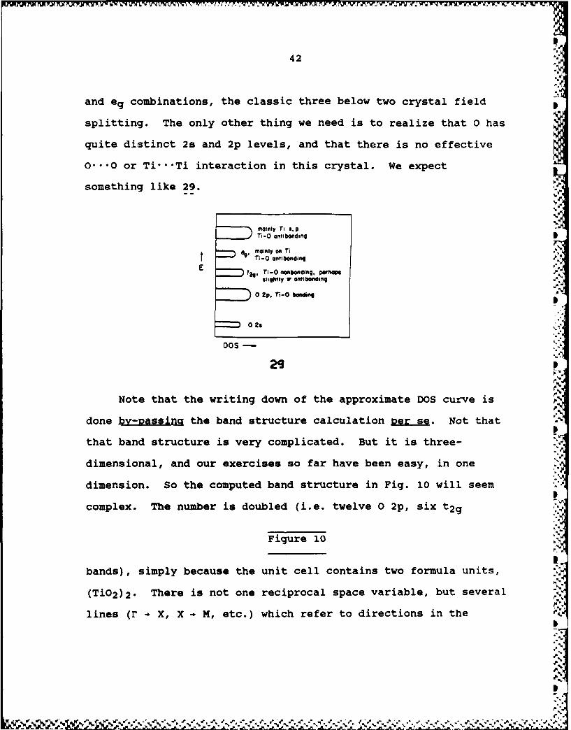
42at
and eg combinations, the classic three below two crystal field
splitting. The only other thing we need is to realize that 0 has
quite distinct 2s and 2p levels, and that there is no effective
o..O or Ti.. Ti interaction in this crystal. We expect
something like 29. ,e
mainly Ti spTi-0 oantlbo ding
mainly on Ti
S"-0 anibonding
t24. Ti-O nollnbding. pWhibgs Asligmtly antibofidilng
0 2p. Ti-O bonding
0o
DOS -
2S
Note that the writing down of the approximate DOS curve isA
done k pajng the band structure calculation per se. Not that
that band structure is very complicated. But it is three-
dimensional, and our exercises so far have been easy, in one
dimension. So the computed band structure in Fig. 10 will seem
complex. The number is doubled (i.e. twelve 0 2p, six t2g
Figure 10
bands), simply because the unit cell contains two formula units,
(Ti02 )2. There is not one reciprocal space variable, but several
lines (r - X, X N N, etc.) which refer to directions in the
d.'

-400
-N -- 6
.46
.,.,
'.36r x M r DO
Figure 10. Band structure and density of states for rutile, TiO2. The tWo
TiO distances are 2.04(2x), 2.07(4x) A in the assumed structure.
'.

43
three-dimensional Brillouin zone. These complications of moving
from one dimension to three we will soon approach. If we glance
at the DOS, we see that it does resemble the expectations of 21.
There are well-separated 0 2s, 0 2p, Ti t2g and eg bands.23
Would you like to try something a little (but not much) more
challenging? Attempt to construct the DOS of the new
.J.
superconductors based on the La2CuO4 and Y~a2Cu3O7 structures.
And when you have done so and found that these should be
conductors, reflect on how that doesn't allow you yet, did not
allow anyone, to predict that compounds slightly off these
stoichiometries would be remarkable superconductors.24
The chemists' ability to write down approximate density of
states curves should not be slighted. It gives us tremendous
power, and qualitative understanding, an obvious connection to
local, chemical viewpoints such as the crystal or ligand field
model. I want to mention here one solid state chemist, John B.
Goodenough, who has shown over the years, and especially in his
prescient book on "Magnetism and Chemical Bonding", just how good
the chemist's approximate construction of band structures can
be. 25ct
In 27 and 29, the qualitative DOS diagrams for PtHio and
Tio2 , there is, however, much more than a guess at a DOS. There
is a chemical characterization of the localization in real space
of the states (are they on Pt, on H; on Ti, on 0) and a
specification of their bonding properties (Pt-H bonding,

44
antibonding, nonbonding, etc.). The chemist sees right away, or
asks -- where in space are the electrons? Where are the bonds?
There must be a way that these inherently chemical, local
questions can be answered, even if the crystal molecular
orbitals, the Bloch functions, delocalize the electrons over the
entire crystal.
'aZ

45
Where are the Electrons?
One of the interesting tensions in chemistry is between the
desire to assign electrons to specific centers, deriving from an
atomic, electrostatic view of atoms in a molecule, and the
knowledge that electrons are not as localized as we would like
them to be. Let's take a two-center molecular orbital
# = clX1 + c2X 2
where X, is on center 1, X2 on center 2 and let's assume centers
1 and 2 are not identical, and that Xl and X2 are normalized, but
not orthogonal.
The distribution of an electron in this MO is given by *2.
should be normalized, so
1 = Jiti2dr = JlclXl+c2x2 12dr = C12+c22+2clS12
where S12 is the overlap integral between Xl and X2. This is how
one electron in 9 is distributed. Now it's obvious that C1 2 of
it is to be assigned to center 1, c22 to center 2. 2c1c2S 12 is
clearly a quantity that is associated with interaction. It's
called the overlap population, and we will soon relate it to the
bond order. But what are we to do if we persist in wanting to
divide up the electron density between centers 1 and 2? We wantall the parts to add up to 1 and c12+c22 won't do. We must
assign, somehow, the "overlap density" 2c1c2S 12 to the two
centers. Mulliken suggested (and that's why we call this a
Mulliken population analysis20 ) a democratic solution, splitting
2cLc 2S12 equally between centers 1 and 2. Thus center 1 is

46
assigned c12+c 1c 2S12 , center 2 c22+c1c2S12 and the sum is
guaranteed to add up to 1. It should be realized that the
Mulliken prescription for partitioning the overlap density, while
uniquely defined, is quite arbitrary.
What a computer does is just a little more involved, for it
sums these contributions for each atomic orbital on a given
center (there are several), over each occupied MO (there may be
many). And in the crystal, it does that sum for several k points
in the Brillouin zone, and then returns to real space by
averaging over these. The net result is a partitioning of the
total DOS into contributions to it by either atoms or orbitals.
We have also found very useful a decompostion of the DOS into
contributions of fragment molecular orbitals (FMO's) of MO's of
specified molecular fragments of the composite molecule. In the
solid state trade these are often called "projections of the DOS"
or "local DOS". Whatever they're called, they divide up the DOS
among the atoms. The integral of these projections up to the
Fermi level then gives the total electron density on a given atom
or in a specific orbital. Then, by reference to some standard
density, a charge can be assigned.
Fig. 11 and 12 give the partitioning of the electron density
between Pt and H in the PtH 42- stack, and between Ti and 0 in
rutile. Everything is as 27 and 29 predict, as the chemist knows
it should be -- the lower orbitals are localized in the more
electronegative ligands (H or 0), the higher ones on the metal.

47
Figures 11 and 12
Do we want more specific information? In TiO 2 we might want
to see the crystal field argument upheld. So we ask for the
contributions of the three orbitals that make up the t2g (xz, yz,
xy in a local coordinate system) and eg(z 2 , x2-y2) sets. This is -
also shown in Fig. 12. Note the very clear separation of the t2g
and eg orbitals. The eg has a small amount of density in the 0
2s and 2p bands (a bonding) and t2g in the 0 2p band (w bonding).
Each metal orbital type (t2g or eg) is spread out into a band,
but the memory of the near-octahedral local crystal field is veryclear.
In PtH 42 we could ask the computer to give us the z2
contribution to the DOS, or the z part. If we look at the z
component of the DOS in PtH4 2 , we see a small contribution in
the top of the z2 band. This is easiest picked up by the
integral in Fig. 13. The dotted line is a simple integration,
like an NMR integration. It counts, on a scale of 0 of 100% at
the top, what % of the specified orbital is filled at a given
energy. At the Fermi level in unoxidized PtH 4 2- 4% of the
states are filled.
Figure 13
How does this come about? There are two ways to talk about
this. Locally, the donor function of one monomer (z2) can 0
-'

J.
-6 . P t- H o - , xk y 2
0
0'.
C -I 0
Pt d band
,
Pt-H o-Pt
Density of States --- ,
Figure jI. The solid line is the Pt contribution to the total DOS (dashed 4
line) of an eclipsed PtH" stack. What is not on Pt is on the four H's.
.4.
:.¢ -, ,-.. -;-.. .. -,_-" v -,-. -. ," ,'-" ." .'-..-. .'.." ,"-, ., ,' -'_,"..q-. ." .'.'_." .' ". .. . . " " " " " " . ...-.-. '-, -

-2 Ti 06
in rutile in rutile
-8
-14
-2,-23 .°
-26-"
-29
"-352,- 4.1
DOS DOS--.
-5-
-2,'.
DOS--- DOS-.
-20 r
Figure 1Z. Contributions of Ti and 0 to the total DOS of rutile, TiOz are
-23 -
shown at top. At bottom, the tag and eq Ti contributions are shown; their
integration (on a scale of 0 to 100%) is given by the dashed line.
-29 -
-32 -
-35t ' A ' W ~ ~ .A '. ~ 9. - ' .-'".- OS'-" . DOS--" ., %.t'

0 Integration of DOS (00%
-10-
-- - ---. ----6 . - . ." -
-1 - -- -- - -
-8
>' -10
stack.Tenite lin isaitegrationsit of thS ria otibution
0',
* .
C I.
Fiw e1.z n otiuin otettlDSo nelpe t - V
stack. The doted line is an ntegration oftheZobtlcnrbto

48
interact with the acceptor function (z) of its neighbor. This is
shown in 30. The overlap is good, but the energy match is
poor.11 So the interaction is small, but it's there.
Alternatively, one could think about interaction of the Bloch
functions, or symmetry-adapted z and z2 crystal orbitals. At k =
0 and k = r/a, they don't mix. But at every interior point in
the Brillouin zone, the symmetry group of 9 is isomorphic to
C4v,15 and both z and z2 Bloch functions transform as a1 . So
they mix. Some small bonding is provided by this mixing. But it
is really small. When the stack is oxidized, the loss of this
bonding (which would lengthen the Pt-Pt contact) is overcome by
the loss of Pt-Pt antibonding that is a consequence of the
vacated orbitals being at the top of the z2 band.
I..
-. A ~ -ft ~~P -. r J -,~~S . .~ .. .. .. .. .. .Y .A .. .J V. . . .

49
The Detective work of Tracing Molecule-Surface Interactions:Decomposition of the DOS
For another i'lustration of the utility of DOS
decompositions let's turn to a surface problem. We saw in a
previous section the band structures and DOS of the CO overlayer
and the Ni slab separately (Fig. 6, 7, 9) . Now let's put them
together in Fig. 14. The adsorption geometry is that shown
earlier in 24, with Ni-C 1.8 A. Only the densities of states are
shown, based on the band structures of Fig. 7 and 9.27 Some of
the wriggles in the DOS curves also are not real, they're a
result of insufficient k-point sampling in the computation.
Figure 14
It's clear that the composite system c(2x2)CO-Ni(100) is
roughly a superposition of the slab and CO layers. Yet things
have happened. Some of them are clear -- the 5a peak in the DOS
has moved down. Some are less clear -- where is the 2w, and
which orbitals on the metal are active in the interaction?
Let's see how the partitioning of the total DOS helps us to
trace down the bonding in the chemisorbed CO system. Figure 15
Figure 15
shows the 5a and 2w* contributions to the DOS. The dotted line
is a simple integration of the DOS of the fragment of
contributing orbital. The relevant scale, 0 to 100%, is to be
read at top. The integration shows the total percent of the

04u In
0
C.) W% o o
- 4J
CL
(AS AbQ

~1W ~ PV' ~* ~= i...................................... - ,. .~ ~ ~ .,, ,~ .~ . .
0- 41
oo
004~4n
o bCD4.C3
o j4
CA 4- cm(U0.
S 4.1
co
ol u, a,
0 0
0. 4J
0 4. 1
44 C
C- a)~J .
w0 C
0 ~ ~ gfl~ ~ 0 - N f)
(AG) ABJGU3

50
given orbital that's occupied at a specified energy. It is clear
that the 5a orbital, though pushed down in energy, remains quite
localized. Its occupation (the integral of this DOS contribution
up to the Fermi level) is 1.62 electrons. The 2w * orbital
obviously is much more delocalized. It is mixing with the metal
d band, and, as a result, there is a total of 0.74 electrons in
the 2w* levels together.
Which levels on the metal surface are responsible for these
interactions? In discrete molecular systems we know that the
important contributions to bonding are forward donation, 31a,
from the carbonyl lone pair, 5a, to some appropriate hybrid on a
partner metal fragment, and back donation, 31b, involving the 2m*
III
MLn
ab
of CO and a d. orbital, xz, yz, of the metal. We would suspect
that similar interactions are operative on the surface.
These can be looked for by setting side by side the d,(z 2)
and 5a contributions to the DOS, and d(xz, yz) and 2,
contributions. In Fig. 16 the w interaction is clearest: note
.|
IV

51
Figure 16
how 2s* picks up density where the d. states are, and vice versa,
the d, states have a "resonance" in the 2K * density. I haven't
shown the DOS of other metal levels, but were I to do so, it
would be seen that such resonances are not found between those
metal levels and 5a and 2w . The reader can confirm at least
that 5a does not pick up density where d. states are, nor 2w *
where d. states are mainly found.27 There is also some minor
interaction of CO 2* * with metal p. states, a phenomenon not
analyzed here.28
Let's consider another system in order to reinforce our'I
comfort with these fragment analyses. In 25 we drew several
acetylene-Pt(lll) structures with coverage - k. Consider one of
these, the dibridged adsorption site alternative 25b redrawn in
32. The acetylene brings to the adsorption process a degenerate
set of high-lying occupied w orbitals, and also an important
unoccupied w* set. These are shown at the top of 33. In all
known molecular and surface complexes, the acetylene is bent.
This breaks the degeneracy of w and w*, some s character mixing
?r• 'A

-~3 -I, yzOfsurfce Ntom zz,yz of surface Niatom 2u*of CO 2vt ofC-. N1I(100) stab c(Wx)CO-NM~OO) c(2x2)CO-NM~OO) CO monoloyer
-5.
-12
-10
DOS- DOS- DOS- DOS-
-3 1of surfacesNltomn as of surface Ni atom 54P o CID Baof CO-- NlIlOO) slab c(Wx)CO-NIlOO) c(2x2)CO-Nl(lOO) CO monolayr
S-5e
_9W-10
-13
DOS- DOS- DOS- DOS-
Figure 16. "Interaction Diagrams" for 5a and 2ir* of c(2x)CO-Ni(100). The
extreme left and right panels in each case show the contributions of the
appropriate orbitals Wz for 5a, xz,yz for 2rr*) of a surface metal atom (left),
and of the corresponding isolated CO monolayer MO. The middle two panels
then show the contributions of the same fragment MO's to the DOS of the com-
posite chemisorption system.
F N

52
into the , and z, components which lie in the bending plane and
point to the surface. The valence orbitals are shown at the
bottom of 33. In fig. 17 we show the contributions of these
D-k-
valence orbitals to the total DOS of 33. The sticks mark the
positions of the acetylene orbitals in the isolated molecule. It
is clear that wand s* interact less than r. and o* of CO.2 9
Figure 17
A third system: in the early stages of dissociative H2
chemisorption, it is thought that H2 approaches perpendicular to
the surface, as in 34. Consider Ni(111), related to the Pt(111)
IIH '
surface we have discussed earlier. Fig. 18 shows a series of
three snapshots of the total DOS and its au*(H2) projection.30
These are computed at separations of 3.0, 2.5 and 2.0 A from the

......... .......o° ..................... °" '
- I \ '
t
44T. .-
. . . .. .. . . . .IA 4J
O u N 1060 c t2 -. 0 0
I _1 I4J ( . D
.I I i i_ 4.i) In 0
o c
". i . e a
............ 4
. "0
4J
I
. . . . . . . ... . . . . . . .. . . . . . . c uE
"
M- j V
Sb ' --. T^o -u
o t
LL. 4- .
UCAJ.... ofTO' T T )
(A I EU U

53
Figure 18
nearest H of H2 to the Ni atom directly below it. The ag orbital
of H2 (the lowest peak in the DOS in Fig. 18) remains quite
localized. But the au* interacts, is strongly delocalized, with
its main density pushed up. The primary mixing is with the Ni s,
p band. As the H2 approaches some au* density comes below the
Fermi level.
Why does au* interact more than ag? The classical
perturbation theoretic measure of interaction
IHijI 2
Ei0Ej 0
helps one to understand this. au* is more in resonance in
energy, at least with the metal s, p band. In addition, its
interaction with an appropriate symmetry metal orbital is greater
than that of ag, at any given energy. This is the consequence of
including overlap in the normalization:
1+ 1, (01±02)
/2 (1±Sl2)
The au coefficients are substantially greater than those in ag.
This has been pointed out by many people, but in the present
context importantly emphasized by Shustorovich and Baetzold.31-33
We have seen that we can locate the electrons in the
crystal. But...

"OX'
-
z)
Pit
01 I
" I 0,' I
- , . IS I
C N _
.... I I- le
oI 4
- .~V 4- A e . w
-- .o .,I .4,=
it~~S to ~
4J
CL 0
.lI-.- 4' >
4- -",
CL > ( I
to to
-b A - 0 +,
I rI
i'sI I
.,-l I I I *I
0 |1 .... I" I I ... .. . I" II I1"
a.. ..
01 to 0 t
I -I T w
Ir r' -r
:.: o, - ."+
_ .s . Ig " -" E
-.- ,0 -S -.
II*i n I I
o o , o , ,o '-
-- II T. IJ4.
(Ae) ,B~eu3 u .5
C b
.2 0
4- ','"

54
Where are the Bonds?
Local bonding considerations (see 27, 29) trivially lead us
to assign bonding characteristics to certain orbitals and,
therefore, bands. There must be a way to find these bonds in the
bands that a fully delocalized calculation gives.
It's possible to extend the idea of an overlap population to
a crystal. Recall that in the integration of %2 for a two-center
orbital, 2cLc 2S12 was a characteristic of bonding. If the
overlap integral is taken as positive (and it can always be
arranged so) then this quantity scales as we expects of a bond
order: it is positive (bonding) if cI and c2 are of the same
sign, and negative if c1 and c2 are of opposite sign. And the
magnitude of the "Mulliken overlap population", for that is what
2cLc 2S1 2 (summed overall orbitals on the two atoms, over all
occupied MO's) is called, depends on ci, cj, Sij.
Before we move into the solid, let's take a look at how
these overlap populations might be used in a molecular problem.
Fig. 19 shows the familiar energy levels of a diatomic, N2 , a
Figure 19
"density of states" plot of these (just sticks proportional to
the number of levels, of length one for a, two for r) and the
contributions of these levels to the overlap population. lag and
lau (not shown in the figure) contribute little, because Sij is
small between tight ls orbitals. 2ag is strongly bonding, 2au
NV,, , ..,,, ,;"; 4 ' . .?. .. ;. ,. :, .. ; ? ., ,; ? ? .--c. C-..-

3'a
-10. 7rg3o-
7ruu
20-
3 o- -o
-30-
9!
"DOS"--. k,/ ,S
Figure 19. the orbitals of N2 (left) and a "solid state way" to plot the
DOS and COOP curves for this molecule. The log and 1au orbitals are out
of the rpnge of this figure.
4))
,"
-30.
.j-a
F i g u r e , . , . T he-, ..o r b i t ..a-,-'s --o f : "2 ( l f ) . n.a. .ld s t t.w t.l o h

55
and 3ag are essentially non-bonding. These are best
characterized as lone pair combinations. u is bonding, g .
antibonding, 3aU the a* level. The right-hand side of Fig. 19
characterizes the bonding in N2 at a glance. It tells us that
maximal bonding is there for 7 electron pairs (counting lag and .4
lau); more or fewer electrons will lower the N-N overlap
population. It would be nice to have something like this for
extended systems.
A bond indicator is easily constructed for the solid. An
obvious procedure is to take all the states in a certain energy
interval and interrogate then as to their bonding proclivities,measured Ly the Mulliken overlap population, 2cicjSij. What we
are defining is an overlap-population-weighted density of states.
The beginning of the obvious acronym (OPWDOS) unfortunately bas
been preempted by another common usage in solid state physics.
For that reason, we have called this quantity COOP, for crystal
2rbital Qverlap population.34 It's also nice to think of the
suggestion of orbitals working together to make bonds in the I
crystal, so the word is pronounced "co-op".
To get a feeling for this quantity, let's think what a COOP
curve for a hydrogen chain looks like. The simple band structure
and DOS were given earlier, 26; they are repeated with the COOP
curve in 35.
To calculate a COOP curve, one has to specify a bond. Let's
take the nearest neighbor 1,2 interaction. The bottom of the
• S

56
band is 1,2 bonding, the middle non-bonding, the top antibonding.
The COOP curve obviously has the shape shown at
H -.-- H--- .... H.' ' " ..".. 'H ....
ant-a-boM11ng bonding-
E E
k DOS- - 0 + -
COOP
right in 35. But not all COOP curves look that way. If we
specify the 1,3 next-nearest-neighbor bond (silly for a linear
chain, not so silly if the chain is kinked), then the bottom and
the top of the band are 1,3 bonding, the middle anti-bonding.
That curve, the dotted line in the drawing 35, is different in
shape. And, of course, its bonding and antibonding amplitude is
much smaller because of the rapid decrease of Sij with distance.
Note the general characteristics of COOP curves -- positive
regions which are bonding, negative regions which are
antibonding. The amplitudes of these curves depend on the number
of states in that energy interval, the magnitude of the coupling
overlap, and the size of the coefficients in the MO's.
The integral of the COOP curve up to the Fermi level is the
total overlap population of the specified bond. This points us
to another way of thinking of the DOS and COOP curves. These are
i"" " . ... p

57
the differential versions of electronic occupation and bond order
indices in the crystal. The integral of the DOS to the Fermi
level gives the total numbe- electrons; the integral of the
COOP curve gives the total overlap population, which is not
identical to the bond order, but which scales like it. It is the
closest a theoretician can get to that ill-defined but
fantastically useful simple concept of a bond order.
To move to something a little more complicated than the
hydrogen or polyene chain, let's examine the COOP curves for the
PtH4 2- chain, Fig. 20 shows both the Pt-H and Pt-Pt COOP curves.
Figure 20 1.
The DOS curve for the polymer is also drawn. The
characterization of certain bands as bonding or antibonding is
obvious, and matches fully the expectations of the approximate
sketch 27. The bands at -14, -15eV are Pt-H a bonding, the band
at -6eV Pt-H antibonding (this is the crystal-field destabilized
x2-y2 orbital). It is no surprise that the mass of d-block
levels between -10 and -13 eV doesn't contribute anything to Pt-H
bonding. But of course it is these orbitals which are involved
in Pt-Pt bonding. The rather complex structure of the -10 to
-13eV region is easily understood by thinking of it as a
superposition of a (z2 -z2 ), x (xz, yz)-(xz, yz) and 6 (xy-xy)
bonding and antibonding, as shown in 36. Each type of bonding
generates a band, the bottom of which is bonding and the top
LAI..

(AO) A 6,1au 3
100
-W T
" I "
C O
CL
(1 0oo
0
4.)
00 0
) 4.)
0
... .
4-)
V 0
-4 0
.4.4
(AD 04 O.

58Schenmlc decomlpostio of the Pt d-block total COOP curv for PtH
-w-XZ,yZ a-xy Totol
36
-- + +- -- 0 +- -- 0 0- -- +
antibonding (see 35 and Fig. 3). The 6 contribution to the COOP
is small, because of the poor overlap involved. The large Pt-Pt
bonding region at -7eV is due to the bottom of the Pt z band.
We now have a clear representation of the Pt-H and Pt-Pt
bonding properties as a function of energy. If we are presented
with an oxidized material, then the consequences of the oxidation
on the bonding are crystal clear from Fig. 20. Removing
electrons from the top of the z2 band at -10eV takes them from
orbitals that are Pt-Pt antibonding, Pt-H nonbonding. So we
expect the Pt-Pt separation, the stacking distance, to decrease,
as it does.12
The tuning of electron counts is one of the strategies of
the solid state chemists. Elements can be substituted, atoms
intercalated, non-stoichiometries enhanced. Oxidation and
reduction, in solid state chemistry as in ordinary molecular
solution chemistry, are about as characteristic (but
experimentally not always trivial) chemical activities as one can
conceive. The conclusions we reached for the Pt-Pt chain were
simple, easily anticipated. Other cases are guaranteed to be

59
more complicated. The COOP curves allow one, at a glance, to
reach conclusions about the local effects on bond length (will
bonds be weaker, stronger) upon oxidation or reduction.
We showed earlier a band structure for rutile. The
corresponding COOP curve for the Ti-O bond (Fig. 21) is extremely
Figure 21
simple. Note the bonding in the lower, oxygen bands, and
antibonding in the eg crystal-field destabilized orbitals. The
t2g band is, as expected, Ti-O nonbonding.
Let's try our hand at predicting the DOS for something quite
different from PtH 42 or TiO 2 , namely a bulk transition metal,
the face-centered-cubic Ni structure. Each metal atom has as its
valence orbitals 3d, 4s, 4p, ordered in energy approximately as
at the left in 37. Each will spread out into a band. We can
4p4
6. 0 band
d bow
OOS-
make some judgment as to the width of the bands from the overlap.
The s, p orbitals are diffuse, their overlap will be large, and a
wide band will result. They also mix with each other

Fiur 21-O6n T- OPfo uie

60
extensively. The d orbitals are contracted, and so will give
rise to a relatively narrow band.
The computed DOS for bulk Ni (bypassing the actual band
structure) is shown in Fig. 22, along with the Ni s and p
contributions to that DOS. What is not s or p is d and s
contributions. The general features of 37 are reproduced. At
the Fermi level, a substantial part of the s band is occupied, so
that the calculated35 Ni configuration is d9g 15s0 -62p0 .23 .
Figure 22
What would one expect of the COOP curve for bulk Ni? As a
first approximation we could generate the COOP curve for each
band separately, as in 38a & b. Each band in 37 has a lower Ni-
Ni bonding part, an upper Ni-Ni antibonding part. The composite
6b G
d (~p Total '
-0. - -0. - -0. -0

0 100% 10 00% 1Bulk Ni Bulk NI
* s contribution p contribution
S.:.
..... .. .. ........ .. ....... ..,. ..... .,.. .
-5o
:" ..........
....... ...
. . . . . . ... ..
1...." ..-
3- *tl naseo to 100% gienatp
'U-..,
Ok%
%.
Figure 22. Total DOS (dashed line) and 4s and 4p contributions to it in "'
bulk Ni. Thc dotted line is an integration of thc occupation of a specified ,
o .±tal, on a scale of 0 to 100% given at top. -
... "
I -
* ' ; ::

61
is 38c. The computed COOP curve is in Fig. 23. The expectations
of 38c are met reasonably well. .
Figure 23
A metal-metal COOP curve like that of 38c or Fig. 23 is
expected for any transition metal. The energy levels might be
shifted up, they might be shifted down, but their bonding
characteristics are likely to be the same. If we assume that a
similar band structure and COOP curve hold for all metals (in the
solid state trade this would be called the rigid band model),
then Fig. 23 gains tremendous power. It summarizes, simply, the
cohesive energies of all metals. As one moves across the
transition series, the M-M overlap population (which is clearly
related to the binding or cohesive energy) will increase, peaking
at about 6 electrons/metal -- Cr, Mo, W. Then it will decreasetoward the end of the transition series and rise again for small
s, p electron counts. For more than 14 electrons, a metal is
unlikely; the net overlap population for such high coordination
becomes negative. Molecular allotropes with lower coordination
are favored. There is much more to cohesive energies and the
metal-nonmetal transition than this Still, a lot of physics and
chemistry flows from the simple construction of 38.
COOP curves are a useful tool in the tracing down of
surface-adsorbate interactions. Let's see, for instance, how
this indicator may be used to support the picture of CO
chemisorption that was described above. The relevant curve is in

10. loNi-Ni
*
-,6 -6.
"-°6 * -i°'
DOS .e-AnegrnS 0 Sondlng-.coop
Figure 23. The total DOS and nearest neighbor Ni-Nj COOP in bulk Ni.
p"%'

62 "N
Fig. 24. The solid line describes Ni-C bonding, the dotted line
C-O bonding. The C-O bonding is largely concentrated in orbitals
Figure 24
which are out of the range (below) this figure. Note the major
contribution to Ni-C bonding in both the 5a peak and the bottom
of the d band. The 5a contribution is due to a-bonding, 31a.
But the bottom of the d band contributes through w-bonding, 31b.
This is evident from the "mirroring" C-0 antibonding in the same
region. The antibonding component of that dr-2w* interaction is
responsible for the Ni-C and C-0 antibonding above the Fermi
level. 27
It may be useful to emphasize that these curves are not only
descriptive, but also form a part of the story of tracing down
interaction. For instance, supposing we were not so sure that it
is the d-2x* interaction which is responsible for a good part of
the bonding. Instead, we could have imagined x bonding between
1w and some unfilled d. orbitals. The interaction is indicated
schematically in 39. If this mixing were important, the d block
orbitals, interacting in an antibonding way with 1w below them,
should become in part Ni-C a jiflning and C-0 bonding. Nothing
of this sort is seen in Fig. 24. The C-C antibonding in the d
block region is, instead, diagnostic of 2w* mixing being
important.
W, _J'

antibonding bonding
--- Ni-C
......... C-0
-4.0-
S-6.0-27r*
C~t . .. 1. .................. :I .........
LU................... .... o- 8.0""
-I0.0 -d block
-12.0-
5cr
-14.0 "
Figure 21. Crystal orbital overlap population for CO, on-top, in a
c(2x2)CO-Ni(100) model. Representative orbital combinations are drawn out.

63
0 ,1
d7, 17r Q
M
Incidentally, the integrated overlap populations up to the
Fermi level are Ni-C 0.84, C-a 1.04. In free CO the
corresponding overlap population is 1.21. The bond weakening is
largely due to population of 2w* on chemisorption.
Another illustration of the utility of COOP curves is
provided next by a question of chemisorption site preference. On
many surfaces, including Pt(lll), a particularly stable dead end
in the surface chemistry of acetylene is ethylidyne, CCH 3.36 How
that extra hydrogen is picked up is a fascinating question. But
let's bypass that and think about where the CCH 3 wants to be. 40 p
shows three alternatives -- 1-fold or "on-top," 2-fold or
"bridging," and 3-fold or "capping." Experiment and theory show
a great preference for the capping site. Why? p
The important frontier orbitals of a carbyne, CR, are shown
in 41. The C 2p orbitals, the e set, are a particularly
attractive acceptor set, certain to be important in any chemistry p
.
-.4

64
CH3 C 3 CH
40
41
of this fragment. We could trace its involvement in the three
alternative geometries 40 via DOS plots, but instead we choose to
show in Fig. 25 the Pt-C COOP curve for 1-fold and 3-fold
adsorption.
Figure 25
In both on-top and capping sites the carbyne e set finds
metal orbitals to interact with. Bonding and antibonding
combinations form. The coupling overlaps are much better in the
capping site. The result is that the carbon-metal e-type
antibonding combinations do not rise above the Fermi level in the
1-fold case, but do so in the 3-fold case. Figure 25 clearly
shows this -- the bonding and antibonding combinations are
responsible for recognizable positive and negative COOP peaks.
* *.5

VV
.
00
== 0
oo 04W1
I I T T I T
410
a. 4j,
N-
"00
. w
0~ 0
'VI 01 .
c S
0o cmt
.T T T. -
(AaC -4su

65
The total surface-CCH3 overlap populations are 0.78 in the 1-fold
case, 1.60 in the 3-fold case. The total energy follows these
bonding considerations; the capping site is much preferred.29
With a little effort, we have constructed the tools --
density of states, its aet ^.'"ions, the crystal orbital
overlap population -- which allow us to move from a complicated,
completely delocalized set of crystal orbitals or Bloch functions
to the localized, chemical description. There is no mystery in
this motion. In fact, what I hope I have shown here is just how
much power there is in the chemists' concepts. The construction
of the prxjm DOS and bonding characteristics of a PtH42-
polymer, or rutile, or bulk Ni, is really easy.
Of course, there is much more to solid state physics than
band structures. The mechanism of conductivity, the remarkable
phenomenon of superconductivity, the multitude of electric and
magnetic phenomena that are special to the solid state, for these
one needs the tools and ingenuity of physics.9 But as for
bonding in the solid state, I think (some will disagree) there is
nothing new, only a different language.
7V
or V..

66
A Solid State Sauple Problem: The Th 2SL2_Structure
The preceding sections have outlined some of the theoretical
tools for analysis of bonding in the solid state. To see how
these ideas can be integrated, let's discuss a specific problem.
More than 200 compounds of AB2X2 stoichiometry adopt the
ThCr2Si2 type structure37 . But you are not likely to find any
mention of these in any -todern textbook of general inorganic
chemistry. Which just tells us something about the ascendancy of
molecular inorganic chemistry, especially transition metal
organometallic chemistry, in the last three decades. However,
these compounds are there, we know their structures and they have
interesting properties. A is typically a rare earth, alkaline
earth, or alkali element, B is a transition metal or main group
element, and X comes from group 15, 14, and occasionally 13.
Since the synthesis of AB2X2 with A - a rare earth element, by
Parthd, Rossi, and their coworkers, the unusual physical
properties exhibited by these solids have attracted much
attention. Physicists speak with enthusiasm of valence
fluctuation, p-wave or heavy fermion superconductivity and of
many peculiar magnetic properties of these materials. The very
structure of these materials carries much that is of interest to
the chemist.
The ThCr 2Si2 structure type for AB2X2 stoichiometry
compounds is shown in 42. It consists of B2X22 layers
interspersed with A2+ layers. The bonding between A and B2X2

67
layers appears largely ionic, which is why we write the charge
partitioning as A2+ and B2X22-. But in the B2X22- layer there is
indication not only of covalent B-X bonding, but also some metal-
metal B-B bonding. Typical metal-metal distances are in the
range of 2.7 - 2.9 A.
A way to describe the B2X2 layers in these compounds is to
imagine a perfect square-planar two-dimensional lattice of metal
atoms, above and below the four-fold hollows of which lie the
main group X atoms. This is shown in 43, below. The
42-11 0O Th A 098x-x I 0 C, 8
0 Si X
coordination environment of the metal (B) is approximately
tetrahedral in the main group elements (X), with four additional
square planar near neighbor metals. The coordination of the X
atoms is much more unusual -- they reside at the apex of a square
pyramid.
It may be noted here that there are alternative ways to
describe the layer structure. For instance, the B2X2 layer may
be thought of as being built up by sharing four of the six edges
of a BX4 tetrahedron by infinite extension in 2 dimensions, as in
44. Such packing diagrams, or alternative ways of looking at the

68
Ix
same structure are inherently useful -- a new view often leads to
new insight. I would just introduce a very personal prejudice,
voiced above, for views of structure that make as many
connections as possible to other subfields of chemistry. On that
basis, I would give a slight preference to 43 over 44 -- the
latter pulls one a little away from bonds.
There is a long X.-X contact within the layer, but what
becomes the main focus of this section is a remarkable tunable X
X contact between all layers, along the edges (and across top
and bottom faces) of the tetragonal unit cell 42. This contact
(dx-x) is the primary geometrical variable in these structures.
Sometimes dx-x is long, sometimes it is short. In Table 1
are shown two series of compounds studied by Mewis. 3 8 In these A
the cation is kept constant, and so is the main group element, P.
Only the metal varies.
Table 1 here

68a
Table 1. The X-X Distance in Some Phosphide Compounds of theAB 2X2 Type.
AB 2X2 dx-x (A) AB 2X2 dx- x (A)
CaCu 1 .7 5P2 2.25 SrCu 1 .7 5 P2 2.30
CaNi2 P2 2.30 SrCo2P2 3.42
CaCo2 P2 2.45 SrFe2 P2 3.43
CaFe2 P2 2.71
4i
.-
.%"
'
.. . .,- . . . . .

69
For reference the P-P distance in P4 is 2.21 A and 2.192 A
in Me2P-PMe2 . The P-P single bond distance in many compounds is
remarkably constant at 2.19-2.26 A. The P-P double bond and P-P
triple bond lengths are around 2.03 A and 1.87 A respectively.
It is clear that the short distances in the ThCr 2Si2-type
phosphides are characteristic of a full P-P single bond. The
long contacts, such as 3.43 A, imply essentially no bonding at
all. All the compounds known with a nonbonding X-.-X separation
contain metals from the left-hand side of the Periodic Table. In
fact, examination of all the structures reveals a trend. As one
moves left to right in the transition series, the P-P contact
shortens. Clearly there is an electronic effect of work here --
a P-.P bond is made or broken in the solid state. We would like
to understand how and why this happens.
Incidentally, let's see what happens if one takes a Zintl
viewpoint of these structures. The long P...P contact would be
associated with a filled octet p3-, the full P-P single bond with
a p-p4 . For a divalent A2+ we would be left with a metal in
oxidation state II for the case of no P...P bond, oxidation state
I for a single P-P bond. One could make some sense of the trend
in terms of the energetics of the various metal oxidation states,
but one way or another the Zintl picture has a difficult time
with intermediate distances. How does one describe a P.-.P bond
length of 2.72 A? A delocalized approach has no problems with
describing such partial bonding.
.
-~ VW ,V S,~S~~~*S 5 SjE.~V ~'Y ~ . %

70
Chong Zheng and 139 approached the AB2X2 structure,
represented by a typical BaMn2P2 compound, in stages. First
looked at a single two-dimensional Mn2P22- layer. Then we formed
a three-dimensional Mn2P22 sublattice by bringing many such
layers together in the third dimension.
Consider a single Mn2P2 layer, 43. The Mn-P distance is
2.855 A. The latter is definitely in the metal-metal bonding
range, so a wide band, delocalized picture is inevitable. But in
some hierarchy or ranking of interactions, it is clear the Mn-P
bonding is stronger than Mn-Mn. So let's construct this solid
conceptually or think of it in terms of first turning on Mn-P
bonding, and then Mn-Mn interaction.
The local coordination environment at each Mn is
approximately tetrahedral. If we had a discrete tetrahedral Mn
complex, e.g. Mn(PR3)4 , we might expect a qualitative bonding
picture such as 45. Four phosphine lone pairs, al+t 2 in
M (
MI_
mostlytly ' M.i. '
MiM
m M(PRS) 4 4PR 3

71
symmetry, interact with their symmetry match, mainly Mn 4s and
4p, but also with the t2 component of the Mn 3d set. Four
orbitals, mainly on P, P-Mn a bonding, go down. Four orbitals,
mainly on Mn, P-Mn a antibonding, go up. The Mn d block splits
in the expected two below three way.
Something like this must happen in the solid. In addition,
there are Mn-Mn bonding contacts in the layer, and these will
lead to dispersion in those bands which are built up from
orbitals containing substantial metal character. The combined
construction is shown in Figure 26.
Figure 26
Ca1 we see this local, very chemical bonding construction in
a delocalized band structure? Most certainly. The calculated
(extended Huckel) band structure and total density of states of a
single Mn2 P2 2- layer is illustrated in Fig. 27.
Figure 27
The unit cell is a rhomboid of two Mn and two P atoms. P is
clearly more electronegative than Mn, so we expect two mainly P
3s bands below six P 3p bands below 10 Mn 3d bands. The number
of bands in Fig. 27 checks. A decomposition of the DOS (Fig. 28)
confirms the assignment.
Figure 28
:' *
..9 ... , ,, - .- . '- - , . . . .- '-;."- . . . . .- .. ... . . ,. ,.. . ' . . . .' ' " ' '.."- , , > ,:,, -v," "° ,-" """ '' _-.

or
Mn~ =Mn s, p bandsMn 4p
Mn 4s "
J m Mn d bonds
Mn 3d
P3p ______- ______ P p bands
P 3s-"-.//=zz ., P s bands t
Separate atoms Mn-P bonding Extended interactions,turned on especially Mn... Mn '
bonding, turned on
Figure 26. A schematic picture of the Mn2P2 - layer band structure as Iderived by first turning on local Mn-P interactions and then the two-dimensional
periodicity and Mn-Mn interactions.

1. ~ %. %. ~ -. * ~. .. ~ %a. ~ a, -. * a .~ -. ~ ~ ~ a L ~., 4. a. 4. ~ a~ - - ~. .
4.
S
0
V.,.5 44
.a,.
.'
S.4.
N.4.
0
Na-.'.4
S.-
al-val-N
a'..
a.
a..
.4.
S
4.4~a%.4 al~
N
0a,
a,
a..._______________________________ _____________________ _______________________________________________________ 44
M P X DOS 0
0
-'.4.a N.
2-Figure 27. Band structure and DOS of a svigle Mn2P2 layer.
-44S.
4.
6
~ ~jaja a'w44~aa,~%~.. ~.a \~ a */.4.t~ ' ~ 5'. % 5,4. 4. ~ .

Z,
-40-4- Total DOS ,-
" -.-- Mn Contribution to"-6" DOS
_8I2 I-'
-.--- ::. -
-14 - ..o
_22- : -
'-'16 - -
CV
-20 , -
Density of States
Figure Z. Total DOS of the composite MnzP22- layer lattice (dashed line)
and the contributions of Mn orbitals to that DOS (solid line). What is not
on Mn is on P. "
5;i$'

72
What about the bonding characteristics predicted by the
qualitative bonding scheme 45. This is where a COOP curve is
useful, constructed in Fig. 29. Note that the two lower bands
(at -15 and -19eV), which by the previous decomposition were seen
to be mainly P, are Mn-P bonding, whereas the mainly metal bands
around -12eV are Mn-P nonbonding. The bunch of levels at
approximately -9eV is Mn-P antibonding -- it corresponds to the
crystal-field destabilized t2 level in 45. The bottom of the
mainly metal band is Mn-Mn bonding, the top Mn-Mn antibonding.
Everything is as expected.
Figure 29
An interesting, slightly different approach to the bonding
in the layer is obtained if we, so to speak, turn on Mn-Mn
bonding first, then Mn-P bonding by "inserting" or
"intercalating" a P sublattice. This is done in Fig. 30. At
left is the P sublattice. We see P 3s (around -19eV) and P 3p
(around -14eV) bands. Both are narrow, because the P atoms are
-4 A apart. The Mn sublattice (middle of Figure 30) shows a
nicely dispersed density of states (DOS). The Mn-Mn separation
is only 2.855 A. Thus we have a two-dimensional metal, with a
familiar wide s, p plus narrow d band pattern. The bottom part
of the DOS in the middle of Figure 30 is the 3d band, the top is
the lower part of the 4s, 4p band. At the right in Figure 30 is
the density of states of the composite Mn2 P2 layer. Note how the
d
OPA ~ ~ . ..

-4--Mn-Mn 0-
..... Mn-P 0-0
-8
-10-
12I
w
-18
-20
-22
-antibonding bondingCOOP
Figure 29. Crystal orbital overlap population curves for the Mn-Mn bonds
(solid line) and Mn-P bonds (dotted line) in the Mn2P22 - single layer.

individual P and Mn bunches of states repel each other on forming
the composite lattice. Note also how part of the Mn d band stays
where it is, part moves up. Here is the memory, within this
delocalized structure, of the local e below t2 crystal field
splitting. There is no more graphic way of showing that what
happens in the inorganic solid is similar to what happens in an
isolated inorganic molecule.
Figure 30
Still another, more chemical detail. Each phosphorus in the
slab is in an unusual coordination environment, at the apex of a
square pyramid of Mn atoms. A chemist looks for a lone pair, 46,
.
pointing away from the ligands. We can look for it,
theoretically, by focussing on its directionality. P 3pz should
contribute most to this lone pair, so we interrogate the DOS for
its z contribution, Fig. 31. The Pz orbital is indeed well
-localized, 70% of it in a band at approximately -15eV. Here is
the lone pair.
Figure 31

A.
Ju
Z4-
41
I
ID0 %
0 An
N (a Q3T 7
4.1 4.
Law..

-4
-6
-8
- -0
-10
-12
w -6 - - - ~- ----
-P-20-
-22_
Density of States
Figure 31. Phosphorus 3pz orbital ccntribution (dark area) to the total
DOS (dashed line) of the Mn2P22- single layer. The dotted line is an inte-
gration of the dark line, on a scale of 0 to 100%.

74
A point that can be made here is that localization in energy
spate (such as we see for the P Pz projection) implies
localization in real space. The easiest way to think this
through is to go back to the construction of bands at the
beginning of this book. The molecular orbitals of a crystal are
always completely delocalized Bloch functions. But there is a
difference between what we might call symmetry-enforced
delocalization (formation of Bloch functions, little overlap) and
real, chemical delocalization (overlap between unit cells). The
former gives rise to narrow bands, the latter to highly dispersed
ones. Turning the argument around, if one sees narrow bands,
that's a sign of chemical localization, whereas wide bands imply
real delocalization.
On to the three-dimensional solid. When the two-dimensional
Mn2P22 - layers are brought together to form the three-dimensional
solid (Mn2P22-, still without the counterions), the P 3pz
orbitals or lone pairs in one layer form bonding and antibonding
combinations with the corresponding orbitals in the layers above
or below. Figure 32 shows the P 3pz density of states at
interlayer P-P = 2.4 A. The wide band at -8 to -12eV is Mn 3d.
Figure 32
Below and above this metal band are P bands, and in these, quite
well localized, are P-P a and a* combinations, 47. These bands
are narrow, because the lateral P-P distance in long.
I .'

, LP.F r 7. 7 vN,'17-77 "I 77-;- % j
-4 ;0P
-6
-8 100I -I0--,----
! - a-a-a ----a a
a a'
-10
-- I 6 .a a. - a' a
* 22..* ... a
(dse ie o h he-im-ension-a - n- Iie - atie Th-hopors
on a cale f 0 -I00%.
-
-8
-20 0
-22 a
Density of States
Figure 32. Phosphorus 3 pz orbital contribution (dark area) to the total DOS
(dashed line) of the three-dimensional Mn2P22 - lattice. The phosphorus-
phosphorus bond length here is 2.4 A. The dotted line is an integration,
on a scale of 0 to 100%.

VU)NnWVV- - .1JW .7-7rX -17" IF-R O
75
ir
Perhaps it's appropriate to stop here and reflect on what
has happened. There are Avogadro's number of levels per atomic
orbital in the solid. It's all delocalized bonding, but with our
theoretical tools we have been able to see, quite localized in
energy, orbitals of a diatomic molecule. The localization in
energy reflects the validity of a localization in space, i.e. a
bond.
If the three-dimensional calculation is repeated at
different interslab or P.--P distances all that happens is that
the localized P-P a and a* bands occur at different energies.
Their splitting decreases with increasing P...P separation, as
one would expect from their respective bonding and antibonding
nature.
We are now in a position to explain simply the effect of the
transition metal on the P-P separation. What happens when the
transition metal moves to the right-hand side of the Periodic
Table? The increased nuclear charge will be more incompletely
screened and the d electrons more tightly bound. As a result,
the d band comes down in energy and becomes narrower. At the
same time, the band filling increases as one moves to the right
p.

76
in the transition series. The balance is complicated, and it is
important. 48 shows the result. For details the reader is
referred to the definitive work of 0. K. Andersen.40
top of d
r, V Cr AM hg Co NI
48 is the most important single graph of metal physics. It
is analogous in its significance to the plot of the ionization
potentials of atoms or diatomic molecules. At the right side of
the transition series, the area of concern to us, the Fermi level
falls as one moves to the right, the work function of the metal
increases.
Now imagine superimposed on this variable energy sea of
electrons the P-P a and a* bands for some typical, moderately,.
bonding P-P distance, 49. In the middle of the transition
series, the metal Fermi level is above the P-P a*. Both a and a .
are occupied, there is no resultant P-P bond. As P-P stretches
in response, the a* only becomes more filled. On the right side
of the transition series, the P-P a* is above the Fermi level of
the metal, and so is unfilled. The filled P-P a makes a P-P
A.-

77
d bands (E
Mn Fe Co No Cu
bond. Making the P-P distance shorter only improves
this
situation.
The steady, gradual variation of the P-P distance would seem
to be as inconsistent with the molecular orbital model shown here
as it was with the Zintl concept. This is not so. If we turn on
the interaction between the P atoms and the metal layer (and we
have seen before this interaction is substantial) we will get
mixing of P and Mn orbitals. The discontinuity of the above
picture (either single bond or no bond) will be replaced by a
continuous variation of P a and a orbitals' occupation between 2
and 0.
The experimentally observed trend has been explained. There
is much more to the AB2X2 structures than I have been able to
present here37 ,39 , of course. More important than the
rationalizations and predictions of the experimental facts that
one is able to make in this case, is the degree of understanding
one can achieve and the facility of motion between chemical and
physical perspectives.
I

78
The Frontier Orbital Perspective
The analytical tools for moving backward from a bani
calculation to the underlying fundamental interactions are at
hand. Now let's discuss the motion in the forward direction, the
model of orbitals and their interaction, as analyzed by
perturbation theory. In a sense we already used this in 27,
29 and in Fig. 26, the mental construction of what we anticipated
in building the Mn2P2 layer.
This is the frontier orbital picture. 11,41 A chemical
interaction (between two parts of a molecule) or reaction
(between two molecules) can be analyzed from the starting point
of the energy levels of the interacting fragments or molecules.
The theoretical tool one uses is perturbation theory. To second
order, the interactions between two systems are pairwise additive
over the MO's and each pair interaction is governed by the
expression:
AE = _ _ _ __2
Ei ° -Ej"
That's what a squiggly line in the interaction diagram 50
indicates.
Individual interactions may be classified according to the
total number of electrons in the two orbitals involved; thus@
and 0 in 51 are two-electron, © is four-electron, Q is zero-electron. Qandfare clearly stabilizing (see the right side of

79
i e
af
Sm
~b -- El
Sg E *
d-n-
A B
'o
50). This is where true bonding is found, with its range between
covalent (orbitals balanced in energy and extent in space) or
dative (orbitals unequal partners in interaction, charge transfer
from donor to acceptor an inevitable correlate of bonding).
( D
.1
A B
"-,
5Y-

Inteacton Oas o diect 80
Interaction Ohas no direct energetic consequences, since the
bonding combination is unoccupied. And interaction Qis
repulsive, because what happens when the overlap is included in
the calculations (52) is that the antibonding combination goes up
more than the bonding one goes down. The total energy is greater
than that of the separate isolated levels.11
The electronic energy levels of molecules are separated by
energies of the order of an electron volt. This makes them
quantum systems Rar excellence, and allows the singling out of
certain levels as controlling a geometrical preference or a
reactivity. For instance, in 50 acceptor level lb> of fragment A
is closer in energy to donor level 1g> of fragment B, compared to
Ih> and li>. If it should happen that the overlaps <bjh> and
<bli> are also much smaller than <big> then both the numerator
and the denominator of the perturbation expression single out the
b(A)-g(B) interaction as an important, perhaps the most
important, one. In general, it turns out that the highest

81
occupied molecular orbital (HOMO) or a small subset of higher
lying levels, and the lowest unoccupied molecular orbital (LUMO),
or some subset of unoccupied MO's, dominate the interaction
between two molecules. These are called the frontier orbitals.
They are the valence orbitals of the molecule, the orbitals most
easily perturbed in any molecular interaction. In them resides
control of the chemistry of the molecule.
It should be realized that this description, while of
immense interpretative power, is only a one-electron model. Top
analyze orbital interactions properly, in a many-electron way, is
not easy. The simple picture of 51 seems to be lost; competing
interaction or partition schemes have been suggested.4 2 One way p
to appreciate the problem a true many-electron theory has in -
analyzing interactions is to realize that the energy levels of A
and B are not invariant to electron transfer. They change in
energy depending on the charge: on fragments A and B a positive
charge makes all the energy levels go down, a negative charge go .
up. Actually realizing this, one has learned the most important
correction to the simple one-electron picture.
dt
N,

82
Orbital Interaction on a Surface
It is now clear that what the apparatus of densities of
states and crystal orbital overlap populations has done is to
restore to us a frontier orbital or interaction diagram way of
thinking about the way molecules bond to surfaces, or the way
atoms or clusters bond in three-dimensional extended structures.
Whether it is 2x* CO with di of Ni(100), or e of CR with some
part of the Pt(lll) band, or the Mn and P sublattices in Mn2P2 2 -
or the Chevrel phases discussed below, in all of these cases we
can describe what happens in terms of local action. The only
novel feature so far is that the interacting orbitals in the
solid often are not single orbitals localized in energy or space,
but bands.
A side-by-side comparison of orbital interactions in
discrete molecules and of a molecule with a surface is revealing.
53 is a typical molecular interaction diagram, 54 a molecule-
surface one. Even though a molecule is, in general, a
®
A 8 A Surface
SqA
53 "
\%. . ~ A, A% '~A~j % A, , ,% ., ~ ~ ~ % . *,A ~ A,

83 p
many-level system, let's assume, in the spirit of a frontier
orbital analysis, that a small set of frontier orbitals
dominates. This is why the squiggly lines symbolizing
interaction go to the HOMO and LUMO of each component.
Within a one-electron picture the following statements can
be made (and they apply to both the molecule and the surfaceI
unless specifically said not to do so).
(i) The controlling interactions are likely to be the two-
orbital, two-electron stabilizing interactions@ andQ.I
Depending on the relative energy of the orbitals and the quality
of the overlap, each of these interactions will involve charge
transfer from one system to the other. In interactionQ A is
the donor or base, B, or the surface, the acceptor or acid. In
interactionfJ these roles are reversed.
(ii) Interaction Qis a two-orbital, four-electron one. It
is destabilizing, repulsive, as 55a shows. In one-electron
theories, this is where steric effects, lone pair repulsions,
etc. are to be found. 1l 4 1 These interactions may be important.
They may prevent bonding, interactions QQ from being realized.
There is a special variant of this interaction which may occur in
the solid, but is unlikely in discrete molecules. This is
sketched in 55b -- the antibonding component of a four-electron,
two-orbital interaction may rise above the Fermi level. It will
dump its electrons at the Fermi level, and can no longerI
destabilize the system. Only the intersystem bonding combination
remains filled.
N-

84
repulsion attraction
Q b55
The effect on molecule-surface bonding is clear -- it isI
improved by this situation. What happens in the surface is less
clear; let's defer discussion until we get to interactionQ
(iii) Interaction@ involves two empty orbitals. In
general, it would be discounted as having no energetic
consequences. This is strictly true in molecular cases, 56a.
But in the solid, where there is a continuum of levels, the
result of such interaction may be that the bonding combination of I
the two interacting levels may fall below the Fermi level, 56b.
F "
now -no effect attraction
a b
56

85
Becoming occupied, it will enhance fragment A-surface bonding.
Again, there may be an effect on the surface, because it has to
supply the electrons for the occupation of that level.
(iv) Interaction @is something special to the metallic
solid, that comes from the states of the metal surface forming a
near continuum. The interaction describes the second order
energetic and bonding consequences of shifts of electron density
around the Fermi level. First order interactionsO 0 0 and
all will move metal levels up and down. These metal levels, the
ones that move, will belong to the atoms on the surface
interacting with the adsorbate. The Fermi level remains constant
-- the bulk and surface are a nice reservoir of electrons. So
electrons (holes) will flow in the surface and in the bulk
underneath it, in order to compensate for the primary
interactions. These compensating electrons or holes are,
however, not innocent of bonding themselves. Depending on the
electron filling, they may be ;onding or antibonding in the bulk,
between surface atoms not involved with the adsorbate, even in
surface atoms so involved, but in orbitals that are not used in
bonding to the chemisorbed molecule.
Before I leave this section, I should like to say quite
explicitly that there is little novel in the use my coworkers and
I have made of interaction diagrams and perturbation theory
applied to surfaces. A.B. Anderson43 has consistently couched
his explanations in that language, and so have Shustorovich and
1.
• i

86
Baetzold31 ,32 -- Shustorovich's account of chemisorption is based
on an explicit perturbation-theoretic model. There is a very
nice, quite chemical treatment of such a model in the work of
Gadzuk44 , based on earlier considerations by Grimley45 . van
Santen46 draws interaction diagrams quite analogous to ours.
Salem and his coworkers47 have developed a related perturbation
theory based on a way of thinking about catalysis that includes a
discussion of model finite Hackel crystals, privileged orbitals,
generalized interactions diagrams, and the dissolution of
adsorbate into catalyst bands. There are also other workers who
have discussed interaction diagrams, privileged orbital sets, or
orbital symmetry considerations in the solid.48 >
Let's make these interactions and interactions diagrams come
to life through some specific applications.
IN"
o.
.1

p
87
A Case Study: CO on Ni(100)
The Ni(100)-CO system already discussed26 seemed to provide
an excellent example of the primary two-electron interactions at
work. We found charge transfer from 5a (its population going
from 2.0 in the free CO to 1.62 in the CO-surface complex) and
back donation from the surface to 2w * (whose population rose from
0 to 0.74). Actually, there is an interesting wrinkle here, in
that the 4 and 0 electron interactions mentioned in point (3),
above, manifest themselves.
To set a basis for what we will discuss, let's prepare a
model molecular system for comparison. We'll build a metal-
carbonyl bond between a d6 ML5 system and a carbon monoxide. The
interaction diagram, 57, will be familiar to a chemist; the
acceptor function of the MLn fragment is provided by a low-lying
0 oC
MI-- c cT
hy 27 I
xz,yz 0
5o- 0
5o C I%
57

16
88
dsp hybrid.1 1 ,4 9 The two-electron bonding interactions are quite , ",'explicit. They result (M = Ni, L = H-, M-H 1.7 A, M-CO 1.9 A) in
a depopulation of 5a by 0.41, and a population of 2n * by 0.51
electrons. The metal functions involved in these interactions
react correspondingly: so xz,yz loses 0.48 electrons, and the
hybrid orbital gains 0.48. The net charge drifts are pretty S.
p
well-described by the sum of what happens in these orbitals: CO
as a whole gains 0.01e-, and the MLn fragment loses the same.
The information is summarized in Table 2.
If one just looks at the CO, what happens on the surface
seems to be similar, as I noted above. And the d7 orbitals,
xz,yz are depopulated in c(2x2)CO-Ni(100). But the da, the z2 ,
the surface analogue of the hybrid, actually loses electron
density on chemisorption of CO.
What is happening here is that the CO 5a is interacting with
the entire z2 band, but perhaps more with its bottom, where the
coupling overlap is greater. The z2 band is nearly filled (1.93
in the metal slab). The net 5a-da band interaction would be
repulsive, mainly due to four-electron two-orbital interactions,
were it not for the pushing of some antibonding combinations
above the Fermi level (see 58 for a schematic). The net result
is some loss of z2 density and concomitant bonding. 50
Where do those "lost" electrons go? Table 2 indicates that
some, but certainly not all, go to the CO. Many are "dumped" at
the Fermi level into orbitals that are mainly d band, but on the
S,

89
Table 2.0Some Electron Densities in a Model H5NiCO- and the c(2x2)Co- i.
NiH5 - NiH 5 (CO)- CO Ni(100) c(2x2)CO-Ni(100) CO
5a 1.59 2.0 5a -- 1.62 2.0
2 -- 0.51 0.0 2K* -- 0.74 0.0
hy 0.0 0.48 -- daa 1.93 1.43 --
d 4.0 3.52 -- d a 3.81 3.31 --
CO -- 10.01 10.0 CO -- 10.25 10.0
H5Ni 16.0 15.99 -- Nia 10. 1 7b 9.37 --
a) for those surface atoms which have CO on them. 4
b) this number is not 10.0, because the surface layer of the slab isnegative relative to the inner layer.
'.3
.
4.
4.
3='
~ .. ~y - r '%. '%% C%% %'~.% V.'~%%.~ ~.~~\', %
..-. . 5:5 ' .- ' '' 5" ' ; " . -;v% .- ;-;;. -';'. 'p. "%-.%% -' '",-'%Lv'.,S'.-.

90
50'
S.,J
inner metal atoms, or on surface atoms not under CO. We will return to
the bonding consequences of these electrons, interaction(®), in a while.
Before leaving this instructive example, I trust that point is not
lost that the primary bonding interaction 0and0, are remarkably alike
in the molecule and on the surface. These forward and back donations
are, of course, the consequence of the classical Dewar-Chatt-Duncanson
model of ethylene (or another fragment) bonding in an organometallic
molecule.5 1 In the surface case, this is often termed the Blyholder
model, the reference being to a perceptive early suggestion of such
bonding for CO on surfaces.4 1b More generally, interactionsDand@ are
the fundamental electronic origins of the cluster-surface analogy. This
is a remarkably useful construction of a structural, spectroscopic and
thermodynamic link between organometallic chemistry and surface
science.5 2
- .w - , - . -.

919
Barriers to ChemisorDtion
The repulsive two-orbital four-electron interaction that turns into
an attractive, bonding force when the electrons, rising in energy, are
dumped at the Fermi level is not just a curiosity. I think that it is
responsible for observed kinetic barriers to chemisorption and the
possible existence of several independent potential energy minima as aI
molecule approaches a surface.
Consider a model molecule, simplified here to a single occupied
level, approaching a surface. Some schematic level diagrams and anI
associated total energy curve are drawn in Fig. 33. The approach
Figure 33
coordinate translates into electron interaction. Far away there is just
repulsion, which grows as the molecule approaches the surface. But when
the antibonding combination is pushed up to the Fermi level, the
electrons leave it for the reservoir of hole states, empty metal band
levels. Further interaction is attractive.
This simple picture was first given, to my knowledge, by E.L.
Garfunkel and by C. Minot and their coworkers. 5 3 In reality, the
repulsion at large metal adsorbate distances will be mitigated and, in
some cases overcome, by attractive two-electron interactions of typeQ
or@ (see 54). But the presence of the interaction, I think, is quite
general. It is responsible, in my opinion, for some of the large
kinetic barriers to CO chemisorption and CH4 decomposition measured in
the elegant beam experiments of S.T. Ceyer, R.J. Madix and their
coworkers.5 4

0 -E ,."
1
Figure 33. A schematic drawing showing how the interactions of levels (bottom)
can lead to a potential energy curve (top) which has a substantial barrier
to chemisorption. R measures the approach of a molecule, symbolized by a ,.
single interacting electron pair, to a surface. At large R repulsive four-
electron interactions dominate. At some R (second point from left), the anti-
bonding combination crosses the Fermi level, and dumps its electrons. At
shorter R there is bonding.

92
In reality, what we are describing is a surface crossing. And
there may be not one, but several such, for it is not a single level,
but groups of levels which are "pushed" above the Fermi level. There
may be several metastable minima, precursor states, as a molecule
approaches a surface.5 5
In this section I have mentioned, for the second time, the bonding
consequences of emptying, at the Fermi level, molecular orbitals
delocalized over adsorbate and surface, and antibonding between the two.
Salahub5 0 and Anderson 5 6 stress the same effect. There is a close
relationship between this phenomenon and a clever suggestion made some
time ago by Mango and Schachtschneider5 7 on the way in which metal atoms(with associated ligands) lower the activation barriers for forbidden
concerted reactions. They pointed out that such electrons, instead of
proceeding on to high antibonding levels, can be transferred to th-
metal. We, and others, have worked out the details of this kind of
catalysis for some specific organometallic reactions, such as reductive
elimination.5 8 It's quite a general phenomenon, and we will return to
it again in a subsequent section.

93
Chemisorption is a Compromis
Consider again the basic molecule-surface interaction diagram 59,
now drawn specifying the bonding within each component. The occupied
orbitals of the molecule A are generally bonding or nonbonding within
antibonding antibondingin inAiG surface
bonding , bondingin A in
© surface
A Surface
59
that molecule, the unfilled orbitals of A are usually antibonding. The
situation on the metal depends on where in a band the Fermi level lies:
the bottom of the d band is metal-metal bonding, the top is metal-metal
anti'--nding. This is why the cohesive energy of the transition metals
reaches a maximum around the middle of the transition series. Most of
the metals of catalytic interest are in the middle or right part of the
transition series. It follows that at the Fermi level the orbitals are
generally metal-metal antibonding.
What is the effect of the various interactions on bonding within
and between the adsorbate and the surface? Interaction® and® are
% 5.\s .. 5 y%..i % . . V a' . '

94
easiest to analyze -- they bind the molecule to the surface, and in the
process they transfer electron density from generally bonding orbitals
in one component to antibonding orbitals in the other. The net result:
a bond is formed between the adsorbed molecule A and the surface. But
bonding within the surface and within A is weakened, 60.
Bonding
weakened
S strengthened
///////weakenedSurface
60
Schematically this is indicated in 60. What about interactions/
and®? For moderate interaction, ® is repulsive and® has no effect.
Neither does anything to bonding within A or the surface. When
interaction grows, and antibonding (0) or bonding (G) states are
swept past the Fermi level, these interactions provide molecule-surface
bonding. At the same time, they weaken bonding in A, transferring
electron density into antibonding levels and out of bonding ones. What
the effect of such strong interaction of type )or 4 or, more generally,
of second order electron shifts, type®D, is on bonding within the
surface -- that depends on the position of the Fermi level and the net
electron drift.
-Ii ..

- . . . . a ' . .: ' 'i - - J " "* J
95
The sum total of these interactions is still the picture of 60:
metal-adsorbate bonding is accomplished at the expense of bonding within
the metal and the adsorbed molecule. This is the compromise alluded to
in the heading of this section.
A specific case will illustrate this point, and show the way to an
important consequence of this very simple notion.
Earlier we drew four possible geometries for a layer of acetylene,
coverage = 4, on top of Pt(lll), 3. Table 2 shows some of the indices
of the interaction in the four alternative geometries, in particular the
occupations of the four acetylene fragment orbitals (r i')a t the
various overlap popu'itions, and calculated binding energies.
Table 3
The three-fold bridging geometry (3c) is favored, in agreement with
experiment and other theoretical results. 2 9 One should say right awayI
that this may be an accident -- the extended HUckel method is not
especially good at predicting binding energies. The two-fold (3b) and
four-fold (3d) sites are slightly less bound, but more stable than the
one-fold site, 3a. But this order of stability is not a reflection of
the extent of interaction. Let's see how and why this is so.
The magnitude of interaction could be gauged by looking at the
acetylene fragment orbital populations, or the overlap population. In
the detailed discussion of the two-fold site in an earlier section, we
saw w and i* more or less unaffected, r. depopulated, w,* occupied. Asaa consequence, Pt-C bonds are formed, the C-C bond weakened, and IP°

96
(interaction®) some Pt-Pt bonds on the surface weakened. A glance at
the fragment MO populations and overlap populations in Table 329 shows
that all this happens much more in the four-fold site 3d -- note that
even r and n* get strongly involved. The most effective interaction
here is that shown in 61. Note that it is primarily of type® .
2p
61
By any measure, interaction is least in the on-top or one-fold
geometry, most in the four-fold one. See, for instance, the trend in
C-C overlap populations, or the Pt-Pt bond weakening. In the four-fold
geometry one Pt-Pt overlap population is even negative -- bonding
between metal atoms in the surface is being destroyed. It is clear that
the favorable condition for chemisorption, or the preference of a
hydrocarbon fragment for a specific surfac. site, are determined by a
balance between increased surface-adsorbate bonding and loss of bonding
within the surface or in the adsorbed molecules.
Adsorbate induced surface reconstruction and dissociative
chemisorption are merely natural extremes of this delicate balance. In
each case, strong surface-adsorbate interactions direct the course of
the transformation, either breaking up bonding in the surface so that it
reconstructs, or disrupting the adsorbed molecule. 59 An incisive
1:

.?i"
97
Table 3. Bonding Characteristics of Several Acetylene Adsorption Sites on Pt(111).
C2H2 BrSurface 4, I
3.56 4.68 4.74 4.46 0(eV)
Overlap PopulationC-C 1.70 1.41 1.32 1.21 1.08Ptl-Pt2 0.14 0.12 0.08 0.09 -0.02
Pt2-Pt 3 0.14 0.14 0.13 0.07 0.06Ptl-Pt 4 0.14 0.13 0.13 0.15 0.06Ptl-Cb 0.30 0.54 0.52 0.33Pt3-C 0.00 0.01 0.19 0.27
Occuations I
0.0 0.08 0.17 0.33 0.53*o 0.0 0.81 1.06 1.03 0.89
'. 2.0 1.73 1.59 1.59 1.572.0 1.96 1.96 1.73 1.53
'
a Taken as the differenae: E(slab) + E(C2 H2 ) - E(geuktry) in eV.
b The carbon atcu here is the closest to the particular Pt atan under %
consideration.
oI
S.

98
discussion of the latter situation, for the case of acetylene on
iron and vanadium surfaces has been provided by A.B. Anderson.60
.,
p%
I
- .* -w-w * S ~ S S -!

99
Frontier Orbitals in Three-Dimensional Extended Structures
The frontier orbital way of thinking, especially with
respect to donor-acceptor interactions, if of substantial utility
in the solid state. Let me give one example here.
The Chevrel phases are a fascinating set of ternary
molybdenum chalcogenide materials of varying dimensionality and
interesting physical properties.6 1 In the parent phase,
epitomized by PbMo6S8 , one has recognizable Mo6S8 clusters. In
these clusters, shown in three views in 62, sulfurs cap the eight
ba
62.
faces of an octahedron of molybdenums. The Mo6S8 clusters are
then embedded in a substructure of lead cubes (this is a thought
construction of the structure!), as in 63. But the structure
doesn't remain here. In every cubical cell, the Mo6S8 rotates by
-26° around a cube diagonal, to reach structure 64 (Pb's are
missing in this drawing, for clarity).
Why? The answer is implicit in 64. A rotation of roughly
this magnitude is required to give each Mo within one unit a
fifth bonding interaction with a sulfur of a cluster in the

10
PP,
63 0Pb* MO
Ps.
0: x •s, S4,TG
neighboring cube. If one does a molecular orbital calculation on
the isolated cluster, Fig. 34, one finds that the five lowest
Figure 34
U-

MOS a
meu,I - - Mos T u
t.-
tig
00
CP
eg
Figure 31% The frontier orbitals of an M06S$84 - cluster, with some selectedorbitals sketched. The lowest alg and the higher eg and tju orbitals have
Ok
substantial local za charact:er, i.e. point "out".

101
empty orbitals of the cluster point out, away from the
molybdenums, hungry for the electron density of a neighboring
sulfur.62,63
The structure of this material is driven by donor-acceptor
interactions. So it is for In3Mol5Se1 9 and K2Mo 9SI1 , which !
contain M0 1 2 X1 4 and Mo9X1 1 clusters drawn in 65.61 A molecular
orbital calculation on each of these clusters shows prominent
low-lying orbitals directed away from the terminal Mo's, just
where the dashed lines are. That's how these clusters link and
aggregate in their respective solid state structures.
655
This donor-acceptor analysis of the crystal structure
indicates that if one wants to "solubilize" these clusters as
discrete molecular entities, one must provide an alternative,
better base than the molecule itself. Only then will one get
discrete Mo 6 X8 .L6q complexes.
One more conclusion easily drawn from Fig. 34, one applying
what we know: when the clusters assemble into the lattice 64,
U. U ~ ~ -- .

102
the five LUMO's of Fig. 34 will be pushed up by interactions with
neighboring cube sulfurs. All the cluster levels will spread out
into bands. Will the HOMO band be broad or narrow? That band is
crucial, because if you do the electron counting in PbMo6S8 you
come to 22 electrons per Mo6S8 , the top level in Fig. 34 half-
filled. A glance at Fig. 34 shows that the level in question, of
eg symmetry, is made up of Mo d functions which are of 6 type
with respect to the Mo-S external axis. Bringing in the
neighboring cells will provide little dispersion for this band.
The result is a high DOS at the Fermi level, one requirement (of
several) for superconductivity.64
An interesting variation on the donor-acceptor theme in the
solid is that the donor or acceptor need not be a discrete
molecule, as one Mo6S8 cluster is toward another in the Chevrel
phases. Instead, we can have electron transfer from one
sublattice, one component of a structure, to another. We've
already seen this in the explanation of the tuning of the ... X
pairs. A further example is provided by the remarkable CaBe 2Ge2
structure, 66.65 In this structure one B2X2 layer, 68, has B and
X.N.
Cc OBe 0 .
66
!C%

103
X components interchanging places relative to another layer, 67.
These layers are not identical, but isomeric. They will have
different Fermi levels. One layer in the crystal will be a donor
relative to the other. Can you reason out which will be the
donor, which the acceptor layer? We will return to these
molecules below.
08 08
67 68
V".r
J]
,1
I

104
More Than One Electronic Unit in the Unit Cell. Folding Bands
Do you remember the beautiful platinocyanide stack? It has
not yet exhausted its potential as a pedagogic tool. The
oxidized platinocyanides are not eclipsed, 69a, but staggered,
69b. A polyene is not a simple linear chain, 70a, but, of
course, at least s-trans, zig-zag 70b. Or it could be s-cis,
70c. Obviously there will be still other feasible arrangements -
- indeed nature always seems to find one we haven't thought of.
1 "1 "1 -69
Ivi
70 h
In 69a and 70a, the unit cell contains one basic electronic
unit, PtH4 2 , a CH group. In 69b and 70b, the unit is doubled,
approximately so in unit cell dimension, exactly so in chemical
composition. In 70c, we have 4CH units per unit cell. A purely
physical approach might say each is a case unto itself. A
chemist is likely to say that probably not much has changed on
doubling or quadrupling or multiplying by 17 the contents of a
unit cell. If the geometrical distortions of the basic
%%E~' Sp S5 ~5.~.~ap55 *'d 5. ... %E 5~s

105
electronic unit that is being repeated are not large, it is
likely that any electronic characteristics of that unit are
preserved.
The number of bands in a band structure is equal to the
number of molecular orbitals in the unit cell. So if the unit
cell contains 17 times as many atoms as the basic unit, it will
contain 17 times as many bands. The band structure may look
messy. The chemist's feeling that the 17-mer is a small
perturbation on the basic electronic unit can be used to simplify
a complex calculation. Let's see how this goes, first for the
polyene chain, then for the PtH4 2- polymer.
70a, b, c differ from each other not just in the number of
CH entities in the unit cell, but also in their geometry. Let's
take these one at a time. First prepare for the distortion from
70a to 70b by doubling the unit cell. Then, subsequently,
distort. This sequence of actions is indicated in 71.
7"1 S.
5'
-Z-n-0:000000

.'wo
106
Suppose we construct the orbitals of 71b, the doubled unitcell polymer, by the standard prescription: (1) get MO's in unit
cell, (2) form Bloch functions from then. Within the unit cell
the MO's of the dimer are * and 72. Each of these spreads
- -a
- V
72
out into a band, that of the x "running up", that of 7* running
down, 73. The orbitals are written out explicitly at the zone
boundaries. This allows one to see that the top of the w band
and the bottom of the w* band, both at k = x/2a, are precisely .
degenerate. There is no bond alternation in this polyene (yet),
and the two orbitals may have been constructed in a different
way, but they obviously have the same nodal structure -- one nodeI
every two centers.
.
0 k.-. w /20
I
V
4,.

107
I
If we now detach ourselves from this viewpoint and go back
and construct the orbitals of the one CH per unit cell linear
chain 71a, we get 74. The Brillouin zone in 71b is half as long
as it is here, because the unit cell is twice as long.
•I
0 W/20 W/o
74'.
At this point, the realization hits us that, of course, the
orbitals of these polymers are the same. The polymers are
identical, it is only some peculiar quirk that made us choose on
CH unit as the unit cell in one case, 2 CH units in the other. I
have presented the two constructions independently to make
explicit the identity of the orbitals.
What we have is two ways of presenting the same orbitals.
Band structure 73, with two bands, is identical to 74, with one
band. All that has happened is that the band of the minimal
polymer, one CH per unit cell, has been "folded back" in 74. The
process is shown in 75.66
The process can be continued. If the unit cell is tripled,
the band will fold as in 76a. If it is quadrupled, we get 76b,

108
ldelK'ool0 v/20 rM 0 vr/a'
0',2o
75
.
0 k- 0'/ 0 k- /'
S•3a a' - 44
* b
76
and so on. However, the point of all this is not just
redundancy, seeing the same thing in different ways. There are
two important consequences or utilizations of this folding.
First, if a unit cell contains more than one electronic unit (and
this happens often) then a realization of that fact, and the
attendant multiplication of bands (remember 74 - 73 - 76a - 76b),
allows a chemist to simplify in his or her mind the analysis.
The multiplicity of bands is a consequence of an enlargement of
the unit cell. By reversing, in our minds in a model
I " °

109
calculation, the folding process, by unfolding, we can go back to W
the most fundamental electronic act -- the true monomer.
To illustrate this point, let me show the band structure of -
the staggered PtH42 chain, 69b. This is done in Fig. 35, left.
There are twice as many bands in this region as there are in the ;'
case of the eclipsed monomer (the xy band is doubly degenerate).
This is no surprise, the unit cell of the staggered polymer is
[PtH 42 -]2 . But it's possible to understand Fig. 35 as a small
perturbation on the eclipsed polymer. Imagine the thought -\
process 77a - b c c, i.e. doubling the unit cell in an eclipsed
polymer and then rotating every other unit by 450 around the z
axis. L.i L. L. i..
77LV L.- V l-
To go from 77a to b is trivial, a simple folding back. The
result is shown at the right of Fig. 35. The two sides of the
Figure are nearly identical. There is a small difference in the
xy band, which is doubled, nondegenerate, in the folded-back
eclipsed polymer (right-hand side of Fig. 13), but degenerate in
the staggered polymer. What happened here could be stated in two

eclipsedstaggered doubled unit cell
z 2
xz,yz
WL -13- xz' yz-3
z 2
Pt- H
-15- -I50 k-- 7r/0 0 k-a 7r/0
Figure 3T. The band structure of a staggered PtH4 2 - stack (left), compared '
with the folded back band structure of an eclipsed stack, 2 PtH,. in a unit ''
cell (right).
%S

b
110 U.
ways, both the consequence of the fact that a real rotation
intervenes between 77b and c. From a group theoretical point of
view, the staggered polymer has a new, higher symmetry element,
an eight-fold rotation-reflection axis. Higher symmetry means
more degeneracies. It is easy to see that the two combinations,
78, are degenerate.
IN,
79
Except for this minor wrinkle, the band structures of thefolded-back eclipsed polymer and the staggered one are very, very
similar. That allows us to reverse the argument, to understand
the staggered one in terms of the eclipsed one plus the here
minor perturbation of rotation of every second unit.
The chemist's intuition is that the eclipsed and staggered
polymers can't be very different. At least until the ligands
start bumping into each other, and for such steric effects there
is, in turn, much further intuition. The band structures may
look different, for one polymer has one, the other two basic
electronic units in the cell. Chemically, however, they should
be similar, and we can see this by returning from reciprocal
space to real space. Fig. 36, comparing the DOS of the staggered
and eclipsed polymers, shows just how alike they are in their
distribution of levels in energy.

Figure 36
There is another reason for feeling at home with the folding
process. The folding-back construction may be a prerequisite to
understanding a chemically significant distortion of the polymer.
To illustrate this point, we return to the polyene 71. To go
from 71a (the linear chain, one CH per unit cell) to 71b (linear
chain, two CH's per unit cell) involves no distortion. However,
71b is a way point, a preparation for a real distortion to the
more realistic "kinked" chain, 71c. It behooves us to analyze
the process stepwise, 71a - 71b - 71c, if we are to understand
the levels of 71c.
Of course, nothing much happens to the w system of the
polymer on going from 71a, b to c. If the nearest neighbor
distances are kept constant, then the first real change is in the
1,3 interactions. These are unlikely to be large in a polyene,
since the x overlap falls off very quickly past the bonding
region. We can estimate what will happen by writing down some
explicit points in the band, and deciding whether the 1,3
interaction that is turne& on is stabilizing or destabilizing.
This is done in 79. Of course, in a real CH polymer this kinking
distortion is significant, but that has nothing to do with the i-
system, it's a result of strain. p

staggered eclipsed-
-12
DOS DOS
Fiur cmprso f hDS fstaggere d f)ad eclipsed(rgtPtH4 2-stacks
-6e

112
stabilized
79 destabilized
stabilized
However, there is another distortion which the polyene can
and does undergo. This is double bond localization, an example
of the very important Peierls distortion, the solid state
analogue of the Jahn-Teller effect. -
.5,
'.'
,
,.,
':,:
'S

113
Making Bonds in a Crystal
When a chemist sees a molecular structure which contains
several free radicals, orbitals with unpaired electrons, his or
her inclination is to predict that such a structure will undergo
a geometry change in which electrons will pair up, forming bonds.
It is this reasoning, so obvious as to seem almost subconscious, I
which is behind the chemist's intuition that a chain of hydrogen
atoms will collapse into a chain of hydrogen molecules.
If we translate that intuition into a molecular orbital
picture, we have 80a, a bunch (here 6) of radicals forming bonds.
That process of bond formation follows the H2 paradigm, 80b, i.e.
in the process of making each bond a level goes down, a level
goes up, and two electrons are stabilized by occupying the lower,
bonding orbital.
C'S
%"
In solid state physics, bond formation has not stood at
center stage, as it has in chemistry. The reasons for this are :
obvious: the most interesting developments in solid state|
IN
Ps~

114
physics have been around metals and alloys, and in these often
close-packed or nearly close-packed substances by and large
localized, chemical viewpoints have seemed irrelevant. For
another large group of materials, ionic solids, it also seemed
useless to think of bonds. My contention is that there is a
range of bonding, including what are usually called metallic,
covalent and ionic solids, and that there is, in fact,
substantial overlap between seemingly divergent frameworks of
describing the bonding in these three types of crystals. I will
take the view that the covalent approach is central and look for
bonds when others wouldn't think they're there. One reason for
tolerating such foolhardiness might be that the other approaches
(metallic, ionic) have had their day -- why not give this on a
chance? A second reason, one I've mentioned earlier, is that, in
thinking and talking about bonds in the crystal, one makes a
psychologically valuable connection to molecular chemistry.
To return to our discussion of molecular and solid state
bond formation, let's pursue the trivial chemical perspective of
the beginning of this section. The guiding principle, implicit
in 80, is: Maximize bonding. There may be impediments to
bonding: one might be electron repulsions, another steric
effects, i.e. the impossibility of two radicals to reach within
bonding distance of each other. Obviously, the stable state is a
compromise -- some bonding may have to be weakened to strengthen
some other bonding. But, in general, a system will distort so as

115
to make bonds out of radical sites. Or to translate this into
the language of densities of states: maximizing bonding in the
solid state is connected to lowering the DOS at the Fermi level,
moving bonding states to lower energy, antibonding ones to high
energy.
"I

116
The Peierls Distortion
In considerations of the solid state, a natural starting
point is high symmetry -- a linear chain, a cubic or close-packed
three-dimensional lattice. The orbitals of the highlysymmetrical, idealized structures are easy to obtain, but they donot correspond to situations of maximum bonding. These are less
symmetrical deformations of the simplest, archetype structure.
The chemist's experience is usually the reverse, beginning
from localized structures. However, there is one piece of
experience we have that matches the way of thinking of the solid
state physicist. This is the Jahn-Teller effect67 , and it's
worthwhile to show its working by a simple example.
The Hackel M HO's of a square planar cyclobutadiene are well
known. They are the one below two below one set shown in 81. We
have a typical Jahn-Teller situation -- two electrons in adegenerate orbital. (Of course, we need worry about the various

X1117
states that arise from this occupation, and the Jahn-Teller
theorem really applies to only one. 6 7 ) The Jahn-Teller theorem
says that such a situation necessitates a large interaction of
vibrational and electronic motion. It states that there must be
at least one normal mode of vibration which will break the
degeneracy and lower the energy of the system (and, of course,
lower its symmetry). It even specifies which vibrations would
accomplish this.
In the case at hand the most effective normal v;i-e is
illustrated in 82. It lowers the symmetry from D4h tj D2h, and,
to use chemical language, localizes double bonds.
/ 92 .
The orbital workings of this Jahn-Teller distortion are easyto see. 83, *2 is stabilized: the 1-2, 3-4 interactions which
were bonding in the square are increased; the 1-4, 2-3
interactions which were antibonding are decreased by the
deformation. The reverse is true for *3 -- it is destabilized by
the distortion at right. If we follow the opposite phase of the
vibration, to the left in 82 or 83, *3 is stabilized, *2
destabilized.
NPN
.. I.NN .- ~..* ** ,.-~ ~ a- . ~--g * *~N N'

118
*3;4;1 2
4124
The essence of the Jahn-Teller theorem is revealed here: a
symmetry-lowering deformation breaks an orbital degeneracy,
stabilizing one orbital, destabilizing another. Note the
phenomenological correspondence to 80 at the beginning of this
section.
One doesn't need a real degeneracy to benefit from this
effect. Consider a non-degenerate two-level system, 84, with the
two levels of different symmetry (here labeled A, B) in one
geometry. If a vibration lowers the symmetry so that these two
levels transform as the same irreducible representation, call it
C, then they will interact, mix, repel each other. For two
electrons, the system will be stabilized. The technical name of
this effect is a second-order Jahn-Teller deformation.67
-C
A - C
"# -. - .llc
.. . ... . . .. . . .. . .-. . *55 S 5 S .*. * -- * -. '- *'- -~-~ -: . . . .

119
The essence of the Jahn-Teller effect, first or second
order, is: a high symmetry geometry generates a degeneracy,
which can be broken, with stabilization, by a symmetry-lowering
deformation. Note a further point: the level degeneracy is not
enough by itself -- one needs the right electron count. The
cyclobutadiene (or any square) situation of 83 will be stabilized
by a D2h deformation for 3, 4 or 5 electrons, but not for 2 or 6
(Si+). .
This framework we can take over to the solid. There is
degeneracy and near degeneracy for any partially filled band.
The degeneracy is that already mentioned, for E(k) = E(-k) for
any k in the zone. The near degeneracy is, of course, for k's
just above or just below the specified Fermi level. For any such
partially-filled band there is, in principle, available a
deformation which will lower the energy of the system. In the
jargon of the trade one says that the partial filling leads to an
electron-phonon coupling which opens up a gap just at the Fermi
level. This is the Peierls distortion6 8 , the solid state
counterpart of the Jahn-Teller effect.
Let's see how this works on a chain of hydrogen atoms (or a
polyene). The original chain has one orbital per unit cell, 85a,
and an associated simple band. We prepare it for deformation by
doubling the unit cell, 85b. The band is typically folded. The
Fermi level is halfway up the band -- the band has room for two
electrons per orbital, but for H or CH we have one electron per
orbital.

120
k--aI
00 ra
'EF
b
0 k-... r/2a
The phonon or lattice vibration mode that couples most
effectively with the electronic motions is the symmetric pairing
vibration, 86. Let's examine what it does to typical orbitals at
06
the bottom, middle (Fermi level), and top of the band, 87. At
the bottom and top of the band nothing happens. What is gained
(lost) in increased 1-2, 3-4, 5-6, etc. bonding (antibonding) is
lost (gained) in decreased 2-3, 4-5, 6-7 bonding (antibonding).
But in the middle of the band, at the Fermi level, the effects
are dramatic. One of the degenerate levels there is stabilized
by the distortion, the other destabilized. Note the
phenomenological similarity to what happened for cyclobutadieie.
I-A

121
I 2 3 4 5 6
S7
464-66%-0 k .-.- r/2'0
The action does not take place just at the Fermi level, but
in a second order way the stabilization "penetrates" into the
zone. It does fall off with k, a consequence of the way
perturbation theory works. A schematic representation of what
happens is shown in 88. A net stabilization of the system occurs
"before"dasemd line
"fft" '"
solid line Nafter'
pairing distortion
3 k- wZ
for any Fermi level, but obviously it is maximal for the half-
filled band, and it is at that GF that the band gap is opened up.
If we were to summarize what happens in block form, we'd get 89.
Note the resemblance to 80.

122 ,
C.
The polyene case (today it would be called polyacetylene) is
especially interesting, for some years ago it occasioned a great
deal of discussion. Would an infinite polyene localize, 90?
Eventually, Salem and Longuet-Higgins demonstrated that it
would.69 Polyacetylenes are an exciting field of modern
research.7 0 Pure polyacetylene is not a conductor. When it is
doped, either partially filling the upper band in 89 or emptying
the lower, it becomes a superb conductor.
There are many beautiful intricacies of the first- and
second-order and low- or high-spin Peierls distortion, and for
these the reader is referred to the very accessible review by
Whangbo.8 ",
The Peierls distortion plays a crucial role in determining
the structure of solids in general. The one-dimensional pairing
distortion is only one simple example of its workings. Let's
move up in dimensionality.
:4'

123ft.
One ubiquitous ternary structure is that of PbFCI (ZrSiS,
BiOCI, Co2Sb, Fe2As). 16 ,7 1 We'll call it MAB here, because in
the phases of interest to us the first element is often a
transition metal, the other components, A, B, often main group .
elements. 91 shows one view of this structure, 92 another.
A(.
/T:?
In this structure we see two associated square nets of M and
B atoms, separated by a square net layer of A's. The A layer is 4
twice as dense as the others, hence the MAB stoichiometry. Most
interesting, from a Zintl viewpoint, is a consequence of that A
layer density, a short A...A contact, typically 2.5 A for Si.I
This is definitely in the range of some bonding. There are no
short B-... B contacts.
Some compounds in this series in fact retain this structure.
Others distort. It is easy to see why. Take GdPS. If we assign
normal oxidation states of Gd3+ and S2- we come to a formal
charge of P- on the dense-packed P- net. From a Zintl viewpoint
P- is like S and so should form two bonds per P. This is exactly
rz c~t~z !*: ZW~:Z7

124
what it does. The GdPS structure7 2 is shown in 93, which is
drawn after the beautiful representation of dulliger, et al.7 2
Note the P-P cis chains in this elegant structure.
M (0d) A@(P) aIS)
93
From the point of view of a band structure calculation one
might also expect bond formation, a distortion of the square net.
94 shows a qualitative DOS diagram for GdPS. What goes into the
construction of this diagram is a judgment as to the
=Gd d
E P 30
P 3:
DOS

-'V A _'.M WN LIU W. ..L X ..
125
electronegativities of Gd < P < S. And the structural
information that there are short P...P interactions in the
undistorted square net, but no short S...S contacts. With the
normal oxidation states of Gd3+, S2- one comes to P-, as stated
above. This means the P 3p band is 2/3 filled. The Fermi level
is expected to fall in a region of a large DOS, as 94 shows. A
distortion should follow.
The details of what actually happens are presented
elsewhere.16 The situation is intricate; the observed structure
is only one of several likely ways for the parent structure to
stabilize -- there are others. 95 shows some possibilities
/ .o 0 O0 .-
0 0
suggested by Hulliger et al. 72 CeAsS chooses 95c.7 3 Nor is
the range of geometrical possibilities of the MAB phases
exhausted by these. Other deformations are possible; many of
them can be rationalized in terms of second-order Peierls
distortions in the solid.16
An interesting three-dimensional instance of a Peierls
distortion at work (from one point of view) is the derivation of
the observed structures of elemental arsenic and black phosphorus
)C

126
from a cubic lattice. This treatment is due to Burdett and
coworkers.6' 7 4 The two structures are shown in their usual
representation in 96, below. It turns out that they can be
easily related to a simple cubic structure, 97.5"
'U,
P As 5"
The DOS associated with the band structure of 97, with one
main group element of group 15 per lattice site, must have the
block form 98. There are 5 electrons per atom, so if the s band
is completely filled, we have a half-filled p band. The detailed
DOS is given elsewhere.74 What is significant here is what we
E [.
MI
DOS-
L9
"W.- * . ' W *- ' .. ,. - .S> "." ":... ',' /S*S*" 2 2 SW€ . -% -,'. .; , "' . 515.51 ;

*~~~~~~' -- - * -. . . . . .,jVTWvv.
127
see without calculations, namely a half-filled band. This system
is a good candidate for a Peierls distortion. One pairing up all
the atoms along x, y, and z directions will provide the maximum
stabilization indicated schematically in 99.
.
CA
Burdett, McLarnan and Haaland 74,a,c have shown that there
are no less than 36 different ways to so distort. Two of these
correspond to black phosphorus and arsenic, 100. There are other
possibilities.
As
100
There is one aspect of the outcome of a Peierls distortion,
the creation of a gap at the Fermi level, that might be taken
from the last case as being typical, but which is not necessarily
so. In one dimension one can always find a Peierls distortion to
Ir 7~

128
Icreate a gap. In three dimensions, atoms are much more tightly
linked together. In some cases a stabilizing deformation leads
to the formation of a real band gap, to an insulator or
semiconductor. In other cases, a deformation is effective in
producing bonds, pulling some states down from the Fermi level
region. But because of the three-dimensional linkage it may not I
be possible to remove all the states from the Fermi level region.
Some DOS remains there; the material may still be a conductor.
One final comment, on the ThCr2Si2 structure. The reader
will note that we did not use a Peierls distortion argument in
the resolution of the P-P pairing problem in that common.,r
structural type, when we discussed it above. We could have done Iso, somewhat artificially, by choosing a structure in which the
interlayer P...P separation was so large that the P-P a and a*
DOS came right at the Fermi level. Then a pairing distortion I
could have been invoked, yielding the observed bond. That,
however, would have been a somewhat artificial approach. Peierls
distortions are ubiquitous and important, but they're not the
only way to approach bonds in the solid.
a.:
.
I.
.'r,S",
a. . a %= ~ ~ -'.a..\. * . a

129
A Brief Excursion into the Third Dimension
The applications discussed in the previous section make it
clear that one must know, at least approximately, the band
structure (and the consequent DOS) of two- and three-dimensional
materials before one can make sense of their marvelous
geometrical richness. The band structures that we have discussed
in detail have been mostly one- and two-dimensional. Now let's
look more carefully at what happens as we increase
dimensionality.
Three dimensions really introduce little new, except for the
complexities of drawing and the wonders of group theory in the
230 space groups. The s,p,d bands of a cubic lattice, or of
face-centered or body-centered close-packed structures, are
particularly easy to construct.9 ,4 0
Let's look at a three-dimensional case of some complexity,
the NiAs - MnP - NiP distortion.7 5 First, the chemical
motivation. The NiAs structure is one of the most common AB
structures, with over a hundred well-characterized materials
crystallizing in this type. The structure, shown in three
different way in 101, consists of hexagonal close-packed layers
C VV O0 e a060 I6000
0% a 70Y S0 * votz.Obv Qs atZs
v 0 s Os 0 vootz-05o Satzs025
101 Stz075
'S
130
which alternate metal and non-metal atoms. To be specific, let's
discuss the VS representative. The structure contains a
hexagonal layer of vanadium atoms at z = 0, then a layer of
sulfur atoms at z = 1/4, then a second layer of metal atoms at z
- 1/2, superimposable on the one at z = 0, and, finally, a second
layer of main group atoms at z = 3/4. The pattern is repeated
along the c direction to generate a three-dimensional stacking of
the type AbAcAbAc. It should not be imagined, however, that this
is a layered compound; it is a tightly connected three-
dimensional array. The axial V-V separation is 2.94 A; the V-V
contacts within the hexagonal net are longer, 3.33 A.75
In terms of local coordination, each sulfur sits at the
center of a trigonal prism of vanadiums, which in turn are
octahedrally coordinated by six sulfurs. The V-S distances are
typical of coordination compounds and, while there is no S-S
bonding, the sulfurs are in contact with each other.
This is the structure of stoichiometric VS at high
temperatures (>5509C). At room temperature, the structure is a
lower symmetry, orthorhombic MnP one. The same structural
transition is triggered by a subtle change in stoichiometry in
VSx, by lowering x from 1 at room temperature.76
The MnP structure is a small but significant perturbation on
the NiAs type. Most (but not all) of the motion takes place in
the plane perpendicular to the hexagonal axis. The net effect in
each hexagonal net is to break it up into zig-zag chains, as in
102. The isolation of the chains is exaggerated: the short V-V
I'
..........................................*

131
contact emphasized in 102 changes from 3.33 to 2.76, but the V-V
distance perpendicular to the plane (not indicated in 102) is not
much longer, 2.94 A.
Still further distortions can take place. In NiP, the
chains of Ni and P atoms discernible in the MnP structure break
up into Ni2 and P2 pairs. For phosphides, it is experimentally
clear that the number of available electrons tunes the transition
from one structural type to another. Nine or ten valence
electrons favor the NiAs structure (for phosphides), 11 to 14 the
MnP, and a greater number of electrons prefers the NiP
alternative. For the arsenides this trend is less clear.
The details of these fascinating transformations are given
elsewhere.75 It is clear that any discussion must begin with the
band structure of the aristotype, NiAs (here computed for VS).
This is presented in Fig. 37.
Figure 37
A veritable spaghetti diagram this, seemingly beyond the
powers of comprehension of any human being. Why not abdicate
t '._1• . .- .- ,- • . . , .- . ,, ." " .,.- ,.- . '.... ' 4, ,.',-' .'r. .. ,.-,w". '. '.-.-. ."% ', .". • ,,J',- . '.*, " "'.J',€' J' '5,

* ~k ~
4
A.
C
4-
4.
w -Uoa3U,
aU
~-~) ~ -
-4 I-4
L. -a4 ~-4 ~n
.4- -
U ~-)
- -4
4-4 0'I-s .4*4 .- 4
U, Lfl 4-4- I
C .-4 5-
z -~
*U- 4.) .~ 44.
o - -- .-4 -a-a
f~ ~ 1
4-4 - 5.
2 0 ~ 5'44-4
- L/2
3 5...U, 4-4 .44
4.4 4-.
'JoaI-. 4-4 (J~
.4-4 a4
-a.4-4U A
2 a a.0 ~ .'5
U I-. w .4-4 .~53
IU, 0S a4 .0 5'
az .0a* _____
0" ..4- .44 .~4
~ S
UUU6=a7' I
c~U -'5
I', 0I 5?'
(pg) AIas.a~4
I
~ d . f d~.

- - . .. .... ...
p
132
understanding, just let the computer spew these bands out and
accept (or distrust) them? No, that's too easy a way out. We
can understand much of this diagram.
First, the general aspect. The hexagonal unit cell is shown
in 103, below. It contains two formula units V2 S2 . That tells
us immediately that we should expect 4 x 2 = 8 sulfur bands, two
3s separated from six 3p. And 9 x 2 = 18 vanadium bands, of
which 10, the 3d block, should be lowest.
V V R
V
3
V
103 10+
The Brillouin zone, 104, has some special points labeled in
it. There are conventions for this labeling.9 ,15 The zone is,
of course, three-dimensional. The band structure (Fig. 37) shows
the evolution of the levels along several directions in the zone.
Count the levels, to confirm the presence of six low-lying bands
(which a decomposition of the DOS shows to be mainly S 3p) and
ten V 3d bands. The two S 3s bands are below the energy window
of the drawing. At some special points in the Brillouin zone
there are degeneracies, so one should pick a general point to
count bands.
A feeling that this structure is made up of simpler
components can be pursued by decomposing it into V and S

133
sublattices. This is what Fig. 37b and c do. Note the
relatively narrow V d bands around -8 to -9eV. There is metal-
metal bonding in the V sublattice, the widths of the V s,p bands
show this. There are also changes in the V d bands on entering
the composite VS lattice. A chemist would look for the local
t2g-eg splitting characteristic of vanadium's octahedral
environment.
Each of these component band structures could be understood
in further detail. 7 7 Take the S 3p substructure at F. The unit
cell contains two S atoms, redrawn in a two-dimensional slice of
the lattice in 105 to emphasize the inversion symmetry. 106-108
OT 108
are representative x,y and z combinations of one S two-
dimensional hexagonal layer at F. Obviously, x and y are
degenerate, and the x,y combination should be above z -- the
former is locally a antibonding, the latter w bonding. Now
combine two layers. The x,y layer Bloch functions will interact
less ( overlap) than the z functions (c antibonding for the F
-- A p- .. . . - ,~.. s ~ ~ * *~ * . .A .A

134
point, 109). These qualitative considerations (x,y above z, the
z bands split more than the x,y bands) are clearly visible in the
positioning of bands 3-8 in Fig. 37b and 37a.
109
With more, admittedly tedious, work, every aspect of these
spaghetti diagrams can be understood. And, much more
interestingly, so can the electronic tuning of the NiAs - MnP -
NiP displacive transition.7 5 S.
Now let's return to some simpler matters, concerning
surfaces.
S.
I.
, 'S
-. " " " "" " ". "."" " * .ft , 'I .' °'4 , .t t . V..(.1 . '.-' '. '"r,** ~.f' .C .%

135
Oualitative Reasoning About Orbital Interactions on Surfaces -.
The previous sections have shown that one can work back from
band structures and densities of states to local chemical actions
electron transfer and bond formation. It may still seem that
the qualitative construction of surface-adsorbate or sublattice-
sublattice orbital interaction diagrams, in the forward
direction, is difficult. There are all these orbitals. How to ",
estimate their relative interaction?
Symmetry and perturbation theory make such a forward
construction relatively simple, as they do for molecules. First,
in extended systems the wave vector k is also a symmetry label,
classifying different irreducible representations of the
translation group. In molecules, only levels belonging to the
same irreducible representation interact. Similarly, in the
solid only levels of the same k can mix with each other.9 ,1 5
Second, the strength of any interaction is measured by the
same expression as for molecules: 4"
IHiji 2
AE =
Overlap and separation in energy matter, and can be
.' estimated.6 ,8,1 1
There are some complicating consequences of there being a
multitude of levels, to be sure. Instead of just saying "this
level does (or does not) interact with another one", we may have
to say "this level interacts more (or less) effectively with such
1%
Z~rl 1z.7 . _,, -._

136
and such part of a band". Let me illustrate this with some
examples.
Consider the interaction of methyl, CH 3 , with a surface, in
on-top and bridging sites, 110.7 8 Let's assume low coverage.
C C
on-top bridging
a b
The important methyl orbital is obviously its radical orbital n,
for it will have the greatest overlap with any surface orbitals.
The position of the n orbital in energy is probably just below
the bottom of the metal d band. How to analyze the interactions
of metal and methyl?pp
It's useful to take things apart and consider the metal
levels one by one. 111, below, illustrates schematically some
G .
HII
C)& on C\O &
CM M3 /V- 0\
P~ ~ ~ ~ ~~~~~~~, d. -- ;.-a , w W~'/ 5~ . ..-f..~.

137
representative orbitals in the z2 and xz bands. The orbitals at
the bottom of a band are metal-metal bonding, those in the middle
non-bonding, at the top of the band antibonding. While things
are assuredly more complicated in three dimensions, these one-
dimensional pictures are indicative of what transpires.
The methyl radical orbital (it's really a band, but the band
is narrow for low coverage) interacts with the entire z2 and xz
bands of the metal, except at a few special symmetry-determined
points where the overlap is zero. But it's easy to rank theI
magnitude of the overlaps, as I've done in 112 for on-top
adsorption.
0/
U, ' II -III/ - / 0
6i b
"a".
n interacts with the entire z2 band, but because of the
better energy match, more strongly so with the bottom of the
band, as 113 shows. For interaction with xz, the overlap is zero V
at the top and bottom of the band, and never very efficient
elsewhere (114). For adsorption in the bridge, as in l1Ob, we
would estimate the overlaps to go as 115. There is nothing
mysterious in these constructions. The use of the perturbation
I
113

138
II
/ O
&0 00,, 0,
n . .. n in-
'Is.Xtheoretic apparatus and specifically the role of k in delimiting
interactions on surfaces goes back to the work of Grimley45 and
Gadzuk44, and has been consistently stressed by Salem.47
For a second example, let's return to acetylene on Pt(lll), S,
specifically in the two-fold and four-fold geometries.29 In the
two-fold geometry, we saw earlier (from the decomposition of the
DOS) that the most important acetylene orbitals were w. and • ,
These point toward the surface. Not surprisingly, their major
interaction is with the surface z2 band. But r. and 7o* interact
preferentially with different parts of the band, picking out
those metal surface orbitals which have nodal patterns similar to
those of the adsorbate. 116 shows this -- in the two-fold
geometry at hand the ra orbital interacts better with the bottom
of the surface z2 band and the wa with the top of that band.
Note the "restructuring" of the z2 band that results: in
that band some metal-metal bonding levels that were at the bottom
of the band are pushed up, while some of the metal-metal
antibonding levels are pushed down. Here, very clearly, is part
lop
.. 5. .% 5. % . ... .*,* .**. ..- ... . . . . . . . .

139
IEF
116
of the reason for weakening of metal-metal bonding on
chemisorption.
We pointed out earlier that four-fold site chemisorption was
particularly effective in weakening the surface bonding, and
transferring electrons into r* as well as ra*, thus also
weakening C-C bonding. The interaction responsible was drawn out
in 61. Note that it involves the overlap of w* specifically with
the top of the xz band. Two formally empty orbitals interact
strongly, and their bonding component (which is a-tibonding
within the metal and within the molecule) is occupied.
In general, it is possible to carry over frontier orbital
arguments, the language of one-electron perturbation theory, to
the analysis of surfaces.
',
.

140
The Fermi Level Matters
Ultimately one wants to understand the catalytic reactivity
of metal surfaces. What we have learned experimentally is that
reactivity depends in interesting ways on the metal, on the
surface exposed, on the impurities or coadsorbates on that
surface, on defects, on the coverage of the surface. Theory is
quite far behind in understanding these determining factors of
surface reactivity, but some pieces of understanding emerge. One
such is the role of the Fermi level.
The Fermi level in all transition series falls in the d band
-- if there is a total of x electrons in the (n)d and (n+l)s
levels, then not a bad approximation to the configuration or
effective valence state of any metal is dx-lsl. The filling of
the d band increases as one goes to the right in the transition
series. But what about the position of the Fermi level? Over
the greater part of the transition series it falls, or its
magnitude is greater.
What actually happens is shown schematically in 117 (a
repeat of 48), perhaps the most important diagram of metal
physics. For a detailed discussion of the band structure the
reader is directed to the definite work of O.K. Andersen.4 0
Roughly, what transpires is that the center of gravity of the d
band falls as one moves to the right in the transition series.
This is a consequence of the ineffective shielding of the nucleus
for one d electron by all the other d electrons. The ionization

141 I.
.. '
top of dbondt,
bottom ':
TI V Cr M.- Fe Co N I
potential of a single d electron increases to the right. The
orbitals also become more contracted, therefore the less
dispersed band at the right. At the same time, the band filling
increases. The position of the band center of gravity and the
filling complete; the former wins out. Thus the Fermi levelI
falls at the right side of the transition series. What happens
in the middle is a little more complicated.4 0
Let's see the consequences of this trend for two chemical
reactions. One is well-studied, the dissociative chemisorption
of CO. The other is less well-known, but certainly matters, for
it must occur in Fischer-Tropsch catalysis. This is the coupling
of two alkyl groups on a surface to give an alkane. %
In general, early and middle transition metals break up
carbon monoxide, late ones just bind it molecularly.7 9 How thet
CO is broken up, in detail, is not known experimentally.
Obviously, at some point the oxygen end of the molecule must come
in contact with the metal atoms, even though the common
coordination mode on surfaces, as in molecular complexes, is N
%N
'A
* *.. * ** .,* ., ':.- .-

*RUVK TVY1X -YI V7-V - y"v 7- - . W
142p
through the carbon. In the context of pathways of dissociation,
the recent discovery of CO lying down on some surfaces, 118, is
intriguing.8 0 Perhaps such geometries intervene on the way to
splitting the diatomic to chemisorbed atoms. There is a good
theoretical model for CO bonding and dissociation.8 1 -.
%1%Parenthetically, the discovery of 118, and of some other
surface species bound in ways no molecular complex shows, should
make inorganic and organometallic chemists read the surface
literature not only to find references with which to decorate I
grant applications. The surface-cluster analogy, of course, is a
two-way street. So far, it has been used largely to provide
information (or comfort for speculations) for surface studies,
drawing on known molecular inorganic examples of binding of small
molecules. But now surface structural studies are better, and '
cases are emerging of entirely novel surface binding modes. Can
one design molecular complexes inspired by structures such as
18?
Returning to the problem of the metal surface influence on
the dissociation of CO, we can look at molecular chemisorption, C
end bonded, and see if there are any clues. Table 4 shows one
symptom of the bonding on several different surfaces, the
population of CO 5a and 2m*.27
6.9.

143
Table 4
The population of 5a is almost constant, rising slowly as
one moves from the right to the middle. The population of 2r*'-however, rises sharply. Not much is left of the CO bond by the
time one gets to Ti. If one were to couple, dynamically, further
geometry changes -- allowing the CO to stretch, tilt toward the
surface, etc. -- one would surely get dissociation on the left "
side of the series.
The reason for these bonding trends is obvious. 119,.[-
superimposes the position of CO 5a and 2x* levels with the metal i.
d band. 5a will interact more weakly as one moves to the left, "
but the dramatic effect is on 2*. At the right it interacts,
v
top of d
bo ttomof d bond I
14354r
TI V C€ M Fo NA carbonTb 4monoxide
that is required for chemisorption. But 2pu lies above the d
band. In the middle and left of the transition series, the Fermi
level rises above 2w* 2a* interacts more, is occuped to aV
greater extent. This is the initial indicator of CO
disruption. 27
side o the eries
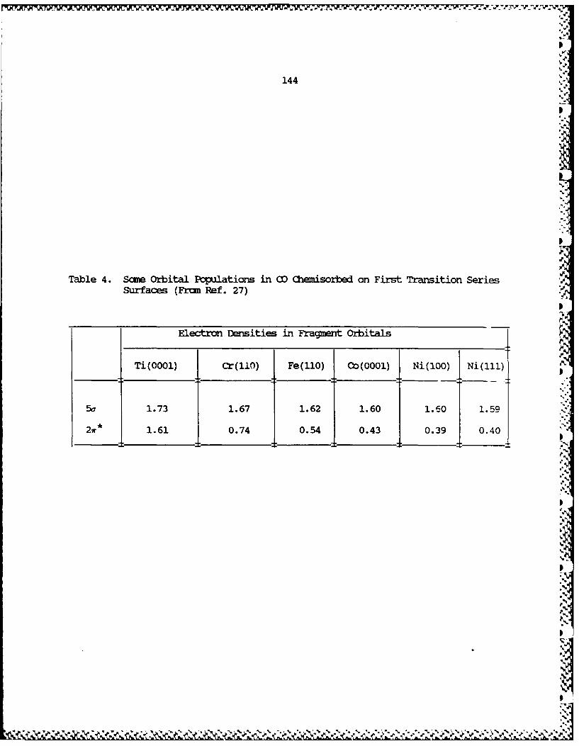
144p
Table 4. Some Orbital Populations in CO Chemisorbed on First Transition SeriesSurfaces (Frcm Ref. 27)
Electron Densities in Fragment Orbitals
Ti(0001) Cr(l0) Fe(I0) Co(0001) Ni(100) Ni(ll)
5a 1.73 1.67 1.62 1.60 1.60 J 1.5921r* 1.61 0.74 0.54 0.43 0.39 0.40
I...,%
JRp

V.,
145
The second case we studied is one specific reaction likely
to be important in the reductive oligomerization of carbon
monoxide over a heterogeneous catalyst, the Fischer-Tropsch AS
synthesis. The reaction is complicated and many mechanisms have
been suggested. In the one I think likely, the
"carbide/methylene" mechanism8 2 , one follows a sequence ofS
breaking up CO and H2 , hydrogenating the carbon to produce
methyl, methylene, methyne on the surface, followed by various
chain-forming associations of these and terminating reductive
eliminations. It is one of those terminal steps I want to
discuss here, a prototype associative coupling of two adsorbed
methyls to give ethane, 120.78
CH CH3 HSC-CH
It's simple to write down 120, but it hides a wonderful
variety of processes. These are schematically dissected in .5
121. First, given a surface and a coverdge, there is a preferred .
site which methyls occupy, perhaps an equilibrium between several
sites. Second, these methyls must migrate over the surface so as
to come near each other. A barrier, call it the "migration P
CH"-b CH I H iH d H v !!I '
-- - - +CH 3 -CH 3
121H . /7"7777 I//11 /////////i IIII
L/I/ll IIII /ll/J ///I II/II

146
Ienergy", may intervene. Third, one methyl coming into the
neighborhood of another may not be enough. It may have to come
really close, for instance, on-top of a neighboring metal atom.
That may cost energy, for one is creating locally a high-coverage
situation, one so high that it might normally be inaccessible.
one could call this a steric effect, but let's call it a
"proximity energy". Fourth, there is the activation energy to
the actual C-C bond formation, once the components are in place.
Let's call this the "coupling barrier". Fifth, there might be an
energy binding the product molecule to the surface. It is
unlikely to be important for ethane, but might be substantial for -
other molecules. It is artificial to dissect the reaction in
this way, nature does it all at once. But in our poor approach
to reality (and here we are thinking in terms of static energy
surfaces; we haven't even begun to do dynamics, to allow
molecules to move on these surfaces), we can think of the
components of the barrier impeding coupling: migration +
proximity + coupling + desorption energies.
To be specific, let's choose three dense surfaces:
Ti(OO0l), Cr(llO) and Cok'QO0l). The calculations we carried out
were for a 3-layer slab, and initially a coverage = 1/3. Three
binding sites that were considered were on-top or one-fold, 122,
bridging or two-fold, 123, cavping or three-fold, 124. The
preferred site for each metal is the on-top site, 122.78
Its
Ir o

147
The total binding energy is greater for Ti than Cr than Co.
125 is an interaction diagram for CH 3 chemisorption. The CH 3
frontier orbital, a carbon-based directed radical lobe, interacts
Tp
with metal s and z2 , much like the CO 5a. Some z2 states are
pushed up above the Fermi level, and this is one component of the
bonding. The other is an electron transfer factor. We started
with a neutral surface and a neutral methyl. But the methyl lobe
has room for 2 electrons. Metal electrons readily occupy it.
This provides an additional binding energy. And because the
Fermi levels increase to the left in the transition series, this
"ionic" component contributes more for Ti than for Co.7 8
In a sense, these binding energies of a single ligand are
not relevant to the estimation of relative coupling rates of two
ligands on different surfaces. But even they show the effect of
the Fermi level. A first step in coupling methyls is to consider
the migration barriers of isolated groups. This is done in 126.
I.
t1.

146
energy", may intervene. Third, one methyl coming into the
neighborhood of another may not be enough. It may have to come
really close, for instance, on-top of a neighboring metal atom.
That may cost energy, for one is creating locally a high-coverage
situation, one so nigh that it might normally be inaccessible.
One could call this a steric effect, but let's call it a
"proximity energy". Fourth, there is the activation energy to
the actual C-C bond formation, once the components are in place.
Let's call this the "coupling barrier". Fifth, there might be an
energy binding the product molecule to the surface. It is
unlikely to be important for ethane, but might be substantial for
other molecules. It is artificial to dissect the reaction in
this way, nature does it all at once. But in our poor approach
to reality (and here we are thinking in terms of static energy
surfaces; we haven't even begun to do dynamics, to allow
molecules to move on these surfaces), we can think of the
components of the barrier impeding coupling: migration +
proximity + coupling + desorption energies.
To be specific, let's choose three dense surfaces:
Ti(0001), Cr(ll0) and Co(0001). The calculations we carried out .
were for a 3-layer slab, and initially a coverage = 1/3. Three
binding sites that were considered were on-top or one-fold, 122,
bridging or two-fold, 123, capping or three-fold, 124. The
preferred site for each metal is the on-top site, 122.78
* 2-Sie

148
The relative energy zero in each case is the most stable on-top
geometry.
The implication of 126 is that for Co the preferred
migration itineraries are via bridged transition states, 127a,
for Ti via capping or hollow sites, 127b, whereas for Cr both are
r A A RA V .V
Relative E (eV):
Co 0.0 II 1.4
Cr 0.0 0.9 0.9 M7Ti 0.0 0.5 0.1
competitive. For the reasons behind the magnitudes of the
computed barriers, the reader is referred to our full paper.7 8 P
Could one design an experiment to probe these migration
alternatives? CH 3 has finally been observed on surfaces, but
remains a relatively uncommon surface species.5 4
If we bring two methyl groups to on-top sites on adjacent
metals, we see a splitting in the occupied CH3 states. This is a
typical two-orbital four-electron interaction, the way steric
effects manifest themselves in one-electron calculations. If we
compare the binding energy per methyl group in these proximate
structures to the same energy for low coverage isolated methyls,
we act the calculated proximity energies of 128. The

149
M M
Co 07 eVCr 0.5
Ti -0.1
destabilization increases with d electron count because some of4o
the d levels occupied carry CH3 lone pair contributions.
What happens when two CH 3 groups actually couple? The
reaction begins with both CH3 lone pairs nearly filled, i.e. a
representation near CH3 -. A new C-C a bond forms, and as usual,\F
we must consider a and a * combinations, nl±n 2. Both are filled
initially, but as the C-C bond forms, the a * combination will be
pushed up. Eventually, it will dump its electrons into the metal
d-band.
The actual evolution of the DOS and COOP curves allows one
to follow this process in detail. For instance, Fig. 38 shows
Figure 38
the contribution of the methyl n orbital, the radical lobe, to
the total DOS along a hypothetical coupling reaction coordinate.
Note the gradual formation of a two-peaked structure. COOP
'7irves show the lower peak is C-C bonding, the upper one C-C
antibonding. These are the c and* bonds of the ethane that is
. - € . -. .'... - , .' .". "'."'-,X". -" "-"'- v' " "' - '- v '",i ' '[%'k " '' ¢' ' €% f .

o¢( •0 t
all0' ,-- ............
0 0 0 CL)k 4-' Q~ C.
L A t/n 0
og l " -D 0
* .I- ) 4-)
cu) 0a
.............. ° °0f.4-)
o 0 C4 J .4-> cE
( 0 - ... .......... O -
0 -' IA 0) .-.
(U 0 (U
0 *b - ("
b ~4- 0
. b- 0 "C -
............
0< ....... 4-j -
0 4-) 0 0
-,, 0 4
I04(f 4-- QC Q --
L) 0 0 r_ 0
-- ' - -- ,'
b- )4-A
-) C0 0 A
> Ln0
0) L .
=) 0A * 4
0 0n
'(AO ii 0 C

150
being formed.
The total energy of the system increases along the reaction
path, as nl-n 2 becomes more antibonding. At the Fermi level,
there is a turning point in the total energy. a* = nl-n 2 is
vacated. The energy decreases, following a = nl+n 2. The
position of the Fermi level determines the turning point. So the
coupling activation energy is expected to be greater for Ti than
for Cr than for Co, because, as noted above, the Fermi level is
higher for the early transition metals, despite the lower d
electron count. The reader familiar with reductive eliminations
in organometallic chemistry will note essential
similarities.58 ,8 3 b We also mention here again the relationship
of our argument to the qualitative notions of Mango and
Schachtschneider on how coordinated metal atoms affect organic
reactions.57
The position of the Fermi level clearly is an important
factor in determining binding and reactivity on metal surfaces.
-II
p.!

151
Another Methodology and Some Credits
There have been an extraordinary number of theoretical
contributions to solid state and surface science. 8 4 These have
come from physicists and chemists, they have ranged from
semiempirical molecular orbital (MO) calculations to state-of-
the-art Hartree-Fock self-consistent-field + configuration
interaction (CI) and advanced density-functional procedures.
Some people have used atom and cluster models, some extended slab
or film models for surfaces. I will not discuss, I cannot
discuss all these contributions, even those relevant to the
systems I've mentioned, for the following reasons: (1) This is
not an exhaustive review of theoretical methods; (2) I'm lazy;
(3) The field is full of conflicting claims of validity for the
theoretical methods used. Such claims are of course typical of
the reality (rather than the ideology) of all science. But
theory especially is prone to them -- because theorists are
rarely dealing in the material, but mostly in the spiritual
world. That's inherent in the nature of answering the question,
the necessary and deep question, of "why?" and "how?". Basically
I'm not sure I can answer the question as to whether one or
another method is "better" than another, nor do I have the
courage to try.
Most of the theoretical methods at hand are just better ways
of solving the wave equation for the complex system at hand, not
necessarily leading to more chemical and physical understanding.

I
1524.
There is one exception, the complex of ideas on chemisorption
introduced and developed by Lundqvist, Norskov, Lang and their
coworkers. 8 5 This is a methodology rich in physical
understanding, and because of that and the fact that it provides
a different way of looking at barriers for chemisorption, I want
to mention the method explicitly here.
The methodology focuses, as many density-functional schemes
do, on the key role of the electron density. The Schr6dinger
equation is then solved self-consistently in the Kohn-Sham
scheme.8 6 Initial approaches dealt with a jellium-adatom system,
which would at first sight seem rather unchemical, lacking
microscopic detail. But there is much physics in such an
effective medium theory, and with time the atomic details at the
surface have come to be modeled with greater accuracy.
An example of the information the method yields is shown in
Fig. 39, the total energy and density of states profile for H2
dissociation on Mg(0001).8 7 There are physisorption (P),
Figure 39
molecular chemisorption (M), and dissociative chemisorption
wells, with barriers in between. The primary controlling factor
in molecular chemisorption is increasing occupation of H2 Cu
whose main density of states drops to the Fermi level and below
as the H2 nears the surface.p
5.

H2 on Mg (0001)
A
0
Recio ordnt
U-U
0 - ,p%
Recto Coodiat 0'
-.~0
Desty ofSae
Figure 39. Soecluae hrceitc"f 2o g00S fe eeec
32.~~~~~ ~ ~ ~ ~ To:shmtcptnileeg uv.P pyiopinmnmm
M =chmiore mlc e;B= hm iso daos n r rniinsae
fo c emiopi n discaton Botm/eeomn fteoeeetodensity~~~ ~ ~~ of sae atcranc rceiti ons ,adM orsodt
two ~ moeua hmsrt ons iffrn itne rmtesrae
The dashed line is the ou* dens~~~imvn tolwre rg as hed sci in
proceeds
-- I N
4-rl Ali iL \A'6

• n . . . 4..
153
In this and other studies by this method one sees molecular
levels, sometimes spread into bands, moving about in energy
space. But the motions seem to be different from those
calculated by the extended Huckel procedure. Fig. 18 showed for
H2 on Ni 8 8 some au* density coming below the Fermi level. But V
the main peak of au* was pushed up, as a simple interaction
diagram might suggest, but in apparent disagreement with the .
result of Fig. 39. Perhaps (I'm not sure) one way to reconcile
the two pictures is by recognizing that mine is not self-
consistent, does not account for proper screening of H2 as it
approaches the surface. It is possible that if self-consistency
or screening by electrons in the metal were included in the one-
electron formalism that the pictures could be reconciled. Also
there is less discrepancy between the two approaches than one
might imagine. In the reaction coordinate of Fig. 39 the H-H
bond is stretched along the progression P - A - M1 - M 2 - D - B.
au drops precipitously, in our calculations as well, as the H-H
bond is stretched.
The barriers to chemisorption in the work of Norskov et a18 7
come from the initial dominance of "kinetic-energy repulsion".
This is the Pauli effect at work, and I would like to draw a
correspondence between our four-electron repulsion and this
kinetic energy effect. The problem (as usual) is that different
models build in different parts of physical reality. It becomes
very difficult to compare them. The reason the effort is worth
,4'N . _

154
making is that the Lundqvist, Norskov, Lang model has proven
itself remarkably useful in revealing trends in chemisorption.
It is physically and chemically appealing.
There are some contributors to theoretical solid state
chemistry and surface science that I should like to mention
because of their special chemical orientation. One is Alfred P
Anderson, who has analyzed moit important catalytic reactions,
anticipating many of the results on surfaces presented in this
paper. 8 9 Evgeny Shustorovich and Roger C. Baetzold, working
separately and together, have both carried out detailed
calculations of surface reactions and come up with an important
perturbation-theory-based model for chemisorption phenomena.9 0
Christian Minot has worked out some interesting che:.isorption
problems.9 1 Myung-Hwan Whangbo's analyses of the bonding in low-
dimensional materials such as the niobium selenides, TTF-type
organic conductors and molybdenum bronzes, as well as his recent
studies of the high Tc superconductors, have contributed much to
our knowledge of the balance of delocalization and electron
repulsion in conducting solids. 7 ,8 Jeremy Burdett is responsible
for the first new ideas on what determines solid state structures
since the pioneering contributions of Pauling.5 ,6 His work is
consistently ingenious and innovative.9 3
Not the least reason I mention these people is pride: all
of them have at some time (prior to doing their important
independent work) visited my research group.
-, m -~.d ~ " ~ -~. J. ~ %'4~.%~

155
What's New in the Solid?
If all the bands in a crystal are narrow (as they are in
molecular and most extremely ionic solids), i.e. if there is
little overlap between repeating molecular units, then there is
no new bonding to speak of. But if at least some of the bands
are wide, then there is delocalization, new bonding, a molecular I
orbital picture is necessary. This is not to say that we cannot
recover, even in such a large dispersion, delocalized situation,
local bonding. The preceding sections have shown that we can see D
bonds. But there may be qualitatively new bonding schemes that
result from substantial delocalization. Recall in organic
chemistry the consequences of aromaticity, and in inorganicI
cluster chemistry of skeletal electron pair counting
algorithms.2 1
The language of orbital interactions, of perturbationI
theory, provides a tool that is applicable for the analysis of
these highly delocalized systems, just as it works for small,
discrete, molecules. For instance, take the question posed at
the end of a previous section. We have two isomeric two-
dimensional lattices 67, 68. Which will be a donor relative to
the other? And which will be most stable?
These lattices are built up from two elements B and X in
equal numbers, occupying two sublattices, I and II in 129. The
elements are of unequal electronegativity, in the general case.
In ThCr2 Si2 one is a transition metal, the othe: a main-group
~ 4' |

156156 -~---jSite a
I
0* Site I
~4 '~ ~-Site U
a b129
element, in CaBe 2Ge 2 each a main-group element. Let's take, for
purposes of discussion, the latter case as a model and write an
interaction diagram for what happens locally, 130.
The diagram has been drawn in such a way that the more
electronegative element is X. No implication as to band width is
yet made -- the orbital blocks are just that, blocks, indicating
the rough position of the levels. The lower block of levels is
obviously derived from or localized in the orbitals of the more
electronegative (here X) element. The band filling is actually
2-.
appropriate to the CaBe2Ge2 structure, i.e. Be2Ge22- or BeGe-
or 7 electrons per two main-group atoms.
The orbitals develop into bands. The width of the bands
depends on the inter-unit-cell overlap. The site II atoms are
much farther apart from each other than the site I atoms (recall
here the short metal-metal contacts in the ThCr2Si 2 structure).
V. V.

157
We can say that sublattice I is more dispersive than sublattice
II. The orbitals of atoms placed in sublattice I will form wider
bands than those in sublattice II.
Now we have two choices: the more electronegative atoms can
enter the less dispersive sites (lattice II) or the more
dispersive sites (lattice I). The consequences are shown in 131 !
and 132.
131 i3Z
Which layer will be most stable and which will have the
higher Fermi level depends on the electron filling. For a case
sich as CaBe 2Ge2 , or in general where the lower band is more than
half-filled, the more electronegative atom will prefer the less
dispersive site 131 and that layer will have a higher I.P., be a.x
poorer donor. %I
The stability conclusion bears a little elaboration. It is
based on the same "overlap repulsion" argument that was behind
the asymmetric splitting of hydrogen chain bands, Fig. 1. When
orbitals interact, the antibonding combinations are more
antibonding than the bonding ones are bonding. Filling
antibonding combinations, filling the tops of widely dispersed IIl
.5

DI
158
bands, is costly in energy. Conclusions on stability, as is the
case in molecular chemistry, depend strongly on the electron
count. In this particular case if the lower band were less than
half-filled, the conclusion would be reversed, the more
electronegative element should prefer the more dispersive site.
For ThCr 2Si2 AB 2 X2 structures the conclusion we reach, that
the more electronegative element should enter the less dispersivesite, implies that for most cases the main-group X component will
prefer the less dispersive, square pyramidal, sublattice II
positions. In CaBe2 Ge2 , Ge is more electronegative than Be.
That means the layer in which the Ge enter the more dispersive
sites (the bottom layer in 66) should be a donor relative to the
upper layer.
A reasonable question to ask is the following. If one layer
(the acceptor layer) in CaBe2Ge 2 is more stable than the other,
the donor layer, why does the CaBe 2Ge2 structure form at all?
Why doesn't it go into a ThCr 2Si 2 structure based on the acceptor
layer alone? The answer lies in the balance of covalent andI
dative interactions; for some elements the binding energy gained
in donor-acceptor interlaver interactions overcomes the inherent
stability of one layer isolated.39c
IAt times the perturbation introduced by delocalization may
be strong enough to upset the local, more "chemical" bonding
schemes. Let me sketch two examples here.I
I

159
Marcasites and arsenopyrites are a common structural choice
for MA 2 compounds, where M is a late transition metal, A a group
15 or 16 element. The structure, 133, is related to the rutile
one, in that one can easily perceive in the structure the
octahedral coordination of the metal, and one-dimensional chains
of edge-sharing octahedra. The ligands are now interacting,
however; not 2(02-) as in rutile, but S22- or P2 4- diatomic units
in the marcasites.9 2
Low dimensionality characterizes another set of MS 2
sublattices, now in ternary structures of the type of KFeS 2 or
Na3 Fe2S4 .9 3 ,9 4 In these molecules one finds one-dimensional MS2
chains, consisting of edge-sharing tetrahedra, 134.
IS4-
.I
r /s _ .s s\ ,, I
\ ... /- .. __/ ..... , . -. / "
-S

160
In both of these structural types, characterized by their
simplicity, the metal-metal separations are in the range (2.6-3.1
A) where reasonable men or women might disagree whether there is
much metal-metal bonding. Cases with bridging ligands are ones
in which real metal-metal bonding is particularly difficult to
sort out from bonding through the bridge. Certainly the metal-
metal bonding doesn't look to be very strong, if it's there at
all. So a chemist would start out from the local metal site
environment, which is strikingly simple.
One would then predict a three below two orbital splitting
at each metal in the octahedral marcasites and a two below three
splitting in the tetrahedral MS2 chains. The magic electron
counts for a closed-shell low-spin structure should be then d6
for the octahedral 133, d4 for the tetrahedral 134. Forming the
one-dimensional chains and then the three-dimensional structure
will introduce some dispersion into these bands, one might
reason. But not much -- appropriate electron counts for
semiconducting or non-magnetic behavior should remain d6 for 133
and d4 for 134.
The experimental facts are as follows: the d6 marcasites
and arsenopyrites are semiconducting, but, surprisingly, so are
the d4 ones. Most of the AMS2 structures synthesized to date
feature the metal atom in configurations between d5 and d6 .5 .
The measured magnetic moments are anomalously low.

161
I
When calculations on these chains are carried out one finds,
to one's initial surprise, that the octahedral marcasite
structure has a band gap at d4 as well as d6 , and that the
tetrahedral chain has a band gap at d5 "5 and not d4 . It seems
that local crystal field considerations don't work. What in fact
happens (and here the reader is referred to the detailed
explanation in our papers9 2 ,9 4 ) is that the local field is a good
starting point, but that further delocalizing interactions (and
these are ligand-ligand and metal-ligand, and not so much metal-
metal in the distance range considered) must be taken into
account. The extended interactions modify the magic or gap
electron counts that might be expected from just looking at the
metal site symmetry.
In a preceding section, I outlined the orbital interactions
that are operative in the solid state. These were the same ones
as those that govern molecular geometries and reactivity. But
there were some interesting differences, a consequence of one of
the interacting components, the surface, having a continuum of
levels available at the Fermi level. This provided a way to turn
strong four and zero electron two-orbital interactions into
bonding ones. As a corrolary, there are shifts around the Fermi
level which have bonding consequences. Let's look at this new
aspect in detail on an example we had mentioned before, acetylene
chemisorbed in low coverage in a parallel, two-fold bridging mode
29ion Pt(ll), 135.29 1
IN%
AS

1621621
The most important two-electron bonding interactions that
take place are between two of the acetylene w orbitals, wa and
a* (see 136) and the d band. ra and Ira* "point" toward the
surface, have greater overlap with metal overlaps, and they
interact preferentially with different parts of the band, picking "
out those metal surface orbitals which have similar nodal
patterns as the adsorbate. 137 shows this -- in the "parallel
bridging" geometry at hand the w. orbital interacts better with
the bottom of the surface z2 band and the wr* with the top of
that band.
I (a
(Pt, Pta
Both of these interactions are primarily of type( and 0
(see 54 or 59), four-electron repulsive or two-electron
attractive interactions. Actually, the energetic and bonding
consequences are a little complicated: the z2-ora interaction
would be destabilizing if the antibonding component of this

163
interaction remained filled, below the Fermi level. In fact,
many z 2 -7r antibonding states are pushed above the Fermi level,
vacated. This converts a destabilizing, four-electron
interacti-n into a stabilizing two-electron one.
A counterpart to this interaction is®. Normally we would
noE worry about zero-electron interactions, because there is not
"power" in them if there are no electrons. However, in the case
of a metal with a continuous band of states, some of these levels
-- these are bonding combinations of ir* with the top of the z2
band, as indicated in 137 -- come below the Fermi level and are
occupied. Therefore they also contribute to bonding the
adsorbate to the surface.
It should be noted that a consequence of all of these
interactions is not only strengthening of metal-acetylene
bonding, but also a weakening of bonding within the acetylene and
within the metal. Interaction means delocalization which in turn
implies charge transfer. Interactions and® , operate to
depopulate r., populate x , both actions weakening the acetylene
r bond. Removing electrons from the 'bottom of the z2 band,
filling better the top of that bond, both result in a weakening
of the Pt-Pt bond.
Interaction @, peculiar to the solid, is a reorganization
of the states around the Fermi level as a consequence of primary
interactionsQ , ©, , ®. Consider, for instance, the levels
that are pushed up above the Fermi level as a result of

164
interactionQ, the four-electron repulsion. One way to think
about this is the following: the electrons do not, in fact, go
up past the Fermi level (which remains approximately constant),
but are dumped at the Fermi level into levels somewhere in the
solid. This is shown schematically in 138.
139
But where is "somewhere"? The electrons that come in come
largely from regions that are not directly involved in the
bonding with the adsorbate. In the case at hand they may come
from Pt bulk levels, from Pt surface atoms not involved with the
acetylene, even from the Pt atoms binding the acetylene, but from
orbitals of these atoms not used in that binding. While the
metal surface is a nice reservoir of such electrons, these
electrons are not innocent of bonding. They are near the top of
their respective band, and as such are metal-metal antibonding.
Thus interaction @ weakens bonding in the surface. Together with
the aforementioned electron transfer effects of interactionsQ,
o,., and it is responsible for adsorbate-induced surface
reconstruction.
1I

165 !!
I
In general, as I already outlined in a previous section,
non-dissociative chemisorption is a delicate balance of the very
same interactions, which weaken bonds in the adsorbed molecule
and in the surface. Dissociative chemisorption and surface
reconstruction are just two extremes of one and the same
phenomenon.
So what's new in the solid? My straw-man physicist friend,
thinking of superconductivity, charge and spin density waves,
heavy fermions, solitons, nonlinear optical phenomena,I
ferromagnetism in its various guises -- all the fascinating
things of interest to him and that I've neglected - he might say
"Everything". An exaggeration of what I've said in this paper isI
"Not much". There are interesting, novel, consequences of
delocalization and wide-band formation, but even these can be
analyzed in the language of orbital interactions.
It would not surprise anyone if the truth were somewhere in
between. It is certainly true that I've omitted, by and large,
the origins of most of the physical properties of the solid,
especially those such as superconductivity and ferromagnetism, 1
which are peculiar to that state of matter. Chemists will have
to learn much more solid state physics than I've tried to teach
here if they are to understand these observables, and they must R
understand them if they are to make rational syntheses.
What I have tried to do in this book and the published
papers behind it is to move simultaneously in two directions -- I
SI

II
166
to form a link between chemistry and physics by introducing
simple band structure perspectives into chemical thinking about
surfaces. And I have tried to interpret these delocalized band
structures from a very chemical point of view -- via frontier
orbital considerations based on interaction diagrams.
Ultimately, the treatment of electronic structure in
extended systems is no more complicated (nor is it less so) than
in discrete molecules. The bridge to local chemical action
advocated here is through decompositions of the DOS and the
Crystal Orbital Overlap Population (COOP) curves. These deal
with the fundamental questions: Where are the electrons? Where
can I find the bonds?
With these tools in hand, one can construct interaction
diagrams for surface reactions, as one does for discrete
molecules. One can also build the electronic structure of
complicated three-dimensional solids from their sublattices.
Many similarities between molecules and extended structures
emerge. And some novel effects, the result of extensive
delocalization.
I have concentrated on the most chemical notion of all --
the solid is a molecule, a big one, to be sure, but just a
molecule. Let's try to extract from the perforce delocalized
picture of Bloch functions the chemical essence, the bonds that
determine the structure and reactivity of this large molecule.
The bonds must be there.
V. ~ F" ',~, ~., W.%d ~ ~ ~%

167
References
1. There is no single, comprehensive textbook of solid
state chemistry. Perhaps this reflects the diversity
of the field, the way it has grown from many different
subdisciplines of chemistry, physics and engineering.
Among the books I would recommend are
(a) Wells, A.F. "Structural Inorganic Chemistry", 5th edn.
Oxford Univ. Press, Oxford, 1984.
(b) Krebs, M. "Fundamentals of Inorganic Crystal
Chemistry", McGraw Hill, 1968.
(c) West, A.R. "Solid State Chemistry and its
Applications", John Wiley and Sons, New York 1984.
(d) O'Keeffe, M.; Navrotsky, A.; Eds. "Structure and
Bonding in Crystals", Volumes I and II, Academic Press,
New York 1981.
(e) Cox, P.A. "The Electronic Structure and Chemistry of
Solids", Oxford University Press, Oxford, 1981.
2. For highly readable introduction to surface chemistry,
see Somorjai, G. A. "Chemistry in Two Dimensions:
Surfaces", Cornell University Press, Ithaca (1981).
See also Rhodin, T. N., Ertl, G. Eds., "The Nature of
the Surface Chemical Bond", North-Holland, Amsterdam,
1979.
3. (a) Zintl, E.; Woltersdorf, G. Z. Elektrochem., 1935, 41,
876; Zintl, E.; AnQew. Chem. 1939, _j, 52.

168 V
(b) Klemm,W.; Busmann, E.; Z. Anorq. Allcrem. Chem., 1963,
319, 297; Klemm, W. Proc. Chem. Soc. London, 1958, 329.
(c) Schafer, H.; Eisenmann, B.; Mller, W. Ancqew. Chem.,
1973, 85, 742; Angew Chem. Int. Ed., 1973, 12, 694.
(d) Schafer, H. Ann. Rev. Mater. Sci., 1985, 15, 1 and
references therein.
4. Hoffmann, R. J. Chem. Phys., 1963, 39, 1397; Hoffmann
R.; Lipscomb, W. N. ibid, 1962, 36, 2179; 1982, 37,
2872. The extended Huckel method was devised in the
exciting atmosphere of the Lipscomb laboratory; L. L.
Lohr played an essential part in its formulation. The
first Cornell implementation to an extended material
was made by M.-H. Whangbo; Whangbo, M.-H.; Hoffmann, R.
J. Amer. Chem. Soc., 1978, 100, 6093; Whangbo, M.-H.;
Hoffmann, R.; Woodward, R. B. Proc. Roy. Soc., 1979,
A366, 23.
5. (a) Burdett, J. K. Nature, 1979, 279, 121.
(b) Burdett, J. K. in Ref. id.
(c) Burdett, J. K. Accts, Chem. Res. 1982, 15, 34 (1982),
and references therein.
6. Burdett, J. K. Progr. Sol. St. Chem., 1984, 15, 173.
7. Whangbo, M.-H. in "Extended Linear Chain Compounds",
ed. Miller, J. S. Plenum Press, New York, 1982, p. 127.
8. Whangbo, M.-H. in "Crystal Chemistry and Properties of '.
Materials with Quasi-One Dimensional Structures:, ed.
Rouxel, J.; Reidel, Dordrecht, 1986, p. 27. .
X.

169
9. The modern classic solid state physics text is by
Ashcroft, N. W. and Mermin, N. D. "Solid State
Physics", Holt, Rinehart and Winston, New York, 1976.
Three other introductions to the tield, ones which I
think are pedagogically effective and accessible to
chemists are: Harrison, W. A. "Solid State Theory",
Dover, New York, 1980. Harrison, W. A.: "Electronic
Structure and the Properties of Solids", Freeman, San
Francisco, 1980; Altman, S. L. "Band Theory of Metals",
Pergamon Press, New York, 1970.
10. Excellent introductions to this subject, written in the
spirit of this book, and with a chemical audience in
mind, are to be found in Ref. 6, 8, in the book by P.
A. Cox in Ref. 1, and in the article by Kertesz, M.
Int. Rev. Phys. Chem., 1985, 4, 125.
11. Albright, T. A. ; Burdett, J. K., Whangbo, M. H.
"Orbital Interactions in Chemistry", New York, Wiley-
Interscience, 1985, Chapter 20.
12. For a review of this fascinating class of materials see
Williams, J. R. Adv. Inorg. Chem. Radiochem., 1983, 26,
235.
13. Cotton, F. A.; Walton, R. A. "Multiple Bonds Between
Metal Atoms" John Wiley and Sons, New York, 1982, and
references therein.
14. For more information on the platinocyanides, see Ref.
7, 8 and 12.

170
15. For this task, and for band structure calculation in
general, a chemist needs to learn group theory in the
solid state. For a lucid introduction, see Tinkham, M.
J.: "Group Theory and Quantum Mechanics," McGraw-Hill,
New York, 1964; Burns G.; Glazer A. M. "Space Groups
for Solid State Scientists," Academic Press, New York,
1978; Madelung, 0. "Introduction to Solid State
Theory," Springer Verlag, Berlin, 1978.
16. Tremel, W.; Hoffmann, R. J. Amer. Chem. Soc., 1987,
.109, 124; Inorg. Chem., 1987, _U, 118; Keszler, D.;
Hoffmann, R. J. Amer. Chem. Soc., 1987, 109, 118.
17. Zonnevylle, M.C.; Hoffmann, R. Lancnmuir, 1987, 3, 452.
18. Trinquier, G.; Hoffmann, R. J. Phys. Chem., 1984, 88,
6696.
19. Li, J.; Hoffmann, R. Z. Naturforsch., 1986, 41b, 1399.
20. The following references are just ways in to the vastC.
literature of reconstruction: Kleinle, G.; Penka, V.;
Behm, R. J. ; Ertl, G.; Moritz, W. Phys. Rev. Lett.,
1987, 58, 148. Daum, W.; Lehwald, S.; Ibach, H. Surf.
Sci., 1986, 178, 528; Van Hove, M. A.; Koestner, R. J.;
Stair, P.C.; Biberian, J.P,; Kesmodel, L.L.; Bartos,
I.; Somorjai, G. A. Surf. Sci., 1981, 103, Inglesfield,
J. E.; Progr. Surf. Sci., 1985, 20, 105; King, D. A.
Phys. Scripta, 1983, 4, 34; Chan, C.-M.; Van Hove, M.
A. Surf. Sci., 1986, 171, 226; Christmann, K. Z. Phys.
Chem., 1987, 154, 145.

171
21. (a) Wade, K. Chem. Commun., 1971, 792; InorQ. Nucl. Lett.,
1972, 8, 559; "Electron Deficient Compounds", Nelson,
London, 1971.
(b) Mingos, D.M.P. Nature (London) Phys. Sci., 1972, 236,
99.
22. It should be clear that this is just one possible
methodology. Many other theoretical chemists and
physicists prefer a cluster approach, i.e. a finite
group of metal atoms and single adsorbate. The local
chemical action is then emphasized, though one has to
worry about how the cluster is terminated, or what the
end effects are. More recently people have begun to
consider embeddings of clusters in extended structures.
23. For more on the electronic structure of rutile and
related compounds see Burdett, J. K.; Hughbanks, T.
Inora. Chem., 1985, 24, 1741; Burdett, J. K. Inorg.
Chem., 1985, 24, 2244; Mattheiss, L. F. Phys. Rev.,
1976, B13, 2433.
24. Some leading references to early band structure
calculations are the following:
(a) Mattheiss, L. F. Phys. Rev. Lett., 1987, 58, 1028.
(b) Yu, J. J.; Freeman, A. J.; Xu, J.-H. Phys. Rev. Lett.,
1987, 58, 1035; Massidda, S.; Yu, J.; Freeman, A. J.;
Koelling, D. D. Phys. Lett., 1987, A122, 198.
(c) Whangbo, M.-H.; Evain, M.; Beno, M. A.; Williams, J. M.
Inorg. Chem, 1987, 26, 1829; ibid, 1987, 26, 1831;

172
Whangbo, M.-H.; Evain, M.; Beno, M. A.; Geiser, U.;
Williams, J. M., jjd, 1987, 2_6, 2566.
(d) Fujiwara, R.; Hatsugai, Y. Japanese J. Appl. Phys.,
1987, 26, L716.
25. Goodenough, J. B. "Magnetism and the Chemical Bond",
Krieger, New York, 1976.
26. Mulliken, R. S. J. Chem. Phys., 1955, 23, 1833, 2343.
27. For further details see Sung, S.; Hoffmann R. J. Amer.
Chem Soc., 1985, 107, 578.
28. (a) For discussion of other calculations of CO on Ni
surfaces see Kasowski, R. V.; Rhodin, T.; Tsai, M.-H.
Ayq1. Phys., 1986, A41, 61, and references therein.
(b) Avouris, Ph.; Bagus, P. S.; Nelin, C. J. J. Electron.
Spectr. Rel. Phen., 1986, 38, 269 have stressed the
importance of this phenomenon. We disagree on its
magnitude, in that we find Px,y mixing into the main
2w* density at -7 eV small. The COOP curve, to be
shown later in Fig. 24, indicates that the density in
this peak is Ni-C antibonding.
29. For further details see Silvestre, J.; Hoffmann, R.
* Langmuir, 1985, 1, 621.
30. See Saillard, J.-Y.; Hoffmann, R. J. Amer. Chem Soc.,
1984, 106, 2006 for further details.
31. (a) Shustorovich, E. J. Phys. Chem., 1983, 87, 14.
(b) Shustorovich, E. Surf. Sci. Reports, 1986, 6, 1.
-.-. .. N 6 O ~ * .~u~

173
32. Shustorovich, E.; Baetzold, R. C. Science, 1985, 227,
876.
33. There is actually some disagreement in the literature
on the relative role of C-H and H-H a and a* levels in
interactions with metal surfaces. A. B. Anderson finds
a donation playing the major role. See e.g. Anderson,
A. B. J. Amer. Chem Soc., 1977, 99, 696 and subsequent
papers.
34. COOP was introduced for extended systems in papers by
(a) Hughbanks, R.; Hoffmann, R. J. Amer. Chem. Soc., 1983,
105, 3528.
(b) Wijeyesekera, S. D.; Hoffmann, R. Orcanometal., 1984,
3, 949.
(c) Kertesz, M.; Hoffmann, R. J. Amer. Chem Soc., 1984.
106. 3453.
(d) An analogous index in the HUckel model, a bond order
density, was introduced earlier by van Doorn, W.;
Koutecky, J. Int. J. Quantum Chem., 1977, 12, Suppl. 2,
13.
35. This is from an extended Huckel calculation (Ref. 30).
For better estimates see Ref. 40.
36. For some references to this story, see footnote 5 in
Ref. 29. An important early LEED analysis here was by
Kesmodel, L. L.; Dubois, L. H.; Somorjai, G. A. J.
Chem. Phys., 1979, 70, 2180.
S.

174
37. Pearson, W. B. J. Sol. State Chem., 1985, 56, 278 and
references therein.
38. Mewis, A. Z. Naturforsch., 1980, 35b, 141.
39. (a) Zheng, C.; Hoffmann, R. J. Phys. Chem., 1985, 89, 4175.
(b) Zheng, C.; Hoffmann, R, Z. Naturforsch., 1986, 41b,
292.
(c) Zheng, C.; Hoffmann, R. J. Amer. Chem. Soc., 1986, 108,
3078.
40. Andersen, 0. K. in "The Electronic Structure of Complex
Systems", ed. Phariseau, P.; Temmerman, W. M.; Plenum
Press, New York, 1984; Andersen, 0. K. in "Highlights
of Condensed Matter Physics", ed. Bassani, F.; Fumi,
F.; Tossi, M. P.; North-Holland, New York, 1985.
See also Varma, C.M.; Wilson, A.J. Phys. Rev. 1980,
B22, 3795.
41. (a) The frontier orbital concept is a torrent into which
flowed many streams. The ideas of Fukui were a crucial
early contribution (the relevant papers are cited by
Fukui, K. Science, 1982, 218, 747) as was the
perturbation theory based PMO approach of Dewar (see
Dewar, M.J.S. "The Molecular Orbital Theory of Organic
Chemistry." McGraw-Hill, New York 1969 for the
original references). The work of Salem was important
(see Jorgensen, W.L., Salem, L. "The Organic Chemist's
Book of Orbitals", Academic Press, New York, 1973, for
references and a model portrayal, in the discussion
-)~-~.

175
preceding the drawings, of the way of thinking which my
coworkers and I also espoused). The Albright, Burdett
and Whangbo text (Ref. 11) carries through this
philosophy for inorganic systems, and is also an
excellent source of references.
(b) For surfaces, the frontier orbital approach is really
there in the pioneering work of Blyholder, G., J. Phys.
Chem., 1964, 68, 2772. In our work in the surface
field, we first used this way of thinking in Ref. 30, a
side-by-side analysis of molecular and surface H-H and
C-H activation.
. 42. Murrell, J. N.; Randic, M.; Williams, D. R. Proc. Roy.
Soc., 1965, A284, 566; Devaquet, A.; Salem, L. J. Amer.
Chem. Soc., 1969, 91, 379; Fukui, X; Fujimoto, H. Bull
Chem. Soc. Jpn., 1968, 41, 1984; Baba, M.; Suzuki, S;
Takemura, T. J. Chem. Phys., 1969, 50, 2078; Whangbo,
* M.-H.; Wolfe, S. Can. J. Chem., 1976, 54, 949;
Morokuma, K. J. Chem. Phys., 1971, 55, 1236 is a
sampling of these.
43. See for instance Kang, A. B.; Anderson A. B. Surf.
Sci., 1985, 155, 639.
44. Gadzuk, J. W., Surf. Sci., 1974, 43, 44.
45. Grimley, T. B. J. Vac. Sci Technol., 1971, 8, 31; in
"Adsorption-Desorption Phenomena", ed. Ricca, F. 1972,
Academic Press, New York, p. 215 and subsequent papers.
See also Thorpe, B. J. Surf. Sci. 1972, 33, 306.
'S£
.|

176
46. van Santen, R. A. Proc. 8th Congr. Catal., Springer
Verlag, Berlin, 1984, Vol. IV, p. 97; Far. Symp. Chem.
Soc., 1986, 21,
47. Salem, L.; Leforestier, C. Surf. Sci., 1979, 82, 390;
Salem, L.; Elliot, R. J. Mol. Struct. Theochem., 1983,
93, 75; Salem, L. J. Phys. Chem., 1985, 89, 5576;
Salem. L.; Lefebvre, R. Chem. Phys. Lett., 1985, 122,
342.
48. (a) Banholzer, W. F.; Park, Y. 0.; Mak, K. M.; Masel, R. I.
Surf. Sci., 1983, 128, 176; Masel, R. I., to be
published.
49. See Elian, M.; Hoffmann, R. Inorg. Chem., 1975, 14,
1058.
50. The effect mentioned here has also been noted by Raatz,
R.; Salahub, D. R. Surf. Sci., 1984, 146, L609;
Salahub, D. R.; Raatz, F. Int. J. Quantum Chem., 1984,
Symp. No. 18, 173; Andzelm, J.; Salahub, D. R. Int. J.
Quantum Chem., 1986, 29, 1091.
51. Dewar, M.J.S. Bull Soc. Chim Fr., 1951, I8, C71; Chatt,
J.; Duncanson, L. A. J. Chem. Soc., 1953, 2939.
52. Muetterties, E. L. Chem. Soc. Revs., 1982, 11, 283;
Angew. Chem. Int. Ed. Enql., 1978, 17, 545;
Muetterties, E. L. ; Rhodin, T. N. Chem. Revs., 1979,
79, 91.

I177
53. Garzunkel, E. L.; Minot, C.; Gavezzotti, A.; Simonetta,
M. Surf. Sci., 1986, 167, 177; Garfunkel, E. L.; Feng,
X. Surf. Sci., 1986, 176, 445; Minot, C.; Bigot, B.;
Hariti, A. Nouv. J. Chim., 1986, i0, 461. See also
Ref. 50 and Shustorovich, E. M. Surf. Sci., 1985, 150,
L115.
54. Tang, S. L.; Lee, M. B.; Beckerle, J. D.; Hines, M. A.;
Ceyer, S. T. J. Chem. Phys., 1985, 32, 2826; Tang, S.
L.; Beckerle, J. D.; Lee, M. B.; Ceyer, S. T. ibid.,I
1986, 84, 6488. See also Lo, T.-C.; Ehrlich, B. Surf.
Sci., 1987, 179, L19; Steinruck, H.-P.; Hamza, A. V.;
Madix, R. J. Surf. Sci., 1986, 173, L571; Hamza, A. V.;
Steinruck, H.-P.; Madix, R. J. J. Chem. Phys., 1987,
86, 6506 and references in these.
55. Several such minima have been computed in the
interaction of atomic and molecular adsorbates with Ni
clusters: P.E.M. Siegbahn, private communication.
56. Kang and Anderson in Ref. 43 and papers cited there.
57. Mango, F. D.; Schachtschneider, J. H. J. Amer. Chem.
Soc., 1967, 89, 2848; Mango, F. D. Coord. Chem. Revs.,
1978, 15, 109.
58. Hoffmann, R. in "IUPAC. Frontiers of Chemistry", ed.
Laidler, K. J. Pergamon Press, Oxford 1982; Tatsumi,
K.; Hoffmann R.; Yamamoto, A.; Stille, J. K. Bull.
Chem. Soc. Jpn., 1981, 54, 1857 and references therein.
59. See Ref. 29 for detailed discussion of this phenomenon.
S
-"X %5.~ ~~~~ ~~~ v&.5.-;% V, .~% 'S N'.

-V -,r 4,. 4 V. -Wy W 7W - . W . - .
I.
178
60. Anderson, A. B.; Mehandru, S. P. Surf. Sci., 1984, 136,
398; Kang, D. B.; Anderson, A. B. ibid., 1986, 165,
221.
61. For a review see Chevrel, R. in "Superconductor
Materials Science: Metallurgy, Fabrication, and
Applications", ed. Foner, S.; Schwartz, B. B.; PlenumI
Press, New York, 1981, Chap. 10.
62. Lin, J.-H.; Burdett, J. K. InorQ. Chem., 1982, 5, 21.
63. Hughbanks, T.; Hoffmann, R. J. Amer. Chem. Soc., 1983,
105, 1150. :.
64. See also Andersen, O.K.; Klose, W.; Nohl, H. Phys.
Rev., 1977, B17, 1760; Nohl, H.; Klose, W.; Andersen, .
O.K. in "Superconductivity in Ternary Compounds" ed.
Fisher, 0.; Maple, M.B., Springer Verlag, 1981, Chap.
6; Bullett, D.W. Phys. Rev. Lett., 1980, 44, 178.
65. See. Ref. 39c and papers cited therein.
66. This drawing is taken from Ref. 11. Excellent
descriptions of the folding back process and its
importance are to be found in Ref. 6 and 8.
67. The original reference is Jahn, H.A.; Teller, E. Proc
Roy. Soc., 1937, A161, 220. A discussion of the
utility of this theorem in deriving molecular
geometries is given by Burdett, J.K. "Molecular
Shapes", Wiley, New York, 1960; Burdett, J. K. InorQ.
Chem., 1981, 20, 1959 and references cited therein.

179
See also Ref. 6, 8 and Pearson, R. G. "Symmetry Rules
for Chemical Reactions", Wiley, New York, 1976. The
first application of the Jahn-Teller argument to
stereochemical problems, and, incidentally, to
condensed phases, was made by Dunitz, J.D.; Orgel, L.E.
J. Phys. Chem. Sol., 1957, 20, 318; Adv. InorQ. Chem.
Radiochem., 1960, 2, 1; Orgel, L.E.; Dunitz, J.D.
Nature, 1957, 179, 462.
68. Peierls, R.E. "Quantum Theory of Solids", Oxford
University Press, Oxford, 1972.
69. Longuet-Higgins, H.C.; Salem, L. Proc. Roy. Soc., 1959,
A251, 172.
70. For leading references see the review by Kertesz, M.
Adv. Ouant. Chem., 1982, 15, 161.
71. Pearson, W.B. Z. Kristalloqr., 1985, 171, 23 and
references therein.
72. Hulliger, F.; Schmelczer, R.; Schwarzenbach, D. J. Sol.
State Chem., 1977, 21, 371.
73. Schmelczer, R.; Schwarzenbach, D.; Hulliger, F. Z.
Naturforsch., 1981, 36b, 463 and references therein.
74. (a) Burdett, J.K.; Haaland, P.; McLarnan, T.J. J. Chem.
Phvs., 1981, 75, 5774.
(b) Burdett, J.K.; Lee, S. J. Amer. Chem. Soc., 1983, 105,
1079.
(c) Burdett, J.K.; McLarnan, T.J. J. Chem. Phys., 1981, 75,
5764.
%.

180 .,
(d) Littlewood, P.B. CRC Critical Reviews in Sol. State and
Mat. Sci., 1984, 11~, 229.
75. Tremel, W.; Hoffmann, R. J. Am. Chem. Soc., 1986, 108,
5174, and references cited therein; Silvestre, J.;
Tremel, W.; Hoffmann, R. J. Less Common Met., 1986,
116~, 113.
76. Franzen, H.F.; Burger, T.J. J. Chem. Phys., 1968, 49,
2268; Franzen, H.F.; Wiegers, G.A. J. Sol. State Chem.,
1975, 13., 114.
77. See Ref. 75 and Kertesz, M.; Hoffmann, R. J. Amer.Chem Soc, 184, 06, 453
78. Zheng. C.; Apeloig, Y.; Hoffmann, R. J. Amer. Chem.
Soc.,, 1988, 110Q,
79. Broddn, G.; Rhodin, T.N.; Brucker, C.; Benbow, H.;
Hurych, Z. Surf. Sci., 1976, 59, 593; Engel, T.; Ertl,
G. Adv. Catal., 1979, 28, 1.
80. Shinn, N.D.; Madey, R.E. Phys. Rev. Lett., 1984, 53,
2481; J. Chem. Phvs., 1985, 83, 5928; Phys. Rev., 1986,
B33, 1464; Benndorf, C.; Kruger, B.; Thieme, F. Surf.r
ScL., 1985, JU L675. On Pt3Ti a similar assignment
has been made: Bardi, U.; Dahlgren, D.; Ross, H. J.
Catal., 1986, 100, 196. Also for CN on Cu and Pd
surfaces: Kordesch, M.E.; Stenzel, W.; Conrad, H. J.
Electr. Spectr. Rel. Phen., 1986, 38, 89; Somers, J.;
Kordesch, M.E.; Lindner, Th.; Conrad, H.; Bradshaw,
A.M.; Williams, G.P. Surf. Sci., 1987, 188, L693.

181
81. Mehandru, Z.P.; Anderson, A.B. Surf. Sci., 1986, 169,
L281; Mehandru, S.P.; Anderson, A.B.; Ross, P.N. J.Catal., 1986, 10_0, 210.
82. or a recent review, see Anderson, R.B. "The Fischer-
Tropsch Synthesis", Academic Press, New York, 1984.
83. (a) See, however, Baetzold, R. J. Amer. Chem. Soc., 1983,
i05, 4271 and Wittrig, T.S., Szoromi, P.D.; Weinberg,
W.M. J. Chem. Phys., 1982, 76, 3305.
(b) See also Lichtenberger, D.L.; Kellogg, G.E. Accounts
Chem. Res., 1987, 20, 379 and Wilker, C.N.; Hoffmann,
R.; Eisenstein, 0. Nouv. J. Chim., 1983, 7, 535.
84. Reviews of some of the theoretical work on surfaces may
be found in Gavezzotti, A.; Simonetta, M. Adv. Quantum
Chem., 1980, 12, 103; Messmer, R.P. in Semiempirical
Methods in Electronic Structure Calculations, Part B:
Applications", Ed. Segal, G.A. Plenum, New York, 1977;
Koutecky, J.; Fantucci, P. Chem. Revs., 1986, 86, 539;
Cohen, M.L. Ann. Rev. Phys. Chem., 1984, 34, 537.
85. Lundqvist, B.I. Chemica Scripta, 1986, 26, 423; Vacuum,
1983, 33, 639; in "Many-Body Phenomena at Surfaces";
ed. Langreth, D.C.; Suhl, H.; Academic Press, New York,
1984, p. 93; Lang, N.D.; Williams, A.R. Phys. Rev.
Lett., 1976, 37, 212; Phys. Rev., 1978, B18, 616; Lang,
N.D.; N4rskov, J.K. in Proceedings 8th International
Congress on Catalysis, Berlin, 1984, Vol. 4, P. 85;
Norskov, J.K.; Lang, N.D. 1980 Phys. Rev, B21, 2136;

182
Lang, N.D. in "Theory of the Inhomogeneous Electron
Gas" ed. S. Lundqvist and N.H. March, Plenum Press, New
York, 1983. Hjelmberg, H.; Lundqvist, B.I.; Norskov,
J.K. Physica Scripta, 1979, 20, 192.
86. Kohn, W.; Sham, L.J. Phys. Rev., 1965, .140, A1133.
87. Norskov, J.K.; Houmoller, A.; Johansson, P.K.;
Lundqvist, B.I. Phys. Rev. Lett., 1981, 4-, 257;
Lundqvist, B.I.; N~rskov, J.K.; Hjelmberg, H. Surf.
Sci., 1979, 80, 441; Norskov, J.K.; Holloway, S.; Lang,
N.D. Surf. Sci., 1984, 137, 65.
88. Fig. 18 is for a perpendicular H2 approach. We should
really compare a parallel one to the Mg case, and the
features of that parallel approach, while not given
here, resemble Fig. 18.
89. See for instance Ref. 43, 60 and 81.
90. Shustorovich, E. Surf. Sci. Reports, 1986, 6, 1 and
references therein; Shustorovich, E.; Baetzold, R.C. .
Science, 1985, 227, 876; Baetzold, R. in "Catalysis",
ed. Mof fat, J., Hutchinson"Ross, 1988.
91. Minot, C.; Bigot, B.; Hariti, Nouv. J. Chim., 1986,
1,461; J. Amer. Chem. Soc., 1986, 108, 196; Minot,
C.; Van Hove, M.A.; Somorjai, G.A. Surf. Sci., 1983,
27, 441; Bigot, B.; Minot, C. J. Amer. Chem. Soc.,
1984, 106, 6601, and subsequent references.
92. For references see Wijeyesekera, S.D.; Hoffmann, R.
Inor. Chem., 1983, 22, 3287.

-21x
183
93. Bronger, W. Angew. Chem., 1981, 93, 12; Angew. Chem.
Int. Ed. EnQl., 1981, 20, 52.
94. Silvestre, J.; Hoffmann, R. Inorg. Chem., 1985, 24,
4108.
'%
I
5,,
.1V
.5,
-
p