Valley Address Photo Summer Address ALLISON ALLISON BAILEY BARR BETZELBERGER

COMPONENT/ SYSTEM FAULT CODE MONITOR STRATEGY MALFUNCTION CRITERIA THRESHOLD VALUE SECONDARY PARAMETERS ENABLE CONDITIONS TIME REQUIRED MIL ILLUM.
Transmission Fluid For Case 1 (Stuck sensor after cold start-up)
All Cases Case 1:
Temperature Sensor Start-up temperature change <= 2 deg. C No MIL-on DTCs for this drive cycle
P0716 75 seconds B
for a time >= 100 seconds P0717
P0721
AND P0722
P0742
Vehicle speed >= 8 KPH No Fault Pending DTCs for this drive cycle
P0716
for a time >= 300 seconds. P0717
P0721
For Case 2 (Stuck sensor after warm start-up)
P0722 Case 2:
Start-up temperature change <= 3 deg. C 75 seconds
for a time >= 100 seconds No Pass DTCs for this drive cycle P0711
AND No MIL-on DTC for this drive cycle
P0711
OR
Vehicle speed >= 8 KPH No Fault Active DTC P0711
for a time >= 300 seconds.
For Case 3 (Noisy sensor) Components powered Case 3:
Change from previous temperature
>= 20 deg. C AND 7 seconds
for 14 events in < 7 seconds. Battery Voltage > 9 V and < 18 V
For Case 4 (Doesn’t warm up to at least 20 deg. C)
Engine Speed > 200 RPM and < 7500 RPM
Case 4:
Time Enabled Criteria met AND
FOR 5 seconds Min. 250 seconds
transmission fluid temperature < 20 deg. C. Start-up transmission fluid temperature is available
Time Enabled Criteria is determined by a lookup table
ranging from
250 seconds when start-up temperature is >= 20 deg. C
Transmission fluid temperature > -39 deg. C and < 149 deg. C
to 2200 seconds when start-up temperature is <= -40 deg. C.
ECT is not defaulted
For Case 5 (Reasonableness at start-up):
For Case 1 (Stuck sensor after cold start-up),
Case 5:
Circuit Range/Performance
P0711 This test detects performance of the transmission fluid temperature sensor by comparing changes in temperature from start up and between samples to calibration values.
09 OBDG01 Allison TRANS Diagnostics
Page 1 of 43
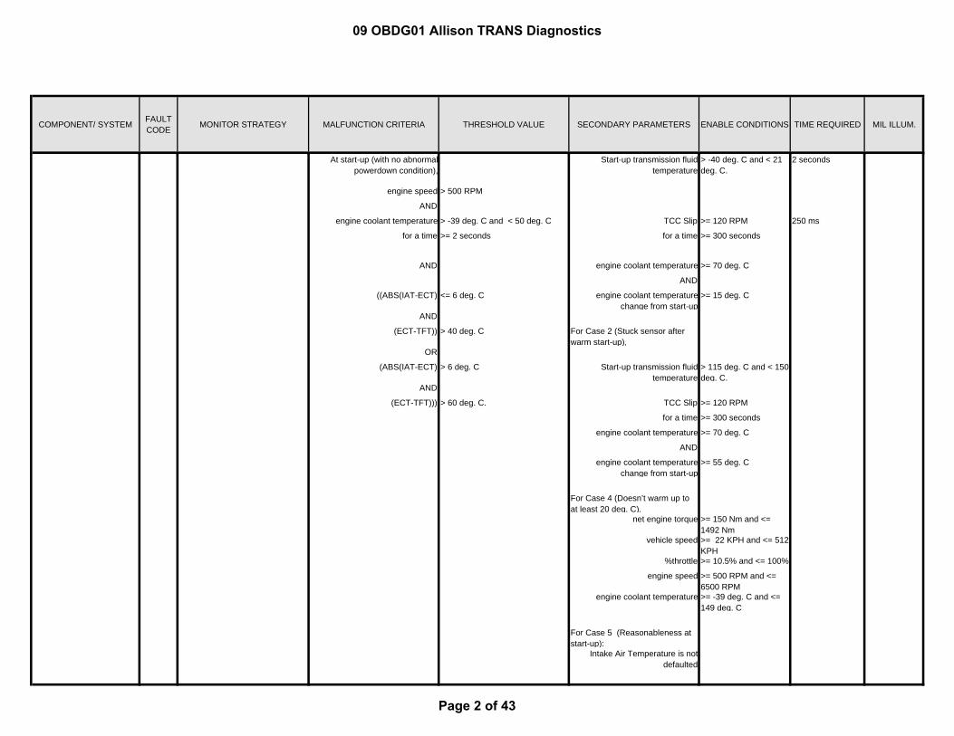
COMPONENT/ SYSTEM FAULT CODE MONITOR STRATEGY MALFUNCTION CRITERIA THRESHOLD VALUE SECONDARY PARAMETERS ENABLE CONDITIONS TIME REQUIRED MIL ILLUM.
At start-up (with no abnormal powerdown condition),
Start-up transmission fluid temperature
> -40 deg. C and < 21 deg. C.
2 seconds
engine speed > 500 RPM
AND
engine coolant temperature > -39 deg. C and < 50 deg. C TCC Slip >= 120 RPM 250 ms
for a time >= 2 seconds for a time >= 300 seconds
AND engine coolant temperature >= 70 deg. C
AND
((ABS(IAT-ECT) <= 6 deg. C engine coolant temperature change from start-up
>= 15 deg. C
AND
(ECT-TFT)) > 40 deg. C For Case 2 (Stuck sensor after warm start-up),
OR
(ABS(IAT-ECT) > 6 deg. C Start-up transmission fluid temperature
> 115 deg. C and < 150 deg. C.
AND
(ECT-TFT))) > 60 deg. C. TCC Slip >= 120 RPM
for a time >= 300 seconds
engine coolant temperature >= 70 deg. C
AND
engine coolant temperature change from start-up
>= 55 deg. C
For Case 4 (Doesn’t warm up to at least 20 deg. C),
net engine torque >= 150 Nm and <= 1492 Nm
vehicle speed >= 22 KPH and <= 512 KPH
%throttle >= 10.5% and <= 100%
engine speed >= 500 RPM and <= 6500 RPM
engine coolant temperature >= -39 deg. C and <= 149 deg. C
For Case 5 (Reasonableness at start-up):
Intake Air Temperature is not defaulted
09 OBDG01 Allison TRANS Diagnostics
Page 2 of 43
COMPONENT/ SYSTEM FAULT CODE MONITOR STRATEGY MALFUNCTION CRITERIA THRESHOLD VALUE SECONDARY PARAMETERS ENABLE CONDITIONS TIME REQUIRED MIL ILLUM.
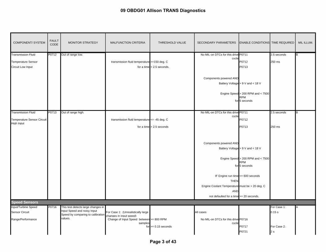
Transmission Fluid No MIL-on DTCs for this drive cycle
P0711 2.5 seconds
Temperature Sensor transmission fluid temperature >=150 deg. C P0712 250 ms
Circuit Low Input for a time > 2.5 seconds. P0713
Components powered AND
Battery Voltage > 9 V and < 18 V
Engine Speed > 200 RPM and < 7500 RPM
for 5 seconds
Transmission Fluid No MIL-on DTCs for this drive cycle
P0711 2.5 seconds
Temperature Sensor Circuit High Input
transmission fluid temperature <= -45 deg. C P0712
for a time > 2.5 seconds P0713 250 ms
Components powered AND
Battery Voltage > 9 V and < 18 V
Engine Speed > 200 RPM and < 7500 RPM
for 5 seconds
IF Engine run time <= 600 seconds
THEN
Engine Coolant Temperature must be > 20 deg. C
AND
not defaulted for a time >= 20 seconds.
Speed SensorsInput/Turbine Speed For Case 1:
Sensor Circuit For Case 1: (Unrealistically large changes in input speed)
All cases 0.15 s
Range/Performance Change of Input Speed betweensamples
>= 800 RPM No MIL-on DTCs for this drive cycle
P0716
for >= 0.15 seconds P0717 For Case 2:
P0721 2 s
B
P0713 Out of range high. B
P0712 Out of range low.
P0716 This test detects large changes in Input Speed and noisy Input Speed by comparing to calibration values.
A
09 OBDG01 Allison TRANS Diagnostics
Page 3 of 43

COMPONENT/ SYSTEM FAULT CODE MONITOR STRATEGY MALFUNCTION CRITERIA THRESHOLD VALUE SECONDARY PARAMETERS ENABLE CONDITIONS TIME REQUIRED MIL ILLUM.
For Case 2: (Noisy Input Speed) P0722
For sample size 80 For Case 3:
IF the change in Input Speed <= -800 RPM No Fault Pending DTCs for this drive cycle.
P0721 P0722
1 s
THEN the Low Counter is incremented.
25 ms
IF the change in Input Speed >= 800 RPM Shifting complete
THEN the High Counter is incremented.
For Case 1 (Unrealistically large changes in input speed) and Case 2 (Noisy Input Speed),
This test fails if both the Low Counter and the High Counter
>= 5 Input Speed > 200 RPM
OR for >= 0.5 seconds
High Counter >= 5
For Case 3 (Wires to speed sensors swapped),
For Case 3: (Wires to speed sensors swapped)
Input speed > 100 RPM
Increment counter when rangeattained and range commanded
are neutral for a time<= 3.5 seconds
Engine speed > 100 RPM
AND Hydraulic system pressurized
when ratio of engine speed andinput speed >= 3
Enables met
Arm test when counter >=20 AND
OR No MIL-on DTCs P0716
when time > 3.5 seconds P0717
for a time >= 0.2 seconds
Malfunction is reported when, fora time
> 0.5 seconds
the range commanded is NOT neutral
AND
the on-coming clutch control is complete
AND
input speed > 100 RPM
AND
engine speed > 100 RPM
09 OBDG01 Allison TRANS Diagnostics
Page 4 of 43
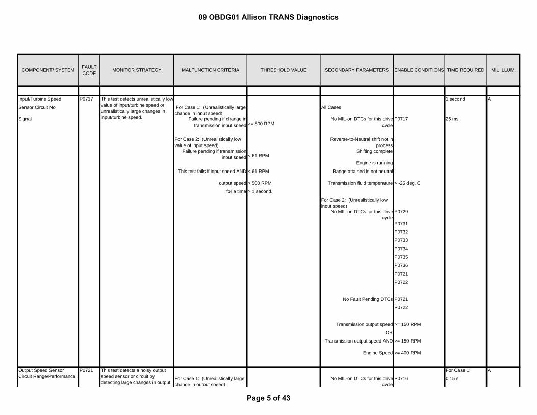
COMPONENT/ SYSTEM FAULT CODE MONITOR STRATEGY MALFUNCTION CRITERIA THRESHOLD VALUE SECONDARY PARAMETERS ENABLE CONDITIONS TIME REQUIRED MIL ILLUM.
Input/Turbine Speed 1 second
Sensor Circuit No For Case 1: (Unrealistically large change in input speed)
All Cases
Signal Failure pending if change in transmission input speed >= 800 RPM
No MIL-on DTCs for this drive cycle
P0717 25 ms
For Case 2: (Unrealistically low value of input speed)
Reverse-to-Neutral shift not in process
Failure pending if transmission input speed < 61 RPM
Shifting complete
Engine is running
This test fails if input speed AND < 61 RPM Range attained is not neutral
output speed > 500 RPM Transmission fluid temperature > -25 deg. C
for a time > 1 second.
For Case 2: (Unrealistically low input speed)
No MIL-on DTCs for this drive cycle
P0729
P0731
P0732
P0733
P0734
P0735
P0736
P0721
P0722
No Fault Pending DTCs P0721
P0722
Transmission output speed >= 150 RPM
OR
Transmission output speed AND >= 150 RPM
Engine Speed >= 400 RPM
For Case 1:
For Case 1: (Unrealistically large change in output speed)
No MIL-on DTCs for this drive cycle
P0716 0.15 s
Output Speed Sensor Circuit Range/Performance
P0721 This test detects a noisy output speed sensor or circuit by detecting large changes in output
d
A
P0717 This test detects unrealistically low value of input/turbine speed or unrealistically large changes in input/turbine speed.
A
09 OBDG01 Allison TRANS Diagnostics
Page 5 of 43

COMPONENT/ SYSTEM FAULT CODE MONITOR STRATEGY MALFUNCTION CRITERIA THRESHOLD VALUE SECONDARY PARAMETERS ENABLE CONDITIONS TIME REQUIRED MIL ILLUM.
Change in output speed >= 500 RPM P0717
for a time >= 0.15 seconds P0721 For Case 2:
P0722 2 seconds
For Case 2: (Noisy output speed) 25 ms
For sample size 80 No Fault Pending DTCs for this drive cycle
P0716 P0717
IF the change in output speed <= -500 RPM
THEN the Low Counter is incremented.
Output Speed > 200 RPM
IF the change in output speed >= 500 RPM for a time >= 0.5 seconds
THEN the High Counter is incremented.
Test fails if both the Low Counter and the High Counter
>= 5 Shift complete
OR AND
the Low Counter >= 5 range attained NOT neutral
OR
the High Counter >= 5
Output Speed Sensor All Cases 1 second
Circuit No Signal For Case 1: (Unrealistically large change in output speed)
No MIL-on DTCs for this drive cycle.
P0721 25 ms
Failure pending if
change in output speed >= 600 RPM For Case 1: (Unrealistically large change in output speed)
Failure sets if range attained is Neutral.
Test enabled when output speed >= 600 RPM
For Case 2: (Unrealistically low value of output speed)
for a time >= 1 seconds
Failure pending if output speed < 61 RPM
Failure sets if not monitoring for low speed neutral and output
speed
< 61 RPM Test disabled when output speed <= 600 RPM
AND for a time > 1 seconds
range 3rd, 4th, 5th, or 6th
for a time > 1 second For Case 2: (Unrealistically low value of output speed)
No MIL-on DTCs for this drive cycle.
P0731
Failure sets if not monitoring for low speed neutral and output
speed
< 61 RPM P0732
AND P0733
speed.
P0722 This test detects unrealistically low value of output speed or unrealistically large change in output speed.
A
09 OBDG01 Allison TRANS Diagnostics
Page 6 of 43

COMPONENT/ SYSTEM FAULT CODE MONITOR STRATEGY MALFUNCTION CRITERIA THRESHOLD VALUE SECONDARY PARAMETERS ENABLE CONDITIONS TIME REQUIRED MIL ILLUM.
((net engine torque < -100 Nm P0734
OR P0735
net engine torque) > 100 Nm P0736
OR P0716
(turbine speed > 1500 RPM P0717
AND
range)) 2nd No Fault Pending DTCs for this drive cycle
P0716, P0717
for a time >= 4 seconds.
Engine is running
Shift not in process
Range attained is not Neutral
Reverse to Neutral shift not in process
Transmission fluid temperature > -25 deg. C
Transmission input speed >= 1050 RPM
Not waiting for Manual Selector Valve to attain forward range
PRNDL State NOT D4
NOT Transitional D4
NOT Transitional N
Range Verifiication
2.25 seconds
Pending failure occurs when accumulated event timer >= 2 second
No MIL-on DTCs for this drive cycle.
P0877 25 ms
Timer accumulates when transmission is in range forward or reverse
P0878
AND P0721
output speed >= 100 RPM P0722
AND P0716
Gear 1 Incorrect Ratio P0731 This test verifies transmission operating ratio while 1st range is commanded by comparing computed ratio to the commanded ratio.
A
09 OBDG01 Allison TRANS Diagnostics
Page 7 of 43

COMPONENT/ SYSTEM FAULT CODE MONITOR STRATEGY MALFUNCTION CRITERIA THRESHOLD VALUE SECONDARY PARAMETERS ENABLE CONDITIONS TIME REQUIRED MIL ILLUM.
gear slip > 100 RPM P0717
No Fault Pending DTC for this drive cycle. P0717
In response to pending failure, adiagnostic response range is
commanded. During this command, this test
fails if Abs(Converter Slip) >= 230 RPMNo range switch response active
for > 10 samples.
Hydraulic System Pressurized
Shift complete
Output speed >= 200 RPM
No hydraulic default conditionpresent
Normal powertrain shutdown not in process
Normal powertrain initialization is complete
This test verifies transmission operating ratio while 2nd range
2.25 seconds
is commanded by comparing computed ratio to the commanded ratio.
Pending failure occurs when accumulated event timer
>= 2 second No MIL-on DTCs for this drive cycle.
P0877 25 ms
Timer accumulates when transmission is in range forward or reverse
P0878
AND P0721
output speed >= 100 RPM P0722
AND P0716
gear slip > 100 RPM P0717
No Fault Pending DTC for this drive cycle. P0717
In response to pending failure, adiagnostic response range is
commanded. During this command, this test
fails if Abs(Converter Slip) >= 230 RPMNo range switch response active
for > 10 samples.
Hydraulic System Pressurized
Gear 2 Incorrect Ratio P0732 A
09 OBDG01 Allison TRANS Diagnostics
Page 8 of 43

COMPONENT/ SYSTEM FAULT CODE MONITOR STRATEGY MALFUNCTION CRITERIA THRESHOLD VALUE SECONDARY PARAMETERS ENABLE CONDITIONS TIME REQUIRED MIL ILLUM.
Shift complete
Output speed >= 200 RPM
No hydraulic default conditionpresent
Normal powertrain shutdown not in process
Normal powertrain initialization is complete
2.25 seconds
Pending failure occurs when accumulated event timer >= 2 second
No MIL-on DTCs for this drive cycle.
P0877 25 ms
Timer accumulates when transmission is in range forward or reverse
P0878
AND P0721
output speed >= 100 RPM P0722
AND P0716
gear slip > 100 RPM P0717
No Fault Pending DTC for this drive cycle. P0717
In response to pending failure, adiagnostic response range is
commanded. During this command, this test
fails if Abs(Converter Slip) >= 230 RPMNo range switch response active
for > 10 samples.
Hydraulic System Pressurized
Shift complete
Output speed >= 200 RPM
No hydraulic default conditionpresent
Normal powertrain shutdown not in process
Gear 3 Incorrect Ratio P0733 This test verifies transmission operating ratio while 3rd range is commanded by comparing computed ratio to the commanded ratio.
A
09 OBDG01 Allison TRANS Diagnostics
Page 9 of 43

COMPONENT/ SYSTEM FAULT CODE MONITOR STRATEGY MALFUNCTION CRITERIA THRESHOLD VALUE SECONDARY PARAMETERS ENABLE CONDITIONS TIME REQUIRED MIL ILLUM.
Normal powertrain initialization is complete
2.25 seconds
Pending failure occurs when accumulated event timer >= 2 second
No MIL-on DTCs for this drive cycle.
P0877 25 ms
Timer accumulates when transmission is in range forward or reverse
P0878
AND P0721
output speed >= 100 RPM P0722
AND P0716
gear slip > 100 RPM P0717
No Fault Pending DTC for this drive cycle. P0717
In response to pending failure, adiagnostic response range is
commanded. During this command, this test
fails if Abs(Converter Slip) >= 230 RPMNo range switch response active
for > 10 samples.
Hydraulic System Pressurized
Shift complete
Output speed >= 200 RPM
No hydraulic default conditionpresent
Normal powertrain shutdown not in process
Normal powertrain initialization is complete
2.25 seconds
Pending failure occurs when accumulated event timer >= 2 second
No MIL-on DTCs for this drive cycle. P0877
25 ms
Timer accumulates when transmission is in range forward or reverse P0878
AND P0721
output speed >= 100 RPM P0722
AND P0716
gear slip > 100 RPM P0717
Gear 5 Incorrect Ratio P0735 This test verifies transmission operating ratio while 5th range is commanded by comparing computed ratio to the commanded ratio.
A
Gear 4 Incorrect Ratio P0734 This test verifies transmission operating ratio while 4th range is commanded by comparing computed ratio to the commanded ratio.
A
09 OBDG01 Allison TRANS Diagnostics
Page 10 of 43

COMPONENT/ SYSTEM FAULT CODE MONITOR STRATEGY MALFUNCTION CRITERIA THRESHOLD VALUE SECONDARY PARAMETERS ENABLE CONDITIONS TIME REQUIRED MIL ILLUM.
No Fault Pending DTC for this drive cycle.
P0717
In response to pending failure, adiagnostic response range is
commanded. During this command, this test
fails if Abs(Converter Slip) >= 230 RPM No range switch response active
for > 10 samples.
Hydraulic System Pressurized
Shift complete
Output speed >= 200 RPM
No hydraulic default conditionpresent
Normal powertrain shutdown not in process
Normal powertrain initialization is complete
2 seconds
Accumulated event timer >= 2 seconds No MIL-on DTCs for this drive cycle.
P0877 25 ms
P0878
Timer accumulates when transmission range
forward or reverse P0721
AND P0722
output speed >= 100 RPM P0716
AND P0717
gear slip > 100 RPM No Fault Pending DTC for this drive cycle.
P0717
No range switch response active
Hydraulic System Pressurized
Shift complete
Reverse Incorrect Ratio P0736 This test verifies transmission range while reverse range is commanded by comparing computed ratio to the commanded ratio.
A
09 OBDG01 Allison TRANS Diagnostics
Page 11 of 43

COMPONENT/ SYSTEM FAULT CODE MONITOR STRATEGY MALFUNCTION CRITERIA THRESHOLD VALUE SECONDARY PARAMETERS ENABLE CONDITIONS TIME REQUIRED MIL ILLUM.
Output speed >= 200 RPM
No hydraulic default conditionpresent
Normal powertrain shutdown not in process
Normal powertrain initialization is complete
2.25 seconds
Pending failure occurs when accumulated event timer
>= 2 second No MIL-on DTCs for this drive cycle.
P0877 25 ms
Timer accumulates when transmission is in range
forward or reverse P0878
AND P0721
output speed >= 100 RPM P0722
AND P0716
gear slip > 100 RPM P0717
No Fault Pending DTC for this drive cycle.
P0717
In response to pending failure, adiagnostic response range is
commanded. During this command, this test
fails if Abs(Converter Slip) >= 230 RPM No range switch response active
for > 10 samples.
Hydraulic System Pressurized
Shift complete
Output speed >= 200 RPM
No hydraulic default conditionpresent
Normal powertrain shutdown not in process
Normal powertrain initialization is complete
Gear 6 Incorrect Ratio P0729 This test verifies transmission operating ratio while 6th range is commanded by comparing computed ratio to the commanded ratio.
A
09 OBDG01 Allison TRANS Diagnostics
Page 12 of 43

COMPONENT/ SYSTEM FAULT CODE MONITOR STRATEGY MALFUNCTION CRITERIA THRESHOLD VALUE SECONDARY PARAMETERS ENABLE CONDITIONS TIME REQUIRED MIL ILLUM.
Torque Converter ClutchTorque Converter This test detects the torque 15 s
Clutch Circuit converter being stuck off (unlocked).
TCC Slip >= 80 RPM No MIL-on DTCs for this drive cycle.
P2761 100 ms
Performance or Stuck for a time >= 15 seconds. P2763
Off P2764
P0721
P0722
P0716
P0717
No Fault Pending DTCs for this drive cycle.
P2761
P2763
P2764
P0721
P0722
P0716
P0717
Components powered AND
Battery Voltage > 9 V and < 18 V
Engine Speed > 200 RPM and < 7500 RPM
5 seconds
for
Must be in forward range
% Throttle > 10 % and <= 90 %
Transmission fluid temperature > 5 deg. C and < 130 deg. C
Time Since Range Change >= 6 seconds
AND
P0741 B
09 OBDG01 Allison TRANS Diagnostics
Page 13 of 43

COMPONENT/ SYSTEM FAULT CODE MONITOR STRATEGY MALFUNCTION CRITERIA THRESHOLD VALUE SECONDARY PARAMETERS ENABLE CONDITIONS TIME REQUIRED MIL ILLUM.
TCC apply is complete
TCC pressure >= 1000 kPa
Torque Converter This test detects the torque No MIL-on DTCs for this drive cycle.
P2761 Case 1
Clutch Circuit Stuck On converter being stuck on (locked). Case 1: (High Torque condition) P2763 2 s
Set fault pending when throttle >= 70% P2764 Case 2
AND P0721 5 s
net engine torque >= 275 Nm. P0722 Case 3
P0716 10.5 s
Report malfunction when fault pending exists continuously
P0717
for a time >= 2 seconds. U0100 100 ms
No Fault Pending DTCs for this drive cycle.
P2761
Case 2: (High Acceleration condition)
P2763
Set fault pending when output shaft acceleration >= 100 RPM/second
P2764
P0721
Report malfunction when fault pending exists continuously
P0722
for a time >= 5 seconds. P0716
P0717
Case 3: (Accel/Decel/Accel condition)
U0100
Report malfunction when output acceleration event is followed by
output deceleration event and followed by another output
acceleration event. An output acceleration event occurs when
output shaft acceleration >= 40 RPM/second
Components powered AND
for a time >= 4 seconds Battery Voltage > 9 V and < 18 V
An output deceleration event occurs when output shaft
acceleration is <=-40 RPM/second
Engine Speed > 200 RPM and < 7500 RPM
for a time >= 2.5 seconds. for 5 seconds
P0742 B
09 OBDG01 Allison TRANS Diagnostics
Page 14 of 43

COMPONENT/ SYSTEM FAULT CODE MONITOR STRATEGY MALFUNCTION CRITERIA THRESHOLD VALUE SECONDARY PARAMETERS ENABLE CONDITIONS TIME REQUIRED MIL ILLUM.
Must be in forward range
TCC is off
TCC Slip >=-20 RPM and <= 20 RPM
% Throttle >= 25%
Net Engine Torque >= 175 Nm
Engine speed <= 3500 RPM
Input speed <= 3500 RPM
Output speed >= 100 RPM
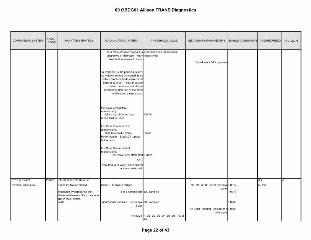
Pressure Switches
This test compares the 100 ms
commanded valve position to the PS1 pressure switch feedback. (part of S1 valve integrity test)
Pending failure occurs when PS1 pressure switch indicates stroked
for a time
> 0.08 seconds S1 valve is destroked 25 ms
IF a main pressure dropout is suspected or detected, THEN
time limit increases to times
0.125 seconds and 30 seconds, respectively
NOT Cold initialization unless transmission fluid temperature
> -25 deg. C
Shutdown is NOT in process
In response to the pending failure,S1 valve is retried by triggering S1
valve command to stroked and back to destroked. If PS1
pressure switch continues to indicate stroked, then one of three
malfunction cases exists:
For Case 1 (electrical malfunction), SS1 Circuit Low reports failure, also.
P0793
Pressure Switch Solenoid 1 Circuit Low
P0842 A
09 OBDG01 Allison TRANS Diagnostics
Page 15 of 43

COMPONENT/ SYSTEM FAULT CODE MONITOR STRATEGY MALFUNCTION CRITERIA THRESHOLD VALUE SECONDARY PARAMETERS ENABLE CONDITIONS TIME REQUIRED MIL ILLUM.
For Case 2 (mechanical malfunction), Shift Solenoid 1 (SS1) Valve Performance – Stuck On reports failure, also.
P0752
For Case 3 (intermittent malfunction),
SS1 valve retry attempted 15 times
AND
PS1 pressure switch continues to indicate stroked.
This test compares the 5 seconds
change of state of the valve command to the change of state of the PS1 pressure switch feedback. (part of the S1 valve timeout test)
S1 valve is commanded from destroked to stroked and the PS1
pressure switch indication remains destroked for a time
>= 5 seconds 25 ms
WITH
transmission fluid temperature >= 0 deg. C
(Time increases as temperature decreases with maximum time
12 seconds
at
transmission fluid temperature) <= -40 deg. C
This test compares the 6.6 seconds
change of state of the valve command to the change of state of the PS1 pressure switch feedback. (part of the S1 valve timeout test).
S1 valve commanded from stroked to destroked and the PS1
pressure switch indication remains stroked for a time
> 6.6 seconds S1 valve changes from stroked to destroked
25 ms
WITH
transmission fluid temperature >= 0 deg. C.
(Time increases as
temperature decreases with maximum time
at 11 seconds
S1 valve commanded from destroked to stroked.
Shift Solenoid 1 (SS1) Valve Performance – Stuck On
P0752 A
AShift Solenoid 1 (SS1) Valve Performance – Stuck Off
P0751
09 OBDG01 Allison TRANS Diagnostics
Page 16 of 43

COMPONENT/ SYSTEM FAULT CODE MONITOR STRATEGY MALFUNCTION CRITERIA THRESHOLD VALUE SECONDARY PARAMETERS ENABLE CONDITIONS TIME REQUIRED MIL ILLUM.
transmission fluid temperature) <= -40 deg. C
This test compares the
commanded valve position to the PS1 pressure switch feedback. (part of S1 valve integrity test)
Pending failure occurs when PS1 pressure switch indicates
destroked for a time
> 0.07 seconds S1 valve is stroked 70 ms
25 ms
IF a main pressure dropout is suspected or detected, then time
limit increases to times
5 seconds and 30 seconds, respectively.)
NOT Cold initialization unless transmission fluid temperature
> -25 deg. C
In response to the pending failure,S1 valve is retried by triggering S1valve command to destroked and
back to stroked. If the PS1 pressure switch continues to
indicate destroked, then one of three malfunction cases exists.
Shutdown NOT in process
For Case 1 (electrical malfunction),
P0793
SS1 Control Circuit Low reports failure, also.
For Case 2 (mechanical malfunction), Shift Solenoid 1 (SS1) Valve Performance – Stuck Off reports failure, also.
P0751
For Case 3 (intermittent malfunction),
S1 valve retry attempted 15 times
AND
PS1 pressure switch continues to indicate destroked.
This test compares the 40 ms
Pressure Switch Solenoid 1 Circuit High
P0843 A
Pressure Switch Solenoid 2 Circuit Low
P0847 A
09 OBDG01 Allison TRANS Diagnostics
Page 17 of 43

COMPONENT/ SYSTEM FAULT CODE MONITOR STRATEGY MALFUNCTION CRITERIA THRESHOLD VALUE SECONDARY PARAMETERS ENABLE CONDITIONS TIME REQUIRED MIL ILLUM.
commanded valve position to the PS2 pressure switch
Pending failure occurs when PS2 pressure switch indicates stroked
for a time
> 0.04004 seconds S2 valve is destroked 25 ms
feedback (part of the S2 valve integrity test).
IF a main pressure dropout is suspected or detected, THEN
time limit increases to times
0.04 seconds and 30 seconds, respectively.
NOT Cold initialization unless transmission fluid temperature
> -25 deg. C
In response to the pending failure,S2 valve is retried by triggering S2
valve command to stroked and back to destroked. If PS2
pressure switch continues to indicate stroked, then one of three
malfunction cases exists.
Shutdown is NOT in process
For Case 1 (electrical malfunction), SS2 Control Circuit Low reports failure, also.
P0976
For Case 2 (mechanical malfunction), Shift Solenoid 2 Valve Performance – Stuck On reports failure, also.
P0757
For Case 3 (intermittent malfunction),
S2 valve retry attempted 2 times
AND
PS2 pressure switch continues to indicate stroked.
This test compares the 5 seconds
change of state of the valve command to the change of state of the PS2 pressure switch feedback (part of the S2 valve timeout test).
If the S2 valve is commanded from destroked to stroked and the
PS2 pressure switch indication remains destroked for a time
>= 5 seconds 25 ms
WITH
transmission fluid temperature >= 0 deg. C.
P0756 S2 valve commanded from destroked to stroked.
AShift Solenoid 2 Valve Performance – Stuck Off
09 OBDG01 Allison TRANS Diagnostics
Page 18 of 43

COMPONENT/ SYSTEM FAULT CODE MONITOR STRATEGY MALFUNCTION CRITERIA THRESHOLD VALUE SECONDARY PARAMETERS ENABLE CONDITIONS TIME REQUIRED MIL ILLUM.
(Time increases as temperature decreases with maximum time
12 seconds
at
transmission fluid temperature) <= -40 deg. C.
This test compares the 6.4 seconds
commanded valve position to the PS2 pressure switch
S2 valve commanded from stroked to destroked and the PS2 pressure switch does not indicate
destroked for a time
>= 6.4 seconds S2 valve changes from stroked to destroked
25 ms
feedback (part of the S2 valve timeout test).
WITH
transmission fluid temperature >= 0 deg. C.
(Time increases as temperature decreases with maximum time
15 seconds
at
transmission fluid temperature) <= -40 deg. C.
300 ms
Pending failure occurs when PS2 pressure switch indicates
destroked for a time
> 0.30 seconds S2 valve is stroked 25 ms
IF a main pressure dropout is suspected or detected, THEN
time limit increases to times
5 seconds and 30 seconds, respectively.)
NOT Cold initialization unless transmission fluid temperature
> -25 deg. C
In response to the pending failure,S2 valve is retried by triggering S2valve command to destroked and back to stroked. If PS2 pressure
switch continues to indicate destroked, then one of three
malfunction cases exists.
Shutdown NOT in process
For Case 1 (electrical malfunction), SS2 Control Circuit Low reports failure, also.
P0976
Pressure Switch Solenoid 2 Circuit High
P0848 This test compares the commanded valve position to the PS2 pressure switch feedback (part of the S2 valve integrity test).
A
Shift Solenoid 2 Valve Performance – Stuck On
P0757 A
09 OBDG01 Allison TRANS Diagnostics
Page 19 of 43

COMPONENT/ SYSTEM FAULT CODE MONITOR STRATEGY MALFUNCTION CRITERIA THRESHOLD VALUE SECONDARY PARAMETERS ENABLE CONDITIONS TIME REQUIRED MIL ILLUM.
For Case 2 (mechanical malfunction), Shift Solenoid 2 Valve Performance – Stuck Off reports failure, also.
P0756
For Case 3 (intermittent malfunction),
S2 valve retry attempted 2 times
AND
PS2 pressure switch continues to indicate destroked.
This test compares the 20 ms
commanded valve position to the PS3 pressure switch
Pending failure occurs when PS3 pressure switch indicates stroked
for a time
> 0.0195 seconds S3 valve is destroked 25 ms
feedback. (part of S3 valve integrity test)
IF a main pressure dropout is suspected or detected, THEN
time limit increases to
NOT Cold initialization unless transmission fluid temperature
> -25 deg. C
In response to the pending failure,S3 valve is retried by triggering S3
valve command to stroked and back to destroked. If PS3
pressure switch continues to indicate stroked, then one of three
malfunction cases exists.
0.125 seconds and 30 seconds, respectively
Shutdown is NOT in process
For Case 1 (electrical malfunction), SS3 Control Circuit Low reports failure, also.
P0979
For Case 2 (mechanical malfunction), Shift Solenoid 3 Valve Performance – Stuck On reports failure, also.
P0762
For Case 3 (intermittent malfunction),
S3 valve retry attempted 2 times
Pressure Switch Solenoid 3 Circuit Low
P0872 A
09 OBDG01 Allison TRANS Diagnostics
Page 20 of 43

COMPONENT/ SYSTEM FAULT CODE MONITOR STRATEGY MALFUNCTION CRITERIA THRESHOLD VALUE SECONDARY PARAMETERS ENABLE CONDITIONS TIME REQUIRED MIL ILLUM.
AND
PS3 pressure switch continues to indicate stroked.
5 seconds
If the S3 valve is commanded from destroked to stroked and the
PS3 pressure switch indication remains destroked for a time
>= 5 seconds 25 ms
WITH
transmission fluid temperature >= 0 deg. C.
(Time increases as temperature decreases with maximum time
12 seconds
at
transmission fluid temperature) <= -40 deg. C.
This test compares the 6.6 seconds
commanded valve position to the PS3 pressure switch
S3 valve commanded from stroked to destroked and the PS3 pressure switch does not indicate
destroked for a time
> 6.6 seconds S3 valve changes from stroked to destroked
25 ms
feedback (part of the S3 valve timeout test).
WITH
transmission fluid temperature >= 0 deg. C.
(Time increases as temperature decreases with maximum time
15 seconds
at
transmission fluid temperature) >= -40 deg. C.
This test compares the 300 ms
commanded valve position to the pressure switch PS3
Pending failure occurs when PS3 pressure switch
> 0.30 seconds S3 valve is stroked 25 ms
feedback. (part of S3 valve integrity test)
indicates destroked for a time
NOT Cold initialization unless transmission fluid temperature
> -25 deg. C
Shift Solenoid 3 Valve Performance – Stuck Off
P0761 This test compares the change of state of the valve command to the change of state of the PS3 pressure switch feedback. (part of the S3 valve timeout test)
S3 valve commanded from destroked to stroked.
A
Pressure Switch Solenoid 3 Circuit High
P0873 A
Shift Solenoid 3 Valve Performance – Stuck On
P0762 A
09 OBDG01 Allison TRANS Diagnostics
Page 21 of 43
COMPONENT/ SYSTEM FAULT CODE MONITOR STRATEGY MALFUNCTION CRITERIA THRESHOLD VALUE SECONDARY PARAMETERS ENABLE CONDITIONS TIME REQUIRED MIL ILLUM.
IF a main pressure dropout is suspected or detected, THEN
time limit increases to times
5 seconds and 30 seconds, respectively
Shutdown NOT in process
In response to the pending failure,S3 valve is retried by triggering S3valve command to destroked and back to stroked. If PS3 pressure
switch continues to indicate destroked, then one of the three
malfunction cases exists.
For Case 1 (electrical malfunction), SS3 Control Circuit Low reports failure, also.
P0979
For Case 2 (mechanical malfunction), Shift Solenoid 3 Valve Performance – Stuck Off reports failure, also.
P0761
For Case 3 (intermittent malfunction),
S3 valve retry attempted 2 times
AND
PS3 pressure switch continues to indicate destroked.
Pressure Switch This test detects Reverse 3 s
Reverse Circuit Low Pressure Switch closed Case 1: (Forward range) No MIL-on DTCs for this drive cycle.
P0877 50 ms
indication by comparing the Reverse Pressure Switch state to the PRNDL switch
For a sample size 100 samples P0878
state. (if dropouts detected, use sample size),
200 samples P0708
No Fault Pending DTCs for this drive cycle
P0708
PRNDL is P, D1, D2, D3, D4, D5, D6, T8, or T4
P0877 A
09 OBDG01 Allison TRANS Diagnostics
Page 22 of 43

COMPONENT/ SYSTEM FAULT CODE MONITOR STRATEGY MALFUNCTION CRITERIA THRESHOLD VALUE SECONDARY PARAMETERS ENABLE CONDITIONS TIME REQUIRED MIL ILLUM.
Engine is Running
AND
RPS indicates Reverse Components powered AND
for a time >= 1 seconds Battery Voltage > 9 V and < 18 V
(if dropouts detected, use time). 30 seconds
Engine Speed > 200 RPM and < 7500 RPM
Case 2: (Range indefinite) for 5 seconds
For a sample size, 20 samples
net engine torque >= 100 Nm Transmission Fluid Temperature >= 0 deg. C
AND
PRNDL is indefinitely D3 or another forward range
Hydraulic System is Pressurized
for a time > 1 second
Reverse Pressure Switch State indicates
REVERSE
Pressure Switch Case 1:
Reverse Circuit High For Case 1: (RPS State and PRNDL State do not agree)
For All Cases: 3 s
For sample size 40 samples Transmission Fluid Temperature >= 0 deg. C Case 2:
PRNDL is REVERSE 60 s
AND For Case 1: (RPS State and PRNDL State do not agree)
50 ms
RPS indicates not Reverse
after a time >= 1 second No MIL-on DTCs for this drive cycle
P0877
For Case 2: (RPS Shutdown Test)
P0878
If RPS indicates not Reverse P0708
for a time > 40 seconds No Fault Pending DTC for this drive cycle.
P0708
at transmission fluid temperature 0 deg. C.
Battery Voltage > 9 V and < 18 V
This time varies with transmission fluid temperature,
from time
25 seconds
at transmission fluid temperature > 35 deg. C No range switch response active
to time 60 seconds
P0878 This test detects the Reverse Pressure switch being stuck in the open position by comparing to the PRNDL switch state and detects the Reverse Pressure switch stuck open at shutdown.
A
09 OBDG01 Allison TRANS Diagnostics
Page 23 of 43

COMPONENT/ SYSTEM FAULT CODE MONITOR STRATEGY MALFUNCTION CRITERIA THRESHOLD VALUE SECONDARY PARAMETERS ENABLE CONDITIONS TIME REQUIRED MIL ILLUM.
at transmission fluid temperature < -20 deg. C. For Case 2: (RPS Shutdown Test)
Ignition Key State is NOT RUN
Engine Stopped or Stalled
End of Trip timer >= 5 seconds
Engine had been cranking or running this drive cycle
Engine speed < 50 RPM
Turbine speed < 50 RPM
Output speed < 50 RPM
On-coming/Off-going Ratio
2.25 s
Pending failure occurs when accumulated event timer
>= 2 seconds No MIL-on DTCs for this drive cycle.
P0721 25 ms
(For rough road conditions, use) 2 seconds P0722
P0716
Timer accumulates when transmission is shifting,
P0717
output speed >= 60 RPM P0877
AND commanded gear slip speed > 75 RPM P0878
(For rough road conditions, use) 150 RPM. Output Speed >= 125 RPM
Turbine Speed >= 60 RPM
In response of pending failure, adiagnostic response range is
commanded. During this command, this test fails if
ABS(Converter slip)
>= 230 RPM Hydraulic System Pressurized
for sample size > 10 samples Normal powertrain shutdown not in process
Normal or Cold powertrain initialization is complete
No range switch response active
No Cold Mode operation
No abusive garage shift to 1st range detected
Pressure Control Solenoid 1 Controlled Clutch Stuck Off
P2723 This test determines if the on-coming clutch energized by Pressure Control Solenoid 1 engages during a forward range shift.
A
09 OBDG01 Allison TRANS Diagnostics
Page 24 of 43

COMPONENT/ SYSTEM FAULT CODE MONITOR STRATEGY MALFUNCTION CRITERIA THRESHOLD VALUE SECONDARY PARAMETERS ENABLE CONDITIONS TIME REQUIRED MIL ILLUM.
On-coming clutch control enabled
Power downshift abort to previousrange NOT active
2.25 s
Pending failure occurs when accumulated event timer
>= 2 seconds No MIL-on DTCs for this drive cycle.
P0721 25 ms
(For rough road conditions, use) 2 seconds P0722
P0716
Timer accumulates when transmission is shifting,
P0717
output speed >= 60 RPM P0877
AND commanded gear slip speed > 75 RPM P0878
(For rough road conditions, use) 150 RPM. Output Speed >= 125 RPM
Turbine Speed >= 60 RPM
In response of pending failure, adiagnostic response range is
commanded. During this command, this test fails if
ABS(Converter slip)
>= 230 RPM Hydraulic System Pressurized
for sample size > 10 samples Normal powertrain shutdown not in process
Normal or Cold powertrain initialization is complete
No range switch response active
No Cold Mode operation
No abusive garage shift to 1st range detected
On-coming clutch control enabled
Power downshift abort to previousrange NOT active
3 s
Accumulated fail timer >= 0.2998 seconds No MIL-on DTCs for this drive cycle.
P0721 25 ms
for forward range upshift; P0722
OR accumulated fail timer >= 3.0 seconds P0716
for direction change shifts; P0717
Pressure Control Solenoid 1 Controlled Clutch Stuck On
P2724 This test determines if the off-going clutch energized by Pressure Control solenoid 1 remains engaged during a forward range shift.
A
Pressure Control Solenoid 2 Controlled Clutch Stuck Off
P0776 This test determines if the on-coming clutch energized by Pressure Control Solenoid 2 engages during a forward range shift.
A
09 OBDG01 Allison TRANS Diagnostics
Page 25 of 43

COMPONENT/ SYSTEM FAULT CODE MONITOR STRATEGY MALFUNCTION CRITERIA THRESHOLD VALUE SECONDARY PARAMETERS ENABLE CONDITIONS TIME REQUIRED MIL ILLUM.
OR accumulated fail timer >= 0.500 seconds P0877
for forward range closed throttledownshift;
P0878
OR accumulated fail timer >= 1.0 second No Fault Pending DTC for this drive cycle.
P0717
for forward downshifts aboveclosed throttle.
Output Speed >= 200 RPM
Fail timer accumulates during range to range shifts when
attained gear slip speed
<= 25 RPM Turbine Speed >= 200 RPM
Normal powertrain shutdown not in process
Normal or Cold powertrain initialization is complete
No range switch response active
No Cold Mode operation
No abusive garage shift to 1st range detected
Pressure Control Solenoid 2 Controlled Clutch
3 s
Stuck On Accumulated fail timer >= 0.2998 seconds No MIL-on DTCs for this drive cycle.
P0721 25 ms
for forward range upshift; P0722
OR accumulated fail timer >= 3.0 seconds P0716
for direction change shifts; P0717
OR accumulated fail timer >= 0.500 seconds P0877
for forward range closed throttledownshift;
P0878
OR accumulated fail timer >= 1.0 second No Fault Pending DTC for this drive cycle.
P0717
for forward downshifts aboveclosed throttle.
Output Speed >= 200 RPM
Fail timer accumulates during range to range shifts when
attained gear slip speed
<= 25 RPM Turbine Speed >= 200 RPM
Normal powertrain shutdown not in process
Normal or Cold powertrain initialization is complete
No range switch response active
No Cold Mode operation
P0777 This test determines if the off-going clutch energized by Pressure Control solenoid 2 remains engaged during a forward range shift.
A
09 OBDG01 Allison TRANS Diagnostics
Page 26 of 43

COMPONENT/ SYSTEM FAULT CODE MONITOR STRATEGY MALFUNCTION CRITERIA THRESHOLD VALUE SECONDARY PARAMETERS ENABLE CONDITIONS TIME REQUIRED MIL ILLUM.
No abusive garage shift to 1st range detected
PRNDL/IMSThis test monitors the Case 1:
transmission range switch for invalid input conditions and parity errors occurring over consecutive ignition cycles.
For Case 1 (No Information): Components powered 1 s
Illegal electrical state for a time >= 1 second AND Case 2:
Battery Voltage > 9 V and < 18 V 5th occurrenceFor Case 2 (Long-term Parity):
There are 3 counters for long-term parity. These counters are
updated at the end of each drive cycle, immediately prior to TCM
shutdown.
Engine Speed > 200 RPM and < 7500 RPM
100 ms
for 5 seconds
For Counter 1, increment counter IF Parity Error Detected;
decrement counter IF No ParityError Detected AND No Motion
Detected. IF Counter 1 >= 15 counts
THEN report failure.
For Counter 2, increment counter IF Parity Error Detected AND (NoValid Drive Detected OR No Valid
Park/Neutral Detected) AND Motion Detected; decrement
counter IF No Parity ErrorDetected AND Valid Park/Neutral
Detected AND Valid Drive Detected AND Motion Detected.
IF Counter 2, >= 5 counts
THEN report failure.
Transmission Range Sensor High Input
P0708 A
09 OBDG01 Allison TRANS Diagnostics
Page 27 of 43
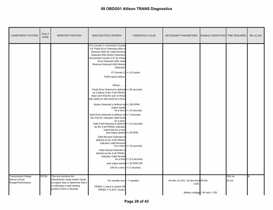
COMPONENT/ SYSTEM FAULT CODE MONITOR STRATEGY MALFUNCTION CRITERIA THRESHOLD VALUE SECONDARY PARAMETERS ENABLE CONDITIONS TIME REQUIRED MIL ILLUM.
For Counter 3, increment Counter 3 IF Parity Error Detected while in
Reverse AND No Valid Reverse Detected AND Motion Detected.
Decrement Counter 3 IF No ParityError Detected AND Valid
Reverse Detected AND Motion Detected.
IF Counter 3, >= 10 counts
THEN report failure.
Where . . . .
Parity Error Detected is definedas a failure of the 4-bit PRNDL
input such that the sum of those bits yields an odd result for a time;
>= 30 seconds;
Motion Detected is defined as output speed
>= 200 RPM
for a time; >= 10 seconds
Valid Drive Detected is defined as the 4-bit DL indicates Valid Drive
for a time;
>= 3 seconds
Valid Park Detected is defined as the 4-bit PRNDL indicates
Valid Park for a time
>= 0.2 seconds
and output speed; <= 20 RPM
Valid Reverse Detected is defined as the 4-bit PRNDL
indicates Valid Reverse for a time; >= 15 seconds;
Valid Neutral Detected is defined as the 4-bit PRNDL
indicates Valid Neutral for a time >= 0.2 seconds
and output speed <= 20 RPM OR
OR for a time. >= 3 seconds
200 ms
For sample size, > 7 samples No MIL-on DTC for this drive cycle.
P0706 25 ms
PRNDL C input is closed OR PRNDL P is NOT closed.
Battery voltage > 9V and < 18V
Transmission Range Sensor Circuit Range/Performance
P0706 This test monitors the transmission range switch inputs at engine start to determine that it is indicating a valid starting position (Park or Neutral).
B
09 OBDG01 Allison TRANS Diagnostics
Page 28 of 43

COMPONENT/ SYSTEM FAULT CODE MONITOR STRATEGY MALFUNCTION CRITERIA THRESHOLD VALUE SECONDARY PARAMETERS ENABLE CONDITIONS TIME REQUIRED MIL ILLUM.
Powertrain State is READY or CRANKING
Engine speed > 100 RPM and < 350 RPM.
Solenoid Electrical 5075 ms
Fault pending is set a single hardware fault occurrence.
No MIL-on DTC for this drive cycle
P0657 25 ms
IF hardware fault is present for asample size
>= 200 samples P0658
THEN initiate intrusive test by opening low side driver.
P0659
IF engine is cranking or running and intrusive test indicates no
short to ground exists for a sample size,
>= 3 samples Components powered
THEN report malfunction. AND
Battery Voltage > 9 V and < 18 V
High side driver 1 enabled
5050 ms
Fault pending is set at single electrical hardware fault to ground
occurrence.
No MIL-on DTC for this drive cycle
P0657 25 ms
IF the electrical open test is enabled and an electrical
hardware fault to ground is present for a sample size,
>= 200 samples P0658
THEN initiate intrusive test by opening low side driver.
P0659
IF engine is cranking or running and hardware fault is present for a
sample size,
>= 2 samples
THEN report malfunction. Components powered
AND
Battery Voltage > 9 V and < 18 V
High side driver 1 enabled
Main Modulation/Line Pressure Control Solenoid Control Circuit Low
P0962 This test detects solenoid electrical ground circuit malfunctions.
A
Main Modulation/Line Pressure Control Solenoid Control Circuit Open
P0960 This test detects solenoid electrical open circuit malfunctions.
A
09 OBDG01 Allison TRANS Diagnostics
Page 29 of 43

COMPONENT/ SYSTEM FAULT CODE MONITOR STRATEGY MALFUNCTION CRITERIA THRESHOLD VALUE SECONDARY PARAMETERS ENABLE CONDITIONS TIME REQUIRED MIL ILLUM.
75 ms
Short to power is present for a sample size
3 consecutive samples No MIL-on DTC for this drive cycle
P0657 25 ms
P0658
P0659
Components powered
AND
Battery Voltage > 9 V and < 18 V
High side driver 1 enabled
225 ms
Fault pending is set a single hardware fault occurrence.
No MIL-on DTC for this drive cycle
P2669 25 ms
IF hardware fault is present for asample size
>= 6 samples P2670
THEN initiate intrusive test by opening low side driver.
P2671
IF engine is cranking or running and intrusive test indicates no
short to ground exists for a sample size,
>= 3 samples Components powered
THEN report malfunction. AND
Battery Voltage > 9V and < 18V.
Extended cranking for a time <= 4 seconds
OR
battery voltage <= 7 V
OR
battery voltage >= 10 V
High side driver 2 enabled
200 ms
Fault pending is set at single electrical hardware fault to ground
occurrence.
No MIL-on DTC for this drive cycle
P2669 25 ms
Pressure Control Solenoid 2 Control Circuit Open
P0964 This test detects solenoid electrical open circuit malfunctions.
A
Main Modulation/Line Pressure Control Solenoid Control Circuit High
P0963 This test detects solenoid electrical short to power circuit malfunctions.
A
Pressure Control Solenoid 2 Control Circuit Low
P0966 This test detects solenoid electrical ground circuit malfunctions.
A
09 OBDG01 Allison TRANS Diagnostics
Page 30 of 43

COMPONENT/ SYSTEM FAULT CODE MONITOR STRATEGY MALFUNCTION CRITERIA THRESHOLD VALUE SECONDARY PARAMETERS ENABLE CONDITIONS TIME REQUIRED MIL ILLUM.
IF the electrical open test is enabled and an electrical
hardware fault to ground is present for a sample size,
>= 6 samples P2670
THEN initiate intrusive test by opening low side driver.
P2671
IF engine is cranking or running and hardware fault is present for a
sample size,
>= 2 samples
THEN report malfunction. Components powered
AND
Battery Voltage > 9V and < 18V.
Extended cranking for a time <= 4 seconds
OR
battery voltage <= 7 V
OR
battery voltage >= 10 V
High side driver 2 enabled
75 ms
Short to power is present for a sample size
3 consecutive samples No MIL-on DTC for this drive cycle
P2669 25 ms
P2670
P2671
P0967
Components powered
AND
Battery Voltage > 9V and < 18V.
Extended cranking for a time <= 4 seconds
OR
battery voltage <= 7 V
OR
battery voltage >= 10 V
Pressure Control Solenoid 2 Control Circuit High
P0967 This test detects solenoid electrical short to power circuit malfunctions.
A
09 OBDG01 Allison TRANS Diagnostics
Page 31 of 43

COMPONENT/ SYSTEM FAULT CODE MONITOR STRATEGY MALFUNCTION CRITERIA THRESHOLD VALUE SECONDARY PARAMETERS ENABLE CONDITIONS TIME REQUIRED MIL ILLUM.
High side driver 2 enabled
200 ms
Fault pending is set a single hardware fault occurrence.
No MIL-on DTC for this drive cycle
P0657 25 ms
IF hardware fault is present for asample size
>= 5 samples P0658
THEN initiate intrusive test by opening low side driver.
P0659
IF engine is cranking or running and intrusive test indicates no
short to ground exists for a sample size,
>= 3 samples
THEN report malfunction. Components powered
AND
Battery Voltage > 9V and < 18V.
Extended cranking for a time <= 4 seconds
OR
battery voltage <= 7 V
OR
battery voltage >= 10 V
High side driver 1 enabled
175 ms
Fault pending is set at single electrical hardware fault to ground
occurrence.
No MIL-on DTC for this drive cycle
P0657 25 ms
IF the electrical open test is enabled and an electrical
hardware fault to ground is present for a sample size,
>= 5 samples P0658
THEN initiate intrusive test by opening low side driver.
P0659
IF engine is cranking or running and hardware fault is present for a
sample size,
>= 2 samples
THEN report malfunction. Components powered
AND
Battery Voltage > 9V and < 18V.
Pressure Control Solenoid 1 Control Circuit Low
P2729 This test detects solenoid electrical ground circuit malfunctions.
A
Pressure Control Solenoid 1 Control Circuit Open
P2727 This test detects solenoid electrical open circuit malfunctions.
A
09 OBDG01 Allison TRANS Diagnostics
Page 32 of 43

COMPONENT/ SYSTEM FAULT CODE MONITOR STRATEGY MALFUNCTION CRITERIA THRESHOLD VALUE SECONDARY PARAMETERS ENABLE CONDITIONS TIME REQUIRED MIL ILLUM.
Extended cranking for a time <= 4 seconds
OR
battery voltage <= 7 V
OR
battery voltage >= 10 V
High side driver 1 enabled
75 ms
Short to power is present for a sample size
3 consecutive samples No MIL-on DTC for this drive cycle
P0657 25 ms
P0658
P0659
P2730
Components powered
AND
Battery Voltage > 9V and < 18V.
Extended cranking for a time <= 4 seconds
OR
battery voltage <= 7 V
OR
battery voltage >= 10 V
High side driver 1 enabled
325 ms
Fault pending is set a single hardware fault occurrence.
No MIL-on DTC for this drive cycle
P2669 25 ms
IF hardware fault is present for asample size
P2670
THEN initiate intrusive test by opening low side driver.
P2671
Shift Solenoid 1 Control Circuit Open
P0972 This test detects solenoid electrical open circuit malfunctions.
A
Pressure Control Solenoid 1 Control Circuit High
P2730 This test detects solenoid electrical short to power circuit malfunctions.
A
09 OBDG01 Allison TRANS Diagnostics
Page 33 of 43

COMPONENT/ SYSTEM FAULT CODE MONITOR STRATEGY MALFUNCTION CRITERIA THRESHOLD VALUE SECONDARY PARAMETERS ENABLE CONDITIONS TIME REQUIRED MIL ILLUM.
IF engine is cranking or running and intrusive test indicates no
short to ground exists for a sample size,
>= 10 samples
THEN report malfunction. Components powered
AND
Battery Voltage > 9V and < 18V.
>= 3 samples
High side driver 2 enabled
300 ms
Fault pending is set at single electrical hardware fault to ground
occurrence.
No MIL-on DTC for this drive cycle
P2669 25 ms
IF the electrical open test is enabled and an electrical
hardware fault to ground is present for a sample size,
>= 10 samples P2670
THEN initiate intrusive test by opening low side driver.
P2671
IF engine is cranking or running and hardware fault is present for a
sample size,
>= 2 samples
THEN report malfunction. Components powered
AND
Battery Voltage > 9V and < 18V.
High side driver 2 enabled
75 ms
Short to power is present for a sample size
3 consecutive samples No MIL-on DTC for this drive cycle
P2669 25 ms
P2670
P2671
P0974
Components powered
AND
Battery Voltage > 9V and < 18V.
Shift Solenoid 1 Control Circuit High
P0974 This test detects solenoid electrical short to power circuit malfunctions.
A
Shift Solenoid 1 Control Circuit Low
P0973 This test detects solenoid electrical ground circuit malfunctions.
A
09 OBDG01 Allison TRANS Diagnostics
Page 34 of 43
COMPONENT/ SYSTEM FAULT CODE MONITOR STRATEGY MALFUNCTION CRITERIA THRESHOLD VALUE SECONDARY PARAMETERS ENABLE CONDITIONS TIME REQUIRED MIL ILLUM.
High side driver 2 enabled
325 ms
Fault pending is set a single hardware fault occurrence.
No MIL-on DTC for this drive cycle
P2669 25 ms
IF hardware fault is present for asample size
>= 10 samples P2670
THEN initiate intrusive test by opening low side driver.
P2671
IF engine is cranking or running and intrusive test indicates no
short to ground exists for a sample size,
>= 3 samples
THEN report malfunction. Components powered
AND
Battery Voltage > 9V and < 18V.
High side driver 2 enabled
300 ms
Fault pending is set at single electrical hardware fault to ground
occurrence.
No MIL-on DTC for this drive cycle
P2669 25 ms
IF the electrical open test is enabled and an electrical
hardware fault to ground is present for a sample size,
>= 10 samples P2670
THEN initiate intrusive test by opening low side driver.
P2671
IF engine is cranking or running and hardware fault is present for a
sample size,
>= 2 samples
THEN report malfunction. Components powered
AND
Battery Voltage > 9V and < 18V.
High side driver 2 enabled
75 ms
Short to power is present for a sample size
3 consecutive samples No MIL-on DTC for this drive cycle
P2669 25 ms
P2670
P2671
Shift Solenoid 2 Control Circuit Low
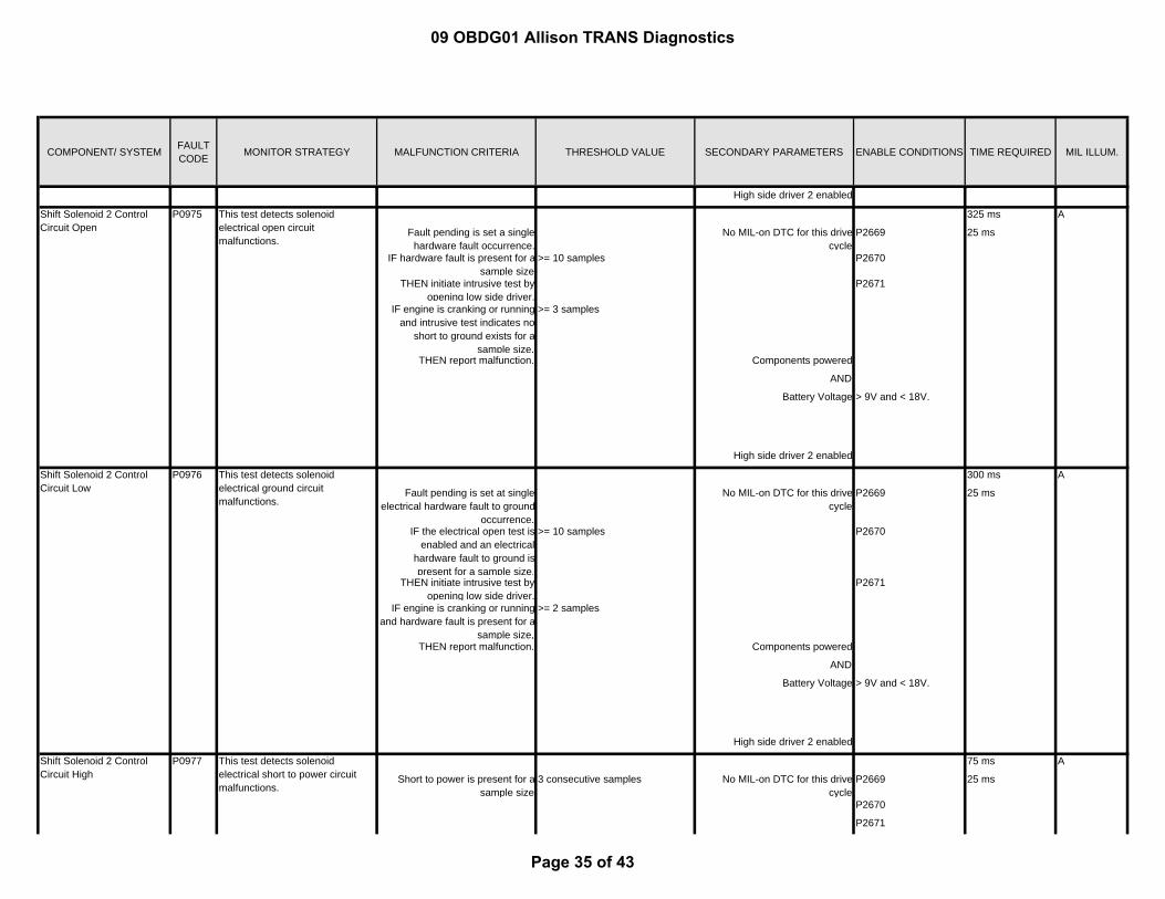
P0976 This test detects solenoid electrical ground circuit malfunctions.
A
Shift Solenoid 2 Control Circuit Open
P0975 This test detects solenoid electrical open circuit malfunctions.
A
Shift Solenoid 2 Control Circuit High
P0977 This test detects solenoid electrical short to power circuit malfunctions.
A
09 OBDG01 Allison TRANS Diagnostics
Page 35 of 43

COMPONENT/ SYSTEM FAULT CODE MONITOR STRATEGY MALFUNCTION CRITERIA THRESHOLD VALUE SECONDARY PARAMETERS ENABLE CONDITIONS TIME REQUIRED MIL ILLUM.
P0977
Components powered
AND
Battery Voltage > 9V and < 18V.
High side driver 2 enabled
250 ms
Fault pending is set a single hardware fault occurrence. If
engine is cranking or running and hardware fault is present for
sample size,
>= 6 samples No MIL-on DTC for this drive cycle
P2669 25 ms
then report malfunction. P2670
P2671
P0979
P0980
Components powered
AND
Battery Voltage > 9V and < 18V.
High side driver 2 enabled
Commanded gear NOT Reverse Trim,
NOT 5th, NOT 6th
75 ms
Short to power is present for a sample size
3 consecutive samples No MIL-on DTC for this drive cycle
P2669 25 ms
P2670
P2671
P0980
Components powered
AND
Battery Voltage > 9V and < 18V.
Shift Solenoid 3 Control Circuit Low
P0979 This test detects solenoid electrical ground circuit malfunctions.
A
Shift Solenoid 3 Control Circuit High
P0980 This test detects solenoid electrical short to power circuit malfunctions.
A
09 OBDG01 Allison TRANS Diagnostics
Page 36 of 43
COMPONENT/ SYSTEM FAULT CODE MONITOR STRATEGY MALFUNCTION CRITERIA THRESHOLD VALUE SECONDARY PARAMETERS ENABLE CONDITIONS TIME REQUIRED MIL ILLUM.
High side driver 2 enabled
Commanded gear NOT Reverse Trim,
NOT 5th, NOT 6th
75 ms
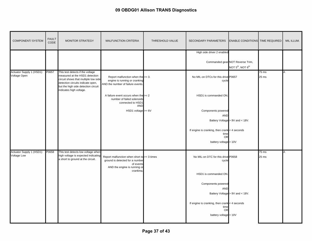
Report malfunction when the engine is running or cranking
AND the number of failure events.
>= 3. No MIL-on DTCs for this drive cycle
P0657 25 ms
A failure event occurs when the number of failed solenoids
connected to HSD1
>= 2 HSD1 is commanded ON.
AND
HSD1 voltage >= 6V Components powered
AND
Battery Voltage > 9V and < 18V.
If engine is cranking, then crank time
< 4 seconds
OR
battery voltage > 10V
75 ms
Report malfunction when short to ground is detected for a number
of events
>= 3 times No MIL-on DTC for this drive cycle
P0658 25 ms
AND the engine is running or cranking.
HSD1 is commanded ON.
Components powered
AND
Battery Voltage > 9V and < 18V.
If engine is cranking, then crank time
< 4 seconds
OR
battery voltage > 10V
Actuator Supply 1 (HSD1) Voltage Open
P0657 This test detects if the voltage measured at the HSD1 detection circuit shows that multiple low side detection circuits indicate open, but the high side detection circuit indicates high voltage.
A
Actuator Supply 1 (HSD1) Voltage Low
P0658 This test detects low voltage when high voltage is expected indicating a short to ground at the circuit.
A
09 OBDG01 Allison TRANS Diagnostics
Page 37 of 43

COMPONENT/ SYSTEM FAULT CODE MONITOR STRATEGY MALFUNCTION CRITERIA THRESHOLD VALUE SECONDARY PARAMETERS ENABLE CONDITIONS TIME REQUIRED MIL ILLUM.
75 ms
During initialization, report malfunction when the number of
failure events
>= 3 times During initialization 25 ms
A failure event occurs when HSD1 voltage
>= 6V
75 ms
Report malfunction when the engine is running or cranking
AND the number of failure events.
>= 3. No MIL-on DTC for this drive cycle
P2669 25 ms
A failure event occurs when the number of failed solenoids
connected to HSD1
>= 2 HSD2 is commanded ON.
AND
HSD1 voltage >= 6V Components powered
AND
Battery Voltage > 9V and < 18V.
If engine is cranking, then crank time
< 4 seconds
OR
battery voltage > 10V
75 ms
Report malfunction when short to ground is detected for a number
of events
>= 3 times No MIL-on DTC for this drive cycle
P2670 25 ms
AND the engine is running or cranking.
HSD2 is commanded ON.
Components powered
AND
Battery Voltage > 9V and < 18V.
If engine is cranking, then crank time
< 4 seconds
P0659 This test detects if the voltage measured at the HSD 1 detection circuit indicates high during initialization (when the circuit is off)
Actuator Supply2 (HSD2) Voltage Low
P2670 This test detects low voltage when high voltage is expected indicating a short to ground at the circuit.
A
A
Actuator Supply2 (HSD2) Voltage Open
P2669 This test detects if the voltage measured at the HSD2 detection circuit shows that multiple low side detection circuits indicate open, but the high side detection circuit indicates high voltage.
A
Actuator Supply 1 (HSD1) Voltage High
09 OBDG01 Allison TRANS Diagnostics
Page 38 of 43
COMPONENT/ SYSTEM FAULT CODE MONITOR STRATEGY MALFUNCTION CRITERIA THRESHOLD VALUE SECONDARY PARAMETERS ENABLE CONDITIONS TIME REQUIRED MIL ILLUM.
OR
battery voltage > 10V
75 ms
During initialization, report malfunction when the number of
failure events
>= 3 times During initialization 25 ms
A failure event occurs when HSD1 voltage
>= 6V
3075 ms
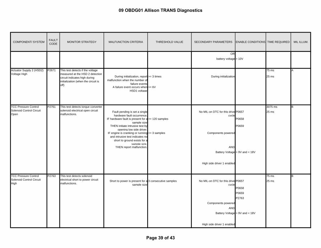
Fault pending is set a single hardware fault occurrence.
No MIL-on DTC for this drive cycle
P0657 25 ms
IF hardware fault is present for asample size
>= 120 samples P0658
THEN initiate intrusive test by opening low side driver.
P0659
IF engine is cranking or running and intrusive test indicates no
short to ground exists for a sample size,
>= 3 samples Components powered
THEN report malfunction. AND
Battery Voltage > 9V and < 18V
High side driver 1 enabled
75 ms
Short to power is present for a sample size
3 consecutive samples No MIL-on DTC for this drive cycle
P0657 25 ms
P0658
P0659
P2763
Components powered
AND
Battery Voltage > 9V and < 18V
High side driver 1 enabled
A
TCC Pressure Control Solenoid Control Circuit Open
P2761 This test detects torque converter solenoid electrical open circuit malfunctions.
B
Actuator Supply 2 (HSD2) Voltage High
P2671 This test detects if the voltage measured at the HSD 2 detection circuit indicates high during initialization (when the circuit is off)
TCC Pressure Control Solenoid Control Circuit High
P2763 This test detects solenoid electrical short to power circuit malfunctions.
B
09 OBDG01 Allison TRANS Diagnostics
Page 39 of 43
COMPONENT/ SYSTEM FAULT CODE MONITOR STRATEGY MALFUNCTION CRITERIA THRESHOLD VALUE SECONDARY PARAMETERS ENABLE CONDITIONS TIME REQUIRED MIL ILLUM.
3050 ms
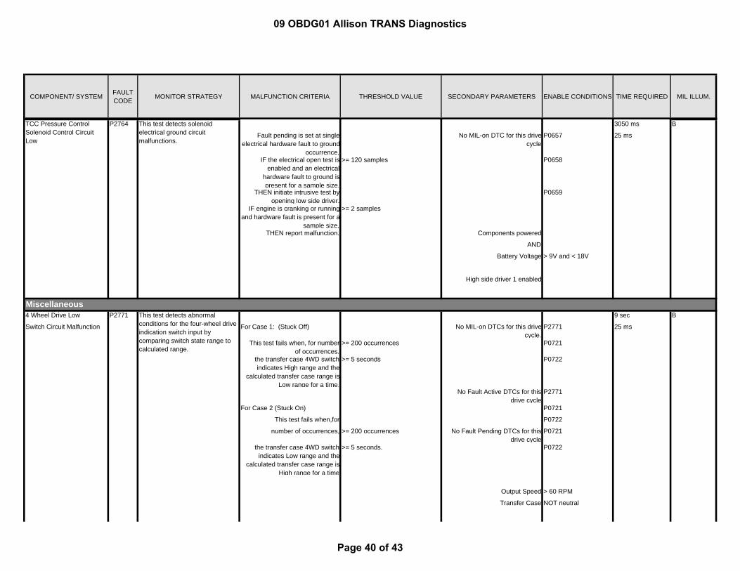
Fault pending is set at single electrical hardware fault to ground
occurrence.
No MIL-on DTC for this drive cycle
P0657 25 ms
IF the electrical open test is enabled and an electrical
hardware fault to ground is present for a sample size,
>= 120 samples P0658
THEN initiate intrusive test by opening low side driver.
P0659
IF engine is cranking or running and hardware fault is present for a
sample size,
>= 2 samples
THEN report malfunction. Components powered
AND
Battery Voltage > 9V and < 18V
High side driver 1 enabled
Miscellaneous4 Wheel Drive Low 9 sec
Switch Circuit Malfunction For Case 1: (Stuck Off) No MIL-on DTCs for this drive cycle.
P2771 25 ms
This test fails when, for number of occurrences,
>= 200 occurrences P0721
the transfer case 4WD switch indicates High range and the
calculated transfer case range is Low range for a time.
>= 5 seconds P0722
No Fault Active DTCs for this drive cycle
P2771
For Case 2 (Stuck On) P0721
This test fails when,for P0722
number of occurrences, >= 200 occurrences No Fault Pending DTCs for this drive cycle
P0721
the transfer case 4WD switch indicates Low range and the
calculated transfer case range is High range for a time
>= 5 seconds. P0722
Output Speed > 60 RPM
Transfer Case NOT neutral
TCC Pressure Control Solenoid Control Circuit Low
P2764 This test detects solenoid electrical ground circuit malfunctions.
B
P2771 This test detects abnormal conditions for the four-wheel drive indication switch input by comparing switch state range to calculated range.
B
09 OBDG01 Allison TRANS Diagnostics
Page 40 of 43
COMPONENT/ SYSTEM FAULT CODE MONITOR STRATEGY MALFUNCTION CRITERIA THRESHOLD VALUE SECONDARY PARAMETERS ENABLE CONDITIONS TIME REQUIRED MIL ILLUM.
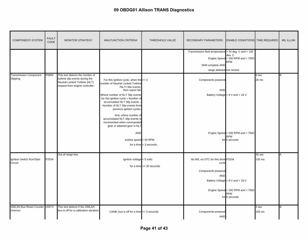
Transmission fluid temperature > 20 deg. C and < 130 deg. C
Engine Speed > 200 RPM and < 7500 RPM
Shift complete AND
range attained not neutral
9 sec
For this ignition cycle, when thenumber of Neutral Locked Turbine
(NLT) Slip events,
>= 3 Components powered 25 ms
then report fail. AND
Where number of NLT Slip events for this ignition cycle = Number of
accumulated NLT Slip events – Number of NLT Slip events from
previous ignition cycles.
Battery Voltage > 9 V and < 18 V
And, where number of accumulated NLT Slip events is incremented when commanded
gear or attained gear is NLT
AND Engine Speed > 200 RPM and < 7500 RPM
turbine speed > 50 RPM for 5 seconds
for a time > 3 seconds.
30 sec
Ignition Switch Run/Start Circuit
P2534 Ignition voltage < 5 volts No MIL-on DTC for this drive cycle
P2534 100 ms
for a time >= 30 seconds
Components powered
AND
Battery Voltage > 9 V and < 18 V
Engine Speed > 200 RPM and < 7500 RPM
for 5 seconds
3 sec
CANB_bus is off for a time >= 3 seconds Components powered 100 ms
AND
Transmission Component Slipping
P0894 This test detects the number of turbine slip events during the Neutral Locked Turbine (NLT) request from engine controller.
B
Out of range low. A
GMLAN Bus Reset Counter Overrun
U0073 This test detects if the GMLAN bus is off for a calibration duration.
B
09 OBDG01 Allison TRANS Diagnostics
Page 41 of 43

COMPONENT/ SYSTEM FAULT CODE MONITOR STRATEGY MALFUNCTION CRITERIA THRESHOLD VALUE SECONDARY PARAMETERS ENABLE CONDITIONS TIME REQUIRED MIL ILLUM.
Battery Voltage > 9 V and < 18 V
Engine Speed > 200 RPM and < 7500 RPM
for 5 seconds
For Case 1:
Case 1 (x out of y): Components powered AND 700 ms
The failure counter increments when a State of Health (SOH)
failure is detected. A SOH failure occurs when message is missing.
When the failure counter is a number of samples
>= 5 samples Battery Voltage > 9 V and < 18 V
out of a number of samples, 7 samples For Case 2:
report fail. Engine Speed > 200 RPM and < 7500 RPM
3.5 seconds
for 5 seconds 100 ms
Case 2 ( intermittent):
Report fail, when the failure counter
> 0 counts Ignition Key State RUN
and number of samples < 5 samples
out of number of samples 7 samples GMLAN message $191 is received from ECM
for 5 consecutive sample windows
Enable criteria met for a time > 3 seconds
Case 1 (PRNDL state is N, P or R):
No MIL-on DTCs for this drive cycle.
P0826
PRNDL state is unchanged P0708 Case 1:
for a time >= 2.5 seconds Components powered 5.5 seconds
AND AND
upshift switch state ON Battery Voltage > 9 V and < 18 V Case 2:
for a time >= 3 seconds. 602.5 seconds
Engine Speed > 200 RPM and < 7500 RPM
Case 2 (PRNDL state is forward range):
for 5 seconds 100 ms
PRNDL state is unchanged
Upshift Switch Circuit P0815 This test detects the upshift switch ON.
C
GMLAN ECM Controller State of Health Failure
U0100 This test detects CAN (GMLAN) bus failures by detecting State of Health failures in GMLAN message $191 from ECM.
B
09 OBDG01 Allison TRANS Diagnostics
Page 42 of 43

COMPONENT/ SYSTEM FAULT CODE MONITOR STRATEGY MALFUNCTION CRITERIA THRESHOLD VALUE SECONDARY PARAMETERS ENABLE CONDITIONS TIME REQUIRED MIL ILLUM.
for a time >= 2.5 seconds
AND
upshift switch state ON
for a time >= 600 seconds.
Case 1 (PRNDL state is N, P or R):
No MIL-on DTCs for this drive cycle.
P0826
PRNDL state is unchanged P0708 Case 1:
for a time >= 2.5 seconds Components powered 5.5 seconds
AND AND
downshift switch state ON Battery Voltage > 9 V and < 18 V Case 2:
for a time. >= 3 seconds. 602.5 seconds
Engine Speed > 200 RPM and < 7500 RPM
Case 2 (PRNDL state is forward range):
for 5 seconds 100 ms
PRNDL state is unchanged
for a time >= 2.5 seconds
AND
downshift switch state ON
for a time >= 600 seconds.
Switch state is ILLEGAL for a time >= 10 seconds. No MIL-on DTCs for this drive cycle.
P0826 10 seconds
Components powered 100 ms
AND
Battery Voltage > 9 V and < 18 V
Engine Speed > 200 RPM and < 7500 RPM
for 5 seconds
Up and Down Shift Switch Circuit
P0826 This test detects upshift/downshift switch circuit at an illegal state.
C
Downshift Switch Circuit P0816 This test detects the downshift switch ON.
C
09 OBDG01 Allison TRANS Diagnostics
Page 43 of 43