
09mn03
62
Control systems and applications V.ARUN KUMAR(09MN03)
description
09mn03
Transcript of 09mn03

Control systems and applications
V.ARUN KUMAR(09MN03)

What is Control? Control is the process of causing a
system variable to conform to some desired value
Types of control Manual control Automatic control

Manual versus Automatic Control Control is the process of causing a system
variable (temperature, position) to conform to some desired value or trajectory, called reference value or trajectory
Example: driving a car implies controlling the vehicle to follow the desired path and arrive safely at a planned destination

Cont..
• If you drive the car yourself, you are performing a manual control of the car. If you design a machine (or use a computer) to do it, then you build an automatic control system

General Structure of Control Systems
Elements in control systems:• System/Plant/Process• Sensors• Actuators• Controllers
Properties of control systems:• Stability• Performance• Robustness

What is Control System? A Control system is an interconnection
of components forming a system configuration that will provide a desired system response.
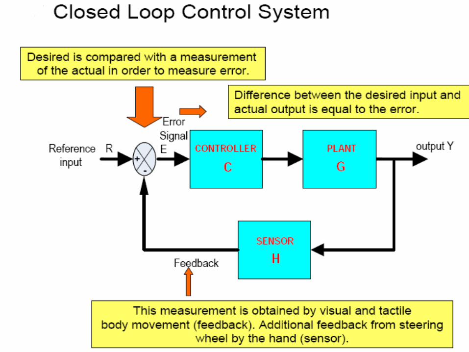
Types of control system Open-loop control system Closed-loop (feedback) control system

Open-loop/Closed-loop Systems• Open Loop

Open-loop/Closed-loop Systems
• Closed-Loop (Feedback system)

Example 1: Car and Driver
• Objective function: To control the direction and speed of the car• Outputs: actual direction and speed of the car• Control inputs: road markings and speed signs• Disturbances: road surface and grade, wind, obstacles• Possible subsystems: the car alone, power steering system, braking system, . . .

Functional Block Diagram and Time Responses

Time response


• Original system: the antenna with electric motor drive systems.
• Control objective: To point the antenna in a desired reference direction.
• Control inputs: Drive motor voltages.
• Outputs: The elevation and azimuth of the antenna.
• Disturbances: Wind, rain, snow.
Example 2:Antenna Positioning Control System

Position control system
a. system concept
b. detailed layout

Position control system
c. schematic;
d. functional block diagram

Functional Block Diagram of antenna control system

System, plant or process (to be controlled) Actuators (converts the control signal to a power
signal) Sensors (provides measurement of the system
output) Reference input (represents the desired output) • Error detection (forms the control error) • Controller (operates on the control error to form the
control signal, sometimes called compensators)
Control System Components

• Analysis – Given a system, to analyze the system’s 1. Stability 2. Dynamic characteristics 3. Steady-state characteristics
• Design (Synthesis) – Design a new system or compensate (modify) an existing system for
1. Stability guarantee 2. Good dynamic performance 3. Satisfactory steady-state performance
Basic Integrants in Control Systems

Modeling Laplace transforms and transfer functions, state-space model • Time-domain method – Time-domain performance specifications – Stability, transient and steady-state responses • Complex-domain method Root locus method for analysis and design of control systems • Frequency-domain method – Frequency-domain performance specifications – Nyquist plots and Bode diagrams for analysis and design of control systems
Methods in Analysis and Design

Control System Design Objectives• Primary objectives: 1. Dynamic stability 2. Accuracy 3. Speed of response
• Additional considerations: 4. Robustness (insensitivity to parameter variation) 5. Cost of control 6. System reliability

Control System Design Steps

Test waveforms used in control systems
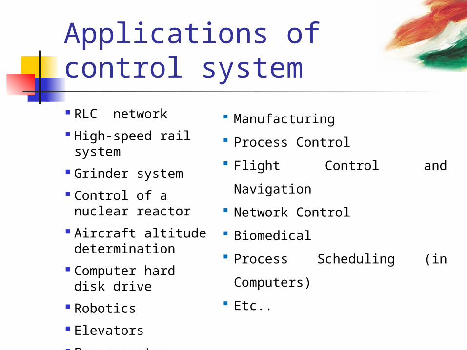
Applications of control system RLC network High-speed rail
system Grinder system Control of a nuclear reactor Aircraft altitude determination Computer hard disk drive Robotics Elevators Power system
Manufacturing Process Control Flight Control and Navigation Network Control Biomedical Process Scheduling (in
Computers) Etc..

Latest trend in control system SCADA implementation in various
fields In case of renewable energy
system SCADA has been successfully implemented in solar and wind power.

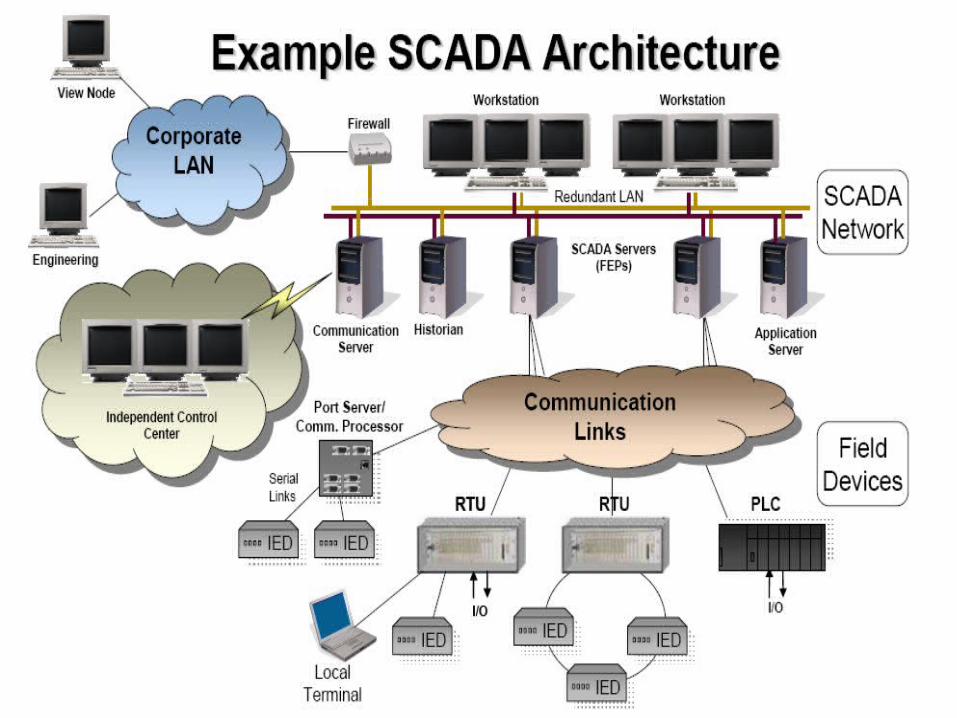
SCADA SCADA stands for supervisory
control and data acquisition It generally refers to an industrial
control system: a computer system monitoring and controlling a process.

Layers of SCADAThere are three layers SCADA master communication media local control system.


SCADA using internet communication

Physical link in SCADA System from site to site

Data storage using GPS and control

Snap shot of SCADA monitor


SCADA in solar power system

Voltage variation in solar system


An example for solar power system


SCADA SCREEN

SCADA monitoring

SCADA control system in Delhi

SCADA IN WIND POWER


CONTROLLING THROUGH PLC


IMPLEMENTED SCADA SYSTEM IN WIND POWER SYSTEM

54
Central GeneratingStation
Step-Up Transformer
DistributionSubstation
ReceivingStation
DistributionSubstation
DistributionSubstation
Commercial
Industrial Commercial
Gas Turbine
DieselEngine
Cogeneration
CogenerationTurbine
Fuel cell
Micro-turbine
Wind Power
Residential
Storage
Photovoltaic systems
Power System Infrastructure using SCADA
To maintain power system reliability, need to manage both the Power System Infrastructure and its supporting Information Infrastructure

Snap shots of SCADA screen

Communication server
Time & data recording

Variation of solar voltagePresent alarms
Processing alarms
Processed alarms
Different colour codes

Solar 1
Solar 2
wind
hydro

To supervisor
Alarm details
AUTOMATIC SMS GENERATOR

Advantages of SCADA Low capital investment for components Maintenance is less Easy to install and maintain Time of action is less Wide range of monitoring possible Reliable Automation makes easy to rectify faults Communication is faster
Reference http://www.empire-cat_com http://www.wikipedia.com/ http://www.renewablesources.com/ http://www.MoxaApplication.com/W
ind Farm System/ http://www.google.com/scada/ http://www.powermin.nic.in/

Thank you


