090108 P104 Injection molding - uni- · PDF fileMSci PolySci P104 – Injection molding 2...
12
MSci PolySci-Lab Modul P104 P P P o o o l l l y y y m m m e e e r r r m m m a a a t t t e e e r r r i i i a a a l l l i i i e e e n n n & & & P P P o o o l l l y y y m m m e e e r r r t t t e e e c c c h h h n n n o o o l l l o o o g g g i i i e e e Injection molding 1 Introduction Figure 1: Injection molding machine Arburg 320 S (Neue Materialien Bayreuth GmbH) About 60 % of all polymer-processing machines are injection molding machines for which reason injection molding is a very important processing strategy for thermoplastics. This way it is possible to produce parts with a weight in the range from less than one mg to more than 100 kg. Minor further treatment after processing is the main advantage. Figure 1 and 2 show some typical injection molding machines. Figure 2: Injection molding machines for several applications and material systems (Krauss-Maffei; Sumitomo-Demag; Ferromatik Milacron; Engel)
Transcript of 090108 P104 Injection molding - uni- · PDF fileMSci PolySci P104 – Injection molding 2...

MSci PolySci-Lab Modul P104
PPP ooo lll yyy mmm eee rrr mmm aaa ttt eee rrr iii aaa lll iii eee nnn&&&
PPP ooo lll yyy mmm eee rrr ttt eee ccc hhh nnn ooo lll ooo ggg iii eee
Injection molding
1 Introduction
Figure 1: Injection molding machine Arburg 320 S (Neue Materialien Bayreuth GmbH) About 60 % of all polymer-processing machines are injection molding machines for which reason injection molding is a very important processing strategy for thermoplastics. This way it is possible to produce parts with a weight in the range from less than one mg to more than 100 kg. Minor further treatment after processing is the main advantage. Figure 1 and 2 show some typical injection molding machines.
Figure 2: Injection molding machines for several applications and material systems (Krauss-Maffei;
Sumitomo-Demag; Ferromatik Milacron; Engel)

MSci PolySci P104 – Injection molding 2
Figure 3 shows schematically the injection molding process including the three main steps plasticizing, injection and demolding.
a) The turning screw conveys the granulate from the feed hopper through the screw
channels to the screw tip – Plasticizing b) The mold closes, the injection unit moves forward to the sprue bush, the screw
presses the molten polymer like a piston into the mold – Injection c) The ejectors demold the frozen molding from the open mold, the screw conveys new
material to the screw tip, the injection unit moves backward – Demolding Figure 3: Process description of injection molding Like in all types of processing methods the output of parts per time unit (cycle time) is crucial for productivity. The cycle time depends particularly on the cooling time. The cooling time increases proportionally with the wall thickness in second power. This is of high importance in molding parts with high wall thicknesses. Characteristics of injection molding are:
Direct processing from bulk material to finished part No or minor post-processing Fully automated process High reproducibility High quality of molded parts
2 Literature
1. Michaeli, W., Einführung in die Kunststoffverarbeitung, Hanser-Verlag München 1999.
2. Menges, G., Mohren, P., Spritzgießwerkzeuge, Hanser-Verlag München 1998.
3. Johannaber, F., Michaeli, W., Handbuch Spritzgießen, Hanser-Verlag München 2001.

MSci PolySci P104 – Injection molding 3
3 Keyword Glossary
Barrel Zylinder Cavity Formnest Clamping force Schließkraft Clamping unit Schließeinheit Compression section Kompressionszone Compression stage Kompressionsphase Control cabinet Schaltschrank Cooling time Kühlzeit Cycle time Zykluszeit Demolding Entformen Ejectors Auswerfer Ejector bolts Auswerferbolzen Ejector pins Auswerferstifte Ejector plate Auswerferplatte Feed hopper Einfülltrichter Feed section Einzugszone Feeding stroke Dosierweg Flange Flansch Gate Anschnitt, Anguss Heating equipment Temperiergerät / -einheit Holding pressure Nachdruck Hydraulic clamping system Hydraulische Schließeinheit Injection Einspritzen Injection pressure Einspritzdruck Injection speed / velocity Einspritzgeschwindigkeit Injection stage Einspritzphase Injection unit Einspritzeinheit Machine bed Maschinenbett Metering Dosieren Metering section Austragszone Metering stroke Dosierhub Mold (Spritzgieß-) Werkzeug Molding Formteil Moving (clamping) platen Bewegliche Aufspannplatte Nozzle Düse Piston Kolben Plasticizing Plastifizieren Plasticizing cylinder Plastifizierzylinder Plasticizing unit Plastifiziereinheit Pre-drying Vortrocknen Primary shaping Urformen Reciprocating screw Schneckenkolben Residual melt cushion Restmassepolster

MSci PolySci P104 – Injection molding 4
Runner system Angusssystem Screw Schnecke Screw channels Schneckengänge Screw tip Schneckenspritze Shrinkage Schwindung Shrink mark Einfallstelle Slide bar Schieber Sprue bush Angussbuchse Stationary claming plate Feste Aufspannplatte Suction valve Ansaugventil Switching point Umschaltpunkt Three-zone screw Dreizonenschnecke Tie bar Holm Toggle Kniehebel

MSci PolySci P104 – Injection molding 5
4 Injection molding machine
Injection molding machines are normally general-purpose machines. DIN 24450 defines the task as follows: Discontinuous production of moldings from primarily macromolecular substances, whereas primary shaping is performed under pressure. The different devices of an injection molding machines are depicted in figure 4:
Figure 4: Setup of an injection molding system
4.1 Injection / Plasticizing unit
The plasticizing unit melts, homogenizes, conveys, meters and injects the polymer into the mold. Thus the injection unit has two main tasks: On one hand it plasticizes the polymer and on the other hand it injects the melt into the mold. Standard machines have typically reciprocating screws, which means the screw acts also as an injection piston. Nowadays there are also approaches existing which separate plasticizing and injection unit. Common screws for injection molding consist of three zones:
Feed section Compression section Metering section
The screw rotates in a heated barrel and a feed hopper delivers granulate or powder into the barrel. Usually the injection unit is mounted flexibly on the machine bed. Barrel, screw and nozzle are exchangeable. In doing so the injection unit is adaptable to the type of polymer and the shot volume.

MSci PolySci P104 – Injection molding 6
4.2 Clamping unit
The clamping unit resembles to a horizontal press. The moving platen slides on four bars and the halves of the mold are mounted on both platens. Common drive systems are working:
Hydraulically o Hydraulically activated toggle o Clamping by a hydraulic cylinder
Electrically
The so-called full electrical injection molding machines are driven exclusively by servo-drives. The position detection occurs directly at the motor axes. Thus very short reaction times are possible. In comparison to hydraulic machines the full electrical principle exhibits different advantages:
o Higher precision due to fast reaction times of the electro-mechanical drives o Energy saving by higher efficiency o Low maintenance of electro-mechanical drives o High reproducibility by direct mechanical connection of motors and axes o Higher output due to parallel operation mode o No use of hydraulic oil results in cleaner production
Hydraulic driven toggles are normally used for smaller and medium machine sizes, Figure 5.
Figure 5: Toggle clamping system

MSci PolySci P104 – Injection molding 7
Advantageous are the force-speed-characteristics of these clamping units. This means the course of force depends on the position of the toggle or the course of the speed of the platens depends on this position respectively. There from results a high moving speed of the platens combined with low clamping forces and a slow clamping speed with high clamping forces in the end of clamping. On the other side breakages of the tie bars are possible. Further disadvantages are permanent deformation of the mold after poor adjustment of the toggle and the high maintenance. When using a hydraulic clamping system no breakages of the tie bars will occur. Hence these systems achieve more and more acceptance, figure 6.
Figure 6: Fully hydraulic clamping system Advantages of fully hydraulic systems are: higher precision, variable positioning, no unacceptable mold deformation and no breakages of tie bars. Disadvantages are slower clamping speed, minor stiffness of the clamping unit caused by the high compliance of the oil medium and the high energy demand.
4.3 Machine bed and control
The plasticizing and clamping unit are fixed in the machine bed. Furthermore it contains the reservoir for the hydraulic oil and the hydraulic drives. Sometimes also the machine controls are mounted in the machine bed. The control cabinet contains all the instruments, the electrical circuit elements, controllers and actuators and the power supply. Modern machines provide the possibility for information input by a keyboard and screen dialog. The integrated processor cares for the sequence control, monitors process and production data, saves the data and keeps records of the process.
MSci PolySci P104 – Injection molding 8
4.4 Mold
Since it is constructed for each molded part individually, the mold for injection molding belongs not directly to the machine. It contains two main parts minimum, which are mounted on the clamping plates. The maximum mold size depends on the size of the clamping plates. Thereby the distance between the adjacent tie bars limits the size of the mold. Generally the mold consists of the following elements:
Plate with cavity Runner system Heating system Ejector system
These elements fulfill the following tasks:
Melt intake and spreading Drawing of the pattern Quenching of the melt Demolding
The costs for an injection molding tool are very high from averagely 5.000 € up to 500.000 € for complicated multi-part molds with slide bars. Hence the fabrication of such molds is only profitable, when high quantities of molded parts are expected.
4.5 Demolding system
The demolding system with its ejector plates and pins is a moving element of the mold. After finishing the cooling time the clamping unit opens the mold and a hydraulic cylinder moves the ejector bolts towards the molding in order to push it out of the cavity by the ejector pins. Frequently also compressed air is employed supportingly.
4.6 Runner system
During injection the melt is pressed through the runner system and the gate into the cavity, where the final part is going to be molded. Therefore different systems are in use, in order to guarantee a sufficient filling dependent on the molding geometry. It is also possible to apply a certain temperature to the runner system. By using more than one cavity per mold the efficiency is improved. This case the main runner channel coming from the nozzle splits into several channels, which deliver the melt to each single cavity. The balance of the runner system is of special importance. That means that the melt has to fill each cavity at the same time. Furthermore it is crucial that the melt has the same pressure and temperature when entering the cavities. Thus a constant quality of the moldings is assured.

MSci PolySci P104 – Injection molding 9
5 Process flow of injection molding
The procedure of injection molding is depicted in figure 7.
Figure 7: Injection molding cycle It is clear that all procedure steps of injection molding take place one after another except for the important cooling stage, which overlaps with the holding pressure, the backward movement of the plasticizing unit, metering and plasticizing stage. The machine control coordinates each process step and repeats it every injection molding cycle. To achieve a high output and hence a high process efficiency the cycle time should be kept as short as possible.
5.1 Metering
The screw, which rotates in the plasticizing cylinder, conveys the melt from the hopper to the end of the screw. This way the material is going to be densified and brought into a molten stage. While the screw conveys the melt, the screw moves backward because the delivered material conglomerates at the screw tip. While moving backwards a definite pressure is applied to the screw, which is called back pressure. In doing so the screw has to convey against this pressure and the homogenization and the dissipation heating improves. This back pressure is adjustable.

MSci PolySci P104 – Injection molding 10
At a certain screw position the metering stops, because the mass of melt for filling the whole cavities is reached. The position of the screw or the way the screw moves backward respectively represents the metering volume and is called feeding stroke or metering stroke. Both parameters have to be adjusted for each new molding process.
5.2 Injection
During injection the screw moves forward without rotating and injects the metered material through the nozzle into the mold. In doing so the screw acts like an injection piston. A residual melt cushion remains in front of the screw for applying the following holding pressure. The maximum injection pressure is a prefixed parameter and an upper limit for the applied injection pressure. Another prefixed parameter is the injection speed. However it is variable during injection stage. It is also possible to apply an increasing or decreasing velocity profile during injection and holding pressure stage.
5.3 Melt flow in the cavities during injection
The melt flow can be divided into three stages, depicted in Figure 8: A) Injection stage B) Compression stage C) Holding pressure
Figure 8: Cavity pressure during mold filling During injection stage the mold is going to be filled volumetrically. Afterwards the velocity slows down and compression takes place. For densification more melt is conveyed into the mold, while the pressure in the cavity rises rapidly and steeply. When reaching a certain pressure value the holding pressure stage begins. When switching too late from compression

MSci PolySci P104 – Injection molding 11
to holding pressure stage a high peak pressure arises in the melt that exhibits still a very low viscosity. Thus overmolding becomes possible. While cooling down the polymer shrinkage occurs. Hence more molten material has to be conveyed into the cavity during holding pressure stage in order to keep the volume of the molding constant. This stage is finished when the gate freezes. The switching point from compression to holding pressure is of high importance. When switching too early the density of the molding is too low and shrink marks are visible on the surface.
5.4 Cooling stage
Cooling begins with injection and ends with demolding. Afterwards the molding has to exhibit a certain temperature and enough stability. Cooling channels in the mold nearby the cavities support cooling. A cooling medium mostly oil or water flows through the channels. Its temperature is set at a definite value and controlled by a cooling aggregate.
MSci PolySci P104 – Injection molding 12
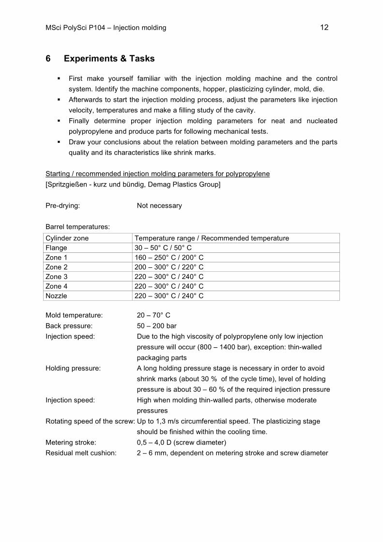
6 Experiments & Tasks
First make yourself familiar with the injection molding machine and the control system. Identify the machine components, hopper, plasticizing cylinder, mold, die.
Afterwards to start the injection molding process, adjust the parameters like injection velocity, temperatures and make a filling study of the cavity.
Finally determine proper injection molding parameters for neat and nucleated polypropylene and produce parts for following mechanical tests.
Draw your conclusions about the relation between molding parameters and the parts quality and its characteristics like shrink marks.
Starting / recommended injection molding parameters for polypropylene [Spritzgießen - kurz und bündig, Demag Plastics Group] Pre-drying: Not necessary Barrel temperatures: Cylinder zone Temperature range / Recommended temperature Flange 30 – 50° C / 50° C Zone 1 160 – 250° C / 200° C Zone 2 200 – 300° C / 220° C Zone 3 220 – 300° C / 240° C Zone 4 220 – 300° C / 240° C Nozzle 220 – 300° C / 240° C Mold temperature: 20 – 70° C Back pressure: 50 – 200 bar Injection speed: Due to the high viscosity of polypropylene only low injection
pressure will occur (800 – 1400 bar), exception: thin-walled packaging parts
Holding pressure: A long holding pressure stage is necessary in order to avoid shrink marks (about 30 % of the cycle time), level of holding pressure is about 30 – 60 % of the required injection pressure
Injection speed: High when molding thin-walled parts, otherwise moderate pressures
Rotating speed of the screw: Up to 1,3 m/s circumferential speed. The plasticizing stage should be finished within the cooling time.
Metering stroke: 0,5 – 4,0 D (screw diameter) Residual melt cushion: 2 – 6 mm, dependent on metering stroke and screw diameter