09-Circuit Theorems Overview Introduction - Henry Louie, PhD
43
09-Circuit Theorems Text: 4.1 – 4.3, 4.8 ECEGR 210 Electric Circuits I
Transcript of 09-Circuit Theorems Overview Introduction - Henry Louie, PhD

09-Circuit Theorems Text: 4.1 – 4.3, 4.8
ECEGR 210
Electric Circuits I
Overview
• Introduction
• Linearity
• Superposition
• Maximum Power Transfer
Dr. Louie 2

Introduction
• Nodal and mesh analysis can be tedious to apply to large circuits, especially with multiple sources
• Linearity of the circuits considered can be exploited to simplify analysis
Dr. Louie 3

Linearity
• Circuits considered in the this class are linear
• An equation f(x) or system is linear iff
Homogeneity: f(ax) = af(x)
Additivity: f(x + y) = f(x) + f(y)
Dr. Louie 4

Linearity
• Is f(x) = 2x + 1 linear?
• Check homogeneity: f(ax) = af(x)
• Check additivity : f(x + y) = f(x) + f(y)
• No. This is an affine function
Dr. Louie 5
x
f(x) 2ax 1 a(2x 1)
2(x y) 1 2x 1 2y 1

Linearity
• What about Ohm’s Law (V=IR)? Let I be the argument so that f(x) = V(I)
• Check homogeneity: f(ax) = af(x)
• Check additivity: f(x + y) = f(x) + f(y)
• Yes. A circuit is linear if it consists only of linear elements, linear dependent sources and independent sources
Dr. Louie 6
aIR a(IR)
a b a b(I I )R I R I R

Linearity
• What about P=IV?
Careful. V = IR, so P = I2R
• Check homogeneity: f(ax) = af(x)
• Check additivity: f(x + y) = f(x) + f(y)
• No. The power dissipated by a resistor is not linear.
Dr. Louie 7
2 2(aI) R aI R
2 2 2
1 2 1 2(I I ) R I R I R

Significance of Linearity
• The mesh currents for the shown circuit can be written as (by inspection):
Dr. Louie 8
1 2 2 1 1 2
2 2 3 4 2 2
R R R i V V
R R R R i V
A (matrix)
1 1 2
2 2
1 1 1 2
2 2
i V V
i V
i V V
i V
A
A
+
-
+
- V1 V2
R1
R2
R3
R4
i1 i2
Solving for i1, i2

Significance of Linearity
• Observing that:
Dr. Louie 9
+
- V1
R1
R2
R3
R4
i1 i2
1 1 1 2 1 1 21
2 2 2
i V V 0 VV 0
i V V0
A A A
+
- V2
R1
R2
R3
R4
i1 i2
We can solve two “easier” circuits, and add the results!
Significance of Linearity
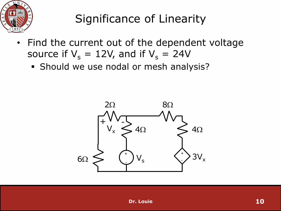
• Find the current out of the dependent voltage source if Vs = 12V, and if Vs = 24V
Should we use nodal or mesh analysis?
Dr. Louie 10
+
-
+
-
2W
6W
4W
8W
4W
3Vx Vs
Vx + -

Significance of Linearity
• since Vs = 12V
Dr. Louie 11
+
-
+
-
2W
6W
4W
8W
4W
3Vx Vs
i1 i2
1 2 s
1 2 x
x 1
0 12i 4i V (mesh 1)
0 4i 16i 3V (mesh 2)
v 2i
Vx + -

Significance of Linearity
Vs = 12V
Dr. Louie 12
+
-
+
-
2W
6W
4W
8W
4W
3Vx Vs
i1 i2
1 2 s
1 2
1 2
1 2
2 s
s2
0 12i 4i V
0 10i 16i
adding...
2i 12i 0
i 6i
via substitution
76i V 0
V 12i 0.158A
76 76
Vx + -
Significance of Linearity
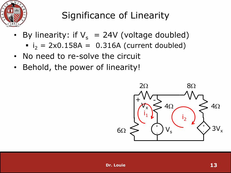
• By linearity: if Vs = 24V (voltage doubled)
i2 = 2x0.158A = 0.316A (current doubled)
• No need to re-solve the circuit
• Behold, the power of linearity!
Dr. Louie 13
+
-
+
-
2W
6W
4W
8W
4W
3Vx Vs
i1 i2
Vx + -

Superposition
• One of the most important circuit analysis benefits of linearity is that superposition can be applied
• Very useful for circuits with multiple independent sources
• Basic idea: analyze the circuit considering only one source at a time, and sum the results once all sources have been considered
Valid for all circuit analysis techniques: Nodal, mesh, Ohm’s Law, etc.
Dr. Louie 14

Superposition
• Simple example with V1 = 10V, V2 = 15V
• Find I
Dr. Louie 15
+
-
+
- V1
5W V2
I
1 2V V
I 1AR

Superposition
• Now solve using superposition
• Consider V1 only
Remove contribution from V2 (set source to 0, a short circuit)
IV1 = 2A
Dr. Louie 16
+
- V1
5W V2 = 0
I

Superposition
• Consider V2 only
Remove contribution from V1 (set source to 0, a short circuit)
IV2 = -3A
Dr. Louie 17
+
- V1 = 0
5W V2 = 15
I

Superposition
• Combining
I = IV2 + IV2 = -1A
Same result as solving the circuit simultaneously
Dr. Louie 18

Superposition
• Analyze circuit with only one independent source at a time
• Independent voltage sources are ignored by replacing them with a short (voltage source where Vs = 0)
• Independent current sources are ignored by replacing them with an open circuit (current source where Is = 0)
• Dependent sources are not ignored
• Sum individual results to analyze circuit
Dr. Louie 19

Example
• Find VR using superposition.
Dr. Louie 20
+
- 6V
8W
4W
+
- VR 3A

Example
• Consider the voltage source first. Set current source to 0A (open circuit)
• By KVL:
12i1 - 6 = 0
i1 = 0.5A
V1 = 2V (VR due to voltage source)
Dr. Louie 21
+
- 6V
8W
4W
+
- VR 3A
+
- 6V
8W
4W +
- V1 i1

Example
• Now consider the current source. Set voltage source to 0V (short circuit)
• By current division:
i2 = (3x8)/(12) = 2A
V2 = 8V (VR due to current source)
Dr. Louie 22
+
- 6V
8W
4W +
- VR 3A
8W
4W +
- V2 3A i2

Example
• Now sum results:
VR = V1 + V2 = 10V
• Note:
iR = i1 + i2 = 2.5A
PR = iR 2R = (i1 + i2 )
2R =31.25W
Any power calculations must be done after all sources considered
Dr. Louie 23
2 2
R 1 2P P P

Example
• Use superposition to find Vx
Dr. Louie 24
20W
4W
+
- Vx 4A
+
- 20V 0.1Vx

Dr. Louie 26

Example
• First consider voltage source.
• Use nodal analysis
Trying to find node voltage
Only one node with unknown voltage
Many elements in parallel
Dr. Louie 28
20W
4W
+
- Vx1
+
- 20V 0.1Vx1
i1 i2

Example
• KCL of node
Dr. Louie 29
x1 1 2
x1 x1x1
x1 x1 x1
x1
i i i
via substitution:
V 20 V0.1V
4 20
V 0.4V 0.2V 4
V 5V
20W
4W
+
- Vx1
+
- 20V 0.1Vx1
i1 i2
ix1

Example
• Now consider current source.
• Rearrange parallel elements for clarity
• Use nodal analysis
Trying to find node voltage
Only one node with unknown voltage
Many elements in parallel
Dr. Louie 30
20W 4W
+
- Vx 0.1Vx 4A
One node

Example
• Now consider current source:
Dr. Louie 31
x2 20 x2
x2 x2x2
x2 x2 x2
x2
4 +0.1V i i
via substitution:
V V4 +0.1V
20 4
4 0.05V 0.25V 0.1V
V 20V
20W 4W
+
- Vx 0.1Vx 4A
One node

Example
• Summing results:
Vx = Vx1 + Vx2 = 25V
Dr. Louie 32

Significance of Linearity
• Consider past example
Dr. Louie 33
1 2 2 1 1 2
2 2 3 4 2 2
R R R i V V
R R R R i V
A (matrix)
+
-
+
- V1 V2
R1
R2
R3
R4
i1 i2
Significance of Linearity
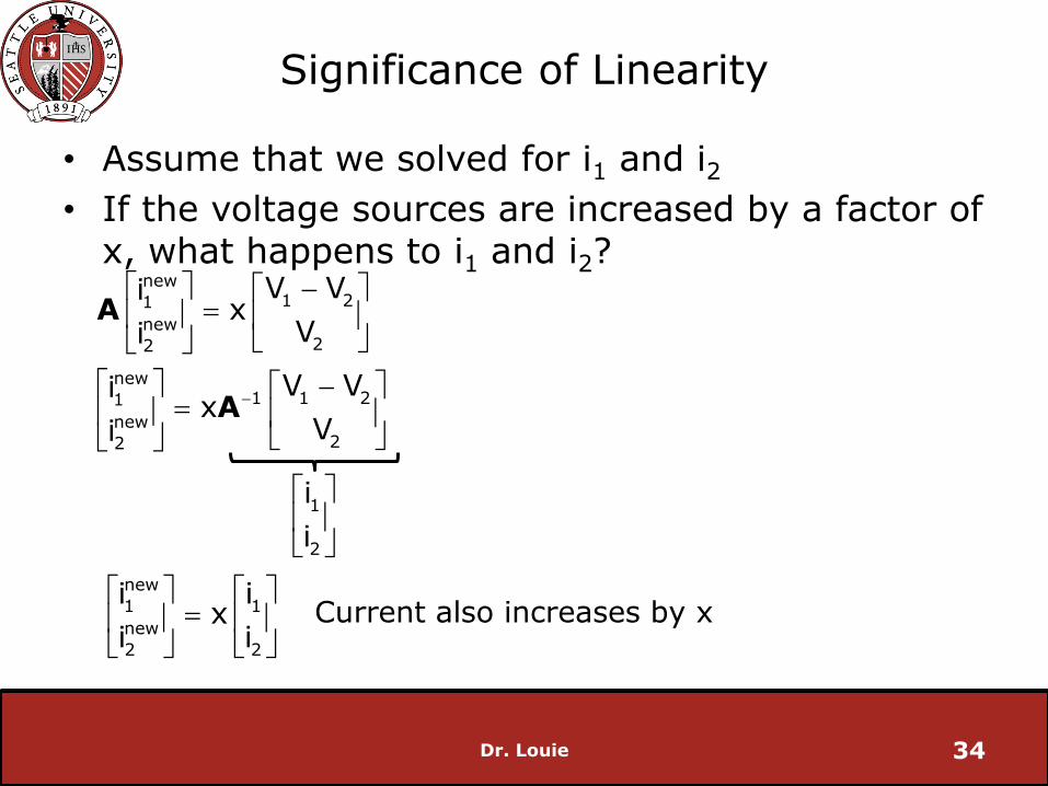
• Assume that we solved for i1 and i2
• If the voltage sources are increased by a factor of x, what happens to i1 and i2?
Dr. Louie 34
new1 21
new22
new1 1 21
new22
V Vix
Vi
V Vix
Vi
A
A
1
2
i
i
new
1 1
new
2 2
i ix
i i
Current also increases by x
Significance of Linearity
• If all the voltages are proportionally increased/decreased, then all current will also proportionally increase/decrease
What happens if all the resistances are proportionally changed?
• Useful if you have already solved the circuit and want to examine how changes will affect the solution
Dr. Louie 35

Maximum Power Transfer
• Often interested in designing a circuit so that the maximum power is delivered (transferred) to a load
• Consider an 11V battery connected to a heater by way of a cable
• What resistance should Rload be to maximize the power it consumes?
Dr. Louie 36
+
- Vs
Rs = 5W
Rload = ?

Maximum Power Transfer
• Idea: try a small resistance in order to increase current (P = I2R)
Let Rload = 0.5W
• Compute power to the load resistor and power consumed by the cable
Dr. Louie 37
+
- Vs
Rs = 5W
Rload = 0.5W
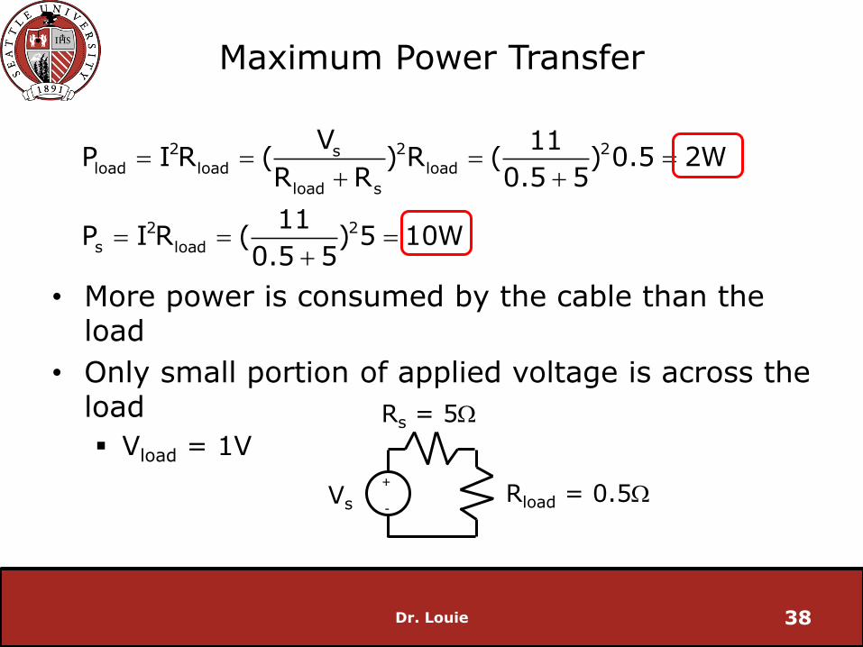
Maximum Power Transfer
• More power is consumed by the cable than the load
• Only small portion of applied voltage is across the load
Vload = 1V
Dr. Louie 38
+
- Vs
Rs = 5W
Rload = 0.5W
2 2 2sload load load
load s
2 2
s load
V 11P I R ( ) R ( ) 0.5 2W
R R 0.5 5
11P I R ( ) 5 10W
0.5 5
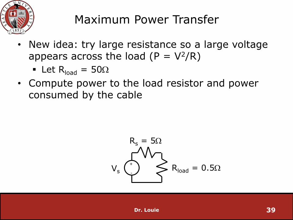
Maximum Power Transfer
• New idea: try large resistance so a large voltage appears across the load (P = V2/R)
Let Rload = 50W
• Compute power to the load resistor and power consumed by the cable
Dr. Louie 39
+
- Vs
Rs = 5W
Rload = 0.5W

Maximum Power Transfer
• More power is consumed by the cable than the load
• Small amount of current flows
I = 0.2A
Dr. Louie 40
+
- Vs
Rs = 5W
Rload = 50W
2 2
load load
2 2
s load
11P I R ( ) 50 2W
5 50
11P I R ( ) 5 10W
5 50
Maximum Power Transfer
• Trade-off between voltage across load and current through load resistor
• Try Rload = Rs
Dr. Louie 41

Maximum Power Transfer
• Power to load is increased
Vload = 5.5V
I = 1.1A
Dr. Louie 42
+
- Vs
Rs = 5W
Rload = 5W
2 2
load load
2 2
s load
11P I R ( ) 5 6.05W
5 5
11P I R ( ) 5 6.05W
5 5

Maximum Power Transfer
• Maximum power transfer occurs when Rload = Rs
• Load and source (with series impedance) are said to be “matched”
• Observations
Voltage across load is one half applied power
Relationship between Rload and Pload must be non-linear
Dr. Louie 43

Maximum Power Transfer
• Proof:
Dr. Louie 44
2 2sload load load
load s
load
load
2 2
load s s load
2 3
load load s load s
2load load s loads 3
load load s
load s
VP I R ( ) R
R R
dPat maximum power transfer 0
dR
solving
dP V 2V R=
dR (R R ) (R R )
dP R R 2R=V 0
dR (R R )
therefore
R R

Maximum Power Transfer
Dr. Louie 45
0 5 10 15 20 25 30 35 40 45 500
1
2
3
4
5
6
7
RLoad
(W)
Pow
er
(W)
Rload
too large Rload
too small