08TS0104 Rev. 00 - IEEEewh.ieee.org/conf/tdc/Ronstrom_08TS0104_Rev_00.pdfStep 3. Switching in a 50...
14
1 © ABB Grid Systems - HVDC 8 May 2008 www.abb.com/hvdc VSC HVDC – A Powerful Stand-by Black Start Facility IEEE PES 2008 Leif Ronström, speaker Ying-Jiang Häfner Hugo Duchen Michael Karlsson Bernt Abrahamsson ABB AB, HVDC, Ludvika, Sweden © ABB -2 Summary Basic HVDC Estlink, a VSC HVDC link Black Start, a feature of Estlink Control modes Full-scale Black-start tests in Estonian grid Conclusions
Transcript of 08TS0104 Rev. 00 - IEEEewh.ieee.org/conf/tdc/Ronstrom_08TS0104_Rev_00.pdfStep 3. Switching in a 50...

1
©AB
BG
rid S
yste
ms
-HVD
C8
May
200
8
www.abb.com/hvdc
VSC HVDC –A Powerful Stand-by Black Start FacilityIEEE PES 2008
Leif Ronström, speakerYing-Jiang Häfner
Hugo DuchenMichael Karlsson
Bernt AbrahamssonABB AB, HVDC, Ludvika, Sweden
©AB
B -2
Summary
Basic HVDC
Estlink, a VSC HVDC link
Black Start, a feature of Estlink
Control modes
Full-scale Black-start tests in Estonian grid
Conclusions

2
©AB
B -3
Thyristor equipped HVDC system
6-pulse rectifierbridge
Current source converters
Need live network on both sides
Delay angle α increased Reduced DC Voltage
Ud
6-pulse inverterbridge
Star
winding
0
Id
∼P
©AB
B -4
HVDC Light® – Voltage Source Converter technology by ABB
IGBT equipped HVDC system – VSC HVDC
AC harmonic filters
DC capacitorsIGBT converter valves
Phase reactors
Cables
PWM Switched voltage
After filtering
- No AC network needed- AC voltage is createdfrom DC by PWM control- DC voltage source is the DC capacitance
3
©AB
B -5
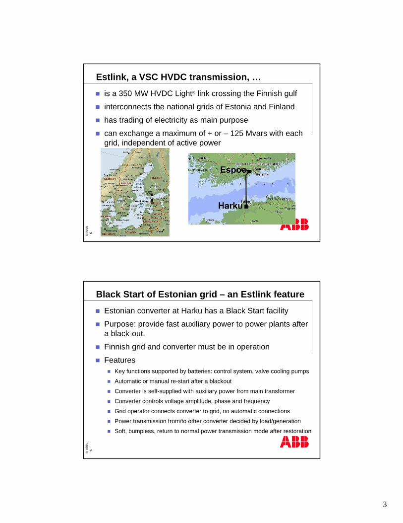
Estlink, a VSC HVDC transmission, …is a 350 MW HVDC Light® link crossing the Finnish gulf
interconnects the national grids of Estonia and Finland
has trading of electricity as main purpose
can exchange a maximum of + or – 125 Mvars with each grid, independent of active power
©AB
B -6
Black Start of Estonian grid – an Estlink featureEstonian converter at Harku has a Black Start facility
Purpose: provide fast auxiliary power to power plants after a black-out.
Finnish grid and converter must be in operation
FeaturesKey functions supported by batteries: control system, valve cooling pumps
Automatic or manual re-start after a blackout
Converter is self-supplied with auxiliary power from main transformer
Converter controls voltage amplitude, phase and frequency
Grid operator connects converter to grid, no automatic connections
Power transmission from/to other converter decided by load/generation
Soft, bumpless, return to normal power transmission mode after restoration
4
©AB
B -7
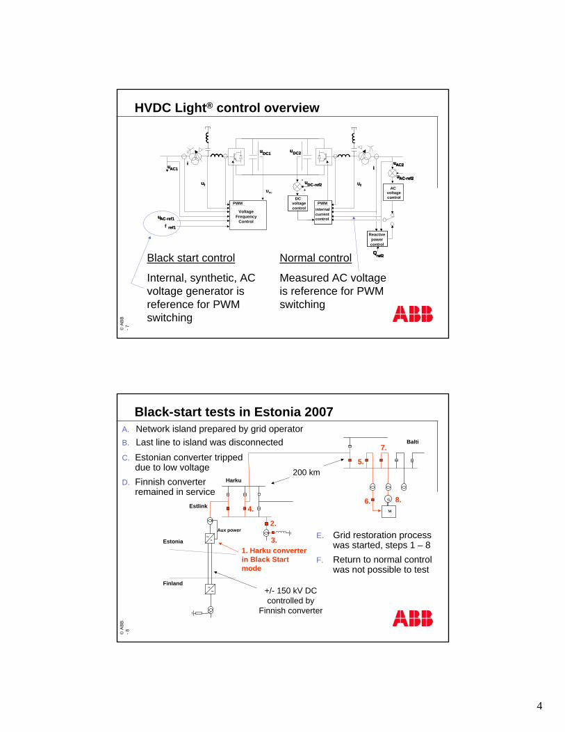
HVDC Light® control overview
uDC1
uAC1
uAC-ref1
DCvoltagecontrol
uDC-ref2
uDC2
+
-
uAC2
uAC-ref2
ACvoltagecontrol
PWMinternalcurrentcontrol
PWMinternalcurrentcontrol
ii
Qref2
Reactivepowercontrol
Uf Uf
uDC
uDC1
uAC1
uAC-ref1
DCvoltagecontrol
uDC-ref2
uDC2
+
-
uAC2uAC2
uAC-ref2uAC-ref2
ACvoltagecontrol
PWMinternalcurrentcontrol
PWM
ii
Qref2Qref2
Reactivepowercontrol
Reactivepowercontrol
Uf Uf
VoltageFrequency
Controlref1f ref1
Normal control
Measured AC voltageis reference for PWM switching
Black start control
Internal, synthetic, AC voltage generator is reference for PWM switching
©AB
B -8
Black-start tests in Estonia 2007A. Network island prepared by grid operatorB. Last line to island was disconnected
∼=
G
Harku
EstlinkM
1. Harku converterin Black Start mode
Balti
∼=
Estonia
Finland
Aux power
C. Estonian converter trippeddue to low voltage
D. Finnish converterremained in service
E. Grid restoration process was started, steps 1 – 8
F. Return to normal control was not possible to test
8.
2.
4.
7.
6.
5.
3.
200 km
+/- 150 kV DCcontrolled by
Finnish converter
5
©AB
B -9
∼=
G
Harku
EstlinkM
1.
Balti
∼=
Estonia
Finland
Aux power
8.
2.
4.
7.
6.
5.
3.
200 km
+/- 150 kV DCcontrolled by
Finnish converter
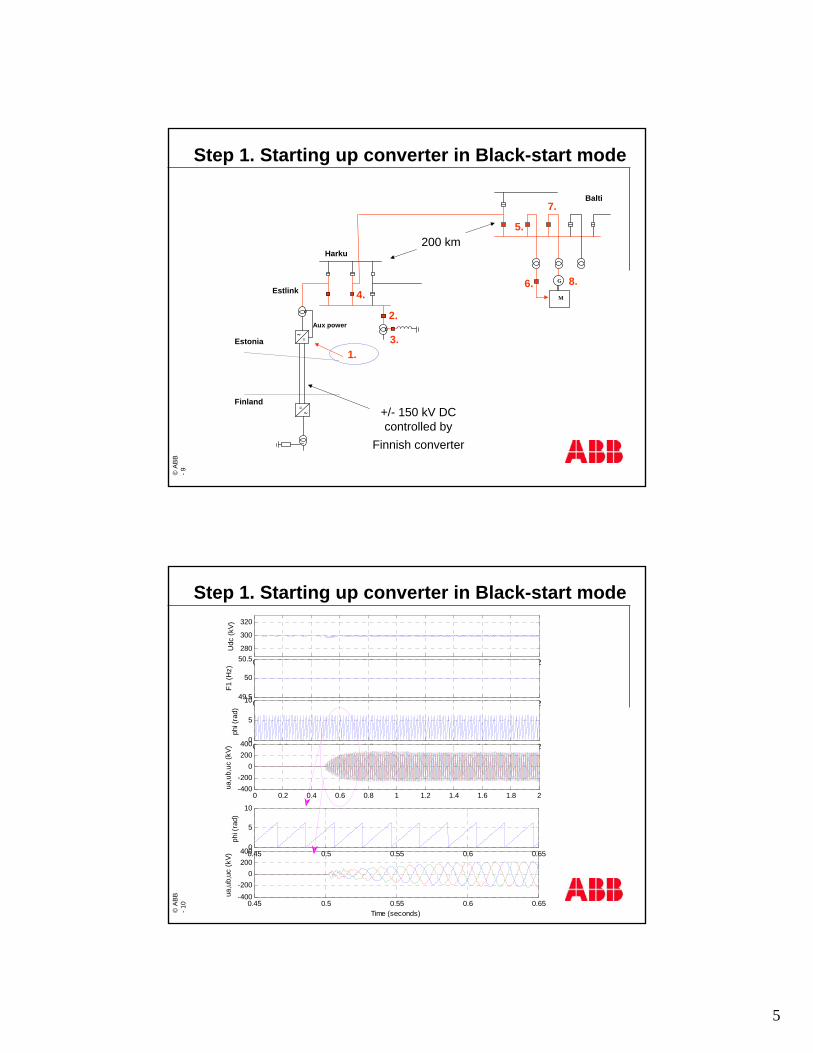
Step 1. Starting up converter in Black-start mode©
ABB
-10
Step 1. Starting up converter in Black-start mode
0 0.2 0.4 0.6 0.8 1 1.2 1.4 1.6 1.8 2
280
300
320
Udc
(kV)
0 0.2 0.4 0.6 0.8 1 1.2 1.4 1.6 1.8 249.5
50
50.5
F1 (H
z)
0 0.2 0.4 0.6 0.8 1 1.2 1.4 1.6 1.8 20
5
10
phi (
rad)
0 0.2 0.4 0.6 0.8 1 1.2 1.4 1.6 1.8 2-400-200
0200400
ua,u
b,uc
(kV)
0.45 0.5 0.55 0.6 0.65-400-200
0200400
Time (seconds)
ua,u
b,uc
(kV) 0.45 0.5 0.55 0.6 0.65
0
5
10
phi (
rad)

6
©AB
B -1
1
7.
∼=
G
Harku
EstlinkM
1.
Balti
∼=
Estonia
Finland
Aux power
8.
2.
4. 6.
5.
3.
200 km
+/- 150 kV DCcontrolled by
Finnish converter
Step 2. Energizing a 250 MVA transformer©
ABB
-12
0 0.5 1 1.5 2 2.5 3
280
300
320
0 0.5 1 1.5 2 2.5 3300
320
340
360
0 0.5 1 1.5 2 2.5 349.5
50
50.5
0 0.5 1 1.5 2 2.5 3-50
0
50
Time (seconds)
Udc (kV)
Uac-ref (kV)Uac (kV)
F1 (Hz)
P (MW)Q (MVar)
Step 2. Energizing a 250 MVA transformer

7
©AB
B -1
3
∼=
G
Harku
EstlinkM
1.
Balti
∼=
Estonia
Finland
Aux power
8.
2.
4.
7.
6.
5.
3.
200 km
+/- 150 kV DCcontrolled by
Finnish converter
Step 3. Switching in a 50 Mvar shunt reactor©
ABB
-14
Step 3. Switching in a 50 Mvar shunt reactor
0 0.5 1 1.5 2 2.5 3
280
300
320
0 0.5 1 1.5 2 2.5 3300
320
340
360
0 0.5 1 1.5 2 2.5 349.5
50
50.5
0 0.5 1 1.5 2 2.5 3-50
0
50
Time (seconds)
Udc (kV)
Uac-ref (kV)Uac (kV)
F1 (Hz)
P (MW)Q (MVar)

8
©AB
B -1
5
∼=
G
Harku
EstlinkM
1.
Balti
∼=
Estonia
Finland
Aux power
8.
2.
4.
7.
6.
5.
3.
200 km
+/- 150 kV DCcontrolled by
Finnish converter
Step 4. Switching in a 330 kV line (200 km long) ©
ABB
-16
Step 4. Switching in a 330 kV line (200 km long)
0 0.5 1 1.5 2 2.5 3
280
300
320
0 0.5 1 1.5 2 2.5 3300
320
340
360
0 0.5 1 1.5 2 2.5 349.5
50
50.5
0 0.5 1 1.5 2 2.5 3-100
-50
0
50
100
Time (seconds)
Udc (kV)
Uac-ref (kV)Uac (kV)
F1 (Hz)
P (MW)Q (MVar)

9
©AB
B -1
7
∼=
G
Harku
EstlinkM
1.
Balti
∼=
Estonia
Finland
Aux power
8.
2.
4.
7.
6.
5.
3.
200 km
+/- 150 kV DCcontrolled by
Finnish converter
Step 5. Energizing a distant 25 MVA transformer©
ABB
-18
Step 5. Energizing a distant 25 MVA transformer
0 0.5 1 1.5 2 2.5 3
280
300
320
0 0.5 1 1.5 2 2.5 3300
320
340
360
0 0.5 1 1.5 2 2.5 349.5
50
50.5
0 0.5 1 1.5 2 2.5 3-100
-50
0
50
100
Time (seconds)
Udc (kV)
Uac-ref (kV)Uac (kV)
F1 (Hz)
P (MW)Q (MVar)
10
©AB
B -1
9
∼=
G
Harku
EstlinkM
1.
Balti
∼=
Estonia
Finland
Aux power
8.
2.
4.
7.
6.
5.
3.
200 km
+/- 150 kV DCcontrolled by
Finnish converter
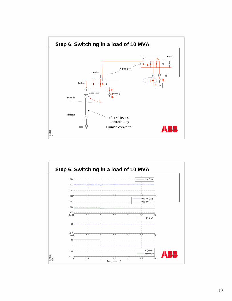
Step 6. Switching in a load of 10 MVA©
ABB
-20
Step 6. Switching in a load of 10 MVA
0 0.5 1 1.5 2 2.5 3
280
300
320
0 0.5 1 1.5 2 2.5 3300
320
340
360
0 0.5 1 1.5 2 2.5 349.5
50
50.5
0 0.5 1 1.5 2 2.5 3-100
-50
0
50
100
Time (seconds)
Udc (kV)
Uac-ref (kV)Uac (kV)
F1 (Hz)
P (MW)Q (MVar)

11
©AB
B -2
1
∼=
G
Harku
EstlinkM
1.
Balti
∼=
Estonia
Finland
Aux power
8.
2.
4.
7.
6.
5.
3.
200 km
+/- 150 kV DCcontrolled by
Finnish converter
Step 7. Synchronized switching in a 250 MVA generator©
ABB
-22
Step 7. Synchronized switching in a 250 MVA generator
1 1.5 2 2.5 3 3.5 4 4.5 5 5.5 6
280
300
320
1 1.5 2 2.5 3 3.5 4 4.5 5 5.5 6300
320
340
360
1 1.5 2 2.5 3 3.5 4 4.5 5 5.5 649.5
50
50.5
1 1.5 2 2.5 3 3.5 4 4.5 5 5.5 6-100
-50
0
50
100
Time (seconds)
Udc (kV)
Uac-ref (kV)Uac (kV)
F1 (Hz)
P (MW)Q (MVar)
12
©AB
B -2
3
∼=
G
Harku
EstlinkM
1.
Balti
∼=
Estonia
Finland
Aux power
8.
2.
4.
7.
6.
5.
3.
200 km
+/- 150 kV DCcontrolled by
Finnish converter
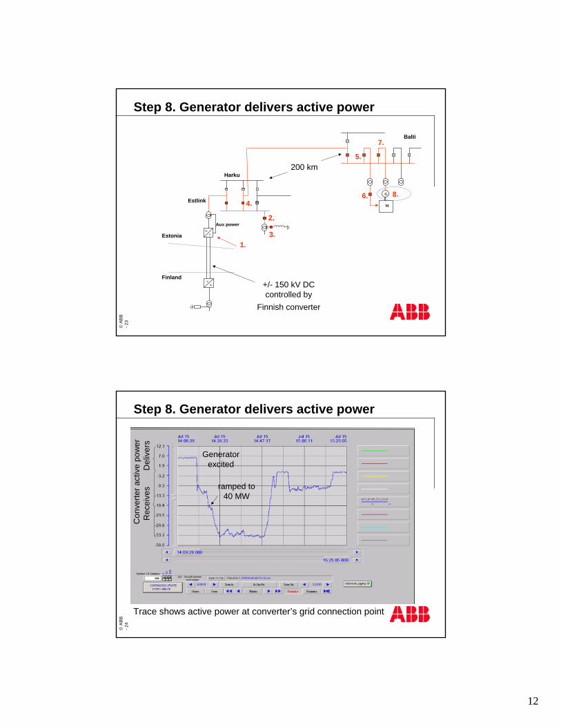
Step 8. Generator delivers active power©
ABB
-24
Step 8. Generator delivers active power
Con
verte
ract
ive
pow
erR
ecei
ves
Del
iver
s
Generator excited
ramped to 40 MW
Trace shows active power at converter’s grid connection point
13
©AB
B -2
5
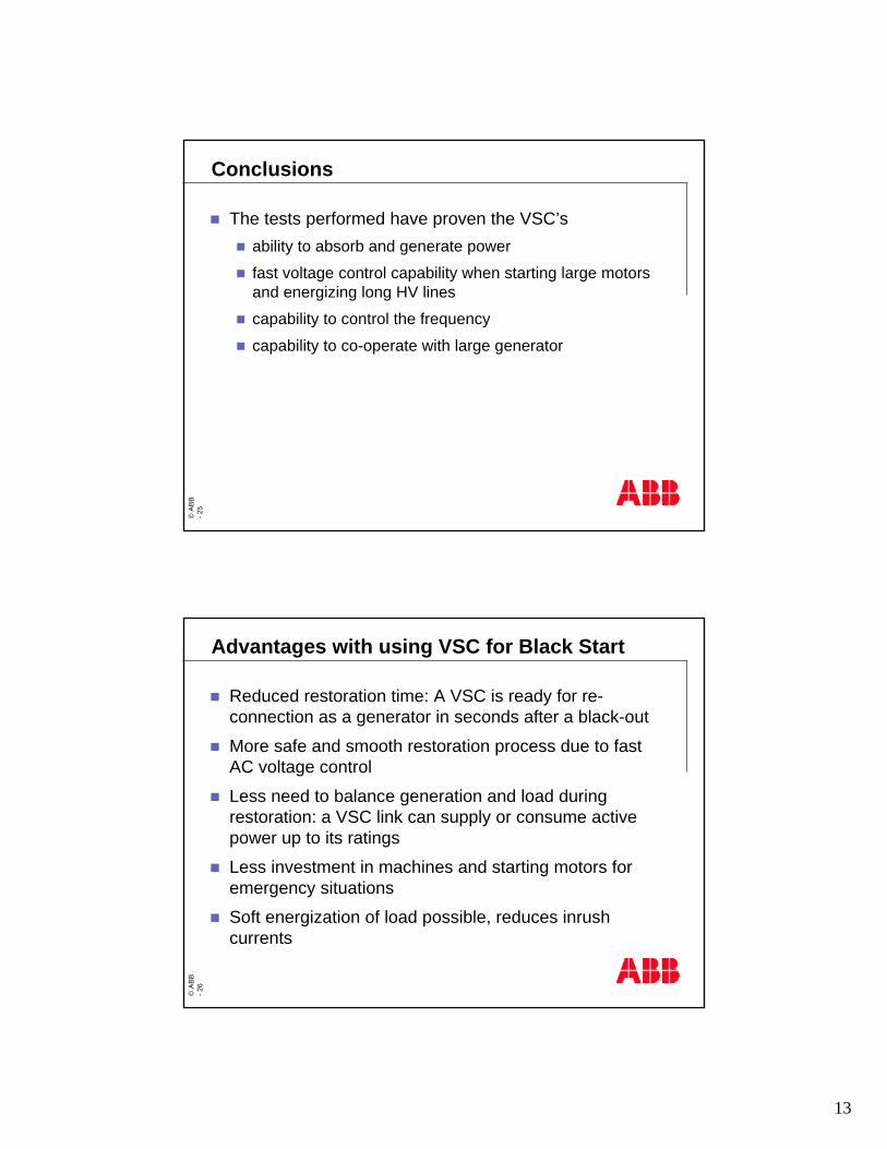
Conclusions
The tests performed have proven the VSC’sability to absorb and generate power
fast voltage control capability when starting large motors and energizing long HV lines
capability to control the frequency
capability to co-operate with large generator
©AB
B -2
6
Advantages with using VSC for Black Start
Reduced restoration time: A VSC is ready for re-connection as a generator in seconds after a black-out
More safe and smooth restoration process due to fast AC voltage control
Less need to balance generation and load during restoration: a VSC link can supply or consume active power up to its ratings
Less investment in machines and starting motors for emergency situations
Soft energization of load possible, reduces inrush currents

14