089 ' # '6& *#0 & 7 - InTechcdn.intechopen.com/pdfs-wm/33160.pdfLatest Generation Sinter Process...
22
3,350+ OPEN ACCESS BOOKS 108,000+ INTERNATIONAL AUTHORS AND EDITORS 115+ MILLION DOWNLOADS BOOKS DELIVERED TO 151 COUNTRIES AUTHORS AMONG TOP 1% MOST CITED SCIENTIST 12.2% AUTHORS AND EDITORS FROM TOP 500 UNIVERSITIES Selection of our books indexed in the Book Citation Index in Web of Science™ Core Collection (BKCI) Chapter from the book Sintering - Methods and Products Downloaded from: http://www.intechopen.com/books/sintering-methods-and- products PUBLISHED BY World's largest Science, Technology & Medicine Open Access book publisher Interested in publishing with IntechOpen? Contact us at [email protected]
Transcript of 089 ' # '6& *#0 & 7 - InTechcdn.intechopen.com/pdfs-wm/33160.pdfLatest Generation Sinter Process...

3,350+OPEN ACCESS BOOKS
108,000+INTERNATIONAL
AUTHORS AND EDITORS115+ MILLION
DOWNLOADS
BOOKSDELIVERED TO
151 COUNTRIES
AUTHORS AMONG
TOP 1%MOST CITED SCIENTIST
12.2%AUTHORS AND EDITORS
FROM TOP 500 UNIVERSITIES
Selection of our books indexed in theBook Citation Index in Web of Science™
Core Collection (BKCI)
Chapter from the book Sintering - Methods and ProductsDownloaded from: http://www.intechopen.com/books/s intering-methods-and-products
PUBLISHED BY
World's largest Science,Technology & Medicine
Open Access book publisher
Interested in publishing with IntechOpen?Contact us at [email protected]
1
Latest Generation Sinter Process Optimization Systems
Thomas Kronberger, Martin Schaler and Christoph Schönegger Siemens VAI Metals Technologies GmbH (Siemens VAI) Linz,
Austria
1. Introduction
SIMETAL Sinter VAiron is an advanced process optimization system which covers the sinter production process from ore preparation in the blending yards and sinter plant up to the blast furnace. It was developed in a close cooperation between the Austrian steel producer voestalpine Stahl and the engineering and plant-building company Siemens VAI. The overall target of this system is to achieve stable process conditions at a high productivity level with a uniform sinter quality at low production costs. This is achieved through the application of a number of sophisticated tracking, diagnosis and control models and systems which are bundled within an overall expert system.
2. System objectives
In the sintering process, chemical and physical parameters such as basicity and product diameters must satisfy pre-set target values within defined standard deviations in order to meet the quality requirements of the blast furnace. Sinter quality begins with the selection and mixing of the raw materials in the blending yard and dosing plant which are integrated in a common control model of the Sinter Process. The chemical properties are homogenized by an automatic adaptation of the raw material mix. An enhanced burn-through-point control system which takes into account physical and chemical properties of the sinter mix is incorporated in the system. The system has to counteract changes caused by fluctuations, which is achieved by a closed-loop control of the process.
The main targets of the SIMETAL Sinter VAiron1 process control system are summarized as follows:
• Minimizing fuel consumption – The fuel rate is a key factor in production costs.
• Avoidance of heavy control actions – If only minor control actions are necessary, the sinter machine performance is stabilized significantly.
• Avoidance of critical process situations – The sooner the system reacts to critical process situations, such as an inhomogeneous mixture, poor surface ignition or incomplete burn-through of mix, the smoother the overall sintering process is, resulting in a more uniform product quality.
1Later on in this document we will briefly call the system ‘VAiron Sinter’.
www.intechopen.com

Sintering – Methods and Products
4
• Synoptical operational decisions throughout all shifts – Constant operating conditions throughout all shifts will increase the lifetime of the equipment and reduce production costs.
• Reduction of emissions – With the closed-loop operation mode of the VAiron Sinter Expert System, the production parameters can be optimized within the environmental emission limits, in particular, SO2 emissions.
3. System structure and technological controls
A reliable and well proven basis automation system is the backbone of modern sinter plant
operation. VAiron Sinter is characterized by a modular system structure (Fig. 1).
Fig. 1. System Structure.
In addition to basic functions such as data acquisition and set-point execution, the technological controls (main control loops) are implemented in the basis automation system. These include raw-mix-ratio control, raw-mix-feed control, moisture control, surge-hopper-level control, drum-feeder control, ignition-hood control, exhaust-gas-cooler control and cooler control. The focus of these basic control functions is to assure a smooth and reliable sintering process and to enable a continued process optimization.
3.1 VAironment – Process information and data-management system
A multithreaded, three-tier, client-server real-time application is the basis for the hardware and software configuration in VAiron Sinter. The data acquisition function pre-processes the data from a broad spectrum of raw data sources (front-end signals, material weights, laboratory data, events, model results and cost data, etc.) before storing these in the plant database (Fig. 2).
www.intechopen.com
Latest Generation Sinter Process Optimization Systems
5
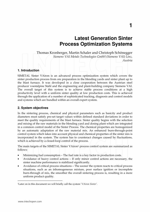
Fig. 2. VAironment Process Information and Data Management System.
The process information management system provides a flexible and powerful database for the continuous improvement of process knowledge. VAiron Sinter interprets process data, performs model calculations and visualizes the results in Windows- or web-based graphical user interfaces. Additional data analysis, interpretation and visualization tools can connect to VAiron easily (COM, ODBC). The module-based system is highly configurable in order to allow for adaptations related to modifications in the plant setup or operational philosophy.
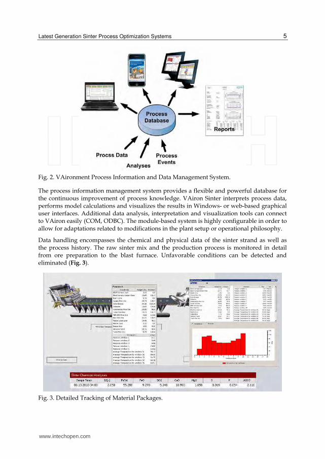
Data handling encompasses the chemical and physical data of the sinter strand as well as the process history. The raw sinter mix and the production process is monitored in detail from ore preparation to the blast furnace. Unfavorable conditions can be detected and eliminated (Fig. 3).
Fig. 3. Detailed Tracking of Material Packages.
www.intechopen.com

Sintering – Methods and Products
6
3.2 VAiron process models
A number of process models are available in the VAiron Sinter automation package as outlined in the following.
3.2.1 Raw mix calculation model
Producing target quality requires accurate charging of the raw materials (ores, coke, additives, etc.). To modify the raw mix recipe, the coke addition, sinter basicity, raw material analyses and their influence on sinter parameters must be taken into consideration. This procedure is complex and requires computer assistance.
The purpose of the raw mix calculation model is to establish a raw mix composition, in
order to automatically achieve the assigned target values for coke addition, sinter basicity,
Fetot, SiO2, etc.
Up to four variable materials may be chosen – one for the basicity equation, one for Fetot
balance, and one for SiO2 balance as well as one for the MgO balance.
The results of the raw mix calculation can be activated manually to run on Level 1.
Fig. 4. Raw Mix Calculation for Sinter Plant.
In combination with the Expert System, the raw mix calculation model is a central part of the closed-loop operation, which is a unique highlight of the VAiron Sinter automation solution. A screen of the user interface of the raw mix calculation model is shown in Fig. 4.
www.intechopen.com

Latest Generation Sinter Process Optimization Systems
7
3.2.1.1 Calculation of material ratios (backward calculation)
The aim of this calculation mode is to calculate the set-points for the raw material system
(material ratios) in order to reach the chemical sinter composition with the desired results.
Fig. 5. Backward Calculation Procedure.
Several calculation options are available:
• To aim at a certain basicity
• To aim at a certain Fetot
• To aim at a certain SiO2
• To aim at a certain MgO
• Calculation of the set-point for fuel materials
The advantage of the backward calculation (Fig. 5) is to reach and keep the product quality
as stable as possible and optimize the material costs.
3.2.1.2 Calculation of sinter composition (forward calculation)
The target of this calculation is the opposite of the calculation of the raw material ratios, i.e. to
calculate the chemical analysis of sinter using the composition of the raw materials as an input.
Using this calculation option, the model calculates the theoretic chemical composition of the
sinter product based on fixed material ratios input by process engineers or operators.
Fig. 6. Forward Calculation Procedure.
3.2.1.3 Online calculation of sinter composition (forward calculation)
This calculation is identical to the previously described calculation of the sinter composition
with the difference that the actual charged material ratios from Level 1 are used as input for
the calculation. Therefore, the model is started automatically in the background when a new
Level 1 recipe is detected and it calculates the actual sinter composition using the actual raw
mix data.
3.2.2 Stacking plan for blending ore bed
The model calculates a stacking plan for blending ore beds based on the raw mix
composition calculated by the corresponding raw mix calculation. After considering the
www.intechopen.com
Sintering – Methods and Products
8
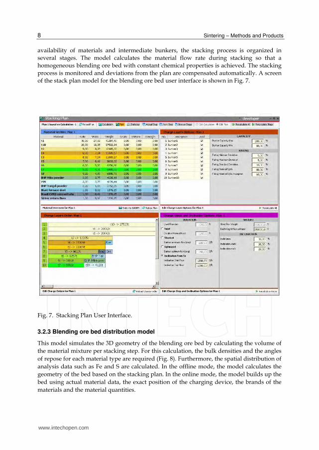
availability of materials and intermediate bunkers, the stacking process is organized in
several stages. The model calculates the material flow rate during stacking so that a
homogeneous blending ore bed with constant chemical properties is achieved. The stacking
process is monitored and deviations from the plan are compensated automatically. A screen
of the stack plan model for the blending ore bed user interface is shown in Fig. 7.
Fig. 7. Stacking Plan User Interface.
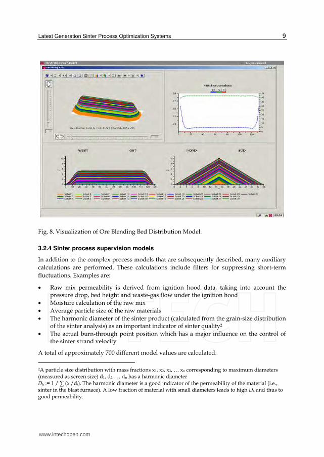
3.2.3 Blending ore bed distribution model
This model simulates the 3D geometry of the blending ore bed by calculating the volume of
the material mixture per stacking step. For this calculation, the bulk densities and the angles
of repose for each material type are required (Fig. 8). Furthermore, the spatial distribution of
analysis data such as Fe and S are calculated. In the offline mode, the model calculates the
geometry of the bed based on the stacking plan. In the online mode, the model builds up the
bed using actual material data, the exact position of the charging device, the brands of the
materials and the material quantities.
www.intechopen.com
Latest Generation Sinter Process Optimization Systems
9
Fig. 8. Visualization of Ore Blending Bed Distribution Model.
3.2.4 Sinter process supervision models
In addition to the complex process models that are subsequently described, many auxiliary
calculations are performed. These calculations include filters for suppressing short-term
fluctuations. Examples are:
• Raw mix permeability is derived from ignition hood data, taking into account the pressure drop, bed height and waste-gas flow under the ignition hood
• Moisture calculation of the raw mix
• Average particle size of the raw materials
• The harmonic diameter of the sinter product (calculated from the grain-size distribution of the sinter analysis) as an important indicator of sinter quality2
• The actual burn-through point position which has a major influence on the control of the sinter strand velocity
A total of approximately 700 different model values are calculated.
2A particle size distribution with mass fractions x1, x2, x3, … xn corresponding to maximum diameters (measured as screen size) d1, d2, … dn has a harmonic diameter Dh := 1 / ∑ (xi/di). The harmonic diameter is a good indicator of the permeability of the material (i.e., sinter in the blast furnace). A low fraction of material with small diameters leads to high Dh and thus to good permeability.
www.intechopen.com

Sintering – Methods and Products
10
3.2.5 Burn-through time prediction model
The model predicts the dynamic behaviour of the sintering based on the process conditions
and raw mix parameters, including permeability and waste-gas data. The predicted burn-
through time is used as an important input parameter for the advanced control strategy of
the Sinter VAiron burn-through point controller.
3.2.6 Productivity analysis tool
VAironment allows for the long-term archiving of recipes, chemical and physical analyses
and all kinds of measured process data. This comprehensive data archive allows for the
retrospective analysis of best process conditions for specific raw materials. The productivity
analysis tool supports highly sophisticated search strategies in finding optimal process
parameters for a given raw material according to different objectives, such as a maximal
productivity and minimal fuel consumption.
3.2.7 Sinter process model
The top layer of the raw mix is ignited in the ignition hood. After the sinter mix leaves the
ignition hood, combustion continues by drawing air through the bed which progresses
downwards through the entire bed. When the combustion reaches the bottom layer of the
sinter mix, the entire bed has been sintered. This point is called the sintering point or burn-
through point (BTP).
Proper control of the sinter strand speed aims at positioning the BTP close to the end of the
strand. If the BTP is situated before that ideal position, the area after the BTP is only used for
cooling the sinter. This leads to a diminution of the active sintering area and a productivity
decrease. If it is not reached within the sinter strand, un-sintered sinter mix is discharged
and has to be recycled as return fines – leading to a productivity decrease. Furthermore, this
results in poor sinter quality. The position of the BTP is measured by thermocouples
installed in the last suction boxes and is characterized by the maximum value of the exhaust
gas temperature detected by the thermocouples within these suction boxes.
A paramount control goal in the sintering process is that the material must be completely
sintered by the time it reaches the end of the sinter strand (minimized return fines) and that
the BTP is as close as possible to the ideal position for maximum productivity.
The gas flow through the sinter strand is a function of the permeability of the raw mix. As
the total sintering time depends on the total gas flow, a higher permeability will obviously
lead to shorter burn-through times. However, it is also clear that a higher gas flow through
one section of the sinter strand will slightly reduce the gas flow through the material in
other zones along the sinter strand. Taking this into consideration, a permeability-based
simulation of the sintering process can thus be applied for an improved sinter-process
control to achieve higher productivity. This solution approach was implemented in the
sinter plant control system.
For example, the pronounced rise in the BTP curve beginning at time interval 43 of Fig. 9 is a consequence of an increased permeability of the raw mix at this position. The temporary BTP drop immediately preceding this rise is a result of the reduced gas flow through the
www.intechopen.com

Latest Generation Sinter Process Optimization Systems
11
raw mix, as explained above. As soon as the permeability falls, the BTP curve also drops accordingly (time interval 54). The inexact response correlation between the flat trend of the permeability curve and the irregular trend of the BTP can be explained as being the result of the accumulated nonlinear effects of varying gas flows through different sections of the sinter strand on the BTP. On the right-hand side of the diagram (time intervals 80 to 113), the inverse situation for a reduced permeability is shown.
Fig. 9. Illustration of Simulated Dependency Between Permeability of Raw Mix and Distance
of BTP from End of Sinter Strand; Plotted as Function Of Time (measured in arbitrary units).
If the sinter is not completely burned through before reaching the end of the strand, a decrease of the sinter strand speed is the logical control action. Choosing the proper speed reduction for the sinter at the end of the strand will result in an increased duration of the material spent at the beginning of the strand that is longer than ideal. This sinter will be burned through before reaching the end of the sinter strand, again necessitating an increase in the strand speed. This, in turn, means that the BTP of the following material will again be too close to the end of the sinter strand. For conventional automation solutions, e.g., PID (Proportional Integral Differential)-based control, this effect tends to lead to BTP and thus strand-speed oscillations when trying to compensate for the fluctuations. The sintering process model predicts the Burn-Through Time (BTT) as an indicator for the dynamic behavior of sintering, based on the process conditions and raw mix parameters, e.g., the material permeability. The compiled prediction of the BTT for discrete sinter strand segments is one of the important starting points for the calculation of the optimum sinter-strand speed by the Expert System.
3.3 VAiron sinter expert system
One of the most important factors for the control of the sinter process is to make operation
of the sinter plant as smooth and steady as possible. The process can be disturbed, however,
www.intechopen.com
Sintering – Methods and Products
12
by changes in the properties of charged materials, failures in the process, human factors,
process conditions, etc. Delays in corrective measures compensating for the interference
factors may vary from minutes to hours, days and weeks. Correct timing of control actions
and anticipation of disturbances is of utmost importance for maintaining high production
rates and low production costs.
The knowledge of experienced sinter process engineers and operators on the process, the cause and effect relationships of process disturbances, metallurgical know-how, and the adopted control philosophy is modeled into the expert system. It monitors and forecasts the process status, gives alarms in case of process disturbances, suggests control measures, and describes the changes in the process in the form of verbal messages and graphical displays. With the help of the experts system, the expertise of the process control personnel is improved, the process control practice among the different shifts becomes more uniform, and, on the basis of forecasting, the operation of the process becomes smoother as compared to conventional process control. Monitoring of measurement data and indices based on those measurements becomes more efficient with the help of the expert system.
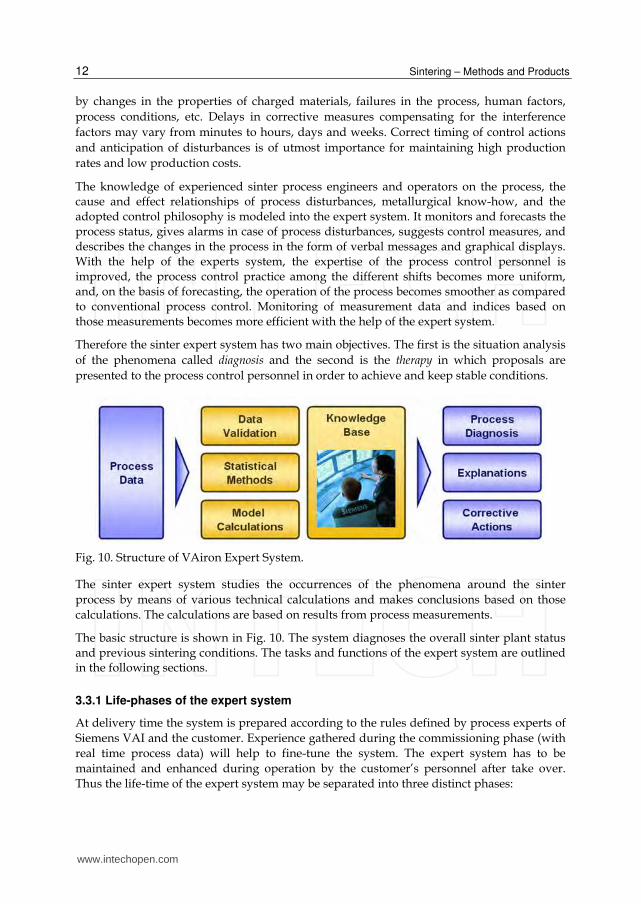
Therefore the sinter expert system has two main objectives. The first is the situation analysis
of the phenomena called diagnosis and the second is the therapy in which proposals are
presented to the process control personnel in order to achieve and keep stable conditions.
Fig. 10. Structure of VAiron Expert System.
The sinter expert system studies the occurrences of the phenomena around the sinter
process by means of various technical calculations and makes conclusions based on those
calculations. The calculations are based on results from process measurements.
The basic structure is shown in Fig. 10. The system diagnoses the overall sinter plant status and previous sintering conditions. The tasks and functions of the expert system are outlined in the following sections.
3.3.1 Life-phases of the expert system
At delivery time the system is prepared according to the rules defined by process experts of
Siemens VAI and the customer. Experience gathered during the commissioning phase (with
real time process data) will help to fine-tune the system. The expert system has to be
maintained and enhanced during operation by the customer’s personnel after take over.
Thus the life-time of the expert system may be separated into three distinct phases:
www.intechopen.com

Latest Generation Sinter Process Optimization Systems
13
Phase Responsible Description
Development of base system (based on Siemens VAI’s experience and customer’s know-how)
SVAI Implementation of diagnosis structure, implementation of described diagnoses and actions, implementation of explanation capability, implementation of interfaces
Fine-tuning during commissioning (based on operational data)
SVAI / Customer
Fine-tuning of described diagnoses and actions
Maintenance and further enhancements (based on operational data)
Customer Further adaptations, reaction on equipment changes, implementation of new diagnoses and/or actions
Table 1. Life-phases of the expert system.
Modifications of the expert system can be done by the customer’s personnel according to the
following topics:
• Fine-tuning of delivered diagnoses and rules - As described above the expert system
has to be maintained throughout its lifetime. The simplest form of maintenance is fine
tuning of the delivered application, i.e. modifications of existing but no addition of new
parts. Customer’s personnel may change tuning parameters stored outside the expert
system.
• Addition of other diagnoses - If the expert system shall increase its diagnosing
capability, one has to add new diagnoses.
• Addition of other therapies - If new suggestions of corrective actions shall be provided
by the expert system, one has to add new rules.
The VAiron Sinter expert system includes a Metallurgical Model Toolbox and its own
scripting language. This toolbox enables the modification of the logics of existing diagnosis
and rules and the creation of new diagnosis and rules based on the specific requirements of
operation.
3.3.2 Sinter plant control HMI – Expert system
Various process model results, control trends as well as the diagnoses are visualized in this
HMI. It offers the following functionality:
• Checking of the performance of the various models using dedicated screens, i.e. tab
folders in the Sinter Plant Control HMI.
• Modification of parameters for the individual models.
• Switching between closed-loop and semi-automatic mode for the individual controls.
The expert system HMI looks as follows:
www.intechopen.com

Sintering – Methods and Products
14
Fig. 11. Sinter Expert System HMI.
3.3.3 Diagnoses
The expert system studies the occurrence of phenomena in the sinter process using a variety of technical calculations and it draws conclusions derived from them. The calculations are based on a large amount of process measurement and analyses data that is collected continuously.
The following standard diagnoses are provided by the expert system:
Diagnosis Description
Production A moving average of the sinter production over a certain period of time (e.g. 1 hour) compared to the target sinter production.
Fuel Consumption Moving average of the fuel consumption over a dedicated period of time (e.g. 1 hour) compared to target fuel consumption.
Chemical Quality The basicity of the last received chemical sinter analysis is compared to the target basicity value.
Physical Quality The harmonic diameter of the last received physical analysis is compared to the target value.
Environment A moving average of the components of the waste gas analysis over a certain period of time (e.g. 1 hour) is compared to their target values.
Waste Gas Temperature Moving average of temperature measurements in the main duct before the E.P. over a certain time period (e.g. 1/2 hours) is compared to the target value.
Table 2. Provided Expert System diagnoses.
www.intechopen.com
Latest Generation Sinter Process Optimization Systems
15
3.3.4 Therapy
The expert system provides the following two types of user notifications regarding the
therapy to achieve and keep a stable and smooth sinter process:
• Plausibility checks on measurements • Corrective actions
3.3.4.1 Plausibility checks on measurements
A check action is created and presented to the user for all process variables that were found
to be initially missing or invalid.
No further checks on the equipment are provided. This means that there are no further examinations, whether the measuring device is really faulty or not.
The check actions are given in textual form like
• The temperature of thermocouple in wind box #13 is unusual and therefore suspicious • The analysis deviation (100%-∑elements) of the Sinter analysis exceeds 10%. Please
check the analysis.
3.3.4.2 Corrective actions
Corrective actions are proposals for the operating personnel to change some process
parameters (set-points). The expert system suggests at the same time one or more corrective
actions out of a set of possible ones. Some of the corrective actions are provided
qualitatively, that means the expert system suggests increasing or decreasing something
instead of giving exact values to the user. Others are provided quantitatively, that means the
new set-point is provided by the expert system.
Internally, the process of suggesting a corrective action is functionally divided into three
groups based on the respective objectives as shown below:
• Situation Analysis (to judge the kind of process variations that have occurred) • Phenomenon Recognition (to judge the kind of phenomenon expressed by that
variation)
• Action Determination (to judge the action against the phenomenon)
Selected corrective actions have to be acknowledged by the operators. This is especially
necessary if the expert system is in semi-automatic mode. The operators can enter a reason if
they do not follow the expert system's suggestions and this action is suppressed until its
status changes. This gives important information for tuning of the expert system.
The action execution can be separated into two operation modes which can be set for each
rule and control individually as follows:
• Semi-Automatic Mode • Closed-Loop Mode
The current operation mode for each rule/control is displayed in the expert system HMI
(section) and indicated by green and red lights (see Fig. 11). The distinction between semi-
automatic and closed-loop mode is described in detail in the section below.
www.intechopen.com

Sintering – Methods and Products
16
Semi-automatic mode
If a rule or control is in semi-automatic mode, a detailed description of all recommended
changes is provided to the operator by the expert system. During a configurable period of
time (usually 10 – 15 minutes) the operator has the possibility to accept or decline the
suggestion.
In case of rejecting the suggestion no further action will be executed. Additionally an input
field is provided to key in a reason for refusing this suggestion.
If the operator has the opinion that the suggested set-point/recipe change is necessary to
keep smooth process conditions, he has the possibility to accept the change. Afterwards the
expert system is executing the changes and sends the new set-points/raw mix recipe to the
Level 1 system automatically.
In case of neither rejecting nor accepting the recommended set-point/recipe change during the configurable period of time, the expert system will automatically reject the recommendation and no further actions will be executed as well.
Closed loop mode
For the recommendations of rules and controls switched to Level 2 closed loop mode a detailed description of necessary changes is provided as well. The pending time, in which the operator can accept or decline this suggestion, is also configurable (usually 5 – 10 minutes).
The only significant difference to the semi-automatic mode is the behavior after expiration of the configurable period of time without an operator action. In the closed loop case, contrary to the semi-automatic mode, the expert system will automatically accept the recommended changes and sends the new set-points/recipe to the Level 1 system.
3.3.4.3 Controls
Controls are actions that are executed continuously (e.g. every minute) for fast reactions to keep the process stable and usually run silently in the background. They are typically switched on or off on Level 1. Controls may also use a validity flag indicating its state to Level 1.
The controls shown in the following table are typically included in the expert system.
Corrective Action Description
Change position of feeder gates
To ensure a homogeneous flame front in the transverse direction of the sinter strand, the transversal burn-through deviation control adjusts the packing degree. This leads to a constant burn-through of the sinter in transverse direction. The advantages for the sinter process are fewer and more stable sinter return fines.
Change sinter machine strand speed
The burn-through-point control maintains a target of the burn-through-position. This is achieved by modifying the speed of the sinter strand in accordance with the preset burn-through point position. The effect of this control leads to a maximized possible production of the used raw mix composition.
Table 3. Expert System Controls.
www.intechopen.com
Latest Generation Sinter Process Optimization Systems
17
3.3.4.4 Rules
Rules are actions that are suggested at specific events (e.g. new sinter analysis) or they are triggered periodically. Since rules are slower controls or major changes in plant operation, a rule is always explained textually. So an operator can decide if he wants to follow the rule or not. In case of switching a rule to closed loop mode, it will be processed automatically after a certain period of time if the operator does not reject the suggestion with the expert system user interface.
The rules shown in the following table are evaluated by the expert system.
Corrective Action
Description
Change Basicity
Sinter properties represented by chemical parameters such as the basicity (CaO/SiO2) have to be kept within an acceptable deviation from the preset target values. This control loop adjusts the raw mix composition in order to maintain the target values.
Re-Calculate current Recipe
In case of a new chemical analysis received from the laboratory for a material which is currently used in the active recipe, a new sinter calculation is performed.
Change sinter return fines
A harmonized sinter plant return fine bin level over a long term is the objective of the return fine control. The return fine consumption in the raw mix composition is adjusted to keep the return fine bin level within a range.
Change Coke for raw mix
In order to keep the FeO content of the sinter within an acceptable range, the coke control stabilizes the sinter return fine balance. Therefore, the control modifies the coke consumption in the raw mix composition in accordance with the sinter return fine balance.
Table 4. Expert System Rules.
3.3.5 Sinter plant productivity control
A very important part of the expert system represent the two controls described in section 3.3.4.3, namely the Burn-Through-Point and the Transversal Burn-Through-Point Controller. These controls improve the overall plant productivity.
There are many indicators for the strand-speed control with different precision. Some of these are available at an early stage in the process (e.g. the permeability), others only with long time delays after the process on the strand has been finished (e.g. the harmonic diameter). Generally, the information attained at a later stage is more precise than that attained early on.
The fundamental idea was therefore to use the early information to control the processes and to use the information that is attained at a later stage to self-tune the control system. With these two independent sources of information it is possible to achieve high control accuracy despite fast corrective actions. A general overview of the main parameters that affect productivity control is shown in Fig. 12. Since the availability and reliability of the listed data differs from plant to plant, the expert system can be based on individually selected entry data of the respective plant.
www.intechopen.com

Sintering – Methods and Products
18
Fig. 12. Overview of Sinter Plant Productivity Control.
In the longitudinal BTP optimization described above, the objective is to obtain an average
BTP position that is optimally distanced from the strand end. Full utilization of the surface
of the sinter strand, however, can only be achieved when, at the same time, the flame front
also reaches the lowest layer across the entire width of the strand (in a transversal direction).
This is obtained through the transverse burn-through point control (Fig. 13). Here, feedback
on the burn-through point is derived from the temperature conditions in a transverse
direction from the last suction boxes and corrective measures are then executed online
directly through proper adjustment of the angle of flaps near the drum feeder. In this
manner, a uniform flame front can be achieved.
Fig. 13. Transverse Burn-Through Point Control
www.intechopen.com
Latest Generation Sinter Process Optimization Systems
19
4. Savings and benefits
4.1 Advanced data management
From a broad spectrum of raw data sources, the data acquisition function pre-processes the
plant data before storing it in the plant database. This database is of key importance to the
advanced process optimization. The following data are collected from the process and
connected systems:
• Continuously measured process data from the Level 1 system
• Amount of material charged
• Plant status data (runtime, shut-down, special process situations, etc.)
• Chemical and/or physical laboratory analyses data of all raw-materials and sinter
• Active raw mix recipes
Additionally, applications to visualize the above mentioned collected data are provided:
• Tag-Visualization program for graphical representation of any kind of time-based data
in the database
• Lab-Browser application for material analyses visualization and evaluation
• Reporting system allowing for cyclical (e.g. daily) or on-demand report generation
The system can serve as a link between different automation levels in the customer’s
company: it is connected to the aggregate’s Level 1 automation and it can be connected to
the plant wide network. Therefore it can send production and consumption data as well as
important process data to a Level 3 system.
4.2 Increase of operator know how
The expert system generates textual explanations for its diagnoses and suggestions. In
combination with the graphical information provided by the system (see Section 3.3.2),
the operator can understand the actual situation of the plant in detail. Using these
facilities, the operator can permanently learn about the process and background of the
knowledge system. In consequence, the system will improve the skills of the operational
personnel.
4.3 Smooth plant operation
The expert system checks a number of process state indicators in a typical time cycle of five
minutes:
• Several hundred measurement points from the Level-1 automation, and
• Related model calculations for internal process states which cannot be measured
directly
Deviations from optimal process conditions can therefore be detected early. Small counter
actions are sufficient to correct the process conditions at this early stage. Even experienced
human operators are unable to cope with this flood of information and will detect such
deviations later than the expert system.
www.intechopen.com
Sintering – Methods and Products
20
In consequence, the main difference between manual operation and operation supported by the expert system is that the latter is characterized by more frequent, but smaller control actions. The resulting smooth operation of the sinter plant leads to:
• Higher availability of the sinter plant
• Longer overall lifetime of the sinter plant
• Reduced maintenance efforts and costs
4.4 Uniform operational philosophy
The VAiron expert system is customized for each individual plant where it is installed. In a
first phase, the customer specific situation regarding raw materials, plant topology,
equipment, etc. is analyzed. The specific rules are developed in cooperation between
Siemens VAI specialists and experienced process engineers and operators of the customer.
Specific customer operational philosophy is implemented instead of standard rules as a
result of this cooperation during the engineering phase. During system commissioning the
rules are fine-tuned together with the customer.
This approach has the following advantages:
• High acceptance of the system, because it reflects the internal operational philosophy
• The customer’s operational philosophy of the most experienced personnel is followed 24 hours a day, 7 days a week
• Consistent sinter plant operation over all shifts, resulting again in smoother plant operation
4.5 Increased sinter plant productivity
The use of the Burn-Through-Point controller typically leads to an increase in the sinter
plant productivity between 2% and 5%. An additional increase can be achieved if the flame
front is uniformed along the full width of the sinter strand by means of the Transversal
Burn-Through-Point Controller.
The usage of a higher percentage of sinter with stable quality in the blast furnace burden
results in a further reduction of the blast furnace fuel consumption. Therefore, the increase
of productivity of the sinter plant is a very important benefit of the expert system.
4.6 Reduced fuel consumption and stabilized sinter quality
The expert system ensures an economic fuel usage by keeping the return fines ratio at the
optimal level. Whenever the average production of internal return fines deviates from the
optimal value, the expert system corrects the process conditions (mainly the fuel addition) in
order to compensate the deviation. Reduced fuel consumption and increased productivity
are achieved by this control loop.
Stabilization of sinter quality is achieved by dedicated quality controllers considering
incoming sinter analyses from laboratory and performing corrections of the raw mix
recipe, if deviations in one of the following quality parameters from the target value are
detected:
www.intechopen.com
Latest Generation Sinter Process Optimization Systems
21
• Harmonic diameter of sinter
• Sinter basicity
• Sinter SiO2 content
• Sinter MgO content
• Sinter total Fe content
Additionally, fluctuations in raw material analyses are detected and the new optimum raw
mix composition is calculated immediately, downloaded to the Level 1 automation system,
and executed there. Obviously this proactive compensation of raw material fluctuations is
much faster than waiting to see effects in the produced sinter.
5. Summary and outlook
The sinter automation and optimization described in this chapter offers an integrated
approach for ore preparation and sintering operations in one system, assuring optimal
coordination of both plants. The application of the proven closed-loop expert system leads
to transparent and reliable process control and shift-independent sinter quality at a high
productivity level. The development of this system was an important step in the fulfillment
of the vision of "fully automatic sinter plant operation".
Before the described VAiron Sinter automation system has been developed, an analogous
automation package for blast furnaces was introduced by Siemens VAI in cooperation with
voestalpine Stahl. These systems have in common that they optimize a single aggregate. If
an iron making plant contains several blast furnaces and sinter plants, each system would
optimize a single aggregate.
Optimal conditions for a group of aggregates differ in general from optimum conditions at
each of the single aggregates. In consequence, the next step of development is the VAiron
Productivity Control System, which consists of a superordinated expert system considering
the whole iron making plant rather then single aggregates. The system considers the
• Coke oven plants
• Sinter plants
• Sinter stock yard
• Blast furnaces
of the iron making plant and coordinates all these aggregates. The system executes its
suggestions by sending set-points to the individual Level 2 systems of the single aggregates.
Up to now, a prototype of the VAiron Productivity Control System is installed at
voestalpine Stahl with promising results.
6. References
Klinger, A.; Kronberger, T., Schaler, M., Schürz, B. & Stohl, K. (2010). Expert Systems: Chapt. 7 Expert Systems Controlling the Iron Making Process in Closed Loop Operation, InTech, ISBN 978-953-307-032-2, Vukovar, Croatia
Bettinger, D., Schürz, B., Stohl, K., Widi, M., Ehler, W. & Zwittag, E. (2008). Get More From Your Ore, metals & mining, 1/2008
www.intechopen.com

Sintering – Methods and Products
22
Bettinger, D., Stohl, K., Schaler, M. & Matschullat, T. (2006). Automation Systems for Sustainable Energy Management, Proceedings of the Iron & Steelmaking Conference, Oct 9-10, 2006, Design Center Linz, Austria
Fan, X.H., Long, H.M., Wang, Y., Chen, X.L. & Jiang, T. (2006). Application of expert system for controlling sinter chemical composition, Ironmaking and Steelmaking, 3/2006
Sun Wendong, Bettinger, D., Straka, G. & Stohl, K. (2002). Sinter Plant Automation on a New Level!, Proceedings of AISE Annual Convention, Nashville, USA, Sep 30 – Oct 2, 2002
www.intechopen.com

Sintering - Methods and ProductsEdited by Dr. Volodymyr Shatokha
ISBN 978-953-51-0371-4Hard cover, 316 pagesPublisher InTechPublished online 23, March, 2012Published in print edition March, 2012
InTech EuropeUniversity Campus STeP Ri Slavka Krautzeka 83/A 51000 Rijeka, Croatia Phone: +385 (51) 770 447 Fax: +385 (51) 686 166www.intechopen.com
InTech ChinaUnit 405, Office Block, Hotel Equatorial Shanghai No.65, Yan An Road (West), Shanghai, 200040, China
Phone: +86-21-62489820 Fax: +86-21-62489821
This book is addressed to a large and multidisciplinary audience of researchers and students dealing with orinterested in sintering. Though commonly known as a method for production of objects from fines or powders,sintering is a very complex physicochemical phenomenon. It is complex because it involves a number ofphenomena exhibiting themselves in various heterogeneous material systems, in a wide temperature range,and in different physical states. It is multidisciplinary research area because understanding of sinteringrequires a broad knowledge - from solid state physics and fluid dynamics to thermodynamics and kinetics ofchemical reactions. Finally, sintering is not only a phenomenon. As a material processing method, sinteringembraces the wide group of technologies used to obtain such different products as for example iron oreagglomerate and luminescent powders. As a matter of fact, this publication is a rare opportunity to connect theresearchers involved in different domains of sintering in a single book.
How to referenceIn order to correctly reference this scholarly work, feel free to copy and paste the following:
Thomas Kronberger, Martin Schaler and Christoph Schönegger (2012). Latest Generation Sinter ProcessOptimization Systems, Sintering - Methods and Products, Dr. Volodymyr Shatokha (Ed.), ISBN: 978-953-51-0371-4, InTech, Available from: http://www.intechopen.com/books/sintering-methods-and-products/latest-generation-sinter-process-optimization-systems


![[Sintering]. Introduction The word "sinter" comes from the German Sinter, a cognate of English “cinder”, which according to Concise Dictionary means,](https://static.fdocuments.in/doc/165x107/56649ed85503460f94be66fa/sintering-introduction-the-word-sinter-comes-from-the-german-sinter.jpg)