085969 - Crane Pumps & Systems
26
A Crane Co. Company PROSSER PROSSER ® INSTALLATION and OPERATION MANUAL STANDARD-LINE® Submersible Dewatering Pumps IMPORTANT! Read all instructions in this manual before operating pump. As a result of Crane Pumps & Systems, Inc., constant product improvement program, product changes may occur. As such Crane Pumps & Systems reserves the right to change product without prior written notification. 420 Third Street 83 West Drive, Bramton Piqua, Ohio 45356 Ontario, Canada L6T 2J6 Phone: (937) 778-8947 Phone: (905) 457-6223 Fax: (937) 773-7157 Fax: (905) 457-2650 www.cranepumps.com Form No. 085969-Rev. U Series: 9-01000 & 9-01300 .75HP and 1HP, 3450RPM
Transcript of 085969 - Crane Pumps & Systems
A Crane Co. Company
PROSSERPROSSER®
INSTALLATION and OPERATION MANUALSTANDARD-LINE® Submersible Dewatering Pumps
IMPORTANT! Read all instructions in this manual before operating pump. As a result of Crane Pumps & Systems, Inc., constant product improvement program, product changes may occur. As such Crane Pumps & Systems reserves the right to change product without prior written notifi cation.
420 Third Street 83 West Drive, BramtonPiqua, Ohio 45356 Ontario, Canada L6T 2J6Phone: (937) 778-8947 Phone: (905) 457-6223Fax: (937) 773-7157 Fax: (905) 457-2650www.cranepumps.com Form No. 085969-Rev. U
Series: 9-01000 & 9-01300
.75HP and 1HP, 3450RPM
2
TABLE OF CONTENTS SAFETY FIRST ............................................................................................... 3
A. PUMP SPECIFICATIONS ................................................................................4 - 5 B. GENERAL INFORMATION ..............................................................................6
C. INSTALLATION ................................................................................................6 - 8 ELECTRICAL DATA .........................................................................................9
D. START-UP OPERATION ..................................................................................8 - 9 E. PREVENTATIVE MAINTENANCE ...................................................................10
F. SERVICE and REPAIR ....................................................................................10 - 13
G. REPLACEMENT PARTS ..................................................................................16
TROUBLE SHOOTING ....................................................................................17
CROSS-SECTION (Fig. 13) ............................................................................18 EXPLODED VIEW (Fig. 14) .............................................................................19 PARTS LIST ...................................................................................................20
NEMA 4 CONTROL, CROSS-SECTION & PARTS LIST .................................21 NEMA 3R or 4 CONTROL, CROSS-SECTION & PARTS LIST .......................22 CONTROL SCHEMATIC (Fig. 17) ...................................................................23 GALVANIC PROTECTION KIT ........................................................................23 SERIES ADAPTER KITS .................................................................................24
RETURNED GOODS POLICY .........................................................................25 WARRANTY ...................................................................................................26 START-UP REPORT ........................................................................................29 - 30 WARRANTY REGISTRATION
SPECIAL TOOLS AND EQUIPMENT INSULATION TESTER (MEGGER) DIELECTRIC TESTER SEAL TOOL KIT ( see parts list) PRESSURE GAUGE KIT (see parts list)
Other brand and product names are trademarks or registered trademarks of their respective holders.STANDARD-LINE® is a registered trademark of Crane Pumps & Systems, Inc® PROSSER is a registered trademark of Crane Pumps & Systems, Inc1993, 2001, 2002, 3/06, 9/06 Alteration Rights Reserved
3
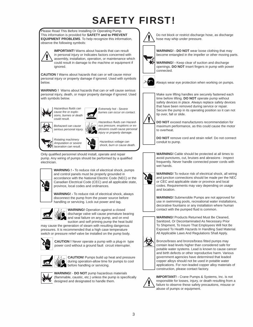
Please Read This Before Installing Or Operating Pump. This information is provided for SAFETY and to PREVENT EQUIPMENT PROBLEMS. To help recognize this information, observe the following symbols:
IMPORTANT! Warns about hazards that can result in personal injury or Indicates factors concerned with assembly, installation, operation, or maintenance which could result in damage to the machine or equipment if ignored.
CAUTION ! Warns about hazards that can or will cause minor personal injury or property damage if ignored. Used with symbols below.
WARNING ! Warns about hazards that can or will cause serious personal injury, death, or major property damage if ignored. Used with symbols below.
Only qualifi ed personnel should install, operate and repair pump. Any wiring of pumps should be performed by a qualifi ed electrician.
WARNING ! - To reduce risk of electrical shock, pumps and control panels must be properly grounded in accordance with the National Electric Code (NEC) or the Canadian Electrical Code (CEC) and all applicable state, province, local codes and ordinances.
WARNING! - To reduce risk of electrical shock, always disconnect the pump from the power source before handling or servicing. Lock out power and tag.
WARNING! Operation against a closed discharge valve will cause premature bearing and seal failure on any pump, and on end suction and self priming pump the heat build
may cause the generation of steam with resulting dangerous pressures. It is recommended that a high case temperature switch or pressure relief valve be installed on the pump body.
CAUTION ! Never operate a pump with a plug-in type power cord without a ground fault circuit interrupter.
CAUTION! Pumps build up heat and pressure during operation-allow time for pumps to cool before handling or servicing.
WARNING! - DO NOT pump hazardous materials (fl ammable, caustic, etc.) unless the pump is specifi cally designed and designated to handle them.
Do not block or restrict discharge hose, as discharge hose may whip under pressure.
WARNING! - DO NOT wear loose clothing that may become entangled in the impeller or other moving parts.
WARNING! - Keep clear of suction and discharge openings. DO NOT insert fi ngers in pump with power connected.
Always wear eye protection when working on pumps.
Make sure lifting handles are securely fastened each time before lifting. DO NOT operate pump without safety devices in place. Always replace safety devices that have been removed during service or repair. Secure the pump in its operating position so it can not tip over, fall or slide.
DO NOT exceed manufacturers recommendation for maximum performance, as this could cause the motor to overheat.
DO NOT remove cord and strain relief. Do not connect conduit to pump.
WARNING! Cable should be protected at all times to avoid punctures, cut, bruises and abrasions - inspect frequently. Never handle connected power cords with wet hands.
WARNING! To reduce risk of electrical shock, all wiring and junction connections should be made per the NEC or CEC and applicable state or province and local codes. Requirements may vary depending on usage and location.
WARNING! Submersible Pumps are not approved for use in swimming pools, recreational water installations, decorative fountains or any installation where human contact with the pumped fl uid is common.
WARNING! Products Returned Must Be Cleaned, Sanitized, Or Decontaminated As Necessary Prior To Shipment, To Insure That Employees Will Not Be Exposed To Health Hazards In Handling Said Material. All Applicable Laws And Regulations Shall Apply.
Bronze/brass and bronze/brass fi tted pumps may contain lead levels higher than considered safe for potable water systems. Lead is known to cause cancer and birth defects or other reproductive harm. Various government agencies have determined that leaded copper alloys should not be used in potable water applications. For non-leaded copper alloy materials of construction, please contact factory.
IMPORTANT! - Crane Pumps & Systems, Inc. is not responsible for losses, injury, or death resulting from a failure to observe these safety precautions, misuse or abuse of pumps or equipment.
SAFETY FIRST!
Hazardous fl uids can cause fi re or explo-sions, burnes or death could result.
Extremely hot - Severe burnes can occur on contact.
Biohazard can cause serious personal injury.
Hazardous fl uids can Hazard-ous pressure, eruptions or ex-plosions could cause personal injury or property damage.
Rotating machineryAmputation or severe laceration can result.
Hazardous voltage can shock, burn or cause death.
4
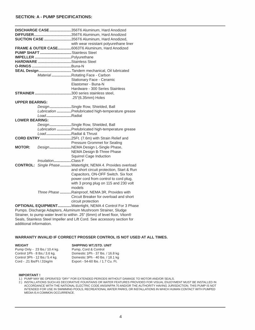
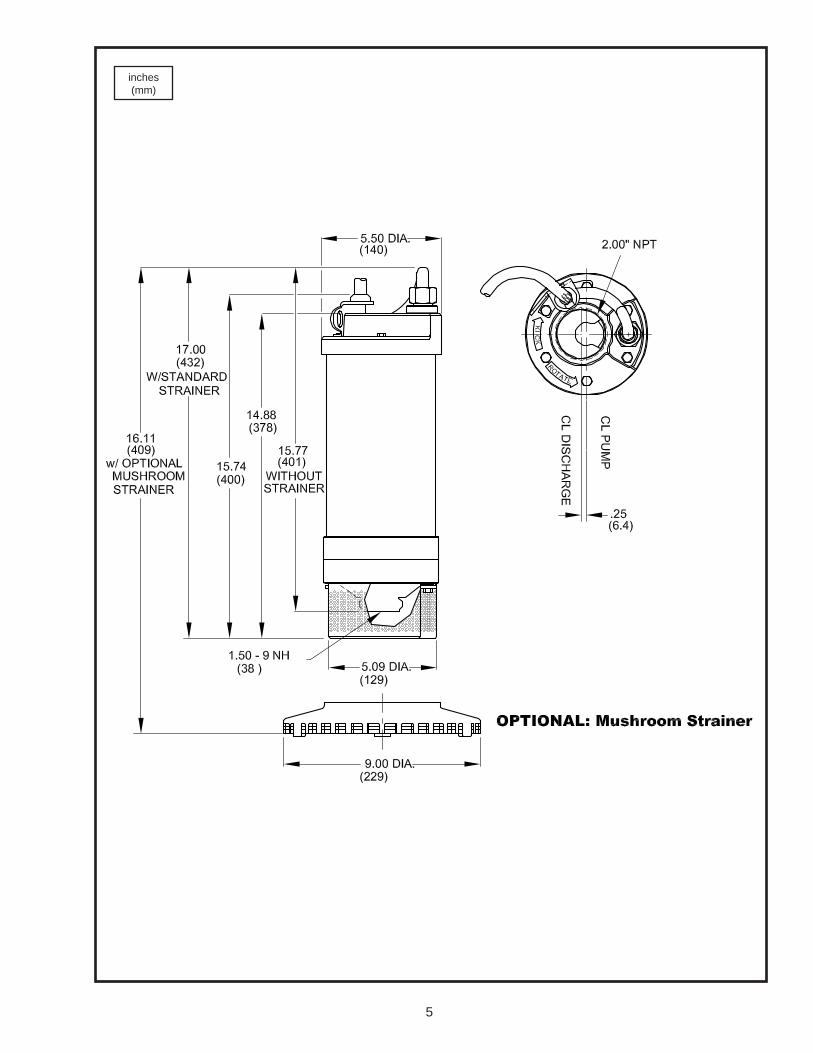
DISCHARGE CASE .....................356T6 Aluminum, Hard AnodizedDIFFUSER ....................................356T6 Aluminum, Hard AnodizedSUCTION CASE ..........................356T6 Aluminum, Hard Anodized, with wear resistant polyurethane linerFRAME & OUTER CASE .............6063T6 Aluminum, Hard AnodizedPUMP SHAFT ..............................Stainless SteelIMPELLER ...................................PolyurethaneHARDWARE ................................Stainless SteelO-RINGS ......................................Buna-NSEAL Design ............................... Tandem mechanical, Oil lubricated Material ...................Rotating Face - Carbon Stationary Face - Ceramic Elastomer - Buna-N Hardware - 300 Series StainlessSTRAINER ...................................300 series stainless steel, .25”(6.35mm) HolesUPPER BEARING: Design .....................Single Row, Shielded, Ball Lubrication ..............Prelubricated high-temperature grease Load ........................RadialLOWER BEARING: Design .....................Single Row, Shielded, Ball Lubrication ..............Prelubricated high-temperature grease Load ........................Radial & ThrustCORD ENTRY ..............................25Ft. (7.6m) with Strain Relief and Pressure Grommet for SealingMOTOR: Design .....................NEMA Design L-Single Phase, NEMA Design B-Three Phase Squirrel Cage Induction Insulation.................Class FCONTROL: Single Phase ...........Watertight, NEMA 4. Provides overload and short circuit protection, Start & Run Capacitors, ON-OFF Switch. Six foot power cord from control to cord plug, with 3 prong plug on 115 and 230 volt models Three Phase ...........Rainproof, NEMA 3R, Provides with Circuit Breaker for overload and short circuit protectionOPTIONAL EQUIPMENT .............Watertight, NEMA 4 Control For 3 PhasePumps. Discharge Adapters, Aluminum Mushroom Strainer, SludgeStrainer, to pump water level to within .25” (6mm) of level fl oor, Viton®Seals, Stainless Steel Impeller and Lift Cord. See accessory section foradditional information.
WARRANTY INVALID IF CORRECT PROSSER CONTROL IS NOT USED AT ALL TIMES.
WEIGHT SHIPPING WT./STD. UNITPump Only - 23 lbs./ 10.4 kg. Pump, Cord & ControlControl 1Ph - 8 lbs./ 3.6 kg. Domestic 1Ph - 37 lbs. / 16.8 kg Control 3Ph - 12 lbs./ 5.4 kg. Domestic 3Ph - 40 lbs. / 18.1 kgCord - .21 lbs/Ft /.31kg/m Export - 54-60 lbs. / 1.7 Cu. Ft.
SECTION: A - PUMP SPECIFICATIONS:
IMPORTANT !1.) PUMP MAY BE OPERATED “DRY” FOR EXTENDED PERIODS WITHOUT DAMAGE TO MOTOR AND/OR SEALS. 2.) INSTALLATIONS SUCH AS DECORATIVE FOUNTAINS OR WATER FEATURES PROVIDED FOR VISUAL ENJOYMENT MUST BE INSTALLED IN ACCORDANCE WITH THE NATIONAL ELECTRIC CODE ANSI/NFPA 70 AND/OR THE AUTHORITY HAVING JURISDICTION. THIS PUMP IS NOT INTENDED FOR USE IN SWIMMING POOLS, RECREATIONAL WATER PARKS, OR INSTALLATIONS IN WHICH HUMAN CONTACT WITH PUMPED MEDIA IS A COMMON OCCURRENCE.
5
inches(mm)
6
SECTION B: GENERAL INFORMATION
B-1) To the Purchaser:Congratulations! You are the owner of one of the fi nest pumps on the market today. These pumps are products engineered and manufactured of high quality components. Over one hundred years of pump building experience along with a continuing quality assurance program combine to produce a pump which will stand up to the toughest applications.
This manual will provide helpful information concerning installation, maintenance, and proper service guidelines.
B-2) Receiving:Upon receiving the pump, it should be inspected for damage or shortages. If damage has occurred, fi le a claim immediately with the company that delivered the pump. If the manual is removed from the packaging, do not lose or misplace.
B-3) Storage:Short Term - Prosser Pumps are manufactured for effi cient performance following short inoperative periods in storage. For best results, pumps can be retained in storage, as factory assembled, in a dry atmosphere with constant temperatures for up to six (6) months.
Long Term - Any length of time exceeding six (6) months, but not more than twenty four (24) months. The units should be stored in a temperature controlled area, a roofed over walled enclosure that provides protection from the elements (rain, snow, wind-blown dust, etc.), and whose temperature can be maintained between +40 deg. F and +120 deg. F.If extended high humidity is expected to be a problem, all exposed parts should be inspected before storage and all surfaces should then be sprayed with a rust-inhibiting oil.
Pump should be stored in its original shipping container. On initial start up, rotate impeller by hand to assure seal and impeller rotate freely. If it is required that the pump be installed and tested before the long term storage begins, such installation will be allowed provided:
1.) The pump is not installed under water for more than one (1) month.2.) Immediately upon satisfactory completion of the test, the pump is removed, thoroughly dried, repacked in the original shipping container, and placed in a temperature controlled storage area.
B-4) Service Centers:For the location of the nearest Prosser Service Center, check your Prosser Pumps representative or Crane Pumps & Systems, Inc. Service Department in Piqua, Ohio, telephone (937) 778-8947. or Crane Pumps & Systems Canada, Bramton, Ontario, (905) 457-6223.
SECTION C: INSTALLATIONC-1) Location:These pumping units are self-contained and are recommended for well type pre-dewatering of building sites or pipelines, sumping and dewatering of coffer dams, caissons and tunnels, for dewatering of manholes and transformer vaults, construction sites and for emergency service, for shipboard dewatering of cargo holds and tanks, for damage control or ballast transfer and for general use in shipyards, dry-docks or off-shore rigs.
Before pumping fl uids other than water, consult the factory, giving fl uid, fl uid temperature, specifi c gravity, viscosity, capacity in USGPM and total head and/or pressure requirements, including friction loss through discharge line, fi ttings, valves, etc. Maximum fl uid temperature for sustained operation is 104°F (40°C) at specifi c gravity 1.0. Pump may run dry for reasonable period in air without damage where air can circulate freely through pump. DO NOT allow pump to be buried in mud or sand.
IMPORTANT! - Pump should have strainer affi xed at all times. Inspect and clean the pump strainer periodically for maximum effi ciency and
performance.
C-2) Discharge:Discharge hose is recommended. If rigid pipe is used, install so that there is no weight or strain on the pump.
C-2.1) Series Connection: (Optional)The In-Line suction and discharge permits multiple pumps to be operated in series where the discharge of one pump is directly connected to the suction of another with the use of an adapter kit. Two small pumps instead of one large one enables the user to meet high head requirements on one job and separate the pumps to meet lower head requirements on the next.
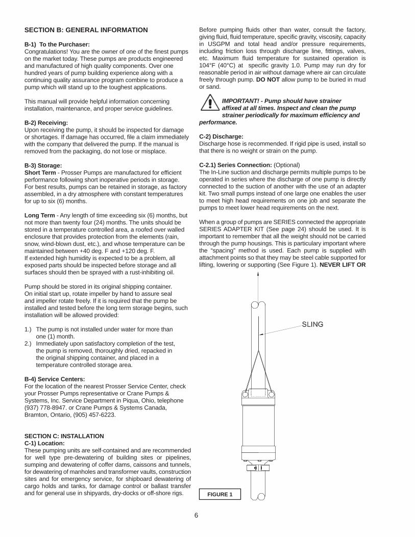
When a group of pumps are SERIES connected the appropriate SERIES ADAPTER KIT (See page 24) should be used. It is important to remember that all the weight should not be carried through the pump housings. This is particulary important where the “spacing” method is used. Each pump is supplied with attachment points so that they may be steel cable supported for lifting, lowering or supporting (See Figure 1). NEVER LIFT OR
FIGURE 1

7
SUPPORT THE PUMP BY ITS ELECTRICAL CABLE ! Each pump must be treated as an individual unit as far as cabling and overload protection is concerned. Individual cables must be run up to each pump controller for proper protection. Provide suitable protection for the cable rubbing against the caisson. This is particularly important around the pump housing of the upper pumps. PVC pipe or steel braiding may be in order in extreme cases of tight clearances. Some have crimped (both
ends) stove pipe around the cable and pump (See Fig. 2).Check valves in a clean system where no or small amounts of solids are entrained, will not be troublesome. If they leak, no harm will be done. It should be noted that substantial amounts of solids will tend to block check valves after shutdown. If check valves are placed in an “S” bend ABOVE the lowest point, solids
will drop out below the valve (See Fig. 3).C-2.2) Series Connection of Dissimilar Pumps: (Optional)In some cases where high heads and relatively low-fl ow rates are desired at the most economic cost, two or more different size pumps may be used. IT IS VERY IMPORTANT THAT THE FLOW RATE PRODUCED IS WITHIN THE CAPACITY OF THE SMALLER PUMP, PUMP B. If the system is fl owing more than the smaller pump can handle, i.e., greater than Q, the smaller pump, Pump B, will actually retard the fl ow, and can induce cavitation in Pump A. To predict the performance, simply add the heads produced at a particular fl ow rate, HT = HA + HB.
(See Fig. 4).
C-3) Liquid Level Controls: (If Applicable)Attach “ON” fl oat to discharge hose or pump cable at desired pump “ON” level. Attach “OFF” fl oat to discharge hose or pump cable at desired pump “OFF” level. The “OFF” fl oat must be below the “ON” fl oat. To attach the fl oats, thread the cable strap through the buckle with the ratchet pawl, cinch up tight, thread excess strapping through outer buckle slot. Be certain that the level controls cannot hang up or foul in it’s swing. It is recommended that the pump is completely submerged when the level control is in the “Off” mode.
C-4) Galvanic Protection Kit: (If Applicable)For protection against Electrolytic action, whether in saltwater or in other reactionary applications, the Galvanic Protection Kit is a proven method for protecting the pump against corrosion by using a Zinc Anode fi tted to the pump. See page 23.
C-5) Electrical Cables:
WARNING! - All model pumps and control panels must be properly grounded per THE NATIONAL ELECTRIC CODE or CANADIAN ELECTRIC CODE, STATE, PROVINCE and LOCAL CODES. Improper grounding voids warranty.
C-5.1) Power Cable:The cord assembly mounted to the pump must not be modifi ed in any way except for shortening to a specifi c application. Any splice between the pump and the control panel must be made in accordance with all applicable electric codes. Install and pull pumps only by attaching a rope or cable to the lifting lugs or handles provided on the pump. Cable should be protected at all times to avoid punctures and cuts. Do not use the power cable to lift pump. DO NOT DROP PUMPS !
FIGURE 2
FIGURE 3
FIGURE 4

8
PUMP SERIES MAX CORD SIZE9-01011 100Ft./30.5m9-01012 375Ft./114.3m9-01032 715Ft./217.9m9-01034 2860Ft./871.7m9-01035 4595Ft./1400.5m9-01311 90Ft.27.4m9-01312 325Ft./99.1m9-01332 675Ft./205.7m9-01334 2705Ft./824.4m9-01335 4290Ft./1307.5m
C-5.2) Wire Size:Transmission of power from source to pump control should be accomplished with suffi ciently large 4 conductor cable of heavy duty type to prevent excessive voltage drop under full load conditions. Voltage supplied to pump must not vary more than plus or minus 10% of rated pump voltage, measured at motor terminal. Voltage must be balanced phase to phase within 5%. See above table for electrical information.
C-5.3) Overload Protection:C-5.3-1) Single Phase units utilize fuses in the control box for protection against motor damage due to locked rotor conditions and short circuits. A switch is provided for manual “ON - OFF” control. Before restarting pumps, check for correct voltage and phase. Also check for short circuits, cuts or breaks in cable and that connections are tight. Then if pump still won’t start, pull unit for inspection. DO NOT LET THE PUMP CYCLE OR RUN IF AN OVERLOAD CONDITION OCCURS !
C-5.3-2) Three Phase- units control boxes utilizes a circuit breaker for pump overload, locked rotor or short circuit conditions and will disconnect the power to the pump if any of these conditions occur. Before restarting pumps, check for correct voltage and phase. Also check for short circuits, cuts or breaks in cable and that connections are tight. Then if pump still won’t start, pull unit for inspection. DO NOT LET THE PUMP CYCLE OR RUN IF AN OVERLOAD CONDITION OCCURS !
IMPORTANT ! - Avoid repeated attempts to start motor. If motor fails to start after two attempts, pull pump and correct problem.
C-6) Control - Mount the control above the ground to avoid seepage of dirt and water into control. This is critical or damage may occur. Control enclosure must be operated with cover closed.
SECTION D: START-UP OPERATIOND-1) Check Voltage and Phase:Before operating pump, compare the voltage and phase information stamped on the pump’s identifi cation plate to the available power. Install proper safety ground connection to the green conductor to insure the motor, pump and control remains at ground potential, independent of the power supply. A metal well casing is one of the best available. Use voltmeter to make certain that voltage at pump control is within ±10% of the rated voltage shown on the pump nameplate.
D-2) Check Pump Rotation:Before putting pump into service for the fi rst time, the motor rotation must be checked. Improper motor rotation can result in poor pump performance and can damage the motor and/or pump. To check the rotation, suspend the pump freely, momentarily apply power and observe the “kick”. “Kick” should always be in a clockwise direction as viewed from the top of the pump motor housing. Pump “Kick” is the opposite direction of pump rotation.
D-2.1) Incorrect Rotation for Three-Phase Pumps:In the event that the rotation is incorrect for a three-phase installation, interchange any two power cable leads at the control box. DO NOT change leads in the cable housing in the motor. Recheck the “kick” rotation again by momentarily applying power.
D-2.2) Incorrect Rotation for Single-Phase Pumps:In the unlikely event that the rotation is incorrect for a single
phase pump, contact a Prosser Service Center.
WARNING ! - DO NOT operate pump in reverse rotation as damage may result.
D-3) Start-Up:DO NOT attempt to start a frozen pump. Instead, submerge pump in water for twenty (20) minutes before starting. DO NOT attempt to thaw a frozen pump with a torch. Start pumps one at a time to avoid excessive current draw on power supply. When starting up pumps connected in series, turn on the bottom pump fi rst, then the next to the bottom, etc (See Fig 5). When shutting down, turn off the top pump fi rst and continue downward after allowing suffi cient time for the water column to drain down to the next lower pump. This process reduces the chance of over-pressuring the lower seals when there are no system check valves or the units are spaced.
FIGURE 5

9
PART NO. HP VOLT/PH Hz RPM(Nom.)
NEMASTARTCODE
FULLLOADAMPS
LOCKEDROTORAMPS
CORDSIZE
CORDTYPE
CORDO.D.
WINDINGRESISTANCE
W,B - R,B - R,WPUMP w/WATERTIGHT CONTROL9-01011-28FK .75 115/1 60 3450 G 11.0 36.2 14/4 SOW 0.570 (14.5) 1.5 - 6.2 - 4.7
9-01012-28FK .75 230/1 60 3450 G 5.8 18.1 14/4 SOW 0.570 (14.5) 6.0 - 7.6 - 7.6
9-01032-24FK .75 230/3 60 3450 J 3.6 15.0 14/4 SOW 0.570 (14.5) 8.5 - 8.5 - 8.5
9-01034-24FK .75 460/3 60 3450 J 1.8 7.5 14/4 SOW 0.570 (14.5) 34.2 - 34.2 - 34.2
9-01035-24FK .75 575/3 60 3450 K 1.4 6.2 14/4 SOW 0.570 (14.5) 54.4 - 54.4 - 54.4
9-01311-28FK 1.0 115/1 60 3450 D 12.0 36.2 14/4 SOW 0.570 (14.5) 1.5 - 6.2 - 4.7
9-01312-28FK 1.0 230/1 60 3450 D 6.7 18.1 14/4 SOW 0.570 (14.5) 6.0 - 7.6 - 7.6
9-01332-24FK 1.0 230/3 60 3450 G 3.8 15.0 14/4 SOW 0.570 (14.5) 8.5 - 8.5 - 8.5
9-01334-24FK 1.0 460/3 60 3450 G 1.9 7.5 14/4 SOW 0.570 (14.5) 34.2 - 34.2 - 34.2
9-01335-24FK 1.0 575/3 60 3450 G 1.5 6.2 14/4 SOW 0.570 (14.5) 54.4 - 54.4 - 54.4
PUMP w/RAINPROOF CONTROL9-01032-23FK .75 230/3 60 3450 J 3.6 15.0 14/4 SOW 0.570 (14.5) 8.5 - 8.5 - 8.5
9-01034-23FK .75 460/3 60 3450 J 1.8 7.5 14/4 SOW 0.570 (14.5) 34.2 - 34.2 - 34.2
9-01035-23FK .75 575/3 60 3450 K 1.4 6.2 14/4 SOW 0.570 (14.5) 54.4 - 54.4 - 54.4
9-01332-23FK 1.0 230/3 60 3450 G 3.8 15.0 14/4 SOW 0.570 (14.5) 8.5 - 8.5 - 8.5
9-01334-23FK 1.0 460/3 60 3450 G 1.9 7.5 14/4 SOW 0.570 (14.5) 34.2 - 34.2 - 34.2
9-01335-23FK 1.0 575/3 60 3450 G 1.5 6.2 14/4 SOW 0.570 (14.5) 54.4 - 54.4 - 54.4
Pump rated for operation at ± 10% voltage at motor. Winding Resistance ±5%.
PART NO.50Hz
HP(kW)
VOLT PH Hz RPM(Nom.)
NEMASTARTCODE
FULLLOADAMPS
LOCKEDROTORAMPS
CORDSIZE
CORDTYPE
CORDO.D.
WINDINGRESISTANCE
W,B - R,B - R,WPUMP w/WATERTIGHT CONTROL
9-01312-28FK-50 .56 (.42) 230 1 50 2850 D 6.7 18.1 14/4 SOW 0.570 (14.5) 6.0 - 7.6 - 7.6
9-01332-24FK-50 .56 (.42) 230 3 50 2850 G 3.8 15.0 14/4 SOW 0.570 (14.5) 8.5 - 8.5 - 8.5
PUMP w/RAINPROOF CONTROL
9-01332-23FK-50 .56 (.42) 230 3 50 2850 G 3.8 15.0 14/4 SOW 0.570 (14.5) 8.5 - 8.5 - 8.5
CAUTION! - When check valves are not used and a series system is accidentally shut down instantaneously (power failure), suffi cient time must be allowed for pump impellers to stop rotating
backwards before restarting.
NOTE: Pressure inside 3” discharge pumps or smaller should not exceed 100 PSI (231 ft of Head). Pressure inside 4” discharge pumps or larger should not exceed 200 PSI (462 ft. of Head).
D-3.1) Report:Included at the end of this manual are two start-up report sheets, these sheets are to be completed as applicable. Return one copy to the Crane Pumps & Systems Service Department and store the second in the control panel or with the pump manual if no control panel is used. It is important to record this data at initial start-up since it will be useful to refer to should servicing the pump be required in the future.
D-3.2) Identifi cation Plate:Record the numbers from the pump’s identifi cation plate on both START-UP REPORTS provided at the end of the manual for future reference.
D-3.3) Insulation Test:Before the pump is put into service, an insulation (megger) test should be performed on the motor. The resistance values (ohms) as well as the voltage (volts) and current (amps) should be recorded on the start-up report.
10
SECTION E: PREVENTIVE MAINTENANCE:Prosser pumps are CSA approved. The following procedure must be followed to assure proper pump operation and unit CSA approval integrity.
1.) General Safety: Frequent inspection shall be made. All electrical parts, including the portable cable and wiring, shall be kept in a safe condition. KEEP CABLE GLAND NUTS TIGHT, CHECK FREQUENTLY. There shall be no openings into the casing of the electrical parts. The machine frame shall be effectively grounded. The power wires shall not be used for grounding. The operating voltage shall match the voltage rating of the motor(s).
2.) Servicing: Pump and control enclosures shall be restored to the state of original safety with respect to all lead entrances, etc., following disassembly.
3.) Renewals and Repairs: Special care shall be taken in making renewals or repairs. Leave no parts off. Use replacement parts furnished by the manufacturer. When any lead entrance is disturbed, the original leads or exact duplicates thereof shall be used.
4.) Fastenings: All bolts, nuts, screws and other means of fastenings and also threaded covers, shall be in place, properly tightened and secured.
5.) Cable Requirements: A heavy usage, type SOW submersible cable shall be used. Special care shall be taken in handling the cable against mechanical injury and wear. Connections and wiring to the power source shall be in accordance with all local electrical and safety codes.
6.) Shaft Seals: The seals should be inspected every 400 or 500 operating hours for wear (more often if abrasives are present). To make a quick check of the seal’s condition, drain and inspect the oil in the seal chamber (See Section F-1). If oil removed from the pump contains water or abrasives, replace seals.
7.) Amperage: Amperage should be checked periodically (at least weekly) to be certain that it does not exceed limits recommended by manufacturer on pump nameplate.
8.) Volts: If a generator is the power source, check daily for variation of voltage and cycles.
This pump is equipped with prelubricated bearings.
When a job is completed and before pumps are stored, drain the oil from the seal chamber (a must before freezing weather). If dirt or water are found in the oil, replace seals, bearings, lower “O” rings and oil.
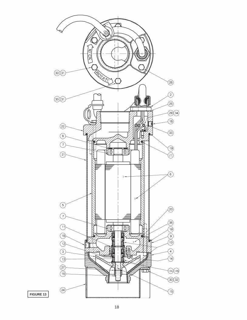
SECTION F: SERVICE AND REPAIRNOTE: All item numbers in ( ) refer to Figures 13 & 14.
WARNING! - Electrical power to the pump motors must be disconnected and locked out to prevent any dangerous electrical hazards or personnel danger before any service work is done to the pump.
F-1) Electrical Inspection:When pumps are returned from a fi eld operation, or when a pump needs repair, prior to disassembly, and after disconnecting the unit from the power source, make electrical inspection of the pump, cable and control box. The test can be done by using a megger and an ohmmeter.
F-1.1) Insulation Resistance - Cord & Control:Use the megger to measure the insulation resistance. Attach the megger probes to the pump lead side of the circuit breaker in the control box, one probe to the ground lead and one probe to a pump power lead. Acceptable values of insulation resistance are 10 megohms or greater. If insulation resistance is below 10 megohms, the motor leads should be disconnected from the cord assembly so that the cord and motor can be tested separately.
Should the cord show insulation resistance of less than 10 megohms, disconnect from control box and attach megger probes to the individual leads within the cord. Values below 10 megohms of insulation resistance would indicate damage or moisture and cord should be replaced. Low values of insulation resistance below 10 megohms for the circuitry within the control box would indicate damage or moisture, Any bad parts should be replaced.
F-1.2) Insulation Resistance - Motor:The insulation resistance of the motor stator can be measured by attaching one probe of the megger to the motor power leads and the other probe to the motor ground lead or to bare metal of the pump frame. Insulation resistance values under 10 megohms would indicate presence of excessive moisture within the stator winding. Such moisture can be removed from the stator by placing the stator and frame assembly in an oven and baking the assembly at 250°- 275°F for two to three hours. Following such baking, remeasure the insulation resistance to verify that a minimum of 10 megohms has been attained, if not, replace stator.
WARNING ! - Always wear appropriate clothing and safety gear when working with or around oven.
If low stator insulation resistance is due to other modes of failure, such as damaged leads, deformed end turns, etc, the stator should be replaced. Another test of the electrical integrity of the stator is the measurement of winding resistance with an ohmmeter. Such measurement is made between the leads of the stator. If the resistance of the stator winding is greater than listed on page 9, the stator should be replaced.
F-2) Lubrication:F-2.1) Checking Oil:To check oil, remove pipe plug (18) from diffuser (9). With a fl ashlight, visually inspect the oil in the seal cavity to make sure it is clean and clear, light amber in color and free from suspended particles. Milky white oil indicates the presence of water. If the the oil looks milky white, pour the oil out of the oil chamber and let it settle in a clean, dry container. If any water settles out in the bottom of the container or if the oil is white and thick (emulsifi ed) replace rotary shaft seals (See Section F-4) and oil.
11
You can also check oil for contamination by using an oil tester with a range to 30 Kilovolts breakdown. If oil is found to be clean and uncontaminated (measure at or above 15 KV. breakdown), refi ll the seal cavity. If oil is found to be dirty or contaminated (or measures below 15 KV. breakdown), replace rotary seals and oil.
TABLE 1 - SEAL CHAMBER OILSUPPLIER GRADE
Gulf (334206) Harmony 68Texaco URSA P-68
F-2.2) Replacing Oil:Remove pipe plug (18) from diffuser (9), and drain oil from seal chamber and dispose of properly. Flush inside seal chamber of diffuser (9) thoroughly to be sure it is clean and free of abrasives. Refi ll oil chamber with 3 0z (90 ml), or about half full, of a 20W non-detergent turbine oil with rust and oxidation inhibitors. After replacing oil, replace pipe plug (18) using a sealant.
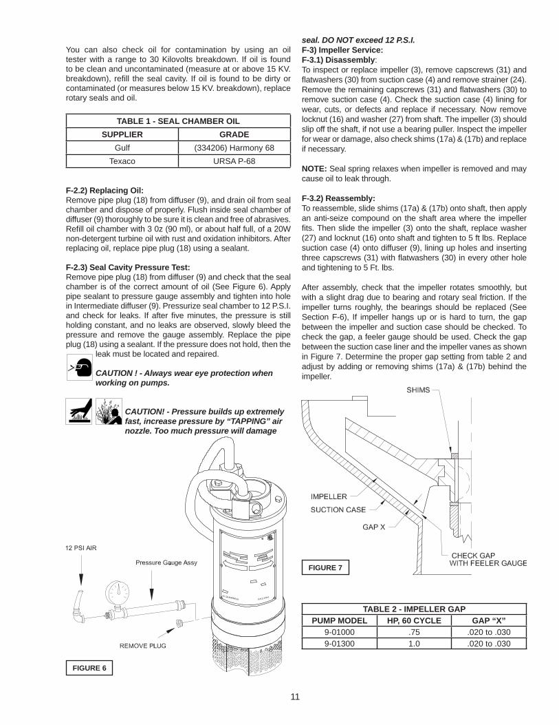
F-2.3) Seal Cavity Pressure Test:Remove pipe plug (18) from diffuser (9) and check that the seal chamber is of the correct amount of oil (See Figure 6). Apply pipe sealant to pressure gauge assembly and tighten into hole in Intermediate diffuser (9). Pressurize seal chamber to 12 P.S.I. and check for leaks. If after fi ve minutes, the pressure is still holding constant, and no leaks are observed, slowly bleed the pressure and remove the gauge assembly. Replace the pipe plug (18) using a sealant. If the pressure does not hold, then the
leak must be located and repaired.
CAUTION ! - Always wear eye protection when working on pumps.
CAUTION! - Pressure builds up extremely fast, increase pressure by “TAPPING” air nozzle. Too much pressure will damage
seal. DO NOT exceed 12 P.S.I.F-3) Impeller Service:F-3.1) Disassembly:To inspect or replace impeller (3), remove capscrews (31) and fl atwashers (30) from suction case (4) and remove strainer (24). Remove the remaining capscrews (31) and fl atwashers (30) to remove suction case (4). Check the suction case (4) lining for wear, cuts, or defects and replace if necessary. Now remove locknut (16) and washer (27) from shaft. The impeller (3) should slip off the shaft, if not use a bearing puller. Inspect the impeller for wear or damage, also check shims (17a) & (17b) and replace if necessary.
NOTE: Seal spring relaxes when impeller is removed and may cause oil to leak through.
F-3.2) Reassembly:To reassemble, slide shims (17a) & (17b) onto shaft, then apply an anti-seize compound on the shaft area where the impeller fi ts. Then slide the impeller (3) onto the shaft, replace washer (27) and locknut (16) onto shaft and tighten to 5 ft lbs. Replace suction case (4) onto diffuser (9), lining up holes and inserting three capscrews (31) with fl atwashers (30) in every other hole and tightening to 5 Ft. lbs.
After assembly, check that the impeller rotates smoothly, but with a slight drag due to bearing and rotary seal friction. If the impeller turns roughly, the bearings should be replaced (See Section F-6), If impeller hangs up or is hard to turn, the gap between the impeller and suction case should be checked. To check the gap, a feeler gauge should be used. Check the gap between the suction case liner and the impeller vanes as shown in Figure 7. Determine the proper gap setting from table 2 and adjust by adding or removing shims (17a) & (17b) behind the impeller.
TABLE 2 - IMPELLER GAPPUMP MODEL HP, 60 CYCLE GAP “X”
9-01000 .75 .020 to .0309-01300 1.0 .020 to .030
FIGURE 6
FIGURE 7
12
Inspect strainer (24) and clean, making sure hole are not clogged to ensure unrestricted fl ow. Now position strainer (24) onto suction case (4) and inserting three capscrews (31) with fl atwashers (30) in holes in suction case and tightening to 5 Ft. lbs.
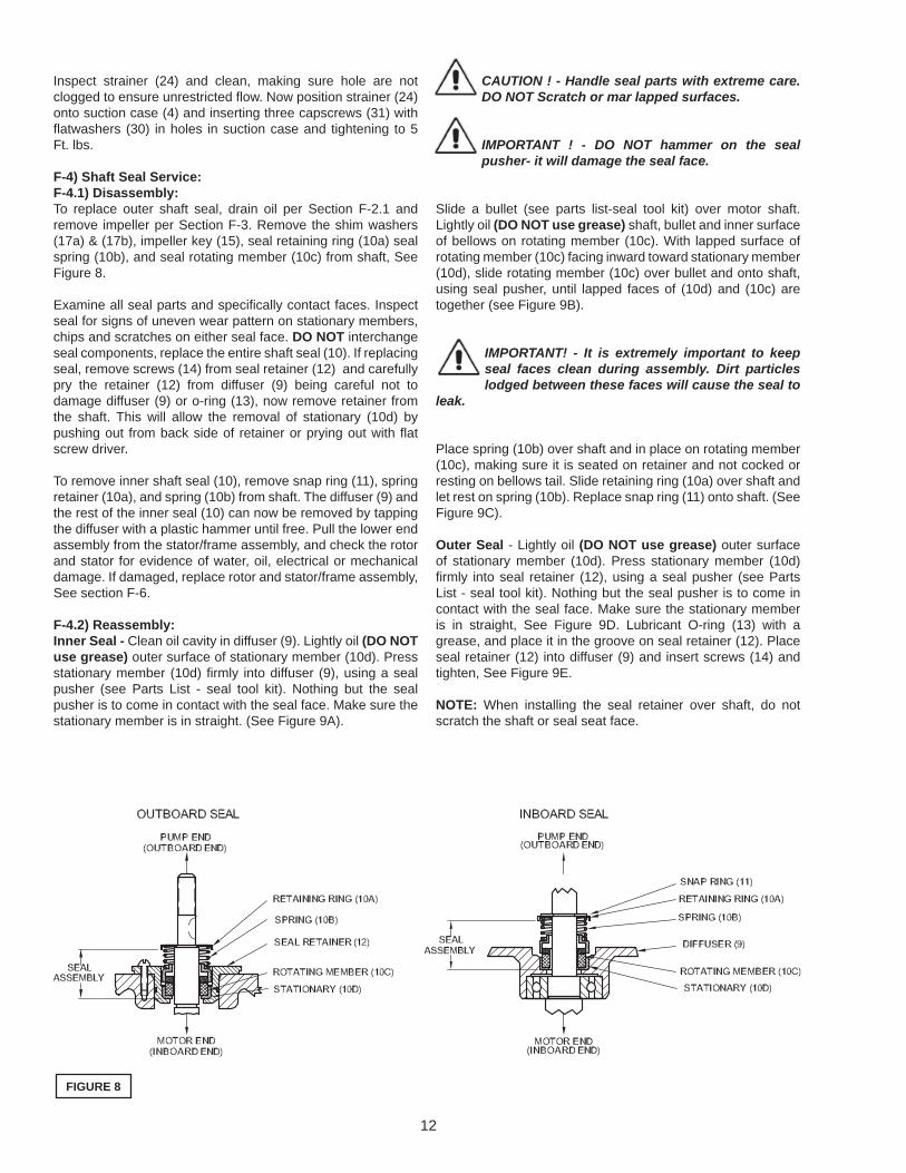
F-4) Shaft Seal Service:F-4.1) Disassembly:To replace outer shaft seal, drain oil per Section F-2.1 and remove impeller per Section F-3. Remove the shim washers (17a) & (17b), impeller key (15), seal retaining ring (10a) seal spring (10b), and seal rotating member (10c) from shaft, See Figure 8.
Examine all seal parts and specifi cally contact faces. Inspect seal for signs of uneven wear pattern on stationary members, chips and scratches on either seal face. DO NOT interchange seal components, replace the entire shaft seal (10). If replacing seal, remove screws (14) from seal retainer (12) and carefully pry the retainer (12) from diffuser (9) being careful not to damage diffuser (9) or o-ring (13), now remove retainer from the shaft. This will allow the removal of stationary (10d) by pushing out from back side of retainer or prying out with fl at screw driver.
To remove inner shaft seal (10), remove snap ring (11), spring retainer (10a), and spring (10b) from shaft. The diffuser (9) and the rest of the inner seal (10) can now be removed by tapping the diffuser with a plastic hammer until free. Pull the lower end assembly from the stator/frame assembly, and check the rotor and stator for evidence of water, oil, electrical or mechanical damage. If damaged, replace rotor and stator/frame assembly, See section F-6.
F-4.2) Reassembly:Inner Seal - Clean oil cavity in diffuser (9). Lightly oil (DO NOT use grease) outer surface of stationary member (10d). Press stationary member (10d) fi rmly into diffuser (9), using a seal pusher (see Parts List - seal tool kit). Nothing but the seal pusher is to come in contact with the seal face. Make sure the stationary member is in straight. (See Figure 9A).
CAUTION ! - Handle seal parts with extreme care. DO NOT Scratch or mar lapped surfaces.
IMPORTANT ! - DO NOT hammer on the seal pusher- it will damage the seal face.
Slide a bullet (see parts list-seal tool kit) over motor shaft. Lightly oil (DO NOT use grease) shaft, bullet and inner surface of bellows on rotating member (10c). With lapped surface of rotating member (10c) facing inward toward stationary member (10d), slide rotating member (10c) over bullet and onto shaft, using seal pusher, until lapped faces of (10d) and (10c) are together (see Figure 9B).
IMPORTANT! - It is extremely important to keep seal faces clean during assembly. Dirt particles lodged between these faces will cause the seal to
leak.
Place spring (10b) over shaft and in place on rotating member (10c), making sure it is seated on retainer and not cocked or resting on bellows tail. Slide retaining ring (10a) over shaft and let rest on spring (10b). Replace snap ring (11) onto shaft. (See Figure 9C).
Outer Seal - Lightly oil (DO NOT use grease) outer surface of stationary member (10d). Press stationary member (10d) fi rmly into seal retainer (12), using a seal pusher (see Parts List - seal tool kit). Nothing but the seal pusher is to come in contact with the seal face. Make sure the stationary member is in straight, See Figure 9D. Lubricant O-ring (13) with a grease, and place it in the groove on seal retainer (12). Place seal retainer (12) into diffuser (9) and insert screws (14) and tighten, See Figure 9E.
NOTE: When installing the seal retainer over shaft, do not scratch the shaft or seal seat face.
FIGURE 8

13
FIGURE 9

14
Slide a bullet (see parts list-seal tool kit) over motor shaft. Lightly oil (DO NOT use grease) shaft, bullet and inner surface of bellows on rotating member (10c). With lapped surface of rotating member (10c) facing inward toward stationary member (10d), slide rotating member (10c) over bullet and onto shaft, using seal pusher, until lapped faces of (10d) and (10c) are together (see Figure 9F). Place spring (10b) over shaft and in place on rotating member (10c), making sure it is seated on retainer and not cocked or resting on bellows tail. Slide retaining ring (10a) over shaft and let rest on spring (10b), See Figure 9G. Assemble impeller, suction case and screen per Section F-3.2. Replace oil as outlined in paragraph F-2.2.
F-5) Discharge & Cord Service:F-5.1) Disassembly:Refer to Section F-1 before disassembly. While disassembling, check for indications of water leaks. Remove capscrews (28), cord gland assembly (2) and gasket (25) from discharge head (22). Use care to avoid damaging the metal surface. Disconnect cord wires from stator leads by removing connectors (29) and (34), being sure that the stator’s wires are identifi ed before disconnecting. Check wires for breaks or cuts. If water is present, there may be leakage through the cord gland (2e), o-rings (19) and (20), the power cord (2a) if it has been cut, or the shaft seals (10). Check all items and replace if needed. Remove ground screw (33) from discharge head (22).
Remove capscrews (31) and fl at washers (30) from discharge head (22). Carefully, using a plastic hammer, tap the discharge case (22) free from the frame assembly and remove while feeding the stator wires through the terminal cavity in the discharge case. Now remove o-rings (19) and (20), replace o-rings showing any nicks, cuts, cracks, or deformation.
To remove cable (2a), loosen cable grip nut (2b), cable grip washer (2c) and bushing (2d) and remove from cable, then Feed cable through strain relief bushing (2f). Check Strain relief bushing (2f) for damage and replace if necessary. (See Figure
10).
F-5.2) Reassembly:To assemble discharge case (22) to stator/frame assembly, set the assembly in the upright position. Make sure all stator leads are properly identifi ed (See Figure 11). Each lead should be color coded or numbered for identifi cation. Apply a grease to o-rings (19) and (20) and place on discharge case (22). Set the discharge case (22) onto the stator/frame assembly with the terminal cavity directly over the stator leads and insert the leads through the cavity opening, being careful not to lose the lead identifi cation numbers or damage the o-rings. Be sure that load spring (8) is sitting properly in bearing bore of discharge case. Line up the holes and insert capscrews (31) with fl atwashers (30) into holes and torque to 75 In Lbs.
FIGURE 10
FIGURE 11

15
If cord is being replaced, feed approximately 13” of cord though strain relief bushing (2f). Slide cable grip nut (2b), cord grip washer (2c), bushing (2d) and cord gland (2e) and gasket (25) onto cord (2a), and expose approximately 3” of wire at the end of the cord. Attach ground screw (33) with ground wire (Green) to the inside of terminal cavity in discharge case (22). Make wire connections in accordance to Figure 11 using connectors (29) and (34) and then tape each connector individually with electrical tape. Fold and insert the connectors and wires into the terminal box cavity. Apply Permatex® No. 2 to the surfaces of the discharge case (22) and cable gland (2e). Place gasket (25) on the discharge case and then place cable gland (2e) onto gasket and discharge case. Insert capscrews (28) and tighten to 5 Ft. Lbs.
Move Bushing (2d), washer (2c) and gland nut (2b) into place and tighten to 14 Ft. Lbs. After assembly, an insulation test (or MEGGER) should be performed per section F-1.1.
F-6) Motor and Bearing Service:F-6.1) Disassembly:To service or replace motor and/or bearings, fi rst remove discharge case (22) per Section F-5.1 and lower pump end per Section F-4.1. Remove rotor from stator, and bearings (7) and loading spring (8) from rotor shaft. Use a bearing puller if needed. Bearings that feel rough, show wear or rust should be replaced. If stator needs replaced, replace stator and frame assembly.
F-6.2) Reassembly:Set the stator/frame assembly and the discharge case in a vertical position with the discharge case down. Slip the outer case (21) over the frame (5). Press bearings (7) onto rotor shaft and assemble into stator/frame assembly. Place o-rings (19) and (20), and bearing spring (8) onto discharge case (22). Assemble discharge case onto motor/frame assembly per Section F-5.2 and Pump lower end per Section F-4.2. An electrical inspection should be performed after reassembly per Section F-1.
F-7 Motor Chamber Pressure Test:After fi nal assembly, pressure test the motor chamber by removing pipe plug (18) from discharge case (22) and connect an air hose fi tting into the pipe thread. Submerge the pump
completely and apply 12 PSI air pressure, see Figure 12.
WARNING! - DO NOT exceed 12 PSI air pressure.
Pump must not show any leakage, if leakage occurs, determine location and replace defective or damaged parts, then retest pump. After pump has been tested and no leaks have been
FIGURE 13

16
found, remove air hose connection and replace pipe plug (18) using a sealent, into discharge case (22).SECTION: G REPLACEMENT PARTSG-1 ORDERING REPLACEMENT PARTS:Your local Prosser distributor can supply parts and repair service. When ordering parts, ALWAYS furnish the following information: Specify pump model number as shown on nameplate, serial number, part number, item number and part name.
1. Pump serial number. (G-1)2. Pump model number. (G-2)4. Part description.5. Item part number.6. Quantity required.7. Shipping instructions.8. Billing Instructions.
G-1 SERIAL NUMBER:The Serial Number block will consists of a six digit number, which is specifi c to each pump and may be preceded by a alpha character, which indicates the plant location. This number will also be suffi xed with a three or four digit number, which indicates the date the unit was built (Date Code).EXAMPLE: A012345 495Reference the six digit portion (Serial Number) of the number when referring to the product.
G-2 MODEL NUMBER:This designation consist of numbers which represent, Pump Line, Horsepower, Motor phase, Voltage and Variations (as
shown below). This Number is used for ordering and obtaining information.
MODEL NUMBER DESIGATION9 - 0 XX X X
PROSSER
HORSEPOWER10 = .7513 = 1.0
VOLTAGE1 = 1152 = 2304 = 4605 = 575
PHASE1 = Single3 = Three
17
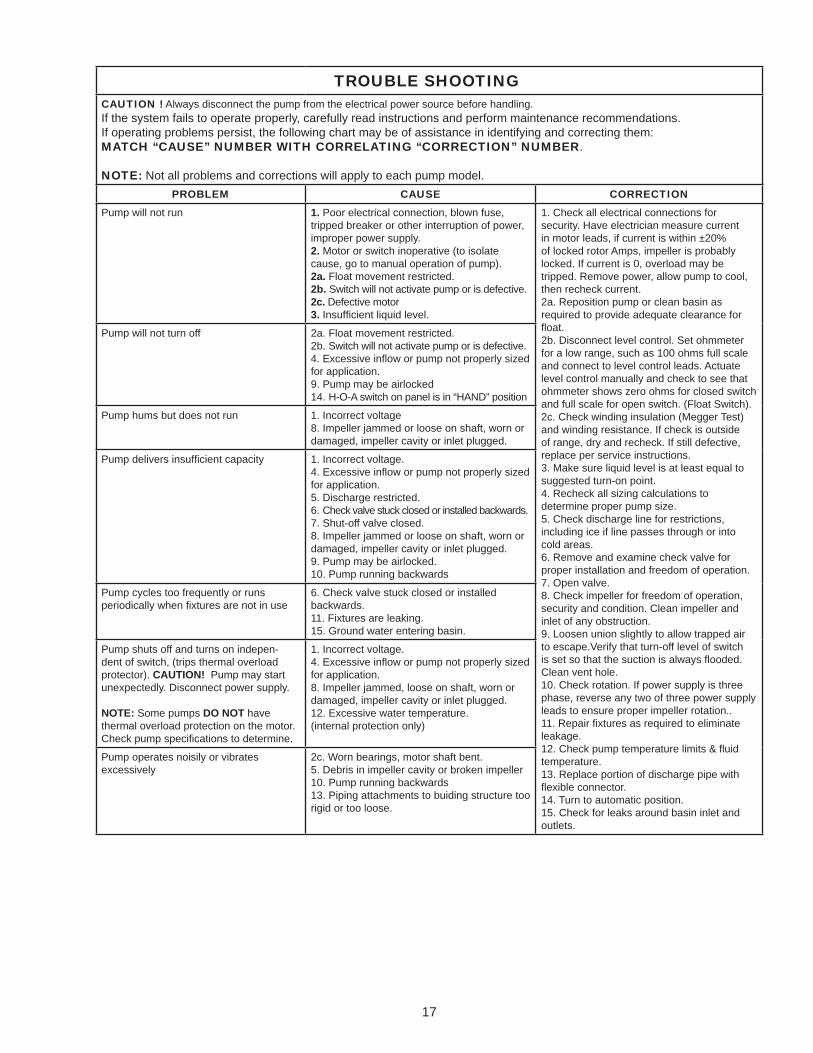
TROUBLE SHOOTINGCAUTION ! Always disconnect the pump from the electrical power source before handling.If the system fails to operate properly, carefully read instructions and perform maintenance recommendations.If operating problems persist, the following chart may be of assistance in identifying and correcting them:MATCH “CAUSE” NUMBER WITH CORRELATING “CORRECTION” NUMBER.
NOTE: Not all problems and corrections will apply to each pump model.PROBLEM CAUSE CORRECTION
Pump will not run 1. Poor electrical connection, blown fuse, tripped breaker or other interruption of power, improper power supply.2. Motor or switch inoperative (to isolate cause, go to manual operation of pump).2a. Float movement restricted.2b. Switch will not activate pump or is defective.2c. Defective motor3. Insuffi cient liquid level.
1. Check all electrical connections for security. Have electrician measure current in motor leads, if current is within ±20% of locked rotor Amps, impeller is probably locked. If current is 0, overload may be tripped. Remove power, allow pump to cool, then recheck current.2a. Reposition pump or clean basin as required to provide adequate clearance for fl oat.2b. Disconnect level control. Set ohmmeter for a low range, such as 100 ohms full scale and connect to level control leads. Actuate level control manually and check to see that ohmmeter shows zero ohms for closed switch and full scale for open switch. (Float Switch).2c. Check winding insulation (Megger Test) and winding resistance. If check is outside of range, dry and recheck. If still defective, replace per service instructions.3. Make sure liquid level is at least equal to suggested turn-on point.4. Recheck all sizing calculations to determine proper pump size.5. Check discharge line for restrictions, including ice if line passes through or into cold areas.6. Remove and examine check valve for proper installation and freedom of operation.7. Open valve.8. Check impeller for freedom of operation, security and condition. Clean impeller and inlet of any obstruction.9. Loosen union slightly to allow trapped air to escape.Verify that turn-off level of switch is set so that the suction is always fl ooded. Clean vent hole.10. Check rotation. If power supply is three phase, reverse any two of three power supply leads to ensure proper impeller rotation..11. Repair fi xtures as required to eliminate leakage.12. Check pump temperature limits & fl uid temperature.13. Replace portion of discharge pipe with fl exible connector.14. Turn to automatic position.15. Check for leaks around basin inlet and outlets.
Pump will not turn off 2a. Float movement restricted.2b. Switch will not activate pump or is defective.4. Excessive infl ow or pump not properly sized for application.9. Pump may be airlocked14. H-O-A switch on panel is in “HAND” position
Pump hums but does not run 1. Incorrect voltage8. Impeller jammed or loose on shaft, worn or damaged, impeller cavity or inlet plugged.
Pump delivers insuffi cient capacity 1. Incorrect voltage.4. Excessive infl ow or pump not properly sized for application.5. Discharge restricted.6. Check valve stuck closed or installed backwards.7. Shut-off valve closed.8. Impeller jammed or loose on shaft, worn or damaged, impeller cavity or inlet plugged.9. Pump may be airlocked.10. Pump running backwards
Pump cycles too frequently or runs periodically when fi xtures are not in use
6. Check valve stuck closed or installed backwards.11. Fixtures are leaking.15. Ground water entering basin.
Pump shuts off and turns on indepen-dent of switch, (trips thermal overload protector). CAUTION! Pump may start unexpectedly. Disconnect power supply.
NOTE: Some pumps DO NOT have thermal overload protection on the motor. Check pump specifi cations to determine.
1. Incorrect voltage.4. Excessive infl ow or pump not properly sized for application.8. Impeller jammed, loose on shaft, worn or damaged, impeller cavity or inlet plugged.12. Excessive water temperature. (internal protection only)
Pump operates noisily or vibrates excessively
2c. Worn bearings, motor shaft bent.5. Debris in impeller cavity or broken impeller10. Pump running backwards13. Piping attachments to buiding structure too rigid or too loose.
18
FIGURE 13

19
FIGURE 14
20
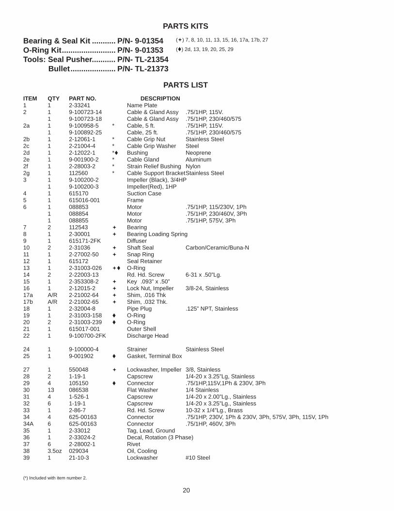
PARTS KITS
Bearing & Seal Kit ........... P/N- 9-01354O-Ring Kit ......................... P/N- 9-01353Tools: Seal Pusher........... P/N- TL-21354 Bullet ..................... P/N- TL-21373
PARTS LISTITEM QTY PART NO. DESCRIPTION 1 1 2-33241 Name Plate 2 1 9-100723-14 Cable & Gland Assy .75/1HP, 115V. 1 9-100723-18 Cable & Gland Assy .75/1HP, 230/460/575 2a 1 9-100958-5 * Cable, 5 ft. .75/1HP, 115V. 1 9-100892-25 Cable, 25 ft. .75/1HP, 230/460/575 2b 1 2-12061-1 * Cable Grip Nut Stainless Steel 2c 1 2-21004-4 * Cable Grip Washer Steel 2d 1 2-12022-1 * Bushing Neoprene 2e 1 9-001900-2 * Cable Gland Aluminum 2f 1 2-28003-2 * Strain Relief Bushing Nylon 2g 1 112560 * Cable Support Bracket Stainless Steel 3 1 9-100200-2 Impeller (Black), 3/4HP 1 9-100200-3 Impeller(Red), 1HP 4 1 615170 Suction Case 5 1 615016-001 Frame 6 1 088853 Motor .75/1HP, 115/230V, 1Ph 1 088854 Motor .75/1HP, 230/460V, 3Ph 1 088855 Motor .75/1HP, 575V, 3Ph 7 2 112543 Bearing 8 1 2-30001 Bearing Loading Spring 9 1 615171-2FK Diffuser 10 2 2-31036 Shaft Seal Carbon/Ceramic/Buna-N 11 1 2-27002-50 Snap Ring 12 1 615172 Seal Retainer 13 1 2-31003-026 O-Ring 14 2 2-22003-13 Rd. Hd. Screw 6-31 x .50”Lg. 15 1 2-353308-2 Key .093” x .50” 16 1 2-12015-2 Lock Nut, Impeller 3/8-24, Stainless 17a A/R 2-21002-64 Shim, .016 Thk 17b A/R 2-21002-65 Shim, .032 Thk. 18 1 2-32004-8 Pipe Plug .125” NPT, Stainless 19 1 2-31003-158 O-Ring 20 2 2-31003-239 O-Ring 21 1 615017-001 Outer Shell 22 1 9-100700-2FK Discharge Head
24 1 9-100000-4 Strainer Stainless Steel 25 1 9-001902 Gasket, Terminal Box
27 1 550048 Lockwasher, Impeller 3/8, Stainless 28 2 1-19-1 Capscrew 1/4-20 x 3.25”Lg, Stainless 29 4 105150 Connector .75/1HP,115V,1Ph & 230V, 3Ph 30 13 086538 Flat Washer 1/4 Stainless 31 4 1-526-1 Capscrew 1/4-20 x 2.00”Lg., Stainless 32 6 1-19-1 Capscrew 1/4-20 x 3.25”Lg., Stainless 33 1 2-86-7 Rd. Hd. Screw 10-32 x 1/4”Lg., Brass 34 4 625-00163 Connector .75/1HP, 230V, 1Ph & 230V, 3Ph, 575V, 3Ph, 115V, 1Ph34A 6 625-00163 Connector .75/1HP, 460V, 3Ph35 1 2-33012 Tag, Lead, Ground 36 1 2-33024-2 Decal, Rotation (3 Phase) 37 6 2-28002-1 Rivet 38 3.5oz 029034 Oil, Cooling 39 1 21-10-3 Lockwasher #10 Steel
(*) Included with item number 2.
() 7, 8, 10, 11, 13, 15, 16, 17a, 17b, 27
() 2d, 13, 19, 20, 25, 29

21
FIGURE 15
PARTS LISTP/N: 9-101811-02, NEMA 4, .75HP, 1Ph, 115V.P/N: 9-101812-02, NEMA 4, .75HP, 1Ph, 230V.
ITEM QTY. PART NO. DESCRIPTION 80. 1 9-100853 Enclosure, NEMA 4, 1 Phase 81 2 2-22009-10 Screw 6-32 x .50”Lg. 82 2 2-12017-2 Connector .50” 83 1 2-31023 Seal (Toggle Switch) 84 1 2-13024 Toggle Switch 85 1 2-13026 Fuse Holder 86 1 2-33256 Connection Diagram 115V., 1 Phase 1 2-33259 Connection Diagram 230V., 1 Phase 87 5 2-22009-16 Screw 8-32 x .50”Lg 88 1 9-975938-13-07 Wire (Not Shown) 14GA., Orange, 7”Lg 89 2 9-975938-5-04 Wire (Not Shown) 14GA., Red, 4”Lg. 90 1 9-975938-22-06 Wire (Not Shown) 14GA., Black, 6”Lg. 91 1 035864 Capacitor, Run 370V, 35MFD 92 1 2-12019-5 Clamp, Capacitor 93 2 2-12055-1 Connector Nut .50 94 2 2-12026-2 Wire Connector (Not Shown) 600V, .53” x .937” 95 1 2-12026-3 Wire Connector (Not Shown) 600V, .43 x .843” 96 1 9-100803 Handle 97 1 9-100993-6 Cable, 6Ft. 115V. 1 9-100995-6 Cable, 6Ft. 230V. 98 1 2-13010-17 Capacitor, Start 250V, 64MFD 99 1 2-12019 Clamp 100 1 9-975938-10-05 Wire Assembly (Not Shown) 14GA., Black, 5”Lg. 101 1 9-975938-10-04 Wire Assembly (Not Shown) 14GA., Black, 4”Lg. 102 1 2-21001-15 Lockwasher, Ground #8 103 1 2-13042-120 Fuse, 115V BUSS, 250V, 12Amp 1 2-13042-070 Fuse, 230V. BUSS, 250V, 7Amp 104 1 112239 Wire Assembly 14GA. Green, 11” Lg 105 1 625-02641-001 Relay 115V. 1 625-02650-001 Relay 230V. 106 2 2-21001-20 Lockwasher #10 107 2 625-00320 Clamp, Cable 108 1 2-12012-1 Terminal, Disconnect (Not Shown) 109 1 15-4-1 Hex Nut 10-32, Stainless 110 1 112553 Clamp, Fuse, Holder
22
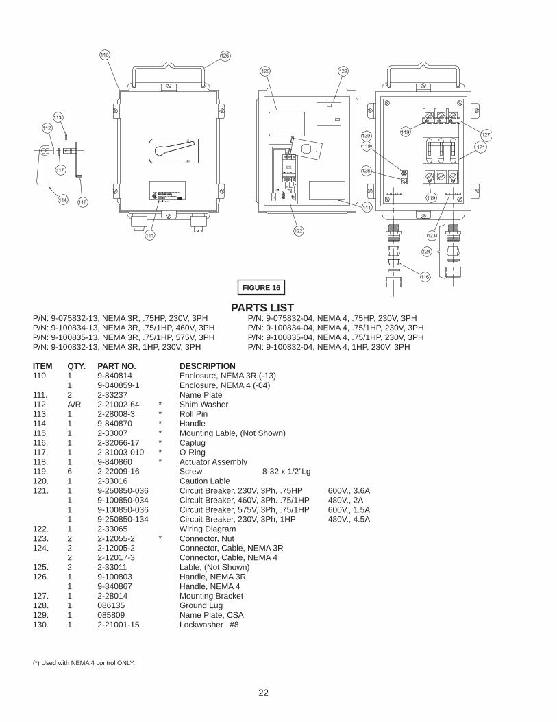
FIGURE 16
PARTS LISTP/N: 9-075832-13, NEMA 3R, .75HP, 230V, 3PH P/N: 9-075832-04, NEMA 4, .75HP, 230V, 3PH P/N: 9-100834-13, NEMA 3R, .75/1HP, 460V, 3PH P/N: 9-100834-04, NEMA 4, .75/1HP, 230V, 3PHP/N: 9-100835-13, NEMA 3R, .75/1HP, 575V, 3PH P/N: 9-100835-04, NEMA 4, .75/1HP, 230V, 3PHP/N: 9-100832-13, NEMA 3R, 1HP, 230V, 3PH P/N: 9-100832-04, NEMA 4, 1HP, 230V, 3PH ITEM QTY. PART NO. DESCRIPTION 110. 1 9-840814 Enclosure, NEMA 3R (-13) 1 9-840859-1 Enclosure, NEMA 4 (-04) 111. 2 2-33237 Name Plate 112. A/R 2-21002-64 * Shim Washer 113. 1 2-28008-3 * Roll Pin 114. 1 9-840870 * Handle 115. 1 2-33007 * Mounting Lable, (Not Shown) 116. 1 2-32066-17 * Caplug 117. 1 2-31003-010 * O-Ring 118. 1 9-840860 * Actuator Assembly 119. 6 2-22009-16 Screw 8-32 x 1/2”Lg 120. 1 2-33016 Caution Lable 121. 1 9-250850-036 Circuit Breaker, 230V, 3Ph, .75HP 600V., 3.6A 1 9-100850-034 Circuit Breaker, 460V, 3Ph. .75/1HP 480V., 2A 1 9-100850-036 Circuit Breaker, 575V, 3Ph, .75/1HP 600V., 1.5A 1 9-250850-134 Circuit Breaker, 230V, 3Ph, 1HP 480V., 4.5A 122. 1 2-33065 Wiring Diagram 123. 2 2-12055-2 * Connector, Nut 124. 2 2-12005-2 Connector, Cable, NEMA 3R 2 2-12017-3 Connector, Cable, NEMA 4 125. 2 2-33011 Lable, (Not Shown) 126. 1 9-100803 Handle, NEMA 3R 1 9-840867 Handle, NEMA 4 127. 1 2-28014 Mounting Bracket 128. 1 086135 Ground Lug 129. 1 085809 Name Plate, CSA 130. 1 2-21001-15 Lockwasher #8
(*) Used with NEMA 4 control ONLY.
23
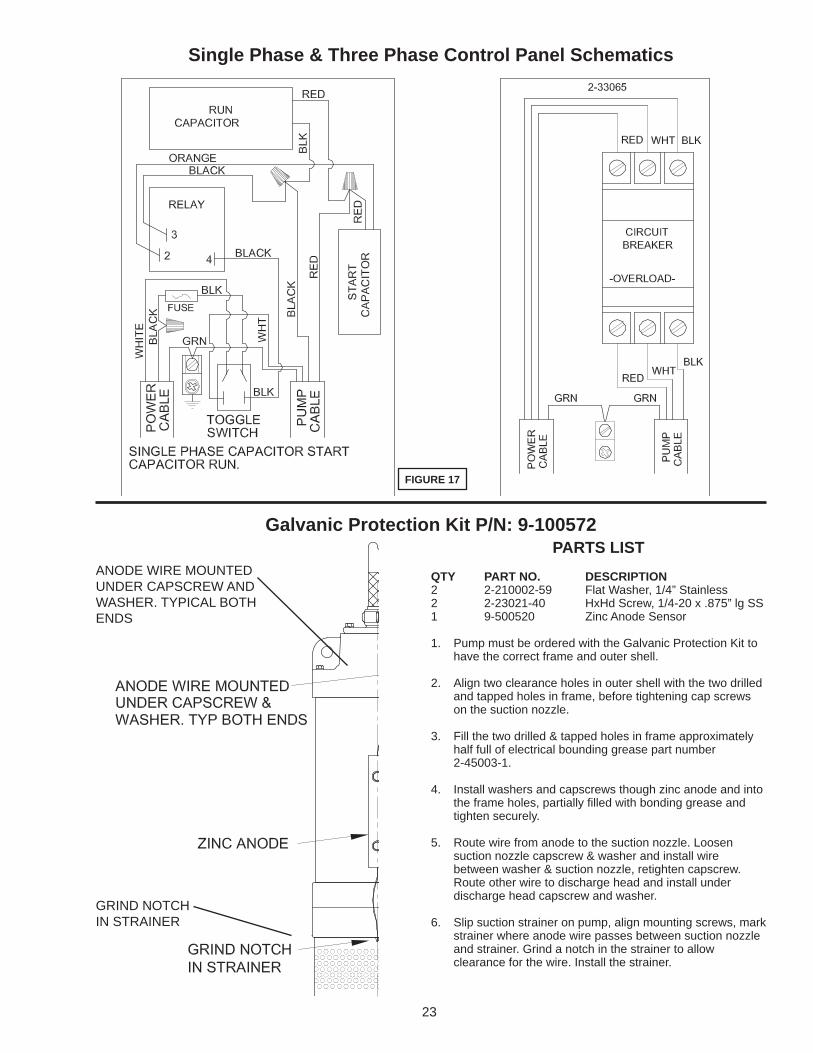
Single Phase & Three Phase Control Panel Schematics
FIGURE 17
PARTS LISTQTY PART NO. DESCRIPTION2 2-210002-59 Flat Washer, 1/4” Stainless2 2-23021-40 HxHd Screw, 1/4-20 x .875” lg SS1 9-500520 Zinc Anode Sensor
1. Pump must be ordered with the Galvanic Protection Kit to have the correct frame and outer shell.
2. Align two clearance holes in outer shell with the two drilled and tapped holes in frame, before tightening cap screws on the suction nozzle.
3. Fill the two drilled & tapped holes in frame approximately half full of electrical bounding grease part number 2-45003-1.
4. Install washers and capscrews though zinc anode and into the frame holes, partially fi lled with bonding grease and tighten securely.
5. Route wire from anode to the suction nozzle. Loosen suction nozzle capscrew & washer and install wire between washer & suction nozzle, retighten capscrew. Route other wire to discharge head and install under discharge head capscrew and washer.
6. Slip suction strainer on pump, align mounting screws, mark strainer where anode wire passes between suction nozzle and strainer. Grind a notch in the strainer to allow clearance for the wire. Install the strainer.
Galvanic Protection Kit P/N: 9-100572
GRIND NOTCH IN STRAINER
ANODE WIRE MOUNTED UNDER CAPSCREW AND WASHER. TYPICAL BOTH ENDS
24
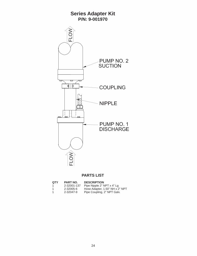
Series Adapter KitP/N: 9-001970
PARTS LISTQTY PART NO. DESCRIPTION1 2-32001-137 Pipe Nipple 2” NPT x 4” Lg1 2-32005-6 Hose Adapter, 1.50” NH x 2” NPT1 2-32047-9 Pipe Coupling, 2” NPT Galv.

25

26
RETURNED GOODSRETURN OF MERCHANDISE REQUIRES A “RETURNED GOODS AUTHORIZATION”.
CONTACT YOUR LOCAL CRANE PUMPS & SYSTEMS, INC. DISTRIBUTOR.
Products Returned Must Be Cleaned, Sanitized, Or Decontaminated As Necessary Prior To Shipment, To Insure That Employees Will Not Be Exposed To Health Hazards In Handling Said Material. All Applicable Laws And Regulations Shall Apply.
IMPORTANT!WARRANTY REGISTRATION
Your product is covered by the enclosed Warranty.To complete the Warranty Registration Form go to:
http://www.cranepumps.com/ProductRegistration/
If you have a claim under the provision of the warranty, contact your local Crane Pumps & Systems, Inc. Distributor.