08 rn30036 en06gln0_rnc_parameters
113
Soc Classification level Presentation / Author / Date 1 © Nokia Siemens Networks Module 6 RNC transmission detailed planning parameters
-
Upload
mahram2008 -
Category
Technology
-
view
45 -
download
0
Transcript of 08 rn30036 en06gln0_rnc_parameters

Soc Classification level Presentation / Author / Date1 © Nokia Siemens Networks
Module 6RNC transmission detailed planning parameters

3GTPL – Session 7 – RNC Detailed Parameter Planning – JKl – 05.12.20082 © Nokia Siemens Networks
Three Ways To Configure The RNC1. MML (Man Machine Language) commands:
– These are 4-letter-commands, starting with Z, e. g. ZABC.– Nearly every transmission related setting is configurable via MML command.– May be automated by batch-files.– CoCo objects cannot be created with MML commands
2. RNW (Radio NetWork) Object Browser GUI (Graphical User Interface):– Graphical software application stored in the NEMU of the RNC, downloaded
and started via Application Launcher.– Used to create all radio configuration related parameters (no in this session)– Also used to create CoCo related parameters for Iub (shown later).– Automatically configures a lot of parameters by using templates and rules.
3. RAML1.0 XML files:– Coming from NetAct Plan Editor, downloaded to NetAct Radio Access
Configurator in OSS, from there downloaded to RNC.– Contains mainly radio configuration related parameters for each NodeB.– CoCo creation via RAML1.0 XML files.
3GTPL – Session 7 – RNC Detailed Parameter Planning – JKl – 05.12.20083 © Nokia Siemens Networks
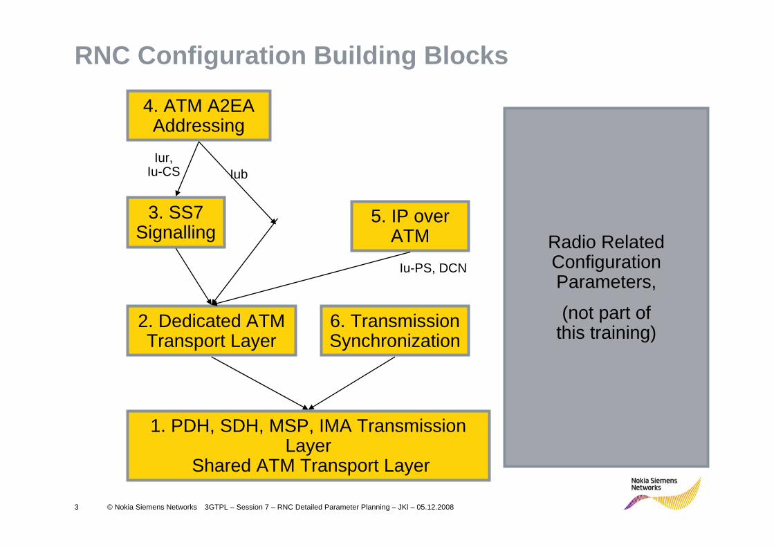
RNC Configuration Building Blocks
1. PDH, SDH, MSP, IMA Transmission Layer
Shared ATM Transport Layer
2. Dedicated ATM Transport Layer
6. Transmission Synchronization
3. SS7 Signalling
5. IP over ATM
4. ATM A2EA Addressing
Radio Related Configuration Parameters,
(not part ofthis training)
Iur,Iu-CS Iub
Iu-PS, DCN

3GTPL – Session 7 – RNC Detailed Parameter Planning – JKl – 05.12.20084 © Nokia Siemens Networks
RN
C C
onfiguration detailed Workflow
StartStop
CoC
oparam
eter is the m
odified param
eter based on Link
Termination
Point, Routing
Objects and D
igit A
nalysis, etc
Configure C
oCo
Create physical interface and shared A
TM ressource
PDH
interfaceSD
H interface
PET
IMA
Group
Physical Trail Termination Point –
PhyTTP
Protection Group
SETATM
Interface, Access Profile
VP/VC Link Term
ination Point
Create dedicated A
TM resource
Create SS7 signalling
MTP3
SCC
P
ATM
Route
End Point Group
End Point Parameters
Digit A
nalysis
Routing
objects and digit analysisC
reate IP over ATM
forD
CN
and Iu-PS
IPoATM
I/F
IP Addressing
Static Route
for:Iub, Iur,
IuCS, IuPS, M
TP3 (A
AL2sig/R
NSA
P/RA
NA
P), DC
N
IPoATM
for:Iubfor:IuPS, D
CN
IPoA
TM
for:Iur, IuC
S, IuPS, M
TP3 (A
AL2sig/
RN
SAP/
RA
NA
P)
for:D
CN
IPoA
TM
IuPS
for:all but Iub
for:Iur,
IuCS

3GTPL – Session 7 – RNC Detailed Parameter Planning – JKl – 05.12.20085 © Nokia Siemens Networks
RNC general parameters
These parameters identifies a specific RNC among other network elements as in the example below
4535866323232AESA Address (remote node - MGW for Iu-CS)
4535866121212AESA Address (local node - RNC)358661122334GT Number (local node - RNC)*
RN01CSPN (Signalling Point Name - local node)8340SPC (Signalling Point Code - local node)222Mobile Country Code - MCC01Mobile Network Code (MNC)
2Mobile Network Code (MNC Default Length)
City CentreRNC LocationRNC01CCRNC Name
16RNC ID
(*) the global title is not always used from signalling.

3GTPL – Session 7 – RNC Detailed Parameter Planning – JKl – 05.12.20086 © Nokia Siemens Networks
Introduction to Topology for Configuration and Parameterization Example
RNC type7
MSSMGW
SGSN
ATM-cloud
RNC01
RNC11
RNC07
RNC09
RNC14
Iu-PS on SDH with16xUP & 4xSig
Iu-CS on SDH with20xUP & 8x Sig MGW
Sigonly
3xIur on SDH with2(3) UP&1 Sig each
2x Iuron IMA

3GTPL – Session 7 – RNC Detailed Parameter Planning – JKl – 05.12.20087 © Nokia Siemens Networks
Brief introduction to MML-commands• The first time in touch with MML-Syntax might cause some confusion.
– The first letter is always a „Z“, this is needed for the system to start from the top of the command hierarchy.
– The next two letters determine the command family– The last letter is the command itself. Not always but often this letter shows what
command is behind, e.g. „C“ for Create, „M“ for Modify, „I“ for Interrogate, „D“ for Delete.• Considering e.g. TRS issues, the planner fills the RNC data built with all relevant
input. There are mandatory and optional tables, depending on needed technologies and features.
• As this data built contains also a lot of SS7, ATM-routing & IP topics, often other planners of different fields must get involved
• When data built is complete the integration engineer receives the tables and creates command strings
• Usually small changes or some parameter adaptations in the RNC configuration are directly entered in the system via MML-commands.
• In case of major changes or a complete new configuration respectively set up of an RNC it works different
• Integration / Commissioning engineers produce all command strings and import them e.g. with the HIT-macro.

3GTPL – Session 7 – RNC Detailed Parameter Planning – JKl – 05.12.20088 © Nokia Siemens Networks
MML-Commands and their structure
• An MML command can contain just one item (e.g. interrogate), but it possibly consist of 25-30 parameter settings.
• Each parameter is separated by a comma “ , “ from the next one• These parameters are then combined into groups, separated by a colon “ : “ from
each other. E.g: ZLAC:A,B,C,D:• There might be groups were many parameters are given, but only one/some input
is required or the provided default is suitable. In this case the input is skipped with the comma. Even a whole command group could remain empty and is just terminated with a colon. Here are some examples based on ZLAC:A,B,C,D:
• A=1, B=2, C=N/A, D=YES =>ZLAC:1,2,,YES;• A=1, B=N/A, C&D=Default =>ZLAC:1;• A&B&C=Default, D=YES =>ZLAC:,,,YES:;• All values Default or N/A =>ZLAC:;
• Each command starts with a „Z“ and ends with a semicolon “ ; “• Example: ZOBC:A,B,C,D:F,G:J;
• On the next slide there‘s an example how to create a MML-command string with given input, based on the command syntax.

3GTPL – Session 7 – RNC Detailed Parameter Planning – JKl – 05.12.20089 © Nokia Siemens Networks
Example: Creating & Activating 2 SDH InterfacesSyntax:YAN: <SDH exchange terminal index>..., [<higher order path number> | <higher order path number>, <lower order path number>]: [<SES BIP threshold>]: [<SD BER threshold>]: [<SF BER threshold>]: [DIA = (ON | OFF) | LINE = (ON | OFF) | LASER = (ON | OFF)]...: [VC3 | VC4 | VC3VC11 | VC3VC12 | VC4VC11 | VC4VC12]: [SDH | ATMML | SONET]: [ASYNCH | BITSYNCH | BYTESYNCH];
Parameter Input:SDH exchange terminal index: 0 and 4 => 0&4higher order path number: N/A for VC4 => lower order path number: N/A for VC4 => :SES BIP threshold: 2400 (Default set by system) => :SD BER threshold: 5 (Default set by system) => :SF BER threshold: 5 (Default set by system) => :diagnostic loopback status: N/A for tests only =>line loopback status: N/A for tests only => :laser status: ON => LASER=ON:VC mapping: VC4 => VC4:SDH protocol: SDH => SDH:lower order path mapping mode: N/A for VC4 =>
=> ; to execute command
Final MML command: ZYAN:0&4::::LASER=ON:VC4:SDH;

3GTPL – Session 7 – RNC Detailed Parameter Planning – JKl – 05.12.200810 © Nokia Siemens Networks
2nd Example: LCC – Create ATM-VC Termination PointSyntax Comments MML-fragment
LCC: <interface id>, (VP | VC), [<VPI>], [<VCI>], => We assume IF=12 / VPI=4 / VCI=40[<VPL service level>]: => The Service Level is VC =>string is:“12,4,40,VC:”
[[INSEG | SEGEND | NO] | NO def], => We use default, so no entry[[FULL | NO] | NO def]: => We use default, so no entry => string is: “:”
<ingress service category>, [E | D] | D def], => C for CBR, and Shaping disabled[[E | D] | D def],[<ingress QoS class>]: => EPD/PPD disabled, and QoS=C1 => string is: “C,,,C1:”
<egress service category>, [E | D] | D def],[[E | D] | D def],[<egress QoS class>]: => same story for Egress direction => string is: “C,,,C1”
[<ingress CDVT_PCR>, <ingress CDVT_PCR unit>], => We assume CDVT= 1msec[<ingress CDVT_SCR>, <ingress CDVT_SCR unit>],[<egress CDVT_PCR>, <egress CDVT_PCR unit>], => same for other direction =>string is“1,MSEC,,,1MSEC:”[<egress CDVT_SCR>, <egress CDVT_SCR unit>]:
[<ingress PCR>], [<ingress PCR unit>], => We assume PCR= 1000 cps => string is: “1,KCPS:”[<ingress SCR>], [<ingress SCR unit>],[<ingress Burst_Tol>], [<ingress Burst_Tol unit>]:
[<egress PCR>], [<egress PCR unit>], => same for other direction => string is: “1,KCPS:”[<egress SCR>], [<egress SCR unit>],[<egress Burst_Tol>], [<egress Burst_Tol unit>]:
[[[STATE = LOCKED | UNLOCKED] | UNLOCKED def] | => VC should be active [MAXVCI = <max VCI bit>]]... ; => ignore and finalize command => string is: “;”
Final command: ZLCC:12,4,40,VC::C,,,C1,,,C1:1,MSEC,,,1,MSEC:1,KCPS:1KCPS;
3GTPL – Session 7 – RNC Detailed Parameter Planning – JKl – 05.12.200811 © Nokia Siemens Networks
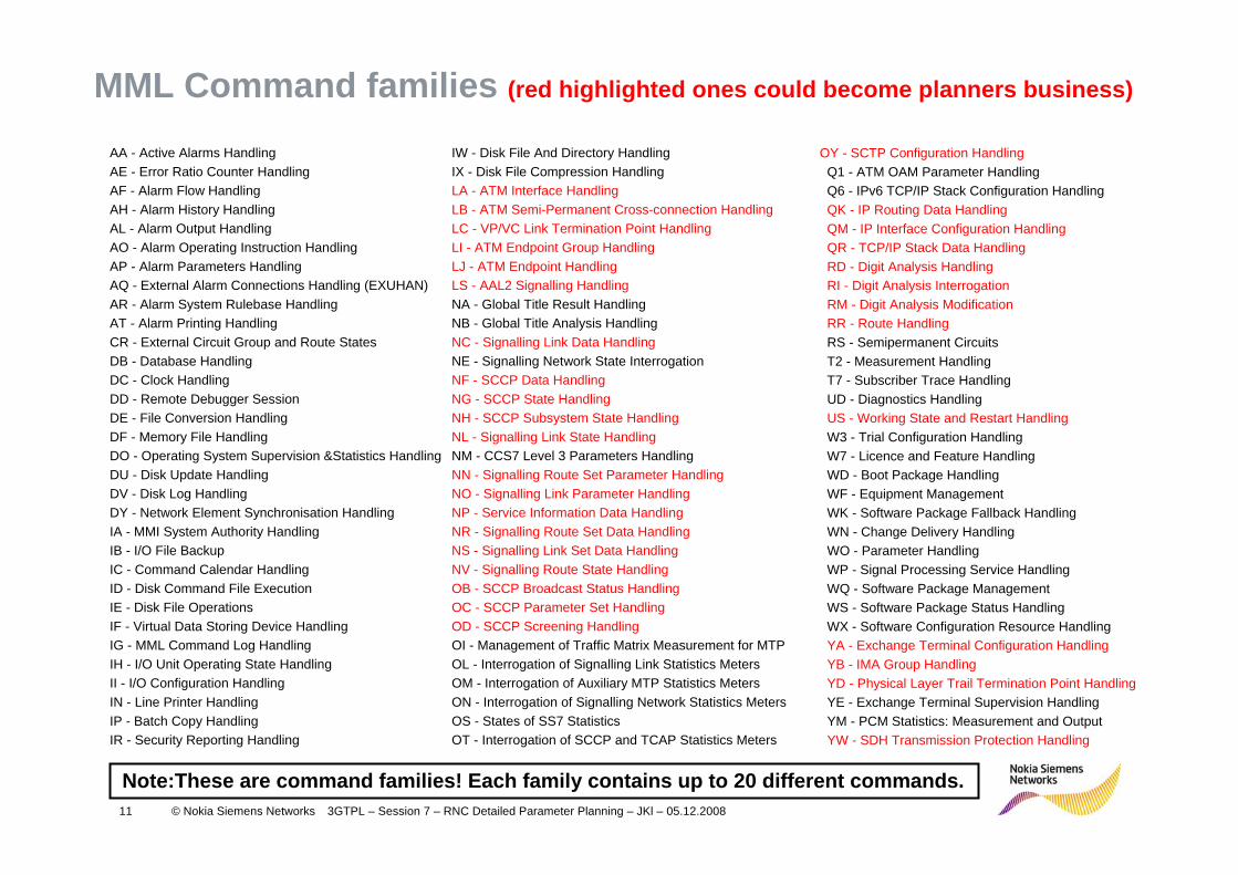
MML Command families (red highlighted ones could become planners business)
AA - Active Alarms Handling AE - Error Ratio Counter Handling AF - Alarm Flow Handling AH - Alarm History Handling AL - Alarm Output Handling AO - Alarm Operating Instruction Handling AP - Alarm Parameters Handling AQ - External Alarm Connections Handling (EXUHAN) AR - Alarm System Rulebase Handling AT - Alarm Printing Handling CR - External Circuit Group and Route States DB - Database Handling DC - Clock Handling DD - Remote Debugger Session DE - File Conversion Handling DF - Memory File Handling DO - Operating System Supervision &Statistics Handling DU - Disk Update Handling DV - Disk Log Handling DY - Network Element Synchronisation Handling IA - MMI System Authority Handling IB - I/O File Backup IC - Command Calendar Handling ID - Disk Command File Execution IE - Disk File Operations IF - Virtual Data Storing Device Handling IG - MML Command Log Handling IH - I/O Unit Operating State Handling II - I/O Configuration Handling IN - Line Printer Handling IP - Batch Copy Handling IR - Security Reporting Handling
IW - Disk File And Directory Handling IX - Disk File Compression Handling LA - ATM Interface Handling LB - ATM Semi-Permanent Cross-connection Handling LC - VP/VC Link Termination Point Handling LI - ATM Endpoint Group Handling LJ - ATM Endpoint Handling LS - AAL2 Signalling HandlingNA - Global Title Result Handling NB - Global Title Analysis Handling NC - Signalling Link Data Handling NE - Signalling Network State Interrogation NF - SCCP Data Handling NG - SCCP State Handling NH - SCCP Subsystem State Handling NL - Signalling Link State Handling NM - CCS7 Level 3 Parameters Handling NN - Signalling Route Set Parameter Handling NO - Signalling Link Parameter Handling NP - Service Information Data Handling NR - Signalling Route Set Data Handling NS - Signalling Link Set Data Handling NV - Signalling Route State Handling OB - SCCP Broadcast Status Handling OC - SCCP Parameter Set Handling OD - SCCP Screening Handling OI - Management of Traffic Matrix Measurement for MTP OL - Interrogation of Signalling Link Statistics Meters OM - Interrogation of Auxiliary MTP Statistics Meters ON - Interrogation of Signalling Network Statistics Meters OS - States of SS7 Statistics OT - Interrogation of SCCP and TCAP Statistics Meters
OY - SCTP Configuration HandlingQ1 - ATM OAM Parameter Handling Q6 - IPv6 TCP/IP Stack Configuration Handling QK - IP Routing Data Handling QM - IP Interface Configuration Handling QR - TCP/IP Stack Data Handling RD - Digit Analysis Handling RI - Digit Analysis Interrogation RM - Digit Analysis Modification RR - Route Handling RS - Semipermanent Circuits T2 - Measurement Handling T7 - Subscriber Trace Handling UD - Diagnostics Handling US - Working State and Restart Handling W3 - Trial Configuration Handling W7 - Licence and Feature Handling WD - Boot Package Handling WF - Equipment Management WK - Software Package Fallback Handling WN - Change Delivery Handling WO - Parameter Handling WP - Signal Processing Service Handling WQ - Software Package Management WS - Software Package Status Handling WX - Software Configuration Resource Handling YA - Exchange Terminal Configuration Handling YB - IMA Group Handling YD - Physical Layer Trail Termination Point HandlingYE - Exchange Terminal Supervision Handling YM - PCM Statistics: Measurement and Output YW - SDH Transmission Protection Handling
Note:These are command families! Each family contains up to 20 different commands.

3GTPL – Session 7 – RNC Detailed Parameter Planning – JKl – 05.12.200812 © Nokia Siemens Networks
Iub/RNC
Iur
Iu-CS
Iu-PS
Iu-BC
Configuring physical interface parameters
Iub/AXCPhysical Interfaces
PDH/IMA/SDHSynchronization ATM resources
Cross connections
IPoAM
Physical Interfaces
PDH/IMA/SDHPhyTTP ATM resources
ConnectionConfiguration
(COCO)IPoAM
Physical Interfaces
PDH/IMA/SDHPhyTTP
ATM resourcesVPltp/VCltp SS7 Signaling
Routing and Digit Analysis
Physical Interfaces
PDH/IMA/SDHPhyTTP
ATM resourcesVPltp/VCltp SS7 Signaling
Iu-CSParameters
In RNC
Routing and Digit Analysis
Physical Interfaces
PDH/IMA/SDHPhyTTP
ATM resourcesVPltp/VCltp SS7 Signaling
Iu-PSParameters
In RNCIPoAUD
Physical Interfaces
PDH/IMA/SDHPhyTTP
ATM resourcesVPltp/VCltp
Iu-BCParameters in
RNCIPoAUD
3GTPL – Session 7 – RNC Detailed Parameter Planning – JKl – 05.12.200813 © Nokia Siemens Networks
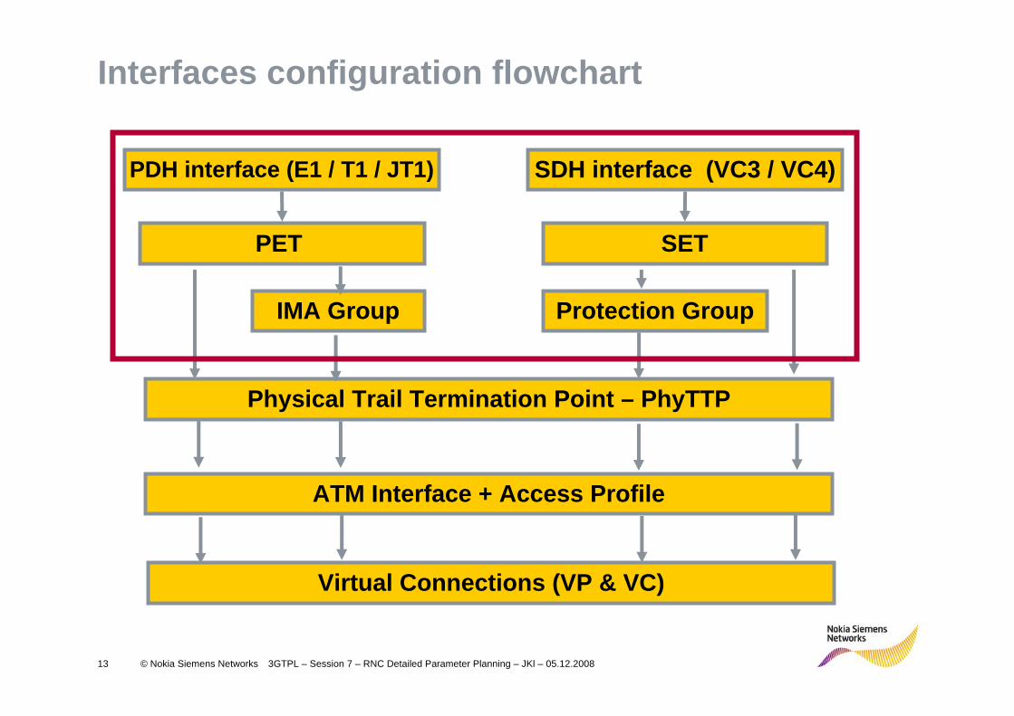
Interfaces configuration flowchart
PDH interface (E1 / T1 / JT1) SDH interface (VC3 / VC4)
PET
IMA Group
Physical Trail Termination Point – PhyTTP
Protection Group
SET
ATM Interface + Access Profile
Virtual Connections (VP & VC)

3GTPL – Session 7 – RNC Detailed Parameter Planning – JKl – 05.12.200814 © Nokia Siemens Networks
Configuring PDH for ATM transport
The following points should be covered when planning the physical interfaces• Parameters for PDH physical interfaces • Parameters for IMA group definition in the RNC• Parameters for SDH physical interface in the RNC• Parameters for SDH protection group in the RNC• Parameters for the Physical Trail Termination Point (PhyTTP)

3GTPL – Session 7 – RNC Detailed Parameter Planning – JKl – 05.12.200815 © Nokia Siemens Networks
Required planning parameters for PDH interface in the RNC
(1): Double Frame Mode(2): If Fractional E1 is used, it should be indicated what are the used time slots,
and if TS-16 is used or not.
Note that RNC450 and RNC196upg can house only one NIP interface card.
1 to 31in case of Fractional E1 (2)YAWPET Time slot usage4 to 8SA bit for SSMON, OFFLine LoopbackON, OFFDiagnostic LoopbackON, OFFPayload scramblingYAMPET configurationCRC 4, DBLF (1)Frame alignment modeNORMFunctional modeYECE1 functional mode75 W, 120 WImpedanceE1, T1, JT1Interface operation mode0-191Network interface unit indexNIP1Network interface unit typeYAENIP1 operation modePossible valuesParameterMMLTask

3GTPL – Session 7 – RNC Detailed Parameter Planning – JKl – 05.12.200816 © Nokia Siemens Networks
Required planning parameters for IMA group in the RNC
(1): All PET should belong to the same NIP unit. They do not have to be consecutive. There can be up to 8xE1 in an IMA group.(2): The minimum number of links defines number of links we allow IMA engine to serve if other links are down from the group.
1-8Minimum number of links(2)
0-191PET index(1)
1-224IMA group id YBCIMA group
Possible valuesParameterMMLTask

3GTPL – Session 7 – RNC Detailed Parameter Planning – JKl – 05.12.200817 © Nokia Siemens Networks
The RNC Data built• Data built is used when new RNC is planned• Data built is used to carry out major changes in an existing RNC• Data built consist of an Excel-file with 50 sheets (tables) for
– PDH Physical Layer Parameters– SDH Physical Layer Parameters– ATM Parameters– SS7 Parameter– Digit Analysis Parameters– IP Parameters– Synchronization Parameter– Other Parameters
• Planning engineers are filling tables with all needed input• Integration engineers use these tables to enter commands into RNC• Each sheet is in the order as integration commands are executed• Each table is built up in the order of parameters for MML command• Accordant MML-command(s) are always within table• Often databuilt is used to display CoCo objects, even though they‘re not
entered with MML commands

3GTPL – Session 7 – RNC Detailed Parameter Planning – JKl – 05.12.200818 © Nokia Siemens Networks
PDH-Interface Configuration – Data built overviewPDH Network Interface Commands: YAE
ParametersNetwork Interface
Unit typeNetwork interface
unit IndexInterface
operation modeImpedence
Data format MNEMONIC NUMERIC MNEMONIC NUMERIC
Value RangeNIP1/ NIWU / IWS1T
0 ... 11, limited by RNC units
E1, JT1, T175, 120 Only E1
Units OhmNIP1 1 E1 75
ETSI Functional Mode Parameter Commands: YEC
Parameters Unit Type Unit IndexFrame Alignment
mode REMARKS
Data format MNEMONIC NUMERIC MNEMONIC INFO
Value RangePET
0 ... 191,DBLF, CRC4
PET 0 CRC4 Iur to RNC BLN01PET 1 CRC4 Iur to RNC BLN01PET 2 CRC4 Iur to RNC BLN01PET 3 CRC4 Iur to RNC BLN01PET 4 CRC4 Iur to RNC BLN01PET 5 CRC4 Iur to RNC BLN01PET 6 CRC4 Iur to RNC BLN11PET 7 CRC4 Iur to RNC BLN11PET 8 CRC4 Iur to RNC BLN11PET 9 CRC4 Iur to RNC BLN11PET 10 CRC4 Iur to RNC BLN11PET 11 CRC4 Iur to RNC BLN11
PET Configuration Parameters Commands: YAM
Parameters PET Type PET IndexPayload
scramblingDiagnostic loop
back statusLine Loop
back statusSA bit number
of SSMData format MNEMONIC NUMERIC MNEMONIC MNEMONIC MNEMONIC NUMERIC
Value Range PET 0 ... 191 ON, OFF ON, OFF ON, OFF 4 ... 8, optionalPET 0 ON OFF OFF -PET 1 ON OFF OFF -PET 2 ON OFF OFF -PET 3 ON OFF OFF -PET 4 ON OFF OFF -PET 5 ON OFF OFF -PET 6 ON OFF OFF -PET 7 ON OFF OFF -PET 8 ON OFF OFF -PET 9 ON OFF OFF -PET 10 ON OFF OFF -PET 11 ON OFF OFF -
ATM IMA Groups
ParametersIMA Group
IDExchange
Terminal Type
Exchange Terminal Index
List
Minimum Number of
LinksREMARKS
Data format NUMERIC MNEMONIC NUMERIC NUMERIC INFO
Value Range 1..224 PETList of existing
PET indexes1..8
Default ValueSelected by RNC
PET
Example 1 PET 1, 3, 5 210 PET 0&&5 1 Iur RNC BLN0111 PET 6&&11 1 Iur RNC BLN11
Commands: YBC, YBM
1
3
2
4
These four tables are needed to set up the PDH interfaces and to bring them into an operational state. Example for MML-command to set up 1st IMA group: ZYBC:10:,0&&5:1;
3GTPL – Session 7 – RNC Detailed Parameter Planning – JKl – 05.12.200819 © Nokia Siemens Networks
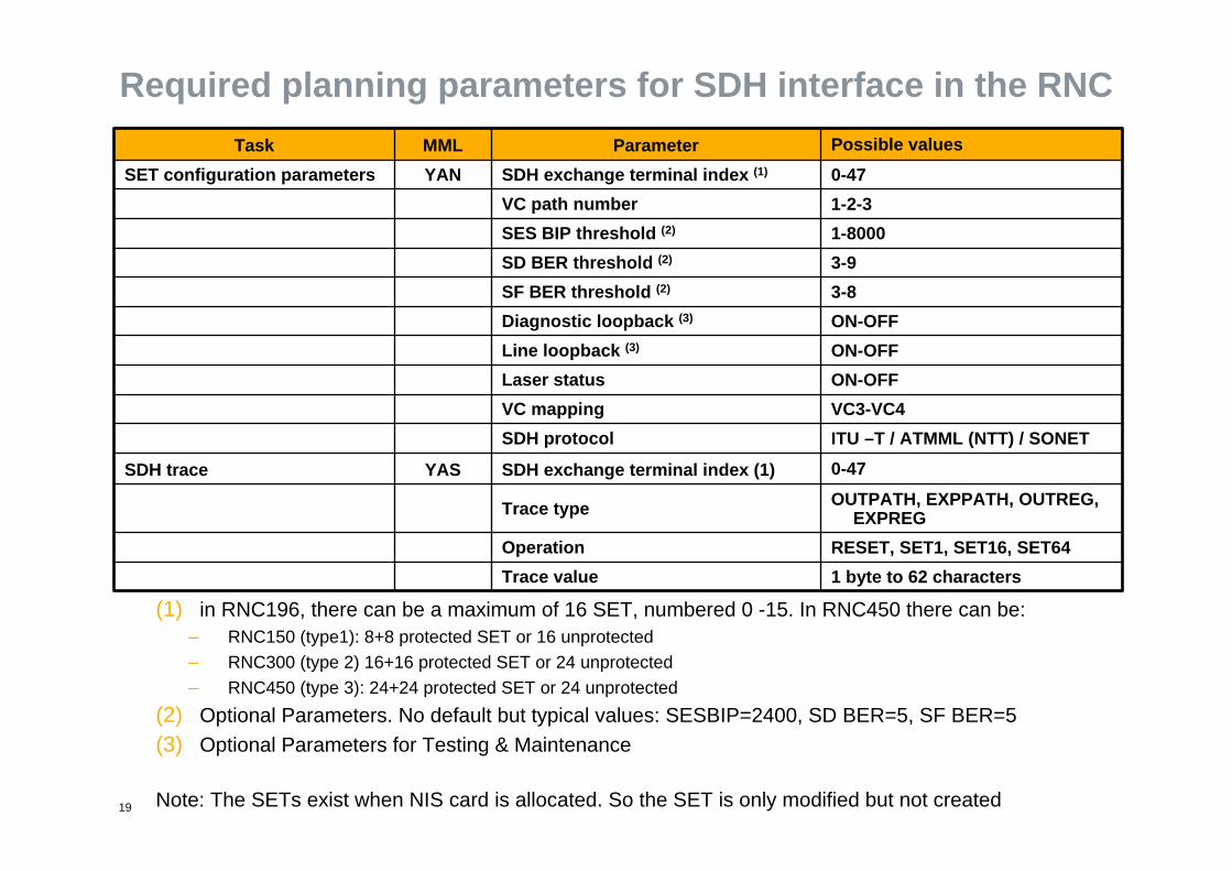
Required planning parameters for SDH interface in the RNC
(1) in RNC196, there can be a maximum of 16 SET, numbered 0 -15. In RNC450 there can be:– RNC150 (type1): 8+8 protected SET or 16 unprotected– RNC300 (type 2) 16+16 protected SET or 24 unprotected– RNC450 (type 3): 24+24 protected SET or 24 unprotected
(2) Optional Parameters. No default but typical values: SESBIP=2400, SD BER=5, SF BER=5(3) Optional Parameters for Testing & Maintenance
Note: The SETs exist when NIS card is allocated. So the SET is only modified but not created
ITU –T / ATMML (NTT) / SONETSDH protocol
1-2-3VC path number
1 byte to 62 charactersTrace valueRESET, SET1, SET16, SET64Operation
OUTPATH, EXPPATH, OUTREG, EXPREGTrace type
0-47SDH exchange terminal index (1)YASSDH trace
VC3-VC4VC mappingON-OFFLaser statusON-OFFLine loopback (3)
ON-OFFDiagnostic loopback (3)
3-8SF BER threshold (2)
3-9SD BER threshold (2)
1-8000SES BIP threshold (2)
0-47SDH exchange terminal index (1)YANSET configuration parametersPossible valuesParameterMMLTask

3GTPL – Session 7 – RNC Detailed Parameter Planning – JKl – 05.12.200820 © Nokia Siemens Networks
Required planning parameters for SDH protection group
OPT / COM (2) (parameter removed)Protection Protocol
1-720 wait to restore time (seconds)
SET index (3)Working section 2SET index (3)Working section 1MSP, ASPProtocol variant
REV-NONREV (1)Protection switching mode0-55Protection group idYWCSDH protection group
Possible valuesParameterMMLTask
(1) revertive or non-revertive mode (NONREV default, REV only for OPT!)(2) MSP 1 + 1 optimised protocol or MSP 1 + 1 compatible with 1: n protocol(3) Remote end to be set accordinglyNote: Only MSP bi-directional supported
3GTPL – Session 7 – RNC Detailed Parameter Planning – JKl – 05.12.200821 © Nokia Siemens Networks
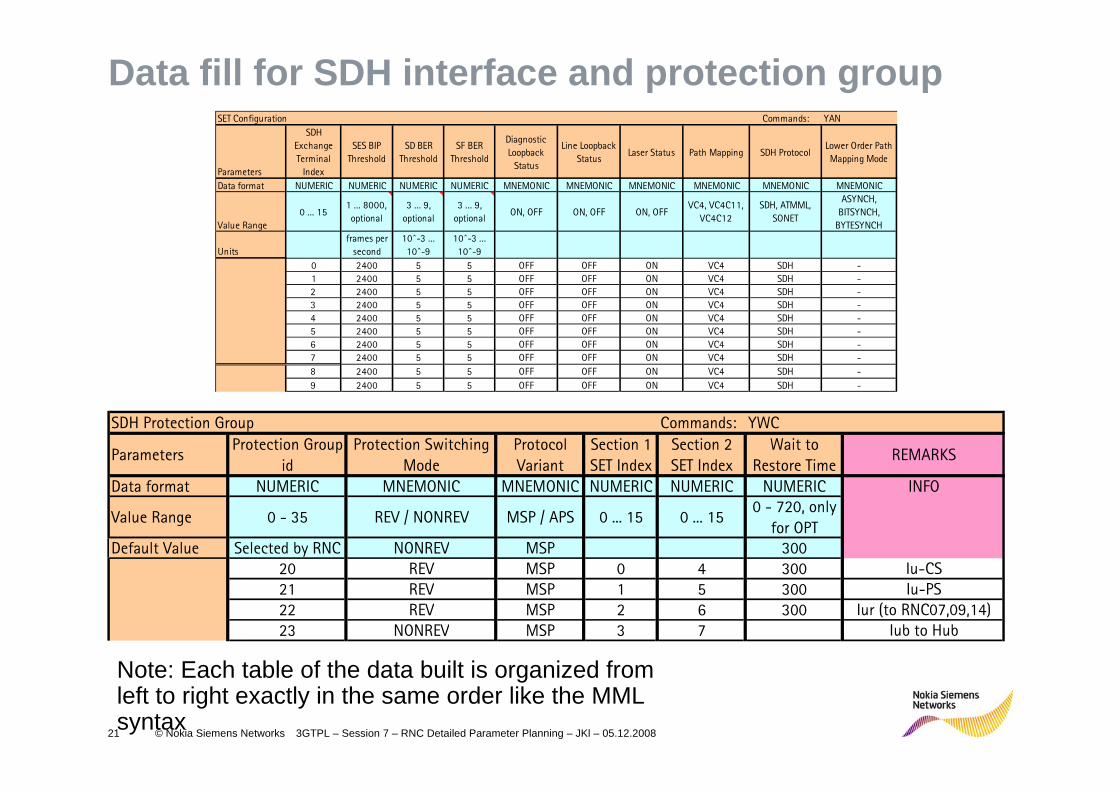
Data fill for SDH interface and protection groupSET Configuration Commands: YAN
Parameters
SDH Exchange Terminal
Index
SES BIP Threshold
SD BER Threshold
SF BER Threshold
Diagnostic Loopback
Status
Line Loopback Status
Laser Status Path Mapping SDH ProtocolLower Order Path Mapping Mode
Data format NUMERIC NUMERIC NUMERIC NUMERIC MNEMONIC MNEMONIC MNEMONIC MNEMONIC MNEMONIC MNEMONIC
Value Range0 ... 15
1 ... 8000, optional
3 ... 9, optional
3 ... 9, optional
ON, OFF ON, OFF ON, OFFVC4, VC4C11,
VC4C12SDH, ATMML,
SONET
ASYNCH, BITSYNCH,
BYTESYNCH
Unitsframes per
second10^-3 ... 10^-9
10^-3 ... 10^-9
0 2400 5 5 OFF OFF ON VC4 SDH -1 2400 5 5 OFF OFF ON VC4 SDH -2 2400 5 5 OFF OFF ON VC4 SDH -3 2400 5 5 OFF OFF ON VC4 SDH -4 2400 5 5 OFF OFF ON VC4 SDH -5 2400 5 5 OFF OFF ON VC4 SDH -6 2400 5 5 OFF OFF ON VC4 SDH -7 2400 5 5 OFF OFF ON VC4 SDH -8 2400 5 5 OFF OFF ON VC4 SDH -9 2400 5 5 OFF OFF ON VC4 SDH -
SDH Protection Group Commands: YWC
ParametersProtection Group
idProtection Switching
ModeProtocol Variant
Section 1 SET Index
Section 2 SET Index
Wait to Restore Time
REMARKS
Data format NUMERIC MNEMONIC MNEMONIC NUMERIC NUMERIC NUMERIC INFO
Value Range 0 - 35 REV / NONREV MSP / APS 0 ... 15 0 ... 150 - 720, only
for OPTDefault Value Selected by RNC NONREV MSP 300
20 REV MSP 0 4 300 Iu-CS21 REV MSP 1 5 300 Iu-PS22 REV MSP 2 6 300 Iur (to RNC07,09,14)23 NONREV MSP 3 7 Iub to Hub
Note: Each table of the data built is organized from left to right exactly in the same order like the MML syntax
3GTPL – Session 7 – RNC Detailed Parameter Planning – JKl – 05.12.200822 © Nokia Siemens Networks
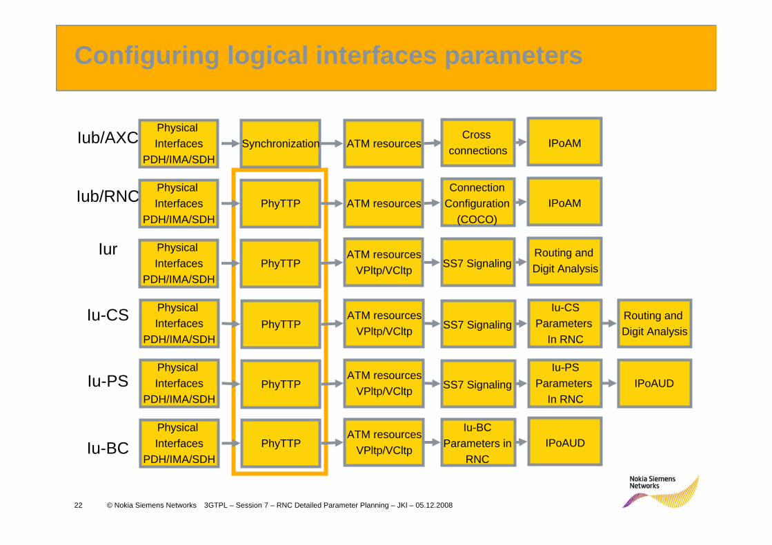
Configuring logical interfaces parameters
Iub/RNC
Iur
Iu-CS
Iu-PS
Iu-BC
Iub/AXCPhysical Interfaces
PDH/IMA/SDHSynchronization ATM resources
Cross connections
IPoAM
Physical Interfaces
PDH/IMA/SDHPhyTTP ATM resources
ConnectionConfiguration
(COCO)IPoAM
Physical Interfaces
PDH/IMA/SDHPhyTTP
ATM resourcesVPltp/VCltp SS7 Signaling
Routing and Digit Analysis
Physical Interfaces
PDH/IMA/SDHPhyTTP
ATM resourcesVPltp/VCltp SS7 Signaling
Iu-CSParameters
In RNC
Routing and Digit Analysis
Physical Interfaces
PDH/IMA/SDHPhyTTP
ATM resourcesVPltp/VCltp SS7 Signaling
Iu-PSParameters
In RNCIPoAUD
Physical Interfaces
PDH/IMA/SDHPhyTTP
ATM resourcesVPltp/VCltp
Iu-BCParameters in
RNCIPoAUD

3GTPL – Session 7 – RNC Detailed Parameter Planning – JKl – 05.12.200823 © Nokia Siemens Networks
Interfaces configuration flowchartPDH interface (E1 / T1 / JT1) SDH interface (VC3 / VC4)
PET
IMA Group
Physical Trail Termination Point – PhyTTP
Protection Group
SET
ATM Interface + Access Profile
Virtual Connections (VP & VC)
• The Physical layer Trail Termination Point (PhyTTP) is used to hide the properties of the physical resources from the upper protocol layers.
• It is configured between the physical layer and the ATM layer. • To detect failures in the ATM transmission, the physical layer supervises
the PhyTTP.

3GTPL – Session 7 – RNC Detailed Parameter Planning – JKl – 05.12.200824 © Nokia Siemens Networks
Required planning parameters for PhyTTP
(1) Defined in previous slides(2) This parameter identifies the type of the
payload in the data transfer. Possible values for SET and SDH protection group are ATM and PPP. The default is ATM. For PET and IMA group the only possible value is ATM.
(3) This parameter defines whether the payload is scrambled in the data transfer. Possible values for PPP type of payload are ON and OFF. The default is ON. For ATM type of payload this parameter cannot be given
ON-OFFPPP scrambling (3)
ATM, PPPPayload type (2)
1-3VC path number (1)
0-55SDH protection group (1)
0-23SET ID (1)
1-224IMA group id (1)
0-191PET ID (1)
1-588PhyTTP idYDCPhysical Trail Termination pointPossible valuesParameterMMLTask
PhyTTP Parameters Commands: YDC
Parameters PhyTTP Type IndexVC Path Number
Payload Type
PPP Scrambling
REMARKS
Data format NUMERIC MNEMONIC NUMERIC NUMERIC MNEMONIC MNEMONIC INFO
Value Range 1…588PET, IMA,
SET, PROTGROUP
PET: PET index,IMA: IMA group ID,
SET: SET index,PROTGROUP:
protection group ID
1 ... 3, only for SET and PROTGROUP, optional
ATM, PPP ON / OFF
UnitsDefault Value 1 ATM ON
100 PROTGROUP 20 ATM - Iu-CS101 PROTGROUP 21 ATM - Iu-PS102 PROTGROUP 22 ATM - Iur (to RNC07,09,14)103 IMA 10 ATM - Iur to RNC BLN01104 IMA 11 ATM - Iur to RNC BLN11105 PROTGROUP 23 ATM - Iub to Hub106 SET 8 ATM - Iub to Hub107 SET 9 ATM - Iub to Hub
Example for Data fill

3GTPL – Session 7 – RNC Detailed Parameter Planning – JKl – 05.12.200825 © Nokia Siemens Networks
Configuring logical interfaces parameters
Iub/RNC
Iur
Iu-CS
Iu-PS
Iu-BC
Iub/AXCPhysical Interfaces
PDH/IMA/SDHSynchronization ATM resources
Cross connections
IPoAM
Physical Interfaces
PDH/IMA/SDHPhyTTP ATM resources
ConnectionConfiguration
(COCO)IPoAM
Physical Interfaces
PDH/IMA/SDHPhyTTP
ATM resourcesVPltp/VCltp SS7 Signaling
Routing and Digit Analysis
Physical Interfaces
PDH/IMA/SDHPhyTTP
ATM resourcesVPltp/VCltp SS7 Signaling
Iu-CSParameters
In RNC
Routing and Digit Analysis
Physical Interfaces
PDH/IMA/SDHPhyTTP
ATM resourcesVPltp/VCltp SS7 Signaling
Iu-PSParameters
In RNCIPoAUD
Physical Interfaces
PDH/IMA/SDHPhyTTP
ATM resourcesVPltp/VCltp
Iu-BCParameters in
RNCIPoAUD

3GTPL – Session 7 – RNC Detailed Parameter Planning – JKl – 05.12.200826 © Nokia Siemens Networks
Interfaces configuration flowchartPDH interface (E1 / T1 / JT1) SDH interface (VC3 / VC4)
PET
IMA Group
Physical Trail Termination Point – PhyTTP
Protection Group
SET
ATM Interface + Access Profile
Virtual Connections (VP & VC)
• The Physical layer Trail Termination Point (PhyTTP) is used to hide the properties of the physical resources from the upper protocol layers.
• It is configured between the physical layer and the ATM layer. • To detect failures in the ATM transmission, the physical layer supervises
the PhyTTP.

3GTPL – Session 7 – RNC Detailed Parameter Planning – JKl – 05.12.200827 © Nokia Siemens Networks
ATM resources in the RNC
Physical layerSDH/ PDH / IMA
ATM IF
VPC
VPCVCCVCC
VCC
VCC
3. Create VPLtp
4. Create VCLtp1. Create ATM IF &
2. Access Profile
Note:VPLtp stands for Virtual Path Link Termination PointVCLtp stands for Virtual Channel Link Termination Point
• To create the ATM resources on the Iub, we should use the RNC RNW Object browser. For other interfaces we use MML.
• Nevertheless, the same parameters for ATM resources are used for the all RNC interfaces:– Iub– Iu-CS– Iu-PS– Iur– Iu-BC– All related SS7 signaling channels– O&M
• Iub VP/VC to created with CoCo objects• The needed resources are
– ATM interface– Access profile– VPLtp for CBR traffic– VPLtp for UBR traffic– VCLtp for CBR traffic– VCLtp for UBR traffic– VCLtp for UBR+ traffic (RAS06!)

3GTPL – Session 7 – RNC Detailed Parameter Planning – JKl – 05.12.200828 © Nokia Siemens Networks
Required planning parameters for ATM interface in the RNC
(1) Defined on previous slides(2) UNI = User-Network-Interface and NNI = Network-Network-Interface(4) Max VPI bits value is 8 for a UNI interface and 12 for a NNI. Consider limitations: Total
VPI/VCI bits for RNC is 14, for the AXC it’s 13(5) A PDH interface can support up to 7 VCI bits, while an SDH one supports up to 14 bits(6) UPC (Usage Parameter Control) and NPC (Network Parameter Control) stands for Policing
functionality. The default value is E (enabled). This means it is enables for CBR traffic. Note: Before RAS5.1 the bandwidth was also a parameter of the Access Profile. It was cancelled
the capacity is now directly derived from the PhyTTP.
E (Enabled), D (Disabled)UPC/NPC mode (6)
1-7 or 1-13Max VCI bits (5)
1-8 or 1-12Max VPI bits (4)
1-588ATM interface idLAFATM interface access profile1-588PhyTTP id (1)
UNI (Iub)/NNIInterface type (1) (2)
1-588ATM interface id (1)LACATM interface definition
Possible valuesParameterMMLTask

3GTPL – Session 7 – RNC Detailed Parameter Planning – JKl – 05.12.200829 © Nokia Siemens Networks
To show how the MML-command looks like, here are examples of the MML-syntax and the command itself for creating the ATM-interface and the Access Profile. Both commands refer to the 1st entry of the table above.
LAC:[<interface id> | <system select> def]: (UNI | NNI), <phyTTP>, [[LOCKED | UNLOCKED] | UNLOCKED def]; =>ZLAC:200:NNI,100;
LAF:<interface id>:<max VPI bits>:<max VCI bits>:<UPC/NPC mode>; => ZLAF:200:6:8;
Note: Default values can be skipped within the command!
Defining ATM Interface and corresponding Access Profile in RNC Data built
ATM Interface Commands: LAC Access Profile Command: LAC
ParametersInterface
IDInterface
TypePhyTTP ID
Administrative state
Max VPI Bits
Max VCI Bits
UPC/NPC Mode (Policing)
REMARKS
Data format NUMERIC MNEMONIC NUMERIC MNEMONIC NUMERIC NUMERIC MNEMONIC INFO
Value Range 1…588 UNI/ NNI 1..588LOCKED,
UNLOCKED1...8 (UNI)1..12 (NNI)
1..14E/D (ENABLED/
DISABLED)
Default Value First Free UNLOCKED ENABLED200 NNI 100 UNLOCKED 6 8 E Iu-CS201 NNI 101 UNLOCKED 8 6 E Iu-PS202 NNI 102 UNLOCKED 7 7 D Iur (RNC07,09,14)203 NNI 106 UNLOCKED 7 6 D Iur to RNC BLN01204 NNI 107 UNLOCKED 7 6 D Iur to RNC BLN11205 UNI 103 UNLOCKED 7 6 D Iub to Hub206 UNI 104 UNLOCKED 7 6 D Iub to Hub207 UNI 105 UNLOCKED 7 6 D Iub to Hub

3GTPL – Session 7 – RNC Detailed Parameter Planning – JKl – 05.12.200830 © Nokia Siemens Networks
Configuring Virtual Paths and Channels for ATM interface
Transmission interface, ATM interface
Create VPLtp
Create VCLtp
3GTPL – Session 7 – RNC Detailed Parameter Planning – JKl – 05.12.200831 © Nokia Siemens Networks
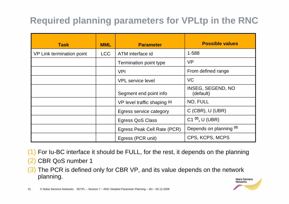
Required planning parameters for VPLtp in the RNC
(1) For Iu-BC interface it should be FULL, for the rest, it depends on the planning(2) CBR QoS number 1(3) The PCR is defined only for CBR VP, and its value depends on the network
planning.
CPS, KCPS, MCPSEgress (PCR unit)
Depends on planning (3)Egress Peak Cell Rate (PCR)
C1 (2), U (UBR)Egress QoS Class
C (CBR), U (UBR)Egress service category
NO, FULLVP level traffic shaping (1)
INSEG, SEGEND, NO (default)Segment end point info
VCVPL service level
From defined rangeVPI
VPTermination point type
1-588ATM interface idLCCVP Link termination point
Possible valuesParameterMMLTask
3GTPL – Session 7 – RNC Detailed Parameter Planning – JKl – 05.12.200832 © Nokia Siemens Networks
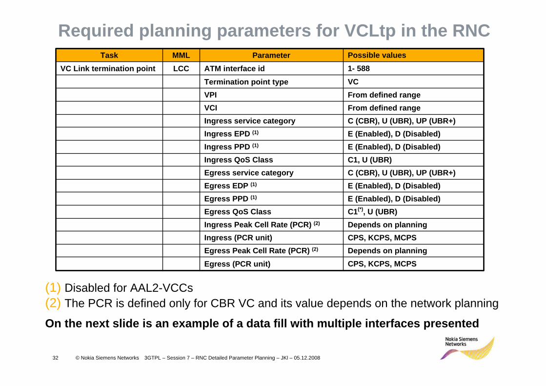
Required planning parameters for VCLtp in the RNC
(1) Disabled for AAL2-VCCs(2) The PCR is defined only for CBR VC and its value depends on the network planning
On the next slide is an example of a data fill with multiple interfaces presented
CPS, KCPS, MCPSEgress (PCR unit)Depends on planningEgress Peak Cell Rate (PCR) (2)
CPS, KCPS, MCPSIngress (PCR unit)Depends on planningIngress Peak Cell Rate (PCR) (2)
C1(*), U (UBR)Egress QoS ClassE (Enabled), D (Disabled)Egress PPD (1)
E (Enabled), D (Disabled)Egress EDP (1)
C (CBR), U (UBR), UP (UBR+)Egress service categoryC1, U (UBR)Ingress QoS ClassE (Enabled), D (Disabled)Ingress PPD (1)
E (Enabled), D (Disabled)Ingress EPD (1)
C (CBR), U (UBR), UP (UBR+)Ingress service categoryFrom defined rangeVCIFrom defined rangeVPI VCTermination point type1- 588ATM interface idLCCVC Link termination pointPossible valuesParameterMMLTask
3GTPL – Session 7 – RNC Detailed Parameter Planning – JKl – 05.12.200833 © Nokia Siemens Networks
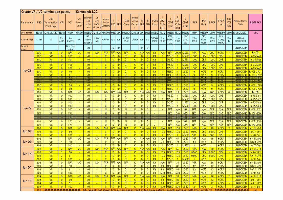
Create VP / VC termination points Command: LCC
Parameters IF IDLink
Termination Point Type
VPI VCIVPL
Service Level
Segment End
point Info
VP Level traffic
shaping
Ingress Servive
Category
I EPD
I PPD
I QoS Class
Egress Servive Categor
y
E EPD
E PPD
E QoS Class
I CDVT CLP=0&1
I CDVT Unit
E CDVT CLP=0&1
E CDVT Unit
I PCRI PCR Unit
E PCRE PCR Unit
max VCI bits
Administrative State
REMARKS
Data format NUM MNEMONIC NUM NUM MNEMOMNEMOMNEMOMNEMOMNE MNE MNEMOMNEMOMNE MNE MNEMONUM MNEM NUM MNEM NUM MNEMO NUM MNEMO NUM MNEMONIC INFO
Value Range 1…588 VC0…
40950…
65535VC
NO, INSEG,
SEGEND
FULL/ NO
C/U/UP E, D E, DC1/C2/ C3/U
C/U/UP E, D E, DC1/C2/ C3/U
1 ... 9999
USEC, MSEC,
SEC
1 ... 9999
USEC, MSEC,
SEC
10 ... 9999
CPS, KCPS, MCPS
10 ... 9999
CPS, KCPS, MCPS
0 ... 14
LOCKED, UNLOCKED
Default Value
First Free Value
NO D D D D UNLOCKED
200 VP 0 N/A VC NO NO N/A N/A N/A N/A C N/A N/A C1 N/A N/A 9999 MSEC N/A N/A 200 KCPS 7 UNLOCKED Iu-CS200 VC 0 100 - NO - C D D C1 C D D C1 1 MSEC 1 MSEC 1000 CPS 1000 CPS - UNLOCKED Iu-CS Sig1200 VC 0 101 - NO - C D D C1 C D D C1 1 MSEC 1 MSEC 1000 CPS 1000 CPS - UNLOCKED Iu-CS Sig2200 VC 0 102 NO C D D C1 C D D C1 1 MSEC 1 MSEC 1000 CPS 1000 CPS UNLOCKED Iu CS Sig3200 VC 0 103 NO C D D C1 C D D C1 1 MSEC 1 MSEC 1000 CPS 1000 CPS UNLOCKED Iu CS Sig4200 VC 0 104 NO C D D C1 C D D C1 1 MSEC 1 MSEC 1000 CPS 1000 CPS UNLOCKED Iu CS Sig5200 VC 0 105 NO C D D C1 C D D C1 1 MSEC 1 MSEC 1000 CPS 1000 CPS UNLOCKED Iu CS Sig6200 VC 0 106 - NO - C D D C1 C D D C1 1 MSEC 1 MSEC 1000 CPS 1000 CPS - UNLOCKED Iu-CS Sig7200 VC 0 107 - NO - C D D C1 C D D C1 1 MSEC 1 MSEC 1000 CPS 1000 CPS - UNLOCKED Iu-CS Sig8200 VC 0 40 - NO - C D D C1 C D D C1 111 USEC 111 USEC 9 KCPS 9 KCPS - UNLOCKED Iu-CS UP01200 VC 0 41 - NO - C D D C1 C D D C1 111 USEC 111 USEC 9 KCPS 9 KCPS - UNLOCKED Iu-CS UP02200 VC 0 42 NO C D D C1 C D D C1 111 USEC 111 USEC 9 KCPS 9 KCPS UNLOCKED Iu CS UP03200 VC 0 43 NO C D D C1 C D D C1 111 USEC 111 USEC 9 KCPS 9 KCPS UNLOCKED Iu CS UP04200 VC 0 44 NO C D D C1 C D D C1 111 USEC 111 USEC 9 KCPS 9 KCPS UNLOCKED Iu CS UP05200 VC 0 45 NO C D D C1 C D D C1 111 USEC 111 USEC 9 KCPS 9 KCPS UNLOCKED Iu CS UP06200 VC 0 46 NO C D D C1 C D D C1 111 USEC 111 USEC 9 KCPS 9 KCPS UNLOCKED Iu CS UP07200 VC 0 47 NO C D D C1 C D D C1 111 USEC 111 USEC 9 KCPS 9 KCPS UNLOCKED Iu CS UP08200 VC 0 48 NO C D D C1 C D D C1 111 USEC 111 USEC 9 KCPS 9 KCPS UNLOCKED Iu CS UP09200 VC 0 49 NO C D D C1 C D D C1 111 USEC 111 USEC 9 KCPS 9 KCPS UNLOCKED Iu CS UP10200 VC 0 50 NO C D D C1 C D D C1 111 USEC 111 USEC 9 KCPS 9 KCPS UNLOCKED Iu CS UP11200 VC 0 51 NO C D D C1 C D D C1 111 USEC 111 USEC 9 KCPS 9 KCPS UNLOCKED Iu CS UP12200 VC 0 52 NO C D D C1 C D D C1 111 USEC 111 USEC 9 KCPS 9 KCPS UNLOCKED Iu CS UP13200 VC 0 53 NO C D D C1 C D D C1 111 USEC 111 USEC 9 KCPS 9 KCPS UNLOCKED Iu CS UP14200 VC 0 54 NO C D D C1 C D D C1 111 USEC 111 USEC 9 KCPS 9 KCPS UNLOCKED Iu CS UP15200 VC 0 55 NO C D D C1 C D D C1 111 USEC 111 USEC 9 KCPS 9 KCPS UNLOCKED Iu CS UP16200 VC 0 56 NO C D D C1 C D D C1 111 USEC 111 USEC 9 KCPS 9 KCPS UNLOCKED Iu CS UP17200 VC 0 57 NO C D D C1 C D D C1 111 USEC 111 USEC 9 KCPS 9 KCPS UNLOCKED Iu CS UP18200 VC 0 58 - NO - C D D C1 C D D C1 111 USEC 111 USEC 9 KCPS 9 KCPS - UNLOCKED Iu-CS UP19200 VC 0 59 - NO - C D D C1 C D D C1 111 USEC 111 USEC 9 KCPS 9 KCPS - UNLOCKED Iu-CS UP20201 VP 0 N/A VC NO NO NA N/A N/A N/A C N/A N/A C1 N/A N/A 14 USEC N/A N/A 200 KCPS 6 UNLOCKED Iu-PS201 VC 0 100 - NO - C D D C1 C D D C1 1 MSEC 1 MSEC 1000 CPS 1000 CPS - UNLOCKED Iu-PS Sig1201 VC 0 101 - NO - C D D C1 C D D C1 1 MSEC 1 MSEC 1000 CPS 1000 CPS - UNLOCKED Iu-PS Sig2201 VC 0 102 - NO - C D D C1 C D D C1 1 MSEC 1 MSEC 1000 CPS 1000 CPS - UNLOCKED Iu-PS Sig3201 VC 0 103 - NO - C D D C1 C D D C1 1 MSEC 1 MSEC 1000 CPS 1000 CPS - UNLOCKED Iu-PS Sig4201 VC 0 100 - NO - U D D U U D D U - N/A N/A N/A N/A N/A N/A N/A N/A UNLOCKED Iu-PS UP01201 VC 0 101 - NO - U D D U U D D U - N/A N/A N/A N/A N/A N/A N/A N/A UNLOCKED Iu-PS UP02201 VC 0 110 NO U D D U U D D U N/A N/A N/A N/A N/A N/A N/A N/A UNLOCKED Iu PS UP03201 VC 0 111 NO U D D U U D D U N/A N/A N/A N/A N/A N/A N/A N/A UNLOCKED Iu PS UP04201 VC 0 120 NO U D D U U D D U N/A N/A N/A N/A N/A N/A N/A N/A UNLOCKED Iu PS UP05201 VC 0 121 NO U D D U U D D U N/A N/A N/A N/A N/A N/A N/A N/A UNLOCKED Iu PS UP06201 VC 0 130 NO U D D U U D D U N/A N/A N/A N/A N/A N/A N/A N/A UNLOCKED Iu PS UP07201 VC 0 131 NO U D D U U D D U N/A N/A N/A N/A N/A N/A N/A N/A UNLOCKED Iu PS UP08201 VC 0 140 NO U D D U U D D U N/A N/A N/A N/A N/A N/A N/A N/A UNLOCKED Iu PS UP09201 VC 0 141 NO U D D U U D D U N/A N/A N/A N/A N/A N/A N/A N/A UNLOCKED Iu PS UP10201 VC 0 150 NO U D D U U D D U N/A N/A N/A N/A N/A N/A N/A N/A UNLOCKED Iu PS UP11201 VC 0 151 NO U D D U U D D U N/A N/A N/A N/A N/A N/A N/A N/A UNLOCKED Iu PS UP12201 VC 0 160 NO U D D U U D D U N/A N/A N/A N/A N/A N/A N/A N/A UNLOCKED Iu PS UP13201 VC 0 161 NO U D D U U D D U N/A N/A N/A N/A N/A N/A N/A N/A UNLOCKED Iu PS UP14201 VC 0 170 - NO - U D D U U D D U - N/A N/A N/A N/A N/A N/A N/A N/A UNLOCKED Iu-PS UP15201 VC 0 171 - NO - U D D U U D D U - N/A N/A N/A N/A N/A N/A N/A N/A UNLOCKED Iu-PS UP16202 VP 0 N/A VC NO NO N/A N/A N/A N/A C N/A N/A C1 N/A N/A 100 USEC N/A N/A 10 KCPS 7 UNLOCKED Iur BLN07202 VC 0 50 - NO - C D D C1 C D D C1 105 USEC 105 USEC 9500 CPS 9500 CPS - UNLOCKED Iur07 UP1202 VC 0 100 - NO - C D D C1 C D D C1 2 MSEC 2 MSEC 500 CPS 500 CPS - UNLOCKED Iur07 Sig202 VP 1 N/A VC NO NO N/A N/A N/A N/A C N/A N/A C1 N/A N/A 67 USEC N/A N/A 15 KCPS 7 UNLOCKED Iur BLN09202 VC 1 50 - NO - C D D C1 C D D C1 71 USEC 71 USEC 14 KCPS 14 KCPS - UNLOCKED Iur09 UP1202 VC 1 100 - NO - C D D C! C D D C1 1 MSEC 1 MSEC 1 KCPS 1 KCPS - UNLOCKED Iur09 Sig202 VP 2 N/A VC NO NO N/A N/A N/A N/A C N/A N/A C1 N/A N/A 50 USEC N/A N/A 20 KCPS 7 UNLOCKED Iur BLN14202 VC 2 50 - NO - C D D C1 C D D C1 105 USEC 105 USEC 9500 CPS 9500 CPS - UNLOCKED Iur14 UP1202 VC 2 51 - NO - C D D C1 C D D C1 105 USEC 105 USEC 9500 CPS 9500 CPS - UNLOCKED Iur14 UP2202 VC 2 100 - NO - C D D C1 C D D C1 1 MSEC 1 MSEC 1 KCPS 1 KCPS - UNLOCKED Iur14 Sig203 VP 0 N/A VC NO NO N/A N/A N/A N/A C N/A N/A C1 N/A N/A 37 USEC N/A N/A 26 KCPS 7 UNLOCKED Iur BLN01203 VC 0 50 - NO - C D D C1 C D D C1 83 USEC 83 USEC 12 KCPS 12 KCPS - UNLOCKED Iur01 UP1203 VC 0 51 - NO - C D D C1 C D D C1 83 USEC 83 USEC 12 KCPS 12 KCPS - UNLOCKED Iur01 UP2203 VC 0 100 - NO - C D D C1 C D D C1 500 USEC 500 USEC 2 KCPS 2 KCPS - UNLOCKED Iur01 Sig204 VP 0 N/A VC NO NO N/A N/A N/A N/A C N/A N/A C1 N/A N/A 37 USEC N/A N/A 26 KCPS 7 UNLOCKED Iur BLN11204 VC 0 50 - NO - C D D C1 C D D C1 83 USEC 83 USEC 12 KCPS 12 KCPS - UNLOCKED Iur11 UP1204 VC 0 51 - NO - C D D C1 C D D C1 83 USEC 83 USEC 12 KCPS 12 KCPS - UNLOCKED Iur11 UP2204 VC 0 100 - NO - C D D C1 C D D C1 500 USEC 500 USEC 2 KCPS 2 KCPS - UNLOCKED Iur11 Sig205 XXXXXXXXXXXXXXXXXXXXXXXX Iub example not shown here as this would result in too many entries. Example continues with Core interfaces XXXXXXXXXXXXXXXXXXXXXX Iub
Iur 14
Iur 01
Iur 11
Iu-CS
Iu-PS
Iur 07
Iur 09

3GTPL – Session 7 – RNC Detailed Parameter Planning – JKl – 05.12.200834 © Nokia Siemens Networks
Connection Configuration with RNW Object Browser GUI (Graphical User Interface):• Graphical software application stored in the NEMU of the RNC, downloaded and started via Application
Launcher. • Use to configure Iub-related parameters, one CoCo per base station.• Automatically configures a lot of parameters by using templates and rules ->Recommended way to configure Iub• Link Termination points, A2EA address, Routing and Digit Analysis can be automatically created using CoCo.• If not using CoCo, all parameters need to be manually input (MML command).
Iub Connections to BTS

3GTPL – Session 7 – RNC Detailed Parameter Planning – JKl – 05.12.200835 © Nokia Siemens Networks
Configuring CoCo Objects for Iub
Iub/RNC
Iur
Iu-CS
Iu-PS
Iu-BC
Iub/AXC Physical Interfaces
PDH/IMA/SDHSynchronization ATM resources
Cross connections IPoAM
Physical Interfaces
PDH/IMA/SDHPhyTTP ATM resources
ConnectionConfiguration
(COCO)IPoAM
Physical Interfaces
PDH/IMA/SDHPhyTTP
ATM resourcesVPltp/VCltp SS7 Signaling
Routing and Digit Analysis
Physical Interfaces
PDH/IMA/SDHPhyTTP
ATM resourcesVPltp/VCltp SS7 Signaling
Iu-CSParameters
In RNC
Routing and Digit Analysis
Physical Interfaces
PDH/IMA/SDHPhyTTP
ATM resourcesVPltp/VCltp SS7 Signaling
Iu-PSParameters
In RNCIPoAUD
Physical Interfaces
PDH/IMA/SDHPhyTTP
ATM resourcesVPltp/VCltp
Iu-BCParameters in
RNCIPoAUD

3GTPL – Session 7 – RNC Detailed Parameter Planning – JKl – 05.12.200836 © Nokia Siemens Networks
RNC RNW Object Browser - CoCo CreationThe System will guide you for each step to input parameters
ATM Interface ID!

3GTPL – Session 7 – RNC Detailed Parameter Planning – JKl – 05.12.200837 © Nokia Siemens Networks
CoCo Configuration – Creating ATM Interface
ATM interface is done with MLL, but can be retrieved using Interface id inRNC RNW Object Browser

3GTPL – Session 7 – RNC Detailed Parameter Planning – JKl – 05.12.200838 © Nokia Siemens Networks
CoCo Configuration – Creating VPC

3GTPL – Session 7 – RNC Detailed Parameter Planning – JKl – 05.12.200839 © Nokia Siemens Networks
CoCo Configuration – Signaling links – C-NBAP

3GTPL – Session 7 – RNC Detailed Parameter Planning – JKl – 05.12.200840 © Nokia Siemens Networks
CoCo Configuration – Signaling links – D-NBAP

3GTPL – Session 7 – RNC Detailed Parameter Planning – JKl – 05.12.200841 © Nokia Siemens Networks
CoCo Configuration – Signaling links – AAL2sig

3GTPL – Session 7 – RNC Detailed Parameter Planning – JKl – 05.12.200842 © Nokia Siemens Networks
CoCo Configuration – AAL2 user plane links
New service category for user plane, UBR+• Parameters PCR, MDCR, UBRshare
Note! MDCR value for UBR+ NRT VCC cannot be zero unless the VCC is put in a Downlink VCC Bundle

3GTPL – Session 7 – RNC Detailed Parameter Planning – JKl – 05.12.200843 © Nokia Siemens Networks
CoCo Configuration – AAL2 user plane links –Bundle Association• New AAL2 user plane usage types, bundle definition and path type
definition
First in BundleFirst in Bundle

3GTPL – Session 7 – RNC Detailed Parameter Planning – JKl – 05.12.200844 © Nokia Siemens Networks
CoCo Configuration – AAL2 user plane links
From the Coco Object the following parameters will be configured automatically:
A2EA / PID / ANI / Route # / Endpoint ID / Digit Analysis Tree
Dynamic scheduling on/off per BTS
AAL2 buffer lengths are configurable
Bundle PCR definitions and EBS

3GTPL – Session 7 – RNC Detailed Parameter Planning – JKl – 05.12.200845 © Nokia Siemens Networks
Transport Bearer Tuning
• Activity factors are defined per RNC
• Uplink and downlink separately per bearer
• Main target PS bearers, but also other bearer types
3GTPL – Session 7 – RNC Detailed Parameter Planning – JKl – 05.12.200846 © Nokia Siemens Networks
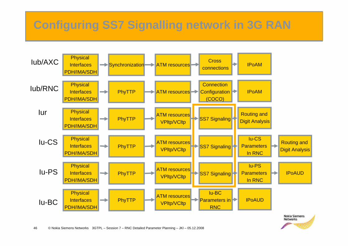
Configuring SS7 Signalling network in 3G RAN
Iub/RNC
Iur
Iu-CS
Iu-PS
Iu-BC
Iub/AXCPhysical Interfaces
PDH/IMA/SDHSynchronization ATM resources
Cross connections
IPoAM
Physical Interfaces
PDH/IMA/SDHPhyTTP ATM resources
ConnectionConfiguration
(COCO)IPoAM
Physical Interfaces
PDH/IMA/SDHPhyTTP
ATM resourcesVPltp/VCltp SS7 Signaling
Routing and Digit Analysis
Physical Interfaces
PDH/IMA/SDHPhyTTP
ATM resourcesVPltp/VCltp SS7 Signaling
Iu-CSParameters
In RNC
Routing and Digit Analysis
Physical Interfaces
PDH/IMA/SDHPhyTTP
ATM resourcesVPltp/VCltp SS7 Signaling
Iu-PSParameters
In RNCIPoAUD
Physical Interfaces
PDH/IMA/SDHPhyTTP
ATM resourcesVPltp/VCltp
Iu-BCParameters in
RNCIPoAUD

3GTPL – Session 7 – RNC Detailed Parameter Planning – JKl – 05.12.200847 © Nokia Siemens Networks
What is Signalling ?
• Definition: any transfer of data that enables speech and data connections between users
• In PSTN signalling is needed only for:– call establishing– call release – call maintaining
• In GSM/WCDMA signalling is needed for:– handle speech and data connection (set up, supervise and release a call)– handle mobility management (location update, handover)– handle subscriber administration (including all basic and supplementary GSM services)
• In GSM/WCDMA: signalling is any transfer of data that enables speech and data connection between users and supports mobility management and GSM services handling

3GTPL – Session 7 – RNC Detailed Parameter Planning – JKl – 05.12.200848 © Nokia Siemens Networks
A interface
Gn interface
3G-SGSN
Iu-CS
Iu-PS
Iur
S-AXC
Iub
Iub
UNI
UNI
UNI
NNI
NNI
NNI
RNC
BTS
BTS
BTS
BTSBTS
BTS
BTS
BTS
RNC
MGW
MSS/MSC
GGSN
SGSN
SS7 Signaling
SS7SS7
SS7SS7
SS7SS7

3GTPL – Session 7 – RNC Detailed Parameter Planning – JKl – 05.12.200849 © Nokia Siemens Networks
Protocol Structures for RNCs Logical Interfaces
TransportNetworkLayer
RadioNetworkLayer RANAP Iu User Plane
Protocol
Transport NetworkUser Plane
Transport NetworkUser Plane
ATM
Transport NetworkControl Plane
Physical Transmission layer
AAL5
SCCPMTP-3b
SSCF-NNISSCOP
AAL5
GTP-UUDPIP
User PlaneControl Plane
SAAL
TransportNetworkLayer
RadioNetworkLayer
Q.2630.1
D-NBAP
DCH FP
AAL2
Transport NetworkUser Plane
ATM
Transport NetworkControl Plane
Physical Transmission layer
AAL5
SSCF-UNI
SSCOPAAL5
Q.2150.2SSCF-UNI
SSCOP
RACH
FP
FACH
FP
PCH FP
DSCH
FP
CPCH
FP
User PlaneControl Plane
AAL5
SSCF-UNI
SSCOP
C-NBAP
Transport NetworkUser Plane
SAAL
IubTransportNetworkLayer
RadioNetworkLayer
Q.2630.1
RNSAP DCH FP
AAL2
Transport NetworkUser Plane
Transport NetworkUser Plane
ATM
Control Plane
Transport NetworkControl Plane
User Plane
Physical Transmission layer
AAL5
SCCPMTP-3b
SSCF-NNISSCOP
Q.2150.1
CCH FP
SAAL
Iur
IuPSTransportNetworkLayer
RadioNetworkLayer
Q.2630.1
RANAP DCH FP
AAL2
Transport NetworkUser Plane
Transport NetworkUser Plane
ATM
Control Plane
Transport NetworkControl Plane
User Plane
Physical Transmission layer
CCH FP
SAAL
IuCS
AAL5
SCCPMTP-3b
SSCF-NNISSCOP
Q.2150.1
No SS7 on Iub!

3GTPL – Session 7 – RNC Detailed Parameter Planning – JKl – 05.12.200850 © Nokia Siemens Networks
AAL2 Signalling
All Signalling in One Picture
Physical LayerATM Layer
SSCF-UNI SSCF-NNI
MTP3
AAL5
SSCOPSAALUNI
SAALNNI
SCCPRANAP RNSAP SCMG
SNM SNT
Iub Iur,IuCS
IuCS,IuPS Iur SS7 SS7 SS7
As a rough analogy to the TCP/IP world you may compare:SCCP~TCP/UDP,MTP3~IPSAAL~Layer 2 (Ethernet, PPP, …)

3GTPL – Session 7 – RNC Detailed Parameter Planning – JKl – 05.12.200851 © Nokia Siemens Networks
Protocol related abbreviations/explanationsSSCF: Service Specific Coordination FunctionSCCP: Signaling Connection Control PartSSCOP: Service Specific Connection Oriented Protocol
SAAL: Signaling ATM Adaptation Layer (= SSCF + SSCOP + AAL5)UNI: User-Network-Interface (Iub)NNI: Network-Network-Interface (Iur & Iu)Q.2150.1 is a signaling transport converter for UNI, needed to adapt the AAL2 signalling
protocol to lower layersQ.2150.2 is a signaling transport converter for NNIQ.2630.1 AAL2 signaling capability set 1 GTP-U: GPRS Tunneling Protocol-User planeUDP: User Datagram ProtocolMTP-3b: Message Transfer Part Level 3 broadbandRANAP: Radio Access Network Application PartRNSAP: Radio Network Subsystem Application PartSCMG: SCCP ManagementSNM: Signaling Network ManagementSNT: Signaling Network Testing and Maintenance

3GTPL – Session 7 – RNC Detailed Parameter Planning – JKl – 05.12.200852 © Nokia Siemens Networks
SS7 Network Structure (1)Signalling Points: Nodes in an SS7 network are called signalling points (SP’s):Types of signalling points: • SPC: Signalling Point Code is a binary code uniquely identifying a signalling point in a signalling network• SEP: Signalling End Point is a network node that originates and/or terminates signalling messages• STP: Signalling Transfer Point is a signalling point that transfers messages towards a destination point• The Signalling Point is usually in the RNC a SEP and in the MGW a SEP
In SS7 there are 4 Signalling Networks:• NA0 – National zero, usually used in PSTN and inter-operator connections • NA1 – National one, used by GSM and other operators• IN0 – International zero, used for connections to international gateway • IN1 – international one (usually spare)• A SP can operate in a maximum of 4 signalling networks (e.g. MSC)• In 3G RAN we always use NA0 or NA1

3GTPL – Session 7 – RNC Detailed Parameter Planning – JKl – 05.12.200853 © Nokia Siemens Networks
SS7 Network Structure (2)• Signalling Link - a signalling link connects two signalling points. In RAN, one signalling
link is associated to one signalling VCC. All SS7 signalling links in 3G RAN (both ED2 and RAN04), are based on ATM transport and AAL5 adaptation layer.
• Signalling Link Set - a set of signalling links directly connecting two signalling pointsTraffic between SP’s is generally load-shared between all links in a linkset
• Signalling Route - a predetermined path described by a succession of signalling points that may be traversed by signalling messages directed by a signalling point towards a specific destination point
• Signalling Route Set - combination of all permitted signalling routes that may be used to pass signalling messages from a signalling point to a specific destination
SEPSEP STPSTP SEPSEPSTPSTP
ignalling End Point Signalling End PointSignalling Transfer Point
STPSTP
SEP STP SEP
RNSAP
SCCP
MTP
SCCP
MTP
RNSAP
SCCP
MTP
Network Element A Network Element B Network Element C
3GTPL – Session 7 – RNC Detailed Parameter Planning – JKl – 05.12.200854 © Nokia Siemens Networks
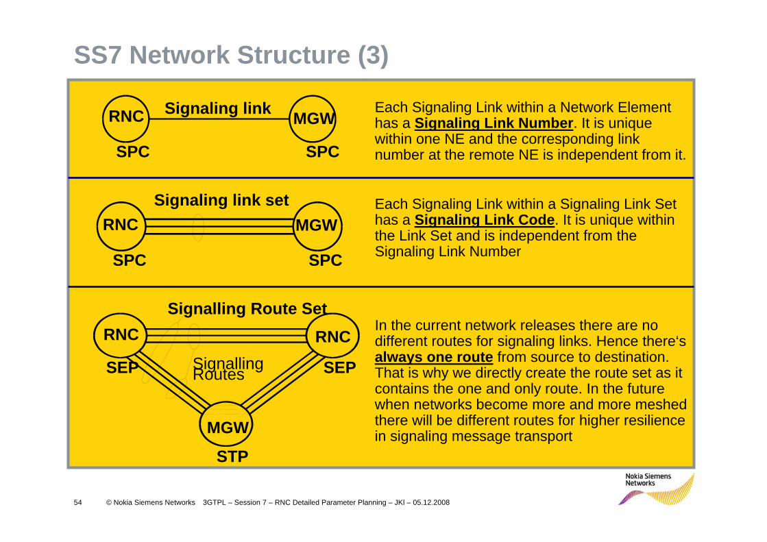
SS7 Network Structure (3)
RNC MGW
SPC SPC
Signaling link
RNC MGW
SPC SPC
Signaling link set
RNC RNC
MGW
SignallingRoutes
Signalling Route Set
SEP SEP
STP
Each Signaling Link within a Network Element has a Signaling Link Number. It is unique within one NE and the corresponding link number at the remote NE is independent from it.
Each Signaling Link within a Signaling Link Set has a Signaling Link Code. It is unique within the Link Set and is independent from the Signaling Link Number
In the current network releases there are no different routes for signaling links. Hence there‘s always one route from source to destination. That is why we directly create the route set as it contains the one and only route. In the future when networks become more and more meshed there will be different routes for higher resilience in signaling message transport

3GTPL – Session 7 – RNC Detailed Parameter Planning – JKl – 05.12.200855 © Nokia Siemens Networks
ICSU
2
ICSU
3
VPI 1
VCI 60; SLC 0
SPC= 3100
MGW01
SPC= 1034
SGSN01SPC= 1032
Signalling Network : NA0
SLN 2
SLN 4
SLN 3
RNC02SPC= 3101
VPI1VCI 34; SLC 0VCI 35; SLC 1
VPI0VCI 34; SLC 0
VPI0VCI 34; SLC 0
VPI1VCI 34; SLC 0
RNC01SLN 0SLN 1
MEGACO H.248 MSS01
SPC= 2001
• Signallink Link Number is unique within Network Element
• Signalling Link Code is unique within Link Set
RNC SS7 Configuration Example
3GTPL – Session 7 – RNC Detailed Parameter Planning – JKl – 05.12.200856 © Nokia Siemens Networks
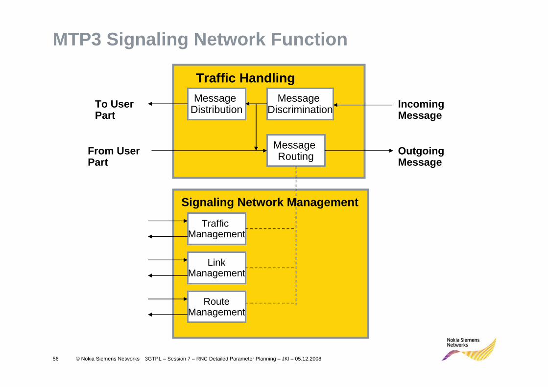
MTP3 Signaling Network Function
Message Distribution
Message Discrimination
Message Routing
Traffic Management
LinkManagement
RouteManagement
Traffic Handling
Signaling Network Management
To User Part
From User Part
Incoming Message
Outgoing Message

3GTPL – Session 7 – RNC Detailed Parameter Planning – JKl – 05.12.200857 © Nokia Siemens Networks
What is needed before setting SS7 in 3G RAN• Get the signalling point code allocation scheme from telecommunications administration. The
allocation scheme contains the signalling point codes to be used in the own signalling network.
• Define the format of the SPC: length 14, 16 or 24 bits, Also define if the signalling point code should be allocated into sub-fields e.g. 3-8-3 bits or 8-8-8 bits format
• Define the signalling network allocation: Find out if, for example, RNCs are configured to NA1 signalling network and MGW to NA0 signalling network.
• Define the network structure concerning SEPs and STPs
• Define the physical transmission paths and the VPI/VCI numbering plan.
• In case of IP transmission, define source and destination IP addresses.
• Determine signalling traffic between two NEs in order to define the link size and capacity
• Identify the signalling links within a link set by defining signalling link code (SLC).
• MVI: Find out if there are any restrictions concerning the other vendors' interconnecting network elements concerning timer values, address field of messages or managementprocedures. Note: This mainly concerns the signalling link set parameter set!
• Find out what network elements are included in the signalling network where the SCCP (e.g. RANAP, RNSAP) exists and define the applications that exist in different network elements and the type of addressing (GT or SPC and SSN) used to send messages to them
• Find out what kind of global titles are used (for example, if roaming agreements and used IN services affect the global titles)
NSN

3GTPL – Session 7 – RNC Detailed Parameter Planning – JKl – 05.12.200858 © Nokia Siemens Networks
SS7 signalling in RAN-Core Rel4 CS Core
Iub Iu-CS /Iur MEGACO (H248)on SIGTRAN MSS
SS7 signalling in RAN-Core PS
Iub Iu-PS
When R99 CS-Core network will be upgraded to R4, major HW changes must be carried out. The MSC will be replaced by an MSS (MSC-Server). The MSS controls the interconnected MGWs and only signaling traffic is transmitted and the user plane traffic is transported between MGWs. The signaling point of the MGW is then a STP, RANAP messages are forwarded to MSS, ALCAP(AAL2sig) messages are processed
RNC SGSNBTS
BTS RNC RNC/
MGW

3GTPL – Session 7 – RNC Detailed Parameter Planning – JKl – 05.12.200859 © Nokia Siemens Networks
SS7 network structure (Rel4 Core)
Signalling links
Signalling link set
MEGACO
Signalling links
Signalling link set
Direct signalling Route
Indirect signalling Route
MSSRNC MGW
STP for RANAP messagesSEP for ALCAP
• Since Rel4 was introduced all new Core networks are based on this release• Existing Core networks did or will migrate sooner or later• With Rel4 the MSC becomes superfluous, the switching will be done by the
MGW but controlled by the MSS (MSC Server). This is called Softswitch!• Therefore the ALCAP (AAL2sig + MTP3) will be terminated in the MGW but
the RANAP will be terminated in the MSS• Both protocols can use the same signalling link or can be in two different
links. – In case of 2 VCC the traffic passes the MGW transparently– In case of 1 VCC the MGW acts as a STP (Signalling Transfer Point) for RANAP
messages• The IP connection from the MSS to the MGW is called MEGACO (Media
Gateway Control Protocol ) or H248 and is controlling the MGW• Several MGW could be connected to 1 MSS via the SIGTRAN links• The connection between MGWs is the Nb-interface
MEGACO on SigtranRNC
3G-
SGSN
MGW

3GTPL – Session 7 – RNC Detailed Parameter Planning – JKl – 05.12.200860 © Nokia Siemens Networks
MEGACO / H.248 --Media Gateway Control protocol• The H.248 protocol is used in the Mc interface between MSC Server and MGW
Rel.4. • MSC Server controls the user plane terminations and contexts in MGW Rel.4
through the Mc interface.
L
MGW MGW
MEGACO/ H.248
ATM/IP/TDM
MSS/VLR
MGW
GCS MAP/INAPTCAP
SCCP
M3UA
BICCISUP
HLR/EIR/ACMAP / INAP
TCAP
SCCP
M3UA
MSS/VLR
RANAPMAP/INAPTCAP
SCCP
M3UA
BICCISUP
RNCRANAP
SCCP
MTP3b
PSTNExchange
SCCP
MTP3
ISUP
CCS7 in UMTS Rel 4 Network

3GTPL – Session 7 – RNC Detailed Parameter Planning – JKl – 05.12.200861 © Nokia Siemens Networks
MSS Interfaces & Protocols• RANAP and BSSAP for radio access control
• BICC and SIP for bearer independent call control
• ISUP, TUP and IUP for TDM trunk call control
• All above SS7 signaling over SIGTRAN via MGW
• H.248 for MGW control
• CAS and PBX calls are connected to the Integrated MSS
Iu-CS
RNC
MSCServer
AAL2ATM
TDM
H.248IP
MSCServer
Mc
MGW
Nc
AAL2/AAL5ATM Nb
McSigtran
IP
BICC, SIPATM/IP
HLR
MAP CAP
MGWRTPIP
RANAPAAL5/ATM SS7
BSC
SigtranIP
ATDM
BSSAP
H.248IP
ServicesServices
PSTNPSTN

3GTPL – Session 7 – RNC Detailed Parameter Planning – JKl – 05.12.200862 © Nokia Siemens Networks
SS7 definition in the RNC
• The following steps are needed in order to activate the SS7 signalling in the RNC, and inter connect it to the rest of the SS7 network:1. Define the RNC’s own MTP parameters and needed services (defined once during RNC
Setup)2. Define the RNC’s own SCCP signalling point and subsystems (defined once during RNC
Setup)3. Create the SS7 signalling links4. Create the SS7 signalling link set5. Create the needed route set
Own SP
Services
SCCPSubsystems
Iu-CS Iu-PS Iur
MTP
SCCP AAL2 SNM SNT
RAN
AP
RN
SAP
RAN
AP
RAN
AP
RN
SAP
Local RemoteMGW 3G-SGSN Neighbour RNC
MGW 3G-SGSN Neighbour RNC
Dest=xx-> STP=yyDest=nn-> STP=mm
Signalling over IP between RNC and MGW is a new feature. This is not directly related to R4.
Due to IP settings Signallingover IP is handled later in the session after Iu-PS interface.

3GTPL – Session 7 – RNC Detailed Parameter Planning – JKl – 05.12.200863 © Nokia Siemens Networks
Required planning parameters for own Signalling Point
Y / N (default: Y)Service exists for user part(3)
See table next slide, all values default!Primary Process Family (4)
See table next slide, all values default!Secondary Process Family (4)
Y / N (default: Y)Service exists for STP (2)
00 – SNM (signalling network management messages)01 – SNT (signalling network testing and maintenance)03 – SCCP (signalling connection control part)0c – AAL2 (AAL type 2 signalling protocol )Service Index & NameNPC
Define own SS7 Services (1)
A/A&B/A&B&C/ A&B&C&DSPC subfield lengths
1….4Number of SPC subfields
ITU-T for 14 bit SPC code of ITU-T SS7 standardJAP16 for 16 bit SPC code of Japan SS7 standardCHI24 for 24 bit SPC code of China SS7 standardANSI for 24 bit SPC code of ANSI SS7 standardSS7 standard
SEP / STPSignalling Point Type
1 to 5 ASCII charactersSignalling Point Name
Get from Core PlannerSignalling Point Code
NA0 / NA1 / IN0 / IN1Signalling Network usedNRPDefine own signalling pointPossible valuesParameterMMLTask
(1) Usually the entire command is executed the same way for every RNC. All settings are fixed to default(2) With this parameter you define whether the service exists for the STP messages. If a service exists for the STP messages, the
signalling messages concerning the service are switched forwards.(3) With this parameter you define whether the service exists for the user parts of own signalling point. If a service exists for the own
user parts, the signalling messages concerning the service are transmitted to the network element's own user parts.(4) Settings for Primary and Secondary Process Family are fixed. They present a subset of parameters respectively software
modules.

3GTPL – Session 7 – RNC Detailed Parameter Planning – JKl – 05.12.200864 © Nokia Siemens Networks
R N C S S 7 S e rvice s Commands: NPC
Signaling netw ork used ***
Service Indicator Index
Service Indicator Name
Service existing for STP
messages
Service existing for user part of ow n signalling
point
Primary Process Family
Secondary Process Family REMARKS ACTION
M NEM ONIC NUM ER IC M NEM ONIC M NEM ONIC M NEM ONIC NUM ER IC NUM ER IC INFO INFO
NA0 / NA1/ IN0 / IN1 0…FSNM /SNT/SCCP/
AAL2 Y/N Y/N 1…FFFF 1…FFFF
NA0 00 SNM Y Y 007F 006DNA0 01 SNT Y Y 007FNA0 03 SCCP Y Y 0208 010FNA0 0C AAL2 Y Y 0452
SS7 definition in the RNC – Step 1Define the RNC’s own MTP parameters and needed services
RNC SS7 Own Signa lling Point Commands: NRP
Signaling netw ork used ***
RNC Signalling Point Code
RNC Signalling Point Name
Ow n Signalling Point Type
SS7 standard SPC Subfields SPC Subfield Length
REMARKS ACTION
M NEM ONIC NUM ERIC STRING M NEM ONIC M NEM ONIC NUM ERIC NUM ERIC INFO INFO
NA0 /NA1/IN0 /IN11…5
ALPHANUMERIC CHARACTERS
STP/SEP/DEL/REC/USP/IWF
ITU-T/JAP16 / CHI24 /ANSI 1…4
A/A&B/A&B&C/ A&B&C&D
NA0 3100 RNC01 SEP ITU-T 1 A
MTP
SCCP AAL2 SNM SNTSubsytems(RANAP/RNSAP)
Iu-CS Iu-PS Iur
Note: These to creations are usually done during RNC first setup

3GTPL – Session 7 – RNC Detailed Parameter Planning – JKl – 05.12.200865 © Nokia Siemens Networks
Local Remote
SCCP
RAN
AP
RN
SAP
RAN
AP
RAN
AP
RN
SAP
MSS 3G-SGSN Neighbor RNCSCCP
Subsystems
SS7 definition in the RNC – Step 2Define the RNC’s own SCCP signalling point and subsystems
RNC SCCP SUBSYSTEMS Commands: NFB, NFD
Parameters
Signalling NetworkSignalling Point
CodeSignalling Point
Name
Signalling Point Parameter Set
Number
Subsystem Number
Subsystem Name
Subsystem Parameter
Set Number
Subsystem Status Test
REMARKS
Data formatMNEMONIC
NUMERIC or HEXADECIMAL
STRING HEXADECIMAL NUMERIC STRING NUMERIC MNEMONIC INFO
Value RangeNA0,NA1,IN0,IN1 1…5 characters
1 ... FE(8E = RANAP, 8F = RNSAP)
1…5 characters
0..63 Y/N
UnitsDefault Value YExample NA0 0400 HK1 0 8E RANAP 0 Y
NA0 2A24 RNB06 0 8E RANAP 0 N Local SCCPNA0 2A24 RNB06 0 8F RNSAP 0 N Local SCCP
NA0 2D82 MSS01 2 8E RANAP 0 N Remote SCCP (MSS)
NA0 2F4E SGN01 0 8E RANAP 0 N Remote SCCP (SGSN)
NA0 2A44 RNB01 0 8F RNSAP 0 N Remote SCCP RNC BLN01NA0 2A39 RNB07 0 8F RNSAP 0 N Remote SCCP RNC BLN07NA0 2A0A RNB09 0 8F RNSAP 0 N Remote SCCP RNC BLN09NA0 2A12 RNB11 0 8F RNSAP 0 N Remote SCCP RNC BLN11NA0 2AA1 RNB14 0 8F RNSAP 0 N Remote SCCP RNC BLN14
In addition to the RNC own SPC, the destination network element signalling point code (DPC) and the signalling network previously defined, the following parameters should be planned in order to define the SCCP subsystems

3GTPL – Session 7 – RNC Detailed Parameter Planning – JKl – 05.12.200866 © Nokia Siemens Networks
Signaling Point and Subsystem Parameter Set NumberIn the RNC we have extra parameter sets which do not appear in the data built. This applies for the Signaling Point, the Subset and for the Signal link Links and Routes as well. These sets usually exist already in the RNC in different editions (set0, set1 etc.) and contains quite some parameters. In other words depending on the connected signaling point (equipments SS7 attributes)a specific set is chosen. Even then it is possible that some parameters have to be modified. This is usually done by SS7 planners familiar with the details, decisions might be based on IOTs.
SCCP Subsystem Parameter SetSCCP Subsystem Parameter SetThis set contains 14 parameters which are usually not modified. The Set0 is normally used. Set name is „General“Each set contains the following parameters:
•Q714_T_COORD_CHG•Q714_T_IGN_SST•A_INTERF_APPLIC•A_INTERF_ERR_IGNORED•TRANSLATION_SELECT•CALLING_ADDR_MODIFICATION•CSCC_ALLOWED_OUT•CSCC_ALLOWED_IN•TRANSLATE_AT_DPC_IF_DPC_SSN_GT•TC_TRANSACTION_IDS_THRESHOLD•SEND_CALLING_SSN_IF_RI_SSN•SEND_CALLING_SPC_SSN_IF_RI_GT•KEEP_CLD_GT_IF_RI_SSN•IMMEDIATE_STATE_INFO
SCCP Subsystem Parameter SetThis set contains 27 parameters. The red high-lighted parameters are usually modified in a MVI environment. There are 4 sets:- Set 0 Blue Book (usually used for Nokia equipment)
- Set 1 A-ter- Set 2 White Book- Set 3 ITU3Each set contains the following parameters:•Q714_T_CONN_EST•Q714_T_IAS•Q714_T_IAR•Q714_T_REL•Q714_T_INT•Q714_T_RES•Q714_T_REP_REL•Q714_T_STAT_1ST•Q714_T_STAT_INC•Q714_T_STAT_MAX•A_INTERFACE•WHITE_BOOK_MGMT_USED•SS_MANAGEMENT_USED•XUDT_USED
•UDT_DENIED•SEG_X_THRES•SEG_Y_THRES•TCAP_LOAD_SHARING_USED•TCAP_LOAD_SHARING_USED•ADD_DPC_IF_RI_SSN•ADD_GT_IF_RI_SSN•ADD_DPC_IF_RI_GT•ANALYSE_ROOT_OF_CALLING_GT•ALLOWED_GTI_VALUES•SSA_FILTER_TIMER•SSP_FILTER_TIMER•LUDT_USED•CO_SEGM_USED
Usually the TRS Planner does not get in touch with the details of the parameter subsets!

3GTPL – Session 7 – RNC Detailed Parameter Planning – JKl – 05.12.200867 © Nokia Siemens Networks
SS7 definition in the RNC – Step 3 & 4 Create SS7 Signalling Links and Signalling Link Sets
RNC SS7 Link and Link Set Parameters Command: NCS Command: NSC
Parameters
Signalling Link Number
Ext Interface ID Number
External VPI
External VCI
Unit TypeUnit
NumberParameter
Set Signalling Point Code
Signalling Link Set Name
SLC (Signalling Link Code)
Signalling Link Priority
REMARKS
Data format NUMERIC NUMERIC NUMERIC NUMERIC MNEMONIC NUMERIC NUMERIC NUMERIC String NUMERIC NUMERIC INFO
Value RangeDynamic 1…588 0…4095 1…65535
ICSU / RRMU
Limited by no. of ICSU 0…63 0000-3FFF 1-5 ALPHANUMERI
CHARCATERS 0…15 0…15
Default Value First Free value ICSU 50 200 0 100 ICSU 0 0 2DA0 MGW03 0 0 Iu-CS1 200 0 101 ICSU 1 0 2DA0 MGW03 1 0 Iu-CS2 200 0 102 ICSU 2 0 2DA0 MGW03 2 0 Iu-CS3 200 0 103 ICSU 3 0 2DA0 MGW03 3 0 Iu-CS4 200 0 104 ICSU 4 0 2DA0 MGW03 4 0 Iu-CS5 200 0 105 ICSU 5 0 2DA0 MGW03 5 0 Iu-CS6 200 0 106 ICSU 6 0 2DA0 MGW03 6 0 Iu-CS7 200 0 107 ICSU 7 0 2DA0 MGW03 7 0 Iu-CS9 201 0 100 ICSU 8 5 2F4E SGLS1 0 0 Iu-PS10 201 0 101 ICSU 9 5 2F4E SGLS1 1 0 Iu-PS11 201 0 102 ICSU 10 5 2F4E SGLS1 2 0 Iu-PS12 201 0 103 ICSU 11 5 2F4E SGLS1 3 0 Iu-PS13 202 1 100 ICSU 12 0 2A44 LSB01 0 0 Iur 0114 202 2 100 ICSU 13 0 2A39 LSB07 0 0 Iur 0715 202 0 100 ICSU 14 0 2A0A LSB09 0 0 Iut 0916 203 0 100 ICSU 15 0 2A12 LSB11 0 0 Iur 1117 204 0 100 ICSU 16 0 2AA1 LSB14 0 0 Iur 14
MTP
SCCP AAL2 SNM SNTSubsytems(RANAP/RNSAP)
Iu-CSsigIu-PSsigIursig
Describes properties of links & link set

3GTPL – Session 7 – RNC Detailed Parameter Planning – JKl – 05.12.200868 © Nokia Siemens Networks
Parameters for Signaling Links and Link sets
(1) The Signalling link parameter set consists of 82 parameters in 7 groups. List of parameters on next slide. No specific detailed knowledge required from TRS planner.
There are 8 different sets. The choice mainly depends on country-specific standards. Set 7 is used when Signalling over IP is used. Please see below list of signalling link set standards:
• Set 0 ITU-T• Set 1 BTNR• Set 2 ANSI• Set 3 JAP TTC
• Set 4 JAP NTT• Set 5 ITU-T2M• Set 6 ITU-T1.5M• Set 7 IETF M3UA
Signaling Link Priority
Signaling Link Code
Signaling Link Set Name
Signaling Point Code
Signaling network
Parameter Set Number(1)
Unit number
Unit type
External VPI / VCI
External Interface number
Signaling Link Number
Parameter
0..15 (usual setting is 0, so no priority) Not in RAS06!!
0..15 (to be unique within link set, maximum per signaling link set is 16)
Up to 5 characters
Any value (as in previous tables)
NA0 / NA1 / IN0 / IN1 (as in previous tables)
0…63 (default is 0)
0….18 (depends on RNC extension, all signaling links to be distributed among available units)
ICSU (only setting for Signaling links)
Any value within range (refer to before assigned VCs & VPs)
0….320 (refer to before assigned ATM interface)
0…299 (must be unique within network element, must not respond to remote end)
Possible values
Creating Signaling Link Sets
Creating Signaling linksTask
NSC
NCS
MML

3GTPL – Session 7 – RNC Detailed Parameter Planning – JKl – 05.12.200869 © Nokia Siemens Networks
Overview on Signaling Link Parameter Subset
A - MTP2 Miscellaneous•A0 LI_CODING•A1 BIT_D_CODING_IN_LSSU•A2 BIT_D_CHECK_IN_LSSU•A3 L2_ERROR_CORRECTION•A4 SN_RANGE•A5 JT_Q703_K
B - MTP2 Error RateB0 SUERM_TB1 SUERM_DB2 SUERM_NB3 AERM_TINB4 AERM_TIEB5 AERM_MB6 AERM_NB7 PCR_N1B8 PCR_N2B9 EIM_TEB10 EIM_UEB11 EIM_DEB12 JT_Q703_TE
C- MTP2 Timer•C0 Q703_T1•C1 Q703_T2•C2 Q703_T3•C3 Q703_T4•C4 Q703_T5•C5 Q703_T6•C6 Q703_T7•C7 Q703_T8•C8 JT_Q703_TF•C9 JT_Q703_TO•C10 JT_Q703_TS
D - MTP3 Miscellaneous•D0 PERIODIC_LINK_TEST_DENIED•D1 MAX_LENGTH_OF_SIF•D2 INHIBIT_ATTEMPT_LIMIT•D3 INHIBIT_TEST_DENIED•D4 ECO_SENDING_ALLOWED•D5 INHIBITION_DENIED•D6 SIN_DENIED•D7 SIPO_DENIED•D8 LINK_SUSPEND_DENIED•D9 FALSE_CONG_DENIED•D10 LINK_SRT_DENIED
E - Congestion Control•E0 CONG_FILTERING_TIME•E1 BUFF_FILTERING_TIME•E2 CONG_ONSET_THRESHOLD1•E3 CONG_ABATE_THRESHOLD1•E4 CONG_DISC_THRESHOLD1•E5 CONG_ONSET_THRESHOLD2•E6 CONG_ABATE_THRESHOLD2•E7 CONG_DISC_THRESHOLD2•E8 CONG_ONSET_THRESHOLD3•E9 CONG_ABATE_THRESHOLD3•E10 CONG_DISC_THRESHOLD3•E11 T111_T31_ONSET_THRESHOLD•E12 T111_T31_RESET_THRESHOLD•E13 SL_LOAD_THRESHOLD
F - MTP3 Timer•F0 Q704_T1•F1 Q704_T2•F2 Q704_T3•F3 Q704_T4•F4 Q704_T5•F5 Q704_T12•F6 Q704_T13•F7 Q704_T14•F8 Q704_T17•F9 Q704_T22•F10 Q704_T23•F11 Q707_T1•F12 T111_T19•F13 T111_T20•F14 T111_T21•F15 T111_T31•F16 T111_T32•F17 JT_Q704_TS•F18 JT_Q707_T10•F19 ALIGN_RESP_WAIT
G – SAALG0 Q2140_T1G1 Q2140_T2G2 Q2140_PROVING_LOADG3 Q2110_MAXCCG4 Q2110_MAXPDG5 Q2110_TIMER_CCG6 Q2110_TIMER_KEEP_ALIVEG7 Q2110_TIMER_NO_RESPG8 Q2110_TIMER_POLLG9 Q2110_TIMER_IDLEG10 Q2110_MAXSTATG11 Q2144_MAXNRPG12 Q2144_TIMER_REPEAT_SRECG13 Q2144_TIMER_NO_CREDIT
Signaling Link Parameter Set Parameter

3GTPL – Session 7 – RNC Detailed Parameter Planning – JKl – 05.12.200870 © Nokia Siemens Networks
From CS Core Rel4 onwards, the RNC should have 2 routes towards the CS core:
-One direct route to the MGW handling the AAL2SIG (ALCAP) over MTP for Iu-CS traffic
=> ALCAP terminated in the MGW
-One indirect one towards the MSS using the MGW as an STP for the RANAP traffic
=> RANAP forwarded in the MGW. terminated in the MSS
SS7 definition in the RNC – Step 5 Create SS7 Signaling Route Sets
RNC SS7 Routesets Commands: NRC
ParametersOwn
Signalling Network
Destination Signalling Point Code
Destination Signalling Point
Name
Signalling Route Set
Parameter Set Number
Load Sharing Status ***
Restriction Status ***
STP Signalling Network
STP Signalling Point Code
STP NameSignalling Route
Priority
Data format MNEMONICNUMERIC or
HEXADECIMALSTRING NUMERIC MNEMONIC MNEMONIC MNEMONIC
NUMERIC or HEXADECIMAL
STRING NUMERIC
Value RangeNA0/NA1/IN0
/IN11…5 characters 0…63 A/D/U
N/P/S/R/T/L/B/C/E
NA0/NA1/IN0/IN1
1…5 characters
0 (lowest) … 7 (highest)
Default Value 0 D NNA0 2D82 MSS01 0 D N NA0 2DA0 MGW03 7NA0 2F4E SGLS1 0 D N 7NA0 2A44 LSB01 0 D N 7NA0 2A39 LSB07 0 D N 7NA0 2A0A LSB09 0 D N 7NA0 2A12 LSB11 0 D N 7NA0 2AA1 LSB14 0 D N 7
Note: Do not mix up the 2 routes with „different routes“. In R4 there‘s ALCAP and RANAP in the same signaling channel on Iu-PS, but only RANAP is transferred to MSS. Different routes within a route set means that from one link set with e.g. 8 signaling channels (so: same destination!) e.g. 4 links traverse another route via other devices (NEs) than the other 4 links!

3GTPL – Session 7 – RNC Detailed Parameter Planning – JKl – 05.12.200871 © Nokia Siemens Networks
SS7 route set parameters
Create Route Set
Task
NRC
MML
NA0 / NA1 / IN0 / IN1 (as in previous tables)Signalling network
Any value (as in previous tables)Destination Point Code
A / D / U (A: allow / D: deny (default) / U: allow ANSI load sharing)Load Sharing Status
Any value (depends on Planning)STP Code
N/P/S/R/T/L/B/C/E/I/Ma => Set to N (default: No restriction)Restriction Status
Up to 5 character for SPT nameSTP name
NA0 / NA1 / IN0 / IN1 (depends on Planning)STP Signaling Network
0…7 (if there are no routes, all route sets get same priority)Signaling Route Priority
0…63 (default is 5)Parameter Set Number(1)
Up to 5 character for SPC nameDestination Point Name
Possible valuesParameter
(1) The Signaling Route Set parameter set consists of 26 parameters in 4 groups. List of parameters on next slide. No specific detailed knowledge required from TRS planner.
There are 6 different sets. The choice mainly depends on country-specific standards. Set 6 is used when Signaling over IP is used. Please see below list of signaling link set standards:
• Set 0 ITU-T• Set 1 A-Int• Set 2 BTNR• Set 3 ANSI
• Set 4 JAP TTC• Set 5 JAP NTT• Set 6 IETF M3UA

3GTPL – Session 7 – RNC Detailed Parameter Planning – JKl – 05.12.200872 © Nokia Siemens Networks
Route Set Parameter Overview & Conclusions
Conclusions: • The 4 Parameter Sets (SCCP/Subsystem/Link/Routeset) usually remain unmodified.• The planner has only to decide for each of the entities on which Set should be accessed.• Especially for the subsystem and the signalling link it is possible that different sets are used within the
same RNC (databuilt) depending on the interconnected equipment• For special equipment constellation such as MVI certainly technical support from e.g. Interoperability
Testings (IOTs) is required. • For further details of parameter sets check NED• Note: SCCP & Subsystem and each Signalling Link & Route has to be activated with MML commands
after implementation!– SCCP parameter set: Change state to active: ZNGC– SCCP Subsystem: Change state to active: ZNHC– Signalling links: Allow Activation:ZNLA Change state to active: ZNLC– Signalling routes: Allow Activation:ZNVA Change state to active: ZNVC
Signalling Route Set Parameter Set Parameter
A – Common Timers of all destinations•A0 Q704_T6•A1 Q704_T8•A2 Q704_T10•A3 Q704_T11•A4 Q704_T15•A5 Q704_T16/JT_Q704_TC•A6 T111_T18•A7 JT_Q707_T10
B – Signalling Point Restart Timers•B0 Q704_T21/T111_T25•B1 T111_T28•B2 Q704_T19_WHITE/T111_T29•B3 T111_T30
C – Adjacent Signaling point parameters•C0 TRM_DENIED•C1 TRM_EXPECTED•C2 SP_RESTART_TYPE•C3 INDIRECT_ROUTES_DEFAULT•C4 TFM_CONTROL•C5 RESP_TFM_CONTROL•C6 TFR_DENIED
D – Common parameters of all Signaling Point•D0 TFR_SENDING_BASIS•D1 CIRC_ROU_PREV_IN_USE•D2 TFC_DENIED•D3 CONG_LEVEL_SUPPORT•D4 CONFUSION_MSG_DENIED•D5 UPU_ALLOWED•D6 RST_ON_TFP_ALLOWED•D7 USE_OF_M3UA_NW_APP•D8 SUPPORT_OF_M3UA_SNM•D9 SRT_DENIED•D10 USN_DENIED

3GTPL – Session 7 – RNC Detailed Parameter Planning – JKl – 05.12.200873 © Nokia Siemens Networks
SCCP Local Broadcast Parameters
The local broadcast status of SCCP subsystems is used to inform the subsystems of the local signalling point about state changes in the SCCP subsystems of the remote signalling points.When you set local broadcasts, remember that the remote network elements have to be configured as well so that they send the status data to your network element (OBM-command).It is not absolute needed to apply the OBM (Remote Broadcast) for own NE, because the response method is always active and all necessary status data will be delivered to the network, it just takes a little longer
SCCP Local Broadcast Parameters Commands: OBC
Parameters
Signalling Network Of Affected (Remote)
SubSystem
SPC Of Affected (Remote) SubSystem
Affected (Remote)
SubSystem Number
Network Of Local SubSystem
Local SubSystem
NumberStatus REMARKS
Data formatMNEMONIC
NUMERIC or HEXADECIMAL,
optional
HEXADECIMAL, optional
STRING,optional
HEXADECIMAL, optional
MNEMONICINFO
Value Range NA0,NA1,IN0,IN1 1…FF NA0,NA1,IN0,IN1 1…FF Y, N
Default Value
all SCCP signalling points
all subsystems of the affected SCCP signalling
point
signalling network of affected subsystem
all local subsystems
NA0 2D82 01'H NA0 8E'H Y SPC MSSNA0 2D82 8E'H NA0 Y SPC MSSNA0 2F4E 01'H NA0 8E'H Y SPC SGSNNA0 2F4E 8E'H NA0 Y SPC SGSNNA1 2A44 01'H NA0 8F'H Y IurNA1 2A44 8F'H NA0 Y IurNA0 2A39 01'H NA0 8F'H Y IurNA0 2A39 8F'H NA0 Y IurNA0 2A0A 01'H NA0 8F'H Y IurNA0 2A0A 8F'H NA0 Y IurNA0 2A12 01'H NA0 8F'H Y IurNA0 2A12 8F'H NA0 Y IurNA0 2AA1 01'H NA0 8F'H Y IurNA0 2AA1 8F'H NA0 Y Iur
Iur BLN09
Iur BLN11
Iur BLN14
Iu-CS
Iu-PS
Iur BLN01
Iur BLN07

3GTPL – Session 7 – RNC Detailed Parameter Planning – JKl – 05.12.200874 © Nokia Siemens Networks
SS7 Signaling Transport over IP for RNCIn General:• SS7 signaling transport over IP contains several user adaptation layers. In the RNC only
M3UA is used. • M3UA is a protocol for supporting the transport of any SS7 MTP3-User signaling (e.g. SCCP
messages) over IP using the services of the Stream Control Transmission Protocol (SCTP). • Also, provision is made for protocol elements that enable a seamless operation of the MTP3-
User peers in the SS7 and IP domains. • In RNC, this protocol would be used between a Signaling Gateway (SG) which supports
IPoA (IP over ATM) based SS7 stack. It is assumed that the SG receives SS7 signaling over a standard SS7 interface using the SS7 Message Transfer Part (MTP) to provide transport.
Basic structures of SS7 signaling over IP network:
When IP transport is used in the signaling network, the SEP network element is usually in the IP network. The SEP network element can be Combi-SGSN (serving GPRS support node), but also any other network element, where signaling is transported via the IP network. In the example figure below, there are two Signaling Gateways. If one of them is unavailable, the other one can be used as a backup.
SG=Signalling Gateway
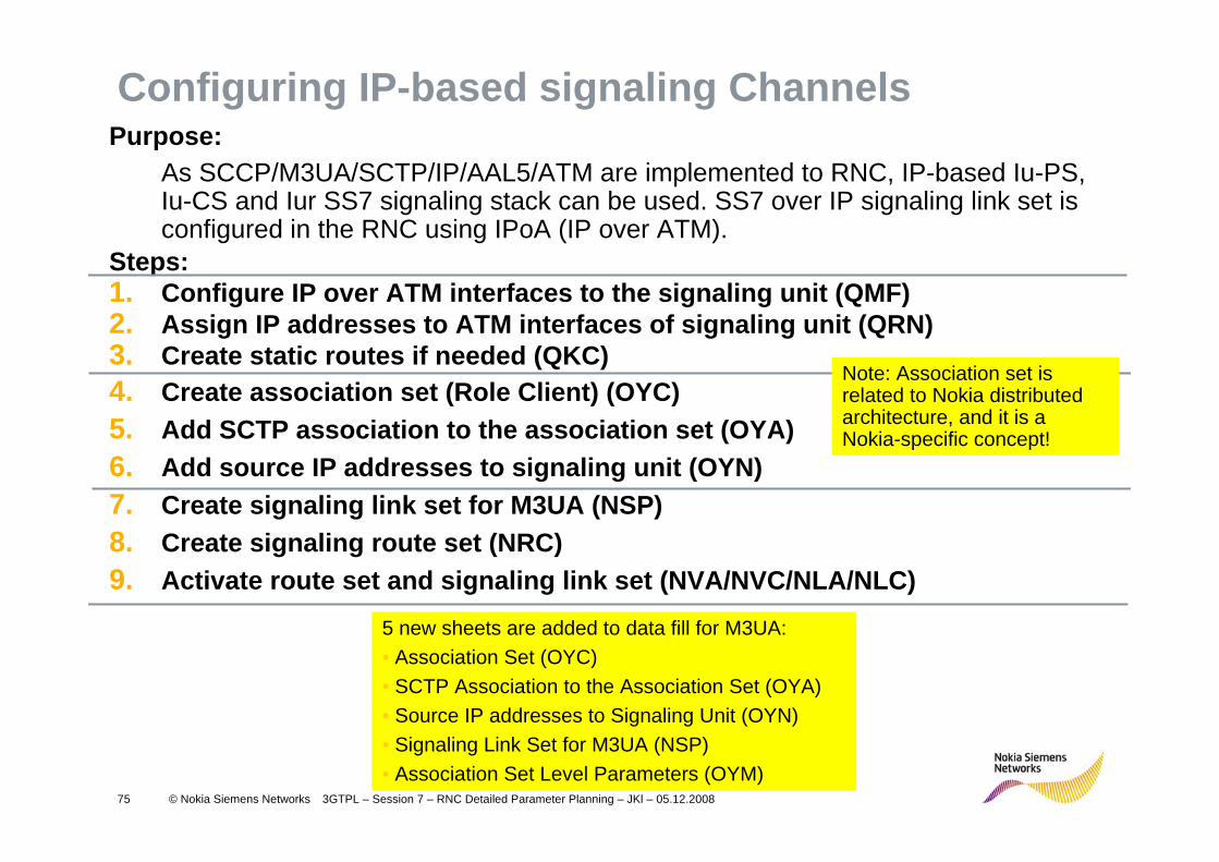
3GTPL – Session 7 – RNC Detailed Parameter Planning – JKl – 05.12.200875 © Nokia Siemens Networks
Configuring IP-based signaling ChannelsPurpose:
As SCCP/M3UA/SCTP/IP/AAL5/ATM are implemented to RNC, IP-based Iu-PS, Iu-CS and Iur SS7 signaling stack can be used. SS7 over IP signaling link set is configured in the RNC using IPoA (IP over ATM).
Steps:1. Configure IP over ATM interfaces to the signaling unit (QMF) 2. Assign IP addresses to ATM interfaces of signaling unit (QRN)3. Create static routes if needed (QKC)4. Create association set (Role Client) (OYC) 5. Add SCTP association to the association set (OYA) 6. Add source IP addresses to signaling unit (OYN) 7. Create signaling link set for M3UA (NSP)8. Create signaling route set (NRC)9. Activate route set and signaling link set (NVA/NVC/NLA/NLC)
5 new sheets are added to data fill for M3UA:• Association Set (OYC)• SCTP Association to the Association Set (OYA)• Source IP addresses to Signaling Unit (OYN)• Signaling Link Set for M3UA (NSP)• Association Set Level Parameters (OYM)
Note: Association set is related to Nokia distributed architecture, and it is a Nokia-specific concept!

3GTPL – Session 7 – RNC Detailed Parameter Planning – JKl – 05.12.200876 © Nokia Siemens Networks
Configuring parameters for ATM Routing
Iub/RNC
Iur
Iu-CS
Iu-PS
Iu-BC
Iub/AXCPhysical Interfaces
PDH/IMA/SDHSynchronization ATM resources
Cross connections
IPoAM
Physical Interfaces
PDH/IMA/SDHPhyTTP ATM resources
ConnectionConfiguration
(COCO)IPoAM
Physical Interfaces
PDH/IMA/SDHPhyTTP
ATM resourcesVPltp/VCltp SS7 Signaling
Routing and Digit Analysis
Physical Interfaces
PDH/IMA/SDHPhyTTP
ATM resourcesVPltp/VCltp SS7 Signaling
Iu-CSParameters
In RNC
Routing and Digit Analysis
Physical Interfaces
PDH/IMA/SDHPhyTTP
ATM resourcesVPltp/VCltp SS7 Signaling
Iu-PSParameters
In RNCIPoAUD
Physical Interfaces
PDH/IMA/SDHPhyTTP
ATM resourcesVPltp/VCltp
Iu-BCParameters in
RNCIPoAUD

3GTPL – Session 7 – RNC Detailed Parameter Planning – JKl – 05.12.200877 © Nokia Siemens Networks
ATM AAL2 End Point Addressing (A2EA)
RNC02
MGW01 RNC014903068001*
490023101*
45358112222233333*
490013100*BS4
WAM
AXC
VCC for AAL2 UD
Note : *) remaining digits (until 40) to be filled with HEX F
VPI1
VPI2
VPI1
VCI 40
VCI 120
VCI 40
VCI 120
VCI 45
Nodal Function
After configuring the physical and logical connections and the accordant signaling channels the system still doesn‘t know how and where to route the AAL2 traffic. For this we need AAL2 end addresses (A2EA) and a some sets of parameters. The algorithm used for finding the destination and allocating free resources is called Digit Analysis Tree (DA Tree)
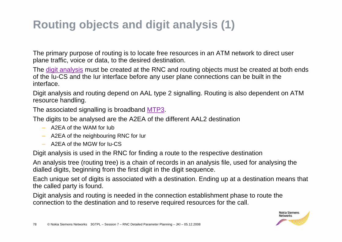
3GTPL – Session 7 – RNC Detailed Parameter Planning – JKl – 05.12.200878 © Nokia Siemens Networks
Routing objects and digit analysis (1)
The primary purpose of routing is to locate free resources in an ATM network to direct user plane traffic, voice or data, to the desired destination.The digit analysis must be created at the RNC and routing objects must be created at both ends of the Iu-CS and the Iur interface before any user plane connections can be built in theinterface. Digit analysis and routing depend on AAL type 2 signalling. Routing is also dependent on ATM resource handling.The associated signalling is broadband MTP3.The digits to be analysed are the A2EA of the different AAL2 destination
– A2EA of the WAM for Iub– A2EA of the neighbouring RNC for Iur– A2EA of the MGW for Iu-CS
Digit analysis is used in the RNC for finding a route to the respective destinationAn analysis tree (routing tree) is a chain of records in an analysis file, used for analysing the dialled digits, beginning from the first digit in the digit sequence.Each unique set of digits is associated with a destination. Ending up at a destination means that the called party is found.Digit analysis and routing is needed in the connection establishment phase to route the connection to the destination and to reserve required resources for the call.

3GTPL – Session 7 – RNC Detailed Parameter Planning – JKl – 05.12.200879 © Nokia Siemens Networks
Routing objects and digit analysis (2)
• Digit analysis gets the address of the other network element and finds the route for the destination by analysing the address.
• Routing also takes care of selecting the resources for the connections to offer desired properties for the connection, for example, by using Quality of Service (QoS).
• With these functions the traffic of connections can be divided between the different routes so that the resources in the network are used efficiently and blocking can be avoided.
• Digit analysis is available in the RNC, where AAL2 level is used for ATM routing. – A suitable Virtual Channel Connection (VCC) candidate under a given AAL type 2 route having free
resources and providing desired properties for the connection needs to be found for routing. – An AAL type 2 connection can be established under this selected VCC.
• Digit analysis determines the destination of a call and selects an AAL type 2 route to the destination. It analyses the digit sequences that it receives. Typically the received sequence is the address of the receiving end (E.164 number, AESA address), but digit analysis may be used to analyse any number sequence that can be analysed hierarchically digit by digit. Digit analysis is capable of analysing addresses up to 40 digits long. In ATM network, digit analysis is used in the Iub, Iur and Iu interfaces.
• Digit analysis and routing are closely connected to each other. Their relationship and objects used in routing and analysis in the RNC are illustrated in the following figure. The figure also shows the order and flow of the routing and analysis functions in call set-up phase.

3GTPL – Session 7 – RNC Detailed Parameter Planning – JKl – 05.12.200880 © Nokia Siemens Networks
AAL2 Address Format
• Nokia RNC supports the utilisation of the Local format as RNC own A2EA address.In some multi-vendor network, RNC own A2EA address should in Embedded E.164 format because some MGW does not recognise the Local format.
• For the remote A2EA address any of the four formats can be used• How to enter the A2EA, how to conclude the string (of 40 digits) and how many
digits are recognized by the systems, please see details in NED.• Note: What we call A2EA in RAN is AESA in the ATM world
Hexa Bits39 0011 100147 0100 011145 0100 010149 0100 1001
Embedded E.164 Local
AFIFormat
Data Country Code (DCC)International Code Designator (ICD)
AFI: Authority and Format IdentifierHO-DSP: High Order – Domain Specific Part.IDP: Initial Domain PartIDI: Initial Domain IdentifierESI: End System IdentifierSEL: Selector
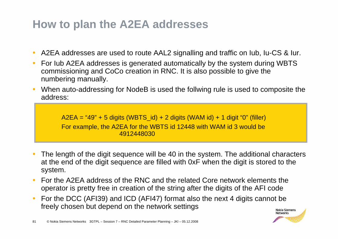
3GTPL – Session 7 – RNC Detailed Parameter Planning – JKl – 05.12.200881 © Nokia Siemens Networks
How to plan the A2EA addresses
• A2EA addresses are used to route AAL2 signalling and traffic on Iub, Iu-CS & Iur.• For Iub A2EA addresses is generated automatically by the system during WBTS
commissioning and CoCo creation in RNC. It is also possible to give the numbering manually.
• When auto-addressing for NodeB is used the follwing rule is used to composite the address:
A2EA = “49” + 5 digits (WBTS_id) + 2 digits (WAM id) + 1 digit “0” (filler)For example, the A2EA for the WBTS id 12448 with WAM id 3 would be
4912448030
• The length of the digit sequence will be 40 in the system. The additional characters at the end of the digit sequence are filled with 0xF when the digit is stored to the system.
• For the A2EA address of the RNC and the related Core network elements the operator is pretty free in creation of the string after the digits of the AFI code
• For the DCC (AFI39) and ICD (AFI47) format also the next 4 digits cannot be freely chosen but depend on the network settings

3GTPL – Session 7 – RNC Detailed Parameter Planning – JKl – 05.12.200882 © Nokia Siemens Networks
Digit Analysis and Routing in the RNC
ATM Route
ATM EndPoints Group ATM EndPoints Group
ATM End Point-VCC ATM End Point-VCC ATM End Point-VCC ATM End Point-VCC
VCC AAL2 connections
DigitAnalysis
Destination
A2EAAnalysis
Tree

3GTPL – Session 7 – RNC Detailed Parameter Planning – JKl – 05.12.200883 © Nokia Siemens Networks
Digit Analysis and Routing in the RNC
ATM Route
ATM EndPoints Group ATM EndPoints Group
ATM EndPoint-VCC ATM EndPoint-VCC ATM EndPoint-VCC ATM EndPoint-VCC
VCC AAL2 connections
DigitAnalysis
Destination
A2EAAnalysis
Tree
Digit Analysis Parameters Command: RDCParameters Digits Tree Route Number REMARKS
Data formatNUMERIC (string of digits) NUMERIC NUMERIC INFO
Value Range A2EA 1, 2, 3 1..4095
Default Value1 for Iub, 2 for Iur,
3 for Iu4544113584900110 3 100 Iu-CS to MGW
4905292101001 2 1001 Iur BLN014905292107001 2 1007 Iur BLN074905292109001 2 1009 Iur BLN094905292111001 2 1011 Iur BLN114905292141001 2 1014 Iur BLN14
Iub analysis trees created automatically with CoCo Objects => 1 Entry per NodeB in RNC database
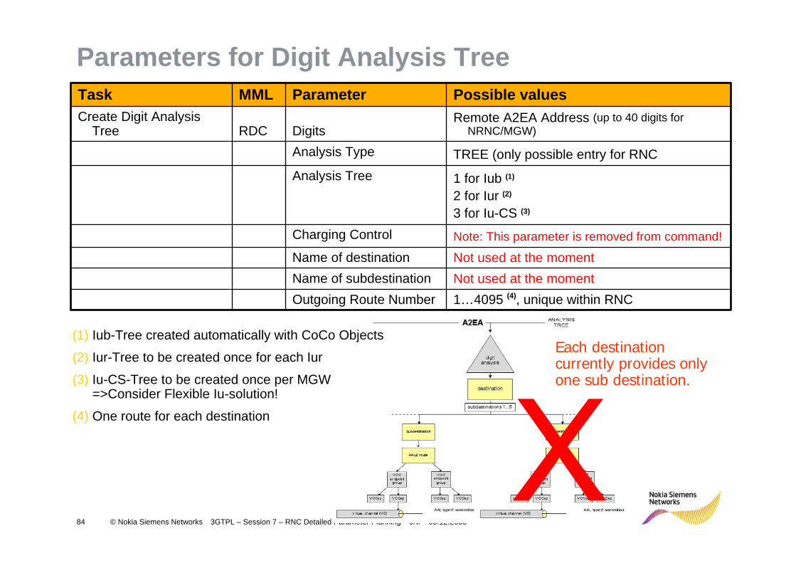
3GTPL – Session 7 – RNC Detailed Parameter Planning – JKl – 05.12.200884 © Nokia Siemens Networks
Parameters for Digit Analysis Tree
RDC
MMLCreate Digit Analysis
Tree
Task
TREE (only possible entry for RNCAnalysis Type
1…4095 (4), unique within RNCOutgoing Route NumberNot used at the momentName of subdestinationNot used at the momentName of destinationNote: This parameter is removed from command!Charging Control
1 for Iub (1)
2 for Iur (2)
3 for Iu-CS (3)
Analysis Tree
Remote A2EA Address (up to 40 digits for NRNC/MGW)Digits
Possible valuesParameter
Each destination currently provides only one sub destination.
(1) Iub-Tree created automatically with CoCo Objects
(2) Iur-Tree to be created once for each Iur
(3) Iu-CS-Tree to be created once per MGW =>Consider Flexible Iu-solution!
(4) One route for each destination

3GTPL – Session 7 – RNC Detailed Parameter Planning – JKl – 05.12.200885 © Nokia Siemens Networks
Digit Analysis and Routing in the RNC
ATM Route
ATM EndPoints Group ATM EndPoints Group
ATM EndPoint-VCC ATM EndPoint-VCC ATM EndPoint-VCC ATM EndPoint-VCC
VCC AAL2 connections
DigitAnalysis
Destination
A2EAAnalysis
Tree
ATM Routes Parameters for Iur Commands: RRC
ParametersRoute
NumberRoute Type Protocol Type
Signalling Network, not for Iub
Signalling Point Code, not for Iub AAL 2 Node Identifier REMARKS
Data format NUMERIC MNEMONIC MNEMONIC NUMERIC or HEXADECIMAL STRING INFO
Value Range 1...4095 AAL2, AAL5 UNI, MTP3 NA0, NA1, IN0, IN1 1...10 Chars
Default ValueFirst free
value100 AAL2 MTP3 NA0 2D82 ANMGW01 Iu-CS1001 AAL2 MTP3 NA0 2A44 ANRNCBLN01 Iur1007 AAL2 MTP3 NA0 2A39 ANRNCBLN07 Iur1009 AAL2 MTP3 NA0 2A0A ANRNCBLN09 Iur
1011 AAL2 MTP3 NA0 2A12 ANRNCBLN11 Iur
1014 AAL2 MTP3 NA0 2AA1 ANRNCBLN14 Iur

3GTPL – Session 7 – RNC Detailed Parameter Planning – JKl – 05.12.200886 © Nokia Siemens Networks
Parameters for ATM External Route
RRC
MML
Create ATM External Routes
Task
AAL2 / IP Route Type (2)
1…10 charactersAdjacent AAL2 Node Identifier (ANI) (6)
…of destinationSignalling Point Code (5)
NA0/NA1/IN0/IN1Signalling network used (4)
UNI / MTP3Protocol Type (3)
1…4095Route Number (1)
Possible valuesParameter
(1) Must be unique within the RNC(2) Currently the Route Type is AAL2(3) For Iu-CS and Iur it is MTP3 (not used if the route type is IP)(4) Not used if the route type is IP or the protocol used is UNI(5) Not used if the route type is IP or the protocol used is UNI. Defines the SS7 signalling
point code of the partner exchange(6) Not used if the route type is IP, defines identifier for the AAL2 node where the route is
leading to

3GTPL – Session 7 – RNC Detailed Parameter Planning – JKl – 05.12.200887 © Nokia Siemens Networks
Creating End Point Groups and End Points
ATM Route
ATM EndPoints Group ATM EndPoints Group
ATM EndPoint-VCC ATM EndPoint-VCC ATM EndPoint-VCC ATM EndPoint-VCC
VCC AAL2 connections
DigitAnalysis
Destination
ATM End Point Command: LIC Command:LJC
ParametersRoute
NumberEnd Point
Group Index
Ingress Service
Category
Egress Service Category
Connection ID (AAL2 path id)
ATM Interface ID
Virtual Path
Identifier (VPI)
Virtual Channel Identifier
(VCI)
Ownership Loss Ratio MUX Delay
Signalling Link
Interface Id(only on Iub)
Signalling Link VPI(only on
Iub)
Signalling Link VCI(only on
Iub)
REMARKS
Data format NUMERIC NUMERIC MNEMONIC MNEMONIC NUMERIC NUMERIC NUMERIC NUMERIC MNEMONIC NUMERIC NUMERIC NUMERIC NUMERIC NUMERIC INFO
Value Range 0 ... 4095 0….15 C/RV/NV C/RV/NV1 ...
4 294 967 2961..320 0 ... 255 1 ... 65535
LOCAL, PEER
9 ... 3 10 ... 100 1...320 0...255 1...65535
Default 4 50100 1 C C 100 1 10401 200 0 40 LOCAL 5 100 Iu-CS100 1 10402 200 0 41 LOCAL 5 100 Iu-CS
100 1 10419 200 0 58 LOCAL 5 100 Iu-CS100 1 10420 200 0 59 LOCAL 5 100 Iu-CS1001 1 C C1001 1 11041 202 0 50 PEER 5 100 Iur041007 1 C C1007 1 11071 202 1 50 PEER 5 100 Iur071009 1 C C1009 1 11091 202 2 50 PEER 5 100 Iur091009 1 11092 202 2 21 PEER 5 100 Iur091011 1 C C1011 1 11111 203 0 50 LOCAL 5 100 Iur111011 1 11112 203 0 51 LOCAL 5 100 Iur111014 1 C C1014 1 11141 204 0 50 PEER 5 100 Iur141014 1 11142 204 0 51 PEER 5 100 Iur14

3GTPL – Session 7 – RNC Detailed Parameter Planning – JKl – 05.12.200888 © Nokia Siemens Networks
Parameters for ATM End Points and End Point Groups
LJC
LIC
MML
Create End Points
Create End Point Group
Task
9...3Loss Ratio (7)
1…320Interface ID (5)
Local / peerOwnership(6)
Previously definedVPI / VCI (5)
10..100 ( 0.1 msec multiples)MUX Delay (8)
0…15End Point Group Index (2)
1...4 294 967 296AAL2 Type Path Identifier (PID) (4)
C: Constant Bit RateRV: Real Time - Variable Bit Rate (3)
NV: Non Real Time - Variable Bit Rate (3)
Service Category
1…65536 (4095)Route Number (1)
Possible valuesParameter
(1) The route under which the endpoint group is created. The parameter value is a decimal number(2) The endpoint group uniquely under the route. If not given, value is automatically selected by the system.(3) Not supported(4) A numerical value uniquely identifying the ATM VCC between two AAL type 2 nodes(5) Depends on previous planning (6) For CID assignment, the remote end must have opposite setting(7) The resulting loss ratios are between 10–9 and 10–3
(8) Multiples of 100µs

3GTPL – Session 7 – RNC Detailed Parameter Planning – JKl – 05.12.200889 © Nokia Siemens Networks
What is needed to create Routing objects and digit analysis• Ensure that all needed ATM resources and cross connections
are correctly created (AAL2UD and MTP3SL VCCs), and that the SS7 signaling network is correctly configured.
• For Iur, each RNC is identified with its A2EA address• On the Iu-CS, the MGW is identified with its A2EA address• For Iub each WAM is identified with its A2EA address
(automatically created with CoCo Objects)• The following routing objects should be created:
– Digit Analysis Tree– AAL type 2 route– AAL2 endpoint– AAL2 endpoint group

3GTPL – Session 7 – RNC Detailed Parameter Planning – JKl – 05.12.200890 © Nokia Siemens Networks
New Feature: Flexible Iu
L
MGW MGW
MEGACO/ H.248
ATM/IP/TDM
MSS/VLR
RNCRNCRNCRNC
Double Iu-CS interface for each RNC
With RAS06 there‘s a new feature named Flexible Iu. It is possible to connect each RNC to two different MGW. This is simply for redundancy to protect from
• outage of any Iu-CS interface
• failure on a MEGACO connection
• outage of the MGW itself
The interfaces and the MGW have to be planned and dimensioned accordingly.

3GTPL – Session 7 – RNC Detailed Parameter Planning – JKl – 05.12.200891 © Nokia Siemens Networks
Configuring parameters for Iu-PS interface
Iub/RNC
Iur
Iu-CS
Iu-PS
Iu-BC
Iub/AXCPhysical Interfaces
PDH/IMA/SDHSynchronization ATM resources
Cross connections
IPoAM
Physical Interfaces
PDH/IMA/SDHPhyTTP ATM resources
ConnectionConfiguration
(COCO)IPoAM
Physical Interfaces
PDH/IMA/SDHPhyTTP
ATM resourcesVPltp/VCltp SS7 Signaling
Routing and Digit Analysis
Physical Interfaces
PDH/IMA/SDHPhyTTP
ATM resourcesVPltp/VCltp SS7 Signaling
Iu-CSParameters
In RNC
Routing and Digit Analysis
Physical Interfaces
PDH/IMA/SDHPhyTTP
ATM resourcesVPltp/VCltp SS7 Signaling
Iu-PSParameters
In RNCIPoAUD
Physical Interfaces
PDH/IMA/SDHPhyTTP
ATM resourcesVPltp/VCltp
Iu-BCParameters in
RNCIPoAUD

3GTPL – Session 7 – RNC Detailed Parameter Planning – JKl – 05.12.200892 © Nokia Siemens Networks
Iu-PS connections• On the Iu-PS, the ATM VCC are terminated in the GTPU on the RNC side and on the GPLC
on the 3G SGSN side.• Each GTPU can be connected to more than one GPLC in the SGSN (in case B)• Iu-PS traffic routing can be based on “static routing” or “OSPF”, the choice of either/or of the
methods depends on the Packet core plans on the network
Case A (outdated) Case B (not used when OSPF is implemented)
CRP
CRP: Central Routing Processor (SGSN)GPLC: General Purpose Line Card (SGSN)
10.1.1.11 10.2.0.1
10.1.2.11 10.3.0.1
10.1.1.13 10.2.0.1
10.1.2.13 10.3.0.1
AA0
AA0
AA0
AA0
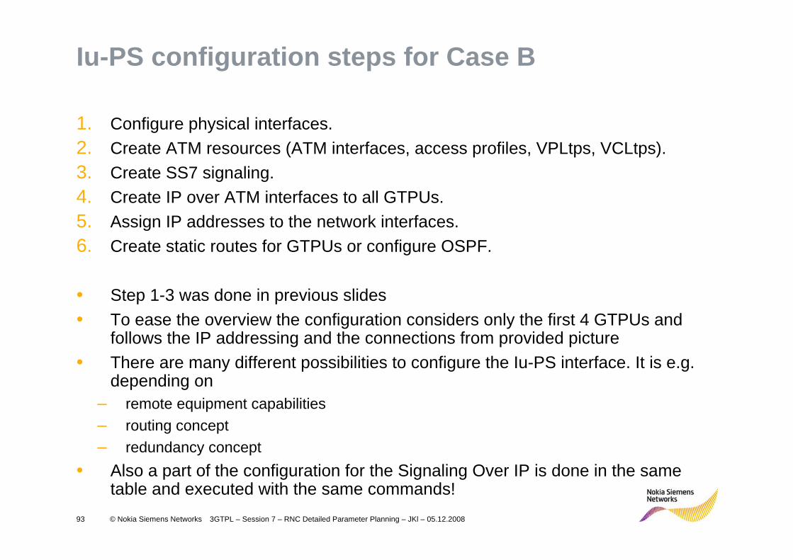
3GTPL – Session 7 – RNC Detailed Parameter Planning – JKl – 05.12.200893 © Nokia Siemens Networks
Iu-PS configuration steps for Case B
1. Configure physical interfaces.2. Create ATM resources (ATM interfaces, access profiles, VPLtps, VCLtps).3. Create SS7 signaling.4. Create IP over ATM interfaces to all GTPUs.5. Assign IP addresses to the network interfaces.6. Create static routes for GTPUs or configure OSPF.
• Step 1-3 was done in previous slides• To ease the overview the configuration considers only the first 4 GTPUs and
follows the IP addressing and the connections from provided picture• There are many different possibilities to configure the Iu-PS interface. It is e.g.
depending on – remote equipment capabilities– routing concept– redundancy concept
• Also a part of the configuration for the Signaling Over IP is done in the same table and executed with the same commands!

3GTPL – Session 7 – RNC Detailed Parameter Planning – JKl – 05.12.200894 © Nokia Siemens Networks
Creating TCP/IP ATM Interfaces for Iu-PS User Plane
4. Create IP over ATM interfaces to all GTPUs.
CRP
10.1.1.11 10.2.0.1
10.1.2.11 10.3.0.1
10.1.1.13 10.2.0.1
10.1.2.13 10.3.0.1
TCP/ IP ATM Interface Commands: QMF
ParametersUnit Type Unit Index IP Address Type
Network Interface
ATM Interface VPI VCIEncapsulation
MethodUsage REMARKS
Data format MNEMONIC NUMERIC MNEMONIC NUMERIC NUMERIC NUMERIC NUMERIC MNEMONIC MNEMONIC INFO
Value RangeGTPU, OMU,
ICSU0, 1, - for OMU,0, ... for GTPU L,P AA0 ... AA511 1..588
0 ... 255 UNI,0 ... 4095 NNI 1 ... 65535
1 (LLC/SNAP)/ 2 (VCmux)
IPOAM, IPOAUD,IPOART
GTPU 0 P AA0 1 0 40 1 IPOAUDGTPU 0 P AA1 1 0 41 1 IPOAUDGTPU 1 P AA0 1 0 42 1 IPOAUDGTPU 1 P AA1 1 0 43 1 IPOAUDGTPU 2 P AA0 2 0 40 1 IPOAUDGTPU 2 P AA1 2 0 41 1 IPOAUDGTPU 3 P AA0 2 0 42 1 IPOAUDGTPU 3 P AA1 2 0 43 1 IPOAUD
ICSU 1 L AA10 200 1 151 1 IPOAMICSU 1 L AA11 200 1 152 1 IPOAMICSU 2 L AA20 200 1 153 1 IPOAMICSU 2 L AA21 200 1 154 1 IPOAM
OMU - L AA100 1 84 32 1 IPOAMOMU - L AA101 1 25 32 1 IPOAMOMU - L AA102 1 69 32 1 IPOAMOMU - L AA103 1 121 32 1 IPOAM
Example for Iu-PS
Example for Sig over IP
Example for O&M to NodeB

3GTPL – Session 7 – RNC Detailed Parameter Planning – JKl – 05.12.200895 © Nokia Siemens Networks
Required parameters TCP/IP ATM Interfaces forIu-PS UP & SIGNALLING
The value can be IPOAUD, IPOART or IPOAM.Usage
Possible valuesParameterMMLTask
LLC/SNAP or VCmux. The default value is LLC/SNAP (Setting “1”).Encapsulation method
IF / VPI / VCI => from previous planningATM interface
It’s a unique name for the IP over ATM interface. It begins with 'AA' and continues with numbers
Network interface
Logical or Physical (L/P), This parameter defines whether IP over ATM interface is terminated to the logical or physical address type of the unit. The possible parameter values are L for logical address type and P for physical address type.For the GTPU the interface is (P)For the ICSU the interface is (L)For the OMU the interface is (L)
IP address type
GTPU for Iu-PS and their respective index (unit number)ICSU when Sig over IP is usedOMU for O&M connections
unit type/ IndexQMFCreating TCP/IP ATM Interfaces
Note: For detailed parameter explanations please refer to NED!

3GTPL – Session 7 – RNC Detailed Parameter Planning – JKl – 05.12.200896 © Nokia Siemens Networks
Creating TCP/IP Network Interfaces for Iu-PS User Plane
CRP
10.1.1.11 10.2.0.1
10.1.2.11 10.3.0.1
10.1.1.13 10.2.0.1
10.1.2.13 10.3.0.1
5. Assign IP addresses to the network interfaces.
TCP/IP Network Interface Commands: QRN
Parameters
Unit Type Unit IndexNetwork
Interface Name
Numbered / Unnumberd
Interface
IP Address, only for numbered interfaces
IP Address for Loopback
IP Address Type
Netmask Length, only for
numbered interfaces
Destination IP Address (only for AAx interfaces)
Destination IP for Loopback
Maximum Transmission Unit (MTU), only for AA interfaces, optional
State of Interface
REMARKS
Data format MNEMONIC NUMERIC STRING MNEMONIC MNEMONIC MNEMONIC MNEMONIC NUMERIC NUMERIC NUMERIC NUMERIC MNEMONIC INFO
Value RangeGTPU, OMU,
ICSU ...0, 1, - for OMU,0, ... for GTPU
AA<name>,EL<name>,LO<name>;
U, N; U only for AA
interfacesn.n.n.n: 0.0.0.0 ... 255.255.255.255
0.0.0.0 ... 255.255.255.
255 L, P 4 ... 32n.n.n.n : 0.0.0.0 ... 255.255.255.255
0.0.0.0 ... 255.255.255.2
55 1...65535, optional UP / DOWNGTPU 0 AA0 N 10.1.1.10 P 32 10.2.0.1 2400 UPGTPU 0 AA1 N 10.1.2.10 P 32 10.3.0.1 2400 UPGTPU 1 AA0 N 10.1.1.11 P 32 10.2.0.1 2400 UPGTPU 1 AA1 N 10.1.2.11 P 32 10.3.0.1 2400 UPGTPU 2 AA0 N 10.1.1.12 P 32 10.2.0.1 2400 UPGTPU 2 AA1 N 10.1.2.12 P 32 10.3.0.1 2400 UPGTPU 3 AA0 N 10.1.1.13 P 32 10.2.0.1 2400 UPGTPU 3 AA1 N 10.1.2.13 P 32 10.3.0.1 2400 UP
ICSU 1 AA10 N 172.16.12.17 L 30 172.16.12.18 1500 UPICSU 1 AA11 N 172.16.12.41 L 30 172.16.12.42 1500 UPICSU 2 AA20 N 172.16.12.21 L 30 172.16.12.22 1500 UPICSU 2 AA21 N 172.16.12.45 L 30 172.16.12.46 1500 UP
OMU - AA100 N 172.16.13.62 L 28 172.16.13.61 1500 UPOMU - AA101 N 172.16.13.126 L 28 172.16.13.125 1500 UPOMU - AA102 N 172.16.13.158 L 28 172.16.13.157 1500 UPOMU - AA103 N 172.16.14.46 L 28 172.16.14.45 1500 UP
Example for Iu-PS
Example for Sig over IP
Example for O&M to NodeB
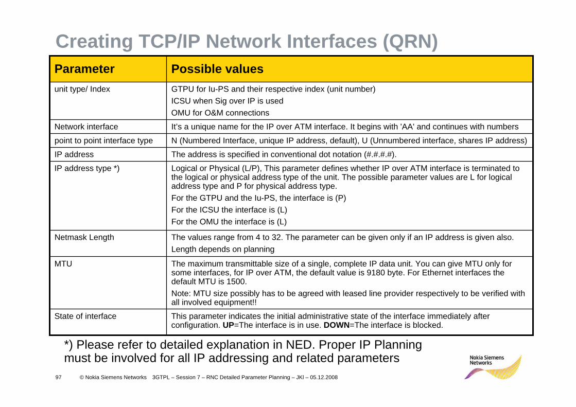
3GTPL – Session 7 – RNC Detailed Parameter Planning – JKl – 05.12.200897 © Nokia Siemens Networks
Creating TCP/IP Network Interfaces (QRN)
The maximum transmittable size of a single, complete IP data unit. You can give MTU only for some interfaces, for IP over ATM, the default value is 9180 byte. For Ethernet interfaces the default MTU is 1500.Note: MTU size possibly has to be agreed with leased line provider respectively to be verified with all involved equipment!!
MTU
This parameter indicates the initial administrative state of the interface immediately after configuration. UP=The interface is in use. DOWN=The interface is blocked.
State of interface
The values range from 4 to 32. The parameter can be given only if an IP address is given also.Length depends on planning
Netmask Length
Logical or Physical (L/P), This parameter defines whether IP over ATM interface is terminated to the logical or physical address type of the unit. The possible parameter values are L for logical address type and P for physical address type.For the GTPU and the Iu-PS, the interface is (P)For the ICSU the interface is (L)For the OMU the interface is (L)
IP address type *)
The address is specified in conventional dot notation (#.#.#.#).IP address
N (Numbered Interface, unique IP address, default), U (Unnumbered interface, shares IP address) point to point interface type
It’s a unique name for the IP over ATM interface. It begins with 'AA' and continues with numbersNetwork interface
GTPU for Iu-PS and their respective index (unit number)ICSU when Sig over IP is usedOMU for O&M connections
unit type/ Index
Possible valuesParameter
*) Please refer to detailed explanation in NED. Proper IP Planning must be involved for all IP addressing and related parameters
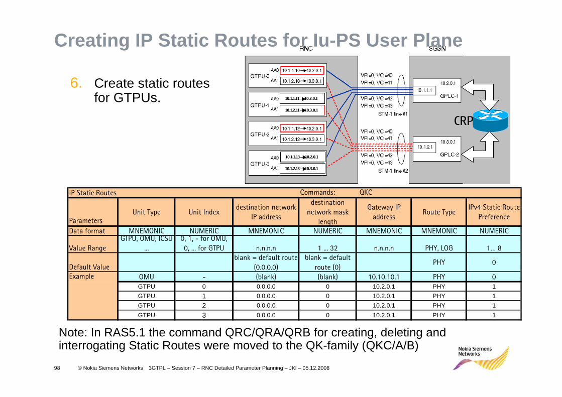
3GTPL – Session 7 – RNC Detailed Parameter Planning – JKl – 05.12.200898 © Nokia Siemens Networks
CRP
10.1.1.11 10.2.0.1
10.1.2.11 10.3.0.1
10.1.1.13 10.2.0.1
10.1.2.13 10.3.0.1
Creating IP Static Routes for Iu-PS User Plane
6. Create static routes for GTPUs.
IP Static Routes Commands: QKC
ParametersUnit Type Unit Index
destination network IP address
destination network mask
length
Gateway IP address
Route TypeIPv4 Static Route
Preference
Data format MNEMONIC NUMERIC MNEMONIC NUMERIC MNEMONIC MNEMONIC NUMERIC
Value RangeGTPU, OMU, ICSU
...0, 1, - for OMU,0, ... for GTPU n.n.n.n 1 ... 32 n.n.n.n PHY, LOG 1… 8
Default Valueblank = default route
(0.0.0.0)blank = default
route (0)PHY 0
Example OMU - (blank) (blank) 10.10.10.1 PHY 0GTPU 0 0.0.0.0 0 10.2.0.1 PHY 1GTPU 1 0.0.0.0 0 10.2.0.1 PHY 1GTPU 2 0.0.0.0 0 10.2.0.1 PHY 1GTPU 3 0.0.0.0 0 10.2.0.1 PHY 1
Note: In RAS5.1 the command QRC/QRA/QRB for creating, deleting and interrogating Static Routes were moved to the QK-family (QKC/A/B)

3GTPL – Session 7 – RNC Detailed Parameter Planning – JKl – 05.12.200899 © Nokia Siemens Networks
Creating IP Static Routes for Iu-PS User Plane
• The routing of IP packets on Iu-PS is based on Static Routing Tables, and Inverse ATM ARP (InvATMARP) tables.
• When the ATM VCCs are connected between the RNC and the SGSN, the RNC enquires what IP address is at the other end of each VCC. When it receives this enquiry, the SGSN responds with the Interface address of the GPLC to which that VCC is connected. Now the RNC knows on which VCCs to send user data IP packets on the uplink.
For the GTPU this is the IP address of the GPLC interface (or loopback interface) to which the VCC is connected. This parameter is obligatory
Gateway IP Address
The route type for the static route to be created. It is not available for multiple default route configuration.PHY: A route that uses a physical address to reach its gateway. A physical route is always present in the unit it is configured. This is the default value.LOG: A route that uses a logical address to reach its gateway. The route follows the logical address if a switchover occurs.
Route Type
The length of the destination address net mask. This parameter indicates which units are to be included on the route.
Destination network mask length
GTPU for Iu-PS and their respective index (unit number)ICSU when Sig over IP is used (also for Iu-BC)OMU for O&M connections
unit type/ Index
The route's destination IP address or IP sub network. If you want to define the default route (0.0.0.0) or to create a multiple default route, do not enter this parameter.
Destination IP address
Currently no preferences. All entries should be on same numberIPv4 Static Route Preference
Possible valuesParameter

3GTPL – Session 7 – RNC Detailed Parameter Planning – JKl – 05.12.2008100 © Nokia Siemens Networks
Case C: OSPF on Iu-PS - Required parameters Note: The following material is considered as additional information and is not subject of this training anymore as it requires deep knowledge of IP-Planning and Routing Protocols
This example shows how to configure the Iu-PS interface between the RNC and SGSN using OSPF (Open Shortest Path First) for routing. When OSPF is in use and a link fails, the user plane traffic is automatically switched to the working link.
CRP

3GTPL – Session 7 – RNC Detailed Parameter Planning – JKl – 05.12.2008101 © Nokia Siemens Networks
Iu-PS configuration steps (OSPF case)
• Configure physical interfaces.• Create ATM resources (ATM interfaces, access profiles,
VPLtps, VCLtps).• Create SS7 signalling.• Create IP over ATM interfaces to all GTPUs.• Assign IP addresses to the network interfaces.• Configure OSPF
A. Set the loopback IP address for each GTPU unit.B. Configure the area(s)C. Configure the OSPF to inform other OSPF routers of the loopback
address.D. Configure interfaces for that area.

3GTPL – Session 7 – RNC Detailed Parameter Planning – JKl – 05.12.2008102 © Nokia Siemens Networks
CRP
Required parameters for OSPF on Iu-PS
TCP/IP Network Interface Command QRN
Unit Type Unit IndexInterface
NameInterface
TypeIP Address
IP Address Type
Netmask Length
Destination IP Address
Maximum Transmission Unit (MTU)
REMARKS ACTION
MNEMONIC NUMERIC S TRING MNEMONIC NUMERIC MNEMONIC NUMERIC NUMERIC NUMERIC INFO INFO
0..5
3 ..6 c ha rs s ta rts with AA/EL/LO N/U # .# .# .# L/P 4 …30 #.# .# .# 1…655 35
GTPU 0 LO0 N 10.1.1.2 P 32 - 1500 loopbackGTPU 1 LO0 N 10.1.1.3 P 32 - 1500 loopbackGTPU 2 LO0 N 10.1.1.4 P 32 - 1500 loopbackGTPU 3 LO0 N 10.1.1.5 P 32 - 1500 loopback
A. Set the loopback IP address for each GTPU unit.

3GTPL – Session 7 – RNC Detailed Parameter Planning – JKl – 05.12.2008103 © Nokia Siemens Networks
CRP
Required parameters for OSPF on Iu-PS
IP OSPF Areas Commands: QKE
Unit Type Unit Index Area Identification
Stub Area Stub Area Route Cost
Totally Stubby Area
REMARKS ACTION
MNEMONIC NUMERIC NUMERIC MNEMONIC NUMERIC MNEMONIC INFO INFO
OMU/NIS /GTP U/ICS U #.# .# .# Y/N Y/N
GTPU 0 0.0.0.1 Y 0 Y
GTPU 1 0.0.0.1 Y 0 Y
GTPU 2 0.0.0.1 Y 0 Y
GTPU 3 0.0.0.1 Y 0 Y
B. Configure the area(s)
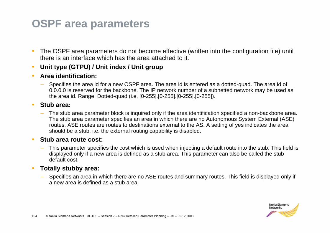
3GTPL – Session 7 – RNC Detailed Parameter Planning – JKl – 05.12.2008104 © Nokia Siemens Networks
OSPF area parameters
• The OSPF area parameters do not become effective (written into the configuration file) until there is an interface which has the area attached to it.
• Unit type (GTPU) / Unit index / Unit group• Area identification:
– Specifies the area id for a new OSPF area. The area id is entered as a dotted-quad. The area id of 0.0.0.0 is reserved for the backbone. The IP network number of a subnetted network may be used as the area id. Range: Dotted-quad (i.e. [0-255].[0-255].[0-255].[0-255]).
• Stub area:– The stub area parameter block is inquired only if the area identification specified a non-backbone area.
The stub area parameter specifies an area in which there are no Autonomous System External (ASE) routes. ASE routes are routes to destinations external to the AS. A setting of yes indicates the area should be a stub, i.e. the external routing capability is disabled.
• Stub area route cost:– This parameter specifies the cost which is used when injecting a default route into the stub. This field is
displayed only if a new area is defined as a stub area. This parameter can also be called the stub default cost.
• Totally stubby area:– Specifies an area in which there are no ASE routes and summary routes. This field is displayed only if
a new area is defined as a stub area.

3GTPL – Session 7 – RNC Detailed Parameter Planning – JKl – 05.12.2008105 © Nokia Siemens Networks
CRP
Required parameters for OSPF on Iu-PS
IP OSPF Redistribute Parameters Commands: QKU
Unit Type Unit Index Redistribute Type
Identification (only if Redistribute is IF)
Metric REMARKS ACTION
MNEMONIC NUMERIC MNEMONIC MNEMONIC NUMERIC INFO INFO
OMU/NIS /GTP U/ICS U S T, IF EL0 , AA, LO
GTPU 0 IF LO0 1
GTPU 1 IF LO0 1
GTPU 2 IF LO0 1
GTPU 3 IF LO0 1
C. Configure the OSPF to inform other OSPF routers of the loopback address.

3GTPL – Session 7 – RNC Detailed Parameter Planning – JKl – 05.12.2008106 © Nokia Siemens Networks
OSPF redistribute parameters
Unit type: – The type of the computer unit in which you want to configure the OSPF
redistribution information. The program provides a list of units from which to choose. Parameter is mandatory.
Unit index: – The index of the computer unit in which you want to configure the
OSPF redistribution information. The index is given in decimal form. The number of units determines the maximum value of the parameter. Those unit types, which also require a unit group number in the unit identification, the unit index is only given after the parameter unit group. Parameter is mandatory.
Redistribute type and identification: – it is possible to redistribute an interface (IF) or a static route (ST).
Metric: – it is possible to associate a metric to the route redistributed.

3GTPL – Session 7 – RNC Detailed Parameter Planning – JKl – 05.12.2008107 © Nokia Siemens Networks
CRP
Required parameters for OSPF on Iu-PS
IP OSPF Interface Parameters Commands: QKF
Unit Type Unit Index Interface Identification
Area Identification
Hello Interval Router Dead Intervel
OSPF Cost Election Priority
Passive Authentication REMARKS ACTION
MNEMONIC NUMERIC S TRING NUMERIC NUMERIC NUMERIC NUMERIC NUMERIC MNEMONIC MNEMONIC INFO INFO
OMU/NIS /GTP U/ICS U 1...10 Cha rs # .# .# .# 1...655 35 1...655 35 Y/N
NONE/ S IMP LE/ MD 5
GTPU 0 AA0 0.0.0.1 10 40 1 - N NONEGTPU 1 AA0 0.0.0.1 10 40 1 - N NONEGTPU 2 AA0 0.0.0.1 10 40 1 - N NONEGTPU 3 AA0 0.0.0.1 10 40 1 - N NONEGTPU 0 AA1 0.0.0.1 10 40 1 - N NONEGTPU 1 AA1 0.0.0.1 10 40 1 - N NONEGTPU 2 AA1 0.0.0.1 10 40 1 - N NONEGTPU 3 AA1 0.0.0.1 10 40 1 - N NONE
D. Configure interfaces for that area.

3GTPL – Session 7 – RNC Detailed Parameter Planning – JKl – 05.12.2008108 © Nokia Siemens Networks
OSPF interface parameters (1)
• Unit type / Unit index / Unit group• Interface identification:
– The name of the interface is given as a character string, maximum 10 characters. The parameter is mandatory. The configured interfaces that can be used as an OSPF interface can be found with the QRA MML command.
• Area identification: – This parameter specifies the area id to which the interface will be attached. The
parameter is mandatory when configuring an OSFP interface. The area id is entered as a dotted-quad. The area id of 0.0.0.0 is reserved for the backbone. Range: Dotted-quad (i.e. [0-255].[0-255].[0-255].[0-255]).
• Hello interval: – This parameter specifies the length of time, in seconds, between hello packets that the
router sends on the interface. For a given link, this field must be the same on all routers or adjacencies will not form.
• Router dead interval: – This parameter specifies the number of seconds being unable to hear a router's hello
packets before the router declares the neighbour is down. Typically, the value of this field should be four times the size of the hello interval. For a given link, this field must be the same on all routers or adjacencies will not form.

3GTPL – Session 7 – RNC Detailed Parameter Planning – JKl – 05.12.2008109 © Nokia Siemens Networks
OSPF interface parameters (2)
• OSPF cost:– This parameter specifies the weight of a given path in a route. The higher the cost, the less preferred the link. You may
explicitly override this in route redistribution. For example: to use one interface over another for routing paths, give one a higher cost.
• Election priority:– This parameter specifies the priority for becoming the designated router (DR) on this link. When two routers attached to
a network both attempt to become a designated router, the one with the highest priority wins. If there is currently an elected DR on the link, it will remain the DR regardless of the configured priority. This is to prevent changing the DR too often. This field is only relevant on a shared-media interface (Ethernet), as a DR is not elected on point-to-point type interfaces. A router with priority 0 is not eligible to become the designated router.
• Passive:– An interface that is put into passive mode will not send hello packets out of the given interface. This means no
adjacencies will be formed on the link. The purpose of this mode is to enable the network associated with the interface to be included in the intra-area route calculation as opposed to redistributing the network into OSPF and having it as an ASE. In passive mode, all interface configuration information, with the exception of the associated area and the cost, are ignored.
Y: suppressed hello packets / N: do not suppress hello packets (default)
• Authentication:– This parameter indicates what type of authentication scheme to use for a given OSPF interface. In general, routers on a
given link must agree on the authentication configuration in order to form neighbour adjacencies. This is used to guarantee that routing information is accepted only from trusted routers.
NONE: no authentication is used (default) / SIMPLE: simple password authentication is used / MD5: MD5 authentication method is used
• Password:– If the authentication type was selected as SIMPLE or MD5, then a password is required. With SIMPLE the password is
an ascii string of the length 1-8 characters. With the MD5 the password size is 1-16 characters.
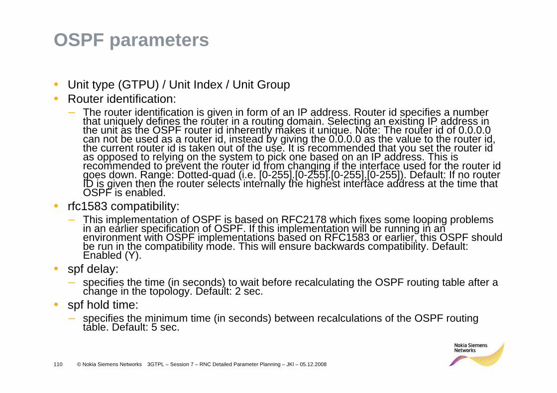
3GTPL – Session 7 – RNC Detailed Parameter Planning – JKl – 05.12.2008110 © Nokia Siemens Networks
OSPF parameters
• Unit type (GTPU) / Unit Index / Unit Group • Router identification:
– The router identification is given in form of an IP address. Router id specifies a number that uniquely defines the router in a routing domain. Selecting an existing IP address in the unit as the OSPF router id inherently makes it unique. Note: The router id of 0.0.0.0 can not be used as a router id, instead by giving the 0.0.0.0 as the value to the router id, the current router id is taken out of the use. It is recommended that you set the router id as opposed to relying on the system to pick one based on an IP address. This is recommended to prevent the router id from changing if the interface used for the router id goes down. Range: Dotted-quad (i.e. [0-255].[0-255].[0-255].[0-255]). Default: If no router ID is given then the router selects internally the highest interface address at the time that OSPF is enabled.
• rfc1583 compatibility: – This implementation of OSPF is based on RFC2178 which fixes some looping problems
in an earlier specification of OSPF. If this implementation will be running in an environment with OSPF implementations based on RFC1583 or earlier, this OSPF should be run in the compatibility mode. This will ensure backwards compatibility. Default: Enabled (Y).
• spf delay: – specifies the time (in seconds) to wait before recalculating the OSPF routing table after a
change in the topology. Default: 2 sec.• spf hold time:
– specifies the minimum time (in seconds) between recalculations of the OSPF routing table. Default: 5 sec.

3GTPL – Session 7 – RNC Detailed Parameter Planning – JKl – 05.12.2008111 © Nokia Siemens Networks
OSPF Virtual Link Parameters
• If the router is a border router with no interfaces in the backbone area, it must configure a virtual link connecting it to the backbone area. The virtual link is effectively a tunnel across an adjacent non-backbone area whose endpoint must be any of the adjacent area's border routers that has an interface in the backbone area. – Unit type / Unit index / Unit group– Router identification:
This parameter specifies the router id of the remote endpoint of the virtual link. Parameter is mandatory.
– Transit area:This parameter specifies the area shared by the border router on which we are configuring the virtual link, and the router with an interface in the backbone area. Traffic between the endpoints of the virtual link will flow through this area. The transit area can't be a backbone area or a stub area. Parameter is mandatory.
– Hello interval– Router dead interval– Authentication
Password

3GTPL – Session 7 – RNC Detailed Parameter Planning – JKl – 05.12.2008112 © Nokia Siemens Networks
OSPF network prefix parameters
• Unit type / Unit index / Unit group• Area identification• Network prefix:
– Any area can be configured with any number of address ranges. These ranges are used to potentially reduce the number of routing entries that a given area will emit into the backbone (and hence all) areas. If a given prefix aggregates a number of more specific prefixes within an area, then an address range can be configured and will be the only prefix advertised into the backbone. Care must be taken in configuring an address range that covers parts of a prefix that are not contained within the area.
• Network prefix mask length:– The mask length defines the mask length of the address range to be advertised.
• Network prefix restriction:– If an address range was marked restrict, then no advertisement will be injected
into the backbone. The default is yes. Y: summary LSA are advertised / N: no summary LSA are advertised

3GTPL – Session 7 – RNC Detailed Parameter Planning – JKl – 05.12.2008113 © Nokia Siemens Networks
Summary Iu-PS
• Since release RAN04 it does not automatically require the migration from Static Routes to OSPF
• Planning OSPF for Iu-PS requires a very good knowledge about IP networks and Routing Protocols
• Loopback for GPLC and GTPU provides most possible safety from traffic loss
• Since SGSN Release 3 also MSP1+1 is possible for Iu-PS– Little delay but no loss of PDP context in case line or interface black out