08. Quays and Slipways
26
107 8. Quays and slipways SUMMARY For the purpose of this chapter, a quay is a general term used to describe a marine structure for the mooring or tying-up of vessels, and for loading and unloading of goods and passengers. It is generally contiguous with the shore. A pier or finger jetty is a quay that projects into the water. In contrast to a normal quay, a finger jetty may be used on both sides. In areas with a high tidal range, both quays and jetties are often of the floating type. The traditional slipway in many small beach-side communities is still the natural beach where boats are hauled ashore for scrubbing, cleaning and repair. However, a beach is not always suitable or available for servicing a vessel, especially vessels larger than small canoes. On the other hand, inside fishing harbours, the recent technological advances in boat hoists has further widened the range of options available to a would-be designer of slipways. This chapter reviews the cross-sections of a wide variety of quays and jetties to suit an even wider range of applications. The objective being that the reader will be able to appreciate the different applications of past and more recent technologies and be better prepared to assess the potential requirements for berthing and boat maintenance structures.
-
Upload
cristian-gavrilescu -
Category
Documents
-
view
56 -
download
2
description
quays and slipways
Transcript of 08. Quays and Slipways
107
8. Quays and slipways
SUMMARY
For the purpose of this chapter, a quay is a general term used to describe a marine structure for the mooring or tying-up of vessels, and for loading and unloading of goods and passengers. It is generally contiguous with the shore. A pier or finger jetty is a quay that projects into the water. In contrast to a normal quay, a finger jetty may be used on both sides. In areas with a high tidal range, both quays and jetties are often of the floating type.
The traditional slipway in many small beach-side communities is still the natural beach where boats are hauled ashore for scrubbing, cleaning and repair. However, a beach is not always suitable or available for servicing a vessel, especially vessels larger than small canoes. On the other hand, inside fishing harbours, the recent technological advances in boat hoists has further widened the range of options available to a would-be designer of slipways.
This chapter reviews the cross-sections of a wide variety of quays and jetties to suit an even wider range of applications. The objective being that the reader will be able to appreciate the different applications of past and more recent technologies and be better prepared to assess the potential requirements for berthing and boat maintenance structures.

Fishing harbour planning construction and management108
COnTEnTS
8.1 Quays 1098.1.1 Solid quays – minimum draft 1.5 metres 1098.1.2 Solid quays – minimum draft 3 metres 1108.1.3 Solid quays – minimum draft 6 metres and beyond 1128.1.4 Open quays – minimum draft 1.5 metres 1158.1.5 Open quays – minimum draft 3 metres and beyond 117
8.2 Jetties 1198.2.1 Jetties – any draft 1198.2.2 Floating jetties 120
8.3 Slipways 1238.3.1 Traditional slipways 1238.3.2 Slipways on beaches 1258.3.3 Mechanical slipways – all sizes 1268.3.4 Vessel repair facilities 131
8.4 Bibliography and further reading 132
Quays and slipways 109
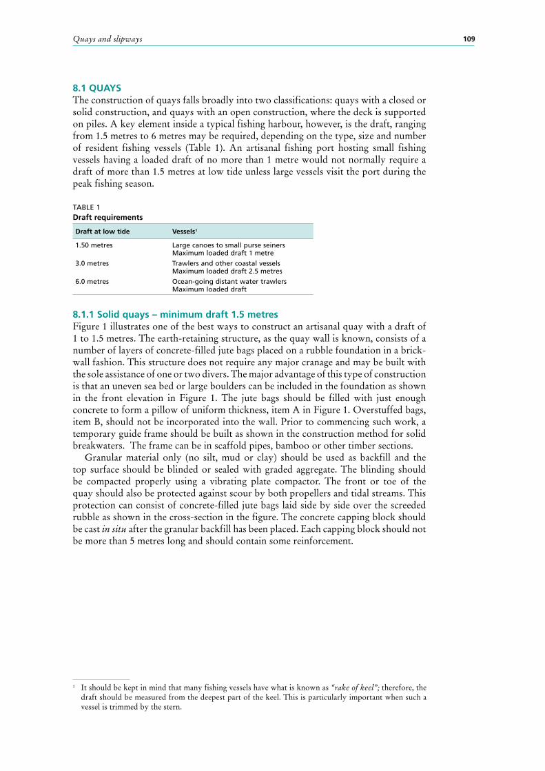
8.1 QUAYSThe construction of quays falls broadly into two classifications: quays with a closed or solid construction, and quays with an open construction, where the deck is supported on piles. A key element inside a typical fishing harbour, however, is the draft, ranging from 1.5 metres to 6 metres may be required, depending on the type, size and number of resident fishing vessels (Table 1). An artisanal fishing port hosting small fishing vessels having a loaded draft of no more than 1 metre would not normally require a draft of more than 1.5 metres at low tide unless large vessels visit the port during the peak fishing season.
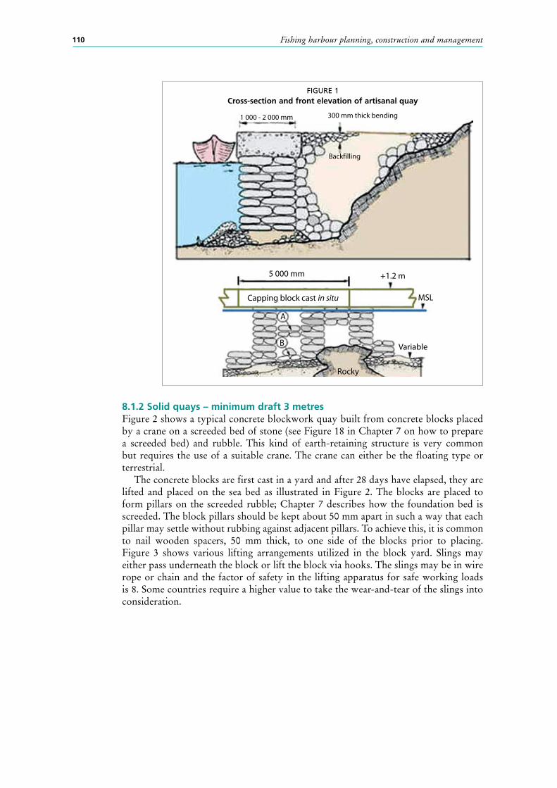
8.1.1 Solid quays – minimum draft 1.5 metresFigure 1 illustrates one of the best ways to construct an artisanal quay with a draft of 1 to 1.5 metres. The earth-retaining structure, as the quay wall is known, consists of a number of layers of concrete-filled jute bags placed on a rubble foundation in a brick-wall fashion. This structure does not require any major cranage and may be built with the sole assistance of one or two divers. The major advantage of this type of construction is that an uneven sea bed or large boulders can be included in the foundation as shown in the front elevation in Figure 1. The jute bags should be filled with just enough concrete to form a pillow of uniform thickness, item A in Figure 1. Overstuffed bags, item B, should not be incorporated into the wall. Prior to commencing such work, a temporary guide frame should be built as shown in the construction method for solid breakwaters. The frame can be in scaffold pipes, bamboo or other timber sections.
Granular material only (no silt, mud or clay) should be used as backfill and the top surface should be blinded or sealed with graded aggregate. The blinding should be compacted properly using a vibrating plate compactor. The front or toe of the quay should also be protected against scour by both propellers and tidal streams. This protection can consist of concrete-filled jute bags laid side by side over the screeded rubble as shown in the cross-section in the figure. The concrete capping block should be cast in situ after the granular backfill has been placed. Each capping block should not be more than 5 metres long and should contain some reinforcement.
TABLE 1 Draft requirements
Draft at low tide Vessels1
1.50 metres Large canoes to small purse seinersMaximum loaded draft 1 metre
3.0 metres Trawlers and other coastal vessels Maximum loaded draft 2.5 metres
6.0 metres Ocean-going distant water trawlersMaximum loaded draft
1 It should be kept in mind that many fishing vessels have what is known as “rake of keel”; therefore, the draft should be measured from the deepest part of the keel. This is particularly important when such a vessel is trimmed by the stern.
Fishing harbour planning, construction and management110
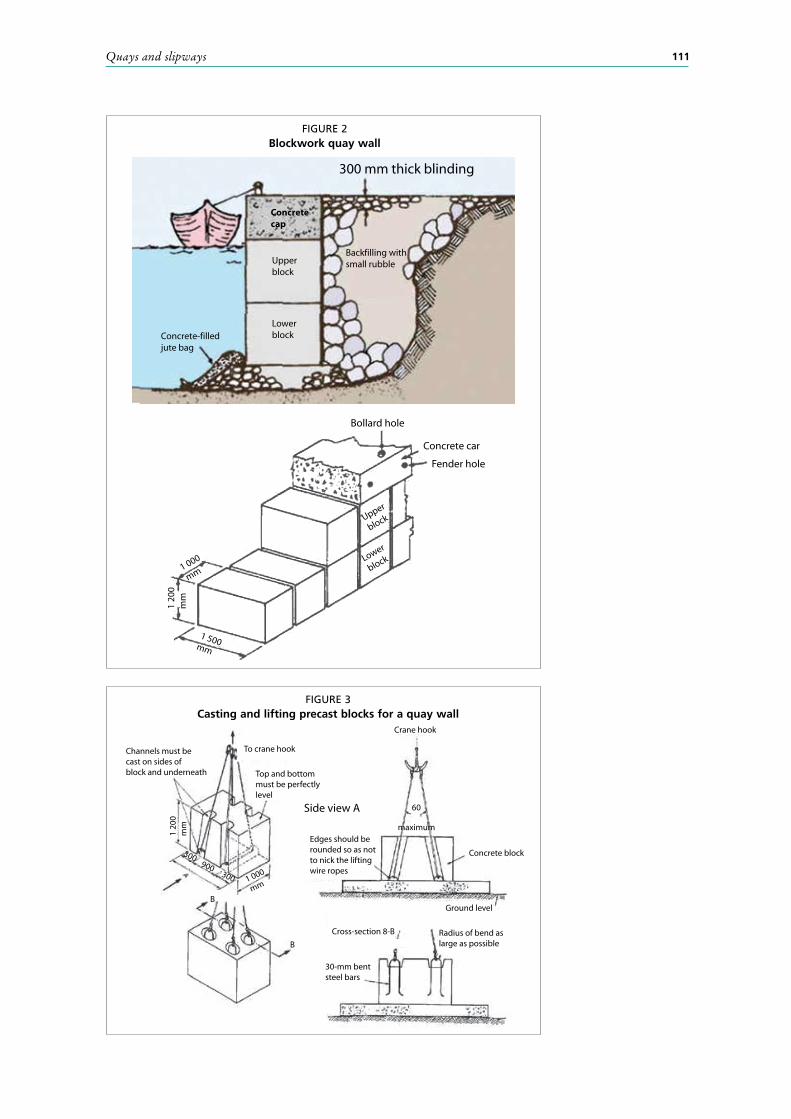
8.1.2 Solid quays – minimum draft 3 metresFigure 2 shows a typical concrete blockwork quay built from concrete blocks placed by a crane on a screeded bed of stone (see Figure 18 in Chapter 7 on how to prepare a screeded bed) and rubble. This kind of earth-retaining structure is very common but requires the use of a suitable crane. The crane can either be the floating type or terrestrial.
The concrete blocks are first cast in a yard and after 28 days have elapsed, they are lifted and placed on the sea bed as illustrated in Figure 2. The blocks are placed to form pillars on the screeded rubble; Chapter 7 describes how the foundation bed is screeded. The block pillars should be kept about 50 mm apart in such a way that each pillar may settle without rubbing against adjacent pillars. To achieve this, it is common to nail wooden spacers, 50 mm thick, to one side of the blocks prior to placing.Figure 3 shows various lifting arrangements utilized in the block yard. Slings may either pass underneath the block or lift the block via hooks. The slings may be in wire rope or chain and the factor of safety in the lifting apparatus for safe working loads is 8. Some countries require a higher value to take the wear-and-tear of the slings into consideration.
FIGURE 1Cross-section and front elevation of artisanal quay
1 000 - 2 000 mm 300 mm thick bending
Backfilling
5 000 mm +1.2 m
Rocky
MSL
Variable
A
B
Capping block cast in situ
Quays and slipways 111
FIGURE 2Blockwork quay wall
300 mm thick blinding
Concretecap
Upperblock
Lower block
Backfilling withsmall rubble
Concrete-filledjute bag
Bollard hole
Concrete car
Fender hole
1 000
mm
Upper
block
Lower
block
1 500mm
1 20
0m
m
FIGURE 3Casting and lifting precast blocks for a quay wall
Channels must becast on sides ofblock and underneath
Side view A
1 20
0m
m
1 000
mm
To crane hook
Top and bottommust be perfectlylevel
Concrete block
Edges should berounded so as notto nick the liftingwire ropes
Radius of bend aslarge as possible
Crane hook
900300
300
30-mm bentsteel bars
Cross-section 8-B
Ground level
60
maximum
B
B
Fishing harbour planning, construction and management112
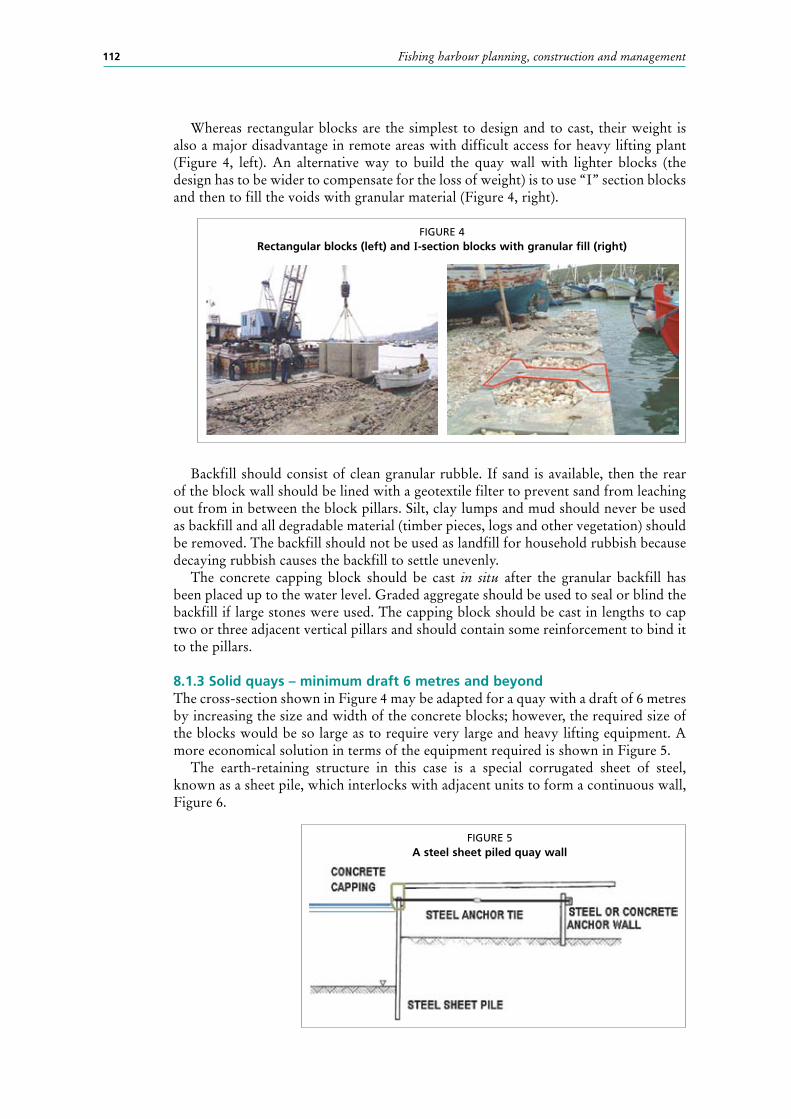
Whereas rectangular blocks are the simplest to design and to cast, their weight is also a major disadvantage in remote areas with difficult access for heavy lifting plant (Figure 4, left). An alternative way to build the quay wall with lighter blocks (the design has to be wider to compensate for the loss of weight) is to use “I” section blocks and then to fill the voids with granular material (Figure 4, right).
Backfill should consist of clean granular rubble. If sand is available, then the rear of the block wall should be lined with a geotextile filter to prevent sand from leaching out from in between the block pillars. Silt, clay lumps and mud should never be used as backfill and all degradable material (timber pieces, logs and other vegetation) should be removed. The backfill should not be used as landfill for household rubbish because decaying rubbish causes the backfill to settle unevenly.
The concrete capping block should be cast in situ after the granular backfill has been placed up to the water level. Graded aggregate should be used to seal or blind the backfill if large stones were used. The capping block should be cast in lengths to cap two or three adjacent vertical pillars and should contain some reinforcement to bind it to the pillars.
8.1.3 Solid quays – minimum draft 6 metres and beyondThe cross-section shown in Figure 4 may be adapted for a quay with a draft of 6 metres by increasing the size and width of the concrete blocks; however, the required size of the blocks would be so large as to require very large and heavy lifting equipment. A more economical solution in terms of the equipment required is shown in Figure 5.
The earth-retaining structure in this case is a special corrugated sheet of steel, known as a sheet pile, which interlocks with adjacent units to form a continuous wall, Figure 6.
FIGURE 4Rectangular blocks (left) and I-section blocks with granular fill (right)
FIGURE 5A steel sheet piled quay wall

Quays and slipways 113
This wall is driven into the sea bed, sheet pile by sheet pile as shown in Figure 7, and the top tied back to an anchor wall, which may consist of a slab of reinforced concrete or a length of the same bulkhead. A temporary timber or steel guide frame is generally erected to help drive the sheet piles vertical and in a straight line. The crane used to drive sheet piles must have a long jib to enable it to pick entire lengths of sheet pile for driving. The crane may either be mounted on a barge, in which case the sheet piles are
FIGURE 6Types of sheet piles in use
FIGURE 7Driving of sheet piles
Fishing harbour planning, construction and management114
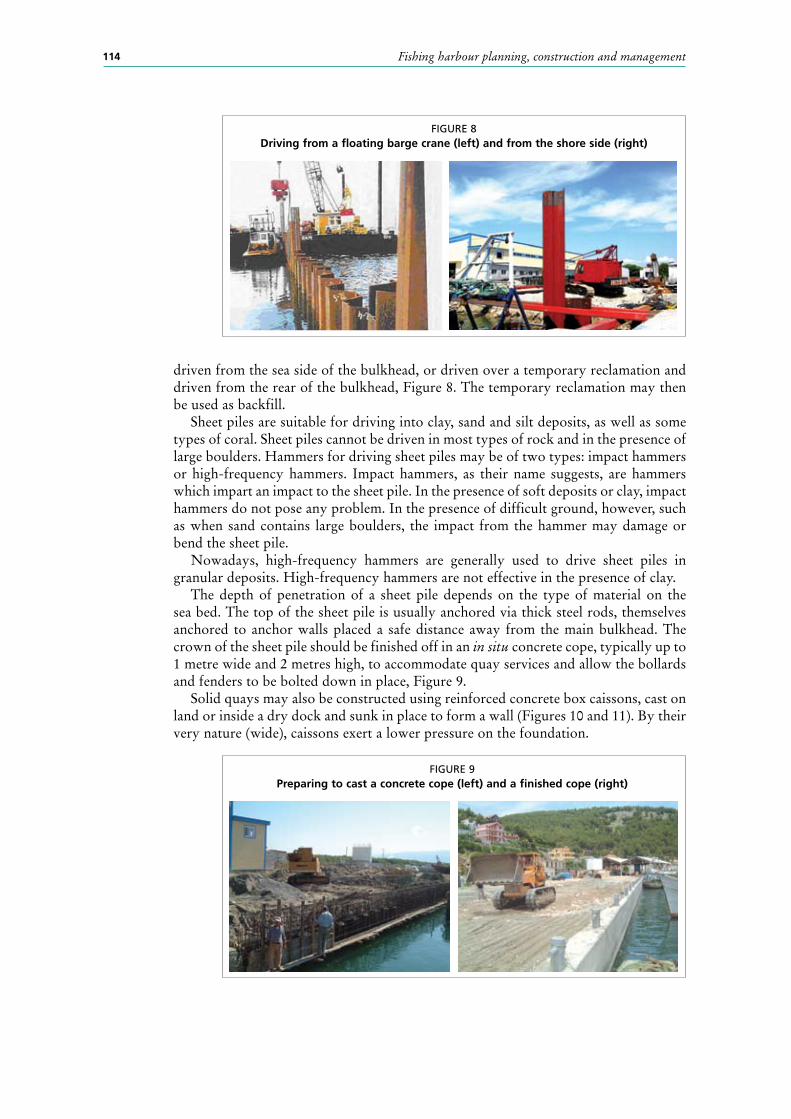
driven from the sea side of the bulkhead, or driven over a temporary reclamation and driven from the rear of the bulkhead, Figure 8. The temporary reclamation may then be used as backfill.
Sheet piles are suitable for driving into clay, sand and silt deposits, as well as some types of coral. Sheet piles cannot be driven in most types of rock and in the presence of large boulders. Hammers for driving sheet piles may be of two types: impact hammers or high-frequency hammers. Impact hammers, as their name suggests, are hammers which impart an impact to the sheet pile. In the presence of soft deposits or clay, impact hammers do not pose any problem. In the presence of difficult ground, however, such as when sand contains large boulders, the impact from the hammer may damage or bend the sheet pile.
Nowadays, high-frequency hammers are generally used to drive sheet piles in granular deposits. High-frequency hammers are not effective in the presence of clay.
The depth of penetration of a sheet pile depends on the type of material on the sea bed. The top of the sheet pile is usually anchored via thick steel rods, themselves anchored to anchor walls placed a safe distance away from the main bulkhead. The crown of the sheet pile should be finished off in an in situ concrete cope, typically up to 1 metre wide and 2 metres high, to accommodate quay services and allow the bollards and fenders to be bolted down in place, Figure 9.
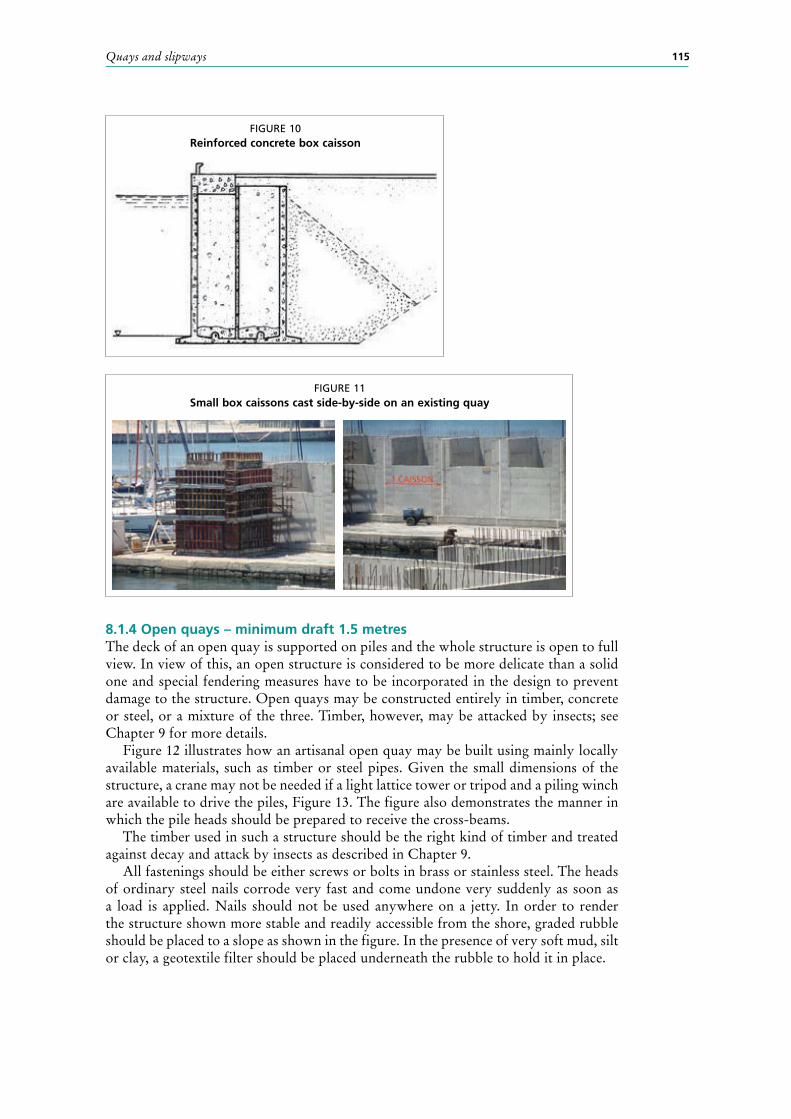
Solid quays may also be constructed using reinforced concrete box caissons, cast on land or inside a dry dock and sunk in place to form a wall (Figures 10 and 11). By their very nature (wide), caissons exert a lower pressure on the foundation.
FIGURE 8Driving from a floating barge crane (left) and from the shore side (right)
FIGURE 9Preparing to cast a concrete cope (left) and a finished cope (right)
Quays and slipways 115
8.1.4 Open quays – minimum draft 1.5 metresThe deck of an open quay is supported on piles and the whole structure is open to full view. In view of this, an open structure is considered to be more delicate than a solid one and special fendering measures have to be incorporated in the design to prevent damage to the structure. Open quays may be constructed entirely in timber, concrete or steel, or a mixture of the three. Timber, however, may be attacked by insects; see Chapter 9 for more details.
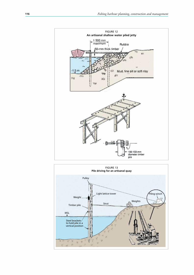
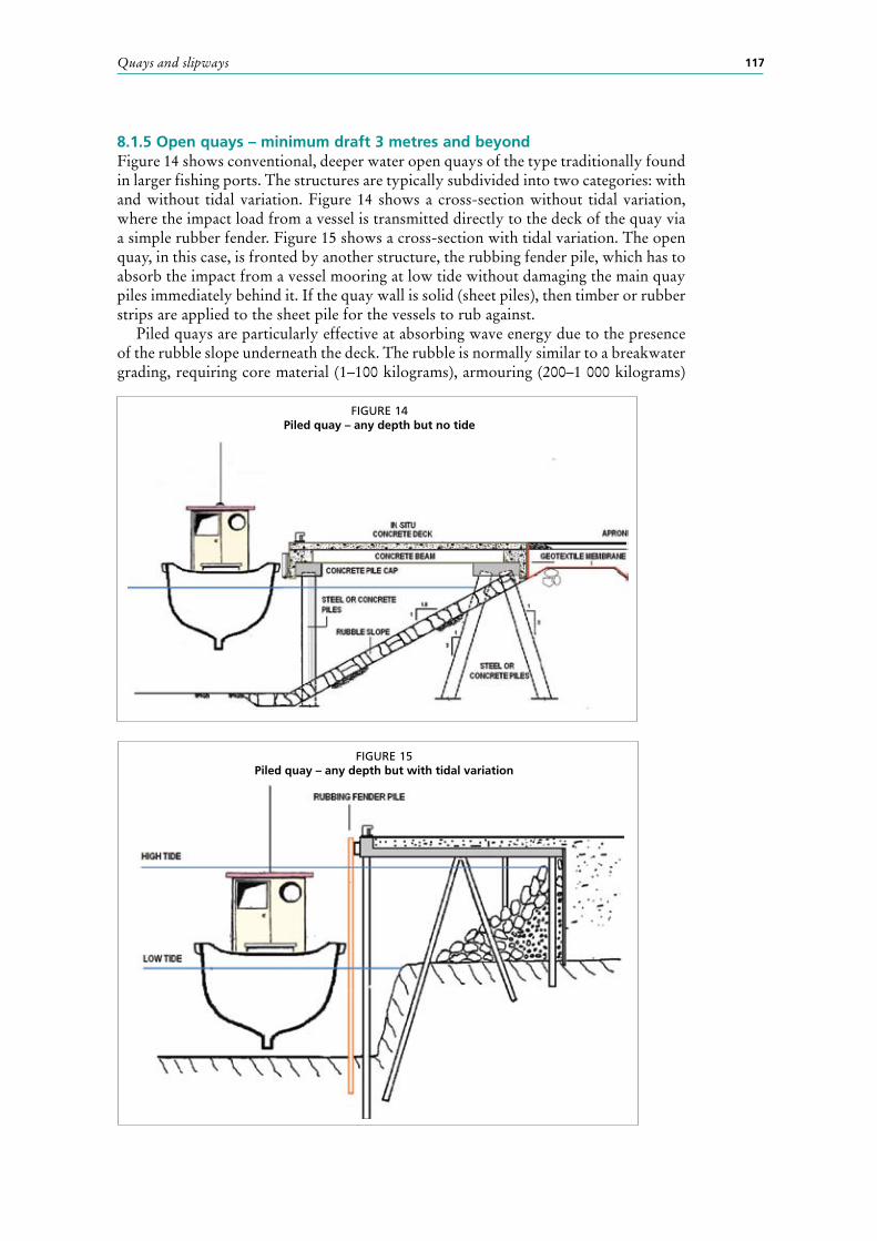
Figure 12 illustrates how an artisanal open quay may be built using mainly locally available materials, such as timber or steel pipes. Given the small dimensions of the structure, a crane may not be needed if a light lattice tower or tripod and a piling winch are available to drive the piles, Figure 13. The figure also demonstrates the manner in which the pile heads should be prepared to receive the cross-beams.
The timber used in such a structure should be the right kind of timber and treated against decay and attack by insects as described in Chapter 9.
All fastenings should be either screws or bolts in brass or stainless steel. The heads of ordinary steel nails corrode very fast and come undone very suddenly as soon as a load is applied. Nails should not be used anywhere on a jetty. In order to render the structure shown more stable and readily accessible from the shore, graded rubble should be placed to a slope as shown in the figure. In the presence of very soft mud, silt or clay, a geotextile filter should be placed underneath the rubble to hold it in place.
FIGURE 10Reinforced concrete box caisson
FIGURE 11Small box caissons cast side-by-side on an existing quay
Fishing harbour planning, construction and management116
FIGURE 12An artisanal shallow water piled jetty
FIGURE 13Pile driving for an artisanal quay
Piling winch
Weights
Weight
Pulley
Light lattice tower
StrutTimber pile
MSL
vertical positionto hold pile in aSteel brackets
Quays and slipways 117
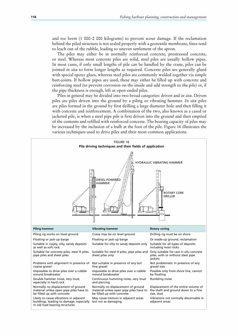
8.1.5 Open quays – minimum draft 3 metres and beyondFigure 14 shows conventional, deeper water open quays of the type traditionally found in larger fishing ports. The structures are typically subdivided into two categories: with and without tidal variation. Figure 14 shows a cross-section without tidal variation, where the impact load from a vessel is transmitted directly to the deck of the quay via a simple rubber fender. Figure 15 shows a cross-section with tidal variation. The open quay, in this case, is fronted by another structure, the rubbing fender pile, which has to absorb the impact from a vessel mooring at low tide without damaging the main quay piles immediately behind it. If the quay wall is solid (sheet piles), then timber or rubber strips are applied to the sheet pile for the vessels to rub against.
Piled quays are particularly effective at absorbing wave energy due to the presence of the rubble slope underneath the deck. The rubble is normally similar to a breakwater grading, requiring core material (1–100 kilograms), armouring (200–1 000 kilograms)
FIGURE 14Piled quay – any depth but no tide
FIGURE 15Piled quay – any depth but with tidal variation
Fishing harbour planning, construction and management118
and toe berm (1 000–2 000 kilograms) to prevent scour damage. If the reclamation behind the piled structure is not sealed properly with a geotextile membrane, fines tend to leach out of the rubble, leading to uneven settlement of the apron.
The piles may either be in normally reinforced concrete, prestressed concrete, or steel. Whereas most concrete piles are solid, steel piles are usually hollow pipes. In most cases, if only small lengths of pile can be handled by the crane, piles can be jointed in situ to form longer lengths as required. Concrete piles are generally glued with special epoxy glues, whereas steel piles are commonly welded together via simple butt-joints. If hollow pipes are used, these may either be filled up with concrete and reinforcing steel (to prevent corrosion on the inside and add strength to the pile) or, if the pipe thickness is enough, left as open-ended piles.
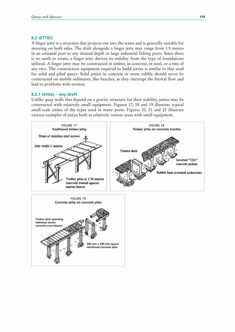
Piles in general may be divided into two broad categories: driven and in situ. Driven piles are piles driven into the ground by a piling or vibrating hammer. In situ piles are piles formed in the ground by first drilling a large diameter hole and then filling it with concrete and reinforcement. A combination of the two, also known as a cased or jacketed pile, is when a steel pipe pile is first driven into the ground and then emptied of the contents and refilled with reinforced concrete. The bearing capacity of piles may be increased by the inclusion of a bulb at the foot of the pile. Figure 16 illustrates the various techniques used to drive piles and their most common applications.
FIGURE 16Pile driving techniques and their fields of application
Piling hammer Vibrating hammer Rotary coring
Piling rig works on level ground
Floating or jack-up barge
Crane may be on level ground
Floating or jack-up barge
Drilling rig must be on shore
Or made-up ground, reclamation
Suitable in clayey, silty, sandy deposits as well as soft rock
Suitable for silty to sandy deposits only Suitable for all types of deposits including most rocks
Suitable for concrete piles, steel H piles, pipe piles and sheet piles
Suitable for steel H piles, pipe piles and sheet piles only
Only suitable for cast in situ concrete piles, with or without steel pipe jackets
Problems with alignment in presence of coarse gravel
Not suitable in presence of any but fine gravel
Not problematic in presence of any gravel size
Impossible to drive piles over a rubble mound breakwater
Impossible to drive piles over a rubble mound breakwater
Possible only from shore line, cannot be floating
Double hammer noise, very loud, especially in hard rock
Continuous humming noise, very loud and piercing
Rumbling noise
Normally no displacement of ground material unless open pipe piles have to be filled up with concrete
Normally no displacement of ground material unless open pipe piles have to be filled up with concrete
Displacement of the entire volume of the shaft and ground down to a fine size, dust
Likely to cause vibrations in adjacent buildings, leading to damage, especially in old load bearing structures
May cause tremors in adjacent areas but not as damaging
Vibrations not normally discernable in adjacent areas
DIESEL-POWERED HAMMER
HYDRAULIC VIBRATING HAMMER
ROTARY CORE DRILLER
Quays and slipways 119
8.2 JETTIESA finger jetty is a structure that projects out into the water and is generally suitable for mooring on both sides. The draft alongside a finger jetty may range from 1.5 metres in an artisanal port to any desired depth in large industrial fishing ports. Since there is no earth to retain, a finger jetty derives its stability from the type of foundations utilized. A finger jetty may be constructed in timber, in concrete, in steel, or a mix of any two. The construction equipment required to build jetties is similar to that used for solid and piled quays. Solid jetties in concrete or stone rubble should never be constructed on mobile sediments, like beaches, as they interrupt the littoral flow and lead to problems with erosion.
8.2.1 Jetties – any draftUnlike quay walls that depend on a gravity structure for their stability, jetties may be constructed with relatively small equipment. Figures 17, 18 and 19 illustrate typical small-scale jetties of the types used in many ports. Figures 20, 21 and 22 illustrate various examples of jetties built in relatively remote areas with small equipment.
FIGURE 17Traditional timber jetty
FIGURE 18Timber jetty on concrete trestles
FIGURE 19Concrete jetty on concrete piles
Timber deck spanningsideways acrossconcrete cross-beams
300 mm x 300 mm squarereinforced concrete piles

Fishing harbour planning, construction and management120
FIGURE 20Precast concrete trestles (left) and concrete jetty under construction (right)
FIGURE 21Timber jetty (left) and steel jetty (right)
FIGURE 22Concrete jetty built with modular units from land
8.2.2 Floating jettiesFloating jetties come in a whole range of sizes and shapes to cater for vessels ranging from a small canoe to an ocean-going trawler.
Figure 23 illustrates a jetty in timber which may be manufactured from locally available materials like plastic or oil drums, timber and fibre rope. Figure 24 illustrates the Jetfloat unit, a commercially available system, consisting of modular floats in plastic that join up to form a floating platform of any desired shape.

Quays and slipways 121
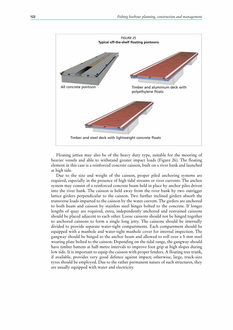
Ready-made pontoons in concrete or a combination of timber, metal, concrete or plastic may be purchased from a variety of sources (Figure 25). Sizes range from6 metres to 12 metres and widths vary from 1.5 metres to 3.5 metres. All pontoons should be installed in sheltered waters with little or no current.
FIGURE 23Floating jetty in timber – local artisanal manufacture
FIGURE 24Floating jetty in off-the-shelf modular plastic float units
2 00
0
REINFORCED CONCRETEJETFLOAT ANCHOR BLOCK
Fishing harbour planning, construction and management122
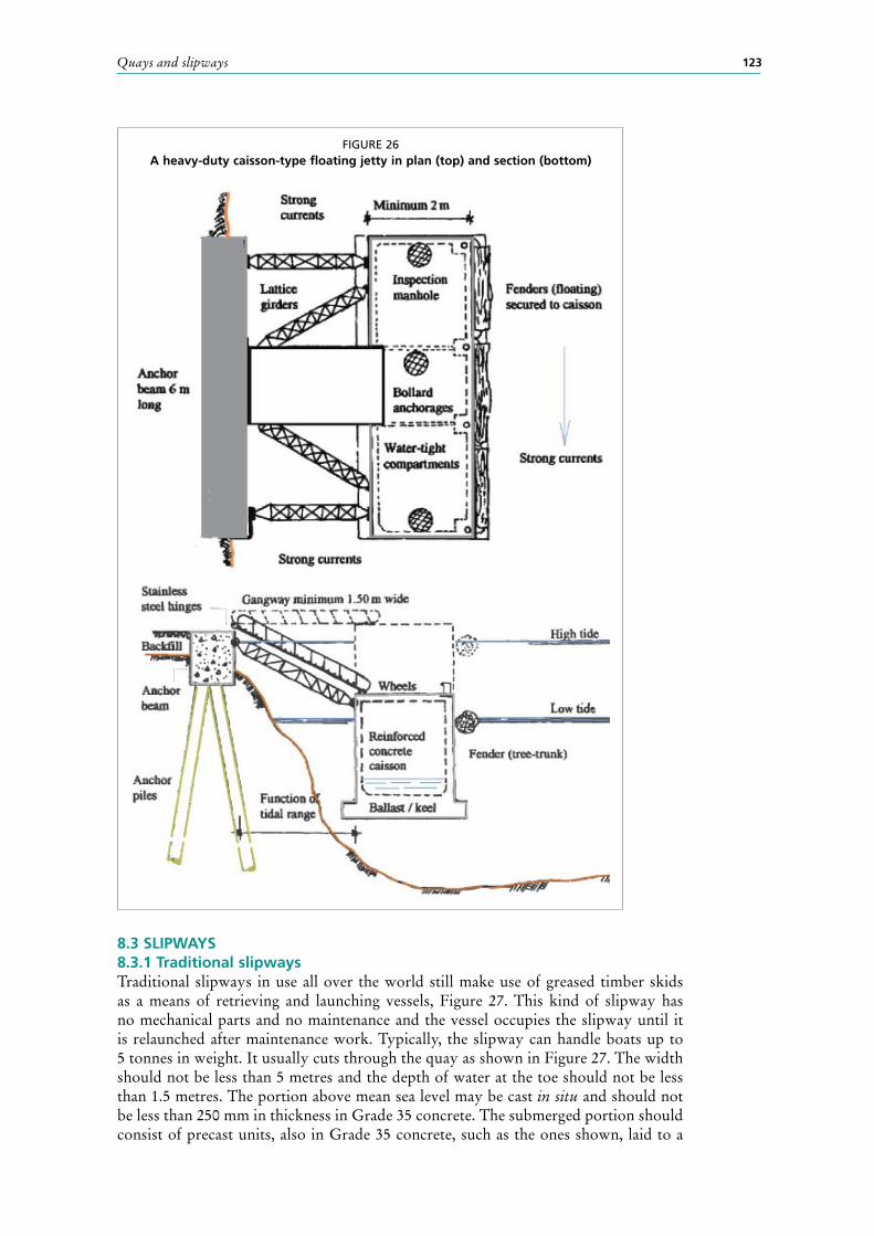
Floating jetties may also be of the heavy duty type, suitable for the mooring of heavier vessels and able to withstand greater impact loads (Figure 26). The floating element in this case is a reinforced concrete caisson, built on a river bank and launched at high tide.
Due to the size and weight of the caisson, proper piled anchoring systems are required, especially in the presence of high tidal streams or river currents. The anchor system may consist of a reinforced concrete beam held in place by anchor piles driven into the river bank. The caisson is held away from the river bank by two outrigger lattice girders perpendicular to the caisson. Two further inclined girders absorb the transverse loads imparted to the caisson by the water current. The girders are anchored to both beam and caisson by stainless steel hinges bolted to the concrete. If longer lengths of quay are required, extra, independently anchored and restrained caissons should be placed adjacent to each other. Loose caissons should not be hinged together to anchored caissons to form a single long jetty. The caissons should be internally divided to provide separate water-tight compartments. Each compartment should be equipped with a manhole and water-tight manhole cover for internal inspection. The gangway should be hinged to the anchor beam and allowed to roll over a 5 mm steel wearing plate bolted to the caisson. Depending on the tidal range, the gangway should have timber battens at half-metre intervals to improve foot grip at high slopes during low tide. It is important to equip the caisson with proper fenders. A floating tree trunk, if available, provides very good defence against impact; otherwise, large, truck-size tyres should be employed. Due to the rather permanent nature of such structures, they are usually equipped with water and electricity.
FIGURE 25Typical off-the-shelf floating pontoons
All concrete pontoon Timber and aluminium deck with polyethylene floats
Timber and steel deck with lightweight concrete floats
Quays and slipways 123
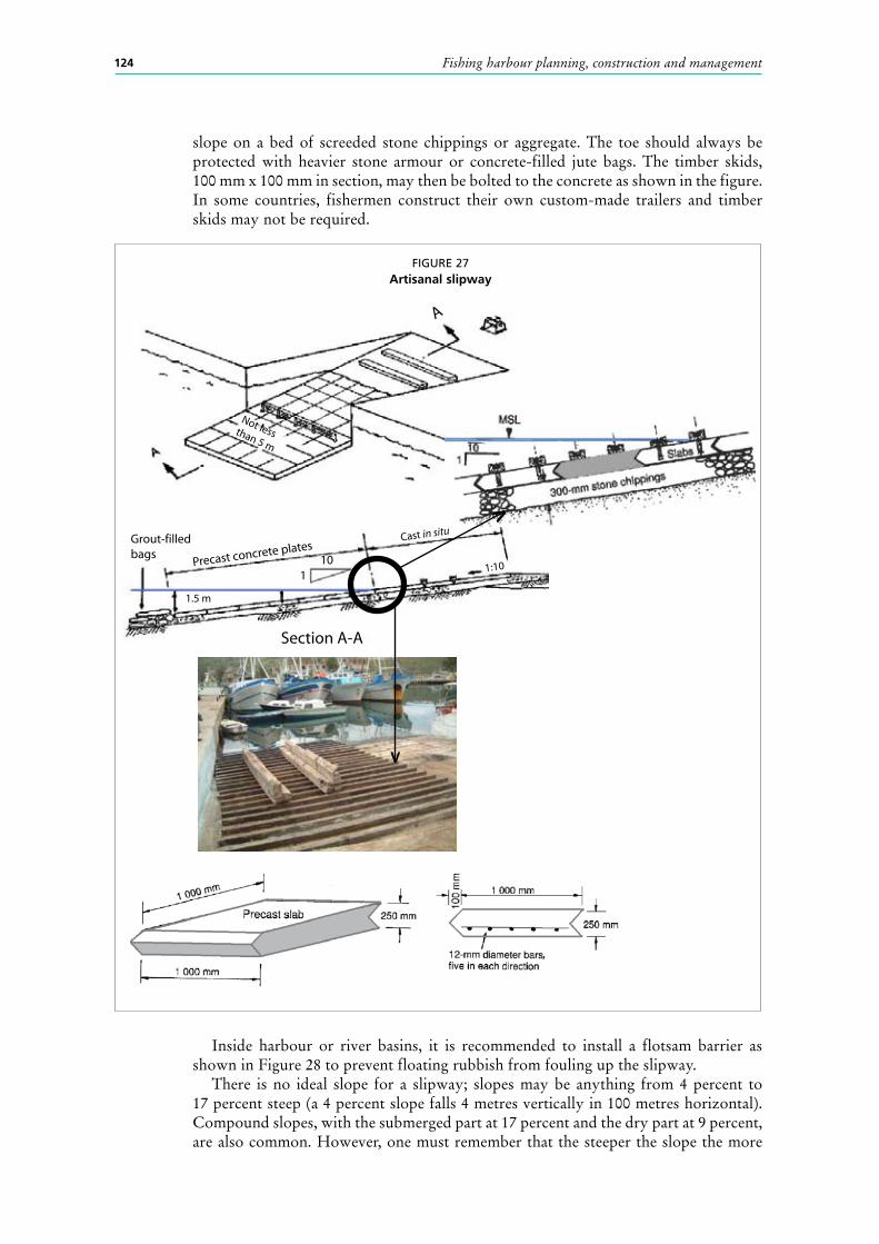
8.3 SlIPWAYS8.3.1 Traditional slipwaysTraditional slipways in use all over the world still make use of greased timber skids as a means of retrieving and launching vessels, Figure 27. This kind of slipway has no mechanical parts and no maintenance and the vessel occupies the slipway until it is relaunched after maintenance work. Typically, the slipway can handle boats up to 5 tonnes in weight. It usually cuts through the quay as shown in Figure 27. The width should not be less than 5 metres and the depth of water at the toe should not be less than 1.5 metres. The portion above mean sea level may be cast in situ and should not be less than 250 mm in thickness in Grade 35 concrete. The submerged portion should consist of precast units, also in Grade 35 concrete, such as the ones shown, laid to a
FIGURE 26A heavy-duty caisson-type floating jetty in plan (top) and section (bottom)
Fishing harbour planning, construction and management124
slope on a bed of screeded stone chippings or aggregate. The toe should always be protected with heavier stone armour or concrete-filled jute bags. The timber skids, 100 mm x 100 mm in section, may then be bolted to the concrete as shown in the figure. In some countries, fishermen construct their own custom-made trailers and timber skids may not be required.
FIGURE 27Artisanal slipway
A
Not lessthan 5 m
Grout-filledbags
Precast concrete plates
1
1.5 m
Cast in situ
1:10
Section A-A
10
,
V
V
Inside harbour or river basins, it is recommended to install a flotsam barrier as shown in Figure 28 to prevent floating rubbish from fouling up the slipway.
There is no ideal slope for a slipway; slopes may be anything from 4 percent to 17 percent steep (a 4 percent slope falls 4 metres vertically in 100 metres horizontal). Compound slopes, with the submerged part at 17 percent and the dry part at 9 percent, are also common. However, one must remember that the steeper the slope the more

Quays and slipways 125
powerful the winch has to be and that the submerged part may be steeper (the vessel weighs less when in the water) for the same type of winch. Slipway equipment is illustrated in Chapter 10.
8.3.2 Slipways on beachesIt is not uncommon for heavy boatyards, which handle vessels above 5 tonnes, to be located out of town in the vicinity of a sandy coastline. Ideally, no obstructions should be constructed on a sandy beach as these give rise to erosion. Such a structure will invariably need constant dredging to keep the axis free of accumulated sand. Decked boats, including small trawlers, may be safely beached on sand if this method had been taken into consideration at the vessel design stage. Where bilge keels are attached to the sides of the hull to keep it upright they should be so designed to support the weight exerted by the vessel and the keels of wooden hulled and fibreglass vessels should be protected by a skid bar. This might be a stainless steel rubbing plate bolted to the bottom of the keel on a wooden vessel or more probably hard wood in the case of a fibreglass vessel. The end of the skeg may be curved to avoid digging in on launching. A small tractor or winch may be used to haul the vessels ashore (Figure 29).
Launching is clearly a reverse process with the same winch or tractor hauling the boat against a secure anchoring point in the water. In both landing and launching, wooden skids or rollers below the keel are often used; see section 10.7 of Chapter 10.
FIGURE 28Flotsam barrier
FIGURE 29Beaching a vessel
Fishing harbour planning, construction and management126
8.3.3 Mechanical slipways – all sizesMechanically operated slipping facilities may be divided into three categories for all vessels up to 500 tonnes displacement. The three methods are:
• mechanized slipway;• mobile gantry or travelift; and• synchrolift or ship lift.
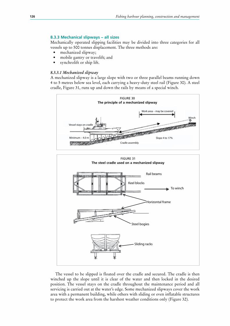
8.3.3.1 Mechanized slipwayA mechanized slipway is a large slope with two or three parallel beams running down 4 to 5 metres below sea level, each carrying a heavy-duty steel rail (Figure 30). A steel cradle, Figure 31, runs up and down the rails by means of a special winch.
The vessel to be slipped is floated over the cradle and secured. The cradle is then winched up the slope until it is clear of the water and then locked in the desired position. The vessel stays on the cradle throughout the maintenance period and all servicing is carried out at the water’s edge. Some mechanized slipways cover the work area with a permanent building, while others with sliding or even inflatable structures to protect the work area from the harshest weather conditions only (Figure 32).
FIGURE 30The principle of a mechanized slipway
Vessel stays on cradle
Minimum – 4.0 m
Cradle assembly
Slope 4 to 17%
Winch
Work area – may be covered
FIGURE 31The steel cradle used on a mechanized slipway
Keel blocks
To winch
Rail beams
Horizontal frame
Steel bogies
Sliding racks<
<
<
<
Quays and slipways 127
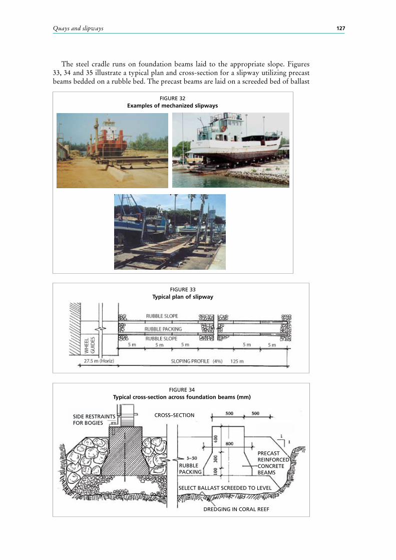
The steel cradle runs on foundation beams laid to the appropriate slope. Figures 33, 34 and 35 illustrate a typical plan and cross-section for a slipway utilizing precast beams bedded on a rubble bed. The precast beams are laid on a screeded bed of ballast
FIGURE 32Examples of mechanized slipways
FIGURE 33Typical plan of slipway
FIGURE 34Typical cross-section across foundation beams (mm)
SIDE RESTRAINTS FOR BOGIES
CROSS–SECTION
RUBBLE PACKING
SELECT BALLAST SCREEDED TO LEVEL
DREDGING IN CORAL REEF
PRECAST REINFORCED CONCRETEBEAMS

Fishing harbour planning, construction and management128
or coarse aggregate and the adjoining spaces packed with 5 to 50 kilogram rock. A wheel side-restraint in galvanized angle ensures that the cradle does not run off the concrete surface. The wheel or group of wheels or bogies are normally in solid steel coated with rubber. Steel rails may also be used over the beams.
8.3.3.2 Mobile gantry or traveliftA mobile gantry or travelift facility typically consists of a rubber-tyred gantry running over a twin pier construction (Figures 36, 37 and 38). The vessels to be slipped are floated in between the piers and then hoisted out of the water by the mobile gantry or travelift using polyester straps.
FIGURE 35Typical precast beams
5 000 mm
HOLES FOR MS φ 20 mm ANCHOR BOLTS
VERTICAL KEYS
FIGURE 36Mobile gantry
Front elevationacross vessel pen
Capacity 500 tonnes max
To open workarea or coveredworkshops
Wheel stop
<
Quays and slipways 129
2 The sketches do not show in detail the arrangements to keep the wheels from running “off track” and for the wheel stops.
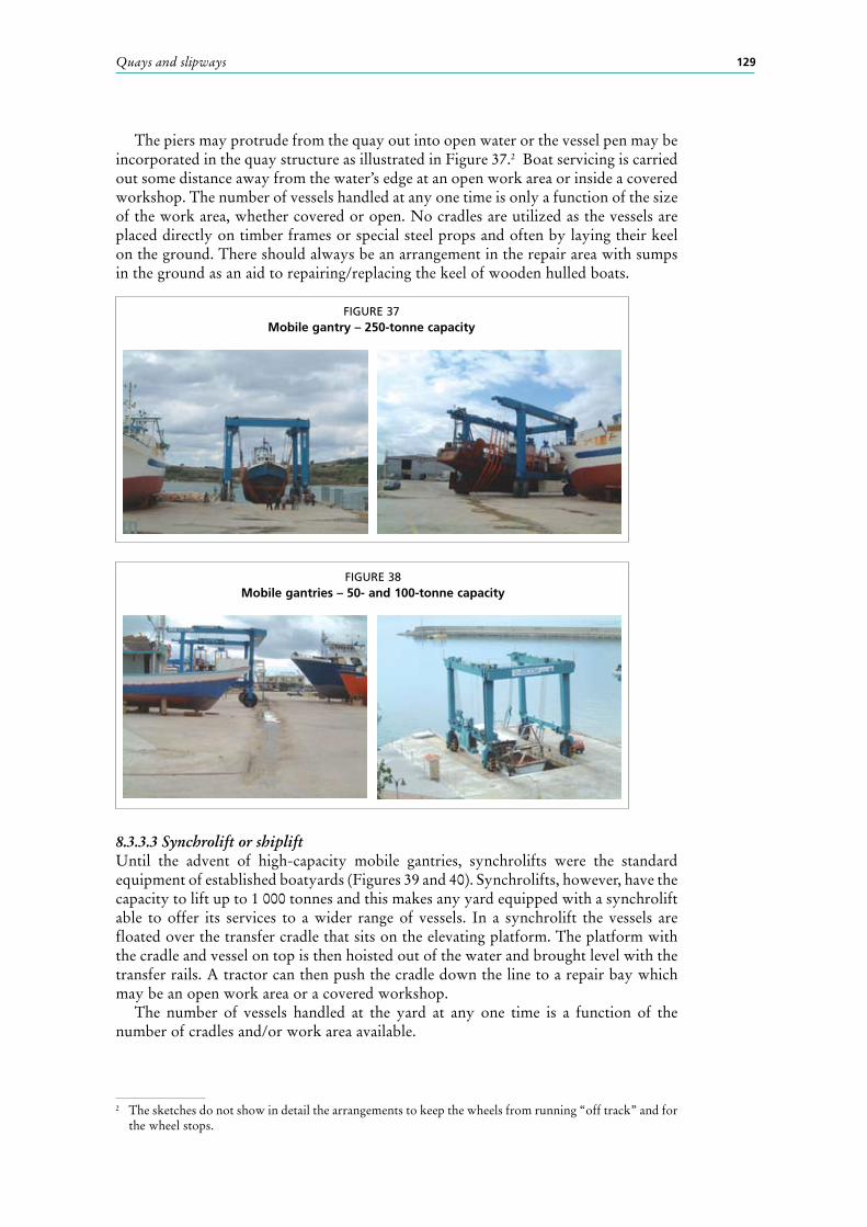
The piers may protrude from the quay out into open water or the vessel pen may be incorporated in the quay structure as illustrated in Figure 37.2 Boat servicing is carried out some distance away from the water’s edge at an open work area or inside a covered workshop. The number of vessels handled at any one time is only a function of the size of the work area, whether covered or open. No cradles are utilized as the vessels are placed directly on timber frames or special steel props and often by laying their keel on the ground. There should always be an arrangement in the repair area with sumps in the ground as an aid to repairing/replacing the keel of wooden hulled boats.
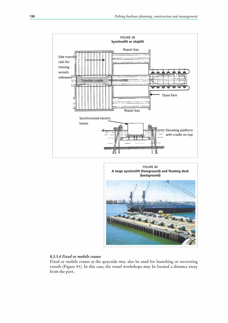
8.3.3.3 Synchrolift or shipliftUntil the advent of high-capacity mobile gantries, synchrolifts were the standard equipment of established boatyards (Figures 39 and 40). Synchrolifts, however, have the capacity to lift up to 1 000 tonnes and this makes any yard equipped with a synchrolift able to offer its services to a wider range of vessels. In a synchrolift the vessels are floated over the transfer cradle that sits on the elevating platform. The platform with the cradle and vessel on top is then hoisted out of the water and brought level with the transfer rails. A tractor can then push the cradle down the line to a repair bay which may be an open work area or a covered workshop.
The number of vessels handled at the yard at any one time is a function of the number of cradles and/or work area available.
FIGURE 37Mobile gantry – 250-tonne capacity
FIGURE 38Mobile gantries – 50- and 100-tonne capacity
Fishing harbour planning, construction and management130
8.3.3.4 Fixed or mobile cranesFixed or mobile cranes at the quayside may also be used for launching or recovering vessels (Figure 41). In this case, the vessel workshops may be located a distance away from the port.
FIGURE 39Synchrolift or shiplift
Repair bay
Repair bay
Side transfer rails for moving vessels sideways
Transfer cradle
Quay face
Eleva�ng pla�orm with cradle on top
Synchronized electric hoists
FIGURE 40A large synchrolift (foreground) and floating dock
(background)

Quays and slipways 131
8.3.4 Vessel repair facilities8.3.4.1 Best management practiceVessel repair facilities pose special environmental concerns in a fishing port because of the processes and chemical materials that they use and their proximity to areas where fish meant for human consumption is handled. The area of major concern in a boatyard is hull stripping and painting.
When a vessel’s hull is prepared for painting the process typically starts with pressure or mechanical (hand brush) washing to remove the marine organisms and slime accumulated between maintenance intervals, Figure 42.
Next, depending on whether the hull is metal or timber or glass reinforced plastic (GRP), the antifouling paint is stripped by grit blasting or mechanical sander. Both grit blasting and sanding tend to raise particulate matter into the surrounding environment and in windy conditions the entire port may be enveloped in a cloud of potentially harmful particulate matter.
Similarly, if it rains, the dust settled under the vessel may be washed back into the sea. Figure 43 illustrates how a covered work area around the vessel may be set up using simple plastic sheeting clamped to the vessel’s coaming and held down at ground level with simple upright poles driven into the ground.
FIGURE 41Mobile or fixed cranes used to launch or recover vessels
FIGURE 42Power washing hull

Fishing harbour planning, construction and management132
The following recommended work practices should be observed at the slipway:Hull cleaning• perform abrasive or sanding under covered tarpaulin enclosures or boat skirts;• perform abrasive or sanding over a horizontal hard impermeable surface, such as
concrete, to enable proper cleaning of surface and collection of wastes;• whenever possible, use vacuum sanders to limit the amount of dust generated;• sanding dust and paint chippings must be removed on a daily basis and appropriate
covered waste containers should be provided within the facility;• workers under the boat skirt should be provided with appropriate full-face masks;
and• a list of the above work practices should be posted at the work area for the
benefit of the “do-it-yourself” vessel owners who may not be aware of the port’s environmental regulations.
Hull painting• techniques such as brushing and rolling are preferred to spraying to reduce
overspray and solvent emissions;• all painting should be performed under covered tarpaulin enclosures or boat
skirts;• all painting should be performed over a horizontal hard impermeable surface;• whenever possible, solvents and coatings with low volatility should be used;• waste paints, solvents and rags should be stored in covered waste containers to
prevent evaporation to the atmosphere; and• workers under the boat skirt should be provided with appropriate full-face masks
and solvent-resistant gloves.
8.4 BIBlIOGRAPHY AnD FURTHER READInGBritish Steel. 1988. Piling Handbook. British Steel, PO Box 30, Motherwell ML1AA,
UK.Committee for Waterfront Structures. 1982. Recommendations of the Committee for
Waterfront Structures. Berlin, Wilhelm Ernst & Sohn.Naval Facilities Engineering Command. 1989. Marine Railways. Alexandria, Virginia,
NavFacEngCom.Quinn, A.D. 1972. Design and Construction of Ports and Marine Structures. McGraw-
Hill, Inc., New York.
FIGURE 43Covered work area around a vessel, also known as a boat skirt
CLAMPED TOCOAMING
TARPAULIN ORPLASTIC SHEET
WEIGHTSUPRIGHT
STRUTS
KEEL BLOCK
COVEREDWORK AREA