07 Wildgust Geological Storage - ccs- · PDF file• Data rich (lots of wells, ... produce...
22
Geological Storage Neil Wildgust CCS – Africa Workshops April 2010
Transcript of 07 Wildgust Geological Storage - ccs- · PDF file• Data rich (lots of wells, ... produce...

Geological Storage
Neil WildgustCCS – Africa Workshops
April 2010

Contents of Talk
• 1. Introduction to IEAGHG• 2. Overview of CO 2 Geological Storage• 3. Storage Systems• 4. Storage Capacity• 4. Storage Capacity• 5. Current Projects• 6. Summary and Challenges Ahead

IEAGHG

Geological Storage of CO 2
• Requires three ingredients for success:
•Capacity• Injectivity• Injectivity•Containment

RESERVOIR ROCK – porous, e.g. sandstone
Claystone SEAL ROCK – non-porous, e.g. claystone
What do we need?
Geological Storage of COGeological Storage of CO 22
How does it work?
• CO2 injected into porous reservoir rock
• CO2 held in place by overlying non-porous seal rock
Sandstone reservoir rock
Claystone cap rock
porous, e.g. claystone
Courtesy Kaldi, 2009

COCO22 Properties change with DepthProperties change with Depth
Courtesy Kaldi, 2009

Wells and Logging
Courtesy Kaldi, 2009

Seismic Surveys
Seismic imaging uses reflected sound waves to create a picture of underground rock formations. It can show potential CO2 reservoirs and seal rocks and other geologic features such as faults. After injection begins, it can show the location of the CO2.
Courtesy Kaldi, 2009

Geological Storage Systems for CO2
6. Low probability; Niche opportunities only
IPCC 2005
5. Limited CSM production.Considerable future CSM
potential, limited storage volumes
1. Some depleted reservoirsavailable now; but
most volume available in> 40 years; most information
4. Limited to depthsbelow future mininglimits (600->1000m)likely permeability
problems
2. Main focus of oil & gas
industrybut limited volumes
3. Worldwide geology suggests that this hasboth greatest potential
volumes; and most favourable economics
IPCC 2005

Deep Saline Formations
Trapping mechanisms
StructuralResidualResidualSolutionMineral
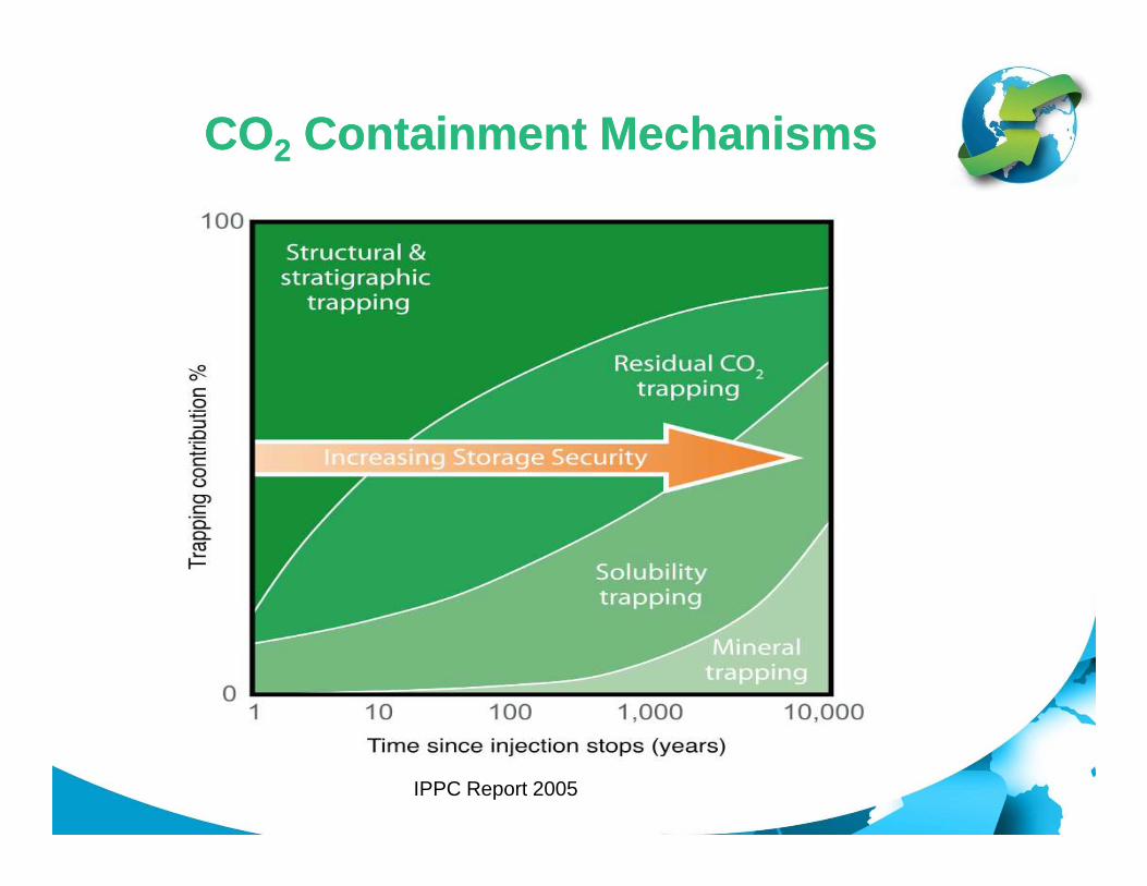
COCO22 Containment MechanismsContainment Mechanisms
IPPC Report 2005

Oil & Gas Reservoirs: EOR with CO 2 Storage
• Proven containment (seal held oil & gas)• Data rich (lots of wells, • Data rich (lots of wells, seismic)• Objective: produce more oil (CO2 storage secondary!)
Courtesy Kaldi, 2009

CO2 Storage in CoalSequences
CO2 storage potential may include coal systems (coal se ams and associated sediments) as well as the storage potent ial arising from using CO 2 for Enhanced Coal Bed Methane Recovery
Courtesy Kaldi, 2009

Coal bed storage

Storage Capacity EstimationStorage Capacity Estimation
Decreasing Storage Capacity;
Increasing Certainty;
Data / Effort Data / Effort Required
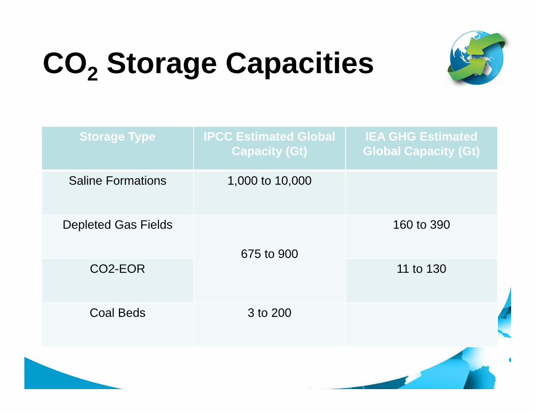
CO2 Storage Capacities
Storage Type IPCC Estimated Global Capacity (Gt)
IEA GHG Estimated Global Capacity (Gt)
Saline Formations 1,000 to 10,000
Depleted Gas Fields
675 to 900
160 to 390
CO2-EOR 11 to 130
Coal Beds 3 to 200

SnøhvitSleipner
CommercialCommercial--scale CCS Projectsscale CCS Projects
Weyburn/Midale
In-Salah
Images Courtesy of BP, Statoil, and PTRC

Bellingham Cogeneration Facility
IFFCO CO2 Recovery Plant –Aonla
CASTOR Project Prosint Methanol PlantGreat Plains Synfuel Plant Rangely CO2 ProjectIMC Global Soda Plant Schwarze PumpeIn Salah SECARB - Cranfield IIK12-B Shady Point Power Plant
Bellingham Cogeneration Facility
IFFCO CO2 Recovery Plant –Aonla
CASTOR Project Prosint Methanol PlantGreat Plains Synfuel Plant Rangely CO2 ProjectIMC Global Soda Plant Schwarze PumpeIn Salah SECARB - Cranfield IIK12-B Shady Point Power Plant
CCS Projects identified
Capture over 100ktCO2
Injection over 10ktCO2 for K12-B Shady Point Power Plant
Ketzin Project SleipnerMRCSP - Michigan Basin Snohvit LNG ProjectNagaoka SRCSP - Aneth EOR-Paradox BasinOtway Basin Project SRCSP - San Juan BasinPembina Cardium Project Sumitomo Chemicals PlantPetronas Fertilizer Plant Warrior Run Power PlantIFFCO CO2 Recovery Plant -Phulpur WeyburnChemical Co. “A” CO2 Recovery Plant Zama EOR Project
K12-B Shady Point Power PlantKetzin Project SleipnerMRCSP - Michigan Basin Snohvit LNG ProjectNagaoka SRCSP - Aneth EOR-Paradox BasinOtway Basin Project SRCSP - San Juan BasinPembina Cardium Project Sumitomo Chemicals PlantPetronas Fertilizer Plant Warrior Run Power PlantIFFCO CO2 Recovery Plant -Phulpur WeyburnChemical Co. “A” CO2 Recovery Plant Zama EOR Project
10ktCO2 for storage
Monitored EOR over 10ktCO2
Capture over 10ktCO2 from flue gas
Coal bed storage over 10ktCO2

Extent of coverage vs ZEP project matrix
Demonstrated in operational large projects
Not demonstrated in operational large projects
Project matrix courtesy of EU Technology Platform for Zero Emission Fossil Fuel Power Plants - ZEP (2008)

Summary – current status
o Injection of CO 2 into depleted oil fields (CO2-EOR) and deep saline formations (CCS demo’s) is technologica lly proven
o IEAGHG survey – nearly 10Mt CO 2 per annum collectively stored around world by end of 2008, excluding commercial CO2-EOR
o Deep saline formations widely considered to have greatest volumetric potential
o Storage in other geological media is less certain o r unproven, e.g. basalts, shales, coal beds

Storage Challenges
• Implementation of commercial scale CCS• Pressure build up and brine displacement
in deep saline formation storage• Public outreach and communication• Public outreach and communication• Long term liability issues• Other technical challenges are not
considered to be ‘show-stoppers’

Thank you for your attention