
06843166
6
Experimental performance bounds of MIMO-FBMC/OQAM systems M` arius Caus ∗ and Ana I. Perez-Neira ∗† ∗ Dept. of Signal Theory and Communications - Universitat Polit` ecnica de Catalunya (UPC), Campus Nord, Jordi Girona 1-3, 08034 Barcelona, Spain † Centre Tecnol` ogic de Telecomunicacions de Catalunya (CTTC), Av. Carl Friedrich Gauss 7, B4 08860 Castelldefels, Barcelona, Spain Abstract—This paper addresses the application of filter bank multicarrier (FBMC) systems to multiple-input-multiple-output (MIMO) channels. In particular, it is investigated the FBMC modulation based on OQAM, known as FBMC/OQAM. Existing solutions reveal that FBMC/OQAM remains competitive with the orthogonal frequency division multiplexing (OFDM) technique when the number of streams (S), transmit antennas (NT ) and receive antennas (NR) are related as follows: S = min(NT ,NR). State-of-the-art techniques fail to achieve satisfactory results in FBMC/OQAM systems when S < min(NT ,NR). That is because the strongest spatial subchannels exhibit higher gains in MIMO-OFDM than in existing MIMO-FBMC/OQAM systems. To determine if FBMC/OQAM can be successfully applied when strict inequality holds, this paper provides experimental performance bounds, which can be assumed to approximate the optimal performance. In this sense, numerical results show that FBMC/OQAM is able to slightly outperform OFDM when S< min(NT ,NR) by attenuating the residual interference 20 dB below the equalized noise. This insightful information could be used in the design process of future techniques to approach the experimental performance bounds. I. I NTRODUCTION In the light of previous forecasts, the International Telecommunication Union Radiocommunication Sector has concluded that the mobile data traffic will dramatically in- crease over the next decade [1]. This fact highlights that the capacity of the state-of-the-art cellular networks may be insufficient to satisfy the upcoming needs. Some measures that are being considered to respond to the traffic increase include: the use of multiple-input-multiple-output (MIMO) technol- ogy, coordinated multipoint (CoMP) techniques, authorized spectrum sharing and cellular interworking with other access technologies, just to mention some of them. The use of the aforementioned technologies contributes to reach the future goals, but in exchange networks may become more heterogeneous since different communication systems co-exist in the same geographical location and sometimes compete for the same frequency resources. In this context, strict synchronization and complete coordination between all the wireless communication systems is required to avoid in- terference. This approach is not always practical because a lot of signaling may be involved resulting in a substantial spectral efficiency degradation. To overcome this issue, systems should be designed to be tolerant to interference. Then, the bandwidth efficiency may increase by reducing the signaling, as synchro- nization requirements could be relaxed. The difficulty of oper- ating under perfect synchronization highlights the necessity of using spectrally-agile waveforms with a reduced out-of-band radiation to achieve a fine-grained control of the spectrum. This observation reveals that orthogonal frequency division multiplexing (OFDM), which is the dominant technology, may be unsuitable for next generation networks. By contrast, filter bank multicarrier (FBMC) modulation systems have the key ingredients to overcome the technical challenges of spectrum sharing and the lack of synchronization [2]. However, the com- bination of FBMC with MIMO or CoMP techniques, which is of paramount importance to reach the future throughput goals, is not sufficiently studied. In this work we focus on the application of FBMC to MIMO channels. In particular, we focus on the FBMC modulation scheme based on the OQAM, known as FBMC/OQAM, because it is designed to achieve the maximum bandwidth efficiency [3]. Due to the modulation-induced interference that is inherent to FBMC/OQAM systems, the design of MIMO precoding and decoding matrices is not a trivial task. If the channel coherence bandwidth is wider than the subcarrier spacing, then linear beamforming techniques devised for OFDM [4], can be successfully applied to FBMC/OQAM as it is proposed in [5]. When the channel frequency selectivity becomes more severe, then different techniques have to be applied to improve the system performance, e.g. [6]–[8]. The signal processing algorithms presented in [6]–[8] have two features in common. The first one is that the non-circular nature of the OQAM is taken into consideration, which gives rise to a widely linear (WL) processing. The second one is that either the precoding or the decoding matrices are real-valued. Unfortu- nately, existing designs only remain competitive with OFDM if S = min (N T ,N R ), where N T and N R are respectively the number of transmit and receive antennas and S is the number of streams multiplexed on each subcarrier. The WL processing envisaged in [7], [8] leads to a global communi- cation system, where the gains of the spatial subchannels are less spread out than those obtained in the OFDM counterpart. This result may have something to do with the fact that either precoders or equalizers are constrained to be real-valued in [7], [8]. Therefore, it becomes evident that FBMC/OQAM does not compare favourably with OFDM if only the strongest modes are active. This observation highlights that the problem of achieving competitive results when S < min (N T ,N R ) remains open in the FBMC/OQAM context. To make progress towards this direction the work presented in this paper provides experimental performance bounds when S is strictly lower than N R and N T to determine if FBMC/OQAM can be successfully applied to any multiantenna configuration. To get the best of European Wireless 2014 299 ISBN 978-3-8007-3621-8 © VDE VERLAG GMBH, Berlin, Offenbach, Germany
-
Upload
peekaminnu -
Category
Documents
-
view
3 -
download
0
description
notes
Transcript of 06843166

Experimental performance bounds ofMIMO-FBMC/OQAM systems
Marius Caus∗ and Ana I. Perez-Neira∗†∗Dept. of Signal Theory and Communications - Universitat Politecnica de Catalunya (UPC),
Campus Nord, Jordi Girona 1-3, 08034 Barcelona, Spain†Centre Tecnologic de Telecomunicacions de Catalunya (CTTC),
Av. Carl Friedrich Gauss 7, B4 08860 Castelldefels, Barcelona, Spain
Abstract—This paper addresses the application of filter bankmulticarrier (FBMC) systems to multiple-input-multiple-output(MIMO) channels. In particular, it is investigated the FBMCmodulation based on OQAM, known as FBMC/OQAM. Existingsolutions reveal that FBMC/OQAM remains competitive with theorthogonal frequency division multiplexing (OFDM) techniquewhen the number of streams (S), transmit antennas (NT ) andreceive antennas (NR) are related as follows: S = min(NT , NR).State-of-the-art techniques fail to achieve satisfactory resultsin FBMC/OQAM systems when S < min(NT , NR). That isbecause the strongest spatial subchannels exhibit higher gains inMIMO-OFDM than in existing MIMO-FBMC/OQAM systems.To determine if FBMC/OQAM can be successfully appliedwhen strict inequality holds, this paper provides experimentalperformance bounds, which can be assumed to approximatethe optimal performance. In this sense, numerical results showthat FBMC/OQAM is able to slightly outperform OFDM whenS < min(NT , NR) by attenuating the residual interference 20 dBbelow the equalized noise. This insightful information could beused in the design process of future techniques to approach theexperimental performance bounds.
I. INTRODUCTION
In the light of previous forecasts, the InternationalTelecommunication Union Radiocommunication Sector hasconcluded that the mobile data traffic will dramatically in-crease over the next decade [1]. This fact highlights thatthe capacity of the state-of-the-art cellular networks may beinsufficient to satisfy the upcoming needs. Some measures thatare being considered to respond to the traffic increase include:the use of multiple-input-multiple-output (MIMO) technol-ogy, coordinated multipoint (CoMP) techniques, authorizedspectrum sharing and cellular interworking with other accesstechnologies, just to mention some of them.
The use of the aforementioned technologies contributes toreach the future goals, but in exchange networks may becomemore heterogeneous since different communication systemsco-exist in the same geographical location and sometimescompete for the same frequency resources. In this context,strict synchronization and complete coordination between allthe wireless communication systems is required to avoid in-terference. This approach is not always practical because a lotof signaling may be involved resulting in a substantial spectralefficiency degradation. To overcome this issue, systems shouldbe designed to be tolerant to interference. Then, the bandwidthefficiency may increase by reducing the signaling, as synchro-nization requirements could be relaxed. The difficulty of oper-ating under perfect synchronization highlights the necessity of
using spectrally-agile waveforms with a reduced out-of-bandradiation to achieve a fine-grained control of the spectrum.This observation reveals that orthogonal frequency divisionmultiplexing (OFDM), which is the dominant technology, maybe unsuitable for next generation networks. By contrast, filterbank multicarrier (FBMC) modulation systems have the keyingredients to overcome the technical challenges of spectrumsharing and the lack of synchronization [2]. However, the com-bination of FBMC with MIMO or CoMP techniques, whichis of paramount importance to reach the future throughputgoals, is not sufficiently studied. In this work we focus onthe application of FBMC to MIMO channels. In particular, wefocus on the FBMC modulation scheme based on the OQAM,known as FBMC/OQAM, because it is designed to achieve themaximum bandwidth efficiency [3].
Due to the modulation-induced interference that is inherentto FBMC/OQAM systems, the design of MIMO precodingand decoding matrices is not a trivial task. If the channelcoherence bandwidth is wider than the subcarrier spacing, thenlinear beamforming techniques devised for OFDM [4], canbe successfully applied to FBMC/OQAM as it is proposedin [5]. When the channel frequency selectivity becomes moresevere, then different techniques have to be applied to improvethe system performance, e.g. [6]–[8]. The signal processingalgorithms presented in [6]–[8] have two features in common.The first one is that the non-circular nature of the OQAMis taken into consideration, which gives rise to a widelylinear (WL) processing. The second one is that either theprecoding or the decoding matrices are real-valued. Unfortu-nately, existing designs only remain competitive with OFDMif S = min (NT , NR), where NT and NR are respectivelythe number of transmit and receive antennas and S is thenumber of streams multiplexed on each subcarrier. The WLprocessing envisaged in [7], [8] leads to a global communi-cation system, where the gains of the spatial subchannels areless spread out than those obtained in the OFDM counterpart.This result may have something to do with the fact that eitherprecoders or equalizers are constrained to be real-valued in[7], [8]. Therefore, it becomes evident that FBMC/OQAMdoes not compare favourably with OFDM if only the strongestmodes are active. This observation highlights that the problemof achieving competitive results when S < min (NT , NR)remains open in the FBMC/OQAM context. To make progresstowards this direction the work presented in this paper providesexperimental performance bounds when S is strictly lower thanNR and NT to determine if FBMC/OQAM can be successfullyapplied to any multiantenna configuration. To get the best of
European Wireless 2014
299ISBN 978-3-8007-3621-8 © VDE VERLAG GMBH, Berlin, Offenbach, Germany

MIMO and FBMC/OQAM, the transmitter and the receiverare jointly designed. The optimization criterion consists inminimizing the sum mean square error (MSE). Due to themodulation-induced interference the sum MSE minimization isdifficult to be solved. However, a local optimal solution can becomputed by resorting to an alternating optimization algorithm.The complexity renders the solution impractical but providesachievable performance bounds that allow us to know ifFBMC/OQAM and OFDM achieve similar performance for agiven multiantenna configuration. To mitigate more efficientlythe interference, both precoders and equalizers are complex-valued giving rise to a new formulation.
The numerical results reveal that in MIMO setups whereS < min (NT , NR), OFDM and FBMC/OQAM could achievesimilar performance in terms of bit error rate (BER). Tothe best of authors’ knowledge this has not been showedso far. This result motivates further research to design low-complexity solutions to approach the BER bounds providedby the alternating optimization algorithm. In this sense, somehints are given. The design of low-complexity algorithms iscrucial, so that FBMC/OQAM could be regarded as a potentialsubstitute of OFDM in next generation networks.
The contributions of this paper can be summarized asfollows:
• A new compact notation is defined to formulate theinput/output relationship in the MIMO-FBMC/OQAMcontext.
• The performance limits of MIMO-FBMC/OQAM sys-tems that satisfy S < min (NT , NR) are studied.In this regard, experimental performance bounds areprovided.
• Some hints to approach the experimental performancebounds are given based on the bit error rate simula-tions and the power analysis of desired, interferenceand noise signals.
The remainder of this paper is organized as follows. Nextsection describes the MIMO-FBMC/OQAM system model.Section III addresses the transmit and the receive processingdesign. The optimization criterion is based on the minimizationof the sum MSE. The numerical results are presented inSection IV and the conclusions are drawn in Section V.
II. MIMO-FBMC/OQAM SYSTEM MODEL
The scenario studied in this paper is based on a com-munication system, where multiple antennas are deployed ateach end of the link. Consider that the transmitter and thereceiver are equipped with NT and NR antennas, respectively.Employing the FBMC/OQAM modulation as the air-interfacein multipath fading channels, the input/output relationship onthe qth subcarrier becomes [5],
yq[k] =
q+1∑m=q−1
3∑τ=−3
θm[k − τ ]αqm[τ ]HmBm
×dm[k − τ ] + wq[k]
(1)
Hq =
[H11(q) ... HNT 1(q)
. . .H1NR
(q) ... HNTNR(q)
], (2)
for 0 ≤ q ≤ M − 1. Hence, the band is partitioned intoM subchannels. The term Hij(q) accounts for the channelfrequency response between the ith transmit antenna and thejth receive antenna on the radial frequency 2π
Mq. The data
conveyed on the qth subcarrier is arranged in the column-vector dq[k] ∈ C
S×1, where S real-valued PAM symbols arestacked column-wise. The phase term is set as follows:
θm[k] =
{1 m+ k evenj m+ k odd (3)
to ensure that the difference of phase between adjacent sym-bols in the time-frequency grid is π
2 . This pattern can beobtained by delaying half the symbol period real and imaginaryparts of QAM symbols. Note that symbols are precoded on aper-subcarrier basis, so that Bq ∈ C
NT×S maps dq[k] ontoNT transmit antennas. Since subcarrier signals overlap in timeand frequency, the signal demodulated on the qth subcarrier,i.e. yq[k] ∈ C
NR×1, is affected by inter-symbol interference(ISI) and inter-carrier interference (ICI). The magnitude of thecoupling is represented by the intrinsic interference {αqm[τ ]},which depends on the prototype pulse. The Table I gathers thevalues of {αqm[τ ]} when q is an even number and the pulseis designed according to the frequency sampling approachdescribed in [9] with an overlapping factor equal to four. Forthe q odd case, the magnitude of the elements of Table I keepunchanged but the signs may vary. In addition to ISI and ICI,the demodulated signal is contaminated by the filtered noisethat is distributed as follows: wq[k] ∼ CN (0, N0INR
), whereINR
is the NR-dimensional identity matrix.
To take advantage of the degrees of freedom provided bythe spatial dimension at the receive side, yq[k] is equalizedwith the matrix Aq ∈ C
NR×S . Finally the PAM symbols arerecovered after compensating the phase term and extractingthe real part of the equalized signal, leading to
dq[k] =
q+1∑m=q−1
3∑τ=−3
�(θ∗q [k]θm[k − τ ]αqm[τ ]AH
q HmBm
)×dm[k − τ ] + �
(θ∗q [k]A
Hq wq[k]
).
(4)From the OQAM structure and the values of {αqm[τ ]} it ispossible to represent (4) as
dq[k] = �(
AHq HqBq
)dq[k] + �
(θ∗q [k]A
Hq wq[k]
)−
q+1∑m=q−1
�(
AHq HmBm
)�{iqm[k]} .
(5)
For m = {q − 1, q + 1}, the vector iqm[k] is defined as
iqm[k] =
3∑τ=−3
θ∗q [k]θm[k − τ ]αqm[τ ]dm[k − τ ], (6)
while for m = q the vector reads as
iqq[k] =3∑
τ=−3τ �=0
θ∗q [k]θq[k − τ ]αqq[τ ]dq[k − τ ]. (7)
It is important to remark that vectors {iqm[k]} are pureimaginary. Assuming that E
{dq[k]dT
m[n]}
= δq,mδk,nIS ,
European Wireless 2014
300ISBN 978-3-8007-3621-8 © VDE VERLAG GMBH, Berlin, Offenbach, Germany

Table I. INTRINSIC INTERFERENCE UNDER IDEAL PROPAGATION CONDITIONS
τ = −3 τ = −2 τ = −1 τ = 0 τ = 1 τ = 2 τ = 3αqq−1[τ ] -j0.0429 -0.1250 j0.2058 0.2393 -j0.2058 -0.1250 j0.0429αqq [τ ] -0.0668 0 0.5644 1 0.5644 0 -0.0668
αqq+1[τ ] j0.0429 -0.1250 -j0.2058 0.2393 j0.2058 -0.1250 -j0.0429
the autocorrelation matrix E
{iqm[k]iHqm[k]
}is σ2
qmIS , where
σ2qq−1 = σ2
qq+1 = 0.1769 and σ2qq = 0.646 for all q.
To get rid of real and imaginary operators, we define
Aq,e =[�(
ATq
)�(
ATq
)]T, Bm,e =
[�(BTm
)�(BTm
)]Tand these augmented channel matrices
Hm =
[� (Hm) −� (Hm)� (Hm) � (Hm)
](8)
Hm =
[� (Hm) � (Hm)−� (Hm) � (Hm)
]. (9)
Using the extended formulation, (5) can be expressed with thisreal-valued representation
dq[k] = ATq,eHqBq,edq[k] + AT
q,ewq,e[k]
−
q+1∑m=q−1
ATq,eHmBm,e� (iqm[k]) .
(10)
The extended noise vector is constructed by stacking column-wise real and imaginary parts as follows: wq,e[k] =[�(θ∗q [k]w
Tq [k]
)�(θ∗q [k]w
Tq [k]
)]T, the autocorrelation of
which is 0.5N0I2NR. The real-valued representation of (10)
indicates that real and imaginary parts are separated givingrise to widely linear transmit and receive beamforming, whichstems from the fact that symbols only convey informationin a single dimension. From the definitions (8) and (9), itbecomes clear that the strategy proposed in [7], which isbased on projecting the desired and the interference signal ontoorthogonal subspaces, cannot be applied when precoders andequalizers are complex-valued. The reason lies in the fact thatthe null space of matrices Hm and Hm is the same.
It is worth emphasizing that the global communicationsystem formulated in (10) is novel and has not been consideredso far. The interplay from the input of the transmitter to theoutput of the receiver is also valid when equalizers or precodersare restricted to be real-valued after some modifications. If� (Aq) = 0 we should recast (8) and (9) as
Hm = [ � (Hm) −� (Hm) ] (11)
Hm = [ � (Hm) � (Hm) ] . (12)
Then the degrees of freedom at the receive side are reducedyielding wq,e = �
(θ∗qwq[k]
)and Aq,e = Aq = � (Aq) ∈
RNR×S . By contrast provided that � (Bq) = 0, the augmented
channel matrices become
Hm =[�(HT
m
)�(HT
m
) ]T(13)
Hm =[�(HTm
)−�
(HT
m
) ]T. (14)
Now, MIMO precoding matrices refrain from using the quadra-ture component, i.e. Bq,e = Bq = � (Bq) ∈ R
NT×S .Therefore, the compact notation in (10) is sufficiently generalto accommodate real- and complex-valued beamformers. Fromthis point on we consider the general case where precoders andequalizers are complex-valued, unless otherwise stated.
III. ITERATIVE TRANSMITTER AND RECEIVEROPTIMIZATION
This section investigates the MIMO precoding and decod-ing designs that minimize the sum MSE given a total powerbudget. This criterion is useful to improve the link reliabilitywith a reasonable complexity [7], [8]. The MSE on the qthsubcarrier can be formulated with this closed-form expression
MSEq ({Aq,e,Bq,e}) = E
{∥∥dq[k]− dq[k]∥∥22
}=
S +∥∥∥AT
q,eHqBq,e
∥∥∥2F+ N0
2 ‖Aq,e‖2F+
q+1∑m=q−1
σ2qm
∥∥∥ATq,eHmBm,e
∥∥∥2F− 2tr
(AT
q,eHqBq,e
).
(15)
We define ‖A‖2F = tr(
AAH)
, where tr(
AAH)
is the trace
of the square matrix AAH . The optimization problem thatgoverns the design is given by
argmin{Aq,e,Bq,e}
M−1∑q=0
MSEq ({Aq,e,Bq,e})
s.t.M−1∑q=0
‖Bq‖2F=
M−1∑q=0
‖Bq,e‖2F≤ PT .
(16)
Bearing in mind (15), we can conclude that the sum MSE isnot jointly convex in {Bq,e} and {Aq,e} [10]. This fact togetherwith the coupling, due to ISI and ICI, poses some difficultiesto compute the global optimal solution of (16). However,if either precoders or equalizers are fixed the problem isconvex and the solution can be computed thanks to the convexoptimization theory. Therefore, the sum MSE can be iterativelyreduced resorting to an alternating optimization algorithm,as it is proposed in [8]. The idea is to optimize equalizersgiven the precoders and vice versa. Iterating between theproblem that optimizes the MIMO decoding matrices and theproblem that optimizes the MIMO precoding matrices, the sumMSE gradually reduces approaching a local optimal point. Inthe following we illustrate how the alternating optimizationalgorithm works.
A. Receiver design
Setting {Bq,e} beforehand, the receive processing thatminimizes the sum MSE is obtained by solving
argmin{Aq,e}
M−1∑q=0
MSEq ({Aq,e,Bq,e}) . (17)
The optimal equalizer on the qth subcarrier is given by
Aoptq,e ({Bq,e}) =
(q+1∑
m=q−1
σ2qmHmBm,eBT
m,eHT
m+
0.5N0I2NR+ HqBq,eBT
q,eHT
q
)−1
HqBq,e.
(18)
European Wireless 2014
301ISBN 978-3-8007-3621-8 © VDE VERLAG GMBH, Berlin, Offenbach, Germany

B. Transmitter design
The optimal precoders having fixed the equalizers can becomputed from the solution of this problem
argmin{Bq,e}
M−1∑q=0
MSEq ({Aq,e,Bq,e})
s.t.M−1∑q=0
‖Bq,e‖2F≤ PT .
(19)
The closed-form of the optimal precoders on the qth subcarrieris formulated as
Boptq,e ({Aq,e}) =
(q+1∑
m=q−1
σ2mqH
T
q Am,eATm,eHq+
λI2NT+ H
T
q Aq,eATq,eHq
)−1
HT
q Aq,e.
(20)
The scalar λ is set to guarantee that the power constraint issatisfied with equality. The work in [8] proposes a methodbased on a bisection search to find the value of λ.
C. Alternating optimization algorithm
The alternating optimization algorithm consists in itera-tively plugging (20) into (18) and (18) into (20). The overallalgorithm is summarized in the Algorithm 1. The iterativemethod stops when the percent error between sum meansquare errors evaluated in consecutive iterations is less thanδ. The numerical results presented in this paper are obtainedby setting δ = 10−3 and initializing the MIMO precodingand decoding matrices according to the non-iterative designdescribed in [7]. Hence the algorithm departs from candidatesthat fulfil �
(A0
q
)= 0. In subsequent iterations the receiver
may or may not use all the degrees of freedom. In the former,equalizers are complex-valued and the channel model is givenby expressions (8),(9) and, thus, �
(Ai
q
)�= 0 for i ≥ 1. In
the latter, the complexity burden at the receive side is reducedsince the equalizers solely resort to the in-phase component,i.e. �
(Ai
q
)= 0 for i ≥ 1. In this case, the channel model
is formulated in (11),(12). After extensive simulations, wehave favoured the technique of [7] over [4] to set the initialconditions, since lower bit error rates are obtained when thealgorithm converges.
Supposing that the Algorithm 1 converges at i = N , theMSE on the qth subcarrier can be expressed as
MSEq
({AN
q,e,BNq,e
})=
tr
((IS +
(HqBN
q,e
)TR−1
q HqBNq,e
)−1) (21)
Rq =
q+1∑m=q−1
σ2qmHmBN
m,e
(HmBN
m,e
)T
+N0
2I2NR
(22)
after plugging (18) into (15) and using the matrix inversionLemma. As it is demonstrated in [4] it is possible to relate theMSE and the signal to interference plus noise ratio (SINR) asfollows:
SINRlq =
([(IS +
(HqBN
q,e
)TR−1
q HqBNq,e
)−1]ll
)−1
− 1,
(23)
where SINRlq denotes the SINR of stream l (1 ≤ l ≤ S) and
subcarrier q and [A]ij accounts for the (ith,jth) element of A.
Interestingly, the resulting precoders and equalizers whenthe algorithm converges do not cancel out the undesired part,but some interference is allowed in most of the cases. In otherwords, unlike [7], the channel seen by the interfering signalsdoes not vanish, i.e. AT
q,eHmBm,e �= 0 for q−1 ≤ m ≤ q+1.To approach the solution provided by Algorithm 1 with areduced complexity, interference rejection requirements couldbe relaxed by considering non-iterative methods that do notimpose the complete removal of the interference. This interpre-tation provides new insights that may be useful to design low-complexity FBMC/OQAM systems, which is left for futurework.
Algorithm 1 Alternating optimization method
1: Initialize{
A0q,e,B0
q,e
}, i = 0, ε = 1
2: Initialize MSE(0) =
M−1∑q=0
MSEq
({A0
q,e,B0q,e
})3: while ε ≥ δ do4: i← i+ 15: Compute Bi
q,e = Boptq,e
({Ai−1
q,e
})6: Compute Ai
q,e = Aoptq,e
({Biq,e
})7: Compute MSE(i) =
M−1∑q=0
MSEq
({Ai
q,e,Biq,e
})8: Compute ε = |MSE(i)−MSE(i−1)|
MSE(i−1)9: end while
IV. NUMERICAL RESULTS
In this section some numerical results are presented. Con-cerning the system parameters, the B =10 MHz of bandwidthare partitioned into M = 1024 subcarriers. The samplingfrequency is set to fs = 11.2 MHz. The propagation conditionsare modeled according to the ITU Vehicular A channel model[11]. The OQAM symbols are generated from a 16-QAM,which means that the elements of the symbol vector dq[k]are drawn from the 4-PAM and they are transmitted with rateM2fs
. The FBMC/OQAM modulation is confronted with theOFDM technique. In the OFDM case, symbols that belong tothe 16-QAM are transmitted with rate M+CP
fs, where CP is
the cyclic prefix length. The system performance is measuredin terms of BER against the energy symbol to noise ratio,which is defined as Es
N0= M+CP
M2PT
MN0. Note that the energy
wastage due to the CP transmission is taken into account. Thefactor 2 in the numerator accounts for the average energy of the16-QAM constellation. Then, the 4-PAM symbols have unit-energy as it is assumed in Section III. Although we optimizethe MSE, the BER is evaluated because is the metric of interestin communication systems.
In OFDM, Ma = 720 out of M subcarriers are active.Thanks to the use of pulse shaping techniques, the guardsubcarriers that remain silent at the edge of the band canbe reduced in FBMC/OQAM by increasing the number ofsubcarriers that convey data to Ma = 756 [7]. As a result, thespectral efficiency is equal to η = SMa2fs
B0.5M and η = SMa4fsB(M+CP )
in FBMC/OQAM and OFDM systems, respectively [8].
European Wireless 2014
302ISBN 978-3-8007-3621-8 © VDE VERLAG GMBH, Berlin, Offenbach, Germany

0 5 10 15 2010
−7
10−6
10−5
10−4
10−3
10−2
10−1
100
Es/N0 (dB)
BE
R
OFDM CP=M/8 ([4])FBMC/OQAM ([4])FBMC/OQAM ([7])FBMC/OQAM ([8])FBMC/OQAM (ITER)FBMC/OQAM (ITER−R)
Figure 1. BER against the Es
N0in MIMO-FBMC/OQAM and MIMO-OFDM
communication systems where NT = NR = 4 and S = 3. The spectralefficiency values are in bits/s/Hz: (FBMC)=9.9225 and (OFDM CP=M/8)=8.4.
The iterative solution described in Section III is evaluatedin the most general case, where both precoders and equalizersare complex-valued, and in FBMC/OQAM transceivers thatimpose � (Aq,e) = 0 for all active data carriers. The acronymITER is used to identify the most general case, while thealternative based on real-valued equalizers is called ITER-R. As a benchmark the joint design addressed in [4] isapplied to OFDM and FBMC/OQAM systems. To highlightthe limitations of existing techniques the non-iterative methodspresented in [7], [8] are also simulated. For the sake offairness, the minimization of the sum MSE is selected to bethe optimization criterion when the techniques addressed in[4], [7], [8] are evaluated.
A. BER assessment
Figure 1 evaluates the BER against Es
N0when S = 3 streams
are multiplexed over each subcarrier and NT = NR = 4.From Figure 1 we can conclude that FBMC/OQAM exhibitsan error floor when the linear processing described in [4] isapplied. This error is yielded by the inaccurate assumption thatthe propagation conditions are such that the channel frequencyresponse is flat in three consecutive subcarriers [5]. Thisissue is overcome by the transmit strategy described in [7] ifS = NR ≤ NT . Otherwise, FBMC/OQAM performs poorly asFigure 1 highlights. The technique addressed in [8] gives betterresults but not enough to perform close to OFDM. The BERobtained by ITER shows that there is room for improvement.When Es
N0ranges from 0 to 20 dB, the FBMC/OQAM scheme
is able to slightly outperform OFDM. The penalty that has tobe paid for reducing the complexity at the receive side is aBER degradation. The BER curve that corresponds to ITER-R reveals that the degradation is at most 1 dB. The resultsdepicted in Figures 2 and 3 confirm that the conclusions drawnwhen S = 3 and NT = NR = 4 are also valid in MIMOcommunication systems that satisfy S = 2, NT = NR = 3and S = 2, NT = NR = 4. In other words, the relativebehaviour between techniques is similar in all three scenarios.
Simulation-based results show that FBMC/OQAM does notsignificantly outperform OFDM. In view of this result, it isreasonable to question the use of FBMC/OQAM. However, it
0 5 10 15 2010
−8
10−6
10−4
10−2
100
Es/N0 (dB)
BE
R
OFDM CP=M/8 ([4])FBMC/OQAM ([4])FBMC/OQAM ([7])FBMC/OQAM ([8])FBMC/OQAM (ITER)FBMC/OQAM (ITER−R)
Figure 2. BER against the Es
N0in MIMO-FBMC/OQAM and MIMO-OFDM
communication systems where NT = NR = 3 and S = 2. The spectralefficiency values are in bits/s/Hz: (FBMC)=6.615 and (OFDM CP=M/8)=5.6.
0 5 10 15 2010
−8
10−6
10−4
10−2
100
Es/N0 (dB)
BE
R
OFDM CP=M/8 ([4])FBMC/OQAM ([4])FBMC/OQAM ([7])FBMC/OQAM ([8])FBMC/OQAM (ITER)FBMC/OQAM (ITER−R)
Figure 3. BER against the Es
N0in MIMO-FBMC/OQAM and MIMO-OFDM
communication systems where NT = NR = 4 and S = 2. The spectralefficiency values are in bits/s/Hz: (FBMC)=6.615 and (OFDM CP=M/8)=5.6.
has to be taken into account that any time and frequency mis-alignment yields much higher degradation in OFDM than inthe FBMC/OQAM counterpart. That is because FBMC/OQAMbenefits from pulse shaping techniques to shape subcarriersignals with waveforms that exhibit low out-of-band emission.Therefore, FBMC/OQAM can take advantage of the rich scat-tering of the environment while providing resilience againstsynchronization errors, which provides arguments in favour ofthe FBMC/OQAM modulation scheme.
B. Interference rejection capabilities assessment
As it has been pointed out in Section III-C, when theAlgorithm 1 converges the demodulated data is not free ofinterference. Nevertheless, the good results given by ITER andITER-R in Figures 1, 2 and 3 suggest that noise is the dominantsource of interference at high Es
N0, since the BER plots do not
saturate. To validate this hypothesis the average power of thedesired data, the interference and the noise is computed fromthe closed-form expression formulated in (10). Let Sa be theset that contains the indices of the active carriers, the power
European Wireless 2014
303ISBN 978-3-8007-3621-8 © VDE VERLAG GMBH, Berlin, Offenbach, Germany
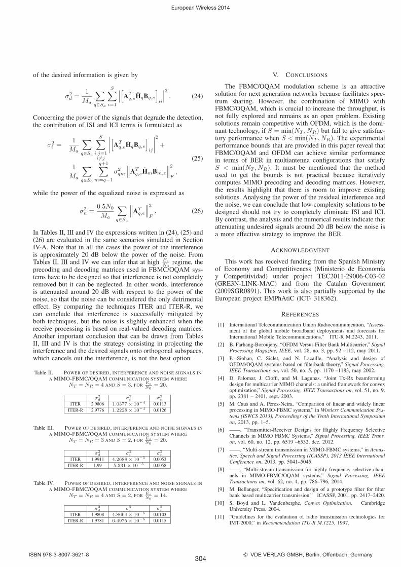
of the desired information is given by
σ2d =
1
Ma
∑q∈Sa
S∑i=1
∣∣∣[ATq,eHqBq,e
]ii
∣∣∣2 . (24)
Concerning the power of the signals that degrade the detection,the contribution of ISI and ICI terms is formulated as
σ2i =
1
Ma
∑q∈Sa
S∑i,j=1i �=j
∣∣∣∣[ATq,eHqBq,e
]ij
∣∣∣∣2
+
1
Ma
∑q∈Sa
q+1∑m=q−1
σ2qm
∥∥∥ATq,eHmBm,e
∥∥∥2F,
(25)
while the power of the equalized noise is expressed as
σ2n =
0.5N0
Ma
∑q∈Sa
∥∥∥ATq,e
∥∥∥2F. (26)
In Tables II, III and IV the expressions written in (24), (25) and(26) are evaluated in the same scenarios simulated in SectionIV-A. Note that in all the cases the power of the interferenceis approximately 20 dB below the power of the noise. FromTables II, III and IV we can infer that at high Es
N0regime, the
precoding and decoding matrices used in FBMC/OQAM sys-tems have to be designed so that interference is not completelyremoved but it can be neglected. In other words, interferenceis attenuated around 20 dB with respect to the power of thenoise, so that the noise can be considered the only detrimentaleffect. By comparing the techniques ITER and ITER-R, wecan conclude that interference is successfully mitigated byboth techniques, but the noise is slightly enhanced when thereceive processing is based on real-valued decoding matrices.Another important conclusion that can be drawn from TablesII, III and IV is that the strategy consisting in projecting theinterference and the desired signals onto orthogonal subspaces,which cancels out the interference, is not the best option.
Table II. POWER OF DESIRED, INTERFERENCE AND NOISE SIGNALS IN
A MIMO-FBMC/OQAM COMMUNICATION SYSTEM WHERE
NT = NR = 4 AND S = 3, FOR Es
N0= 20.
σ2d σ2
i σ2n
ITER 2.9806 1.0377× 10⁻⁴ 0.0113ITER-R 2.9776 1.2228× 10⁻⁴ 0.0126
Table III. POWER OF DESIRED, INTERFERENCE AND NOISE SIGNALS IN
A MIMO-FBMC/OQAM COMMUNICATION SYSTEM WHERE
NT = NR = 3 AND S = 2, FOR Es
N0= 20.
σ2d σ2
i σ2n
ITER 1.9911 4.2688× 10⁻⁵ 0.0053ITER-R 1.99 5.331× 10⁻⁵ 0.0058
Table IV. POWER OF DESIRED, INTERFERENCE AND NOISE SIGNALS IN
A MIMO-FBMC/OQAM COMMUNICATION SYSTEM WHERE
NT = NR = 4 AND S = 2, FOR Es
N0= 14.
σ2d σ2
i σ2n
ITER 1.9808 4.8664× 10⁻⁵ 0.0103ITER-R 1.9781 6.4975× 10⁻⁵ 0.0115
V. CONCLUSIONS
The FBMC/OQAM modulation scheme is an attractivesolution for next generation networks because facilitates spec-trum sharing. However, the combination of MIMO withFBMC/OQAM, which is crucial to increase the throughput, isnot fully explored and remains as an open problem. Existingsolutions remain competitive with OFDM, which is the domi-nant technology, if S = min(NT , NR) but fail to give satisfac-tory performance when S < min(NT , NR). The experimentalperformance bounds that are provided in this paper reveal thatFBMC/OQAM and OFDM can achieve similar performancein terms of BER in multiantenna configurations that satisfyS < min(NT , NR). It must be mentioned that the methodused to get the bounds is not practical because iterativelycomputes MIMO precoding and decoding matrices. However,the results highlight that there is room to improve existingsolutions. Analysing the power of the residual interference andthe noise, we can conclude that low-complexity solutions to bedesigned should not try to completely eliminate ISI and ICI.By contrast, the analysis and the numerical results indicate thatattenuating undesired signals around 20 dB below the noise isa more effective strategy to improve the BER.
ACKNOWLEDGMENT
This work has received funding from the Spanish Ministryof Economy and Competitiveness (Ministerio de Economıay Competitividad) under project TEC2011-29006-C03-02(GRE3N-LINK-MAC) and from the Catalan Government(2009SGR0891). This work is also partially supported by theEuropean project EMPhAtiC (ICT- 318362).
REFERENCES
[1] International Telecommunication Union Radiocommunication, “Assess-ment of the global mobile broadband deployments and forecasts forInternational Mobile Telecommunications.” ITU-R M.2243, 2011.
[2] B. Farhang-Boroujeny, “OFDM Versus Filter Bank Multicarrier,” SignalProcessing Magazine, IEEE, vol. 28, no. 3, pp. 92 –112, may 2011.
[3] P. Siohan, C. Siclet, and N. Lacaille, “Analysis and design ofOFDM/OQAM systems based on filterbank theory,” Signal Processing,IEEE Transactions on, vol. 50, no. 5, pp. 1170 –1183, may 2002.
[4] D. Palomar, J. Cioffi, and M. Lagunas, “Joint Tx-Rx beamformingdesign for multicarrier MIMO channels: a unified framework for convexoptimization,” Signal Processing, IEEE Transactions on, vol. 51, no. 9,pp. 2381 – 2401, sept. 2003.
[5] M. Caus and A. Perez-Neira, “Comparison of linear and widely linearprocessing in MIMO-FBMC systems,” in Wireless Communication Sys-tems (ISWCS 2013), Proceedings of the Tenth International Symposiumon, 2013, pp. 1–5.
[6] ——, “Transmitter-Receiver Designs for Highly Frequency SelectiveChannels in MIMO FBMC Systems,” Signal Processing, IEEE Trans.on, vol. 60, no. 12, pp. 6519 –6532, dec. 2012.
[7] ——, “Multi-stream transmission in MIMO-FBMC systems,” in Acous-tics, Speech and Signal Processing (ICASSP), 2013 IEEE InternationalConference on, 2013, pp. 5041–5045.
[8] ——, “Multi-stream transmission for highly frequency selective chan-nels in MIMO-FBMC/OQAM systems,” Signal Processing, IEEETransactions on, vol. 62, no. 4, pp. 786–796, 2014.
[9] M. Bellanger, “Specification and design of a prototype filter for filterbank based multicarrier transmission.” ICASSP, 2001, pp. 2417–2420.
[10] S. Boyd and L. Vandenberghe, Convex Optimization. CambridgeUniversity Press, 2004.
[11] “Guidelines for the evaluation of radio transmission technologies forIMT-2000,” in Recommendation ITU-R M.1225, 1997.
European Wireless 2014
304ISBN 978-3-8007-3621-8 © VDE VERLAG GMBH, Berlin, Offenbach, Germany


