0.6/1 kV PVC insulated, single core cables with copper ...
5
DIMENSION AND WEIGHTS ELECTRICAL PROPERTIES Nominal Cross Section Overall Diameter (approx) Net Weight (approx) Delivery Length DC Conductor Resistance at 20 ºC Max Current Carrying Capacity (A) mm ² mm kg/km m ohm/km In ground at 20 ºC In air at 30 ºC *** * ** *** * ** 0.6/1 kV PVC insulated, single core cables with copper conductor Construction 1 3 Solid or stranded copper conductor PVC outer jacket Code: YVV-U, YVV-R, CU/PVC/PVC,NYY U: Solid Conductor R: Stranded Conductor Rigid Standards: IEC 60502 - 1, VDE 0276 - 603 Technical Data Application Indoors and outdoors, in cable ducts, underground, in power or switching stations, local energy distributions, industrial plants, where there is no risk of mechanical damage. 2 PVC insulation Max. operating temperature : 70 °C Max. short circuit temperature : (max. 5 sec.) Rated voltage : 0.6/1 kV Min. bending radius : 12 x D D : Cable outer diameter 2 Cross section < 300 mm 2 Cross section > 300 mm : 140 °C : 160 °C 1 3 2 1x1,5 1x2,5 1x4 1x6 1x10 1x16 1x25 1x35 1x50 1x70 1x95 1x120 1x150 1x185 1x240 1x300 1x400 1x500 1x630 5,8 6,2 7,0 7,5 9,0 10,0 11,5 12,5 14,0 15,5 18,0 19,5 21,0 23,5 27,0 30,5 34,0 37,0 42,0 50 60 85 105 160 215 320 420 570 780 1050 1300 1600 1950 2550 3150 4200 5200 6450 1000 1000 1000 1000 1000 1000 1000 1000 1000 1000 1000 1000 1000 1000 1000 1000 1000 1000 500 12,1 7,41 4,61 3,08 1,83 1,15 0,727 0,524 0,387 0,268 0,193 0,153 0,124 0,0991 0,0754 0,0601 0,0470 0,0366 0,0283 - - - - - 127 163 195 230 282 336 382 428 483 561 632 730 823 866 30 39 50 62 83 107 137 165 195 239 287 326 366 414 481 542 624 698 775 25 34 45 57 78 103 137 169 206 261 321 374 428 494 590 678 817 940 1042 20 27 37 48 66 89 118 145 176 224 271 314 361 412 484 549 657 749 858 Note : Current carrying capacities are valid under the following conditions; In ground : 20 ºC, 70 cm depth of lay, soil-thermal resistivity 1 K.m/W, load factor 0.7 In air : 30 ºC, load factor 1.0 *** : Flat formation, clearance between cables; in air = 1 x Cable outer diameter, in ground = 7 cm : Trefoil formation Number of system : 1 * ** Installation Cables 19
Transcript of 0.6/1 kV PVC insulated, single core cables with copper ...

DIMENSION AND WEIGHTS ELECTRICAL PROPERTIES
Nominal Cross
Section
Overall Diameter (approx)
Net Weight (approx)
Delivery Length
DC Conductor Resistance at
20 ºC MaxCurrent Carrying Capacity (A)
mm ² mm kg/km m ohm/kmIn ground at 20 ºC In air at 30 ºC
*** ** * *** ** *
0.6/1 kV PVC insulated, single core cableswith copper conductor
Construction
1 3Solid or stranded copper conductor PVC outer jacket
Code: YVV-U, YVV-R, CU/PVC/PVC,NYY
U: Solid Conductor R: Stranded Conductor Rigid
Standards: IEC 60502 - 1, VDE 0276 - 603
Technical Data ApplicationIndoors and outdoors, in cable ducts, underground, in power or switching stations, local energy distributions, industrial plants, where there is no risk of mechanical damage.
2 PVC insulation
Max. operating temperature : 70 °CMax. short circuit temperature : (max. 5 sec.)
Rated voltage : 0.6/1 kVMin. bending radius : 12 x DD : Cable outer diameter
2Cross section < 300 mm2Cross section > 300 mm : 140 °C
: 160 °C
13 2
1x1,5
1x2,5
1x4
1x6
1x10
1x16
1x25
1x35
1x50
1x70
1x95
1x120
1x150
1x185
1x240
1x300
1x400
1x500
1x630
5,8
6,2
7,0
7,5
9,0
10,0
11,5
12,5
14,0
15,5
18,0
19,5
21,0
23,5
27,0
30,5
34,0
37,0
42,0
50
60
85
105
160
215
320
420
570
780
1050
1300
1600
1950
2550
3150
4200
5200
6450
1000
1000
1000
1000
1000
1000
1000
1000
1000
1000
1000
1000
1000
1000
1000
1000
1000
1000
500
12,1
7,41
4,61
3,08
1,83
1,15
0,727
0,524
0,387
0,268
0,193
0,153
0,124
0,0991
0,0754
0,0601
0,0470
0,0366
0,0283
-
-
-
-
-
127
163
195
230
282
336
382
428
483
561
632
730
823
866
30
39
50
62
83
107
137
165
195
239
287
326
366
414
481
542
624
698
775
25
34
45
57
78
103
137
169
206
261
321
374
428
494
590
678
817
940
1042
20
27
37
48
66
89
118
145
176
224
271
314
361
412
484
549
657
749
858
Note : Current carrying capacities are valid under the following conditions;In ground : 20 ºC, 70 cm depth of lay, soil-thermal resistivity 1 K.m/W, load factor 0.7In air : 30 ºC, load factor 1.0*** : Flat formation, clearance between cables; in air = 1 x Cable outer diameter, in ground = 7 cm : Trefoil formationNumber of system : 1
** *
Inst
alla
tio
n C
able
s
19
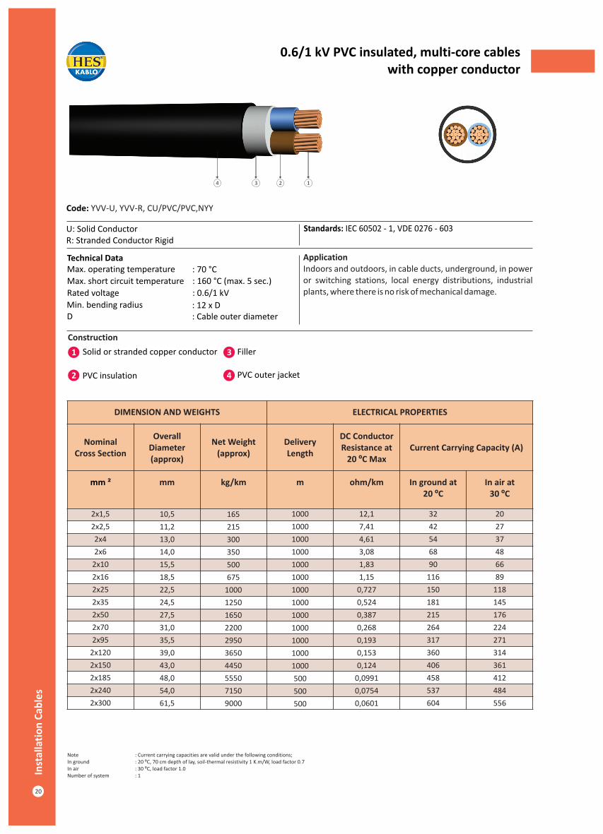
0.6/1 kV PVC insulated, multi-core cableswith copper conductor
Construction
1 3Solid or stranded copper conductor Filler
Code: YVV-U, YVV-R, CU/PVC/PVC,NYY
U: Solid Conductor R: Stranded Conductor Rigid
Standards: IEC 60502 - 1, VDE 0276 - 603
Technical DataMax. operating temperature : 70 °C Max. short circuit temperature : 160 °C (max. 5 sec.)
Rated voltage : 0.6/1 kV
ApplicationIndoors and outdoors, in cable ducts, underground, in power or switching stations, local energy distributions, industrial plants, where there is no risk of mechanical damage.
2 PVC insulation
Min. bending radius : 12 x DD : Cable outer diameter
4 PVC outer jacket
134 2
DIMENSION AND WEIGHTS ELECTRICAL PROPERTIES
Nominal Cross Section
Overall Diameter (approx)
Net Weight (approx)
Delivery Length
DC Conductor Resistance at
20 ºC MaxCurrent Carrying Capacity (A)
mm ² mm kg/km m ohm/km In ground at20 ºC
In air at 30 ºC
2x1,5
2x2,5
2x4
2x6
2x10
2x16
2x25
2x35
2x50
2x70
2x95
2x120
2x150
2x185
2x240
2x300
10,5
11,2
13,0
14,0
15,5
18,5
22,5
24,5
27,5
31,0
35,5
39,0
43,0
48,0
54,0
61,5
165
215
300
350
500
675
1000
1250
1650
2200
2950
3650
4450
5550
7150
9000
1000
1000
1000
1000
1000
1000
1000
1000
1000
1000
1000
1000
1000
500
500
500
12,1
7,41
4,61
3,08
1,83
1,15
0,727
0,524
0,387
0,268
0,193
0,153
0,124
0,0991
0,0754
0,0601
32
42
54
68
90
116
150
181
215
264
317
360
406
458
537
604
20
27
37
48
66
89
118
145
176
224
271
314
361
412
484
556
Note : Current carrying capacities are valid under the following conditions;In ground : 20 ºC, 70 cm depth of lay, soil-thermal resistivity 1 K.m/W, load factor 0.7In air : 30 ºC, load factor 1.0Number of system : 1Inst
alla
tio
n C
able
s
20

0.6/1 kV PVC insulated, multi-core cableswith copper conductor
Construction
Code: YVV-U, YVV-R, CU/PVC/PVC,NYY
U: Solid Conductor R: Stranded Conductor Rigid
Standards: IEC 60502 - 1, VDE 0276 - 603
Technical Data ApplicationIndoors and outdoors, in cable ducts, underground, in power or switching stations, local energy distributions, industrial plants, where there is no risk of mechanical damage.
Max. operating temperature : 70 °CMax. short circuit temperature : (max. 5 sec.)
Rated voltage : 0.6/1 kVMin. bending radius : 12 x DD : Cable outer diameter
2Cross section < 300 mm2Cross section > 300 mm : 140 °C
: 160 °C
1 3Solid or stranded copper conductor Filler
2 PVC insulation 4 PVC outer jacket
14 3 2
DIMENSION AND WEIGHTS ELECTRICAL PROPERTIES
Nominal Cross Section
Overall Diameter (approx)
Net Weight (approx)
Delivery Length
DC Conductor Resistance at
20 ºC MaxCurrent Carrying Capacity (A)
mm ² mm kg/km m ohm/kmIn ground at
20 ºCIn air at
30 ºC
3x1,5
3x2,5
3x4
3x6
3x10
3x16
3x25
3x35
3x50
3x70
3x95
3x120
3x150
3x185
3x240
3x300
3x400
11,0
11,8
13,6
15,5
17,5
19,5
24,0
26,0
29,5
33,5
38,0
42,0
46,0
51,0
58,0
65,0
71,0
200
230
340
425
620
835
1250
1600
2100
2900
3900
4800
5900
7300
9450
11800
15500
1000
1000
1000
1000
1000
1000
1000
1000
1000
1000
1000
1000
500
500
500
250
250
12,1
7,41
4,61
3,08
1,83
1,15
0,727
0,524
0,387
0,268
0,193
0,153
0,124
0,0991
0,0754
0,0601
0,0470
26
34
44
56
75
98
128
157
185
228
275
313
353
399
464
524
600
18.5
25
34
43
60
80
106
131
159
202
244
282
324
371
436
481
560
Note : Current carrying capacities are valid under the following conditions;In ground : 20 ºC, 70 cm depth of lay, soil-thermal resistivity 1 K.m/W, load factor 0.7In air : 30 ºC, load factor 1.0Number of system : 1 P
VC
Insu
late
d L
ow
Vo
ltag
e C
able
s
21

0.6/1 kV PVC insulated, multi-core cableswith copper conductor
Construction
1 3Stranded copper conductor Filler
Code: YVV-R, CU/PVC/PVC,NYY
R: Stranded Conductor Rigid Standards: IEC 60502 - 1, VDE 0276 - 603
Technical Data ApplicationIndoors and outdoors, in cable ducts, underground, in power or switching stations, local energy distributions, industrial plants, where there is no risk of mechanical damage.
2 PVC insulation 4 PVC outer jacket
Max. operating temperature : 70 °CMax. short circuit temperature : (max. 5 sec.)
Rated voltage : 0.6/1 kVMin. bending radius : 12 x DD : Cable outer diameter
2Cross section < 300 mm2Cross section > 300 mm : 140 °C
: 160 °C
134 2
DIMENSION AND WEIGHTS ELECTRICAL PROPERTIES
Nominal Cross Section
Overall Diameter (approx)
Net Weight (approx)
Delivery Length
DC Conductor Resistance at
20 ºC MaxCurrent Carrying Capacity (A)
mm ² mm kg/km m ohm/kmIn ground at
20 ºCIn air at
30 ºC
3x16+10
3x25+16
3x35+16
3x50+25
3x70+35
3x95+50
3x120+70
3x150+70
3x185+95
3x240+120
3x300+150
3x400+185
21,5
25,0
27,0
31,0
35,0
40,0
44,5
48,0
53,0
60,5
68,0
76,0
970
1400
1750
2400
3300
4400
5550
6550
8200
10600
13100
17000
1000
1000
1000
1000
1000
1000
500
500
500
500
250
250
1,15
0,727
0,524
0,387
0,268
0,193
0,153
0,124
0,0991
0,0754
0,0601
0,0470
98
128
157
185
228
275
313
353
399
464
524
600
80
106
131
159
202
244
282
324
371
436
481
560
Note : Current carrying capacities are valid under the following conditions;In ground : 20 ºC, 70 cm depth of lay, soil-thermal resistivity 1 K.m/W, load factor 0.7In air : 30 ºC, load factor 1.0Number of system : 1Inst
alla
tio
n C
able
s
22

0.6/1 kV PVC insulated, multi-core cableswith copper conductor
Construction
Code: YVV-U, YVV-R, CU/PVC/PVC,NYY
U: Solid Conductor R: Stranded Conductor Rigid
Standards: IEC 60502 - 1, VDE 0276 - 603
Technical Data ApplicationIndoors and outdoors, in cable ducts, underground, in power or switching stations, local energy distributions, industrial plants, where there is no risk of mechanical damage.
Max. operating temperature : 70 °C Max. short circuit temperature : (max. 5 sec.)
Rated voltage : 0.6/1 kVMin. bending radius : 12 x DD : Cable outer diameter
2Cross section < 300 mm2Cross section > 300 mm : 140/1 kV
: 160/1 kV
1 3Solid or stranded copper conductor Filler
2 PVC insulation 4 PVC outer jacket
134 2
DIMENSION AND WEIGHTS ELECTRICAL PROPERTIES
Nominal Cross Section
Overall Diameter (approx)
Net Weight (approx)
Delivery Length
DC Conductor Resistance at
20 ºC MaxCurrent Carrying Capacity (A)
mm ² mm kg/km m ohm/kmIn ground at
20 ºCIn air at
30 ºC
4x1,5
4x2,5
4x4
4x6
4x10
4x16
4x25
4x35
4x50
4x70
4x95
4x120
4x150
4x185
4x240
4x300
4x400
11,6
12,6
14,8
16,0
18,0
21,5
26,0
28,5
33,0
37,5
42,5
46,5
51,5
57,0
65,0
73,0
79,0
235
270
400
520
690
1050
1550
2000
2750
3750
5000
6200
7600
9450
12200
15200
19500
1000
1000
1000
1000
1000
1000
1000
1000
1000
1000
1000
500
500
500
500
250
250
12,1
7,41
4,61
3,08
1,83
1,15
0,727
0,524
0,387
0,268
0,193
0,153
0,124
0,0991
0,0754
0,0601
0,0470
26
34
44
56
75
98
128
157
185
228
275
313
353
399
464
524
600
18.5
25
34
43
60
80
106
131
159
202
244
282
324
371
436
481
560
Note : Current carrying capacities are valid under the following conditions;In ground : 20 ºC, 70 cm depth of lay, soil-thermal resistivity 1 K.m/W, load factor 0.7In air : 30 ºC, load factor 1.0Number of system : 1 P
VC
Insu
late
d L
ow
Vo
ltag
e C
able
s
23