06-Iron (Fe) - Iron Carbide(Fe3C) Phase Diagram
42
CHAPTER 6 Iron (Fe) - Iron Carbide(Fe 3 C) Phase Diagram Dr. Talaat El-Benawy
-
Upload
talaat-ahmed-mohamed-el-benawy -
Category
Documents
-
view
250 -
download
15
description
Fe-C
Transcript of 06-Iron (Fe) - Iron Carbide(Fe3C) Phase Diagram
CHAPTER 6
Iron (Fe) - Iron Carbide(Fe3C) Phase Diagram
Dr. Talaat El-Benawy
Introduction• The study of Fe-F3C alloying system is important because
it forms the basis of commercial steels and cast irons.Moreover, the basic features of this system influence thebehaviour of the most complex alloy steels
• Carbon is the most important alloying element in iron,which significantly affects the allotropy , structure andproperties of iron
• Conventionally, the complete Fe-C diagram should extendfrom 100% Fe to 100% carbon but it is normally studied upto around 6.67% carbon, because iron alloys of practicalindustrial importance contain not more than 4.5-5.0 %carbon
• Therefore, this diagram is is usually called Fe-Fe3Cequilibrium phase diagram
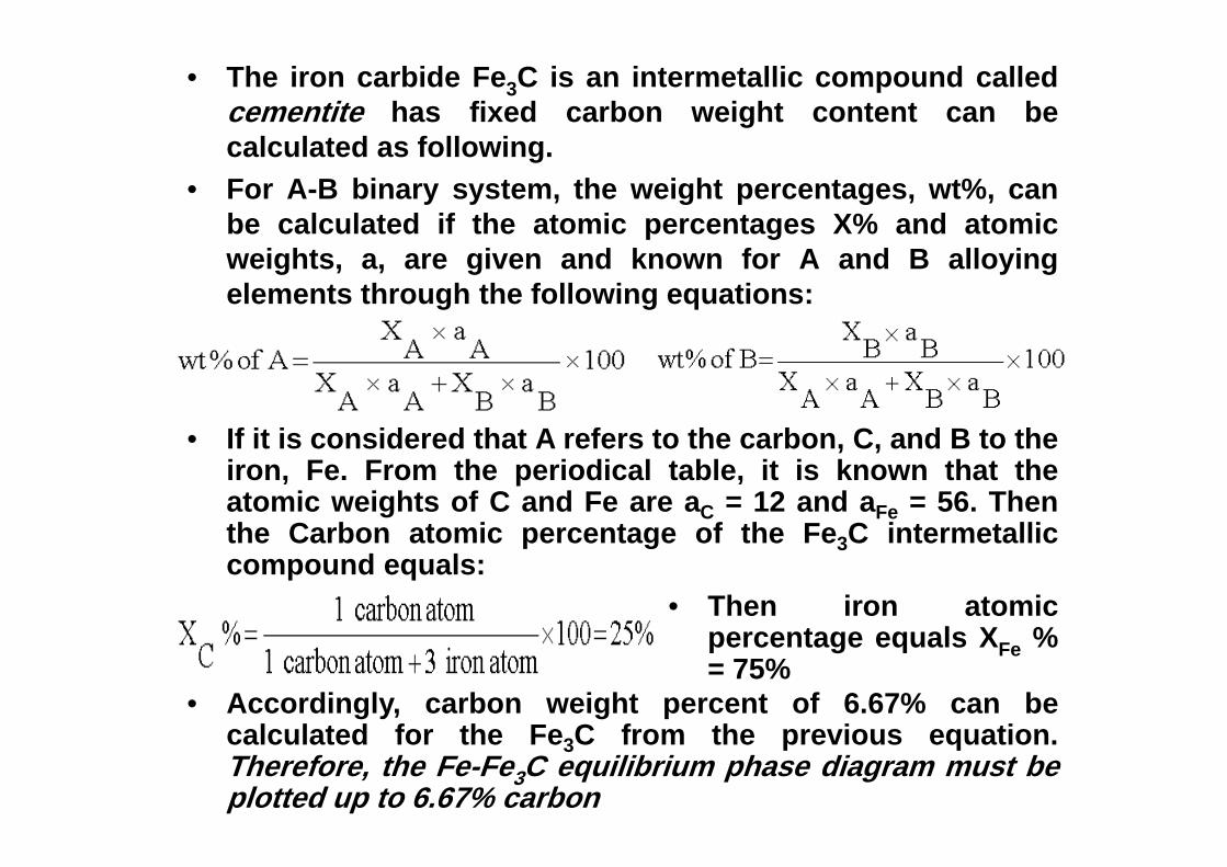
• The iron carbide Fe3C is an intermetallic compound calledcementite has fixed carbon weight content can becalculated as following.
• For A-B binary system, the weight percentages, wt%, canbe calculated if the atomic percentages X% and atomicweights, a, are given and known for A and B alloyingelements through the following equations:
• If it is considered that A refers to the carbon, C, and B to theiron, Fe. From the periodical table, it is known that theatomic weights of C and Fe are aC = 12 and aFe = 56. Thenthe Carbon atomic percentage of the Fe3C intermetalliccompound equals:
• Then iron atomicpercentage equals XFe %= 75%
• Accordingly, carbon weight percent of 6.67% can becalculated for the Fe3C from the previous equation.Therefore, the Fe-Fe3C equilibrium phase diagram must beplotted up to 6.67% carbon
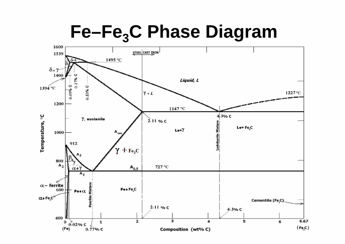
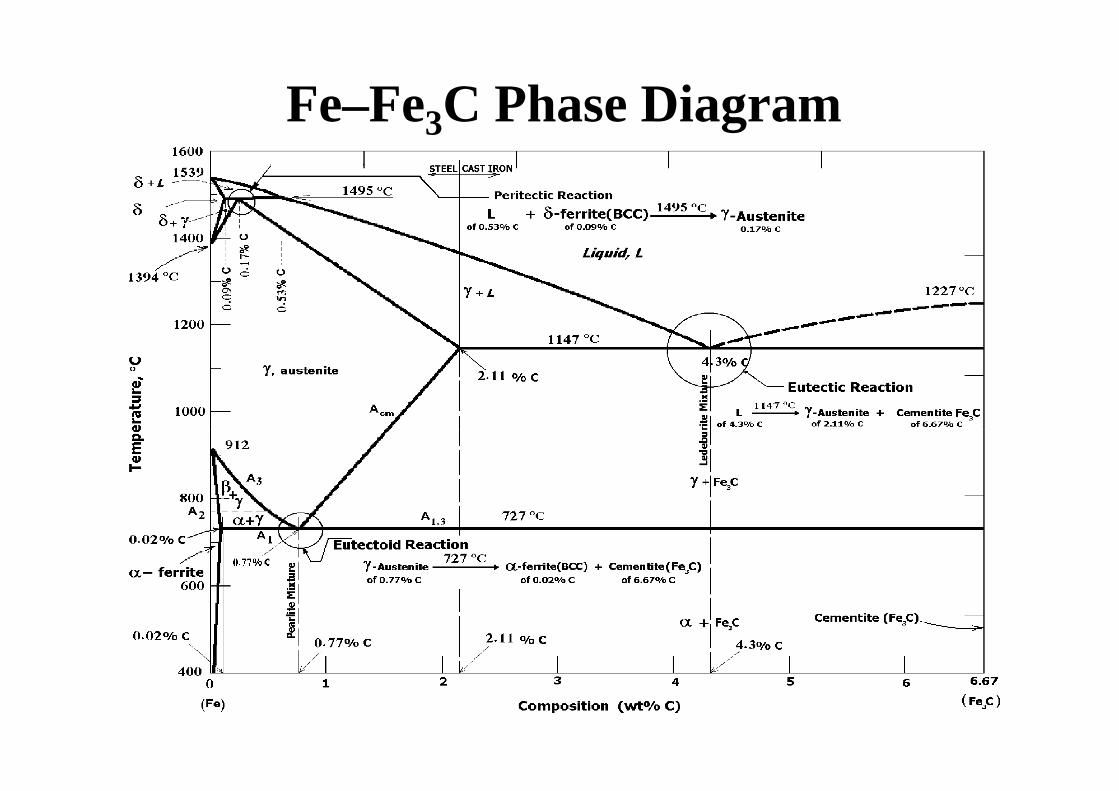
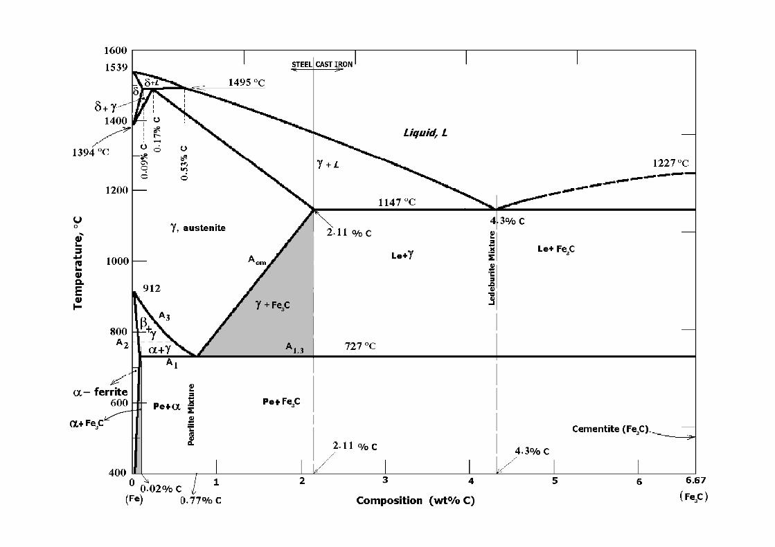
Fe–Fe3C Phase Diagram
Phases in Fe–Fe3C Phase Diagram
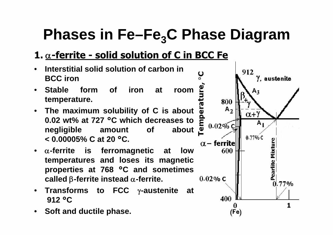
• Interstitial solid solution of carbon in BCC iron
• Stable form of iron at roomtemperature.
• The maximum solubility of C is about0.02 wt% at 727 °C which decreases tonegligible amount of about< 0.00005% C at 20 °C.
• -ferrite is ferromagnetic at lowtemperatures and loses its magneticproperties at 768 °C and sometimescalled -ferrite instead -ferrite.
• Transforms to FCC -austenite at912 °C
• Soft and ductile phase.
1. -ferrite - solid solution of C in BCC Fe
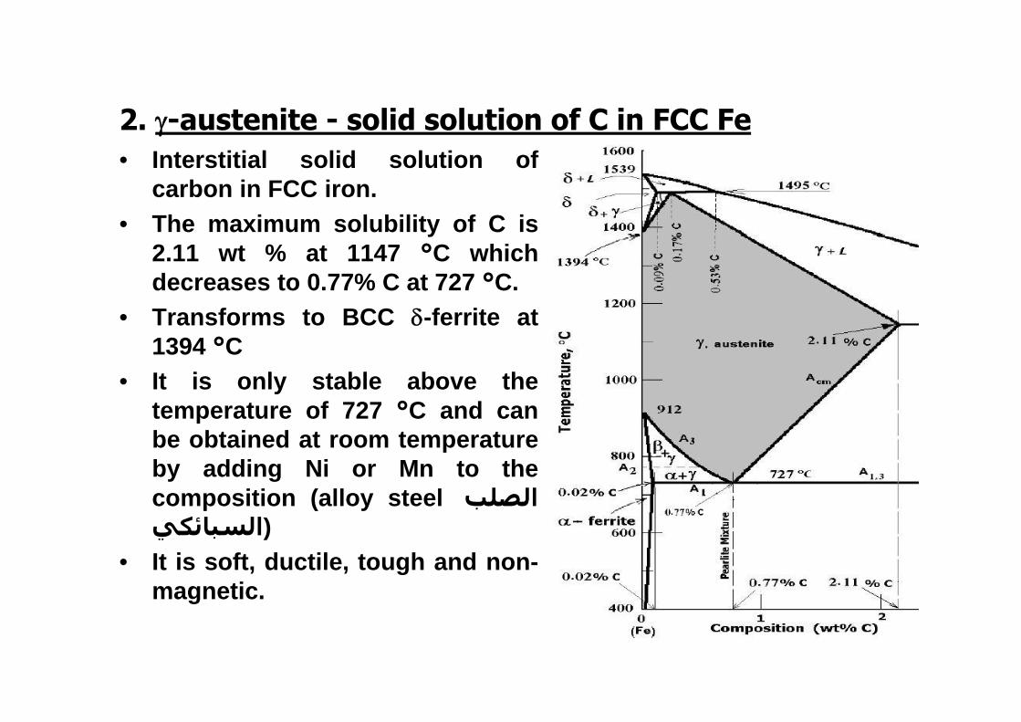
• Interstitial solid solution ofcarbon in FCC iron.
• The maximum solubility of C is2.11 wt % at 1147 °C whichdecreases to 0.77% C at 727 °C.
• Transforms to BCC -ferrite at1394 °C
• It is only stable above thetemperature of 727 °C and canbe obtained at room temperatureby adding Ni or Mn to thecomposition (alloy steel الصلب(السبائكي
• It is soft, ductile, tough and non-magnetic.
2. -austenite - solid solution of C in FCC Fe
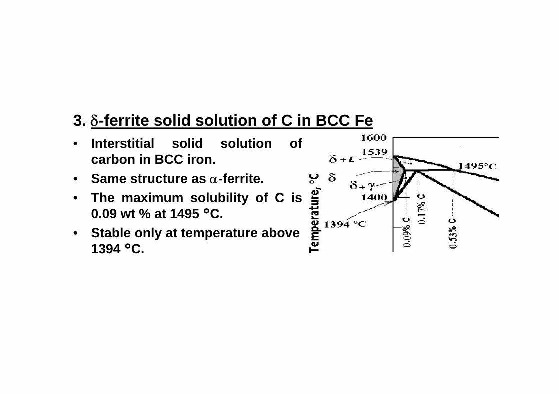
3. -ferrite solid solution of C in BCC Fe• Interstitial solid solution of
carbon in BCC iron.• Same structure as -ferrite.• The maximum solubility of C is
0.09 wt % at 1495 °C.• Stable only at temperature above
1394 °C.
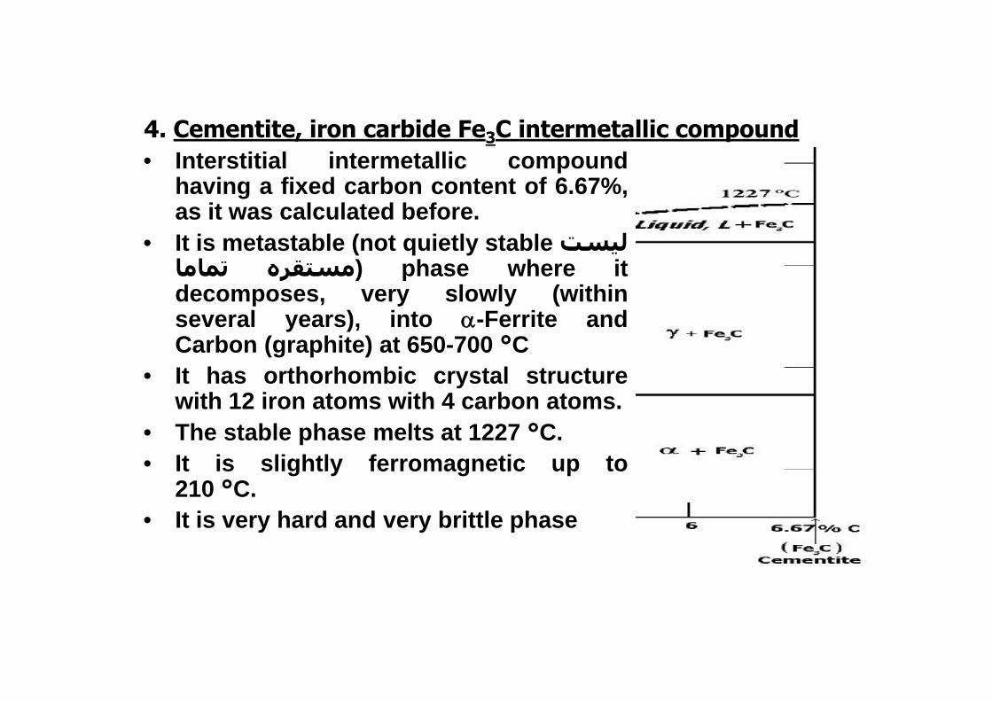
• Interstitial intermetallic compoundhaving a fixed carbon content of 6.67%,as it was calculated before.
• It is metastable (not quietly stable ليستتماما مستقره ) phase where it
decomposes, very slowly (withinseveral years), into -Ferrite andCarbon (graphite) at 650-700 °C
• It has orthorhombic crystal structurewith 12 iron atoms with 4 carbon atoms.
• The stable phase melts at 1227 °C.• It is slightly ferromagnetic up to
210 °C.• It is very hard and very brittle phase
4. Cementite, iron carbide Fe3C intermetallic compound
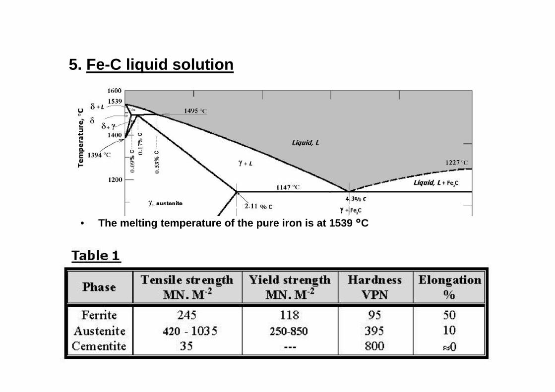
5. Fe-C liquid solution
• The melting temperature of the pure iron is at 1539 °C
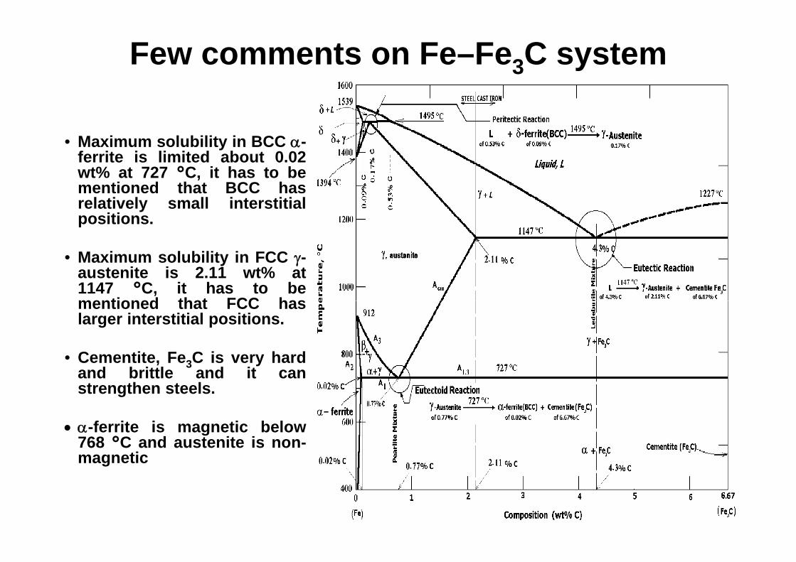
Few comments on Fe–Fe3C system
• Maximum solubility in BCC -ferrite is limited about 0.02wt% at 727 °C, it has to bementioned that BCC hasrelatively small interstitialpositions.
• Maximum solubility in FCC -austenite is 2.11 wt% at1147 °C, it has to bementioned that FCC haslarger interstitial positions.
• Cementite, Fe3C is very hardand brittle and it canstrengthen steels.
-ferrite is magnetic below768 °C and austenite is non-magnetic
Classification of the Fe-Fe3C phase diagram
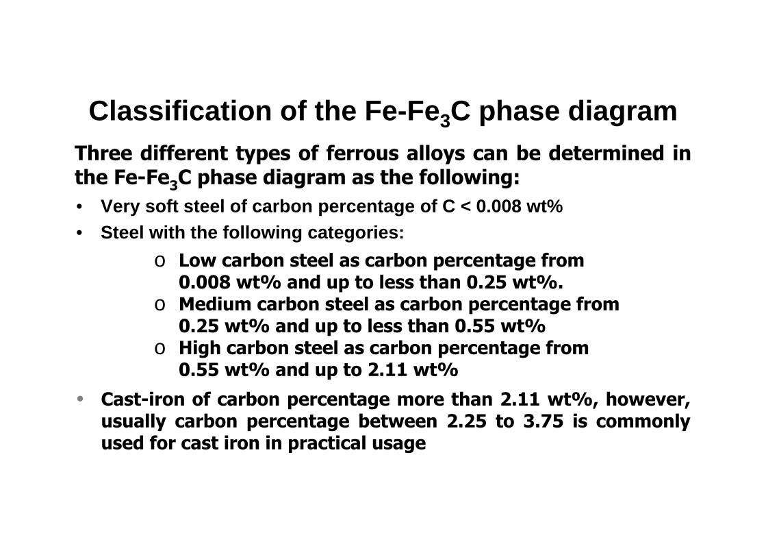
• Very soft steel of carbon percentage of C < 0.008 wt%• Steel with the following categories:
Three different types of ferrous alloys can be determined inthe Fe-Fe3C phase diagram as the following:
o Low carbon steel as carbon percentage from 0.008 wt% and up to less than 0.25 wt%.
o Medium carbon steel as carbon percentage from 0.25 wt% and up to less than 0.55 wt%
o High carbon steel as carbon percentage from 0.55 wt% and up to 2.11 wt%
• Cast-iron of carbon percentage more than 2.11 wt%, however,usually carbon percentage between 2.25 to 3.75 is commonlyused for cast iron in practical usage
Important Reactions in Fe-Fe3C equilibrium phase diagram
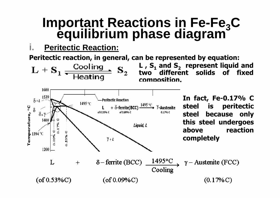
i. Peritectic Reaction: Peritectic reaction, in general, can be represented by equation:
L , S1 and S2 represent liquid andtwo different solids of fixedcomposition.
In fact, Fe-0.17% Csteel is peritecticsteel because onlythis steel undergoesabove reactioncompletely
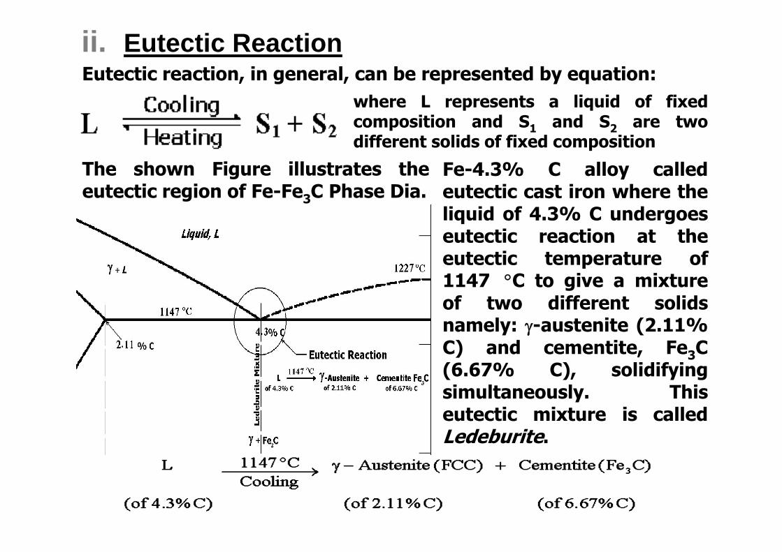
ii. Eutectic ReactionEutectic reaction, in general, can be represented by equation:
where L represents a liquid of fixedcomposition and S1 and S2 are twodifferent solids of fixed composition
The shown Figure illustrates theeutectic region of Fe-Fe3C Phase Dia.
Fe-4.3% C alloy calledeutectic cast iron where theliquid of 4.3% C undergoeseutectic reaction at theeutectic temperature of1147 C to give a mixtureof two different solidsnamely: -austenite (2.11%C) and cementite, Fe3C(6.67% C), solidifyingsimultaneously. Thiseutectic mixture is calledLedeburite.
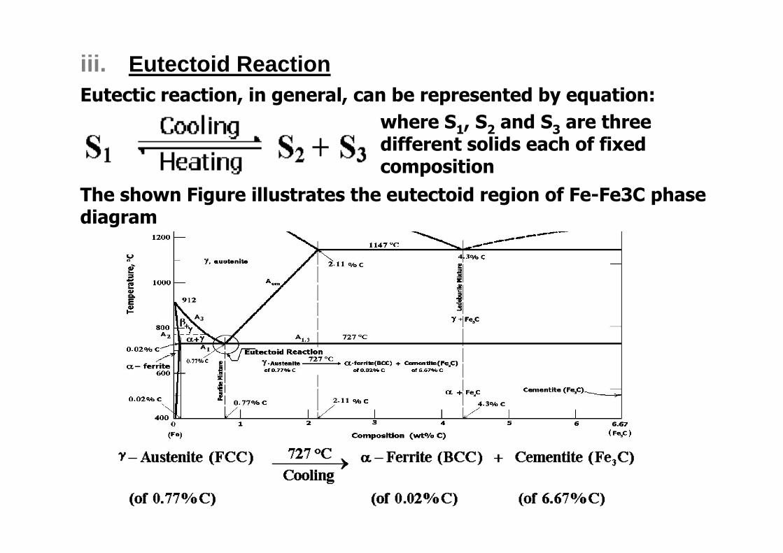
iii. Eutectoid ReactionEutectic reaction, in general, can be represented by equation:
where S1, S2 and S3 are three different solids each of fixed composition
The shown Figure illustrates the eutectoid region of Fe-Fe3C phase diagram
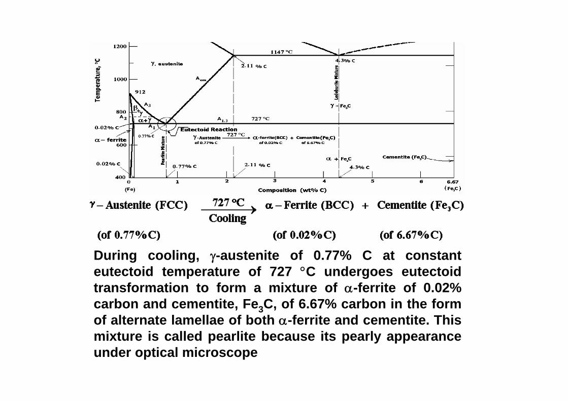
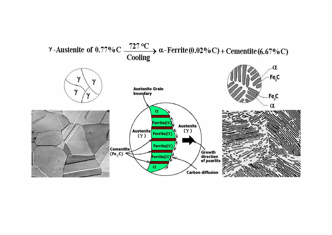
During cooling, -austenite of 0.77% C at constanteutectoid temperature of 727 C undergoes eutectoidtransformation to form a mixture of -ferrite of 0.02%carbon and cementite, Fe3C, of 6.67% carbon in the formof alternate lamellae of both -ferrite and cementite. Thismixture is called pearlite because its pearly appearanceunder optical microscope
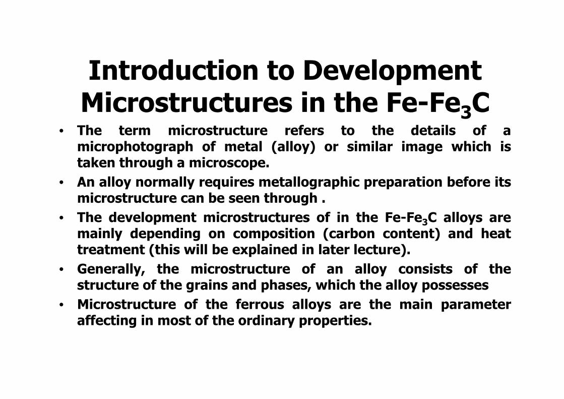
Introduction to Development Microstructures in the Fe-Fe3C
• The term microstructure refers to the details of amicrophotograph of metal (alloy) or similar image which istaken through a microscope.
• An alloy normally requires metallographic preparation before itsmicrostructure can be seen through .
• The development microstructures of in the Fe-Fe3C alloys aremainly depending on composition (carbon content) and heattreatment (this will be explained in later lecture).
• Generally, the microstructure of an alloy consists of thestructure of the grains and phases, which the alloy possesses
• Microstructure of the ferrous alloys are the main parameteraffecting in most of the ordinary properties.
Fe–Fe3C Phase Diagram
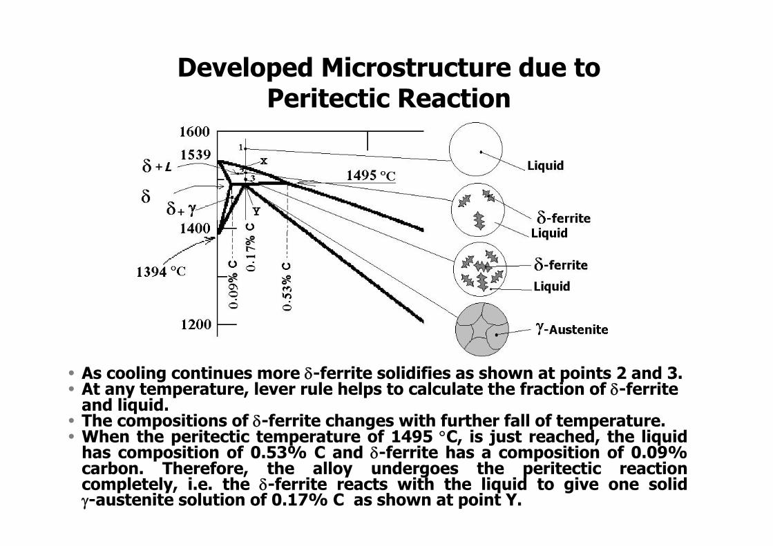
Developed Microstructure due toPeritectic Reaction
• As cooling continues more -ferrite solidifies as shown at points 2 and 3.• At any temperature, lever rule helps to calculate the fraction of -ferrite
and liquid.• The compositions of -ferrite changes with further fall of temperature.• When the peritectic temperature of 1495 C, is just reached, the liquid
has composition of 0.53% C and -ferrite has a composition of 0.09%carbon. Therefore, the alloy undergoes the peritectic reactioncompletely, i.e. the -ferrite reacts with the liquid to give one solid-austenite solution of 0.17% C as shown at point Y.
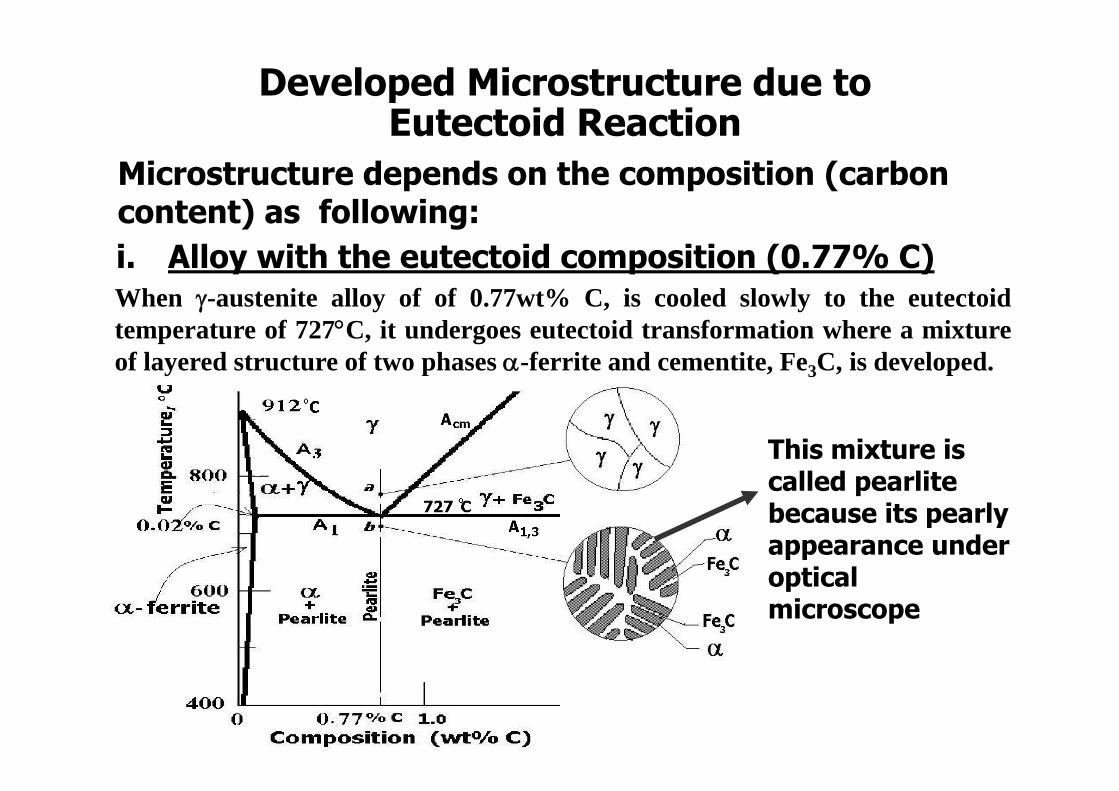
When -austenite alloy of of 0.77wt% C, is cooled slowly to the eutectoidtemperature of 727C, it undergoes eutectoid transformation where a mixtureof layered structure of two phases -ferrite and cementite, Fe3C, is developed.
Developed Microstructure due toEutectoid Reaction
This mixture is called pearlite because its pearly appearance under optical microscope
Microstructure depends on the composition (carbon content) as following:i. Alloy with the eutectoid composition (0.77% C)
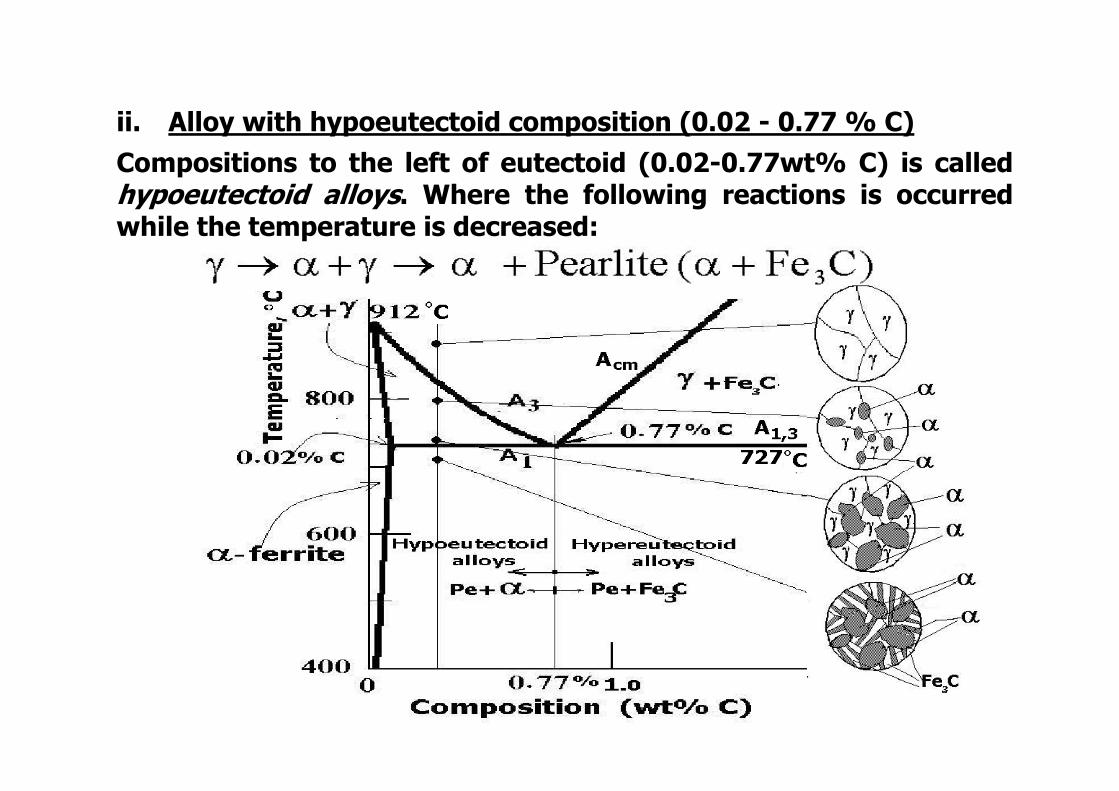
ii. Alloy with hypoeutectoid composition (0.02 - 0.77 % C)Compositions to the left of eutectoid (0.02-0.77wt% C) is calledhypoeutectoid alloys. Where the following reactions is occurredwhile the temperature is decreased:
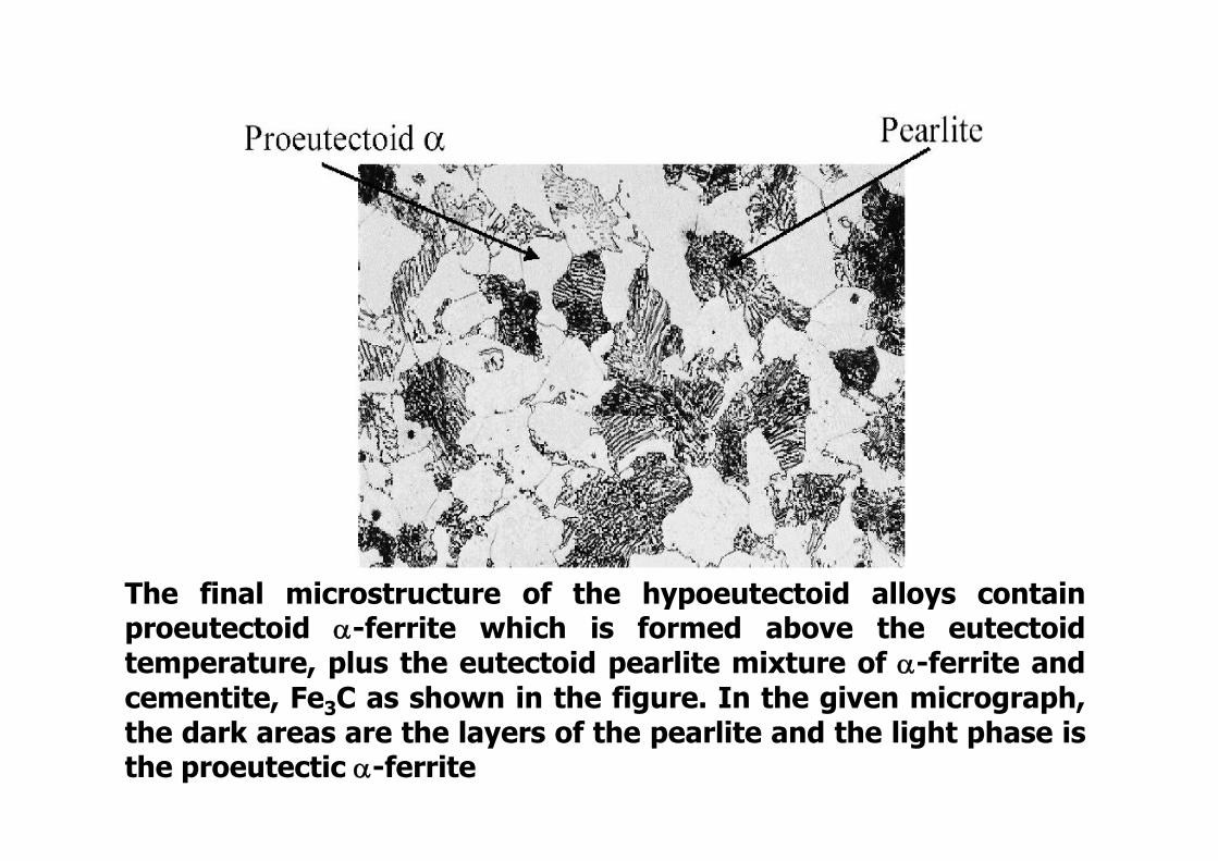
The final microstructure of the hypoeutectoid alloys containproeutectoid -ferrite which is formed above the eutectoidtemperature, plus the eutectoid pearlite mixture of -ferrite andcementite, Fe3C as shown in the figure. In the given micrograph,the dark areas are the layers of the pearlite and the light phase isthe proeutectic -ferrite
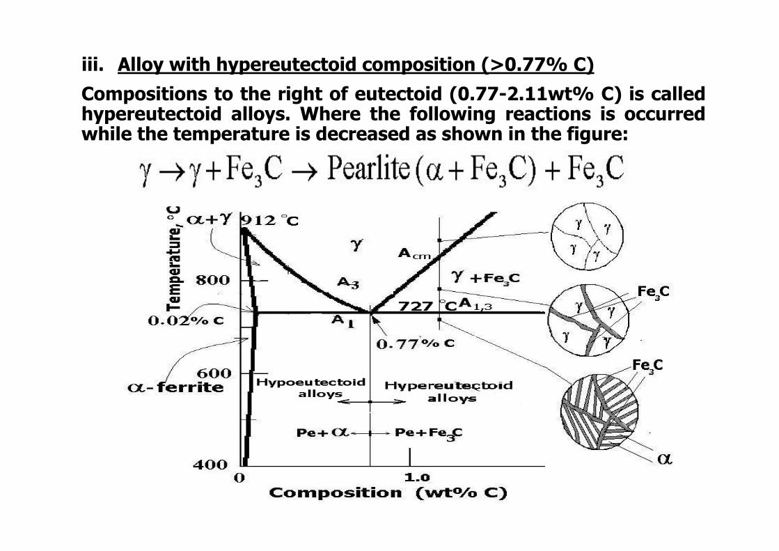
Compositions to the right of eutectoid (0.77-2.11wt% C) is calledhypereutectoid alloys. Where the following reactions is occurredwhile the temperature is decreased as shown in the figure:
iii. Alloy with hypereutectoid composition (>0.77% C)
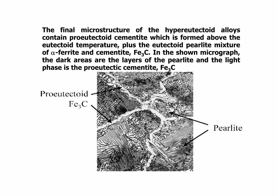
The final microstructure of the hypereutectoid alloyscontain proeutectoid cementite which is formed above theeutectoid temperature, plus the eutectoid pearlite mixtureof -ferrite and cementite, Fe3C. In the shown micrograph,the dark areas are the layers of the pearlite and the lightphase is the proeutectic cementite, Fe3C
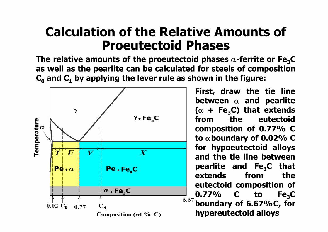
Calculation of the Relative Amounts of Proeutectoid Phases
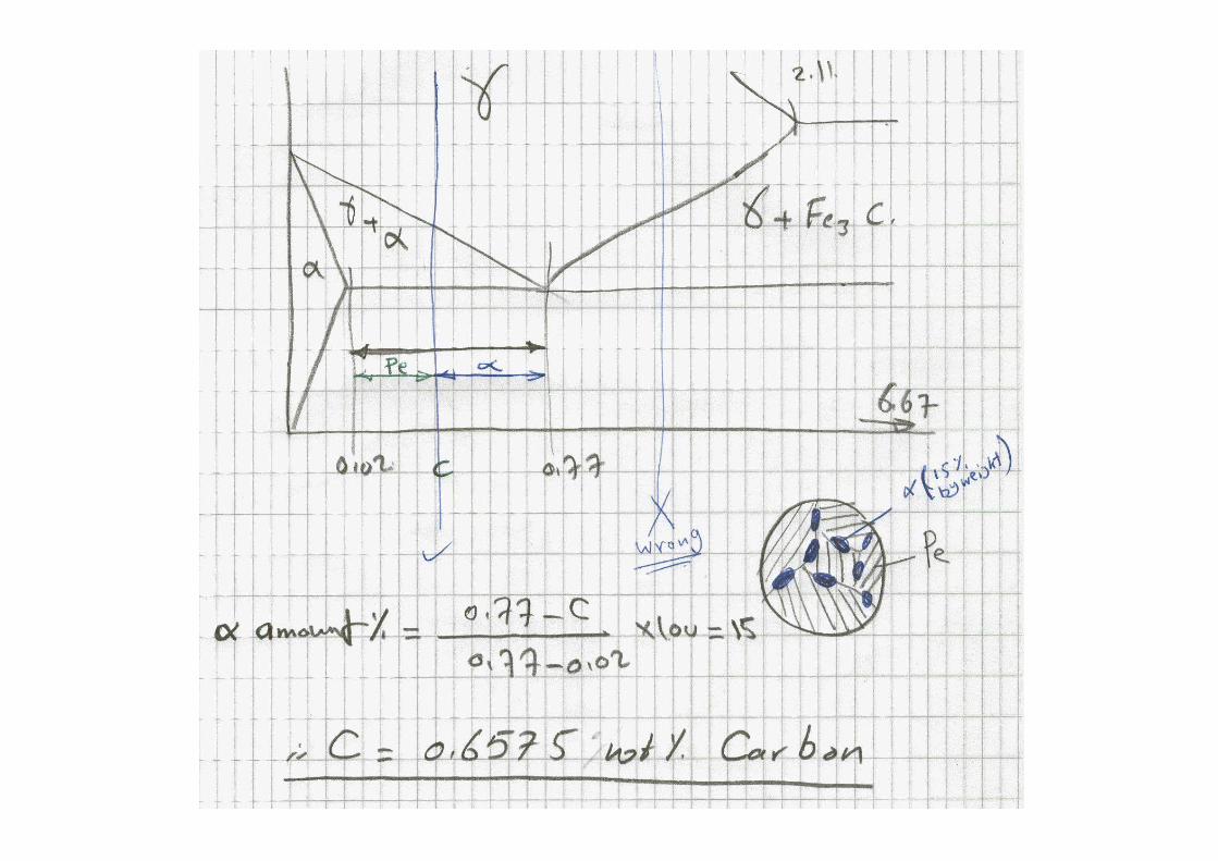
The relative amounts of the proeutectoid phases -ferrite or Fe3Cas well as the pearlite can be calculated for steels of compositionC0 and C1 by applying the lever rule as shown in the figure:
First, draw the tie linebetween and pearlite( + Fe3C) that extendsfrom the eutectoidcomposition of 0.77% Cto boundary of 0.02% Cfor hypoeutectoid alloysand the tie line betweenpearlite and Fe3C thatextends from theeutectoid composition of0.77% C to Fe3Cboundary of 6.67%C, forhypereutectoid alloys
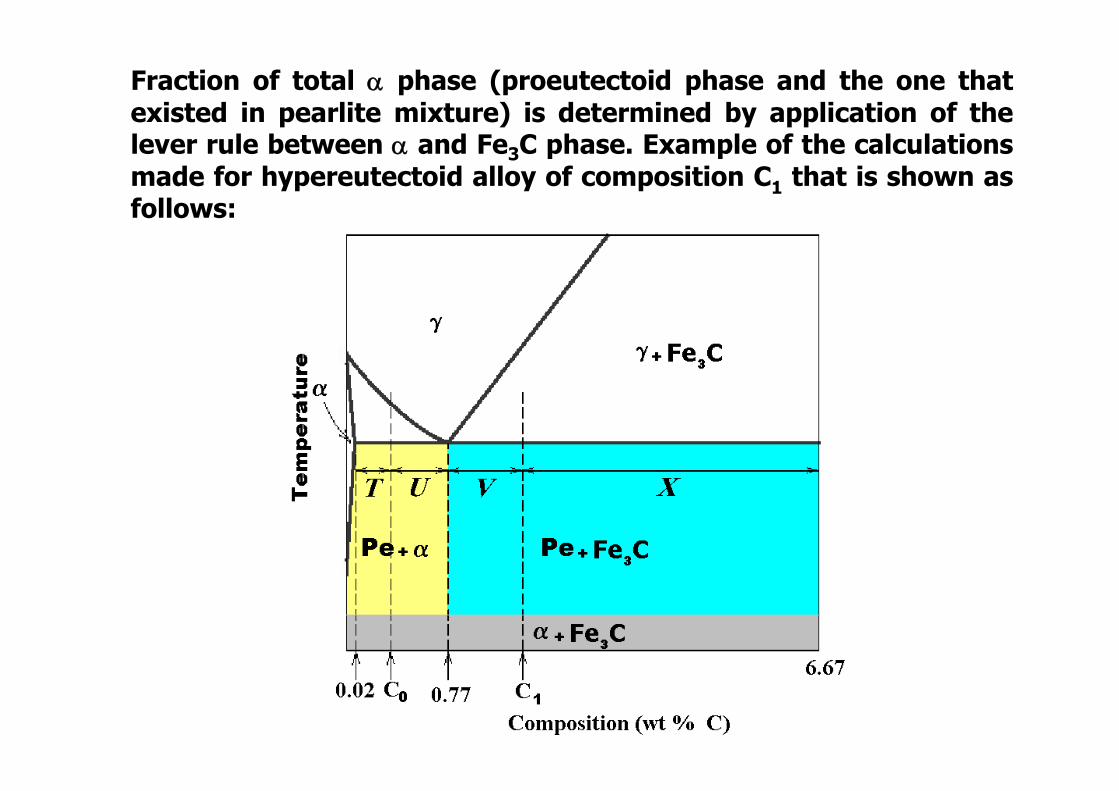
Fraction of total phase (proeutectoid phase and the one thatexisted in pearlite mixture) is determined by application of thelever rule between and Fe3C phase. Example of the calculationsmade for hypereutectoid alloy of composition C1 that is shown asfollows:
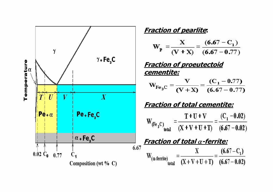
Fraction of pearlite:
Fraction of proeutectoidcementite:
Fraction of total -ferrite:
Fraction of total cementite:
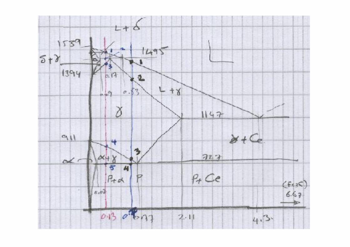
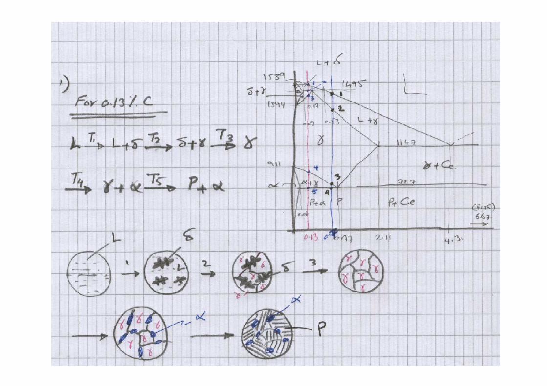
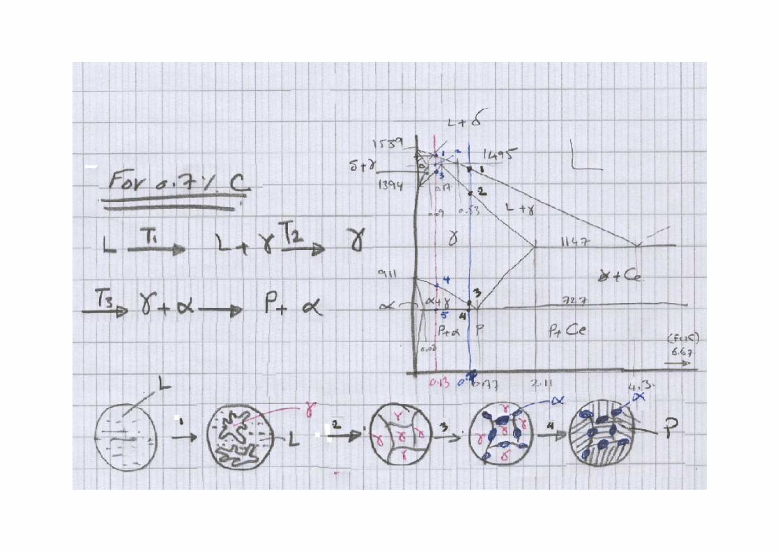
Problem 1Determine and show the transformationexperienced by slowly cooling plain carbonsteel containing 0.13% C and 0.7% from theliquid stat to -austenite phase.
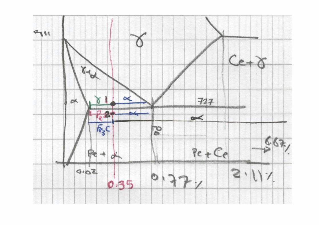
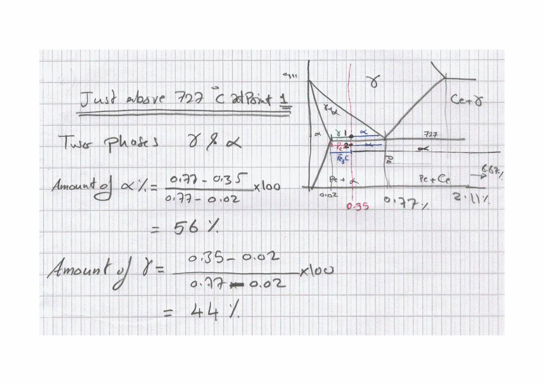
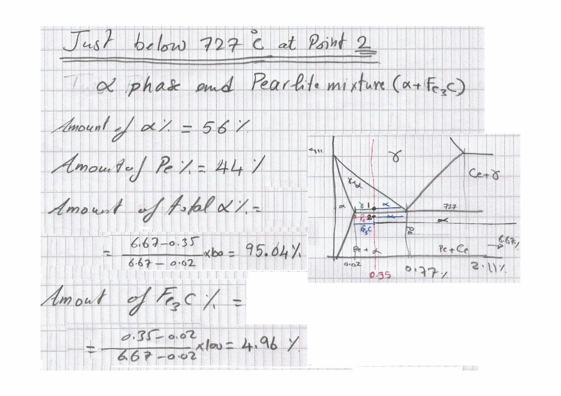
Problem 2Determine and calculate the amounts ofphases in Fe-0.35% C alloy just above and justbelow 727 C. For the same alloy calculate thetotal amount of the existed phases below727 C
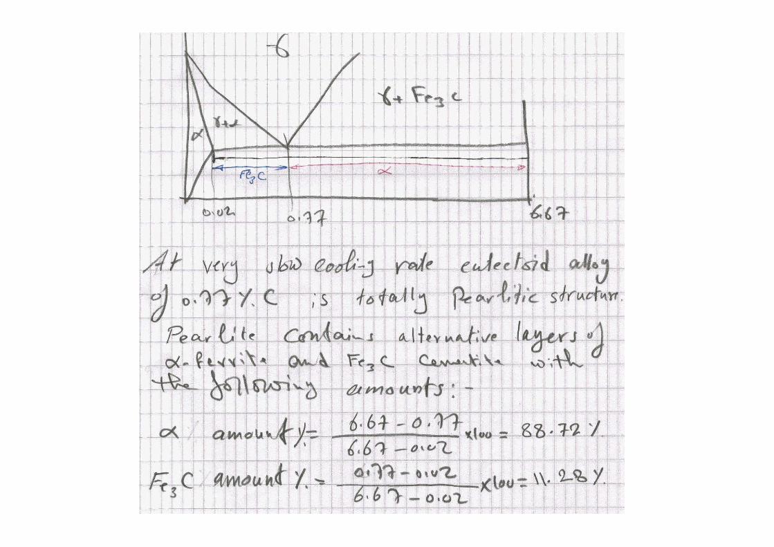
Problem 3Calculate the amounts of -ferrite andcementite phases in pearlite mixture of theeutectoid alloy
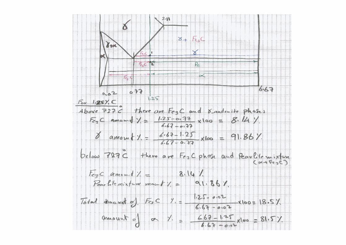
Problem 4Determine and calculate the amounts ofphases in Fe-1.25% C alloy just above and justbelow the eutectoid temperature (727 C)
Problem 5Slowly cooled plain carbon steel showsproeutectoid ferrite to be 15% by the weight ofthe microstructure. Estimate the carbonpercent of the steel