06 - Chemical Injection Pumps
5
CHEMICAL INJECTION PUMP PROCEDURES Review Date: March 6, 2006 Reviewed By: E.Vokes Section: Lonkar Well Testing Ltd. Procedures Subject: Chemical Injection Pumps Procedures Purpose: Chemical injection pumps are a simple pneumatic device which can utilize a wide range of supply pressures to pump chemical. • Potential Hazards: • Pressure release • Gas release • Chemical spray • Injection line parting • Environmental damage Action: Information: 1 Inspect Injection pump and make sure all regulators and gauges are in place. 1 This will ensure the pump does not get over pressured and have adequate supplied pressure. 2 Make sure lubricating oil is on the plunger shaft and should be topped periodically.(NOTE) If it is a oil less, do not fill reservoir with oil, 2 This will ensure that all mechanical parts do not rust. (NOTE) oil less has a flat box actuator. 3 Connect suction line to a filter to keep sand and grease out of the check valves. 3 This will keep all sand and oil from plugging your check valves. 4 Make sure all methanol and chemical is clean before rigging in suction line. 4 This will ensure that check valves will continue to be clean when injecting. 5 Connect the discharge line and follow the fill line for chemical pump procedure. 5 This will guide you on proper filling lines and prevents hose damage. 6 (Note) The use of Daniels grease is not recommended to be used in the Grease Jack Assembly. 6 The proper grease is TA-3179, Daniels grease breaks down and plugs the check valves.
description
Operator surface well test6
Transcript of 06 - Chemical Injection Pumps

CHEMICAL INJECTION PUMP PROCEDURES
Review Date: March 6, 2006
Reviewed By: E.Vokes
Section:
Lonkar Well Testing Ltd.
Procedures Subject: Chemical Injection Pumps Procedures
Purpose:
Chemical injection pumps are a simple pneumatic device which can utilize a wide range of supply pressures to pump chemical.
• Potential Hazards:
• Pressure release • Gas release • Chemical spray • Injection line parting • Environmental damage
Action: Information: 1 Inspect Injection pump and make sure all
regulators and gauges are in place. 1 This will ensure the pump does not get over
pressured and have adequate supplied pressure.
2 Make sure lubricating oil is on the plunger shaft and should be topped periodically.(NOTE) If it is a oil less, do not fill reservoir with oil,
2 This will ensure that all mechanical parts do not rust. (NOTE) oil less has a flat box actuator.
3 Connect suction line to a filter to keep sand and grease out of the check valves.
3 This will keep all sand and oil from plugging your check valves.
4 Make sure all methanol and chemical is clean before rigging in suction line.
4 This will ensure that check valves will continue to be clean when injecting.
5 Connect the discharge line and follow the fill line for chemical pump procedure.
5 This will guide you on proper filling lines and prevents hose damage.
6
(Note) The use of Daniels grease is not recommended to be used in the Grease Jack Assembly.
6 The proper grease is TA-3179, Daniels grease breaks down and plugs the check valves.

CHEMICAL INJECTION PUMP PROCEDURES
7 Connect the power gas line. First blow power gas line clear of all loose rust, slag and sand particles.
7 This will prevent any particles from entering your regulators.
8
(CAUTION) The TB-40 regulator mounted on the pump as a standard component does not reduce the main gas supply pressure down to 50 psig, which is the maximum allowable for operating the Series 5000 pump. It is factory set at 12 psig to prevent over-pressuring the TB-37 master valve.
8 If the main gas supply pressure to the pump is over 50 psig, it must be reduced to 50 pounds. This can be done by installing another TB-40 regulator and TA-129 gauge. (NOTE) The maximum allowable inlet pressure to a TB-40 regulator for installing in the main gas supply is 1500 psig.
9
Adjust for desired volume by speed control valve. Different volumes can be achieved by short or long strokes setting.
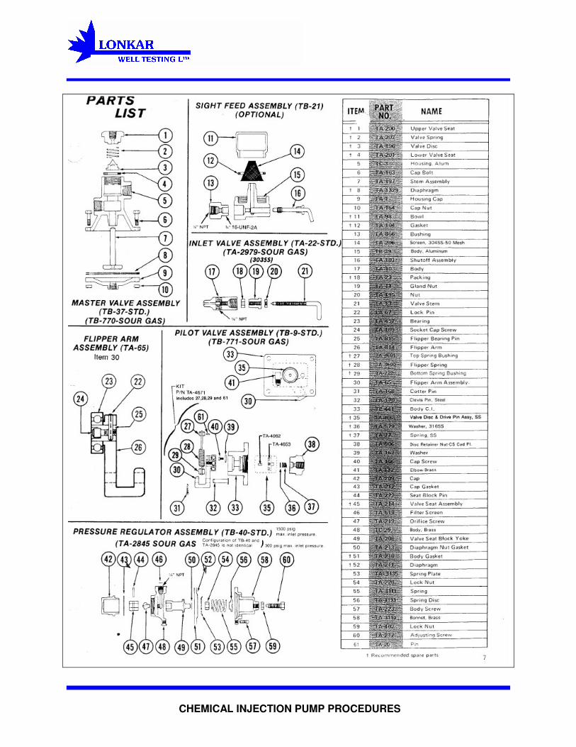
9 The pump is assembled with Item 47 plunger travel adjusting pin inserted in the hole of the plunger nearest the plunger packing gland nut. This is the position of longest stroke. To shorten the stroke, place the pin in the other hole.
10
Start the pump by slowly opening the TA-22 inlet valve. Prime the pump head by opening the TA-123 priming valve. After the pump discharges fluid without bubbles, close the priming valve for normal operation.
10
Pages of attached diagram will follow the procedures.
CHEMICAL INJECTION PUMP PROCEDURES

CHEMICAL INJECTION PUMP PROCEDURES

CHEMICAL INJECTION PUMP PROCEDURES