
05_30_08_16_30_17
58
R(E) Pair Application technical data Split Sky Air air conditioning systems
-
Upload
sopsky-salat -
Category
Documents
-
view
704 -
download
50
description
test
Transcript of 05_30_08_16_30_17
R(E)
Pair Application
technical data
SplitSky Air
air conditioning systems

Split - Sky Air
EED
E02-
1/1
• 05
/200
2Pr
epar
ed in
Bel
gium
by
Goe
kint
Gra
phic
s
Zandvoordestraat 300
B - 8400 Ostend Belgium
Internet: http://www.daikineurope.com
Specifications are subject to change without prior notice
ISO14001 assures an effective environmental management system in order to help protecthuman health and the environment from the potentialimpact of our activities, products and services and toassist in maintaining and improving the quality ofthe environment
Daikin Europe N.V. is approved by LRQA for its Quality Management System in accordance with the ISO9001 standard. ISO9001 pertains to quality assurance regarding design, development, manufacturing as well as to services related to the product.
Daikin units comply with the European regulations that guarantee the safety of the product.
Daikin Europe N.V. is participating in the EUROVENT Certification Programme.Products are as listed in the EUROVENT Directory of Certified Products.

TABLE OF CONTENTSR(E)
1 Features . . . . . . . . . . . . . . . . . . . . . . . . . . . . . . . . . . . . . . . . . . . . . . . . . . . . . . . . . . . . . . . . . . . . . . . . . . . . . . . . . 2
2 Specifications . . . . . . . . . . . . . . . . . . . . . . . . . . . . . . . . . . . . . . . . . . . . . . . . . . . . . . . . . . . . . . . . . . . . . . . 3
Technical specifications
Electrical specifications
3 Capacity tables . . . . . . . . . . . . . . . . . . . . . . . . . . . . . . . . . . . . . . . . . . . . . . . . . . . . . . . . . . . . . . . . . . . 13
4 Dimensional drawings . . . . . . . . . . . . . . . . . . . . . . . . . . . . . . . . . . . . . . . . . . . . . . . . . . . . . 28
5 Operation range . . . . . . . . . . . . . . . . . . . . . . . . . . . . . . . . . . . . . . . . . . . . . . . . . . . . . . . . . . . . . . . . . 31
6 Piping diagrams . . . . . . . . . . . . . . . . . . . . . . . . . . . . . . . . . . . . . . . . . . . . . . . . . . . . . . . . . . . . . . . . . . 34
7 Wiring diagrams . . . . . . . . . . . . . . . . . . . . . . . . . . . . . . . . . . . . . . . . . . . . . . . . . . . . . . . . . . . . . . . . . 38
8 Sound level . . . . . . . . . . . . . . . . . . . . . . . . . . . . . . . . . . . . . . . . . . . . . . . . . . . . . . . . . . . . . . . . . . . . . . . . . . 45
Sound level data
Sound pressure spectrum
9 Accessories . . . . . . . . . . . . . . . . . . . . . . . . . . . . . . . . . . . . . . . . . . . . . . . . . . . . . . . . . . . . . . . . . . . . . . . . . . 49
Optional accessories
10 Centre of gravity . . . . . . . . . . . . . . . . . . . . . . . . . . . . . . . . . . . . . . . . . . . . . . . . . . . . . . . . . . . . . . . . 50
11 Installation . . . . . . . . . . . . . . . . . . . . . . . . . . . . . . . . . . . . . . . . . . . . . . . . . . . . . . . . . . . . . . . . . . . . . . . . . . . . 51
12 Safety device settings . . . . . . . . . . . . . . . . . . . . . . . . . . . . . . . . . . . . . . . . . . . . . . . . . . . . . . 56
• Pair Application • R-22 • RE18-40GA/R25-45DC/R60FA/R71-250F
1• Split - Sky Air • Outdoor Units
1 Features
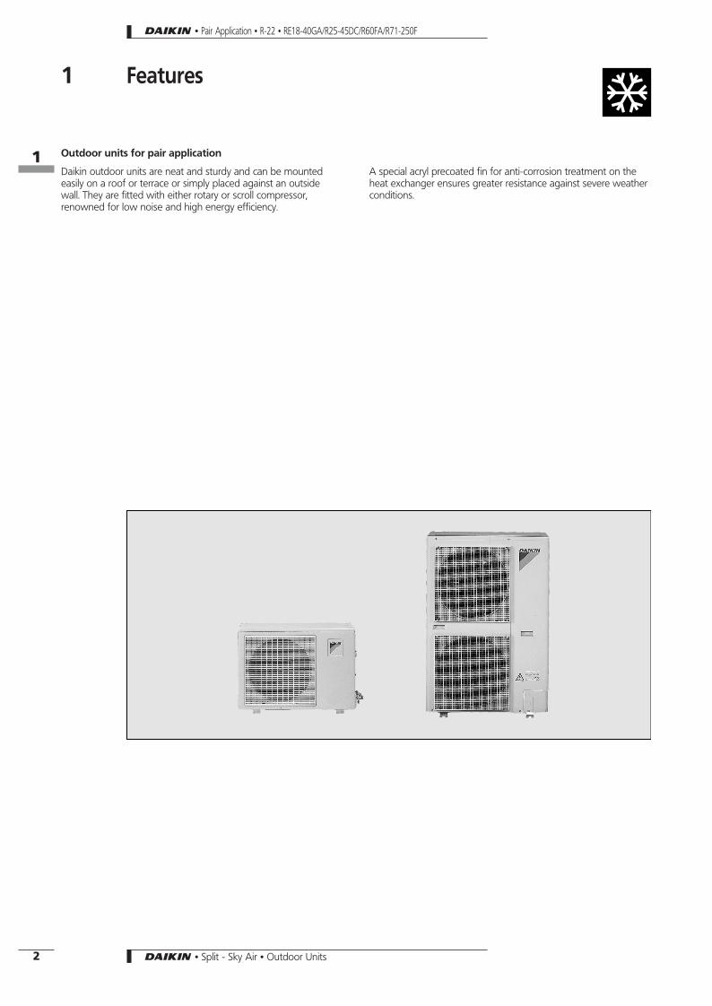
Outdoor units for pair application
Daikin outdoor units are neat and sturdy and can be mountedeasily on a roof or terrace or simply placed against an outsidewall. They are fitted with either rotary or scroll compressor,renowned for low noise and high energy efficiency.
A special acryl precoated fin for anti-corrosion treatment on theheat exchanger ensures greater resistance against severe weatherconditions.
• Pair Application • R-22 • RE18-40GA/R25-45DC/R60FA/R71-250F
161
2 • Split - Sky Air • Outdoor Units

2 Specifications
TECHNICAL SPECIFICATIONSOUTDOOR UNITS RE18GA7V1 RE40GA7V1 R25DC7V11 R35DC7V11DIMENSIONS Unit H mm 540 540 540 540
W mm 750 750 750 750D mm 270 270 270 270
WEIGHT kg 28 43 31 39MATERIAL Unit Painted metalCOLOUR Unit Ivory whiteSOUND LEVEL Sound pressure (1) high dBA 45 50 43 48
low dBA - - - -Sound power (2) dBA 56 63 56 61
FAN Air flow rate high m3/min 24 30 25 27Speed steps 1 step 2 steps
high rpm 685 865 710 815low rpm - - 325 490
Type - - - -Qty x model 1 x F62P15U22 1 x F62P45J22 1 x F62P15S22 1 x UE6S-31SA4PQty x motor output W 1 x 15 1 x 45 1 x 15 1 x 30
HEAT EXCHANGER Type WL fin, Hi-XA U-cooling tubeRows x stages x fin pitch mm 1 x 20 x 2.0 2 x 20 x 2.0 1 x 20 x 2.0 2 x 20 x 2.0Face area m2 0.381 0.372 0.381 0.372
REFRIGERANT CIRCUIT Refrigerant type R-22 R-22 R-22 R-22Refrigerant charge kg 0.65 1.2 0.85 1.4Additional refrigerant g/m 20g/m for piping length > 8m 20g/m for piping length > 8m 15m > 20g/m > 25m 15m > 20g/m > 25mMaximum interunit piping length m 15 15 25 25Maximum interunit level difference m 15 15 15 15No. of circuits Max. 1 Max. 1 Max. 1 Max. 1
COMPRESSOR Type Hermetically sealed rotary compressorQty x model 1 x RC17V1N-R 1 x RC60V1TNRT 1 x RC30BV1R2T 1 x PS40ATRV1Number of cylinders - - - -Speed rpm 2,850 2,850 2,850 2,850Oil type SUNISO 4GSDIOil charge volume ! 0.4 0.85 0.4 0.4Crankcase heater W - - - -
PIPING CONNECTIONS liquid mm φ6.4 φ6.4 φ6.4 φ6.4gas mm φ9.5 φ12.7 φ9.5 φ12.7drain mm φ18 x 4 φ18 x 4 φ18 φ18 x 3
INSULATION MATERIAL Heat insulation tape Both liquid and gas pipes
3TW01011-1B3TW01101-1C3TW00021-1F3TW00031-1G
• Pair Application • R-22 • RE18-40GA/R25-45DC/R60FA/R71-250F
162
3• Split - Sky Air • Outdoor Units
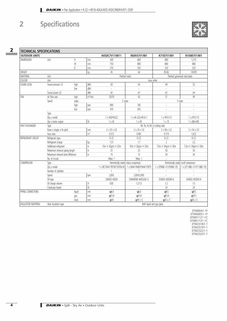
TECHNICAL SPECIFICATIONSOUTDOOR UNITS R45DC7V11/W11 R60FA7V1/W1 R71B7V1/W1 R100B7V1/W1DIMENSIONS Unit H mm 540 660 860 1,215
W mm 750 880 880 880D mm 270 350 320 320
WEIGHT kg 45 64 85/82 100/95MATERIAL Unit Painted metal Painted galvanised steel plateCOLOUR Unit Ivory whiteSOUND LEVEL Sound pressure (1) high dBA 50 54 49 52
low dBA - - - -Sound power (2) dBA 63 67 62 64
FAN Air flow rate high m3/min 30/29 43 51 94Speed steps 2 steps 3 steps
high rpm 890 785 - -low rpm 470 455 - -
Type - - - -Qty x model 1 x F62P45J22 1 x AF-220-49-6-1 1 x P47L11S 1 x P47L11SQty x motor output W 1 x 45 1 x 49 1 x 75 1 x (80+85)
HEAT EXCHANGER Type WL fin, Hi-XA U-cooling tubeRows x stages x fin pitch mm 2 x 20 x 2.0 2 x 24 x 2.0 2 x 38 x 2.0 2 x 54 x 2.0Face area m2 0.372 0.481 0.719 1,022
REFRIGERANT CIRCUIT Refrigerant type R-22 R-22 R-22 R-22Refrigerant charge kg 1.57 1.7 2 2.5Additional refrigerant m 15m > 20g/m > 25m 10m > 20g/m > 25m 7.5m > 30g/m > 50m 7.5m > 30g/m > 50mMaximum interunit piping length m 25 25 50 50Maximum interunit level difference m 15 15 30 30No. of circuits Max. 1 Max. 1 - -
COMPRESSOR Type Hermetically sealed rotary compressor Hermetically sealed scroll compressorQty x model 1 x (RC70AV1TRT/RC70YEN-R) 1 x (NH41VMDT/NH41YDPT) 1 x (JT90BC-V1/JT90BC-YE) 1 x (JT118BC-V1/JT118BC-YE)Number of cylinders 1 1 - -Speed rpm 2,850 2,850/2,900 - -Oil type SUNISO 4GSDI DIAMOND MS32(N-1) SUNISO 4GSDID-K SUNISO 4GSDID-KOil charge volume ! 0.85 1.2/1.3 1.2 1.5Crankcase heater W - - 33 33
PIPING CONNECTIONS liquid mm φ6.4 φ6.4 φ9.5 φ9.5gas mm φ15.9 φ15.9 φ15.9 φ19.1drain mm φ18 φ18 x 3 φ26 x 3 φ26 x 3
INSULATION MATERIAL Heat insulation tape Both liquid and gas pipes
3TW0041-1F3TW00051-1F3TW01121-1C3TW01131-1C
3TW23181-13TW23191-13TW23221-13TW23231-1
• Pair Application • R-22 • RE18-40GA/R25-45DC/R60FA/R71-250F
2 Specifications
162
4 • Split - Sky Air • Outdoor Units

TECHNICAL SPECIFICATIONSOUTDOOR UNITS R125B7W1 R200F7W1 R250F7W1DIMENSIONS Unit H mm 1,215 1,220 1,440
W mm 880 1,290 1,290D mm 320 700 700
WEIGHT kg 97 169 191MATERIAL Unit Painted galvanised steel plateCOLOUR Unit Ivory whiteSOUND LEVEL Sound pressure (1) high dBA 52 56 56
low dBA - - -Sound power (2) dBA 65 77 77
FAN Air flow rate high m3/min 91 150 170Speed steps 3 steps 1 step
high rpm - - -low rpm - - -
Type - - -Qty x model 2 x P47L11S 1 x P55J11F 1 x P55J11FQty x motor output W 1 x (80+85) & x (230+140) 230+140
HEAT EXCHANGER Type Non symm. waffle louvre, Hi-XA coolingtube
Assymetric louvre,J8 Hi-XA tube
Rows x stages x fin pitch mm 2 x 54 x 2.0 2 x 40 x 2 2 x 50 x 2Face area m2 1,022 1.57 1.97
REFRIGERANT CIRCUIT Refrigerant type R-22 R-22 R-22Refrigerant charge kg 3 5.55 6.025Additional refrigerant m 7.5m > 30g/m > 50m No additional refrigerant charge No additional refrigerant chargeMaximum interunit piping length m 50 70m equivalent 70m equivalentMaximum interunit level difference m 30 30 30No. of circuits - - -
COMPRESSOR Type Hermetically sealed scroll compressorQty x model 1 x JT150BC-YE 1 x JT236D-YE@2 1 x JT300D-YE@2Number of cylinders - - -Speed rpm - 2,900 2,900Oil type SUNISO 4GSDID-KOil charge volume ! 1.5 4 4Crankcase heater W 33 50 50
PIPING CONNECTIONS liquid mm φ9.5 φ12.7 x 0.90 φ15.9 x 0.95gas mm φ19.1 φ28.6 x 1.15 φ28.6 x 1.15drain mm φ26 x 3 φ26 x 6 φ26 x 6
INSULATION MATERIAL Heat insulation tape Both liquid and gas pipes
3TW23261-13TW21481-1C3TW21491-1C
• Pair Application • R-22 • RE18-40GA/R25-45DC/R60FA/R71-250F
2 Specifications
162
5• Split - Sky Air • Outdoor Units

ELECTRICAL SPECIFICATIONS
OUTDOOR UNITS RE18GA7V1 RE40GA7V1 R25DC7V11 R35DC7V11CURRENT Nominal running current A 2.5 7.1 3.8 6.1
Max. running current A - - - -Starting current A - - 18 26
OUTDOOR UNITS RE18GA7V1 RE40GA7V1 R25DC7V11 R35DC7V11POWER SUPPLY V1 V1 V1 V1NOMINAL DISTRIBUTIONSYSTEM VOLTAGE
Phase 1∼ 1∼ 1∼ 1∼Frequency Hz 50 50 50 50Voltage V 230 230 230 230
ELECTRICAL SPECIFICATIONS
OUTDOOR UNITS R45DC7V11/W11 R60FA7V1/W1 R71B7V1/W1 R100B7V1/W1CURRENT Nominal running current A 10.8/4.4 10.4/5.2 - -
Max. running current A - 13.5/6.7 - -Starting current A 44/19 53/27 - -
OUTDOOR UNITS R45DC7V11/W11 R60FA7V1/W1 R71B7V1/W1 R100B7V1/W1POWER SUPPLY V11/W11 V1/W1 V1/W1 V1/W1NOMINAL DISTRIBUTIONSYSTEM VOLTAGE
Phase 1∼/3N∼ 1∼/3N∼ 1∼/3N∼ 1∼/3N∼Frequency Hz 50 50 50 50Voltage V 230/400 230/400 230/400 230/400
ELECTRICAL SPECIFICATIONS
OUTDOOR UNITS R125B7W1 R200F7W1 R250F7W1CURRENT Nominal running current A - 18.9 19.2
Max. running current A - 21.9 22.8Starting current A - - -
OUTDOOR UNITS R125B7W1 R200F7W1 R250F7W1POWER SUPPLY W1 W1 W1NOMINAL DISTRIBUTIONSYSTEM VOLTAGE
Phase 3N∼ 3N∼ 3N∼Frequency Hz 50 50 50Voltage V 400 400 400
NOTES1 The sound pressure level is measured via a microphone at 1m distance from the unit. For measuring conditions: please refer to item 8 of this
chapter.
2 The sound power level is an absolute value indicating the ’’power’’ which a sound source generates.
• Pair Application • R-22 • RE18-40GA/R25-45DC/R60FA/R71-250F
2 Specifications
162
6 • Split - Sky Air • Outdoor Units

ELECTRICAL DATA
RE18GA7V1
Connection ratio (%) Indoor unitPower supply Compressor OFM IFM EH
Hz-Volts Voltage range MCA TOCA MFA LRA RLA W FLA W FLA W FLA
− FT18JV1B50-22050-23050-240
Max. 264VMin. 198V 3.1 - 15.0 11 2.2 15 0.2 19 0.2 − −
3TW01011-3B
RE40GA7V1
Connection ratio (%) Indoor unit Power supply Compressor OFM IFM EHHz-Volts Voltage range MCA TOCA MFA LRA RLA W FLA W FLA W FLA
− FT40GV1B50-22050-23050-240
Max. 264VMin. 198V 8.6 - 20.0 34 6.5 45 0.3 18 0.2 − −
− FL40GAV1NB50-22050-23050-240
Max. 264VMin. 198V 8.9 - 20.0 34 6.6 45 0.3 34 0.3 − −
3TW01101-3C
R25DC7V11
Connection ratio (%) Indoor unit Power supply Compressor OFM IFM EHHz-Volts Voltage range MCA TOCA MFA LRA RLA W FLA W FLA W FLA
− FT25JV1B50-22050-23050-240
Max. 264VMin. 198V 4.9 - 15.0 19 3.6 15 0.2 19 0.2 − −
− FL25GAV1NB50-22050-23050-240
Max. 264VMin. 198V 5.0 - 15.0 19 3.6 15 0.2 34 0.3 − −
− FHEB25GZ7V150-22050-23050-240
Max. 264VMin. 198V 5.1 - 15.0 19 3.8 15 0.2 10 0.2 − −
3TW00021-2D
R35DC7V11
Connection ratio (%) Indoor unit Power supply Compressor OFM IFM EHHz-Volts Voltage range MCA TOCA MFA LRA RLA W FLA W FLA W FLA
− FT35JV1B50-22050-23050-240
Max. 264VMin. 198V 7.2 - 15.0 26 5.4 30 0.3 19 0.2 − −
− FL35GAV1NB50-22050-23050-240
Max. 264VMin. 198V 7.3 - 15.0 26 5.4 30 0.3 34 0.3 − −
3TW00031-2C
SYMBOLSMCA : Min. Circuit AmpsTOCA : Total Over Current AmpsMFA : Max. Fuse AmpsLRA : Locked Rotor AmpsRLA : Rated Load Amps (A)OFM : Outdoor Fan MotorIFM : Indoor Fan MotorFLA : Full Load AmpsW : Rated motor output (W)EH : Electric heater
NOTES1. RLA is based on the following conditions:
Indoor temp.: 27°CDB/19.0°CWB2. TOCA means the total value of each OC set.3. Voltage range
Units are suitable for use on electrical systems where voltage suppliedto unit terminals is not below or above listed operation range limits
4. Maximum allowable voltage unbalance between phases is 2%.5. MCA/MFA
MCA = 1.25 x RLA + ea. FLA + 1.25 x EH FLAMFA < 2.25 x RLA + ea. FLA + 2.25 x EH FLA(next lower standard fuse rating, min.15A)
• Pair Application • R-22 • RE18-40GA/R25-45DC/R60FA/R71-250F
2 Specifications
162
7• Split - Sky Air • Outdoor Units

ELECTRICAL DATA
R45DC7V11
Connection ratio (%) Indoor unit Power supply Compressor OFM IFM EHHz-Volts Voltage range MCA TOCA MFA LRA RLA W FLA W FLA W FLA
− FT45GAV1B50-22050-23050-240
Max. 264VMin. 198V 12.9 - 25.0 44 9.9 45 0.3 40 0.2 − −
− FL45GAV1NB50-22050-23050-240
Max. 264VMin. 198V 12.7 - 25.0 44 9.7 45 0.3 34 0.3 − −
3TW00041-2C
R45DC7W11
Connection ratio (%) Indoor unit Power supply Compressor OFM IFM EHHz-Volts Voltage range MCA TOCA MFA LRA RLA W FLA W FLA W FLA
− FT45GAV1B50-38050-40050-415
Max. 400VMin. 342V 5.5 - 15.0 19 3.7 45 0.3 40 0.2 − −
− FL45GAV1NB50-38050-40050-415
Max. 440VMin. 342V 5.3 - 15.0 19 3.7 45 0.3 34 0.3 − −
3TW00051-2E
R60FA7V1/W1
Unit combination Power supply Compressor OFM IFM EHIndoor unit Outdoor unit Hz-Volts Voltage range MCA TOCA MFA LRA RLA W FLA W FLA W FLA
FT60GAV1B R60FA7V150-22050-23050-240
Max. 254VMin. 198V 13 − 20
525558
9.99.69.3
55.3 0.3 130 0.6 − −
FT60GAV1B R60FA7W1 50-400 Max. 440VMin. 360V 6.2 - 15 22 4.2 49 0.5 40 0.2 − −
3TW01121-2B + 3TW01131-2B
SYMBOLSMCA : Min. Circuit AmpsTOCA : Total Over Current AmpsMFA : Max. Fuse AmpsLRA : Locked Rotor AmpsRLA : Rated Load Amps (A)OFM : Outdoor Fan MotorIFM : Indoor Fan MotorFLA : Full Load AmpsW : Rated motor output (W)EH : Electric heater
NOTES1. RLA is based on the following conditions:.
Indoor temp.: 27°CDB/19,5°CWBOutdoor temp. : 35°CDB
2. TOCA means the total value of each OC set.3. Maximum allowable voltage variation between phases is 2%.4. Select wire size based on the larger value of MCA or TOCA5. Instead of fuse, use circuit breaker6. Units are suitable for use on electrical systems where voltage supplied
to unit terminals is not below or above listed operation range limits
• Pair Application • R-22 • RE18-40GA/R25-45DC/R60FA/R71-250F
2 Specifications
162
8 • Split - Sky Air • Outdoor Units
ELECTRICAL DATA
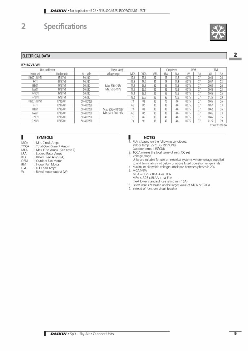
R71B7V1/W1
Unit combination Power supply Compressor OFM IFMIndoor unit Outdoor unit Hz - Volts Voltage range MCA TOCA MFA LRA RLA kW FLA kW FLA
FHYC71/FUY71 R71B7V1 50-230
Max. 50Hz-253VMin. 50Hz-197V
17.9 23.3 32 93 13.3 0.075 0.7 0.045 0.6FH71 R71B7V1 50-230 17.6 23.0 32 93 13.3 0.075 0.7 0.057 0.3FHY71 R71B7V1 50-230 17.9 23.3 32 93 13.3 0.075 0.7 0.062 0.6FAY71 R71B7V1 50-230 17.6 23.0 32 93 13.3 0.075 0.7 0.046 0.3FHYK71 R71B7V1 50-230 17.8 23.2 32 93 13.3 0.075 0.7 0.045 0.5FHYB71 R71B7V1 50-230 18.2 23.6 32 93 13.3 0.075 0.7 0.125 0.9
FHYC71/FUY71 R71B7W1 50-400/230
Max. 50Hz-400/253VMin. 50Hz-360/197V
7.1 8.8 16 40 4.6 0.075 0.7 0.045 0.6FH71 R71B7W1 50-400/230 6.8 8.5 16 40 4.6 0.075 0.7 0.057 0.3FHY71 R71B7W1 50-400/230 7.1 8.8 16 40 4.6 0.075 0.7 0.062 0.6FAY71 R71B7W1 50-400/230 6.8 8.5 16 40 4.6 0.075 0.7 0.046 0.3FHYK71 R71B7W1 50-400/230 7.0 8.7 16 40 4.6 0.075 0.7 0.045 0.5FHYB71 R71B7W1 50-400/230 7.4 9.1 16 40 4.6 0.075 0.7 0.125 0.9
3TW23189-2A
SYMBOLSMCA : Min. Circuit AmpsTOCA : Total Over Current AmpsMFA : Max. Fuse Amps (See note 7)LRA : Locked Rotor AmpsRLA : Rated Load Amps (A)OFM : Outdoor Fan MotorIFM : Indoor Fan MotorFLA : Full Load AmpsW : Rated motor output (W)
NOTES1. RLA is based on the following conditions:
Indoor temp.: 27°CDB/19,5°CWBOutdoor temp. : 35°CDB
2. TOCA means the total value of each OC set3. Voltage range
Units are suitable for use on electrical systems where voltage suppliedto unit terminals is not below or above listed operation range limits
4. Maximum allowable voltage unbalance between phases is 2%5. MCA/MFA
MCA = 1.25 x RLA + ea. FLAMFA ≤ 2.25 x RLAA + ea. FLA(next lower standard fuse rating min 16A)
6. Select wire size based on the larger value of MCA or TOCA7. Instead of fuse, use circuit breaker
• Pair Application • R-22 • RE18-40GA/R25-45DC/R60FA/R71-250F
2 Specifications
162
9• Split - Sky Air • Outdoor Units

ELECTRICAL DATA
R100B7V1/W1
Unit combination Power supply Compressor OFM IFMIndoor unit Outdoor unit Hz - Volts Voltage range MCA TOCA MFA LRA RLA kW FLA kW FLA
FHYC100FUY100 R100B7V1 50-230
Max. 50Hz-253VMin. 50Hz-197V
23.2 28.5 40 114 16.50.08+
0.085
0.84+0.7
0.09 1.0
FH100 R100B7V1 50-230 23.1 28.4 40 114 16.50.08+
0.085
0.84+0.7
0.13 0.9
FHY100 R100B7V1 50-230 22.9 28.2 40 114 16.50.08+
0.085
0.84+0.7
0.13 0.7
FHYB100 R100B7V1 50-230 23.2 28.5 40 114 16.50.08+
0.085
0.84+0.7
0.135 1.0
FAY100 R100B7V1 50-230 22.6 27.9 40 114 16.50.08+
0.085
0.84+0.7
0.049 0.4
FHYC100FUY100 R100B7W1 50-400/230
Max. 50Hz-400/253VMin. 50Hz-360/197V
9.8 12.5 16 53 5.80.08+
0.085
0.84+0.7
0.09 1.0
FH100 R100B7W1 50-400/230 9.7 12.4 16 53 5.80.08+
0.085
0.84+0.7
0.13 0.9
FHY100 R100B7W1 50-400/230 9.5 12.2 16 53 5.80.08+
0.085
0.84+0.7
0.13 0.7
FHYB100 R100B7W1 50-400/230 9.8 12.5 16 53 5.80.08+
0.085
0.84+0.7
0.135 1.0
FAY100 R100B7W1 50-400/230 9.2 11.9 16 53 5.80.08+
0.085
0.84+0.7
0.049 0.4
3TW23229-2A
SYMBOLSMCA : Min. Circuit AmpsTOCA : Total Over Current AmpsMFA : Max. Fuse Amps (see note 7)LRA : Locked Rotor AmpsRLA : Rated Load Amps (A)OFM : Outdoor Fan MotorIFM : Indoor Fan MotorFLA : Full Load AmpsW : Rated motor output (W)
NOTES1. RLA is based on the following conditions:
Indoor temp.: 27°CDB/19,5°CWBOutdoor temp. : 35°CDB
2. TOCA means the total value of each OC set3. Voltage range
Units are suitable for use on electrical systems where voltage suppliedto unit terminals is not below or above listed operation range limits
4. Maximum allowable voltage unbalance between phases is 2%5. MCA/MFA
MCA = 1.25 x RLA + ea. FLAMFA ≤ 2.25 x RLAA + ea. FLA(next lower standard fuse rating min 16A)
6. Select wire size based on the larger value of MCA or TOCA7. Instead of fuse, use circuit breaker
• Pair Application • R-22 • RE18-40GA/R25-45DC/R60FA/R71-250F
2 Specifications
162
10 • Split - Sky Air • Outdoor Units

ELECTRICAL DATA
R125B7W1
Unit combination Power supply Compressor OFM IFMIndoor unit Outdoor unit Hz - Volts Voltage range MCA TOCA MFA LRA RLA kW FLA kW FLA
FHYC125FUY125 R125B7W1 50-400/230
Max. 50Hz-440/253VMin. 50Hz-360/197V
11.5 15.5 20 67 7.20.085
+0.08
0.84+0.7
0.09 1.0
FH125 R125B7W1 50-400/230 11.4 15.4 20 67 7.20.085
+0.08
0.84+0.7
0.13 0.9
FHY125 R125B7W1 50-400/230 11.2 15.2 20 67 7.20.085
+0.08
0.84+0.7
0.13 0.7
FHYB125 R125B7W1 50-400/230 11.9 15.9 20 67 7.20.085
+0.08
0.84+0.7
0.225 1.4
FDY125 R125B7W1 50-400/230 14.7 18.7 20 67 7.20.085
+0.08
0.84+0.7
0.5 4.2
3TW23269-2
SYMBOLSMCA : Min. Circuit AmpsTOCA : Total Over Current AmpsMFA : Max. Fuse Amps (See note 7)LRA : Locked Rotor AmpsRLA : Rated Load Amps (A)OFM : Outdoor Fan MotorIFM : Indoor Fan MotorFLA : Full Load AmpsW : Rated motor output (W)
NOTES1. RLA is based on the following conditions:
Indoor temp.: 27°CDB/19,5°CWBOutdoor temp. : 35°CDB
2. TOCA means the total value of each OC set3. Voltage range
Units are suitable for use on electrical systems where voltage suppliedto unit terminals is not below or above listed operation range limits
4. Maximum allowable voltage unbalance between phases is 2%5. MCA/MFA
MCA = 1.25 x RLA + ea. FLAMFA ≤ 2.25 x RLAA + ea. FLA(next lower standard fuse rating, min.15A)
6. Select wire size based on the larger value of MCA or TOCA7. Instead of fuse, use circuit breaker
• Pair Application • R-22 • RE18-40GA/R25-45DC/R60FA/R71-250F
2 Specifications
162
11• Split - Sky Air • Outdoor Units

ELECTRICAL DATA
R200-250F7W1
Unit combination Power supply Compressor OFM IFMIndoor unit Outdoor unit Hz - Volts Voltage range MCA MFA LRA RLA kW FLA kW FLA
FDY200F7V1 R200F7W1 50-400Min. 360VMax. 440V
16.525+26
89 11.20.14+
0.23
1.1+
1.43650 6.8
FDY250F7V1 R250F7W1 50-400 19.332+16
89 13.40.14+
0.23
1.1+
1.431000 7.6
3TW21481-2A
SYMBOLSMCA : Min. Circuit AmpsTOCA : Total Over Current AmpsMFA : Max. Fuse Amps (See note 7)LRA : Locked Rotor AmpsRLA : Rated Load Amps (A)OFM : Outdoor Fan MotorIFM : Indoor Fan MotorFLA : Full Load AmpsW : Rated motor output (W)
NOTES1. RLA is based on the following conditions:
Indoor temp.: 27°CDB/19,5°CWBOutdoor temp. : 35°CDB
2. TOCA means the total value of each OC set3. Voltage range
Units are suitable for use on electrical systems where voltage suppliedto unit terminals is not below or above listed operation range limits
4. Maximum allowable voltage unbalance between phases is 2%5. MCA/MFA
MCA = 1.25 x RLA + ea. FLAMFA ≤ 2.25 x RLAA + ea. FLA(next lower standard fuse rating, min.15A)
6. Select wire size based on the larger value of MCA or TOCA7. Instead of fuse, use circuit breaker
• Pair Application • R-22 • RE18-40GA/R25-45DC/R60FA/R71-250F
2 Specifications
162
12 • Split - Sky Air • Outdoor Units
3 Capacity tables
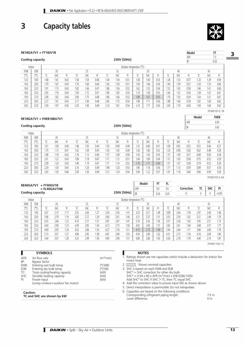
RE18GA7V1 + FT18JV1B
Cooling capacity 230V [50Hz]
Model FTAFR 7.3BF 0.28
Indoor Outdoor temperature (°C)EWB EDB 20 25 32 35 40 43(°C) (°C) TC SHC PI TC SHC PI TC SHC PI TC SHC PI TC SHC PI TC SHC PI12.0 18.0 1.68 1.61 0.42 1.58 1.54 0.46 1.44 1.44 0.51 1.38 1.40 0.53 1.28 1.33 0.57 1.23 1.29 0.5914.0 20.0 1.79 1.67 0.43 1.70 1.60 0.46 1.56 1.50 0.51 1.50 1.46 0.54 1.40 1.39 0.57 1.34 1.35 0.6016.0 22.0 1.91 1.73 0.43 1.82 1.66 0.47 1.68 1.56 0.52 1.62 1.52 0.54 1.52 1.45 0.58 1.46 1.41 0.6018.0 25.0 2.03 1.79 0.44 1.94 1.72 0.47 1.80 1.63 0.53 1.74 1.58 0.55 1.64 1.52 0.58 1.58 1.47 0.6119.0 27.0 2.09 1.82 0.44 2.00 1.75 0.48 1.86 1.66 0.53 1.80 1.61 0.55 1.70 1.55 0.59 1.64 1.51 0.6122.0 30.0 2.27 1.91 0.45 2.17 1.84 0.48 2.04 1.75 0.54 1.98 1.71 0.56 1.88 1.64 0.59 1.82 1.60 0.6224.0 32.0 2.39 1.97 0.45 2.29 1.90 0.49 2.16 1.81 0.54 2.10 1.77 0.56 2.00 1.70 0.60 1.94 1.66 0.62
3TW01012-1B
RE18GA7V1 + FHEB18BA7V1
Cooling capacity 230V [50Hz]
Model FHEBAFR 6.50BF 0.43
Indoor Outdoor temperature (°C)EWB EDB 20 25 32 35 40 46(°C) (°C) TC SHC PI TC SHC PI TC SHC PI TC SHC PI TC SHC PI TC SHC PI12.0 18.0 1.61 1.09 0.40 1.48 1.05 0.44 1.30 0.99 0.49 1.22 0.96 0.51 1.09 0.92 0.55 0.55 0.46 0.2714.0 20.0 1.75 1.13 0.41 1.62 1.09 0.45 1.43 1.03 0.49 1.36 1.00 0.52 1.23 0.96 0.56 0.62 0.48 0.2816.0 22.0 1.88 1.18 0.42 1.76 1.13 0.46 1.57 1.08 0.50 1.50 1.05 0.53 1.37 1.00 0.57 0.68 0.50 0.2818.0 25.0 2.01 1.22 0.43 1.89 1.18 0.47 1.71 1.12 0.51 1.64 1.09 0.54 1.51 1.05 0.58 0.75 0.52 0.2919.0 27.0 2.09 1.24 0.43 1.96 1.19 0.47 1.77 1.14 0.52 1.70 1.11 0.54 1.57 1.07 0.58 0.79 0.53 0.2922.0 30.0 2.29 1.30 0.45 2.16 1.26 0.49 1.98 1.20 0.53 1.90 1.18 0.56 1.77 1.13 0.59 0.89 0.57 0.3024.0 32.0 2.43 1.35 0.46 2.30 1.30 0.49 2.12 1.24 0.54 2.04 1.22 0.57 1.91 1.18 0.60 0.96 0.59 0.30
3TW01012-2A
RE40GA7V1 + FT40GV1B+ FL40GAV1NB
Cooling capacity 230V [50Hz]Correction TC SHC PI
FL 0 0 +0.05
Model FT FLAFR 8.3 6.5BF 0.24 0.20
Indoor Outdoor temperature (°C)EWB EDB 20 25 32 35 40 43(°C) (°C) TC SHC PI TC SHC PI TC SHC PI TC SHC PI TC SHC PI TC SHC PI12.0 18.0 3.67 2.73 1.17 3.55 2.66 1.27 3.34 2.56 1.41 3.25 2.51 1.48 3.08 2.44 1.59 2.97 2.40 1.6614.0 20.0 3.96 2.78 1.19 3.82 2.72 1.29 3.60 2.61 1.44 3.51 2.57 1.51 3.33 2.50 1.62 3.21 2.46 1.7016.0 22.0 4.25 2.84 1.22 4.10 2.77 1.31 3.87 2.67 1.47 3.76 2.63 1.54 3.57 2.56 1.65 3.45 2.51 1.7318.0 25.0 4.54 2.90 1.23 4.39 2.83 1.34 4.13 2.73 1.50 4.02 2.69 1.57 3.82 2.61 1.69 3.68 2.57 1.7719.0 27.0 4.69 2.93 1.24 4.52 2.86 1.35 4.27 2.76 1.51 4.15 2.72 1.58 3.94 2.64 1.71 3.80 2.60 1.7922.0 30.0 5.13 3.01 1.27 4.96 2.95 1.38 4.67 2.84 1.55 4.54 2.80 1.62 4.31 2.73 1.76 4.16 2.69 1.8424.0 32.0 5.44 3.07 1.28 5.25 2.99 1.40 4.94 2.90 1.57 4.80 2.86 1.65 4.56 2.78 1.79 4.40 2.74 1.87
3TW01102-1C
SYMBOLSAFR: Air flow rate (m3/min)BF: Bypass factorEWB: Entering wet bulb temp. (°CWB)EDB: Entering dry bulb temp. (°CDB)TC: Total cooling/heating capacity (kW)SHC: Sensible heating capacity (kW)PI: Power input (kW)
(comp.+indoor+outdoor fan motor)
Caution:TC and SHC are shown by kW
NOTES1. Ratings shown are net capacities which include a deduction for indoor fan
motor heat2. Shows nominal capacities3. SHC is based on each EWB and EDB
SHC* = SHC correction for other dry bulbSHC* = 0.34 x 60 x AFR (m3/min) x (DB-EDB)/1000.Add SHC* to SHC if SHC > TC, then TC equal SHC
4. Add the correction value to power input (W) as shown above5. Direct interpolation is permissible. Do not extrapolate.6. Capacities are based on the following conditions:
Corresponding refrigerant piping length: 7.5 mLevel difference: 0 m
• Pair Application • R-22 • RE18-40GA/R25-45DC/R60FA/R71-250F
163
13• Split - Sky Air • Outdoor Units

R25DC7V11 (R25DB7V11) + FT25JV1B+ FL25GAV1NB
Cooling capacity 230V [50Hz]
Model FT FLAFR 6.6 7.5BF 0.24 0.21
Indoor Outdoor temperature (°C)EWB EDB 20 25 32 35 40 46(°C) (°C) TC SHC PI TC SHC PI TC SHC PI TC SHC PI TC SHC PI TC SHC PI12.0 18.0 2.34 1.95 0.67 2.20 1.87 0.72 2.00 1.75 0.80 1.92 1.70 0.83 1.77 1.61 0.88 1.60 1.51 0.9414.0 20.0 2.50 2.01 0.68 2.35 1.93 0.73 2.15 1.81 0.81 2.07 1.75 0.84 1.93 1.67 0.89 1.75 1.57 0.9516.0 22.0 2.65 2.07 0.69 2.51 1.98 0.74 2.31 1.86 0.81 2.22 1.81 0.85 2.08 1.73 0.90 1.91 1.62 0.9618.0 25.0 2.80 2.13 0.70 2.66 2.04 0.75 2.46 1.92 0.82 2.37 1.87 0.86 2.23 1.78 0.91 2.06 1.68 0.9719.0 27.0 2.88 2.15 0.71 2.74 2.07 0.76 2.54 1.95 0.83 2.45 1.90 0.86 2.31 1.81 0.91 2.14 1.71 0.9722.0 30.0 3.11 2.24 0.72 2.96 2.16 0.77 2.76 2.04 0.84 2.68 1.99 0.87 2.54 1.90 0.93 2.37 1.80 0.9924.0 32.0 3.26 2.30 0.73 3.12 2.21 0.78 2.92 2.09 0.85 2.83 2.04 0.88 2.69 1.96 0.94 2.52 1.85 1.00
3TW00022-2D
R25DC7V11 + FHEB25GZ7V1
Cooling capacity 230V [50Hz]
Model FHEB25AFR 6.5BF 0.43
Indoor Outdoor temperature (°C)EWB EDB 20 25 32 35 40 46°C °C TC SHC PI TC SHC PI TC SHC PI TC SHC PI TC SHC PI TC SHC PI12.0 18.0 2.30 1.91 0.69 2.16 1.83 0.74 1.96 1.71 0.81 1.88 1.66 0.85 1.74 1.58 0.90 1.57 1.48 0.9614.0 20.0 2.44 1.97 0.70 2.31 1.89 0.75 2.11 1.77 0.82 2.03 1.72 0.86 1.89 1.64 0.91 1.72 1.54 0.9716.0 22.0 2.59 2.03 0.71 2.45 1.94 0.76 2.26 1.83 0.83 2.18 1.78 0.87 2.04 1.69 0.92 1.87 1.59 0.9818.0 25.0 2.74 2.08 0.72 2.60 2.00 0.77 2.41 1.88 0.84 2.33 1.83 0.88 2.19 1.75 0.93 2.02 1.65 0.9919.0 27.0 2.82 2.11 0.72 2.68 2.03 0.77 2.48 1.91 0.85 2.40 1.86 0.88 2.26 1.78 0.93 2.09 1.68 1.0022.0 30.0 3.04 2.20 0.74 2.90 2.11 0.79 2.71 1.99 0.86 2.62 1.94 0.89 2.48 1.86 0.95 2.32 1.76 1.0124.0 32.0 3.19 2.25 0.75 3.05 2.17 0.80 2.86 2.05 0.87 2.77 2.00 0.90 2.63 1.92 0.96 2.47 1.82 1.02
3TW00022-2D
R35DC7V11 + FT35GV1B+ FL35GV1NB
Cooling capacity 230V [50Hz]Correction TC SHC PI
FL +0.05 +0.05 +0.02
Model FT FLAFR 7.8 8BF 0.26 0.31
Indoor Outdoor temperature (°C)EWB EDB 20 25 32 35 40 46(°C) (°C) TC SHC PI TC SHC PI TC SHC PI TC SHC PI TC SHC PI TC SHC PI12.0 18.0 3.24 2.54 0.92 3.07 2.46 1.01 2.84 2.33 1.13 2.74 2.28 1.18 2.57 2.19 1.27 2.37 2.08 1.3814.0 20.0 3.42 2.59 0.94 3.25 2.50 1.03 3.01 2.37 1.15 2.91 2.32 1.21 2.74 2.23 1.30 2.54 2.12 1.4016.0 22.0 3.59 2.63 0.97 3.42 2.54 1.06 3.19 2.41 1.18 3.09 2.36 1.23 2.92 2.27 1.32 2.72 2.17 1.4318.0 25.0 3.77 2.67 0.99 3.60 2.58 1.08 3.36 2.45 1.20 3.26 2.40 1.26 3.09 2.31 1.35 2.89 2.21 1.4519.0 27.0 3.86 2.69 1.01 3.69 2.60 1.09 3.45 2.48 1.22 3.35 2.42 1.27 3.18 2.33 1.36 2.98 2.23 1.4622.0 30.0 4.12 2.75 1.04 3.95 2.66 1.13 3.71 2.54 1.25 3.61 2.48 1.31 3.44 2.40 1.40 3.24 2.29 1.5024.0 32.0 4.29 2.79 1.07 4.12 2.70 1.16 3.89 2.58 1.28 3.79 2.52 1.33 3.62 2.44 1.42 3.42 2.33 1.53
3TW00032-6C
SYMBOLSAFR: Air flow rate (m3/min)BF: Bypass factorEWB: Entering wet bulb temp. (°CWB)EDB: Entering dry bulb temp. (°CDB)TC: Total cooling/heating capacity (kW)SHC: Sensible heating capacity (kW)PI: Power input (kW)
(comp.+indoor+outdoor fan motor)
Caution:TC and SHC are shown by kW
NOTES1. Ratings shown are net capacities which include a deduction for indoor fan
motor heat2. Shows nominal capacities3. SHC is based on each EWB and EDB
SHC* = SHC correction for other dry bulbSHC* = 0.34 x 60 x AFR (m3/min) x (DB-EDB)/1000.Add SHC* to SHC if SHC > TC, then TC equal SHC
4. Add the correction value to power input (W) as shown above5. Direct interpolation is permissible. Do not extrapolate.6. Capacities are based on the following conditions:
Corresponding refrigerant piping length: 7.5 mLevel difference: 0 m
• Pair Application • R-22 • RE18-40GA/R25-45DC/R60FA/R71-250F
3 Capacity tables
163
14 • Split - Sky Air • Outdoor Units

R45DC7V11 + FT45GAV1B+ FL40GAV1NB
Cooling capacity 230V [50Hz]400V [50Hz]
Correction TC SHC PIFL -0.1 -0.06 -0.03
Model FT FLAFR 11.8 10.7BF 0.18 0.18
Indoor Outdoor temperature (°C)EWB EDB 20 25 32 35 40 46°C °C TC SHC PI TC SHC PI TC SHC PI TC SHC PI TC SHC PI TC SHC PI12.0 18.0 4.86 3.43 1.53 4.62 3.34 1.69 4.28 3.22 1.92 4.14 3.17 2.02 3.89 3.08 2.18 3.60 2.97 2.3814.0 20.0 5.18 3.50 1.57 4.94 3.41 1.73 4.60 3.29 1.96 4.45 3.24 2.06 4.21 3.15 2.22 3.92 3.04 2.4216.0 22.0 5.50 3.57 1.61 5.26 3.48 1.77 4.92 3.36 2.00 4.77 3.31 2.10 4.53 3.22 2.26 4.24 3.11 2.4618.0 25.0 5.82 3.64 1.65 5.58 3.55 1.81 5.24 3.43 2.04 5.09 3.38 2.14 4.85 3.29 2.30 4.56 3.18 2.5019.0 27.0 5.98 3.68 1.67 5.73 3.59 1.83 5.40 3.47 2.06 5.25 3.41 2.16 5.01 3.32 2.32 4.72 3.22 2.5222.0 30.0 6.45 3.78 1.73 6.21 3.69 1.89 5.87 3.57 2.12 5.73 3.52 2.22 5.49 3.43 2.38 5.19 3.32 2.5824.0 32.0 6.77 3.85 1.77 6.53 3.76 1.93 6.19 3.64 2.16 6.05 3.59 2.26 5.80 3.50 2.42 5.51 3.39 2.62
3TW00042-6C
R45DC7W11 + FT45GAV1B+ FL45GAV1NB
Cooling capacity 230V [50Hz]400V [50Hz]
Correction TC SHC PIFL -0.1 -0.06 -0.03
Model FT FLAFR 11.8 10.7BF 0.18 0.18
Indoor Outdoor temperature (°C)EWB EDB 20 25 32 35 40 46°C °C TC SHC PI TC SHC PI TC SHC PI TC SHC PI TC SHC PI TC SHC PI12.0 18.0 4.86 3.43 1.42 4.62 3.34 1.58 4.28 3.22 1.81 4.14 3.17 1.91 3.89 3.08 2.07 3.60 2.97 2.2714.0 20.0 5.18 3.50 1.46 4.94 3.41 1.62 4.60 3.29 1.85 4.45 3.24 1.95 4.21 3.15 2.11 3.92 3.04 2.3116.0 22.0 5.50 3.57 1.50 5.26 3.48 1.66 4.92 3.36 1.89 4.77 3.31 1.99 4.53 3.22 2.15 4.24 3.11 2.3518.0 25.0 5.82 3.64 1.54 5.58 3.55 1.70 5.24 3.43 1.93 5.09 3.38 2.03 4.85 3.29 2.19 4.56 3.18 2.3919.0 27.0 5.98 3.68 1.56 5.73 3.59 1.72 5.40 3.47 1.95 5.25 3.41 2.05 5.01 3.32 2.21 4.72 3.22 2.4122.0 30.0 6.45 3.78 1.62 6.21 3.69 1.78 5.87 3.57 2.01 5.73 3.52 2.11 5.49 3.43 2.27 5.19 3.32 2.4724.0 32.0 6.77 3.85 1.66 6.53 3.76 1.82 6.19 3.64 2.05 6.05 3.59 2.15 5.80 3.50 2.31 5.51 3.39 2.51
3TW00052-1C
R60FA7V1,W1 + FT60GAV1B
Cooling capacity 230V [50Hz]400V [50Hz]
Model FT FVAFR 13.3 13.7BF 0.15 0.18
Indoor Outdoor temperature (°C)EWB EDB 20 25 32 35 40 46(°C) (°C) TC SHC PI TC SHC PI TC SHC PI TC SHC PI TC SHC PI TC SHC PI12.0 18.0 5.95 4.46 1.58 5.69 4.39 1.78 5.32 4.28 2.06 5.16 4.24 2.18 4.90 4.16 2.37 4.58 4.07 2.6114.0 20.0 6.29 4.52 1.63 6.03 4.45 1.83 5.66 4.34 2.11 5.50 4.30 2.23 5.24 4.22 2.42 4.92 4.13 2.6616.0 22.0 6.63 4.58 1.68 6.37 4.51 1.88 6.00 4.40 2.16 5.84 4.36 2.28 5.58 4.28 2.47 5.26 4.19 2.7118.0 25.0 6.97 4.64 1.73 6.71 4.57 1.93 6.34 4.46 2.21 6.18 4.42 2.33 5.92 4.34 2.52 5.60 4.25 2.7619.0 27.0 7.14 4.67 1.76 6.88 4.60 1.96 6.51 4.49 2.23 6.35 4.45 2.35 6.09 4.37 2.55 5.77 4.28 2.7822.0 30.0 7.65 4.76 1.83 7.39 4.69 2.03 7.02 4.58 2.31 6.86 4.54 2.43 6.60 4.46 2.62 6.28 4.37 2.8624.0 32.0 7.99 4.82 1.88 7.73 4.75 2.08 7.36 4.64 2.36 7.20 4.60 2.48 6.94 4.52 2.67 6.62 4.43 2.91
3TW01122-1B
SYMBOLSAFR: Air flow rate (m3/min)BF: Bypass factorEWB: Entering wet bulb temp. (°CWB)EDB: Entering dry bulb temp. (°CDB)TC: Total cooling/heating capacity (kW)SHC: Sensible heating capacity (kW)PI: Power input (kW)
(comp.+indoor+outdoor fan motor)
Caution:TC and SHC are shown by kW
NOTES1. Ratings shown are net capacities which include a deduction for indoor fan
motor heat2. Shows nominal capacities3. SHC is based on each EWB and EDB
SHC* = SHC correction for other dry bulbSHC* = 0.34 x 60 x AFR (m3/min) x (DB-EDB)/1000.Add SHC* to SHC if SHC > TC, then TC equal SHC
4. Add the correction value to power input (W) as shown above5. Direct interpolation is permissible. Do not extrapolate.6. Capacities are based on the following conditions:
Corresponding refrigerant piping length: 7.5 mLevel difference: 0 m
• Pair Application • R-22 • RE18-40GA/R25-45DC/R60FA/R71-250F
3 Capacity tables
163
15• Split - Sky Air • Outdoor Units

FH35∼60 + R35DC7V11R45DC7V11/W11R60FA7V1/W1
Cooling capacity V11: 230V [50Hz]W11: 400V [50Hz]
FH..BModel 35 45 60AFR 13 13 16BF 0.2 0.09 0.10
OutdoorIndoor Outdoor temperature (°CDB)
EWB(°C)
EDB(°C)
20 25 32 35 40 46TC SHC PI TC SHC PI TC SHC PI TC SHC PI TC SHC PI TC SHC PI
35
12.0 18.0 3.98 2.84 1.06 3.76 2.73 1.18 3.48 2.60 1.32 3.34 2.53 1.40 3.15 2.44 1.50 2.90 2.33 1.6414.0 20.0 4.20 2.87 1.09 3.98 2.77 1.21 3.70 2.65 1.36 3.56 2.59 1.43 3.35 2.49 1.53 3.11 2.37 1.6716.0 22.0 4.40 2.92 1.14 4.21 2.82 1.24 3.90 2.69 1.39 3.79 2.64 1.46 3.57 2.53 1.57 3.32 2.42 1.7018.0 25.0 4.62 2.97 1.16 4.42 2.87 1.27 4.12 2.73 1.42 4.00 2.67 1.49 3.79 2.58 1.59 3.54 2.45 1.7319.0 27.0 4.73 2.99 1.18 4.53 2.90 1.28 4.23 2.75 1.43 4.05 2.69 1.50 3.89 2.60 1.61 3.65 2.48 1.7419.5 27.0 4.79 3.00 1.18 4.57 2.91 1.29 4.29 2.76 1.44 4.22 2.70 1.51 3.96 2.61 1.61 3.71 2.48 1.7522.0 30.0 5.05 3.05 1.21 4.75 2.95 1.32 4.56 2.82 1.48 4.43 2.76 1.54 4.23 2.67 1.65 3.98 2.54 1.7924.0 32.0 5.28 3.09 1.25 5.07 3.00 1.36 4.78 2.86 1.51 4.64 2.81 1.58 4.44 2.70 1.69 4.20 2.60 1.81
45
12.0 18.0 4.73 3.52 1.60 4.58 3.43 1.73 4.31 3.29 1.92 4.19 3.24 2.01 3.97 3.15 2.16 3.68 3.05 2.3614.0 20.0 5.11 3.59 1.63 4.93 3.51 1.76 4.65 3.36 1.96 4.52 3.31 2.05 4.29 3.22 2.21 3.98 3.12 2.4116.0 22.0 5.47 3.66 1.66 5.29 3.58 1.79 4.99 3.44 2.00 4.85 3.38 2.09 4.61 3.29 2.25 4.28 3.19 2.4618.0 25.0 5.85 3.73 1.68 5.66 3.65 1.82 5.33 3.52 2.04 5.19 3.46 2.13 4.92 3.36 2.30 4.58 3.26 2.5119.0 27.0 6.04 3.78 1.69 5.83 3.68 1.84 5.50 3.56 2.05 5.35 3.50 2.15 5.07 3.41 2.32 4.72 3.29 2.5419.5 27.0 6.12 3.80 1.70 5.93 3.69 1.84 5.59 3.58 2.06 5.44 3.52 2.16 5.16 3.43 2.33 4.79 3.31 2.5522.0 30.0 6.62 3.88 1.73 6.39 3.80 1.88 6.02 3.66 2.11 5.85 3.61 2.21 5.56 3.52 2.39 5.18 3.41 2.6124.0 32.0 7.02 3.95 1.75 6.77 3.86 1.91 6.37 3.73 2.14 6.19 3.68 2.25 5.87 3.59 2.43 5.46 3.49 2.66
60
12.0 18.0 5.98 4.05 1.72 5.78 3.97 1.88 5.49 3.87 2.13 5.36 3.82 2.24 5.13 3.76 2.44 4.84 3.66 2.7314.0 20.0 6.32 4.11 1.75 6.12 4.03 1.91 5.81 3.93 2.17 5.67 3.88 2.29 5.43 3.81 2.51 5.12 3.73 2.7916.0 22.0 6.67 4.18 1.79 6.46 4.09 1.96 6.14 3.99 2.22 5.99 3.94 2.34 5.74 3.87 2.56 5.41 3.79 2.8518.0 25.0 7.04 4.24 1.82 6.82 4.16 2.00 6.48 4.05 2.27 6.33 4.00 2.40 6.06 3.93 2.62 5.71 3.84 2.9119.0 27.0 7.23 4.26 1.84 7.01 4.19 2.02 6.66 4.08 2.29 6.50 4.03 2.42 6.22 3.96 2.65 5.86 3.87 2.9422.0 30.0 7.82 4.35 1.90 7.58 4.27 2.09 7.21 4.18 2.37 7.03 4.13 2.51 6.73 4.05 2.74 6.34 3.96 3.0324.0 32.0 8.22 4.41 1.95 7.97 4.33 2.14 7.59 4.24 2.43 7.40 4.19 2.56 7.08 4.11 2.80 5.69 4.02 3.09
3TW01582-4+3TW01122-2C
SYMBOLS
AFR: Air flow rate (m3/min)BF: Bypass factorEWB: Entering wet bulb temp. (°CWB)EDB: Entering dry bulb temp. (°CDB)ED*: Dry bulb temperature (°CDB)TC: Total cooling capacity (kW)SHC: Sensible heating capacity (kW)PI: Power input (kW)
(comp.+indoor+outdoor fan motor)
Caution:TC and SHC are shown by kWV1(1): 230VW1(1): 400V
NOTES
1. Ratings shown are net capacities which include a deduction for indoorfan motor heat
2. Shows nominal capacities3. SHC is based on each EWB and EDB
SHC* = SHC correction for other dry bulbSHC* = 0.34 x 60 x AFR (m3/min) x (DB-EDB)/1000.Add SHC* to SHC if SHC > TC, then TC equal SHC
4. Direct interpolation is permissible.Do not extrapolate.
5. Capacities are based on the following conditions:Corresponding refrigerant piping length: 7.5 mLevel difference: 0 m
• Pair Application • R-22 • RE18-40GA/R25-45DC/R60FA/R71-250F
3 Capacity tables
163
16 • Split - Sky Air • Outdoor Units

FHC35∼60 + R35DC7V11R45DC7V11/W11R60FA7V1/W1
Cooling capacity V11: 230V [50Hz]W11: 400V [50Hz]
FHC..BModel 35 45 60AFR 14 15 18.0BF 0.16 0.12 0.10
OutdoorIndoor Outdoor temperature (°CDB)
EWB(°C)
EDB(°C)
20 25 32 35 40 46TC SHC PI TC SHC PI TC SHC PI TC SHC PI TC SHC PI TC SHC PI
35
12.0 18.0 3.83 2.73 0.96 3.62 2.63 1.07 3.35 2.50 1.20 3.22 2.44 1.27 3.03 2.35 1.36 2.79 2.24 1.4914.0 20.0 4.04 2.76 0.99 3.83 2.67 1.10 3.56 2.55 1.23 3.43 2.49 1.30 3.23 2.40 1.39 2.99 2.28 1.5116.0 22.0 4.24 2.81 1.03 4.05 2.72 1.12 3.76 2.59 1.26 3.65 2.54 1.32 3.44 2.44 1.42 3.20 2.33 1.5418.0 25.0 4.45 2.86 1.05 4.26 2.76 1.15 3.97 2.63 1.29 3.85 2.57 1.35 3.65 2.48 1.44 3.41 2.36 1.5719.0 27.0 4.55 2.88 1.07 4.36 2.79 1.16 4.07 2.65 1.30 3.90 2.59 1.36 3.75 2.50 1.46 3.51 2.39 1.5819.5 27.0 4.61 2.89 1.07 4.40 2.80 1.17 4.13 2.66 1.31 4.06 2.60 1.37 3.81 2.51 1.46 3.57 2.39 1.5922.0 30.0 4.86 2.94 1.10 4.57 2.84 1.20 4.39 2.72 1.34 4.27 2.66 1.40 4.07 2.57 1.50 3.83 2.45 1.6224.0 32.0 5.08 2.98 1.13 4.88 2.89 1.23 4.60 2.75 1.37 4.47 2.71 1.43 4.28 2.60 1.53 4.04 2.50 1.64
45
12.0 18.0 4.60 3.42 1.60 4.45 3.33 1.73 4.19 3.20 1.92 4.07 3.15 2.01 3.86 3.06 2.16 3.58 2.96 2.3614.0 20.0 4.97 3.49 1.63 4.79 3.41 1.76 4.52 3.27 1.96 4.39 3.22 2.05 4.17 3.13 2.21 3.87 3.03 2.4116.0 22.0 5.32 3.56 1.66 5.14 3.48 1.79 4.85 3.34 2.00 4.71 3.29 2.09 4.48 3.20 2.25 4.16 3.10 2.4618.0 25.0 5.69 3.63 1.68 5.50 3.55 1.82 5.18 3.42 2.04 5.04 3.36 2.13 4.78 3.27 2.30 4.45 3.17 2.5119.0 27.0 5.87 3.67 1.69 5.67 3.58 1.84 5.35 3.46 2.05 5.20 3.41 2.15 4.93 3.31 2.32 4.59 3.20 2.5419.5 27.0 5.95 3.69 1.70 5.76 3.59 1.84 5.43 3.48 2.06 5.29 3.42 2.16 5.02 3.33 2.33 4.66 3.22 2.5522.0 30.0 6.43 3.77 1.73 6.21 3.69 1.88 5.85 3.56 2.11 5.69 3.51 2.21 5.40 3.42 2.39 5.03 3.31 2.6124.0 32.0 6.82 3.84 1.75 6.58 3.75 1.91 6.19 3.63 2.14 6.02 3.58 2.25 5.71 3.49 2.43 5.31 3.39 2.66
60
12.0 18.0 5.98 4.05 1.72 5.78 3.97 1.88 5.49 3.87 2.13 5.36 3.82 2.24 5.13 3.76 2.44 4.84 3.66 2.7314.0 20.0 6.32 4.11 1.75 6.12 4.03 1.91 5.81 3.93 2.17 5.67 3.88 2.29 5.43 3.81 2.51 5.12 3.73 2.7916.0 22.0 6.67 4.18 1.79 6.46 4.09 1.96 6.14 3.99 2.22 5.99 3.94 2.34 5.74 3.87 2.56 5.41 3.79 2.8518.0 25.0 7.04 4.24 1.82 6.82 4.16 2.00 6.48 4.05 2.27 6.33 4.00 2.40 6.06 3.93 2.62 5.71 3.84 2.9119.0 27.0 7.23 4.26 1.84 7.01 4.19 2.02 6.66 4.08 2.29 6.50 4.03 2.42 6.22 3.96 2.65 5.86 3.87 2.9422.0 30.0 7.82 4.35 1.90 7.58 4.27 2.09 7.21 4.18 2.37 7.03 4.13 2.51 6.73 4.05 2.74 6.34 3.96 3.0324.0 32.0 8.22 4.41 1.95 7.97 4.33 2.14 7.59 4.24 2.43 7.40 4.19 2.56 7.08 4.11 2.80 5.69 4.02 3.09
3TW01582-3+3TW01122-2C
SYMBOLS
AFR: Air flow rate (m3/min)BF: Bypass factorEWB: Entering wet bulb temp. (°CWB)EDB: Entering dry bulb temp. (°CDB)ED*: Dry bulb temperature (°CDB)TC: Total cooling capacity (kW)SHC: Sensible heating capacity (kW)PI: Power input (kW)
(comp.+indoor+outdoor fan motor)
Caution:TC and SHC are shown by kWV1(1): 230VW1(1): 400V
NOTES
1. Ratings shown are net capacities which include a deduction for indoorfan motor heat
2. Shows nominal capacities3. SHC is based on each EWB and EDB
SHC* = SHC correction for other dry bulbSHC* = 0.34 x 60 x AFR (m3/min) x (DB-EDB)/1000.Add SHC* to SHC if SHC > TC, then TC equal SHC
4. Direct interpolation is permissible.Do not extrapolate.
5. Capacities are based on the following conditions:Corresponding refrigerant piping length: 7.5 mLevel difference: 0 m
• Pair Application • R-22 • RE18-40GA/R25-45DC/R60FA/R71-250F
3 Capacity tables
163
17• Split - Sky Air • Outdoor Units

SYMBOLS
AFR: Air flow rate (m3/min)BF: Bypass factorEWB: Entering wet bulb temp. (°CWB)EDB: Entering dry bulb temp. (°CDB)TC: Total cooling capacity (kW)SHC: Sensible heating capacity (kW)PI: Power input (kW)
(comp.+indoor+outdoor fan motor)
Caution:TC and SHC are shown by kWV1(1): 230VW1(1): 400V
NOTES
1. Ratings shown are net capacities which include a deduction for indoorfan motor heat
2. Shows nominal capacities3. SHC is based on each EWB and EDB
SHC* = SHC correction for other dry bulbSHC* = 0.34 x 60 x AFR (m3/min) x (DB-EDB)/1000.Add SHC* to SHC if SHC > TC, then TC equal SHC
4. Direct interpolation is permissible.Do not extrapolate.
5. Capacities are based on the following conditions:Corresponding refrigerant piping length: 7.5 mLevel difference: 0 m
6. Air flow rate and BF are tabulated below.
Model FHB
35AFR 11.5BF 0.15
45AFR 14BF 0.16
60AFR 17BF 0.10
FHB35-60 + R35DC7V11R45DC7V11/W11R60FA7V1/W1
Cooling capacity 230V [50Hz]
OutdoorIndoor Outdoor temperature (°CDB)
EWB(°C)
EDB(°C)
20 25 32 35 40 46TC SHC PI TC SHC PI TC SHC PI TC SHC PI TC SHC PI TC SHC PI
35
12.0 18.0 3.88 2.77 0.96 3.67 2.66 1.07 3.39 2.53 1.20 3.26 2.47 1.27 3.07 2.38 1.36 2.82 2.27 1.4914.0 20.0 4.09 2.80 0.99 3.88 2.71 1.10 3.60 2.58 1.23 3.47 2.52 1.30 3.28 2.43 1.39 3.03 2.31 1.5116.0 22.0 4.30 2.85 1.03 4.10 2.75 1.12 3.81 2.63 1.26 3.69 2.57 1.32 3.49 2.47 1.42 3.24 2.36 1.5418.0 25.0 4.51 2.89 1.05 4.31 2.80 1.15 4.02 2.66 1.29 3.90 2.60 1.35 3.69 2.51 1.44 3.45 2.39 1.5719.0 27.0 4.61 2.92 1.07 4.41 2.82 1.16 4.12 2.68 1.30 3.95 2.63 1.36 3.80 2.53 1.46 3.56 2.42 1.5819.5 27.0 4.67 2.93 1.07 4.46 2.83 1.17 4.18 2.70 1.31 4.11 2.64 1.37 3.86 2.54 1.46 3.61 2.42 1.5922.0 30.0 4.93 2.97 1.10 4.73 2.88 1.20 4.46 2.75 1.34 4.32 2.70 1.40 4.12 2.60 1.50 3.88 2.49 1.6224.0 32.0 5.15 3.02 1.13 4.94 2.93 1.23 4.66 2.79 1.37 4.53 2.74 1.43 4.33 2.64 1.53 4.09 2.53 1.64
45
12.0 18.0 4.69 3.48 1.62 4.53 3.40 1.74 4.27 3.26 1.94 4.15 3.21 2.03 3.94 3.12 2.18 3.65 3.01 2.3814.0 20.0 5.06 3.55 1.64 4.88 3.47 1.77 4.60 3.34 1.98 4.48 3.28 2.07 4.25 3.19 2.23 3.95 3.09 2.4316.0 22.0 5.42 3.63 1.67 5.24 3.54 1.80 4.95 3.41 2.02 4.80 3.36 2.11 4.56 3.26 2.27 4.24 3.16 2.4918.0 25.0 5.80 3.70 1.69 5.60 3.62 1.83 5.28 3.48 2.06 5.13 3.43 2.15 4.87 3.34 2.32 4.53 3.23 2.5419.0 27.0 5.99 3.74 1.70 5.78 3.65 1.85 5.46 3.52 2.07 5.30 3.47 2.17 5.03 3.38 2.34 4.68 3.26 2.5719.5 27.0 6.07 3.76 1.71 5.87 3.66 1.85 5.54 3.54 2.08 5.39 3.48 2.18 5.11 3.40 2.35 4.75 3.28 2.5822.0 30.0 6.56 3.85 1.74 6.33 3.76 1.89 5.97 3.63 2.13 5.80 3.57 2.23 5.51 3.48 2.41 5.12 3.38 2.6424.0 32.0 6.95 3.92 1.76 6.70 3.82 1.93 6.31 3.70 2.16 6.13 3.65 2.27 5.82 3.55 2.46 5.41 3.45 2.69
60
12.0 18.0 5.98 4.05 1.72 5.78 3.97 1.88 5.49 3.87 2.13 5.36 3.82 2.24 5.13 3.76 2.44 4.84 3.66 2.7314.0 20.0 6.32 4.11 1.75 6.12 4.03 1.91 5.81 3.93 2.17 5.67 3.88 2.29 5.43 3.81 2.51 5.12 3.73 2.7916.0 22.0 6.67 4.18 1.79 6.46 4.09 1.96 6.14 3.99 2.22 5.99 3.94 2.34 5.74 3.87 2.56 5.41 3.79 2.8518.0 25.0 7.04 4.24 1.82 6.82 4.16 2.00 6.48 4.05 2.27 6.33 4.00 2.40 6.06 3.93 2.62 5.71 3.84 2.9119.0 27.0 7.23 4.26 1.84 7.01 4.19 2.02 6.66 4.08 2.29 6.50 4.03 2.42 6.22 3.96 2.65 5.86 3.87 2.9422.0 30.0 7.82 4.35 1.90 7.58 4.27 2.09 7.21 4.18 2.37 7.03 4.13 2.51 6.73 4.05 2.74 6.34 3.96 3.0324.0 32.0 8.22 4.41 1.95 7.97 4.33 2.14 7.59 4.24 2.43 7.40 4.19 2.56 7.08 4.11 2.80 5.69 4.02 3.09
3TW00032-4+3TW01122-2C
• Pair Application • R-22 • RE18-40GA/R25-45DC/R60FA/R71-250F
3 Capacity tables
163
18 • Split - Sky Air • Outdoor Units

SYMBOLS
AFR: Air flow rate (m3/min)BF: Bypass factorEWB: Entering wet bulb temp. (°CWB)EDB: Entering dry bulb temp. (°CDB)TC: Total cooling capacity (kW)SHC: Sensible heating capacity (kW)PI: Power input (kW)
(comp.+indoor+outdoor fan motor)
Caution:TC and SHC are shown by kWV1(1): 230VW1(1): 400V
NOTES
1. Ratings shown are net capacities which include a deduction for indoorfan motor heat
2. Shows nominal capacities3. SHC is based on each EWB and EDB
SHC* = SHC correction for other dry bulbSHC* = 0.34 x 60 x AFR (m3/min) x (DB-EDB)/1000.Add SHC* to SHC if SHC > TC, then TC equal SHC
4. Direct interpolation is permissible.Do not extrapolate.
5. Capacities are based on the following conditions:Corresponding refrigerant piping length: 7.5 mLevel difference: 0 m
6. Air flow rate and BF are tabulated below.
Model FHK
35AFR 12BF 0.16
45AFR 12BF 0.18
60AFR 17BF 0.10
FHK35∼60FJV1 + R35DC7V11R45DC7V11/W11R60FA7V1/W1
Cooling capacity 230V [50Hz]
OutdoorIndoor Outdoor temperature (°CDB)
EWB(°C)
EDB(°C)
20 25 32 35 40 46TC SHC PI TC SHC PI TC SHC PI TC SHC PI TC SHC PI TC SHC PI
35
12.0 18.0 3.98 2.84 0.91 3.76 2.73 1.00 3.48 2.60 1.13 3.35 2.54 1.19 3.14 2.44 1.28 2.89 2.32 1.4014.0 20.0 4.19 2.87 0.94 3.98 2.78 1.03 3.69 2.64 1.16 3.56 2.58 1.22 3.36 2.49 1.31 3.11 2.37 1.4216.0 22.0 4.41 2.92 0.96 4.20 2.82 1.05 3.91 2.69 1.18 3.79 2.63 1.24 3.57 2.54 1.34 3.32 2.42 1.4518.0 25.0 4.62 2.97 0.98 4.42 2.87 1.08 4.12 2.73 1.21 4.00 2.67 1.27 3.79 2.57 1.36 3.54 2.45 1.4819.0 27.0 4.73 2.99 1.00 4.53 2.89 1.09 4.23 2.75 1.22 4.05 2.69 1.28 3.90 2.60 1.38 3.65 2.48 1.4919.5 27.0 4.79 3.00 1.00 4.57 2.91 1.10 4.29 2.76 1.23 4.22 2.70 1.29 3.95 2.61 1.38 3.70 2.48 1.5022.0 30.0 5.05 3.05 1.03 4.85 2.95 1.13 4.56 2.82 1.26 4.43 2.76 1.32 4.23 2.67 1.41 3.98 2.55 1.5324.0 32.0 5.28 3.10 1.06 5.06 3.00 1.16 4.78 2.86 1.29 4.65 2.81 1.35 4.44 2.70 1.44 4.19 2.60 1.55
45
12.0 18.0 4.73 3.51 1.58 4.57 3.43 1.69 4.31 3.29 1.88 4.19 3.24 1.97 3.98 3.15 2.12 3.68 3.04 2.3214.0 20.0 5.11 3.59 1.59 4.93 3.50 1.72 4.65 3.27 1.92 4.52 3.31 2.01 4.29 3.22 2.17 3.99 3.12 2.3716.0 22.0 5.48 3.66 1.62 5.29 3.58 1.75 4.99 3.44 1.96 4.85 3.39 2.05 4.61 3.29 2.21 4.28 3.19 2.4218.0 25.0 5.85 3.73 1.64 5.65 3.65 1.78 5.33 3.51 2.00 5.18 3.46 2.09 4.92 3.37 2.26 4.57 3.26 2.4719.0 27.0 6.04 3.78 1.65 5.83 3.68 1.80 5.51 3.56 2.01 5.35 3.50 2.11 5.08 3.41 2.28 4.72 3.29 2.5019.5 27.0 6.13 3.80 1.66 5.93 3.69 1.80 5.59 3.58 2.02 5.44 3.51 2.12 5.16 3.43 2.29 4.79 3.31 2.5122.0 30.0 6.62 3.88 1.69 6.39 3.80 1.84 6.02 3.66 2.07 5.85 3.61 2.17 5.56 3.51 2.35 5.17 3.41 2.5724.0 32.0 7.02 3.95 1.71 6.77 3.86 1.87 6.37 3.73 2.10 6.19 3.68 2.21 5.87 3.59 2.39 5.47 3.48 2.62
60
12.0 18.0 5.98 4.05 1.72 5.78 3.97 1.88 5.49 3.87 2.13 5.36 3.82 2.24 5.13 3.76 2.44 4.84 3.66 2.7314.0 20.0 6.32 4.11 1.75 6.12 4.03 1.91 5.81 3.93 2.17 5.67 3.88 2.29 5.43 3.81 2.51 5.12 3.73 2.7916.0 22.0 6.67 4.18 1.79 6.46 4.09 1.96 6.14 3.99 2.22 5.99 3.94 2.34 5.74 3.87 2.56 5.41 3.79 2.8518.0 25.0 7.04 4.24 1.82 6.82 4.16 2.00 6.48 4.05 2.27 6.33 4.00 2.40 6.06 3.93 2.62 5.71 3.84 2.9119.0 27.0 7.23 4.26 1.84 7.01 4.19 2.02 6.66 4.08 2.29 6.50 4.03 2.42 6.22 3.96 2.65 5.86 3.87 2.9422.0 30.0 7.82 4.35 1.90 7.58 4.27 2.09 7.21 4.18 2.37 7.03 4.13 2.51 6.73 4.05 2.74 6.34 3.96 3.0324.0 32.0 8.22 4.41 1.95 7.97 4.33 2.14 7.59 4.24 2.43 7.40 4.19 2.56 7.08 4.11 2.80 5.69 4.02 3.09
3TW00032-53TW01122-2C
• Pair Application • R-22 • RE18-40GA/R25-45DC/R60FA/R71-250F
3 Capacity tables
163
19• Split - Sky Air • Outdoor Units
SYMBOLS
AFR: Air flow rate (m3/min)BF: Bypass factorEWB: Entering wet bulb temp. (°CWB)EDB: Entering dry bulb temp. (°CDB)TC: Total cooling capacity (kW)SHC: Sensible heating capacity (kW)PI: Power input (kW)
(comp.+indoor+outdoor fan motor)
Caution:TC and SHC are shown by kWV1: 230VW1: 400V
NOTES
1. Ratings shown are net capacities which include a deduction for indoorfan motor heat
2. Shows nominal capacities3. SHC is based on each EWB and EDB
SHC* = SHC correction for other dry bulbSHC* = 0.34 x 60 x AFR (m3/min) x (DB-EDB)/1000.Add SHC* to SHC if SHC > TC, then TC equal SHC
4. Direct interpolation is permissible.Do not extrapolate.
5. Capacities are based on the following conditions:Corresponding refrigerant piping length: 7.5 mLevel difference: 0 m
6. Air flow rate and BF are tabulated below.
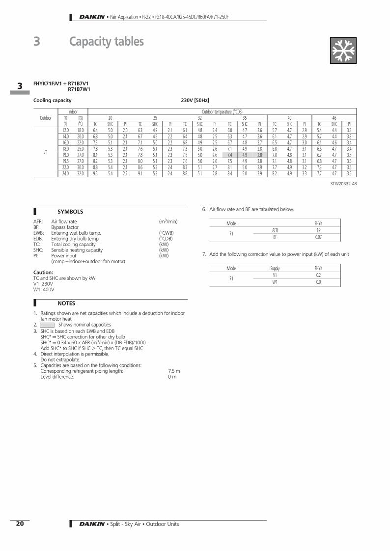
Model FHYK
71AFR 19BF 0.07
7. Add the following correction value to power input (kW) of each unit
Model Supply FHYK
71V1 0.2W1 0.0
FHYK71FJV1 + R71B7V1R71B7W1
Cooling capacity 230V [50Hz]
OutdoorIndoor Outdoor temperature (°CDB)
EWB(°C)
EDB(°C)
20 25 32 35 40 46TC SHC PI TC SHC PI TC SHC PI TC SHC PI TC SHC PI TC SHC PI
71
12.0 18.0 6.4 5.0 2.0 6.3 4.9 2.1 6.1 4.8 2.4 6.0 4.7 2.6 5.7 4.7 2.9 5.4 4.4 3.314.0 20.0 6.8 5.0 2.1 6.7 4.9 2.2 6.4 4.8 2.5 6.3 4.7 2.6 6.1 4.7 2.9 5.7 4.4 3.316.0 22.0 7.3 5.1 2.1 7.1 5.0 2.2 6.8 4.9 2.5 6.7 4.8 2.7 6.5 4.7 3.0 6.1 4.6 3.418.0 25.0 7.8 5.3 2.1 7.6 5.1 2.3 7.3 5.0 2.6 7.1 4.9 2.8 6.8 4.7 3.1 6.5 4.7 3.419.0 27.0 8.1 5.3 2.1 7.8 5.1 2.3 7.5 5.0 2.6 7.4 4.9 2.8 7.0 4.8 3.1 6.7 4.7 3.519.5 27.0 8.2 5.3 2.1 8.0 5.1 2.3 7.6 5.0 2.6 7.5 4.9 2.8 7.1 4.8 3.1 6.8 4.7 3.522.0 30.0 8.8 5.4 2.1 8.6 5.3 2.4 8.3 5.1 2.7 8.1 5.0 2.9 7.7 4.9 3.2 7.3 4.7 3.524.0 32.0 9.5 5.4 2.2 9.1 5.3 2.4 8.8 5.1 2.8 8.4 5.0 2.9 8.2 4.9 3.3 7.7 4.7 3.5
3TW20332-4B
• Pair Application • R-22 • RE18-40GA/R25-45DC/R60FA/R71-250F
3 Capacity tables
163
20 • Split - Sky Air • Outdoor Units

SYMBOLS
AFR: Air flow rate (m3/min)BF: Bypass factorEWB: Entering wet bulb temp. (°CWB)EDB: Entering dry bulb temp. (°CDB)TC: Total cooling capacity (kW)SHC: Sensible heating capacity (kW)PI: Power input (kW)
(comp.+indoor+outdoor fan motor)
Caution:TC and SHC are shown by kWV1: 230VW1: 400V
NOTES
1. Ratings shown are net capacities which include a deduction for indoorfan motor heat
2. Shows nominal capacities3. SHC is based on each EWB and EDB
SHC* = SHC correction for other dry bulbSHC* = 0.34 x 60 x AFR (m3/min) x (DB-EDB)/1000.Add SHC* to SHC if SHC > TC, then TC equal SHC
4. Direct interpolation is permissible.Do not extrapolate.
5. Capacities are based on the following conditions:Corresponding refrigerant piping length: 7.5 mLevel difference: 0 m
6. Air flow rate and BF are tabulated below.
Model FHYC
71AFR 18BF 0.10
100AFR 28BF 0.16
125AFR 31BF 0.07
7. Add the following correction value to power input (kW) of each unit
Model Supply FHYC
71V1 0.2W1 0.0
100V1 0.3W1 0.0
125 W1 0.0
FHYC71∼125 + R71∼100B7V1R71∼125B7W1
Cooling capacity 230V [50Hz]
OutdoorIndoor Outdoor temperature (°CDB)
EWB(°C)
EDB(°C)
20 25 32 35 40 46TC SHC PI TC SHC PI TC SHC PI TC SHC PI TC SHC PI TC SHC PI
71
12.0 18.0 6.3 4.9 2.0 6.2 4.8 2.1 6.0 4.7 2.4 5.9 4.6 2.6 5.6 4.6 2.9 5.3 4.3 3.314.0 20.0 6.7 4.9 2.1 6.6 4.8 2.2 6.3 4.7 2.5 6.2 4.6 2.6 6.0 4.6 2.9 5.6 4.3 3.316.0 22.0 7.2 5.0 2.1 7.0 4.9 2.2 6.7 4.8 2.5 6.6 4.7 2.7 6.4 4.6 3.0 6.0 4.5 3.418.0 25.0 7.7 5.2 2.1 7.5 5.0 2.3 7.2 4.9 2.6 7.0 4.8 2.8 6.7 4.6 3.1 6.4 4.6 3.419.0 27.0 8.0 5.2 2.1 7.7 5.0 2.3 7.4 4.9 2.6 7.3 4.8 2.8 6.9 4.7 3.1 6.6 4.6 3.519.5 27.0 8.1 5.2 2.1 7.9 5.0 2.3 7.5 4.9 2.6 7.4 4.8 2.8 7.0 4.7 3.1 6.7 4.6 3.522.0 30.0 8.7 5.3 2.1 8.5 5.2 2.4 8.2 5.0 2.7 8.0 4.9 2.9 7.6 4.8 3.2 7.2 4.6 3.524.0 32.0 9.4 5.3 2.2 9.0 5.2 2.4 8.7 5.0 2.8 8.3 4.9 2.9 8.1 4.8 3.3 7.6 4.6 3.5
100
12.0 18.0 8.9 7.2 2.5 8.7 7.1 2.7 8.3 6.9 3.1 8.1 6.8 3.2 7.7 6.5 3.5 7.2 6.3 3.714.0 20.0 9.5 7.2 2.6 9.4 7.1 2.7 8.8 6.9 3.1 8.7 6.8 3.2 8.3 6.5 3.6 7.8 6.3 3.716.0 22.0 10.2 7.4 2.6 9.9 7.2 2.8 9.5 7.0 3.1 9.2 6.9 3.3 8.8 6.7 3.6 8.3 6.4 3.818.0 25.0 10.9 7.5 2.6 10.6 7.4 2.8 10.0 7.1 3.1 9.8 7.0 3.3 9.3 6.9 3.7 8.8 6.5 3.819.0 27.0 11.2 7.6 2.6 11.0 7.5 2.9 10.3 7.2 3.2 10.2 7.1 3.4 9.7 6.9 3.7 9.1 6.7 3.919.5 27.0 11.3 7.6 2.6 11.1 7.5 2.9 10.5 7.2 3.2 10.3 7.1 3.4 9.8 6.9 3.7 9.2 6.7 3.922.0 30.0 12.2 7.7 2.7 11.9 7.6 3.0 11.3 7.4 3.3 11.1 7.2 3.5 10.6 7.1 3.8 9.9 6.9 4.024.0 32.0 13.0 7.8 2.7 12.6 7.7 3.0 12.0 7.5 3.4 11.8 7.4 3.6 11.2 7.1 3.8 10.4 6.9 4.1
125
12.0 18.0 11.0 9.1 3.3 10.8 8.8 3.6 10.2 8.5 4.0 9.8 8.4 4.3 9.5 8.2 4.6 8.7 7.8 5.114.0 20.0 11.7 9.1 3.4 11.4 8.8 3.6 10.9 8.5 4.1 10.5 8.4 4.3 10.2 8.2 4.7 9.4 7.8 5.216.0 22.0 12.5 9.2 3.4 12.2 8.9 3.7 11.6 8.6 4.2 11.1 8.5 4.4 10.8 8.3 4.7 9.9 8.0 5.218.0 25.0 13.3 9.5 3.5 13.0 9.1 3.8 12.3 8.8 4.2 11.9 8.7 4.4 11.4 8.5 4.8 10.8 8.2 5.319.0 27.0 13.6 9.6 3.5 13.3 9.2 3.8 12.8 8.9 4.3 12.3 8.7 4.5 11.7 8.6 4.9 11.1 8.3 5.419.5 27.0 13.8 9.7 3.5 13.5 9.2 3.8 12.9 8.9 4.4 12.5 8.8 4.5 11.9 8.6 4.9 11.1 8.3 5.422.0 30.0 15.0 9.8 3.6 14.6 9.4 3.9 13.8 9.1 4.4 13.5 9.0 4.6 12.9 8.7 5.0 12.1 8.5 5.524.0 32.0 15.9 9.9 3.7 15.4 9.5 4.0 14.6 9.2 4.5 14.3 9.1 4.7 13.6 8.9 5.1 12.5 8.5 5.6
3TW20332-1B
• Pair Application • R-22 • RE18-40GA/R25-45DC/R60FA/R71-250F
3 Capacity tables
163
21• Split - Sky Air • Outdoor Units

FHY71∼125BJV1 + R71∼100B7V1R71∼125B7W1
Cooling capacity 230V [50Hz]
OutdoorIndoor Outdoor temperature (°CDB)
EWB(°C)
EDB(°C)
20 25 32 35 40 46TC SHC PI TC SHC PI TC SHC PI TC SHC PI TC SHC PI TC SHC PI
71
12.0 18.0 6.3 5.0 2.0 6.2 4.9 2.1 6.1 4.8 2.4 6.0 4.7 2.6 5.7 4.6 2.9 5.4 4.3 3.314.0 20.0 6.8 5.0 2.1 6.7 4.9 2.2 6.3 4.8 2.5 6.2 4.7 2.6 6.1 4.6 2.9 5.7 4.3 3.316.0 22.0 7.3 5.1 2.1 7.1 5.0 2.2 6.8 4.9 2.5 6.7 4.8 2.7 6.4 4.7 3.0 6.1 4.5 3.418.0 25.0 7.8 5.3 2.1 7.6 5.1 2.3 7.3 5.0 2.6 7.1 4.9 2.8 6.8 4.7 3.1 6.4 4.6 3.419.0 27.0 8.1 5.3 2.1 7.8 5.1 2.3 7.5 5.0 2.6 7.4 4.9 2.8 7.0 4.8 3.1 6.7 4.6 3.519.5 27.0 8.2 5.3 2.1 8.0 5.1 2.3 7.6 5.0 2.6 7.5 4.9 2.8 7.1 4.8 3.1 6.8 4.6 3.522.0 30.0 8.8 5.4 2.1 8.6 5.3 2.4 8.3 5.1 2.7 8.1 5.0 2.9 7.7 4.9 3.2 7.3 4.7 3.524.0 32.0 9.5 5.4 2.2 9.1 5.3 2.4 8.8 5.1 2.8 8.5 5.0 2.9 8.2 4.9 3.3 7.7 4.7 3.5
100
12.0 18.0 9.0 7.3 2.5 8.8 7.2 2.7 8.3 7.0 3.1 8.1 6.9 3.2 7.7 6.6 3.5 7.3 6.4 3.714.0 20.0 9.6 7.3 2.6 9.5 7.2 2.7 8.9 7.0 3.1 8.8 6.9 3.2 8.3 6.6 3.6 7.8 6.4 3.716.0 22.0 10.3 7.5 2.6 10.0 7.3 2.8 9.6 7.1 3.1 9.3 7.0 3.3 8.9 6.8 3.6 8.3 6.5 3.818.0 25.0 11.0 7.6 2.6 10.7 7.5 2.8 10.1 7.2 3.1 9.9 7.1 3.3 9.4 7.0 3.7 8.9 6.6 3.819.0 27.0 11.3 7.7 2.6 11.1 7.6 2.9 10.4 7.3 3.2 10.3 7.2 3.4 9.8 7.0 3.7 9.2 6.8 3.919.5 27.0 11.4 7.7 2.6 11.2 7.6 2.9 10.6 7.3 3.2 10.4 7.2 3.4 9.9 7.0 3.7 9.3 6.8 3.922.0 30.0 12.4 7.7 2.7 12.0 7.7 3.0 11.4 7.5 3.3 11.2 7.3 3.5 10.7 7.2 3.8 10.0 7.0 4.024.0 32.0 13.1 7.8 2.7 12.8 7.7 3.0 12.2 7.6 3.4 11.9 7.5 3.6 11.3 7.2 3.8 10.5 7.0 4.1
125
12.0 18.0 11.0 9.2 3.3 10.9 8.9 3.6 10.3 8.5 4.0 9.9 8.4 4.3 9.6 8.2 4.6 8.8 7.8 5.114.0 20.0 11.8 9.2 3.4 11.5 8.9 3.6 10.9 8.5 4.1 10.6 8.4 4.3 10.3 8.2 4.7 9.5 7.8 5.216.0 22.0 12.6 9.3 3.4 12.3 9.0 3.7 11.7 8.7 4.2 11.2 8.5 4.4 10.9 8.3 4.7 10.0 8.0 5.218.0 25.0 13.4 9.6 3.5 13.1 9.2 3.8 12.4 8.9 4.2 12.0 8.8 4.4 11.5 8.5 4.8 10.9 8.2 5.319.0 27.0 13.8 9.7 3.5 13.4 9.3 3.8 12.9 9.0 4.3 12.4 8.8 4.5 11.8 8.7 4.9 11.1 8.3 5.419.5 27.0 14.0 9.8 3.5 13.7 9.3 3.8 13.0 9.0 4.4 12.6 8.9 4.5 12.0 8.7 4.9 11.2 8.3 5.422.0 30.0 15.1 9.9 3.6 14.7 9.5 3.9 14.0 9.2 4.4 13.7 9.1 4.6 13.0 8.8 5.0 12.2 8.5 5.524.0 32.0 16.0 10.0 3.7 15.5 9.6 4.0 14.7 9.3 4.5 14.4 9.2 4.7 13.8 9.0 5.1 12.6 8.5 5.6
3TW20332-2A
SYMBOLS
AFR: Air flow rate (m3/min)BF: Bypass factorEWB: Entering wet bulb temp. (°CWB)EDB: Entering dry bulb temp. (°CDB)ED*: Dry bulb temperature (°CDB)TC: Total cooling capacity (kW)SHC: Sensible heating capacity (kW)PI: Power input (kW)
(comp.+indoor+outdoor fan motor)
Caution:TC and SHC are shown by kWV1: 230VW1: 400V
NOTES
1. Ratings shown are net capacities which include a deduction for indoorfan motor heat
2. Shows nominal capacities3. SHC is based on each EWB and EDB
SHC* = SHC correction for other dry bulbSHC* = 0.34 x 60 x AFR (m3/min) x (DB-EDB)/1000.Add SHC* to SHC if SHC > TC, then TC equal SHC
4. Direct interpolation is permissible.Do not extrapolate.
5. Capacities are based on the following conditions:Corresponding refrigerant piping length: 7.5 mLevel difference: 0 m
6. Air flow rate and BF are tabulated below.
Model FHY
71AFR 17BF 0.1
100AFR 24BF 0.14
125AFR 30BF 0.13
7. Add the following correction value to power input (kW) of each unit
Model Supply FHY
71V1 0.1W1 0
100V1 0.2W1 0
125 W1 0
• Pair Application • R-22 • RE18-40GA/R25-45DC/R60FA/R71-250F
3 Capacity tables
163
22 • Split - Sky Air • Outdoor Units

SYMBOLS
AFR: Air flow rate (m3/min)BF: Bypass factorEWB: Entering wet bulb temp. (°CWB)EDB: Entering dry bulb temp. (°CDB)TC: Total cooling capacity (kW)SHC: Sensible heating capacity (kW)PI: Power input (kW)
(comp.+indoor+outdoor fan motor)
Caution:TC and SHC are shown by kWV1: 230VW1: 400V
NOTES
1. Ratings shown are net capacities which include a deduction for indoorfan motor heat
2. Shows nominal capacities3. SHC is based on each EWB and EDB
SHC* = SHC correction for other dry bulbSHC* = 0.34 x 60 x AFR (m3/min) x (DB-EDB)/1000.Add SHC* to SHC if SHC > TC, then TC equal SHC
4. Direct interpolation is permissible.Do not extrapolate.
5. Capacities are based on the following conditions:Corresponding refrigerant piping length: 7.5 mLevel difference: 0 m
6. Air flow rate and BF are tabulated below.
Model FHYB
71AFR 19BF 0.11
100AFR 27BF 0.20
125AFR 35BF 0.14
7. Add the following correction value to power input (kW) of each unit
Model Supply FHYB
71V1 0.2W1 0.0
100V1 0.3W1 0.0
125 W1 0.0
FHYB71∼125FK7V1 + R71∼100B7V1R71∼125B7W1
Cooling capacity 230V [50Hz]
OutdoorIndoor Outdoor temperature (°CDB)
EWB(°C)
EDB(°C)
20 25 32 35 40 46TC SHC PI TC SHC PI TC SHC PI TC SHC PI TC SHC PI TC SHC PI
71
12.0 18.0 6.2 4.9 2.0 6.1 4.8 2.2 5.9 4.7 2.5 5.8 4.6 2.7 5.5 4.5 3.0 5.2 4.2 3.414.0 20.0 6.6 4.9 2.1 6.5 4.8 2.3 6.2 4.7 2.6 6.1 4.6 2.7 5.9 4.5 3.0 5.5 4.2 3.416.0 22.0 7.1 5.0 2.1 6.9 4.9 2.3 6.6 4.8 2.6 6.5 4.7 2.8 6.3 4.6 3.1 5.9 4.4 3.518.0 25.0 7.6 5.1 2.1 7.4 5.0 2.4 7.1 4.9 2.7 6.9 4.8 2.9 6.6 4.6 3.2 6.3 4.5 3.519.0 27.0 7.9 5.1 2.2 7.6 5.0 2.4 7.3 4.9 2.7 7.2 4.8 2.9 6.8 4.7 3.2 6.5 4.5 3.619.5 27.0 7.9 5.1 2.2 7.8 5.0 2.4 7.4 4.9 2.7 7.3 4.8 2.9 6.9 4.7 3.2 6.6 4.5 3.622.0 30.0 8.6 5.2 2.2 8.4 5.1 2.5 8.0 5.0 2.8 7.9 4.9 3.0 7.5 4.8 3.3 7.1 4.6 3.724.0 32.0 9.3 5.2 2.3 8.9 5.1 2.5 8.6 5.0 2.9 8.2 4.9 3.0 7.9 4.8 3.4 7.5 4.6 3.7
100
12.0 18.0 9.2 7.4 2.5 9.0 7.3 2.8 8.5 7.1 3.2 8.3 7.0 3.3 7.9 6.7 3.6 7.4 6.5 3.814.0 20.0 9.8 7.4 2.6 9.7 7.3 2.8 9.1 7.1 3.2 9.0 7.0 3.3 8.5 6.7 3.7 8.0 6.5 3.916.0 22.0 10.5 7.6 2.6 10.2 7.4 2.9 9.8 7.2 3.2 9.5 7.1 3.4 9.1 6.9 3.7 8.5 6.6 3.918.0 25.0 11.2 7.7 2.7 10.9 7.6 2.9 10.3 7.3 3.2 10.1 7.2 3.4 9.6 7.1 3.8 9.1 6.7 3.919.0 27.0 11.5 7.8 2.7 11.3 7.7 3.0 10.6 7.4 3.3 10.5 7.3 3.5 10.0 7.1 3.8 9.4 6.9 4.019.5 27.0 11.6 7.8 2.7 11.4 7.7 3.0 10.8 7.4 3.3 10.6 7.3 3.5 10.1 7.1 3.9 9.5 6.9 4.022.0 30.0 12.6 7.9 2.8 12.2 7.8 3.1 11.6 7.6 3.4 11.4 7.4 3.6 10.9 7.3 3.9 10.2 7.1 4.124.0 32.0 13.4 8.0 2.8 13.0 7.9 3.1 12.4 7.7 3.5 12.1 7.6 3.7 11.5 7.3 3.9 10.7 7.1 4.2
125
12.0 18.0 11.0 9.2 3.3 10.9 8.9 3.7 10.3 8.5 4.1 9.9 8.4 4.4 9.6 8.2 4.7 8.8 7.8 5.214.0 20.0 11.8 9.2 3.5 11.5 8.9 3.7 10.9 8.5 4.2 10.6 8.4 4.4 10.3 8.2 4.8 9.5 7.8 5.316.0 22.0 12.6 9.3 3.5 12.3 9.0 3.8 11.7 8.7 4.3 11.2 8.5 4.5 10.9 8.3 4.8 10.0 8.0 5.318.0 25.0 13.4 9.6 3.6 13.1 9.2 3.9 12.4 8.9 4.3 12.0 8.8 4.5 11.5 8.5 4.9 10.9 8.2 5.419.0 27.0 13.8 9.7 3.6 13.4 9.3 3.9 12.9 9.0 4.4 12.4 8.8 4.6 11.8 8.7 5.0 11.1 8.3 5.519.5 27.0 14.0 9.8 3.6 13.7 9.3 3.9 13.0 9.0 4.5 12.6 8.9 4.6 12.0 8.7 5.0 11.2 8.3 5.522.0 30.0 15.1 9.9 3.7 14.7 9.5 4.0 14.0 9.2 4.5 13.7 9.1 4.7 13.0 8.8 5.1 12.2 8.5 5.624.0 32.0 16.0 10.0 3.8 15.5 9.6 4.1 14.7 9.3 4.6 14.4 9.2 4.8 13.8 9.0 5.2 12.6 8.5 5.8
3TW20332-3B
• Pair Application • R-22 • RE18-40GA/R25-45DC/R60FA/R71-250F
3 Capacity tables
163
23• Split - Sky Air • Outdoor Units

FAY71∼100FJV1 + R71∼100B7V1R71∼125B7W1
Cooling capacity 230V [50Hz]
OutdoorIndoor Outdoor temperature (°CDB)
EWB(°C)
EDB(°C)
20 25 32 35 40 46TC SHC PI TC SHC PI TC SHC PI TC SHC PI TC SHC PI TC SHC PI
71
12.0 18.0 6.4 5.0 2.1 6.3 4.9 2.2 6.1 4.8 2.5 6.0 4.7 2.7 5.7 4.7 3.0 5.4 4.4 3.414.0 20.0 6.8 5.0 2.2 6.7 4.9 2.3 6.4 4.8 2.6 6.3 4.7 2.7 6.1 4.7 3.0 5.7 4.4 3.416.0 22.0 7.3 5.1 2.2 7.1 5.0 2.3 6.8 4.9 2.6 6.7 4.8 2.8 6.5 4.7 3.1 6.1 4.6 3.518.0 25.0 7.8 5.3 2.2 7.6 5.1 2.4 7.3 5.0 2.7 7.1 4.9 2.9 6.8 4.7 3.2 6.5 4.7 3.519.0 27.0 8.1 5.3 2.2 7.8 5.1 2.4 7.5 5.0 2.7 7.4 4.9 2.9 7.0 4.8 3.2 6.7 4.7 3.619.5 27.0 8.2 5.3 2.2 8.0 5.1 2.4 7.6 5.0 2.7 7.5 4.9 2.9 7.1 4.8 3.2 6.8 4.7 3.622.0 30.0 8.8 5.4 2.2 8.6 5.3 2.5 8.3 5.1 2.8 8.1 5.0 3.0 7.7 4.9 3.3 7.3 4.7 3.624.0 32.0 9.5 5.4 2.3 9.1 5.3 2.5 8.8 5.1 2.9 8.4 5.0 3.0 8.2 4.9 3.4 7.7 4.7 3.6
100
12.0 18.0 8.6 7.2 2.5 8.4 7.1 2.7 8.1 6.9 3.1 7.9 6.8 3.2 7.5 6.5 3.5 7.0 6.3 3.714.0 20.0 9.2 7.2 2.6 9.1 7.1 2.7 8.5 6.9 3.1 8.4 6.8 3.2 8.1 6.5 3.6 7.6 6.3 3.716.0 22.0 9.9 7.4 2.6 9.6 7.2 2.8 9.2 7.0 3.1 8.9 6.9 3.3 8.5 6.7 3.6 8.1 6.4 3.818.0 25.0 10.6 7.5 2.6 10.3 7.4 2.8 9.7 7.1 3.1 9.5 7.0 3.3 9.0 6.9 3.7 8.5 6.5 3.819.0 27.0 10.9 7.6 2.6 10.7 7.5 2.9 10.0 7.2 3.2 9.9 7.1 3.4 9.4 6.9 3.7 8.8 6.7 3.919.5 27.0 11.0 7.6 2.6 10.8 7.5 2.9 10.2 7.2 3.2 10.0 7.1 3.4 9.5 6.9 3.7 8.9 6.7 3.922.0 30.0 11.8 7.7 2.7 11.6 7.6 3.0 11.0 7.4 3.3 10.8 7.2 3.5 10.3 7.1 3.8 9.6 6.9 4.024.0 32.0 12.6 7.8 2.7 12.2 7.7 3.0 11.6 7.5 3.4 11.5 7.4 3.6 10.9 7.1 3.8 10.1 6.9 4.1
3TW20332-5B
SYMBOLS
AFR: Air flow rate (m3/min)BF: Bypass factorEWB: Entering wet bulb temp. (°CWB)EDB: Entering dry bulb temp. (°CDB)TC: Total cooling capacity (kW)SHC: Sensible heating capacity (kW)PI: Power input (kW)
(comp.+indoor+outdoor fan motor)
Caution:TC and SHC are shown by kWV1: 230VW1: 400V
NOTES
1. Ratings shown are net capacities which include a deduction for indoorfan motor heat
2. Shows nominal capacities3. SHC is based on each EWB and EDB
SHC* = SHC correction for other dry bulbSHC* = 0.34 x 60 x AFR (m3/min) x (DB-EDB)/1000.Add SHC* to SHC if SHC > TC, then TC equal SHC
4. Direct interpolation is permissible.Do not extrapolate.
5. Capacities are based on the following conditions:Corresponding refrigerant piping length: 7.5 mLevel difference: 0 m
6. Air flow rate and BF are tabulated below.
Model FAY
71AFR 27BF 0.1
100AFR 27BF 0
7. Add the following correction value to power input (kW) of each unit
Model Supply FAY
71V1 0.2W1 0
100V1 0.3W1 0
• Pair Application • R-22 • RE18-40GA/R25-45DC/R60FA/R71-250F
3 Capacity tables
163
24 • Split - Sky Air • Outdoor Units

SYMBOLS
AFR: Air flow rate (m3/min)BF: Bypass factorEWB: Entering wet bulb temp. (°CWB)EDB: Entering dry bulb temp. (°CDB)TC: Total cooling capacity (kW)SHC: Sensible heating capacity (kW)PI: Power input (kW)
(comp.+indoor+outdoor fan motor)
Caution:TC and SHC are shown by kWV1: 230VW1: 400V
NOTES
1. Ratings shown are net capacities which include a deduction for indoorfan motor heat
2. Shows nominal capacities3. SHC is based on each EWB and EDB
SHC* = SHC correction for other dry bulbSHC* = 0.34 x 60 x AFR (m3/min) x (DB-EDB)/1000.Add SHC* to SHC if SHC > TC, then TC equal SHC
4. Direct interpolation is permissible.Do not extrapolate.
5. Capacities are based on the following conditions:Corresponding refrigerant piping length: 7.5 mLevel difference: 0 m
6. Air flow rate and BF are tabulated below.
Model FUY
71AFR 19BF 0.07
100AFR 29BF 0.07
125AFR 32BF 0.07
7. Add the following correction value to power input (kW) of each unit
Model Supply FUY
71V1 0.2W1 0
100V1 0.3W1 0
125 W1 0
FUY71∼125FJV1 + R71∼100B7V1R71∼125B7W1
Cooling capacity 230V [50Hz]
OutdoorIndoor Outdoor temperature (°CDB)
EWB(°C)
EDB(°C)
20 25 32 35 40 46TC SHC PI TC SHC PI TC SHC PI TC SHC PI TC SHC PI TC SHC PI
71
12.0 18.0 6.3 4.9 2.1 6.2 4.8 2.2 6.0 4.7 2.5 5.9 4.6 2.7 5.6 4.6 3.0 5.3 4.3 3.414.0 20.0 6.7 4.9 2.2 6.6 4.8 2.3 6.3 4.7 2.6 6.2 4.6 2.7 6.0 4.6 3.0 5.6 4.3 3.416.0 22.0 7.2 5.0 2.2 7.0 4.9 2.3 6.7 4.8 2.6 6.6 4.7 2.8 6.4 4.6 3.1 6.0 4.5 3.518.0 25.0 7.7 5.2 2.2 7.5 5.0 2.4 7.2 4.9 2.7 7.0 4.8 2.9 6.7 4.6 3.2 6.4 4.6 3.519.0 27.0 8.0 5.2 2.2 7.7 5.0 2.4 7.4 4.9 2.7 7.3 4.8 2.9 6.9 4.7 3.2 6.6 4.6 3.619.5 27.0 8.1 5.2 2.2 7.9 5.0 2.4 7.5 4.9 2.7 7.4 4.8 2.9 7.0 4.7 3.2 6.7 4.6 3.622.0 30.0 8.7 5.3 2.2 8.5 5.2 2.5 8.2 5.0 2.8 8.0 4.9 3.0 7.6 4.8 3.3 7.2 4.6 3.624.0 32.0 9.4 5.3 2.3 9.0 5.2 2.5 8.7 5.0 2.9 8.3 4.9 3.0 8.1 4.8 3.4 7.6 4.6 3.6
100
12.0 18.0 8.6 7.2 2.5 8.4 7.1 2.7 8.1 6.9 3.1 7.9 6.8 3.2 7.5 6.5 3.5 7.0 6.3 3.714.0 20.0 9.2 7.2 2.6 9.1 7.1 2.7 8.5 6.9 3.1 8.4 6.8 3.2 8.1 6.5 3.6 7.6 6.3 3.716.0 22.0 9.9 7.4 2.6 9.6 7.2 2.8 9.2 7.0 3.1 8.9 6.9 3.3 8.5 6.7 3.6 8.1 6.4 3.818.0 25.0 10.6 7.5 2.6 10.3 7.4 2.8 9.7 7.1 3.1 9.5 7.0 3.3 9.0 6.9 3.7 8.5 6.5 3.819.0 27.0 10.9 7.6 2.6 10.7 7.5 2.9 10.0 7.2 3.2 9.9 7.1 3.4 9.4 6.9 3.7 8.8 6.7 3.919.5 27.0 11.0 7.6 2.6 10.8 7.5 2.9 10.2 7.2 3.2 10.0 7.1 3.4 9.5 6.9 3.7 8.9 6.7 3.922.0 30.0 11.8 7.7 2.7 11.6 7.6 3.0 11.0 7.4 3.3 10.8 7.2 3.5 10.3 7.1 3.8 9.6 6.9 4.024.0 32.0 12.6 7.8 2.7 12.2 7.7 3.0 11.6 7.5 3.4 11.5 7.4 3.6 10.9 7.1 3.8 10.1 6.9 4.1
125
12.0 18.0 11.0 9.1 3.3 10.8 8.8 3.6 10.2 8.5 4.0 9.8 8.4 4.3 9.5 8.2 4.6 8.7 7.8 5.114.0 20.0 11.7 9.1 3.4 11.4 8.8 3.6 10.9 8.5 4.1 10.5 8.4 4.3 10.2 8.2 4.7 9.4 7.8 5.216.0 22.0 12.5 9.2 3.4 12.2 8.9 3.7 11.6 8.6 4.2 11.1 8.5 4.4 10.8 8.3 4.7 9.9 8.0 5.218.0 25.0 13.3 9.5 3.5 13.0 9.1 3.8 12.3 8.8 4.2 11.9 8.7 4.4 11.4 8.5 4.8 10.8 8.2 5.319.0 27.0 13.6 9.6 3.5 13.3 9.2 3.8 12.8 8.9 4.3 12.3 8.7 4.5 11.7 8.6 4.9 11.1 8.3 5.319.5 27.0 13.8 9.7 3.5 13.5 9.2 3.8 12.9 8.9 4.4 12.5 8.8 4.5 11.9 8.6 4.9 11.1 8.3 5.422.0 30.0 15.0 9.8 3.6 14.6 9.4 3.9 13.8 9.1 4.4 13.5 9.0 4.6 12.9 8.7 5.0 12.1 8.5 5.524.0 32.0 15.9 9.9 3.7 15.4 9.5 4.0 14.6 9.2 4.5 14.3 9.1 4.7 13.6 8.9 5.1 12.5 8.5 5.6
3TW20332-7B
• Pair Application • R-22 • RE18-40GA/R25-45DC/R60FA/R71-250F
3 Capacity tables
163
25• Split - Sky Air • Outdoor Units

FDY125B7V1 + R125B7W1
Cooling capacity 230V [50Hz]
OutdoorIndoor Outdoor temperature (°CDB)
EWB(°C)
EDB(°C)
20 25 32 35 40 46TC SHC PI TC SHC PI TC SHC PI TC SHC PI TC SHC PI TC SHC PI
125
12 18 11.1 9.6 3.6 10.8 9.4 4.0 10.2 9.0 4.5 10.0 8.8 4.8 9.5 8.5 5.2 8.9 8.1 5.814 20 11.9 9.7 3.7 11.5 9.5 4.0 10.9 9.1 4.6 10.6 8.9 4.8 10.1 8.6 5.3 9.5 8.2 5.916 22 12.6 9.8 3.8 12.2 9.5 4.1 11.6 9.2 4.7 11.3 9.0 4.9 10.8 8.7 5.4 10.1 8.3 6.018 25 13.5 10.4 3.9 13.0 10.1 4.2 12.3 9.7 4.8 12.0 9.6 5.0 11.5 9.2 5.5 10.8 8.8 6.119 27 13.9 9.5 3.9 13.4 10.7 4.3 12.7 10.3 4.8 12.4 10.1 5.1 11.8 9.8 5.6 11.1 9.4 6.222 30 15.2 9.7 4.1 14.7 10.7 4.4 13.9 10.3 5.0 13.6 10.1 5.3 13.0 9.8 5.8 12.2 9.4 6.424 32 16.1 9.8 4.2 15.6 10.6 4.5 14.8 10.2 5.1 14.4 10.1 5.4 13.7 9.8 5.9 12.9 9.4 6.5
3TW20372-6A
SYMBOLS
AFR: Air flow rate (m3/min)BF: Bypass factorEWB: Entering wet bulb temp. (°CWB)EDB: Entering dry bulb temp. (°CDB)DB*: Dry bulb temperature (°CDB)TC: Total cooling capacity (kW)SHC: Sensible heating capacity (kW)PI: Power input (kW)
(comp.+indoor+outdoor fan motor)
Caution:TC and SHC are shown by kWV1: 230VW1: 400V
NOTES
1. Ratings shown are net capacities which include a deduction for indoorfan motor heat
2. Shows nominal capacities3. SHC is based on each EWB and EDB
SHC* = SHC correction for other dry bulbSHC* = 0.34 x 60 x AFR (m3/min) x (DB-EDB)/1000.Add SHC* to SHC if SHC > TC, then TC equal SHC
4. Direct interpolation is permissible.Do not extrapolate.
5. Capacities are based on the following conditions:Corresponding refrigerant piping length: 7.5 mLevel difference: 0 m
6. Air flow rate and BF are tabulated below.
Model FDY
125AFR 45BF 0.25
• Pair Application • R-22 • RE18-40GA/R25-45DC/R60FA/R71-250F
3 Capacity tables
163
26 • Split - Sky Air • Outdoor Units

FDY200∼250F7V1 + R200∼250F7V1
Cooling capacity 230V [50Hz]
Model FDY200 FDY250AFR 72 90BF 0.25 0.25
OutdoorIndoor Outdoor temperature (°CDB)
EWB(°C)
EDB(°C)
20 25 32 35 40 46TC SHC PI TC SHC PI TC SHC PI TC SHC PI TC SHC PI TC SHC PI
200
12 18 17.9 15.7 6.1 17.2 15.2 6.5 16.2 14.5 7.3 15.8 14.2 7.7 15.1 13.8 8.4 14.4 13.3 9.414 20 19.2 15.8 6.1 18.4 15.3 6.6 17.4 14.6 7.4 16.9 14.4 7.8 16.3 13.9 8.5 15.5 13.4 9.516 22 20.5 15.9 6.2 19.7 15.4 6.7 18.6 14.7 7.5 18.1 14.5 7.9 17.4 14.0 8.7 16.7 13.5 9.718 25 21.8 16.8 6.3 21.0 16.4 6.8 19.8 15.7 7.6 19.4 15.5 8.0 18.6 15.0 8.8 17.8 14.5 9.819 27 22.5 17.8 6.4 21.6 17.3 6.9 20.5 16.7 7.7 20.0 16.4 8.1 19.3 16.0 8.9 18.4 15.5 9.922 30 24.7 17.8 6.5 23.8 17.3 7.0 22.6 16.7 7.9 22.0 16.4 8.3 21.2 16.0 9.1 20.3 15.5 10.124 32 26.2 17.8 6.7 25.3 17.3 7.2 24.0 16.7 8.0 23.5 16.4 8.5 22.7 16.0 9.3 21.7 15.5 10.3
250
12 18 21.7 18.9 7.0 20.8 18.3 7.6 19.6 17.5 8.5 19.1 17.2 8.9 18.3 16.6 9.8 17.5 16.0 10.914 20 23.2 19.0 7.1 22.3 18.4 7.7 21.0 17.7 8.6 20.5 17.3 9.0 19.7 16.8 9.9 18.8 16.2 11.116 22 24.8 19.1 7.2 23.8 18.6 7.8 22.5 17.8 8.7 21.9 17.5 9.2 21.1 17.0 10.0 20.2 16.4 11.218 25 26.4 20.3 7.3 25.4 19.7 7.9 24.0 19.0 8.9 23.4 18.7 9.3 22.5 18.1 10.2 21.6 17.6 11.419 27 27.2 21.5 7.4 26.2 20.9 8.0 24.8 20.1 8.9 24.2 19.8 9.4 23.3 19.3 10.3 22.3 18.7 11.522 30 29.9 21.4 7.6 28.8 20.9 8.2 27.3 20.1 9.2 26.7 19.8 9.7 25.7 19.3 10.5 24.6 18.7 11.824 32 31.7 21.5 7.7 30.6 20.9 8.3 29.0 20.2 9.3 28.4 19.8 9.8 27.4 19.3 10.7 26.2 18.7 12.0
3TW21482-1
SYMBOLS
AFR: Air flow rate (m3/min)BF: Bypass factorEWB: Entering wet bulb temp. (°CWB)EDB: Entering dry bulb temp. (°CDB)TC: Total cooling capacity (kW)SHC: Sensible heating capacity (kW)PI: Power input (kW)
(comp.+indoor+outdoor fan motor)
Caution:TC and SHC are shown by kWV1: 230VW1: 400V
NOTES
1. Ratings shown are net capacities which include a deduction for indoorfan motor heat
2. Shows nominal capacities3. SHC is based on each EWB and EDB
SHC* = SHC correction for other dry bulbSHC* = 0.34 x 60 x AFR (m3/min) x (DB-EDB)/1000.Add SHC* to SHC if SHC > TC, then TC equal SHC
4. Direct interpolation is permissible.Do not extrapolate.
5. Capacities are based on the following conditions:Corresponding refrigerant piping length: 7.5 mLevel difference: 0 m
• Pair Application • R-22 • RE18-40GA/R25-45DC/R60FA/R71-250F
3 Capacity tables
163
27• Split - Sky Air • Outdoor Units
4 Dimensional drawings
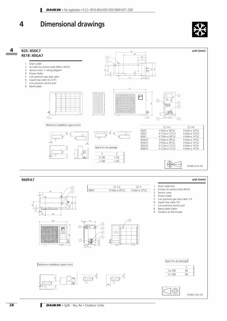
R25∼45DC7RE18∼40GA7
1 Drain outlet2 4x holes for anchor bolts (M8 or M10)3 Service cover + wiring diagram4 Power intake5 Low pressure gas stop valve6 Liquid stop valve (Cu1/4’’)7 Low pressure service port8 Name plate
j5 JA j6 JBR25DC7R35DC7R45DC7
J9.5mm or 3/8″CuTJ12.7mm or 1/2″CuTJ15.9mm or 5/8″CuT
J6.4mm or 1/4″CuTJ6.4mm or 1/4″CuTJ6.4mm or 1/4″CuT
RE18G7V1RE25G7V1RE35G7V1RE40G7V1
J9.5mm or 3/8″CuTJ9.5mm or 3/8″CuTJ12.7mm or 1/2″CuTJ12.7mm or 1/2″CuT
J6.4mm or 1/4″CuTJ6.4mm or 1/4″CuTJ6.4mm or 1/4″CuTJ6.4mm or 1/4″CuT
unit (mm)
3TW01574-1B
Space for air passage
H A≤ 1000 > 250> 1000 > 500
Minimum installation space (mm)
R60FA7
1 Drain outlet (3x)2 4 holes for anchor bolts (M10)3 Service cover4 Power intake5 Low pressure gas stop valve JA6 Liquid stop valveJB7 Low pressure service port8 Name plate Daikin9 Outdoor air thermostat
j5 JA j6 J
R60FA7 J5.9mm or 5/8″CuT J6.4mm or 1/4″CuT
unit (mm)
3TW01754-1B
Minimum installation space (mm)Space for air passage
AH ≤ 1000 300H > 1000 600
• Pair Application • R-22 • RE18-40GA/R25-45DC/R60FA/R71-250F
164
28 • Split - Sky Air • Outdoor Units

unit (mm)
1 Gas pipe connection J15.9 flare2 Liquid pipe connection - J9.5 flare3 Service port (in the unit)4 Grounding terminal M5 (in switch box)5 Drain outlet6 Stop valve cover
R71B7Hole for anchor bolt4-M12
Name plate
3TW23184-1A
unit (mm)
1 Gas pipe connection J19.1 flare2 Liquid pipe connection - J9.5 flare3 Service port (in the unit)4 Grounding terminal M5 (in switch box)5 Drain outlet6 Stop valve cover
R100-125B7Hole for anchor bolt4-M12
Name plate
3TW23224-1A
• Pair Application • R-22 • RE18-40GA/R25-45DC/R60FA/R71-250F
4 Dimensional drawings
164
29• Split - Sky Air • Outdoor Units

R200F7
1 Liquid piping connection opening2 Gas piping connection opening3 Ground terminal4 Power supply wiring outlet
unit (mm)
3TW21484-1C
(distance between foundation holes) Foundation hole
(pipes connected to the side)
Knock hole for lower piping(pipes connected tothe front)
Note: The dimensions marked withz refer to distancesafter fixing the accessory pipes.
(dist
ance
betw
een
foun
datio
nho
les)
R250F7
1 Liquid piping connection opening2 Gas piping connection opening3 Ground terminal4 Power supply wiring outlet
unit (mm)
3TW21494-1C
(distance between foundation holes) Foundation hole
(pipes connected to the side)
Knock hole for lower piping
(pipes connected tothe front)
Note: The dimensions marked withz refer to distancesafter fixing the accessory pipes.
(dist
ance
betw
een
foun
datio
nho
les)
• Pair Application • R-22 • RE18-40GA/R25-45DC/R60FA/R71-250F
4 Dimensional drawings
164
30 • Split - Sky Air • Outdoor Units

5 Operation range
RE18-40GA7
4TW01013-1
Out
door
tem
p.(°
CDB)
Pull-d
own
perio
d
Indoor temp. (°CWB)
Notes:The graph is based on the following conditions:1. Equivalent piping length 7.5 m2. Level difference 0 m
Out
door
tem
p.(°
CDB)
Pull-
dow
npe
riod
Indoor temp. (°CWB)
R25DC7R35DC7R45DC7
4TW00573-1
Notes:The graph is based on the following conditions:+ Equivalent piping length 7,5m+ Level difference 0 m+ Air flow rate Hi speed
• Pair Application • R-22 • RE18-40GA/R25-45DC/R60FA/R71-250F
165
31• Split - Sky Air • Outdoor Units
Pull-
dow
npe
riod
Indoor temp. (°CWB)
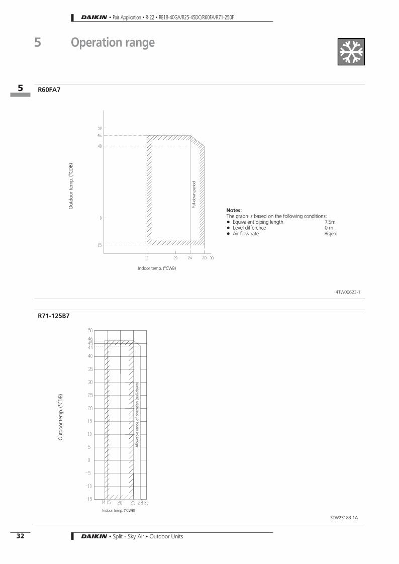
R60FA7
4TW00623-1
Notes:The graph is based on the following conditions:+ Equivalent piping length 7,5m+ Level difference 0 m+ Air flow rate Hi speed
Out
door
tem
p.(°
CDB)
Out
door
tem
p.(°
CDB)
Allo
wab
lera
nge
ofop
erat
ion
(pul
l-dow
n)
Indoor temp. (°CWB)
R71-125B7
3TW23183-1A
• Pair Application • R-22 • RE18-40GA/R25-45DC/R60FA/R71-250F
5 Operation range
165
32 • Split - Sky Air • Outdoor Units

Notes:The graph is based on the following conditions:+ Equivalent piping length 70m+ Level difference 30 m+ Air flow rate 72 m3/min
Out
door
tem
p.(°
CDB)
Pull-
dow
npe
riod
Indoor temp. (°CWB)
R200-250B7
3TW21483-1
• Pair Application • R-22 • RE18-40GA/R25-45DC/R60FA/R71-250F
5 Operation range
165
33• Split - Sky Air • Outdoor Units
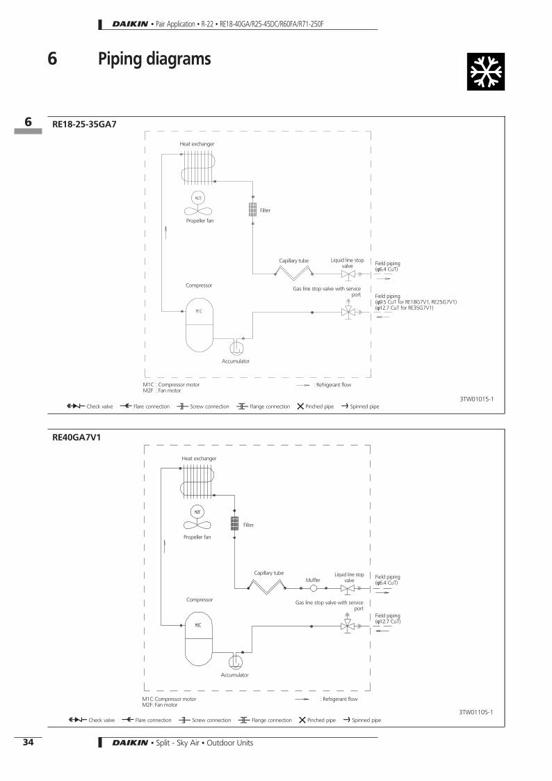
6 Piping diagrams
RE18-25-35GA7
3TW01015-1
Heat exchanger
Filter
Capillary tube Liquid line stopvalve
Field piping(φ9.5 CuT for RE18G7V1, RE25G7V1)(φ12.7 CuT for RE35G7V1)
Gas line stop valve with serviceport
Accumulator
M1C : Compressor motorM2F : Fan motor
: Refrigerant flow
O Check valve L Flare connection M Screw connection N Flange connection Z Pinched pipe P Spinned pipe
Compressor
Propeller fan
Field piping(φ6.4 CuT)
RE40GA7V1
3TW01105-1
Heat exchanger
Filter
Liquid line stopvalve
Field piping(φ12.7 CuT)
Gas line stop valve with serviceport
Accumulator
M1C: Compressor motorM2F: Fan motor
: Refrigerant flow
O Check valve L Flare connection M Screw connection N Flange connection Z Pinched pipe P Spinned pipe
Compressor
Propeller fan
Capillary tubeField piping(φ6.4 CuT)Muffler
• Pair Application • R-22 • RE18-40GA/R25-45DC/R60FA/R71-250F
166
34 • Split - Sky Air • Outdoor Units

R25-35-45DC7
3TW00025-1A
Heat exchanger
Filter
Capillary tube Liquid line stopvalve
Field piping(φ9.5 CuT for R25DB7V1)(φ12.7 CuT for R35DB7V1)(φ15.9 CuT for R45DB7V1/W1)
Gas line stop valve with serviceport
Accumulator
M1C : Compressor motorM2F : Fan motor
→ : Refrigerant flow
O Check valve L Flare connection M Screw connection N Flange connection Z Pinched pipe P Spinned pipe
Compressor
Propeller fan
Field piping(φ6.4 CuT)
Service port
R60FA7
3TW00625-1C
Heat exchanger
Filter
Capillary tube
Liquid line stopvalve
(φ15.9 CuT)
Gas line stop valve withservice port
Accumulator
M1C : Compressor motorM2F : Fan motor
S2PH : High pressure switch→ : Refrigerant flow
O Check valve L Flare connection M Screw connection N Flange connection Z Pinched pipe P Spinned pipe
Compressor
Propeller fanField piping(φ6.4 CuT)
Service port
• Pair Application • R-22 • RE18-40GA/R25-45DC/R60FA/R71-250F
6 Piping diagrams
166
35• Split - Sky Air • Outdoor Units

Capillary tube
Electronic expansionvalve
Filter
Outdoor heat exchanger
Field pipingJ9.5 C122OT-O
Field pipingJ15.9 C122OT-O
Indoor unit
Stop valve(with service port 1/4 ’ flare)
Outdoor unit
Service port 1/4’’
Filter
Pressureswitch (low)
Pressure switch(high)
Filter
Indoor heat exchanger
Compressor
3TW23185-1
R71B7
Capillary tube
Electronic expansionvalve
Filter
Outdoor heat exchanger
Field pipingJ9.5 C122OT-O
Field pipingJ15.9 C122OT-O
Indoor unit
Stop valve(with service port 1/4 ’ flare)
Outdoor unit
Service port 1/4’’
Filter
Pressureswitch (low)
Pressure switch(high)
Filter
Indoor heat exchanger
Compressor
3TW23225-1
R100-125B7
• Pair Application • R-22 • RE18-40GA/R25-45DC/R60FA/R71-250F
6 Piping diagrams
166
36 • Split - Sky Air • Outdoor Units

Capillary tube
Filter
Outdoor heat exchanger
Field pipingJ A
Field pipingJ B
Indoor unit Stop valve(with service port 1/4 ’ flare)
Outdoor unit
Service port 1/4’’
Accumulator
Pressureswitch (low)
Pressure switch(high)
Fan
Indoor heat exchanger
Compressor
3TW21485-1A
A B Model12.7 28.6 R20015.9 28.6 R250
R200-250F7
Propeller fan
• Pair Application • R-22 • RE18-40GA/R25-45DC/R60FA/R71-250F
6 Piping diagrams
166
37• Split - Sky Air • Outdoor Units

7 Wiring diagrams
RE18GA7
3TW01016-1A
Outdoor
Indoor
C1R,C2R : Running capacitorF1U : Field fuseF2S : Surge absorberK1M : Compressor contactorM1C : Compressor motorM2F : Fan motor
L LiveN NeutralR Protective earth
g Field wiring
Q1CL : Overcurrent overload switch (compressor)Q3M : Thermal protectorQ5E : Field earth leak protectorX1M : Terminal strip
RE40GA7
3TW01036-1B
Outdoor
Indoor
C1R,C2R : Running capacitorF1U : Field fuseF2S : Surge absorberK1M : Compressor contactorM1C : Compressor motorM2F : Fan motor
L LiveN NeutralR Protective earth
g Field wiring
Q2L : Overload switch (compressor)Q3M,Q4M : Thermal protectorQ5E : Field earth leak protectorX1M : Terminal stripX2A : Connector
• Pair Application • R-22 • RE18-40GA/R25-45DC/R60FA/R71-250F
167
38 • Split - Sky Air • Outdoor Units

R25DC7
3TW00576-1B
Outdoor
Indoor
C1R,C2R : Running capacitorF1U : Field fuseF2S : Surge absorberK1M : Compressor contactorM1C : Compressor motorM2F : Fan motor
L LiveN NeutralR Protective earth
g Field wiring
Q1CL : Overcurrent overload switch (compressor)Q3M : Thermal protectorQ5E : Field earth leak protector
S1T : ThermostatX1M : Terminal stripX2A : ConnectorZ1F : Noise filter
R35DC7
3TW00596-1D
Outdoor
Indoor
C1R,C2R : Running capacitorF1U : Field fuseF2S : Surge absorberK1M : Compressor contactorM1C : Compressor motorM2F : Fan motor
L LiveN NeutralR Protective earth
g Field wiring
Q2L : Overload protector (compressor)Q3M,Q4M : Thermal protectorQ5E : Field earth leak protector
S1T : ThermostatX1M : Terminal stripX2A : ConnectorZ1F : Noise filter
• Pair Application • R-22 • RE18-40GA/R25-45DC/R60FA/R71-250F
7 Wiring diagrams
167
39• Split - Sky Air • Outdoor Units

R45DC7
3TW00606-1A
Outdoor
Indoor
C1R,C2R : Running capacitorF1U : Field fuseF2S,F3S : Surge absorberK1M : Compressor contactorM1C : Compressor motorM2F : Fan motor
L LiveN NeutralR Protective earth
g Field wiring
Q2L : Overload protector (compressor)Q3M,Q4M : Thermal protectorQ5E : Field earth leak protector
S1T : ThermostatX1M : Terminal stripX2A : ConnectorZ1F : Noise filter
R45DC7
3TW00616-1C
Outdoor
Indoor
C2R : Running capacitorF1U : Field fuseF2S, F35 : Surge absorberK1M : Compressor contactorM1C : Compressor motorM2F : Fan motor
N NeutralL1,L2,L3 LiveR Protective earth
g Field wiring
Q3M : Thermal protectorQ5E : Field earth leak protectorQ2L : Overload protector (compressor)F3C : Overcurrent relayK2R : Magnetic relayR1P : Reverse phase protector
S1T : ThermostatX1M : Terminal stripX2A : ConnectorZ1F : Noise filter
• Pair Application • R-22 • RE18-40GA/R25-45DC/R60FA/R71-250F
7 Wiring diagrams
167
40 • Split - Sky Air • Outdoor Units

R60FA7V1
3TW01126-1B
Outdoor
Indoor
C1R : Running capacitorFU : FuseF1U : Field fuseSA : Surge absorberK1M : Compressor contactorM1C : Compressor motorM2F : Fan motor
L LiveN NeutralR Protective earth
g Field wiring
Q3M,Q4M : Thermal protectorQ5E : Field earth leak protectorSA : Surge absorberMR1,MR2 : Magnetic relayPCB : Printed circuit boardQ2L : Overload protector
X1M : Terminal stripR1T : ThermistorS1∼S5 : ConnectorX11A,X12A : ConnectorS2PH : High pressure switchT1R : Transformer
Room A
R60FA7W1
3TW01136-1D
Outdoor
Indoor
C2R : Running currentCT1,CT2 : Current transformerFU1∼FU3 : FuseF1U : Field fuseK1M : Compressor contactorM1C : Compressor motor
L1∼L3 LiveN NeutralR Protective earth
g Field wiring
M2F : Fan motorMRoc : Magnetic relayPCB : Printed circuit boardQ2L : Overload protectorQ3M,Q4M : Thermal protectorQ5E : Field earth leak protector
SA : Surge absorberS1T : ThermostatS2PH : High pressure switchX1M : Terminal stripZ1F : Noise filterS1,S2,S4,S5,S10,X11A : Connector
Room A
• Pair Application • R-22 • RE18-40GA/R25-45DC/R60FA/R71-250F
7 Wiring diagrams
167
41• Split - Sky Air • Outdoor Units

2TW23186-1A
R71B7
A1P,A2P Printed circuit boardBS1 Push button (pump down)C1R Capacitor (M1F)C3R,C4R Capacitor (M1C)F1C Overcurrent relay (M1C)F1U Fuse (250V, 5A)
F3U Field fuseH1P LED (service monitor green)H2P,H3P LED (service monitor red)J1HC Crankcase heaterK1M Magnetic contactor (M1C)M1C Motor (compressor)M1F Motor (fan)
Q1L Thermo switch (M1F)Q3E Earth leak detectorR1T Thermistor (air)R2T Thermistor (coil)R3T Thermistor (discharge pipe)RC Signal receiver circuitRyC Magnetic relay (K1M)
RyF1-3 Magnetic relay (M1F)S1LP Pressure switch (low)S1PH Pressure switch (high)SD Safety devices inputSS1 Selector switch (emergency)T1R Transformer (220-240V/16V)TC Signal transmission circuitX1M Terminal stripY1E Expansion valve (electronic type)
Indoor
Note:
Do not operate the unit by short-circuiting S1LP
g Field wiringD : TerminalF : Connector„ : Wire clampb : Protective earth (screw)
ColoursBLK: Black/ BLU: Blue/ WHT: White/RED: Red/ ORG: Orange/ YLW:Yellow
Switch box
OutdoorL-RED N-BLU
2TW23196-1
R71B7
A1P,A2P Printed circuit boardBS1 Push button (pump down)C1R Capacitor (M1F)F1C Overcurrent relay (M1C)F1U,F2U Fuse (250V, 5A)F3U Field fuseH1P Light emitting diode (service monitor green)
H2P,H3P Light emitting diode (service monitor red)J1HC Crankcase heaterK1M Magnetic contactor (M1C)M1C Motor (compressor)M1F Motor (fan)PRC Phase reverse circuitQ1L Thermo switch (M1F)Q3E Earth leak detector
R1T Thermistor (air)R2T Thermistor (coil)R3T Thermistor (discharge pipe)RC Signal receiver circuitRyC Magnetic relay (K1M)RyF1-3 Magnetic relay (M1F)S1LP Pressure switch (low)S1PH Pressure switch (high)
SD Safety devices inputSS1 Selector switch (emergency)T1R Transformer (220-240V/16V)TC Signal transmission circuitX1M Terminal stripY1E Expansion valve (electronic type)
Indoor
Note:
Do not operate the unit by short-circuiting S1LP
g Field wiringD : TerminalF : Connector„ : Wire clampb : Protective earth (screw)
ColoursBLK: Black/ BLU: Blue/ WHT: White/RED: Red/ ORG: Orange/ YLW:Yellow
Switch box
Outdoor
L-RED L2-WHT L3-BLK N-BLU
• Pair Application • R-22 • RE18-40GA/R25-45DC/R60FA/R71-250F
7 Wiring diagrams
167
42 • Split - Sky Air • Outdoor Units

2TW23226-1A
R100B7
A1P,A2P Printed circuit boardBS1 Push button (pump down)C1R,C2R Capacitor (M1F-M2F)C3R,C4R Capacitor (M1C)F1C Overcurrent relay (M1C)F1U Fuse (250V, 5A)F3U Field fuse
H1P Light emitting diode (service monitor red)H2P,H3P Light emitting diode (service monitor green)J1HC Crankcase heaterK1M Magnetic contactor (M1C)M1C Motor (compressor)M1F,M2F Motor (fan)Q1L,Q2L Thermo switch (M1F, M2F)
Q3E Earth leak detectorR1T Thermistor (air)R2T Thermistor (coil)R3T Thermistor (discharge pipe)RC Signal receiver circuitRyC Magnetic relay (K1M)RyF1-4 Magnetic relay (M1F,M2F)
S1LP Pressure switch (low)S1PH Pressure switch (high)SD Safety devices inputSS1 Selector switch (emergency)T1R Transformer (220-240V/16V)TC Signal transmission circuitX1M Terminal stripY1E Expansion valve (electronic type)
Indoor
Note:
Do not operate the unit by short-circuiting S1LP
g Field wiringD : TerminalF : Connector„ : Wire clampb : Protective earth (screw)
ColoursBLK: Black/ BLU: Blue/ WHT: White/RED: Red/ ORG: Orange/ YLW:Yellow
Switch box
Outdoor
L-RED N-BLU
2TW23236-1A
R100-125B7
A1P,A2P Printed circuit boardBS1 Push button (pump down)C1R,C2R Capacitor (M1F-M2F)F1C Overcurrent relay (M1C)F1U,F2U Fuse (250V, 5A)F3U Field fuseH1P Light emitting diode (service monitor
green)
H2P,H3P Light emitting diode (service monitor red)J1HC Crankcase heaterK1M Magnetic contactor (M1C)M1C Motor (compressor)M1F,M2F Motor (fan)PRC Phase reverse circuitQ1L,Q2L Thermo switch (M1F, M2F)Q3E Earth leak detector
R1T Thermistor (air)R2T Thermistor (coil)R3T Thermistor (discharge pipe)RC Signal receiver circuitRyC Magnetic relay (K1M)RyF1-4 Magnetic relay (M1F,M2F)S1LP Pressure switch (low)S1PH Pressure switch (high)
SD Safety devices inputSS1 Selector switch (emergency)T1R Transformer (220-240V/16V)TC Signal transmission circuitX1M Terminal stripY1E Expansion valve (electronic type)
IndoorNote:
Do not operate the unit by short-circuiting S1LP
g Field wiringD : TerminalF : Connector„ : Wire clampb : Protective earth (screw)
ColoursBLK: Black/ BLU: Blue/ WHT: White/RED: Red/ ORG: Orange/ YLW:Yellow
Switch box
Outdoor
L-RED L2-WHT L3-BLK N-BLU
• Pair Application • R-22 • RE18-40GA/R25-45DC/R60FA/R71-250F
7 Wiring diagrams
167
43• Split - Sky Air • Outdoor Units

2TW21486-1A
R200-250F7
A1P,A2P Printed circuit boardBS1 Push button (pump down)C1R,C2R Capacitor (M1F-M2F)F1C Overcurrent relay (M1C)F1U,F2U Fuse (250V, 5A)F3U Field fuseH1P Light emitting diode (service monitor
green)
H2P,H3P Light emitting diode (service monitor red)J1HC Crankcase heaterK1M Magnetic contactor (M1C)M1C Motor (compressor)M1F,M2F Motor (fan)PRC Phase reverse circuitQ1L,Q2L,Q3L Thermo switch (M1F, M2F)Q3E Earth leak detector
R1T Thermistor (air)RC Signal receiver circuitRyC Magnetic relay (K1M)RyF1 Magnetic relay (M1F)S1LP Pressure switch (low)S1PH Pressure switch (high)SD Safety devices inputSS1 Selector switch (emergency)
T1R Transformer (220-240V/16V)TC Signal transmission circuitX1M Terminal strip
Indoor
Note:
Do not operate the unit by short-circuiting S1LP
g Field wiringD : TerminalF : Connector„ : Wire clampb : Protective earth (screw)
ColoursBLK: Black/ BLU: Blue/ WHT: White/RED: Red/ ORG: Orange/ YLW:Yellow
Switch box
Outdoor
L-RED L2-WHT L3-BLK N-BLU
• Pair Application • R-22 • RE18-40GA/R25-45DC/R60FA/R71-250F
7 Wiring diagrams
167
44 • Split - Sky Air • Outdoor Units

8 Sound level8-1 Sound level data
Cooling only
Model
Sound pressure level (H)
Sound power level (H)230V
Measuring location50Hz
V1 V1
RE18GA7 45 56
RE40GA7V1 50 63
Model
Sound pressure level (H)
Sound power level (H)230V 400V
Measuring location50Hz
V1 W1 V1 W1
R25DC7V11 43 − 56 −
R35DC7V11 48 − 61 −
R45DC7V11/W11 50 50 63 63
R60FA7V1/W1 54 54 67 67
Model
Sound pressure level (H)
Sound power level (H)230V 400V
Measuring location50Hz
V1 W1 V1 W1
R71B7 49 49 62 62
R100B7 52 52 64 64
R125B7 − 52 − 65
R200F7 − 56 − 77
R250F7 − 56 − 77
Note:Sound pressure level is measured in an anechoic chamber.
Center
Center
Center
• Pair Application • R-22 • RE18-40GA/R25-45DC/R60FA/R71-250F
168
8-1
45• Split - Sky Air • Outdoor Units

8 Sound level8-2 Sound pressure spectrum
Soun
dpr
essu
rele
vel[
dB(A
)]
Soun
dpr
essu
rele
vel[
dB(A
)]
Octave band center frequency (Hz) Octave band center frequency (Hz)
RE18GA7V1 RE40GA7V1
R25DC7V11 R35DC7V11
Soun
dpr
essu
rele
vel[
dB(A
)]
Soun
dpr
essu
rele
vel[
dB(A
)]
Octave band center frequency (Hz) Octave band center frequency (Hz)
Notes
– Data is valid at free field condition– Operation sound levels are valid at nominal operation condition 230V– dBA = A-weighted sound pressure level (A-scale according to IEC)– Reference acoustic pressure 0dB = 20µPa
3TW01017-1A 3TW01107-1
3TW00017-1 3TW00037-1
• Pair Application • R-22 • RE18-40GA/R25-45DC/R60FA/R71-250F
168
8-2
46 • Split - Sky Air • Outdoor Units

Soun
dpr
essu
rele
vel[
dB(A
)]
Soun
dpr
essu
rele
vel[
dB(A
)]
Octave band center frequency (Hz) Octave band center frequency (Hz)
R45DCV11 R45DC7W11
R60FA7V1 R60FA7W1
Soun
dpr
essu
rele
vel[
dB(A
)]
Soun
dpr
essu
rele
vel[
dB(A
)]
Octave band center frequency (Hz) Octave band center frequency (Hz)
Notes
– Data is valid at free field condition– Operation sound levels are valid at nominal operation condition 230V– dBA = A-weighted sound pressure level (A-scale according to IEC)– Reference acoustic pressure 0dB = 20µPa
3TW00047-1 3TW00057-1
3TW01127-1 3TW01137-1
• Pair Application • R-22 • RE18-40GA/R25-45DC/R60FA/R71-250F
8 Sound level8-2 Sound pressure spectrum
168
8-2
47• Split - Sky Air • Outdoor Units

R125FJ7W1R71FJ7V1/W1 R100FJ7V1/W1
Octave band center frequency (Hz) Octave band center frequency (Hz) Octave band center frequency (Hz)
approximate thresholdhearing for continuousnoise
approximate thresholdhearing for continuousnoise
approximate thresholdhearing for continuousnoise
Oct
ave
band
soun
dpr
essu
rele
vel
dB:(0
dB=
0.00
02µ
bar)
Oct
ave
band
soun
dpr
essu
rele
vel
dB:(0
dB=
0.00
02µ
bar)
Oct
ave
band
soun
dpr
essu
rele
vel
dB:(0
dB=
0.00
02µ
bar)
DU427-4261 DU428-4211 DU429-4178
R200F7
Soun
dpr
essu
rele
vel[
dB(A
)]
R250F7
Soun
dpr
essu
rele
vel[
dB(A
)]
3TW21497-1AOctave band center frequency (Hz)
3TW21487-1Octave band center frequency (Hz)
• Pair Application • R-22 • RE18-40GA/R25-45DC/R60FA/R71-250F
8 Sound level8-2 Sound pressure spectrum
168
8-2
48 • Split - Sky Air • Outdoor Units

9 Accessories9-1 Optional accessories
Available options for R71-125B7(V1,W1,T1)
Name of optionKit name
R71B R100B R125B
Central drain plug KKPJ5F180
Refrigerant branch pipingTwin KHRP79BA7
Triple − KHRP96H7
3TW23189-1
Available options for R200-250F7W1
Option Name of option R200F R250F
Fan motor size up NFM22C5
Fan motor size up NFM22C10 X X
Kit for discharge duct EKND26A10 X X
Refnet KHRP79BA7
Refer to the table with possible indoor combinations*Refnet KHRP102BA7
Refnet KHRP127HA7
3TW21489-2
* table with possible indoor combinations = combination matrix 3TW23619-1 (See chapter R-B7 - twin / triple / double twin application).
Liquid side joint Suction gas side joint Others
InsulatorInstallation manual
InsulatorInstallation manualOutlet
Inlet
Outlet
Inlet
Outlet
Outlet
Outlet
Outlet
Inlet
Outlet
Outlet
Inlet
Sky
Air
KHRP
79BA
7KH
RP10
2BA
7
Sky
Air
KHRP
96H
7KH
RP12
7HA
7
Liquid side joint Suction gas side header Others
InsulatorInstallation manual
InsulatorInstallation manual
Inlet
Outlet
Outlet
OutletOutlet
Inlet
Outlet
Inlet
Inlet
OutletOutlet
1TW21559-11A
• Pair Application • R-22 • RE18-40GA/R25-45DC/R60FA/R71-250F
169
9-1
49• Split - Sky Air • Outdoor Units

10 Centre of gravity
R200-250F7
4TW23619-1
Model A
R(Y)200F7W1R(Y)P200B7W1 380
R(Y)250F7W1R(Y)P250B7W1 510
• Pair Application • R-22 • RE18-40GA/R25-45DC/R60FA/R71-250F
1610
50 • Split - Sky Air • Outdoor Units
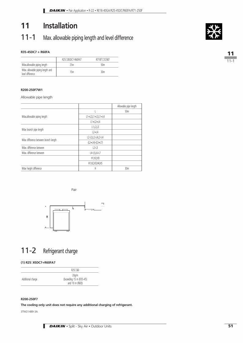
11 Installation11-1 Max. allowable piping length and level difference
R35-45DC7 + R60FA
R25∼45DC7-R60FA7 R71B7∼125B7
Max.allowable piping length 25m 50m
Max. allowable piping length andlevel difference 15m 30m
R200-250F7W1
Allowable pipe length
Allowable pipe length
Max.allowable piping length
L 50m
L1+L2,L1+L3,L1+L4
L1+L2+L4
Max branch pipe lengthL1,L2,L3
L2+L4
Max difference between branch lengthL2-L3,L2-L4,L3-L4
(L2+L4)-(L3+L7)
Max. difference between L2-L3
Max. difference between L4-L5,L6-L7
H1,H2,H3
H1,H2,H3,H4,H5
Max height difference H 30m
11-2 Refrigerant charge
(1) R25∼45DC7+R60FA7
R25∼60
Additional charge20g/m
(Exceeding 15 m (R35-45)and 10 m (R60))
R200-250F7
The cooling only unit does not require any additional charging of refrigerant.
3TW21489-3A
Pair
• Pair Application • R-22 • RE18-40GA/R25-45DC/R60FA/R71-250F
161111-1
51• Split - Sky Air • Outdoor Units
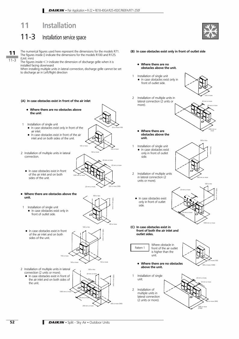
11 Installation11-3 Installation service space
+ Where there are noobstacles above the unit.
1 Installation of single unit+ In case obstacles exist only in
front of outlet side.
2 Installation of multiple units inlateral connection (2 units ormore).
+ Where there areobstacles above theunit.
1 Installation of single unit+ In case obstacles exist
only in front of outletside.
2 Installation of multiple unitsin lateral connection (2units or more).
+ In case obstacles existonly in front of outletside.
(C) In case obstacles exist infront of both the air inlet andoutlet sides.
+ Where there are no obstaclesabove the unit.
The numerical figures used here represent the dimensions for the models R71.The figures inside () indicate the dimensions for the models R100 and R125.(Unit: mm)The figures inside < > indicate the dimension of discharge grille when it isinstalled facing downwardWhen installing multiple units in lateral connection, discharge grille cannot be setto discharge air in Left/Right direction
(A) In case obstacles exist in front of the air inlet
+ In case obstacles exist in frontof the air inlet and on bothsides of the unit.
1 Installation of singleunit.
2 Installation ofmultiple units inlateral connection(2 units or more).
+ Where there are no obstacles abovethe unit
Where obstacle infront of the air outletis higher than theunit.
2 Installation of multiple units in lateralconnection (2 units or more).+ In case obstacles exist in front of
the air inlet and on both sides ofthe unit.
Pattern 1
2 Installation of multiple units in lateralconnection.
+ In case obstacles exist in frontof the air inlet and on bothsides of the unit.
+ Where there are obstacles above theunit.
1 Installation of single unit+ In case obstacles exist only in
front of outlet side.
1 Installation of single unit+ In case obstacles exist only in front of the
air inlet.+ In case obstacles exist in front of the air
inlet and on both sides of the unit.
(B) In case obstacles exist only in front of outlet side
50 or more (100)
100 or more
100 or more
100 or more
20 mm or more
20 mm or more
1000 mm or more
20 mm or more
500 or less
100 or more
500 or less
150 or more
150 or more
150 or more
500 or less
20 mm or more
1000 mm or more
20 mm or more
200 mm or more200 or more (300)
150 or more
20 mm or more
20 mm or more
1000 mm ormore
500 or less
500 mm or more
500 or less
1000 mm or more
20 mm or more
20 mm or more
50 or more (100)
500 or more (1000)
20 mm or more
20 mm or more
200 or more (300)
1000 or more(1500)
100orm
ore
1000m
morm
ore
1000m
morm
ore
1000m
morm
ore
1000m
morm
ore
200 or more (300)
• Pair Application • R-22 • RE18-40GA/R25-45DC/R60FA/R71-250F
161111-3
52 • Split - Sky Air • Outdoor Units

1 In case of installingone unit per row.
2 In case of installingmultiple units (2 unitsor more) in lateralconnection per row.
3 Installation of multiple units inlateral connection (2units or less).
Relation of dimensions of H, A, and Lare shown in the table below.
L A
L ≤ H0 < L ≤ 1/2 H 150 (250)
1/2 H < L 200 (300)H < L Set the frame to be L<=H
(D) In case of stacked installation1 In case obstacles exist in front of the
outlet side.Do not stack more than one unit.About 100mm is required as thedimension for laying the upper outdoorunit’s drain pipe.Get the portion A sealed so that air fromthe outlet does not bypass.
Relation of dimensions of H, A, and L are shown in the table below.L A
L ≤ H0 < L ≤ 1/2 H 150 (250)
1/2 H < L 200 (300)H < L Installation impossible
DU427-826
2 In case obstacles exist in front of theair inlet.
Do not stack more than one unit.
About 100mm is required as thedimension for laying the upper outdoorunit’s drain pipe.Get the portion A sealed so that air fromthe outlet does not bypass.
(E) In case of multiple-low installation(for roof top use, etc.).
+ Where there are obstacles above the unit.
+ Where there are no obstacles abovethe unit.
Get the lower part of the frame sealed so thatair from the outlet does not bypassDo not install more than 2 units
1 Installation of single unit.
2 Installation of multiple units in lateralconnection (2 units or more).
Relation of dimensions of H, A, and L areshown in the table below.
L A
L ≤ H0 < L ≤ 1/2 H 750<1250>
1/2 H < L 1000<1500>H < L Set the frame to be L<=H
Relation of dimensions of H, A, and L areshown in the table below.
L A
L ≤ H0 < L ≤ 1/2 H 1000<1500>
1/2 H < L 1250<1750>H < L Set the frame to be L<=H
Pattern 2Where obstacle in front of the air outlet islower than the unit.
1 Installation of single unit.
1 Installation of multiple units in lateral connection(2 units or more).
Relation of dimensions of H, A, and L areshown in the table below.
L A0 < L ≤ 1/2 H 150 (250)
1/2 H < L 200 (300)
+ Where there are obstacles above theunit.
1 Installation of single unit.
Relation of dimensions of H, A, and L areshown in the table below.
L A
L ≤ H0 < L ≤ 1/2 H 50 (100)
1/2 H < L 100 (200)H < L Set the frame to be L<=H
Get the lower part of the frame sealed so thatair from the outlet does not bypass
Get the lower part of the frame sealed sothat air from the outlet does not bypass
Get the lower part of the frame sealed so thatair from the outlet does not bypass
Do not install more than 2 units
500 or less
150 or more (250)
500 or less
20 mm ormore
200 or more (300)
50 or more (100)
500 or more (1000)
20 mm or more
20 mm or more
1000 or more (1500)
500 or less
500 or more (1000)
500 or less
20 mm ormore
1000 or more (1500)
20 mm or more
1000 mm or more
20 mm or more
200 or more (300)
50 or more (100)
1000 or more (2000)
100 or more (200)
500 or more (1000)
20 mm or more
20 mm or more
2000 or more (3000)
400 or more (600)
1000 or more (1500)
1000m
morm
ore
1000m
morm
ore100
ormore
1000m
morm
ore
• Pair Application • R-22 • RE18-40GA/R25-45DC/R60FA/R71-250F
11 Installation11-3 Installation service space
161111-3
53• Split - Sky Air • Outdoor Units

Single installation Installation in a row Conentrated installation
Case 1 Case 1 Case 1
Case 2 Case 2
Case 3 Case 3
Case 2
1 Case 1and case 2+ Front wall height is 1500mm+ Suction wall height is 500mm+ Side wall height has no limit+ Case 3 wall height has no limit
2 If the wall is higher than mentioned in note 1: ADO h2/2 (front side) and ANO h1/2 (suctionside) to the mentioned values for installation. (h1 and h2: see figure to the left)
3 Before installing, please check the passage of humans and air at the side, and select a placewhich is suitable for the case. (If there are a lot of units to be installed, take care that there isno shortcircuit of air)
4 Please install considering piping installation at the front side.
suct
ion
side
front
side
3TW23619-4
11 Installation11-3 Installation service space
• Pair Application • R-22 • RE18-40GA/R25-45DC/R60FA/R71-250F
•PairApplication
•R-22•RE18-40GA/R25-45DC/R60FA/R71-250F
11Installation
11-3Installationservicespace
1611
11-3
54
• Split - Sky Air • Outdoor Units
•Split-
SkyA
ir•
OutdoorU
nits

11 Installation
Do not stack more than one unitAbout 100mm is required as the dimension for laying the upper outdoor unit’s drain pipeGet the portion A sealed so that air from the outlet does not bypass
Installing multiple units (2 units or more) inlateral connection per row
Obstacles exist in front of the outlet side
Installation of one unit per row
Non stacked installation
Obstacles exist in front of the air inlet
Stacked installation
Legend
Multiple-row installation
When installing link of multiple units,leave a space of 200 mm or morebetween the casing of one unit andthe stop valves of the other unit.
Relation of dimensions of H, A, and L are shown in the table below.L A
L ≤ H0 < L ≤ 1/2 H 150 (250)
1/2 H < L 200 (300)H < L Installation impossible
3TW23189-4
Suction side obstacle
Discharge side obstacle
Left side obstacle
Right side obstacle
Top side obstacle
Obstacle is present
• Pair Application • R-22 • RE18-40GA/R25-45DC/R60FA/R71-250F
161111-3
55• Split - Sky Air • Outdoor Units

12 Safety device settings
ModelSafety device RE18GA7V1 RE40GA7V1
Fan motorThermal protector
Off 135 ±5°COn 115 ±5°C
Off 135 ±5°COn 115 ±5°C
CompressorInternal protector − Off 175 ±5°C
On 100 ±10°C
Overload relay Off 150 ±7°COn 69 ±10°C
Off 130 ±3°COn 95 ±10°C
Overcurrent relay *Off 3.6A ±12% −
4TW01011-2B + 4TW01101-2
ModelSafety device R25DC7V11 R35DC7V11 R45DC7V11 R45DC7W11
Internal protector of compressor − Off 185 ±5°COn 100 ±10°C
Off 175 ±5°COn 100 ±5°C On 86 ±15°C
Thermal protector fan Off 135 ±5°COn 115 ±5°C
Off 145 ±5°COn 75 ±5°C
Off 135 ±5°COn 115 ±5°C
Off 135 ±5°COn 115 ±5°C
Overcurrent Off 6.7A ±12°C − − Off 5A
Overload Off 150 ±7°COn 85 ±10°C
Off 130 ±3°COn 95 ±10°C
Off 130 ±3°COn 95 ±10°C
Off 130 ±3°COn 95 ±10°C
Thermostat Off 14.0 ±2°COn 16.5 ±2°C
4TW01101-2
ModelSafety device R60FA7V1 R60FA7W1
Fan motor thermal protector Off 135 ±5°COn 86 ±15°C
Off 135 ±5°COn 86 ±15°C
CompressorInternal protector
Off 170 ±5°COn 110 ±9°C −
Overload relay − Off 115 ±5°COn 85 ±7°C
Overcurrent relay − Off 7A
4TW00621-3C
• Pair Application • R-22 • RE18-40GA/R25-45DC/R60FA/R71-250F
1612
56 • Split - Sky Air • Outdoor Units


