
05 Tm Lifting Gear Issu a Rev4
11
KIAS SAFETY CONSULTANCY P.O. Box 86441 Dubai, U.A.E. Tel. 04 - 2726676 Fax 04 – 2712282 TEST METHOD THOROUGH INSPECTION OF LIFTING GEAR TEST METHOD NO. : KSC/05/TM RELATED STANDARDS : BS EN 818-4 BS EN 818-5 BS EN 818-6 BS EN 13414-1 BS EN 13414-3 BS EN 13889+A1 BS EN 1492-1 BS EN 1492-2 BS EN 1492-4 DAC REQ -06 RELATED FORMS QSP09–D–01 QSP09–D–16 QSP09–D–24 QSP09–D–26 QSP09–D–27 QSP09–D–28 QSP09–D–29 QSP09–D–30 COPY NO. : APPROVED BY : GENERAL MANAGER
-
Upload
albsam-eissa -
Category
Documents
-
view
226 -
download
0
description
05 Tm Lifting Gear Issu a Rev4
Transcript of 05 Tm Lifting Gear Issu a Rev4
KIAS SAFETY CONSULTANCY
P.O. Box 86441 Dubai, U.A.E. Tel. 04 - 2726676 Fax 04 – 2712282
TEST METHOD
THOROUGH INSPECTION OF
LIFTING GEAR
TEST METHOD NO. : KSC/05/TM
RELATED STANDARDS : BS EN 818-4 BS EN 818-5 BS EN 818-6 BS EN 13414-1 BS EN 13414-3 BS EN 13889+A1 BS EN 1492-1 BS EN 1492-2 BS EN 1492-4
DAC REQ -06
RELATED FORMS
QSP09–D–01 QSP09–D–16 QSP09–D–24
QSP09–D–26 QSP09–D–27 QSP09–D–28
QSP09–D–29 QSP09–D–30
COPY NO. : APPROVED BY : GENERAL MANAGER
KIAS SAFETY CONSULTANCY
Document Title: THOROUGH INSPECTION OF LIFTING GEAR
Test Method No. KSC/05/TM Issue A Rev. 4
Page 2 of 11 Date 28/02/2015
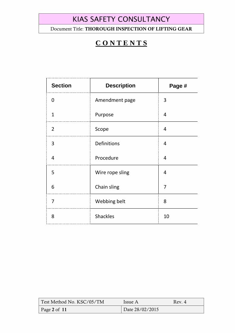
C O N T E N T S
Section Description Page #
0 Amendment page 3
1 Purpose 4
2 Scope 4
3 Definitions 4
4 Procedure 4
5 Wire rope sling 4
6 Chain sling 7
7 Webbing belt 8
8 Shackles 10
KIAS SAFETY CONSULTANCY
Document Title: THOROUGH INSPECTION OF LIFTING GEAR
Test Method No. KSC/05/TM Issue A Rev. 4
Page 3 of 11 Date 28/02/2015
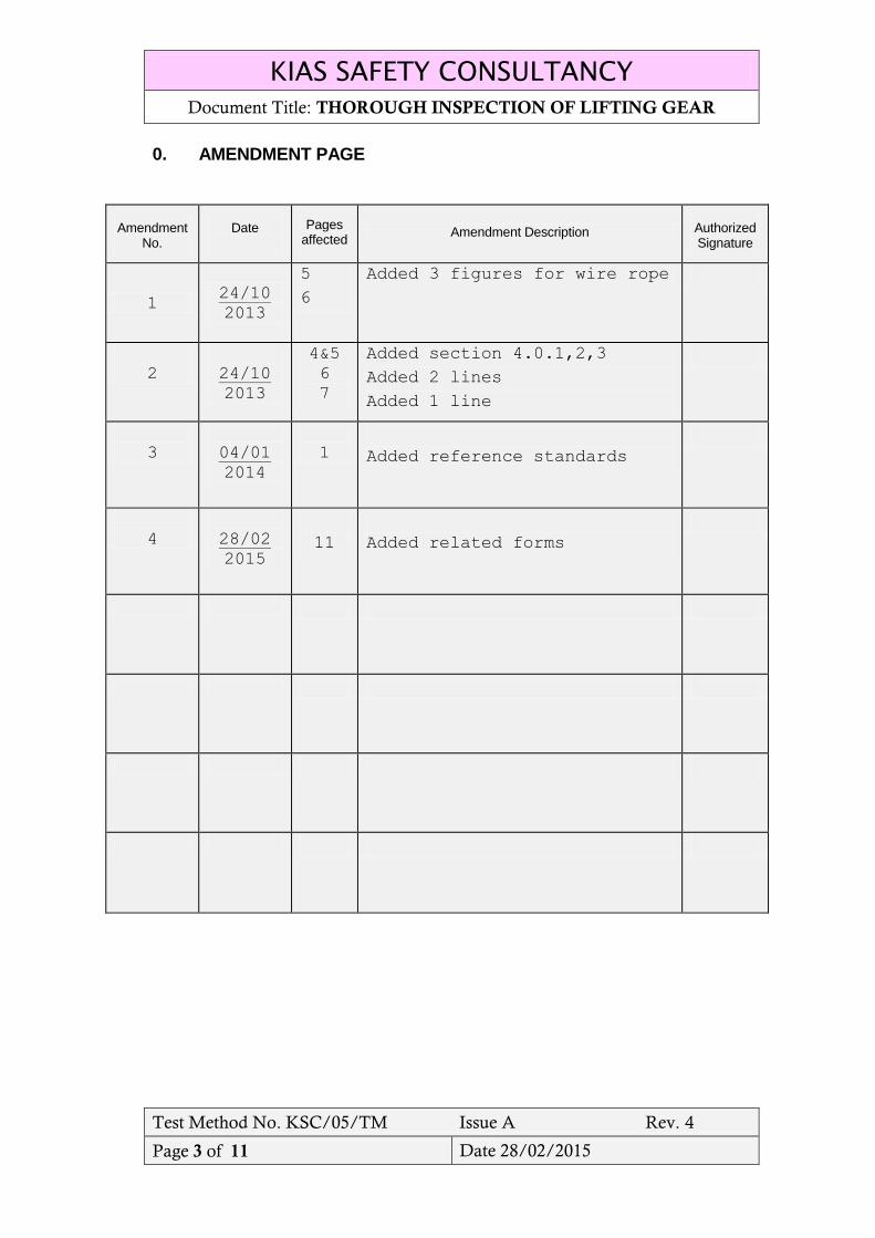
0. AMENDMENT PAGE
Amendment No.
Date
Pages affected
Amendment Description Authorized Signature
1 24/10
2013
5
6
Added 3 figures for wire rope
2
24/10
2013
4&5
6
7
Added section 4.0.1,2,3
Added 2 lines
Added 1 line
3
04/01
2014
1
Added reference standards
4
28/02
2015
11
Added related forms
KIAS SAFETY CONSULTANCY
Document Title: THOROUGH INSPECTION OF LIFTING GEAR
Test Method No. KSC/05/TM Issue A Rev. 4
Page 4 of 11 Date 28/02/2015
1.0 Purpose
The purpose of this procedure is to outline the full range of thorough
inspections required to be performed by our inspector.
2.0 Scope
This method statement covers the thorough inspection to be performed by
our inspector to satisfy the customers for inspection of chain block, chain
sling, wire rope sling, shackle and webbing sling.
3.0 Definitions:
3.1 Diameter: The length of a straight line drawn from one side to the other
through the centre of a circle.
3.2 Eyebolt: Lifting ring attached to a load.
3.3 FSWR: flexible steel wire rope sling.
3.4 Grade: Indicates the strength of chain or FSWR.
3.5 Reeve (Nip): A method of slinging where the sling passes back through
itself reducing the safe working load.
3.6 Ring: End link of a chain assembly.
3.7 Safe working load: The maximum load that can be safely lifted by a
particular sling, attachment or machine.
3.8 Shackles: Attachment for joining a sling to a load or a hook..
3.9 Sheave: A pulley through which flexible steel wire rope moves.
3.10 Sling: Lifting gear made from steel wire rope, chain or synthetics.
3.11 Spreader: A beam with a central lifting attachment that reduces the strain
on the lifting gear.
3.12 Swivel: A rotating sling attachment that rotates without spinning the wire,
hook or load.
3.13 Working Load Limit (WLL) Maximum load (mass), lifting equipment
may lift safely in the most efficient configuration. For wire rope, chain
and fiber rope slings this is in direct lift i.e. eye to eye in a straight
vertical line.
4.0 Procedure:
4.0.1 Prior to going to site, the inspector must ensure that all needed
Personnel Protective Equipment are used by him & others engaged
KIAS SAFETY CONSULTANCY
Document Title: THOROUGH INSPECTION OF LIFTING GEAR
Test Method No. KSC/05/TM Issue A Rev. 4
Page 5 of 11 Date 28/02/2015
on this activity, also he must check the critical test equipment prior to
leaving his office or before inspection.
4.0.2 the inspector shall request the manufacturing operations manual, or
maintenance manuals of the loose gear, otherwise the safe working
load charts in English and/or Arabic language and in case not
available and not possible to provide, he shall ensure that an
independent competent person be engaged by the owner to provide
advice and documentation to support the continued use of the lifting
gear sizes, grades and Markings etc.
4.0.3 the inspector shall use the tables attached to each british standards
mentioned on the cover page of this statement as rule for getting the
required values of any lifting gear for the purpose of completing the
inspection properly.
4.1 Wire Rope inspection
a) All wire ropes & slings must have a certificate of test showing size of
rope in mm. number of strands, number of wires per strand, grade of
wires, date of test and the working load limit.
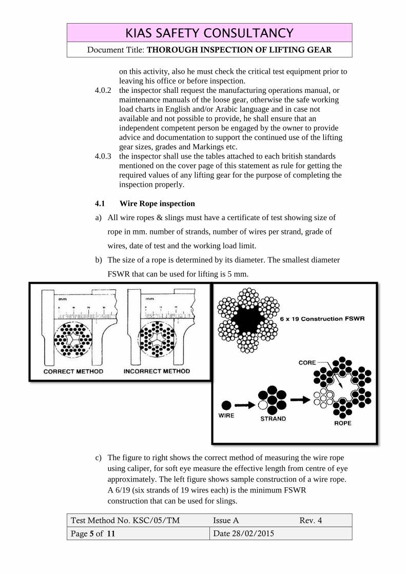
b) The size of a rope is determined by its diameter. The smallest diameter
FSWR that can be used for lifting is 5 mm.
c) The figure to right shows the correct method of measuring the wire rope
using caliper, for soft eye measure the effective length from centre of eye
approximately. The left figure shows sample construction of a wire rope.
A 6/19 (six strands of 19 wires each) is the minimum FSWR
construction that can be used for slings.
KIAS SAFETY CONSULTANCY
Document Title: THOROUGH INSPECTION OF LIFTING GEAR
Test Method No. KSC/05/TM Issue A Rev. 4
Page 6 of 11 Date 28/02/2015
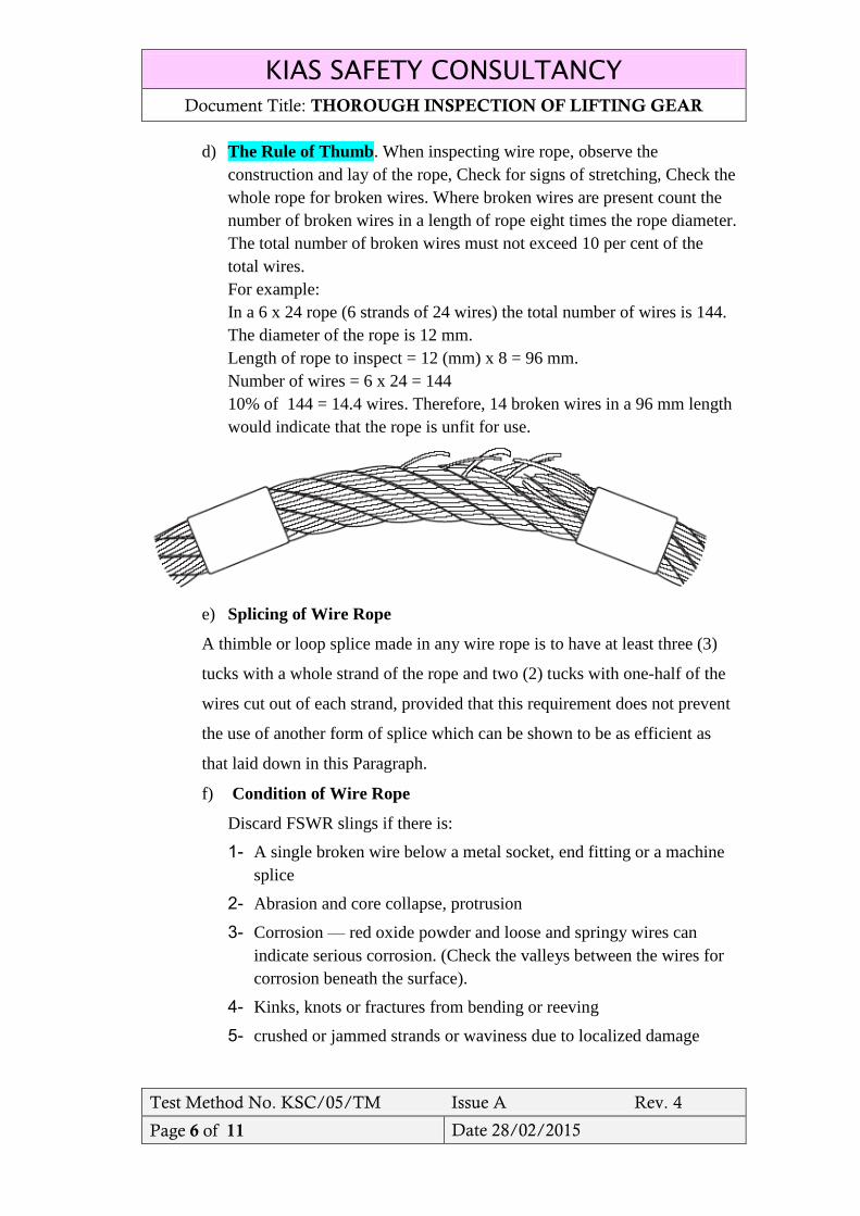
d) The Rule of Thumb. When inspecting wire rope, observe the
construction and lay of the rope, Check for signs of stretching, Check the
whole rope for broken wires. Where broken wires are present count the
number of broken wires in a length of rope eight times the rope diameter.
The total number of broken wires must not exceed 10 per cent of the
total wires.
For example:
In a 6 x 24 rope (6 strands of 24 wires) the total number of wires is 144.
The diameter of the rope is 12 mm.
Length of rope to inspect = 12 (mm) x 8 = 96 mm.
Number of wires = 6 x 24 = 144
10% of 144 = 14.4 wires. Therefore, 14 broken wires in a 96 mm length
would indicate that the rope is unfit for use.
e) Splicing of Wire Rope
A thimble or loop splice made in any wire rope is to have at least three (3)
tucks with a whole strand of the rope and two (2) tucks with one-half of the
wires cut out of each strand, provided that this requirement does not prevent
the use of another form of splice which can be shown to be as efficient as
that laid down in this Paragraph.
f) Condition of Wire Rope
Discard FSWR slings if there is:
1- A single broken wire below a metal socket, end fitting or a machine
splice
2- Abrasion and core collapse, protrusion
3- Corrosion — red oxide powder and loose and springy wires can
indicate serious corrosion. (Check the valleys between the wires for
corrosion beneath the surface).
4- Kinks, knots or fractures from bending or reeving
5- crushed or jammed strands or waviness due to localized damage
KIAS SAFETY CONSULTANCY
Document Title: THOROUGH INSPECTION OF LIFTING GEAR
Test Method No. KSC/05/TM Issue A Rev. 4
Page 7 of 11 Date 28/02/2015
6- Birdcaging — faulty whipping of bare ends allows the strands to
loosen from their proper tight.
7- Lay. It can be caused by rotation of the end of a rope or a sudden
release from high loading.
8- High stranding — where a strand has slipped around the lay and
projects above the surface due to faulty whipping and cutting of the
rope ends.
9- Check splices for damaged, tucks, corrosion and drawing out.
10- Check the swaged splices for fatigue, corrosion, wear and broken
wires where the rope enters a splice.
11- Exposure of red core warning yarn. (For slings containing red core
warning yarn.)
12- Any evidence of heat or chemical damage, including melting of
charring.
13- Metal fittings that are cracked, deformed, pitted, corroded or
excessively worn.
14- Hooks with throat openings increased by more than 15 percent or
twisted out of plane more than 10 degrees.
15- Any other visible damage which causes doubt as to the sling
strength.
16- Wear, if dia reduced to 90%
4.2 Chain sling:
Chain is considerably heavier than FSWR of the same lifting capacity but is
more durable. It can better withstand rough handling and can be stored
without deterioration.
4.2.1 Always check that the grade on the tag matches the grade markings on the
chain.
4.2.2. Grade (T): Most chain being manufactured today for lifting is Grade (T) or
80 alloy steel. It is stamped (T), 800, 80 or 8, HA PWB, or CM and various
combinations of the above. It has become the most commonly used chain for
lifting in industry.
4.2.3 Grade (P) Usually stamped (P), 40, 4, or 04.
4.2.4 Grade (L) or 30 mild grde steel. Can be stamped (L), 30 or 3
4.2.5 Special grade, Some manufacturers of chain have lifting chain with greater
strength than Grade (T). Follow manufacturers load ratings when using this
chain.
KIAS SAFETY CONSULTANCY
Document Title: THOROUGH INSPECTION OF LIFTING GEAR
Test Method No. KSC/05/TM Issue A Rev. 4
Page 8 of 11 Date 28/02/2015
4.2.6 Wrought iron chain and proof coil are not graded and must not be used for
lifting.
4.2.7 the inspector shall clean the chain before inspection., if necessary.
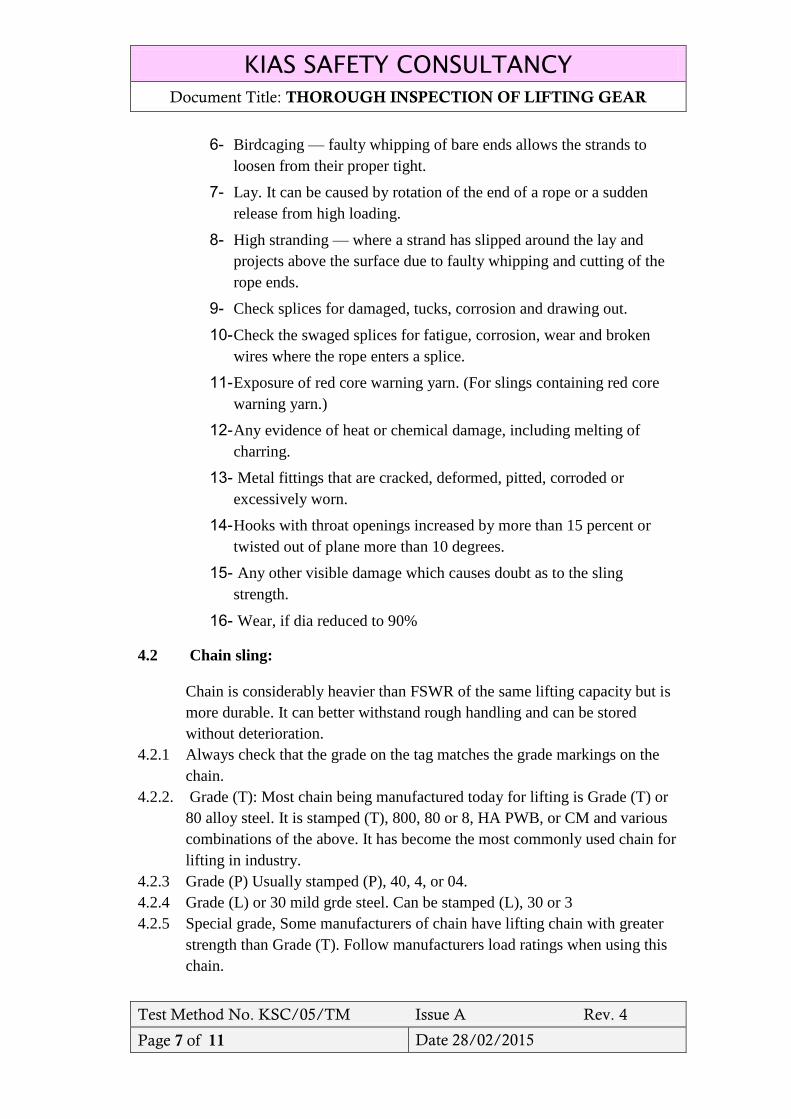
4.2.8 Inspect each link for signs of wear, twisting, stretching, nicks or gouging.
(Links that are frozen together show that the chain has been stretched.)
4.2.9 Find cracks by dusting chain with fine powder. Dust any link that is suspect
and then blow the loose particles away. Dust particles will lodge in any
cracks making them more visible.
4.2.10 Measure all worn links for the degree of wear. Wear must not exceed that
allowed for by the manufacture,
a) The maximum allowable chain wear is 10 per cent.
b) The maximum allowable elongation of a chain is 10 per cent.
c) The maximum increase in hook opening is 5 per cent of the original throat
opening.
d) The maximum allowable wear in the bite of a hook is 10 per cent.
4.2.11 Inspect upper and lower terminal links and hooks for signs of wear at their
load-bearing points and for any signs of distortion.
4.2.12 Inspect links and fittings for signs of wear at their load bearing points and
for excessive play in the load pin between the body halves.
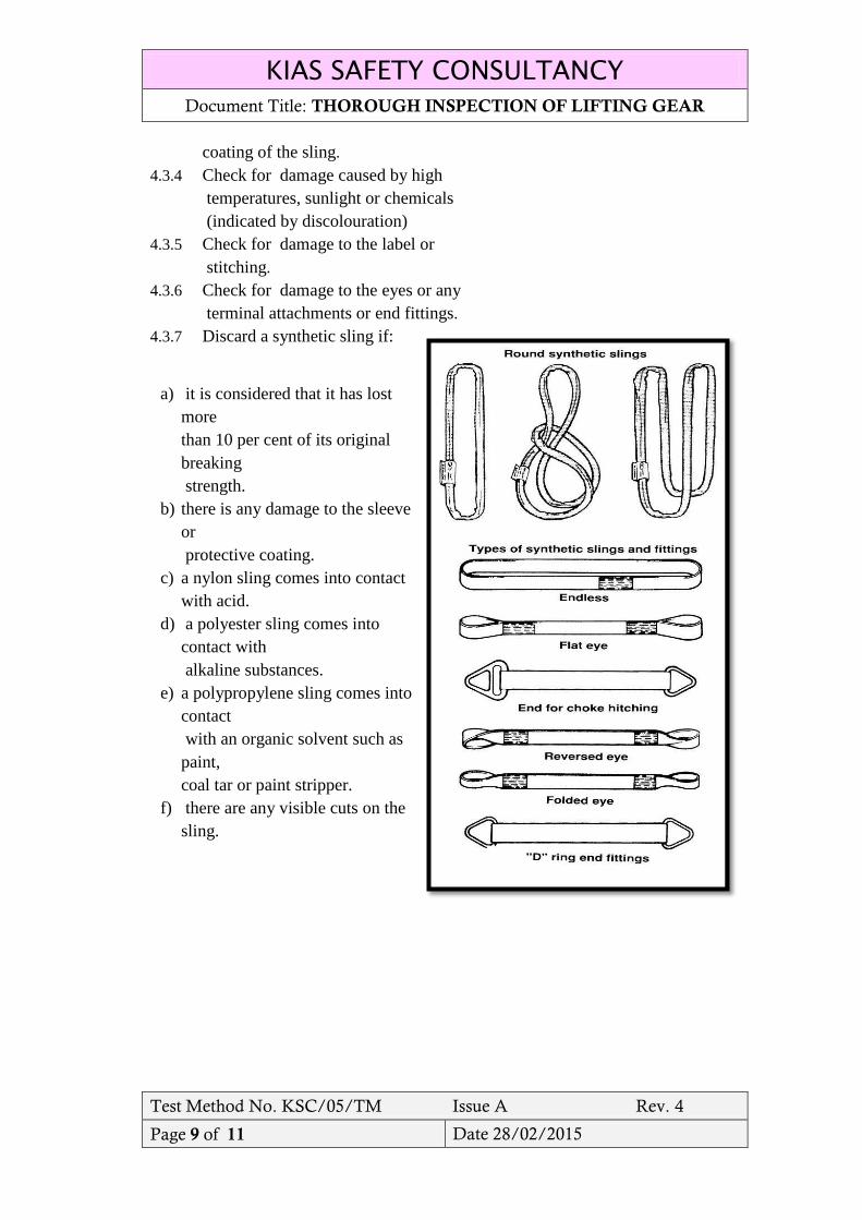
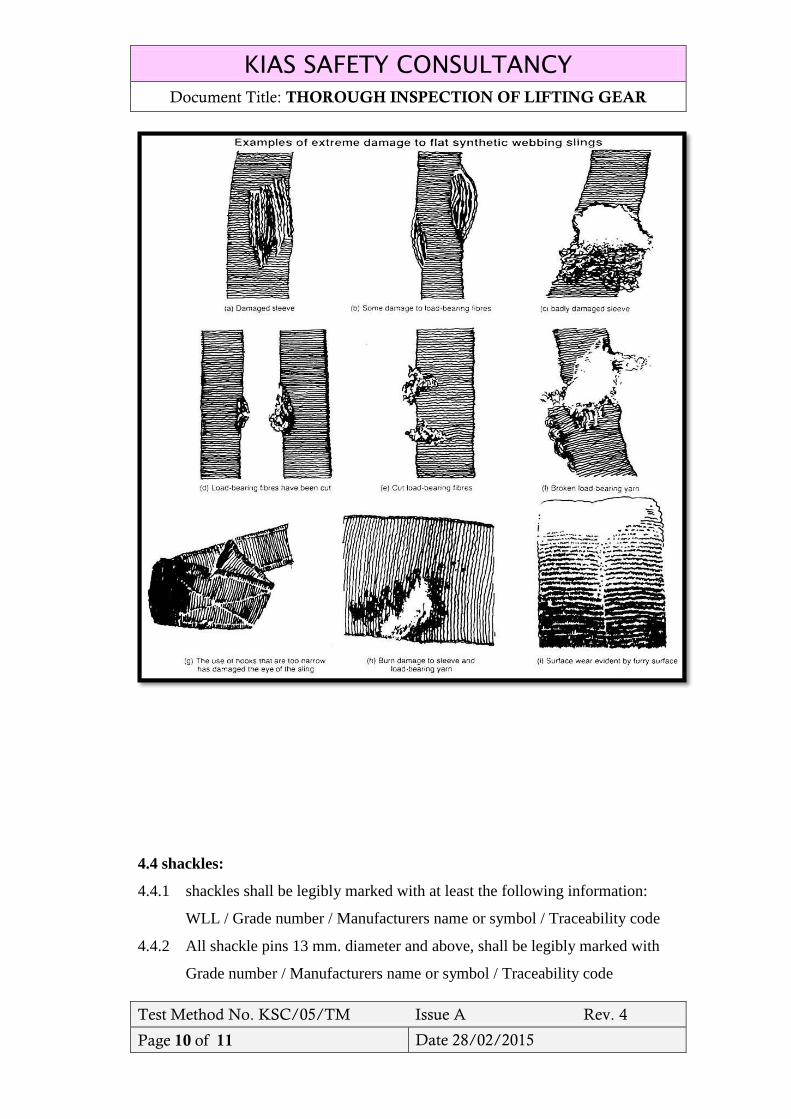
4.3 Flat webbing and round synthetic slings:
4.3.1 check for any external wear such as abrasions or cuts and contusions.
4.3.2 Check for internal wear which is often indicated by a thickening of the sling
or the presence of grit and dirt.
4.3.3 Check for damage to the protective
KIAS SAFETY CONSULTANCY
Document Title: THOROUGH INSPECTION OF LIFTING GEAR
Test Method No. KSC/05/TM Issue A Rev. 4
Page 9 of 11 Date 28/02/2015
coating of the sling.
4.3.4 Check for damage caused by high
temperatures, sunlight or chemicals
(indicated by discolouration)
4.3.5 Check for damage to the label or
stitching.
4.3.6 Check for damage to the eyes or any
terminal attachments or end fittings.
4.3.7 Discard a synthetic sling if:
a) it is considered that it has lost
more
than 10 per cent of its original
breaking
strength.
b) there is any damage to the sleeve
or
protective coating.
c) a nylon sling comes into contact
with acid.
d) a polyester sling comes into
contact with
alkaline substances.
e) a polypropylene sling comes into
contact
with an organic solvent such as
paint,
coal tar or paint stripper.
f) there are any visible cuts on the
sling.
KIAS SAFETY CONSULTANCY
Document Title: THOROUGH INSPECTION OF LIFTING GEAR
Test Method No. KSC/05/TM Issue A Rev. 4
Page 10 of 11 Date 28/02/2015
4.4 shackles:
4.4.1 shackles shall be legibly marked with at least the following information:
WLL / Grade number / Manufacturers name or symbol / Traceability code
4.4.2 All shackle pins 13 mm. diameter and above, shall be legibly marked with
Grade number / Manufacturers name or symbol / Traceability code
KIAS SAFETY CONSULTANCY
Document Title: THOROUGH INSPECTION OF LIFTING GEAR
Test Method No. KSC/05/TM Issue A Rev. 4
Page 11 of 11 Date 28/02/2015
4.4.3 Inspection should take place at least every six months and even more
frequently when the shackles are used in severe operating conditions.
4.4.4 examine Shackles to ensure that:
a) the body and pin are both identifiable as being of the same size, type and
make.
b) the threads of the pin and the body are undamaged;
c) verify that the safety bolt type shackle have the split cotter pin;
d) the body and the pin are not distorted, bent or twisted.
e) Examine the body and pin to be free from nicks, gouges, cracks, corrosion
and other defects by visual means and/or suitable crack detection
processes.
f) heat treated shackle shall be rejected as this may affect their Working Load
Limit;
g) Incorrect seating of the pin may be due to a bent pin, too tight fitting
thread or misalignment of the pin holes. Reject the shackle.
h) Examine shackle for excessive wear, wear reduction of greater than 10%
in the diameter of the bow or pin shall be rejected
5. RELATED FORMS
QSP09–D–01
QSP09–D–16
QSP09–D–24
QSP09–D–26
QSP09–D–27
QSP09–D–28
QSP09–D–29
QSP09–D–30