
04525908.pdf
5
Abstract —We propose an incremental frequency reuse (IFR) scheme that reuses effectively the radio spectrum through sys- tematic segment allocation over a cluster of adjoining cells. It divides the entire frequency spectrum into several spectrum segments. Based on the above segmentation, a set of cell- spe- cific segment allocation sequences is designed for universal frequency reuse. Here, each sequence defines its own base seg- ment and allocation order. The designed sequences are then assigned to respective cells over the cell cluster. In this scheme, the base segments over the cell cluster are mutually non-overlapped and collectively exhausted, and the added segments are interfered with from surrounding cells, but only in an incremental and coordinated manner. Hence, the proposed scheme can provide better reuse efficiency over the conven- tional ones such as the classical universal frequency reuse scheme and the soft frequency reuse (SFR) scheme. In addition, the simple and flexible IFR scheme can be easily configured as most existing reuse schemes only by redefining the set of seg- ment allocation sequences. A system-level simulator for an orthogonal frequency division multiple access (OFDMA) cellu- lar system covering surrounding cells up to 3 rd -tier has been implemented. Simulation results show that the IFR scheme provides quite better reuse efficiency as compared to the clas- sical universal reuse scheme and the SFR scheme, especially at the cell-edge region. Keywords —Cellular System, Frequency Reuse, Incremental Frequency Reuse, OFDMA I. INTRODUCTION Over last two decades, there has been an upsurge of de- mands for mobile and wireless communications from several points of view such as new services and the number of sub- scribers [1]-[2]. In addition, next-generation mobile com- munication systems should be able to meet high-quality ser- vice requirements such as high-quality video and high-speed Internet over wireless networks at the lowest possible price. In particular, tremendous interests in multimedi a services are fueling the need for very high data rates in future wireless networks [1]. However, a radio spectrum might be lacking for supporting these demanding services unless an ep- och-making improvement in spectrum utilization has been done [1]-[2]. So far, several advanced mechanisms have been developed for better use of a radio spectrum. They include adaptive modulation and coding [3]-[4], hybrid automatic repeat re- quest [5], fast channel-aware scheduling [6]-[7], and multi- ple-input multiple-ou tput techniques [8]. Despite those ef- forts, there are still a lot of limiting factors to the system capacity in wireless cellular systems. In particular, inter-cell interference (ICI) from neighboring cells is one of major limiting factors to the achievable signal-to-interference-plus- noise ratio (SINR) and the system capacity, especially at the cell-edge region. In classical cellular systems, frequency reuse mechanisms have been adopted in order to avoid ICI from neighboring cells [9]. Such mechanisms limit the utilization of the avail- able frequency spectrum, of which amount is determined by the frequency reuse factor (FRF) adopted. Hence, the FRF of one or near one is getting one of most desirable features for upcoming systems. However, the classical universal fre- quency reuse scheme suffers from s evere ICI from adjoining cells [9]-[10] because of its tight frequency reuse. Recently, some promising flexible spectrum reuse schemes [10]-[13] have been proposed such as the SFR scheme adopted in the 3GPP-LTE system [10], [12] and the fractional frequency reuse (FFR) scheme [13]. Among them, the SFR scheme achieving FRF-one can overcome severe ICI from adjoining cells at a cell-edge region, by emphasizing a part (called as the primary band) of the available radio spec- trum and allocating it preferentially for cell-edge users. However, it still may incur even severer ICI to some of cell-edge users, because the high-powered primary band can accommodate only a pre-defined number of cell-edge users, while the remaining cell-edge users may be allocated to lim- itedly -powered secondary bands. In this paper, we propose an IFR scheme that reuses ef- fectively the radio spectrum by allocating systematically spectrum segments over a cluster of adjoining cells. It divides the entire frequency spectrum into several segments. A set of cell-specific segment allocation sequences is designed for universal frequency reuse. Here, each sequence defines its base segment and allocation order for additional segments. The designed sequences are assigned to respective cells over the cluster. In this scheme, all the base segments within the cell cluster are mutually non-overlapping and collectively exhausted, and the added segments are interfered with from surrounding cells, but only in an incremental and coordinated manner. In each cell, the base segment is occupied first, and then the remainder of traffic channels is allocated over the added segments. Hence, the IFR scheme can provide better reuse efficiency over the conventional ones. To verify the effectiveness of the proposed scheme, a system-level simu- lator for an OFDMA cellular system covering surrounding cells up to 3 rd -tier is implemented. We use the outage prob- ability, spectral efficiency, and overall cell capacity as per- formance measures. II. SYSTEM MODEL A. Spectrum Reuse and Inter-cell Interference In this subsection, we deal with a spectrum reuse strategy and an ICI model for a generic cellular system. Fig. 1(a) and (b) show frequency assignments and inter- fering cells or interfering sectors up to 3 rd -tier in a cellular system with FRF=3, for omni-cell and 3-sector cell, respec- Ki Tae Kim O and Seong Keun Oh School of Electrical and Computer Engineering Ajou University San 5, Wonchon-Dong, Youngtong-Gu, Suwon, 443-749, KOREA E-mails: {erene46 O , oskn}@ajou.ac. kr An Incremental Frequency Reuse Scheme for an OFDMA Cellular Sys- tem and Its Performance 978-1-4244-1645-5/08/$25.00 ©2008 IEEE 1504
Transcript of 04525908.pdf

Abstract —We propose an incremental frequency reuse (IFR)
scheme that reuses effectively the radio spectrum through sys-
tematic segment allocation over a cluster of adjoining cells. It
divides the entire frequency spectrum into several spectrum
segments. Based on the above segmentation, a set of cell- spe-
cific segment allocation sequences is designed for universal
frequency reuse. Here, each sequence defines its own base seg-
ment and allocation order. The designed sequences are then
assigned to respective cells over the cell cluster. In this scheme,
the base segments over the cell cluster are mutually
non-overlapped and collectively exhausted, and the added
segments are interfered with from surrounding cells, but only in
an incremental and coordinated manner. Hence, the proposed
scheme can provide better reuse efficiency over the conven-
tional ones such as the classical universal frequency reuse
scheme and the soft frequency reuse (SFR) scheme. In addition,
the simple and flexible IFR scheme can be easily configured as
most existing reuse schemes only by redefining the set of seg-
ment allocation sequences. A system-level simulator for an
orthogonal frequency division multiple access (OFDMA) cellu-
lar system covering surrounding cells up to 3rd-tier has been
implemented. Simulation results show that the IFR scheme
provides quite better reuse efficiency as compared to the clas-
sical universal reuse scheme and the SFR scheme, especially at
the cell-edge region.
Keywords —Cellular System, Frequency Reuse, Incremental
Frequency Reuse, OFDMA
I. INTRODUCTION
Over last two decades, there has been an upsurge of de-
mands for mobile and wireless communications from several
points of view such as new services and the number of sub-
scribers [1]-[2]. In addition, next-generation mobile com-
munication systems should be able to meet high-quality ser-
vice requirements such as high-quality video and high-speed
Internet over wireless networks at the lowest possible price.
In particular, tremendous interests in multimedia services are
fueling the need for very high data rates in future wireless
networks [1]. However, a radio spectrum might be lacking for
supporting these demanding services unless an ep-
och-making improvement in spectrum utilization has been
done [1]-[2].
So far, several advanced mechanisms have been developed
for better use of a radio spectrum. They include adaptive
modulation and coding [3]-[4], hybrid automatic repeat re-
quest [5], fast channel-aware scheduling [6]-[7], and multi-
ple-input multiple-output techniques [8]. Despite those ef-
forts, there are still a lot of limiting factors to the system
capacity in wireless cellular systems. In particular, inter-cell
interference (ICI) from neighboring cells is one of major
limiting factors to the achievable signal-to-interference-plus-
noise ratio (SINR) and the system capacity, especially at the
cell-edge region.
In classical cellular systems, frequency reuse mechanisms
have been adopted in order to avoid ICI from neighboring
cells [9]. Such mechanisms limit the utilization of the avail-
able frequency spectrum, of which amount is determined by
the frequency reuse factor (FRF) adopted. Hence, the FRF of
one or near one is getting one of most desirable features for
upcoming systems. However, the classical universal fre-
quency reuse scheme suffers from severe ICI from adjoining
cells [9]-[10] because of its tight frequency reuse.
Recently, some promising flexible spectrum reuse
schemes [10]-[13] have been proposed such as the SFR
scheme adopted in the 3GPP-LTE system [10], [12] and the
fractional frequency reuse (FFR) scheme [13]. Among them,
the SFR scheme achieving FRF-one can overcome severe ICI
from adjoining cells at a cell-edge region, by emphasizing a
part (called as the primary band) of the available radio spec-
trum and allocating it preferentially for cell-edge users.
However, it still may incur even severer ICI to some of
cell-edge users, because the high-powered primary band can
accommodate only a pre-defined number of cell-edge users,
while the remaining cell-edge users may be allocated to lim-
itedly -powered secondary bands.
In this paper, we propose an IFR scheme that reuses ef-
fectively the radio spectrum by allocating systematically
spectrum segments over a cluster of adjoining cells. It divides
the entire frequency spectrum into several segments. A set of
cell-specific segment allocation sequences is designed for
universal frequency reuse. Here, each sequence defines its
base segment and allocation order for additional segments.
The designed sequences are assigned to respective cells over
the cluster. In this scheme, all the base segments within the
cell cluster are mutually non-overlapping and collectively
exhausted, and the added segments are interfered with from
surrounding cells, but only in an incremental and coordinated
manner. In each cell, the base segment is occupied first, and
then the remainder of traffic channels is allocated over the
added segments. Hence, the IFR scheme can provide better
reuse efficiency over the conventional ones. To verify the
effectiveness of the proposed scheme, a system-level simu-
lator for an OFDMA cellular system covering surrounding
cells up to 3rd-tier is implemented. We use the outage prob-
ability, spectral efficiency, and overall cell capacity as per-
formance measures.
II. SYSTEM MODEL
A. Spectrum Reuse and Inter-cell Interference
In this subsection, we deal with a spectrum reuse strategy
and an ICI model for a generic cellular system.
Fig. 1(a) and (b) show frequency assignments and inter-
fering cells or interfering sectors up to 3rd-tier in a cellular
system with FRF=3, for omni-cell and 3-sector cell, respec-
Ki Tae Kim O and Seong Keun Oh
School of Electrical and Computer Engineering
Ajou UniversitySan 5, Wonchon-Dong, Youngtong-Gu, Suwon, 443-749, KOREA
E-mails: {erene46O, oskn}@ajou.ac.kr
An Incremental Frequency Reuse Scheme for an OFDMA Cellular Sys-tem and Its Performance
978-1-4244-1645-5/08/$25.00 ©2008 IEEE 1504
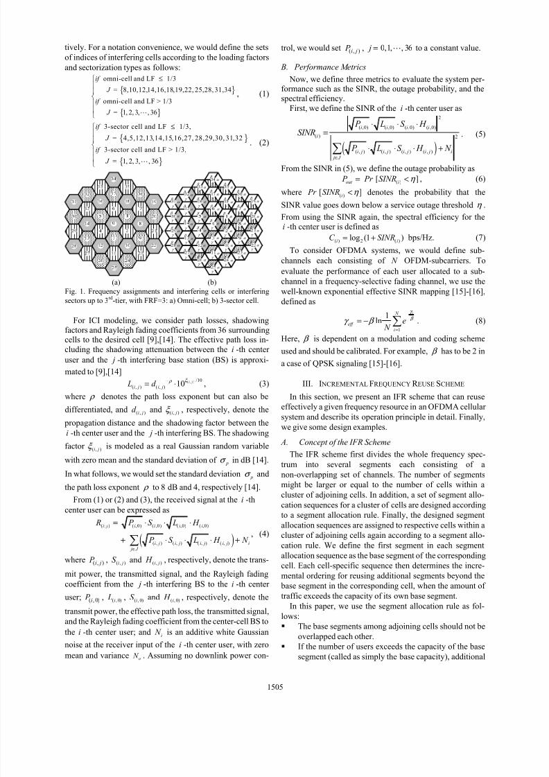
tively. For a notation convenience, we would define the sets
of indices of interfering cells according to the loading factors
and sectorization types as follows:
{ }
{ }
omni-cell and LF 1/3
= 8,10,12,14,16,18,19,22, 25,28, 31,34
omni-cell and LF > 1/3
= 1, 2, 3, , 36
if
J
if
J
≤
, (1)
{ }
{ }
3-sector cell and LF 1/3,
= 4,5,12,13,14,15,16,27, 28,29,30, 31,32
3-sector cell and LF > 1/3,
= 1, 2, 3, , 36
if
J
if
J
≤
. (2)
γ
β
α γ
β
α γ
β
α γ
β
α γ
β
α γ
β
α γ
β
α γ
β
α γ
β
α γ
β
α γ
β
α γ
β
α γ
β
α γ
β
α γ
β
α γ
β
α γ
β
α γ
β
α γ
β
α γ
β
α γ
β
α γ
β
α γ
β
α γ
β
α γ
β
α γ
β
α γ
β
α γ
β
α γ
β
α γ
β
α γ
β
α γ
β
α γ
β
α γ
β
α γ
β
α γ
β
α γ
β
α γ
β
(a) (b)
Fig. 1. Frequency assignments and interfering cells or interfering
sectors up to 3rd
-tier, with FRF=3: a) Omni-cell; b) 3-sector cell.
For ICI modeling, we consider path losses, shadowing
factors and Rayleigh fading coefficients from 36 surroundingcells to the desired cell [9],[14]. The effective path loss in-
cluding the shadowing attenuation between the i -th center
user and the j -th interfering base station (BS) is approxi-
mated to [9],[14]( , ) /10
( , ) ( , ) 10 i j
i j i j L d ξ ρ −
= ⋅ , (3)
where ρ denotes the path loss exponent but can also be
differentiated, and ( , )i jd and ( , )i jξ , respectively, denote the
propagation distance and the shadowing factor between the
i -th center user and the j -th interfering BS. The shadowing
factor ( , )i jξ is modeled as a real Gaussian random variable
with zero mean and the standard deviation of pσ in dB [14].
In what follows, we would set the standard deviation pσ and
the path loss exponent ρ to 8 dB and 4, respectively [14].
From (1) or (2) and (3), the received signal at the i -th
center user can be expressed as
( )
( : ) ( ,0) ( ,0) ( ,0) ( ,0)
( , ) ( , ) ( , ) ( , )
i j i i i i
i j i j i j i j i
j J
R P S L H
P S L H N ∈
= ⋅ ⋅ ⋅
+ ⋅ ⋅ ⋅ +∑, (4)
where ( , )i j P , ( , )i jS and ( , )i j H , respectively, denote the trans-
mit power, the transmitted signal, and the Rayleigh fading
coefficient from the j -th interfering BS to the i -th center
user; ( , 0)i P , ( , 0)i L , ( , 0)iS and ( , 0)i H , respectively, denote the
transmit power, the effective path loss, the transmitted signal,
and the Rayleigh fading coefficient from the center-cell BS to
the i -th center user; and i N is an additive white Gaussian
noise at the receiver input of the i -th center user, with zero
mean and variance o N . Assuming no downlink power con-
trol, we would set ( , )i j P , 0,1, , 36 j = to a constant value.
B. Performance Metrics
Now, we define three metrics to evaluate the system per-formance such as the SINR, the outage probability, and the
spectral efficiency.
First, we define the SINR of the i -th center user as
( )
2
( ,0) ( ,0) ( ,0) ( ,0)
( ) 2
( , ) ( , ) ( , ) ( , )
i i i i
i
i j i j i j i j i
j J
P L S H SINR
P L S H N ∈
⋅ ⋅ ⋅
=
⋅ ⋅ ⋅ +∑. (5)
From the SINR in (5), we define the outage probability as
( )[ ]out i P Pr SINR η = < , (6)
where ( )[ ]
i Pr SINR η < denotes the probability that the
SINR value goes down below a service outage threshold η .
From using the SINR again, the spectral efficiency for the
i -th center user is defined as
( ) 2 ( )log (1 )i iC SINR= + bps/Hz. (7)
To consider OFDMA systems, we would define sub-
channels each consisting of N OFDM-subcarriers. To
evaluate the performance of each user allocated to a sub-
channel in a frequency-selective fading channel, we use the
well-known exponential effective SINR mapping [15]-[16],
defined as
1
1ln
i N
eff
i
e N
γ
β γ β −
=
= − ∑ . (8)
Here, β is dependent on a modulation and coding scheme
used and should be calibrated. For example, β has to be 2 in
a case of QPSK signaling [15]-[16].
III. I NCREMENTAL FREQUENCY R EUSE SCHEME
In this section, we present an IFR scheme that can reuse
effectively a given frequency resource in an OFDMA cellular
system and describe its operation principle in detail. Finally,
we give some design examples.
A. Concept of the IFR Scheme
The IFR scheme first divides the whole frequency spec-
trum into several segments each consisting of a
non-overlapping set of channels. The number of segments
might be larger or equal to the number of cells within a
cluster of adjoining cells. In addition, a set of segment allo-
cation sequences for a cluster of cells are designed according
to a segment allocation rule. Finally, the designed segment
allocation sequences are assigned to respective cells within a
cluster of adjoining cells again according to a segment allo-
cation rule. We define the first segment in each segment
allocation sequence as the base segment of the corresponding
cell. Each cell-specific sequence then determines the incre-
mental ordering for reusing additional segments beyond the
base segment in the corresponding cell, when the amount of
traffic exceeds the capacity of its own base segment.
In this paper, we use the segment allocation rule as fol-
lows:
The base segments among adjoining cells should not be
overlapped each other.
If the number of users exceeds the capacity of the base
segment (called as simply the base capacity), additional
1505

segments assigned to a desired cell encroach partially or
fully base segments assigned to adjoining cells.
At every incremental stage to define the set of sequences,
each segment is assigned only once, but at least once
over the whole sequences.
A cluster consists of cells which use collectively the
complete set of segment allocation sequences.
B. Operation Principle
The details of operation principle are as follows:
1. In each cell within the cluster, the proposed scheme can
allocate arbitrarily channels within its own base segment
if the amount of traffic does not exceed the base capac-
ity.
2. Beyond the base capacity, it uses additional segments
according to the corresponding cell-specific segment
allocation sequence. It first completes channel alloca-
tion within its own base segment in the corresponding
cell and then allocates arbitrarily the remainder over the
newly added segments.
3. This process will be continued until all the segments are
exhausted, as the amount of traffic increases.
Using this principle, we can avoid major ICIs from ad-
joining cells when the amount of traffic is less than the base
capacity, while beyond the base capacity, ICI is averaged
over the newly added segments by arbitrary channel alloca-
tion. In addition, the IFR principle can be applied to both
omni-cell and 3-sector cell systems. The ICI control capa-
bility of the IFR scheme could be maximized if the
cell-specific subchannel allocation sequences designed ac-
cording to the above segment allocation rule are used within
the cluster of cells.
C. Design Examples
In our work, even if the IFR scheme can be widely applied
to cellular systems combined with various multiple access
technologies, we demonstrate its operation principle within
the viewpoint of an OFDMA cellular system, in which the
resource allocation is done on the basis of subchannel [17].
Now, we give two design examples as follows:
Scheme A for a cellular system based on FRF=3
Step 1. The scheme first divides the whole frequency spec-
trum into three segments each containing one-third
set of total non-overlapping subchannels, such as A-,
B-, and C -segments as shown Fig. 2.
Step 2. Below the loading factor of 1/3, the scheme allo-
cates arbitrarily subchannels only within only the
corresponding base segment for a desired cell to
demanding users.
Step 3. If the loading factor is greater than 1/3 and smaller
than 2/3, the scheme first completes the subchannel
allocation within the corresponding base segment
for the desired cell, and then allocates arbitrarily the
remainder of requested subchannels within the 2nd
segment (i.e., the 1st incremental segment) to de-
manding users.
Step 4. Finally, when the loading factor exceeds 2/3, the
scheme first completes the subchannel allocation
within the corresponding base segment and the 1st
incremental segment for the desired cell, and then
allocates arbitrarily the remainder of requested sub-
channels within the 3rd segment (i.e., the 2nd incre-
mental segment) for the desired cell to demanding
users.
Scheme B for a cellular system based on FRF=4
Step 1. The scheme first divides the whole frequency spec-
trum into four segments each containing one-fourth
set of total non-overlapping subchannels, such as A-,
B-, C-, and D -segments as shown Fig. 3.
Step 2. If the loading factor is greater than 1/4 and smaller
than 2/4, the scheme first completes the subchannel
allocation within the corresponding base segment
for the desired cell, and then allocates arbitrarily the
remainder of requested subchannels within the 2nd
segment to demanding users.
Step 3. This process will be continued until four segments
are exhausted.
0C
1C
2C
Power
Power
Power
Fig. 2. The concept of the proposed IFR scheme A in the omni-cell
environment for a cellular system based on FRF=3.
0C
1C
2C
Power
Power
Power
3C
Power
Fig. 3. The concept of the proposed IFR scheme B in the omni-cell
environment for a cellular system based on FRF=4.
Here, we would summarize the two sets of segment allo-
cation sequences as follows:
Using the scheme A
- Sequence-C0 : A-seg.→B-seg.→C-seg.,
- Sequence-C1 : B-seg.→C-seg.→A-seg.,
- Sequence-C2 : C-seg.→A-seg.→B-seg.
Using the scheme B
- Sequence-C0: A-seg.→B-seg.→C-seg.→D-seg.,
- Sequence-C1: B-seg.→C-seg.→D-seg.→A-seg.,
- Sequence-C2: C-seg.→D-seg.→A-seg.→B-seg.,
- Sequence-C3: D-seg.→A-seg.→B-seg.→C-seg.
IV. SIMULATION R ESULTS AND DISCUSSIONS
We performed computer simulations to demonstrate the
effectiveness of the proposed IFR scheme and also to com-
pare the proposed scheme with both the classical universal
frequency reuse scheme with FRF=1 [9] and the SFR scheme
[10], [12]. We used three performance measures such as the
1506
outage performance, spectral efficiency, and overall cell
capacity. We considered an OFDMA downlink cellular sys-
tem in an omni-cell case for simulations.
We assumed a uniform loading factor over all the cells
considered for the purpose of simplicity. We assumed a uni-
form user distribution within a hexagonal cell region. For all
simulations, we used simulation parameters as shown in
Table I. The cell-edge performance has been evaluated by
averaging over all the users between the radius of 0.9 km and
1.0 km. The overall cell capacity has been obtained by cu-
mulating the respective capacities of all the users within a cell,
uniformly distributed within the hexagonal cell region. Sub-
channel construction has been done based on the partial usage
of subcarriers (PUSC) channelization of the IEEE 802.16
standard, each consisting of 24 data subcarriers [18]. We
assumed that only one subchannel is allocated to each user
and the exponential effective SINR mapping [15]-[16] was
used.TABLE I
SIMULATION PARAMETERS
Parameter Value
No. of total subcarriers 2048
No. of data subcarriers 1680
No. of subchannels 60 No. of data subcarriers per sub-
channel24
No. of guard subcarriers Left(184), Right(183)
Path loss exponent 4Shadowing factor variance 8 dB
Spectral efficiency upper limit 4.5 bps/Hz
SINR outage threshold 3 dB
Maximum delay spread 81 n s
Cell radius 1 km (at a hexagonal vertex)
No. of interfering cells 36 (up to 3rd tier)
Power amplification factor α
(SFR scheme [10])1.5, 2
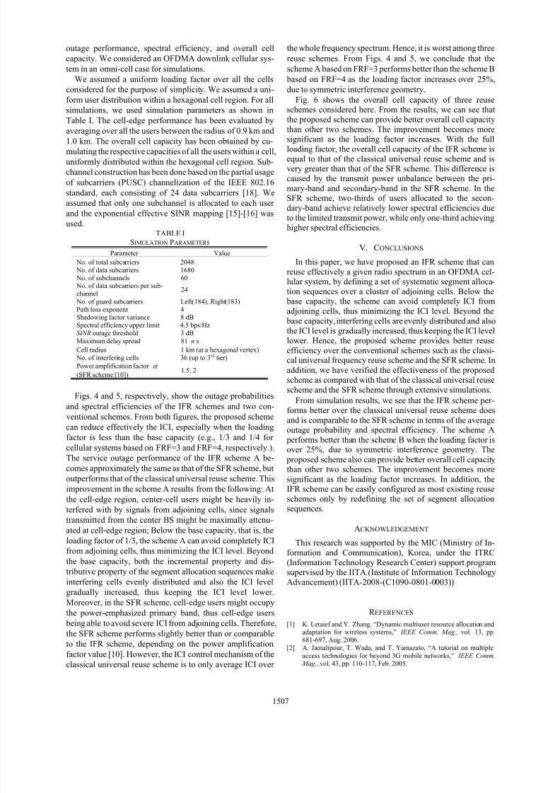
Figs. 4 and 5, respectively, show the outage probabilities
and spectral efficiencies of the IFR schemes and two con-
ventional schemes. From both figures, the proposed scheme
can reduce effectively the ICI, especially when the loading
factor is less than the base capacity (e.g., 1/3 and 1/4 for
cellular systems based on FRF=3 and FRF=4, respectively.).
The service outage performance of the IFR scheme A be-
comes approximately the same as that of the SFR scheme, but
outperforms that of the classical universal reuse scheme. This
improvement in the scheme A results from the following: At
the cell-edge region, center-cell users might be heavily in-
terfered with by signals from adjoining cells, since signals
transmitted from the center BS might be maximally attenu-
ated at cell-edge region; Below the base capacity, that is, the
loading factor of 1/3, the scheme A can avoid completely ICI
from adjoining cells, thus minimizing the ICI level. Beyond
the base capacity, both the incremental property and dis-
tributive property of the segment allocation sequences make
interfering cells evenly distributed and also the ICI level
gradually increased, thus keeping the ICI level lower.
Moreover, in the SFR scheme, cell-edge users might occupy
the power-emphasized primary band, thus cell-edge users
being able to avoid severe ICI from adjoining cells. Therefore,
the SFR scheme performs slightly better than or comparable
to the IFR scheme, depending on the power amplification
factor value [10]. However, the ICI control mechanism of the
classical universal reuse scheme is to only average ICI over
the whole frequency spectrum. Hence, it is worst among three
reuse schemes. From Figs. 4 and 5, we conclude that the
scheme A based on FRF=3 performs better than the scheme B
based on FRF=4 as the loading factor increases over 25%,
due to symmetric interference geometry.
Fig. 6 shows the overall cell capacity of three reuseschemes considered here. From the results, we can see that
the proposed scheme can provide better overall cell capacity
than other two schemes. The improvement becomes moresignificant as the loading factor increases. With the full
loading factor, the overall cell capacity of the IFR scheme is
equal to that of the classical universal reuse scheme and isvery greater than that of the SFR scheme. This difference is
caused by the transmit power unbalance between the pri-
mary-band and secondary-band in the SFR scheme. In theSFR scheme, two-thirds of users allocated to the secon-
dary-band achieve relatively lower spectral efficiencies due
to the limited transmit power, while only one-third achievinghigher spectral efficiencies.
V. CONCLUSIONS
In this paper, we have proposed an IFR scheme that can
reuse effectively a given radio spectrum in an OFDMA cel-lular system, by defining a set of systematic segment alloca-
tion sequences over a cluster of adjoining cells. Below the base capacity, the scheme can avoid completely ICI from
adjoining cells, thus minimizing the ICI level. Beyond the
base capacity, interfering cells are evenly distributed and also
the ICI level is gradually increased, thus keeping the ICI levellower. Hence, the proposed scheme provides better reuse
efficiency over the conventional schemes such as the classi-cal universal frequency reuse scheme and the SFR scheme. In
addition, we have verified the effectiveness of the proposed
scheme as compared with that of the classical universal reuse
scheme and the SFR scheme through extensive simulations.
From simulation results, we see that the IFR scheme per-
forms better over the classical universal reuse scheme does
and is comparable to the SFR scheme in terms of the averageoutage probability and spectral efficiency. The scheme A
performs better than the scheme B when the loading factor isover 25%, due to symmetric interference geometry. The
proposed scheme also can provide better overall cell capacity
than other two schemes. The improvement becomes more
significant as the loading factor increases. In addition, theIFR scheme can be easily configured as most existing reuse
schemes only by redefining the set of segment allocationsequences.
ACKNOWLEDGEMENT
This research was supported by the MIC (Ministry of In-
formation and Communication), Korea, under the ITRC
(Information Technology Research Center) support programsupervised by the IITA (Institute of Information Technology
Advancement) (IITA-2008-(C1090-0801-0003))
R EFERENCES
[1] K. Letaief and Y. Zhang, “Dynamic multiuser resource allocation andadaptation for wireless systems,” IEEE Comm. Mag., vol. 13, pp.
681-697, Aug. 2006.
[2] A. Jamalipour, T. Wada, and T. Yamazato, “A tutorial on multiple
access technologies for beyond 3G mobile networks,” IEEE Comm. Mag., vol. 43, pp. 110-117, Feb. 2005.
1507

[3] J. Hayes, “Adaptive feedback communications,” IEEE Trans. Comm.,
vol. 16, pp. 29-34, Feb. 1968.
[4] A. Goldsmith and S.-G. Chua, “Variable-rate variable-power MQAMfor fading channels,” IEEE Trans. Comm., vol. 45, pp. 1218-1230, Oct.
1997.
[5] R. A. Comore and D. J. Costello Jr., “ARQ schemes for data trans-
mission in mobile radio systems,” IEEE J. Select. Areas Comm., vol. 2, pp. 472-481, Jul. 1984.
[6] T. Kolding, “Link and system performance aspects of proportional fair
scheduling in WCDMA/HSDPA,” in Proc. IEEE VTC2003-Fall , vol. 3, pp. 1717-1722, Oct. 2003.
[7] M. C. Necker, “A comparison of scheduling mechanisms for service
class differentiation in HSDPA networks,” Int. J. Elect. Comm., vol. 60,
pp. 136-141, Feb. 2006.
[8] B. Vucetic and J. Yuan, Space-Time Coding , John Wiley, 2003.[9] T. S. Rappaport, Wireless Communications: Principles and Practice ,
Prentice Hall PTR, 2nd ed., 2002.
[10] Y. Xiang and J. Luo, “Inter-cell interference mitigation through flexi- ble resource reuse in OFDMA based communication networks,” in
Proc. European Wireless’2007 , pp. 1-7, Apr. 2007.
[11] M. Sternad, T. Ottosson, A. Ahl´en, and A. Svensson, “Attaining both
Coverageand High Spectral Efficiency with Adaptive OFDM
Downlinks,” in Proc. IEEE VTC2003-Fall , vol. 4, pp. 6-9,Oct. 2003.
[12] “Soft frequency reuse scheme for UTRAN LTE,” Huawei, 3GPPR1-050507, TSG RAN WG1 Meeting #41, Athens, Greece, May.
2005.
[13] J. Tomcik, Qualcomm, “MBFDD and MBTDD wideband mode,”
IEEE 802.20-05/68r1, Jan. 2006.[14] S. Plass, S. Sand, and G. Auer, “Modeling and analysis of a cellular
MC-CDMA downlink system,” in Proc. PIMRC2004, vol. 1, pp.
160-164, Sep. 2005.
[15] “Effective SIR computation for OFDM system-level simulations,”
Nortel, TSG-RAN WG1 #35, R03-1370, Nov. 2003.[16] R. Yaniv, D. Stopler, T. Kaitz, and K. Blum, ”CINR measurements
using the EESM method,” Alvarion Ltd., 2005[17] Z. Wang and R. A. Stiring-Gallacher, “Frequency reuse scheme for
cellular OFDM systems,” Electron. Lett., vol. 38, no. 8, pp. 387-388,
Apr. 2002.
[18] IEEE 802.16-2004, “IEEE standard for local and metropolitan areanetworks-Part 16: Air interface for fixed broadband wireless access
systems,” Oct. 1, 2004.
0.0 0.2 0.4 0.6 0.8 1.00.0
0.2
0.4
0.6
0.8
a v g .
o u
t a g e
p r o
b a
b i l i t y
loading factor
Cell-boundary (0.9-1km), SINRth=3dB
Classical(FRF=1)
IFR scheme
Scheme A(based on FRF=3)
Scheme B(based on FRF=4)
SFR scheme
(Primary-band : Secondary-band)
Power ratio 2:1 (α=1.5)
Power ratio 4:1 (α=2)
Fig. 4. Cell-edge average outage probability of three frequencyreuse schemes as a function of the loading factor, assuming uniform
loading factor over all the cells.
0.0 0.2 0.4 0.6 0.8 1.00
1
2
3
4
a v g .
s p e c
t r a l e
f f i c i e n c y
( b p s
/ H z
)
loading factor
Cell-boundary (0.9-1km), SINRth=3dB
Classical(FRF=1)
IFR scheme
Scheme A(based on FRF=3)
Scheme B(based on FRF=4)
SFR scheme
(Primary-band : Secondary-band)
Power ratio 2:1 (α=1.5)
Power ratio 4:1 (α=2)
Fig. 5. Cell-edge average spectral efficiency as a function of theloading factor in the same environment as in Fig. 4
0.0 0.2 0.4 0.6 0.8 1.00
20
40
60
80
100
120
o v e r a
l l c e
l l c a p a c
i t y ( b p s
/ H z
)
loading factor
SINRth=3dB
Classical(FRF=1)
IFR scheme
Scheme A(based on FRF=3)
Scheme B(based on FRF=4)
SFR scheme
(Primary-band : Secondary-band)
Power ratio 2:1 (α=1.5)
Power ratio 4:1 (α=2)
Fig. 6. Overall cell capacity as a function of the loading factor in the
same environment as in Fig. 4
1508


