
0443 394 101 GB - ESAB Welding & Cutting · Managing Director ESAB AB ... Equipment and its...
26
GB Valid for serial no. 035-xxx-xxxx 0443 394 101 GB 110301 A6 Slide Instruction manual
-
Upload
nguyendung -
Category
Documents
-
view
214 -
download
0
Transcript of 0443 394 101 GB - ESAB Welding & Cutting · Managing Director ESAB AB ... Equipment and its...

GB
Valid for serial no. 035-xxx-xxxx0443 394 101 GB 110301
A6
Slide
Instruction manual

DECLARATION OF CONFORMITYIn accordance with; the Machinery Directive 2006/42/EC
the EMC Directive 2004/108/EC
Type of equipment
Slide
Brand name or trade markESAB
Type designation etc.
A6 Slide with Electric motor, from Serial number 035 (2010 week 35)
The Slide is a building block in the ESAB A6 Welding Automation program
Manufacturer or his authorised representative established within the EEA
Name, address, telephone No, telefax No:
ESAB AB, Welding Equipment
Esabvägen, SE-695 81 LAXÅ, Sweden
Phone: +46 584 81 000, Fax: +46 584 411 924
The following harmonised standard in force within the EEA has been used in the design:EN 60204-1, Safety of machinery ć Electrical equipment of machines ć Party 1: General requirements
EN 12100-2, Safety of machinery ć Part 2: Technical principles
EN 60974-10, Arc welding equipment ć Part 10: Electromagnetic compatibility (EMC) requirements
By signing this document, the undersigned declares as manufacturer, or the manufacturer’s authorisedrepresentative established within the EEA, that the equipment in question complies with the safetyrequirements stated above.
DateLaxå 2011-02-04
Signature
Håkan FührManaging DirectorESAB AB
- 2 -

- 3 -TOCe
Rights reserved to alter specifications without notice.
1 SAFETY 4. . . . . . . . . . . . . . . . . . . . . . . . . . . . . . . . . . . . . . . . . . . . . . . . . . . . . . . . . . .
2 INTRODUCTION 6. . . . . . . . . . . . . . . . . . . . . . . . . . . . . . . . . . . . . . . . . . . . . . . . . . . 2.1 The A6 slide consists of: 6. . . . . . . . . . . . . . . . . . . . . . . . . . . . . . . . . . . . . . . . . . . . . . . . . . . .
3 TECHNICAL DATA 6. . . . . . . . . . . . . . . . . . . . . . . . . . . . . . . . . . . . . . . . . . . . . . . . .
4 TECHNICAL DESCRIPTION 7. . . . . . . . . . . . . . . . . . . . . . . . . . . . . . . . . . . . . . . . . 4.1 The carrying capacity of the slide 7. . . . . . . . . . . . . . . . . . . . . . . . . . . . . . . . . . . . . . . . . . . . 4.2 The linear bearing of the runner 8. . . . . . . . . . . . . . . . . . . . . . . . . . . . . . . . . . . . . . . . . . . . . 4.3 The distance between the fixation of the slide profile and the line of application of the load
104.4 Deformation of the slide profile under load 11. . . . . . . . . . . . . . . . . . . . . . . . . . . . . . . . . . . . 4.5 Slide transfer 14. . . . . . . . . . . . . . . . . . . . . . . . . . . . . . . . . . . . . . . . . . . . . . . . . . . . . . . . . . . . .
5 INSTALLATION 14. . . . . . . . . . . . . . . . . . . . . . . . . . . . . . . . . . . . . . . . . . . . . . . . . . . . 5.1 Connections of the runner 14. . . . . . . . . . . . . . . . . . . . . . . . . . . . . . . . . . . . . . . . . . . . . . . . . . 5.2 Connections of the slide profile 14. . . . . . . . . . . . . . . . . . . . . . . . . . . . . . . . . . . . . . . . . . . . . . 5.3 Fitting of vertical cross saddle 14. . . . . . . . . . . . . . . . . . . . . . . . . . . . . . . . . . . . . . . . . . . . . . . 5.4 Recommended way of lifting servo slides 15. . . . . . . . . . . . . . . . . . . . . . . . . . . . . . . . . . . . .
6 OPERATION 15. . . . . . . . . . . . . . . . . . . . . . . . . . . . . . . . . . . . . . . . . . . . . . . . . . . . . . . 6.1 Changing the speed range 15. . . . . . . . . . . . . . . . . . . . . . . . . . . . . . . . . . . . . . . . . . . . . . . . . .
7 MAINTENANCE 17. . . . . . . . . . . . . . . . . . . . . . . . . . . . . . . . . . . . . . . . . . . . . . . . . . . . 7.1 Daily: 17. . . . . . . . . . . . . . . . . . . . . . . . . . . . . . . . . . . . . . . . . . . . . . . . . . . . . . . . . . . . . . . . . . . . 7.2 Every month: 17. . . . . . . . . . . . . . . . . . . . . . . . . . . . . . . . . . . . . . . . . . . . . . . . . . . . . . . . . . . . . 7.3 Every year 17. . . . . . . . . . . . . . . . . . . . . . . . . . . . . . . . . . . . . . . . . . . . . . . . . . . . . . . . . . . . . . . . 7.4 As necessary 17. . . . . . . . . . . . . . . . . . . . . . . . . . . . . . . . . . . . . . . . . . . . . . . . . . . . . . . . . . . . . 7.5 In case of a long standstill 17. . . . . . . . . . . . . . . . . . . . . . . . . . . . . . . . . . . . . . . . . . . . . . . . . . 7.6 Changing linear bearings. 18. . . . . . . . . . . . . . . . . . . . . . . . . . . . . . . . . . . . . . . . . . . . . . . . . .
8 ORDERING OF SPARE PARTS 20. . . . . . . . . . . . . . . . . . . . . . . . . . . . . . . . . . . . . .
DIMENSION DRAWING 21. . . . . . . . . . . . . . . . . . . . . . . . . . . . . . . . . . . . . . . . . . . . . . . .
ORDERING NUMBER 22. . . . . . . . . . . . . . . . . . . . . . . . . . . . . . . . . . . . . . . . . . . . . . . . .
WEAR PARTS 23. . . . . . . . . . . . . . . . . . . . . . . . . . . . . . . . . . . . . . . . . . . . . . . . . . . . . . . .
ACCESSORIES 24. . . . . . . . . . . . . . . . . . . . . . . . . . . . . . . . . . . . . . . . . . . . . . . . . . . . . . .

- 4 -be03de
1 SAFETY
NOTE: The unit is tested by ESAB in a general set-up. The responsibility for safetyand function, of the specific set-up, lies with the integrator.
The following recommendations should be observed in addition to the standard regulations that applyto the work place.
All manoeuvres must be performed according to the given instructions by personnel well familiar withthe functions of the servo slide.
An incorrect manoeuvre, caused by a wrong move or an incorrect release of a functional sequence,can lead to an abnormal situation that can injure the operator and cause damage to the equipment.
1. Personnel working with the servo slide must be well familiar with:
� the handling of the slide
� the location of emergency stops
� the function of the slide
� all relevant safety regulations
2. Live electrical components are usually semi-protected.
� Any work on electrical units shall be carried out by a qualified electrician.
3. Danger of the load falling down
� Make sure the base will resist all types of forces coming up during operation.
� Check that the slide is fastened to the base with at least 4 M10 or M12 Allen screws.
� Never overload the slide (see on page 7 the carrying capacity of the slide)
� Check the condition of the belt regularly (at least every 200 hours).
� Replace the belt at least every 5 years, or as necessary.
N.B.When replacing the belt or the belt pulley the load must be secured. Read the page 16.
WARNING
In case of a belt rupture the load will fall down.
4. Danger of getting clamped
� When the runner goes towards its end position
� When the belt protection is dismounted
5. Maintenance
� Lubrication and maintenance of the slide must not be carried out when the slide is inoperation.
GB

- 5 -be03de
WARNING
Read and understand the instruction manual before installing or operating.
Arc welding and cutting can be injurious to yourself and others. Take precausions when welding andcutting. Ask for your employer's safety practices which should be based on manufacturers' hazarddata.
ELECTRIC SHOCK - Can kill� Install and earth the unit in accordance with applicable standards.� Do not touch live electrical parts or electrodes with bare skin, wet gloves or wet clothing.� Insulate yourself from earth and the workpiece.� Ensure your working stance is safe.
FUMES AND GASES - Can be dangerous to health� Keep your head out of the fumes.� Use ventilation, extraction at the arc, or both, to take fumes and gases away from your breathing zone
and the general area.
ARC RAYS - Can injure eyes and burn skin.� Protect your eyes and body. Use the correct welding screen and filter lens and wear protective
clothing.� Protect bystanders with suitable screens or curtains.
FIRE HAZARD� Sparks (spatter) can cause fire. Make sure therefore that there are no inflammable materials nearby.
NOISE - Excessive noise can damage hearing� Protect your ears. Use earmuffs or other hearing protection.� Warn bystanders of the risk.
MALFUNCTION - Call for expert assistance in the event of malfunction.
PROTECT YOURSELF AND OTHERS!
CAUTION
Class A equipment is not intended for use in residential locations wherethe electrical power is provided by the public low-voltage supply system.There may be potential difficulties in ensuring electromagneticcompatibility of class A equipment in those locations, due to conductedas well as radiated disturbances.
CAUTION
Read and understand the instruction manual beforeinstalling or operating.
Dispose of electronic equipment at the recycling facility!
In observance of European Directive 2002/96/EC on Waste Electrical and ElectronicEquipment and its implementation in accordance with national law, electrical and/orelectronic equipment that has reached the end of its life must be disposed of at arecycling facility.
As the person responsible for the equipment, it is your responsibility to obtaininformation on approved collection stations.
For further information contact the nearest ESAB dealer.
ESAB can provide you with all necessary welding protection and accessories.
GB
- 6 -be03de
2 INTRODUCTION
The A6 slide is designed to carry and transfer welding heads of different types ofwelding plants. The slide can be mounted across the weld joint − single or in a crosssaddle − for adjustment or joint tracking. It can also be mounted along the weld jointto bring about a welding movement.
The A6 slide is a motorized linear slide. All movable parts are lodged in ballbearings. The slide is available in different setting lengths from 60 to 1030 mm (seedimension drawing on page 21) and in two different speed ranges.
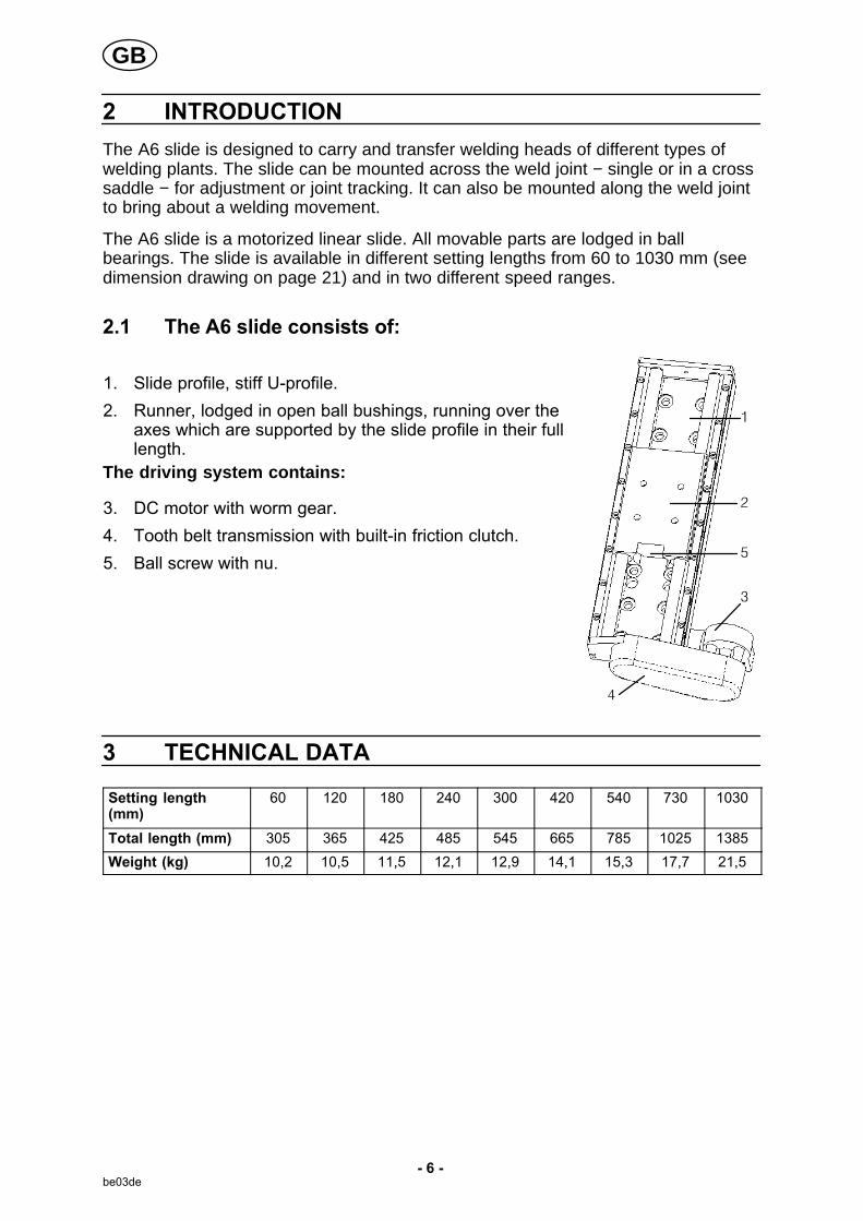
2.1 The A6 slide consists of:
1. Slide profile, stiff U-profile.
2. Runner, lodged in open ball bushings, running over theaxes which are supported by the slide profile in their fulllength.
The driving system contains:
3. DC motor with worm gear.
4. Tooth belt transmission with built-in friction clutch.
5. Ball screw with nu.
3 TECHNICAL DATA
Setting length(mm)
60 120 180 240 300 420 540 730 1030
Total length (mm) 305 365 425 485 545 665 785 1025 1385
Weight (kg) 10,2 10,5 11,5 12,1 12,9 14,1 15,3 17,7 21,5
GB

- 7 -be03de
A6 Slide
Max control voltage 42 V DC
Max speed at 42 V DC 70 cm/min (175 cm/min with reversed gearwheels in transmission)
Continuous A-weighted noise pressure 42 dB
Play of runner in the longitudinal direction ofthe slide
0,1 mm
Other play 0
Max ambient air temperature 80°CMax load dimensions at full setting length
Setting length 60 to 540: b=62
Setting length 60 to 730: b=86
Setting length 60 to 1030: b=117
4 TECHNICAL DESCRIPTION
4.1 The carrying capacity of the slide
To simplify the schematical representation it is assumed that the load on the slide isa weight and that the different mounting positions are confined to:
� Vertical position
� Standing horizontal position
� Lying horizontal position.
With the following co−ordinate directions the force of gravity works in the y, x and zdirections.
GB

- 8 -be03de
4.2 The linear bearing of the runner
Max permissible momemt−free load on the runner of the slide is 150 kg irrespectiveof the mounting position of the slide.
Max permissible moment−generating load on the runner of the slide depends on themounting position. The centre of gravity of the load can be displaced from the centreof the runner within an area, the further limit of which depends on the size of the loadaccording to the three diagrams below, where the slide is seen from above.
Max. load at vertical mounting Max load at standing horizontal mounting
Max load at lying horizontal mounting
GB

- 9 -be03de
Examplel 1:
� An A6 SFD1 automatic welding machine is mounted ona standing cross saddle.
� Note that the wire drum and the drum holder aremounted on th slide profile of the vertical slide.
Example 1a:
� The load on the vertical slide is about 43 kg.
� The centre of gravity (TP1) is displaced 0,35 mfrom the runner of the vertical slide in the zdirection.
� The displacement of the centre of gravity in the xdirection can be neglected.
� The load is far below the permissible load of 110kg in this position.
*1) Permissible position of the centre of gravity at aload of 40 kg.
*2) Permissible position of the centre of gravity at aload of 100 kg.
Example 2:
� A load of 50 kg is fitted on a lyinghorizontal slide.
� The centre of gravity is displaced 0,4m in the x direction.
� The centre of gravity can also bedisplaced 0,17 m in the y directionwithout the max load being exceeded.
*1) Permissible position of the centre ofgravity at a load of 50 kg.
GB

- 10 -be03de
4.3 The distance between the fixation of the slide profile and theline of application of the load
Max permissible forces on the mounting screws of the slide profile limits the distance(l) between the mounting screws and the application line of the load.
At standing horizontal mounting it is assumed that the tightening moment is 48 Nmfor an M10 screw and 84 Nm for an M12 screw (friction joint).
Max permissible distance; l as a function of the load F is shown in the followingdiagram where a is the distance between the screw pairs.
Example 3
� The horizontal slide in example 1 is to be fitted on a carrier with 2 pairs of screwswith a=60 mm.
� L is mmax 0,4 m.
� According to the diagram the actual weight of 100 kg (F=1000 N) requires thatthe mounting screws are of the M12 dimension and are tightened at 84 Nm.
*1) Standing horizontal mounting (SHM)
*2) Lying horizontal and vertical mounting (LHMand VM)
*3) Mounting screw
*4) 4 M12 screws torque moment 84 Nm
*5) 4 M10 screws torque moment 48 Nm
GB
- 11 -be03de
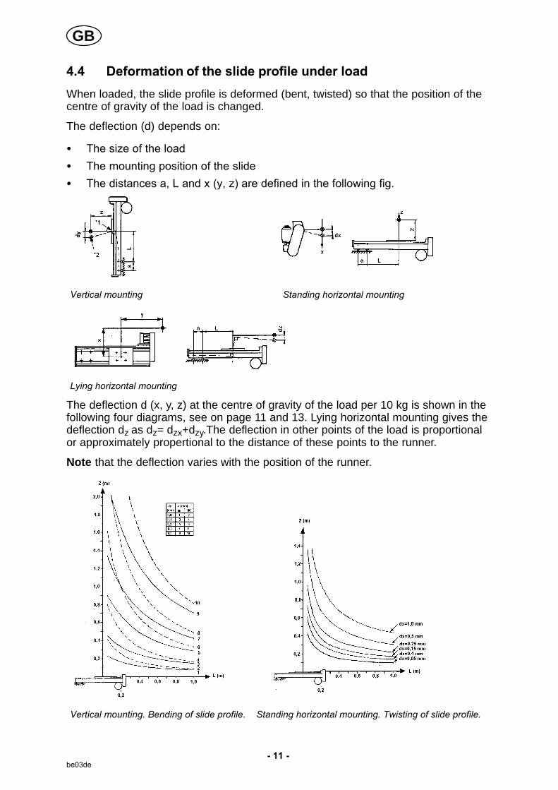
4.4 Deformation of the slide profile under load
When loaded, the slide profile is deformed (bent, twisted) so that the position of thecentre of gravity of the load is changed.
The deflection (d) depends on:
� The size of the load
� The mounting position of the slide
� The distances a, L and x (y, z) are defined in the following fig.
Vertical mounting Standing horizontal mounting
Lying horizontal mounting
The deflection d (x, y, z) at the centre of gravity of the load per 10 kg is shown in thefollowing four diagrams, see on page 11 and 13. Lying horizontal mounting gives thedeflection dz as dz= dzx+dzy.The deflection in other points of the load is proportionalor approximately propertional to the distance of these points to the runner.
Note that the deflection varies with the position of the runner.
Vertical mounting. Bending of slide profile. Standing horizontal mounting. Twisting of slide profile.
GB

- 12 -be03de
Example 4:
� An automatic welding machine is fitted on a verticalcross saddle.
� The load on the vertical slide is 43 kg.
� The position of the centre of gravity is at the distancez=0,35 m from the runner.
� The load on the horizontal slide is 100 kg and its centreof gravity is at the distance z=0,17 m from the runner.
Lmax of the vertical slide is 0,1 m and of the horizontal slide 0,4 m. The deflection ofthe contact device due to the deformation of the slide profiles of the slides can beestimated as follows:
1. Deflection due to deformation of the vertical slide:
� Insert L=0,1 m and z=0,35 into the left diagram, see on page 13 (thedistance to the centre of gravity TP1). In case a=60, use the solid curvelines.
� Then you will get a point that lies between curve 1 and curve 3 (closer tocurve 3).
� According to the table a=60 the deflection will be between 0,05 and 0,1 mm.It is estimated at 0,08 mm. This is the deflection in the centre of gravity TP1per 10 kg load.
� The deflection at 43 kg is: 0,08 x 43/10 = 0,34 mm
� The deflection of the contact device is then (due to proportinality): 0,34 x0,33/0,35 = 0,32 mm.
� 0,33 is the distance to the contact device
� 0,35 the distance to TP1.
2. Deflection due to deformation of the horizontal slide:
� Insert in L=0,4 m and z=0,17 m into the diagram on the right, see on page13 (the distance to the centre of gravity TP2).
� Then you will get a point indicating a deflection between 0,05 and 0,1 mm. Itis estimated at 0,07 mm. This is the deflection of the centre of gravity TP2per 10 kg load.
� The defection at 100 kg is: 0,07 x 100/10 = 0,7 mm
� The deflection of the contact device is then (due to proportionality): 0,07 x0,33/0,17 = 1,36 mm.
� 0,33 is the distance to the contact device
� 0,17 is the distance to TP2.
� The total deflection of the contact device is then at Lmax 1,36 + 0,32 = ca 1,7mm.
GB
- 13 -be03de
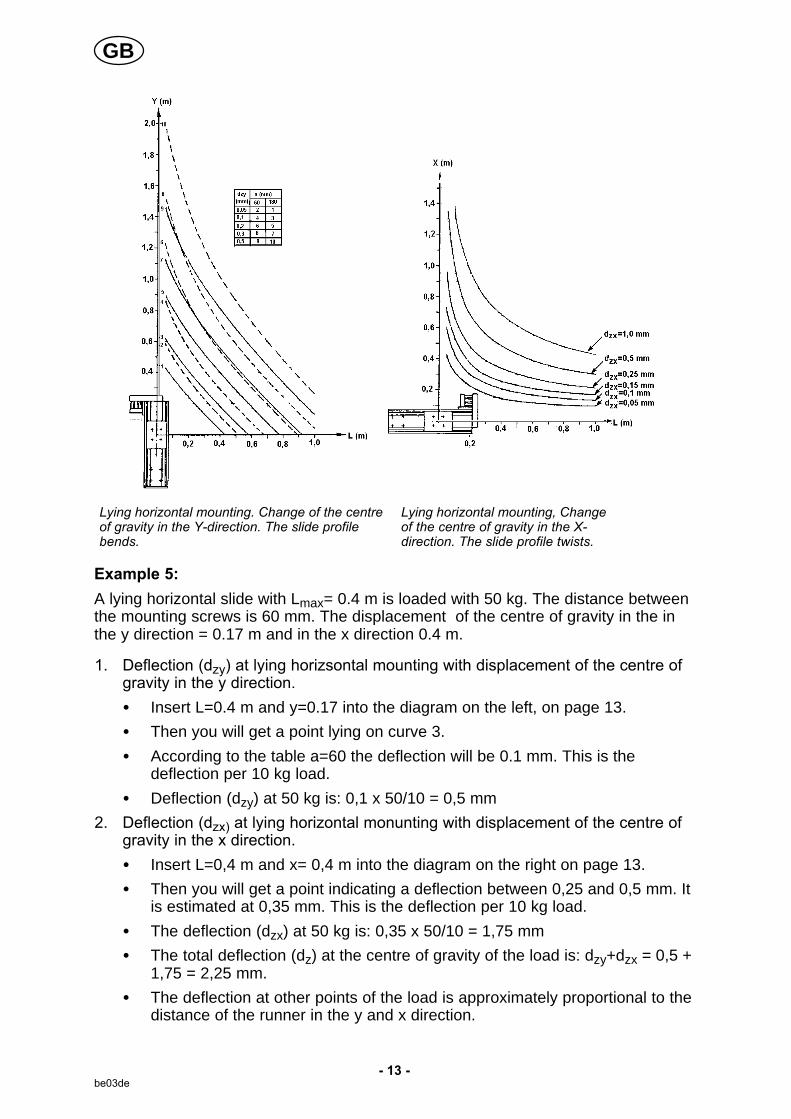
Lying horizontal mounting. Change of the centreof gravity in the Y-direction. The slide profilebends.
Lying horizontal mounting, Changeof the centre of gravity in the X-direction. The slide profile twists.
Example 5:
A lying horizontal slide with Lmax= 0.4 m is loaded with 50 kg. The distance betweenthe mounting screws is 60 mm. The displacement of the centre of gravity in the inthe y direction = 0.17 m and in the x direction 0.4 m.
1. Deflection (dzy) at lying horizsontal mounting with displacement of the centre ofgravity in the y direction.
� Insert L=0.4 m and y=0.17 into the diagram on the left, on page 13.
� Then you will get a point lying on curve 3.
� According to the table a=60 the deflection will be 0.1 mm. This is thedeflection per 10 kg load.
� Deflection (dzy) at 50 kg is: 0,1 x 50/10 = 0,5 mm
2. Deflection (dzx) at lying horizontal monunting with displacement of the centre ofgravity in the x direction.
� Insert L=0,4 m and x= 0,4 m into the diagram on the right on page 13.
� Then you will get a point indicating a deflection between 0,25 and 0,5 mm. Itis estimated at 0,35 mm. This is the deflection per 10 kg load.
� The deflection (dzx) at 50 kg is: 0,35 x 50/10 = 1,75 mm
� The total deflection (dz) at the centre of gravity of the load is: dzy+dzx = 0,5 +1,75 = 2,25 mm.
� The deflection at other points of the load is approximately proportional to thedistance of the runner in the y and x direction.
GB

- 14 -be03de
4.5 Slide transfer
Current consumption of electric motor and limit to self-braking
The current consumption is linearly depending on the load. In the table the currentconsumption is indicated for different gear ratios at idle running, full load and sliding .The table shows max load at self−braking of the motor worm gear.
Gear ratio for maxspeed (cm/min)
Total gear ratio,motor armature - sliderunner (r.p.m.)
Current consumption Max load at self-retarding (N)Idle
running
Load1500N
Sliding*1)
70 15,4 1,25 1,80 2,60 >1500
175 620 1,25 2,75 3,50 1000
*1) Adjustable, see on page 16.
5 INSTALLATION
The installation must be executed by a professional.
WARNING
Incorrect installation of the servo slide or incorrect fitting of the load on the slide can causedamage to the machine and injure people.
5.1 Connections of the runner
For the attachement of the load there are four M12 holes on the runner at a spacingof 60 mm for M12 screws or M10 Allen screws with washer.
5.2 Connections of the slide profile
For the attachement on a carrier there are holes ø 13 at a spacing of 60 mm for M12Allen screws or M10 Allen screws with washer.
Connect the slide to a suitable drive unit.
5.3 Fitting of vertical cross saddle
The vertical cross saddle can be mounted in severalways. For heavy loads the vertical slide is to be fittednext to the load to lessen the pressure on the backslide runner.
Recommended fitting for heavy loads: no torque onthe back slide runner.
The different mounting positions of the slide are:vertical position, standing horizontal and lyinghorizontal position.
*1. Load
GB

- 15 -be03de
Vertical mounting Standing horizontal mounting Lying horizontal mounting
5.4 Recommended way of lifting servo slides
The dead weight of most slides is so low that manual lifting can take place. Forslides with an adjustable length over 540 mm and for assembled cross saddles anapproved lifting device should be used.
NOTE. The runner must not be used for lifting.
Lifting points can be fitted in the holes on the slide profile. In exceptional cases a softlifting loop round the slide profile can be used. The loop must be properly secured soas to prevent slipping.
6 OPERATION
General safety regulations for the handling of the equipment can be found onpage 4. Read through before you start using the equipment!
WARNING
Rotating parts can cause injury, take great care.
6.1 Changing the speed range
WARNING
Falling load can cause damage.When replacing the belt or the belt pulley the load must be secured.
GB

- 16 -be03de
Replacing the belt pulley
Before starting the work, secure the load by running the slide/load to the bottomposition in order to prevent the load falling.
Max speed Wheel on motor shaft Wheel on ball screw Motor
70 cm/min 19 teeth 30 teeth, for slip coupling shaft journal, length 25 mm
175 cm/min 30 teeth, for slip coupling 19 teeth shaft journal, length 25 mm
110 cm/min 30 teeth, for slip coupling 30 teeth shaft journal, length 25 mm
When replacing the pulley, turn the cover plate between the motor and the motorbracket so that the mounting holes get covered.
NB. When mounting or dismounting the belt pulley with the slip coupling thelubricated cup springs must not get into contact with the friction surface of the pulley,friction ring or friction stop.
Adjusting the friction moment
� Tighten the centre screw 3/4 turn after the position where the cup springs startworking.
� The friction moment can be decreased as necessary (for instance to lessen thefriction current) by tightening the centre screw less than 3/4 turn.
NB. The friction moment must not be set higher as this can cause damage to theslide in the event of blocking.
Adjusting the tension of the belt
The belt must be replaced at least every 5 years,or as necessary.
� Make sure the load is secured whenperforming a piece of work.
� Dismount the belt protection.
� Loosen the motor. In case the pulley with the slip coupling is fitted on the motorshaft the belt drive must first be dismounted (in order that the mounting screwsof the motor become accessible), and then remounted again.
� Move the motor sideways until the belt is so tense that a force of 3,5 N appliedon the belt right between the pulleys gives a deflection of 2,5 mm.
� Tighten the mounting screws of the motor.
� When the pulley with the slip coupling is on the motor shaft, turn the pulley (slipcoupling loosened) until the notch in the edge comes just opposite the screwfitted between the belt sides. Tighten the screw.
� Dismount the belt pulleys to make it possible to tighten the other screws.
� Fit the belt drive and adjust the slip coupling.
� Put back the belt protection.
GB

- 17 -be03de
7 MAINTENANCE
Regular maintenance is important for safe, reliable operation.
CAUTION
All guarantee undertakings from the supplier cease to apply if the customer himselfattempts any work in the product during the guarantee period in order to rectify any faults.
7.1 Daily:
� Blow the slide clean from flux and dust.
7.2 Every month:
� Check the tooth belt and replace as necessary.
Note that the belt must be replaced at least every 5 years.
NOTE. This is a safety requirement at vertical mounting position as the load ofthe slide will fall down in case of a belt rupture.
When replacing the belt or the belt pulley the load must be secured. Read thepages 16 - 16.
7.3 Every year
� Make sure the slip coupling is adjusted to the right slipping torque. See thepages 16 - 16.
7.4 As necessary
� Lubricate the telescope bellows with molybdendisulfide.
Lubrication of the slip coupling.
� Lubricate the cup springs and the smallest inside diameter of the pulley usingmolybdendisulfide.
NB. The lubricant must not get into contact with the friction surfaces of thepulley, the friction ring or the friction stud.
Replace wear parts of the slip coupling.
� Replace the friction ring and/or the cup spring.
� Lubricate according to above recommendations.
Adjust the friction moment (see also Operation on page 16).
� Tighten the centre screw of the slip coupling 3/4 turn after the position where thecup springs start working.
7.5 In case of a long standstill
� Lubricate the unprotected surfaces of the steel shafts to avoid corrosion.
GB

- 18 -be03de
� NB. Molybdendisulfide must not be used.
� Anti-corrosives in spray packing is recommended to make it possible to reacheven hidden surfaces.
7.6 Changing linear bearings.
1 Belt pulley 5 Ball screw 8 End washer
2 Wedge 6 Runner 9 Slide profile
3 Ball bearing nut 7 Ball nut 10 Ball bushing
4 Steel shaft
The linear bearings of the slide consist of two steel shafts (4) and four ball bushings (10).
GB
- 19 -be03de
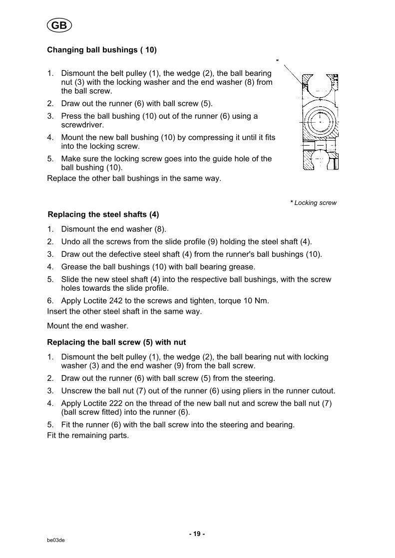
Changing ball bushings ( 10)
1. Dismount the belt pulley (1), the wedge (2), the ball bearingnut (3) with the locking washer and the end washer (8) fromthe ball screw.
2. Draw out the runner (6) with ball screw (5).
3. Press the ball bushing (10) out of the runner (6) using ascrewdriver.
4. Mount the new ball bushing (10) by compressing it until it fitsinto the locking screw.
5. Make sure the locking screw goes into the guide hole of theball bushing (10).
Replace the other ball bushings in the same way.
* Locking screw
Replacing the steel shafts (4)
1. Dismount the end washer (8).
2. Undo all the screws from the slide profile (9) holding the steel shaft (4).
3. Draw out the defective steel shaft (4) from the runner's ball bushings (10).
4. Grease the ball bushings (10) with ball bearing grease.
5. Slide the new steel shaft (4) into the respective ball bushings, with the screwholes towards the slide profile.
6. Apply Loctite 242 to the screws and tighten, torque 10 Nm.
Insert the other steel shaft in the same way.
Mount the end washer.
Replacing the ball screw (5) with nut
1. Dismount the belt pulley (1), the wedge (2), the ball bearing nut with lockingwasher (3) and the end washer (9) from the ball screw.
2. Draw out the runner (6) with ball screw (5) from the steering.
3. Unscrew the ball nut (7) out of the runner (6) using pliers in the runner cutout.
4. Apply Loctite 222 on the thread of the new ball nut and screw the ball nut (7)(ball screw fitted) into the runner (6).
5. Fit the runner (6) with the ball screw into the steering and bearing.
Fit the remaining parts.
GB

- 20 -be03de
8 ORDERING OF SPARE PARTS
Repair and electrical work should be performed by an authorized ESAB serviceman.Use only ESAB original spare and wear parts.
A6 Slide is designed and tested in accordance with the international and Europeanstandards EN 60204-1, EN 1050, EN 12100-2 and EN 60974-10. It is the obligation ofthe service unit which has carried out the service or repair work to make sure that theproduct still conforms to the said standard.
Spare parts may be ordered through your nearest ESAB dealer, see the last page ofthis publication.
GB
Edition 110301
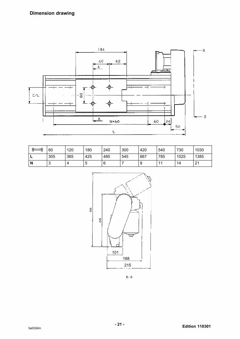
Dimension drawing
- 21 -be03dim
60 120 180 240 300 420 540 730 1030
L 305 365 425 485 545 667 785 1025 1385
N 3 4 5 6 7 9 11 14 21

Slide
Edition 110301
Ordering number
- 22 -be03o
Ordering no. Denomination Notes Max Speed
0334 333 880 A6 Slide Setting lenght = 60 mm 70cm/min
0334 333 881 A6 Slide Setting lenght = 120 mm 70cm/min
0334 333 882 A6 Slide Setting lenght = 180 mm 70cm/min
0334 333 883 A6 Slide Setting lenght = 240 mm 70cm/min
0334 333 884 A6 Slide Setting lenght = 300 mm 70cm/min
0334 333 885 A6 Slide Setting lenght = 420 mm 70cm/min
0334 333 886 A6 Slide Setting lenght = 540 mm 70cm/min
0334 333 887 A6 Slide Setting lenght = 730 mm 70cm/min
0334 333 888 A6 Slide Setting lenght = 1030 mm 70cm/min
0334 333 924 A6 Slide Setting lenght = 300 mm 330 cm/min
0334 333 940 A6 Slide Setting lenght = 60 mm *) 70cm/min
0334 333 941 A6 Slide Setting lenght = 120 mm *) 70cm/min
0334 333 942 A6 Slide Setting lenght = 180 mm *) 70cm/min
0334 333 943 A6 Slide Setting lenght = 240 mm *) 70cm/min
0334 333 944 A6 Slide Setting lenght = 300 mm *) 70cm/min
0334 333 945 A6 Slide Setting lenght = 420 mm *) 70cm/min
0334 333 946 A6 Slide Setting lenght = 540 mm *) 70cm/min
0459 839 055 Spare parts list
*) Optical pulse generator
The spare parts list is available on the Internet at www.esab.com
Slide
Edition 110301
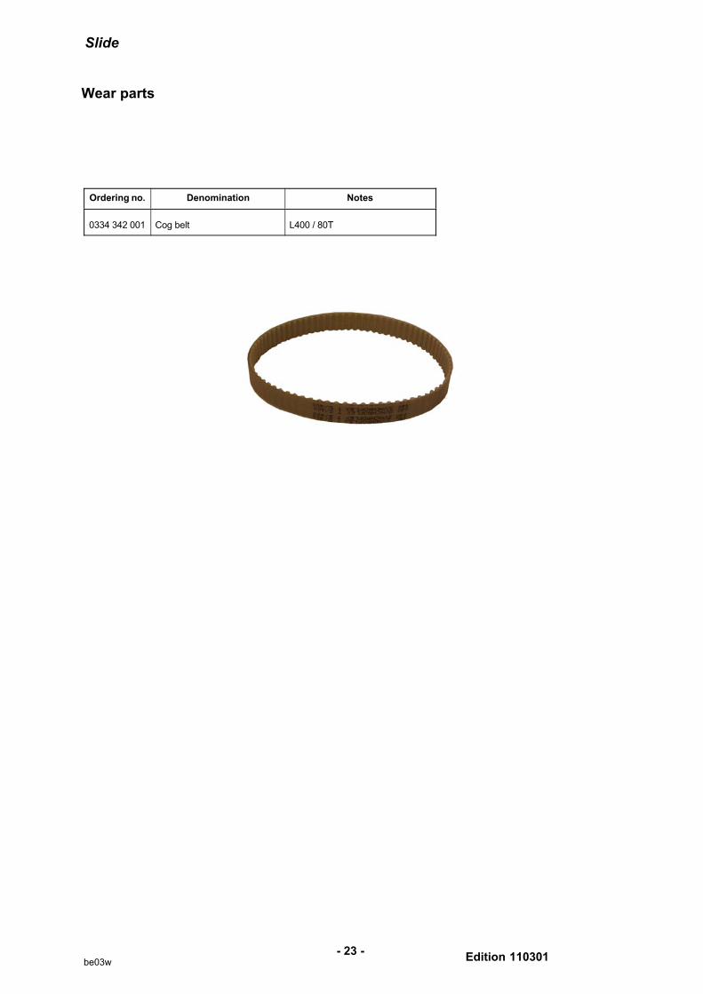
Wear parts
- 23 -be03w
Ordering no. Denomination Notes
0334 342 001 Cog belt L400 / 80T

Slide
Edition 110301
Accessories
- 24 -be03a
Motor cable, A6 Slide - Control box A6 GMH, A6 PAVand A6 FAA
2 m . . . . . . . . . . . . . . . . . . . . . . . . . . . . . . . . . . . . . .
5 m . . . . . . . . . . . . . . . . . . . . . . . . . . . . . . . . . . . . . .
10 m . . . . . . . . . . . . . . . . . . . . . . . . . . . . . . . . . . . . .
16 m . . . . . . . . . . . . . . . . . . . . . . . . . . . . . . . . . . . . .
19 m . . . . . . . . . . . . . . . . . . . . . . . . . . . . . . . . . . . . .
22 m . . . . . . . . . . . . . . . . . . . . . . . . . . . . . . . . . . . . .
25 m . . . . . . . . . . . . . . . . . . . . . . . . . . . . . . . . . . . . .
28 m . . . . . . . . . . . . . . . . . . . . . . . . . . . . . . . . . . . . .
32 m . . . . . . . . . . . . . . . . . . . . . . . . . . . . . . . . . . . . .
35 m . . . . . . . . . . . . . . . . . . . . . . . . . . . . . . . . . . . . .
0460 745 880
0460 745 881
0460 745 882
0460 745 883
0460 745 884
0460 745 885
0460 745 886
0460 745 887
0460 745 888
0460 745 889

- 25 -notes
NOTES
.............................................................................................................................................................
.............................................................................................................................................................
.............................................................................................................................................................
.............................................................................................................................................................
.............................................................................................................................................................
.............................................................................................................................................................
.............................................................................................................................................................
.............................................................................................................................................................
.............................................................................................................................................................
.............................................................................................................................................................
.............................................................................................................................................................
.............................................................................................................................................................
.............................................................................................................................................................
.............................................................................................................................................................
.............................................................................................................................................................
.............................................................................................................................................................
.............................................................................................................................................................
.............................................................................................................................................................
.............................................................................................................................................................
.............................................................................................................................................................
.............................................................................................................................................................
.............................................................................................................................................................
.............................................................................................................................................................
.............................................................................................................................................................
.............................................................................................................................................................
.............................................................................................................................................................
.............................................................................................................................................................
.............................................................................................................................................................
.............................................................................................................................................................
.............................................................................................................................................................
.............................................................................................................................................................
ESAB ABSE-695 81 LAXÅSWEDENPhone +46 584 81 000
www.esab.com
110210
ESAB subsidiaries and representative offices
EuropeAUSTRIAESAB Ges.m.b.H Vienna-Liesing Tel: +43 1 888 25 11 Fax: +43 1 888 25 11 85
BELGIUMS.A. ESAB N.V. Brussels Tel: +32 2 745 11 00 Fax: +32 2 745 11 28
BULGARIAESAB Kft Representative OfficeSofiaTel/Fax: +359 2 974 42 88
THE CZECH REPUBLICESAB VAMBERK s.r.o. VamberkTel: +420 2 819 40 885 Fax: +420 2 819 40 120
DENMARKAktieselskabet ESAB HerlevTel: +45 36 30 01 11 Fax: +45 36 30 40 03
FINLANDESAB Oy Helsinki Tel: +358 9 547 761 Fax: +358 9 547 77 71
FRANCEESAB France S.A. Cergy Pontoise Tel: +33 1 30 75 55 00 Fax: +33 1 30 75 55 24
GERMANYESAB GmbH Solingen Tel: +49 212 298 0 Fax: +49 212 298 218
GREAT BRITAINESAB Group (UK) Ltd Waltham Cross Tel: +44 1992 76 85 15 Fax: +44 1992 71 58 03
ESAB Automation Ltd Andover Tel: +44 1264 33 22 33 Fax: +44 1264 33 20 74
HUNGARYESAB Kft Budapest Tel: +36 1 20 44 182 Fax: +36 1 20 44 186
ITALYESAB Saldatura S.p.A. Bareggio (Mi) Tel: +39 02 97 96 8.1 Fax: +39 02 97 96 87 01
THE NETHERLANDSESAB Nederland B.V. Amersfoort Tel: +31 33 422 35 55Fax: +31 33 422 35 44
NORWAYAS ESAB Larvik Tel: +47 33 12 10 00 Fax: +47 33 11 52 03
POLANDESAB Sp.zo.o.Katowice Tel: +48 32 351 11 00Fax: +48 32 351 11 20
PORTUGALESAB Lda Lisbon Tel: +351 8 310 960Fax: +351 1 859 1277
ROMANIAESAB Romania Trading SRL BucharestTel: +40 316 900 600Fax: +40 316 900 601
RUSSIALLC ESABMoscowTel: +7 (495) 663 20 08 Fax: +7 (495) 663 20 09
SLOVAKIAESAB Slovakia s.r.o. Bratislava Tel: +421 7 44 88 24 26 Fax: +421 7 44 88 87 41
SPAINESAB Ibérica S.A. Alcalá de Henares (MADRID)Tel: +34 91 878 3600Fax: +34 91 802 3461
SWEDENESAB Sverige AB Gothenburg Tel: +46 31 50 95 00 Fax: +46 31 50 92 22
ESAB international AB Gothenburg Tel: +46 31 50 90 00 Fax: +46 31 50 93 60
SWITZERLANDESAB AG Dietikon Tel: +41 1 741 25 25 Fax: +41 1 740 30 55
UKRAINEESAB Ukraine LLCKievTel: +38 (044) 501 23 24Fax: +38 (044) 575 21 88
North and South AmericaARGENTINACONARCO Buenos Aires Tel: +54 11 4 753 4039 Fax: +54 11 4 753 6313
BRAZILESAB S.A. Contagem-MG Tel: +55 31 2191 4333 Fax: +55 31 2191 4440
CANADAESAB Group Canada Inc.Missisauga, Ontario Tel: +1 905 670 02 20 Fax: +1 905 670 48 79
MEXICOESAB Mexico S.A. Monterrey Tel: +52 8 350 5959 Fax: +52 8 350 7554
USAESAB Welding & Cutting Products Florence, SC Tel: +1 843 669 44 11 Fax: +1 843 664 57 48
Asia/PacificCHINAShanghai ESAB A/PShanghaiTel: +86 21 2326 3000Fax: +86 21 6566 6622
INDIAESAB India Ltd CalcuttaTel: +91 33 478 45 17 Fax: +91 33 468 18 80
INDONESIAP.T. ESABindo Pratama Jakarta Tel: +62 21 460 0188 Fax: +62 21 461 2929
JAPANESAB JapanTokyoTel: +81 45 670 7073Fax: +81 45 670 7001
MALAYSIAESAB (Malaysia) Snd Bhd USJTel: +603 8023 7835Fax: +603 8023 0225
SINGAPOREESAB Asia/Pacific Pte LtdSingapore Tel: +65 6861 43 22 Fax: +65 6861 31 95
SOUTH KOREAESAB SeAH Corporation Kyungnam Tel: +82 55 269 8170Fax: +82 55 289 8864
UNITED ARAB EMIRATESESAB Middle East FZEDubai Tel: +971 4 887 21 11Fax: +971 4 887 22 63
AfricaEGYPTESAB Egypt Dokki-CairoTel: +20 2 390 96 69 Fax: +20 2 393 32 13
SOUTH AFRICAESAB Africa Welding & Cutting LtdDurbanvill 7570 - Cape TownTel: +27 (0)21 975 8924
DistributorsFor addresses and phonenumbers to our distributors inother countries, please visit ourhome page
www.esab.com