03 Lubricating Oil System
28
1 © Wärtsilä 27 September 2007 W50DF03V00BTM01A Rev. 01 03. LUBRICATING OIL SYSTEM WÄRTSILÄ W50DF STANDARD ENGINE
description
wartsila
Transcript of 03 Lubricating Oil System

1 © Wärtsilä 27 September 2007 W50DF03V00BTM01A Rev. 01
03. LUBRICATING OIL SYSTEMWÄRTSILÄ W50DF
STANDARD ENGINE
2 © Wärtsilä 27 September 2007 W50DF03V00BTM01A Rev. 01
03 LUBRICATING OIL SYSTEM
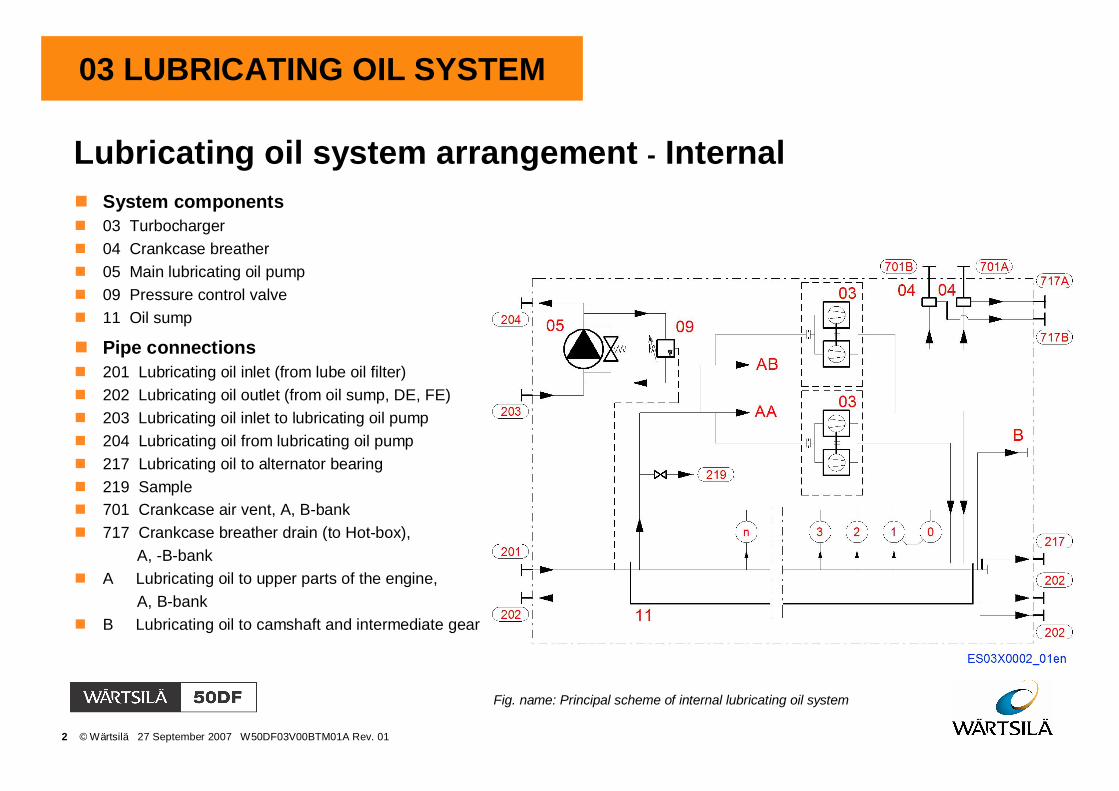
Lubricating oil system arrangement - InternalSystem components03 Turbocharger04 Crankcase breather05 Main lubricating oil pump09 Pressure control valve11 Oil sump
Pipe connections201 Lubricating oil inlet (from lube oil filter)202 Lubricating oil outlet (from oil sump, DE, FE)203 Lubricating oil inlet to lubricating oil pump204 Lubricating oil from lubricating oil pump217 Lubricating oil to alternator bearing219 Sample701 Crankcase air vent, A, B-bank717 Crankcase breather drain (to Hot-box),
A, -B-bankA Lubricating oil to upper parts of the engine,
A, B-bankB Lubricating oil to camshaft and intermediate gear
Fig. name: Principal scheme of internal lubricating oil system

3 © Wärtsilä 27 September 2007 W50DF03V00BTM01A Rev. 01
03 LUBRICATING OIL SYSTEM
Lubricating oil system on engine
System components01 Lubricating oil system at free end02 Lubricating oil storage system03 Lubricating oil delivery system04 Running-in filter (for commissioningand maintenance)
Fig. name: Lubricating oil system on engine
The arrangement on the engine consist oflubricating system at free end, storage system,delivery system, lubricating oil control devicesand oil condition monitoring systems.
4 © Wärtsilä 27 September 2007 W50DF03V00BTM01A Rev. 01
03 LUBRICATING OIL SYSTEM
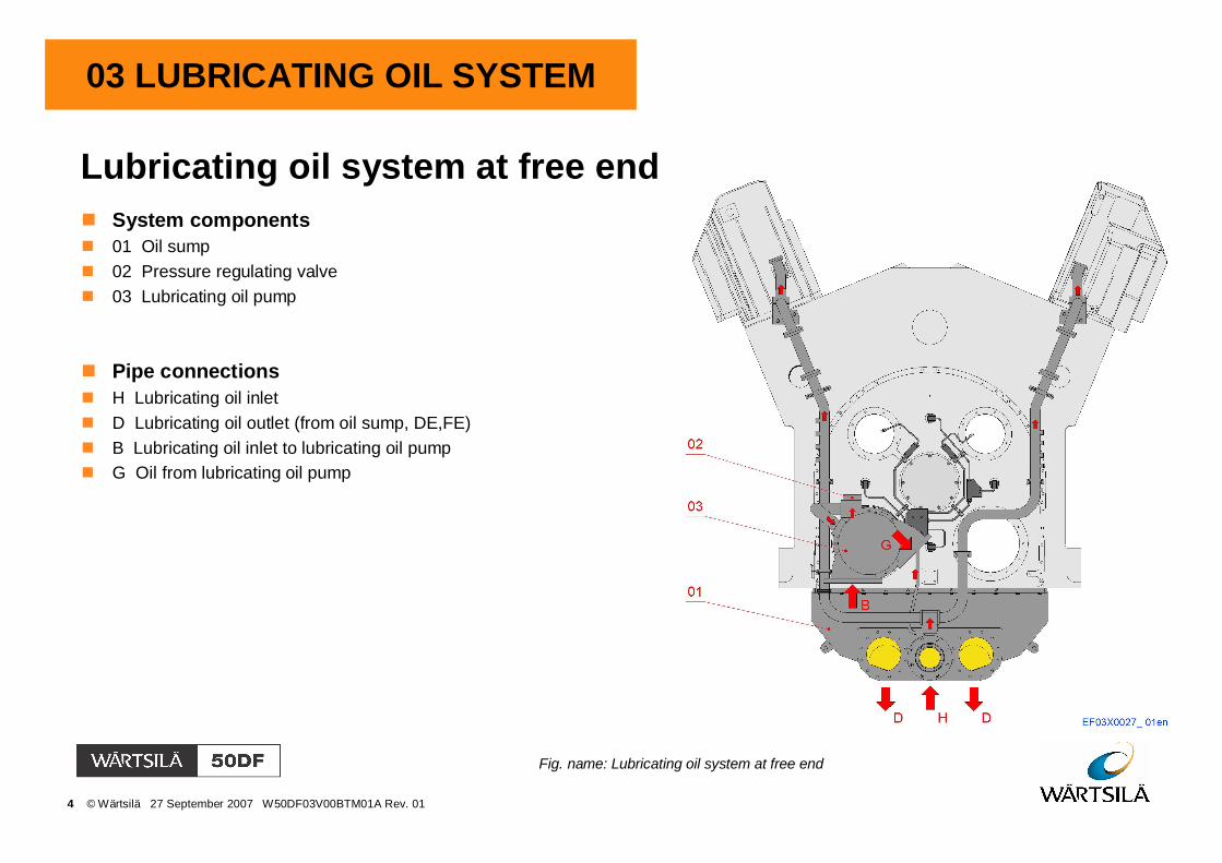
Lubricating oil system at free endSystem components01 Oil sump02 Pressure regulating valve03 Lubricating oil pump
Pipe connectionsH Lubricating oil inletD Lubricating oil outlet (from oil sump, DE,FE)B Lubricating oil inlet to lubricating oil pumpG Oil from lubricating oil pump
Fig. name: Lubricating oil system at free end
5 © Wärtsilä 27 September 2007 W50DF03V00BTM01A Rev. 01
03 LUBRICATING OIL SYSTEM
Lubricating oil sump
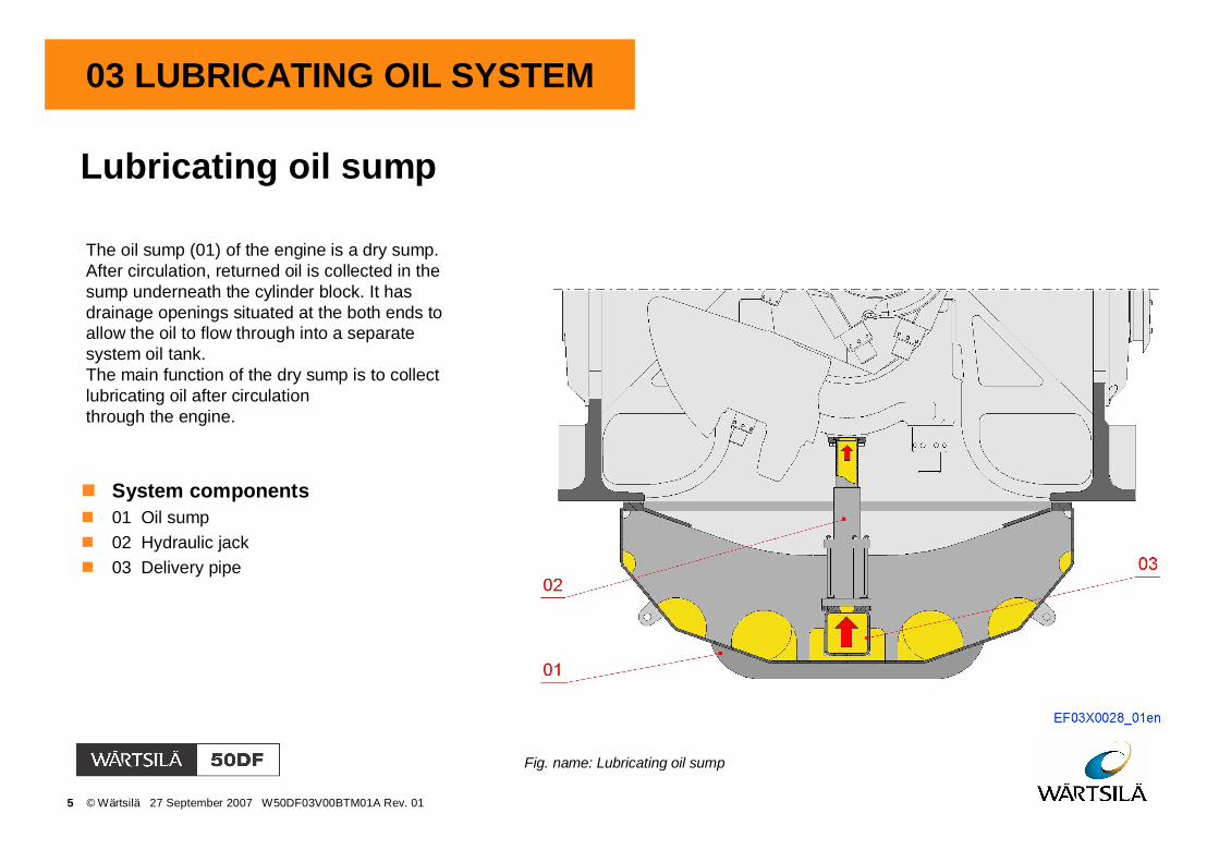
Fig. name: Lubricating oil sump
The oil sump (01) of the engine is a dry sump.After circulation, returned oil is collected in thesump underneath the cylinder block. It hasdrainage openings situated at the both ends toallow the oil to flow through into a separatesystem oil tank.The main function of the dry sump is to collectlubricating oil after circulationthrough the engine.
System components01 Oil sump02 Hydraulic jack03 Delivery pipe

6 © Wärtsilä 27 September 2007 W50DF03V00BTM01A Rev. 01
03 LUBRICATING OIL SYSTEM
Hydraulic jack
Fig. name: Hydraulic jack
ConnectionsA Pressure connection, when liftingB Pressure connection, when loweringC Lubricating oil inlet
Components01 Cylinder02 Oil pipe03 Piston04 Piston05 Piston06 Support ring07 O-ring

7 © Wärtsilä 27 September 2007 W50DF03V00BTM01A Rev. 01
03 LUBRICATING OIL SYSTEM
Lubricating oil delivery system
System components01 Oil inlet at free end02 Oil piping for main moving parts03 Oil piping at driving end04 Oil piping for turbocharger05 Oil piping for cylinder head06 Oil piping for injection pump, tappets andcamshaft bearings
Fig. name: Lubricating oil delivery system
Lubricating oil piping is made in seamless carbonsteel and seamless precision tubes in carbon orstainless steel. Lubricating delivery piping can bedivided into sub-systems as follows.

8 © Wärtsilä 27 September 2007 W50DF03V00BTM01A Rev. 01
03 LUBRICATING OIL SYSTEM
Splash guards at free end
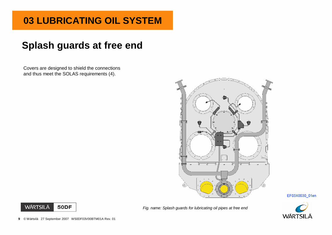
Fig. name: Splash guards for lubricating oil pipes at free end
Covers are designed to shield the connectionsand thus meet the SOLAS requirements (4).
9 © Wärtsilä 27 September 2007 W50DF03V00BTM01A Rev. 01
03 LUBRICATING OIL SYSTEM
Splash guards at free end
Fig. name: Splash guards for lubricating oil pipes at free end
Covers are designed to shield the connectionsand thus meet the SOLAS requirements (4).
10 © Wärtsilä 27 September 2007 W50DF03V00BTM01A Rev. 01
03 LUBRICATING OIL SYSTEM
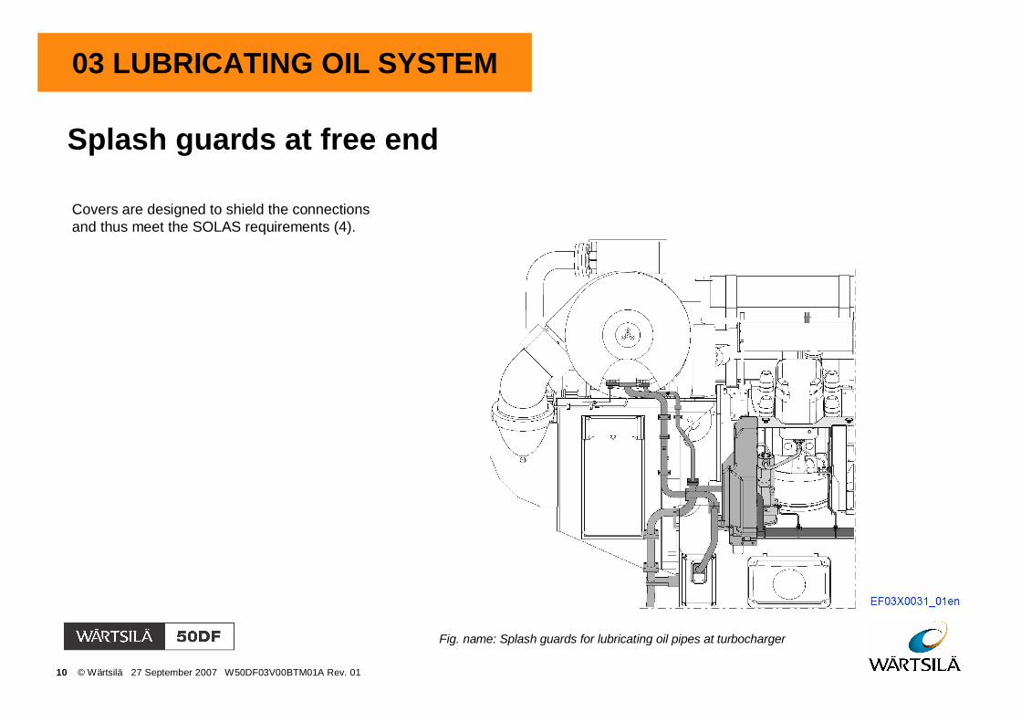
Splash guards at free end
Fig. name: Splash guards for lubricating oil pipes at turbocharger
Covers are designed to shield the connectionsand thus meet the SOLAS requirements (4).
11 © Wärtsilä 27 September 2007 W50DF03V00BTM01A Rev. 01
03 LUBRICATING OIL SYSTEM
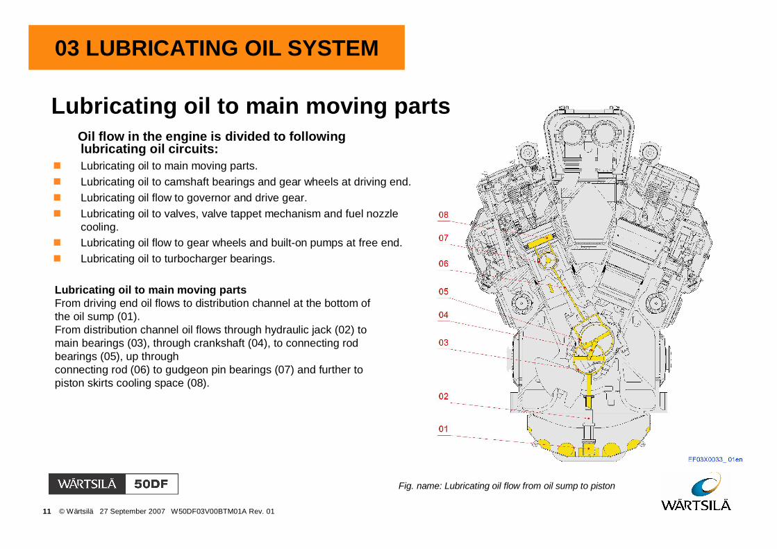
Lubricating oil to main moving parts
Fig. name: Lubricating oil flow from oil sump to piston
Lubricating oil to main moving partsFrom driving end oil flows to distribution channel at the bottom ofthe oil sump (01).From distribution channel oil flows through hydraulic jack (02) tomain bearings (03), through crankshaft (04), to connecting rodbearings (05), up throughconnecting rod (06) to gudgeon pin bearings (07) and further topiston skirts cooling space (08).
Oil flow in the engine is divided to followinglubricating oil circuits:Lubricating oil to main moving parts.Lubricating oil to camshaft bearings and gear wheels at driving end.Lubricating oil flow to governor and drive gear.Lubricating oil to valves, valve tappet mechanism and fuel nozzlecooling.Lubricating oil flow to gear wheels and built-on pumps at free end.Lubricating oil to turbocharger bearings.

12 © Wärtsilä 27 September 2007 W50DF03V00BTM01A Rev. 01
03 LUBRICATING OIL SYSTEM
Lubricating oil to main moving parts
Fig. name: Lubricating oil flow in piston
Part of the lubricating oil through connecting rod (01)flows out from piston skirt through the special nozzles(02) to cylinder liner, forming an oil film betweenpiston and cylinder liner surfaces. From the cylinderliner oil is drained back to oil sump.
Lubricating oil flow in piston

13 © Wärtsilä 27 September 2007 W50DF03V00BTM01A Rev. 01
03 LUBRICATING OIL SYSTEM
Lubricating oil flow at driving end
System components01 Cover for camshaft02 Cover for intermediate gear03 Lubricating nozzle for gear
Pipe connectionsA Lubricating oil inlet to camshaft drive gear bearingB Lubricating oil inlet to intermediate gear bearingC Lubricating oil supply to governor drive and gears
Fig. name: Lubricating oil flow at driving end
The oil circuit consists of lubricating oil pipes and oil channels forcamshaft drive gears and intermediate gears.
Part of the lubricating oil flow is branched for lubrication of the gearwheels by special lubricating oil nozzle pipes (03). The nozzle pipesinclude small nozzle holes where out coming lubricating oil jetlubricates the gear wheels.

14 © Wärtsilä 27 September 2007 W50DF03V00BTM01A Rev. 01
03 LUBRICATING OIL SYSTEM
Oil flow to intermediate gear wheel bearing
System components01 Bigger intermediate gear wheel02 Smaller intermediate gear wheel03 Intermediate gear bearing04 Thrust bearing
ConnectionsA Oil flow to bearingB Oil drain to sump
Fig. name: Oil flow to intermediate gear wheel bearing
From lubricating oil piping oil flows through channels ofcover to thrust bearing and further to intermediate gear.Through channels of intermediate gear oil flows tobearings and back to oil sump.

15 © Wärtsilä 27 September 2007 W50DF03V00BTM01A Rev. 01
03 LUBRICATING OIL SYSTEM
Oil flow to camshaft driving gear bearing
System components01 Camshaft driving gear wheel03 Camshaft driving gear bearing04 Thrust bearing
Pipe connectionsA Oil flow to bearingB Oil drain to sump
Fig. name: Oil flow to camshaft drive gear bearing
From lubricating oil piping oil flows through channels ofcover to bearing and camshaft end. Through channels oilflows back to oil sump.
16 © Wärtsilä 27 September 2007 W50DF03V00BTM01A Rev. 01
03 LUBRICATING OIL SYSTEM
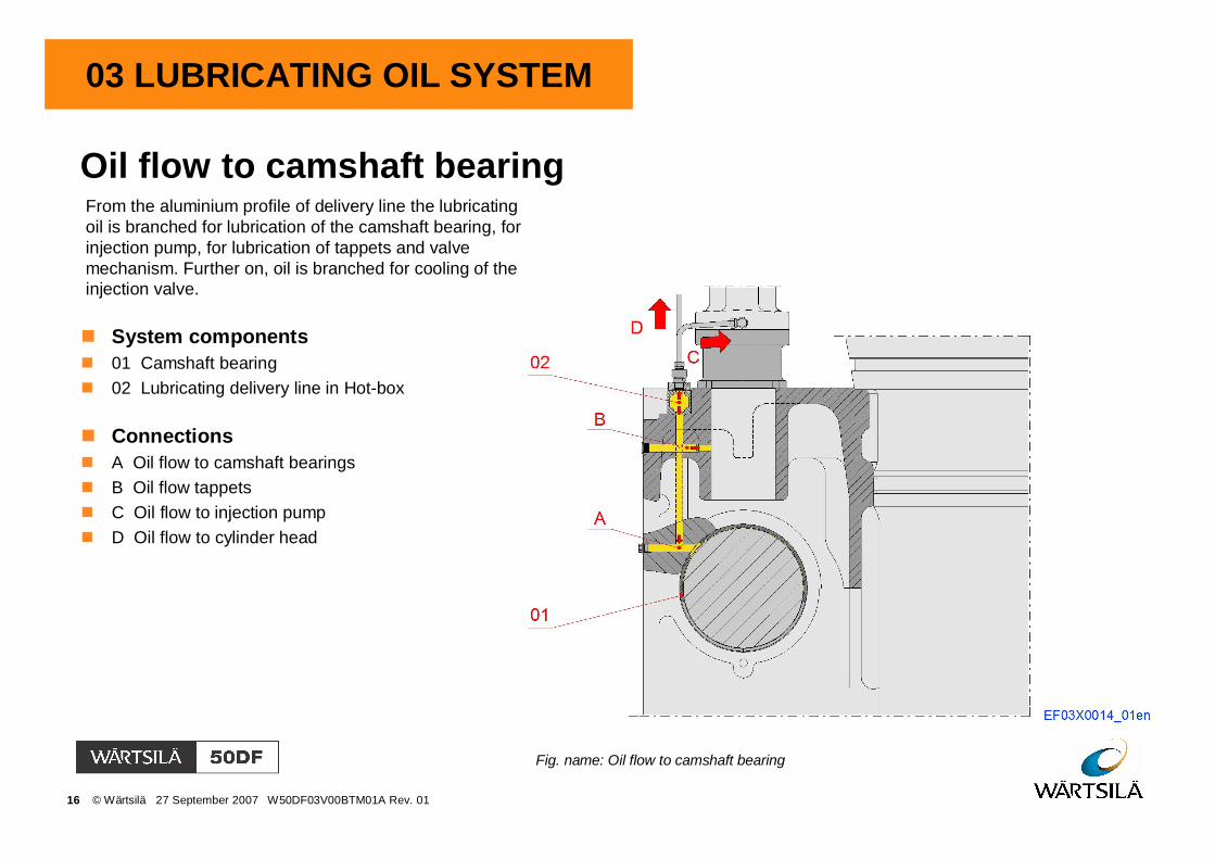
Oil flow to camshaft bearing
System components01 Camshaft bearing02 Lubricating delivery line in Hot-box
ConnectionsA Oil flow to camshaft bearingsB Oil flow tappetsC Oil flow to injection pumpD Oil flow to cylinder head
Fig. name: Oil flow to camshaft bearing
From the aluminium profile of delivery line the lubricatingoil is branched for lubrication of the camshaft bearing, forinjection pump, for lubrication of tappets and valvemechanism. Further on, oil is branched for cooling of theinjection valve.

17 © Wärtsilä 27 September 2007 W50DF03V00BTM01A Rev. 01
03 LUBRICATING OIL SYSTEM
Lubricating oil to governor drive and gear wheels
System components01 Lubricating oil nozzle for gears
ConnectionsC Lubricating oil inlet to governor drive
Fig. name: Lubricating oil flow to governor drive and gear wheels
The governor drive bearings and drive gears arelubricated by the engine internal lubricating oil system.The system consists of the suction oil pipe connected tothe governor drive housing, oil pipes for the drive bearingsand lubricating oil nozzle pipes for drive gears.
Oil is supplied by special oil nozzle pipes from the oilcirculating system to the drive gear wheels and bearingsof governor drive. The nozzle pipes include small nozzleholes from where a forced lubricating oil jet lubricates thegear wheels.

18 © Wärtsilä 27 September 2007 W50DF03V00BTM01A Rev. 01
03 LUBRICATING OIL SYSTEM
Lubricating oil to governor drive and gear wheels
System components01 Lubricating oil nozzle for gears
ConnectionsA Oil flow to bearingsB Oil drain to sumpC Oil flow to nozzle
Fig. name: Lubricating oil flow to governor drive
The oil from the engine internal lubricating oil systemflows through internal channels of governor drive tobearings and drains to sump.Lubricating oil nozzles lubricate gear wheels.

19 © Wärtsilä 27 September 2007 W50DF03V00BTM01A Rev. 01
03 LUBRICATING OIL SYSTEM
Oil flow to valve tappets and injection tappet
Fig. name: Oil flow to valve tappets and injection tappet and pump
From the aluminium profile manifold in the Hot-box onthe engine block the lubricating oil is led for tappetsassembly through oil channels of engine block.Lubrication of injection pump is arranged via lubricatingpipe connection.After circulation the oil then returns to the oil sump.
ConnectionsB Oil flow to injection tappets and valve tappetsC Oil flow to injection pump push rod

20 © Wärtsilä 27 September 2007 W50DF03V00BTM01A Rev. 01
03 LUBRICATING OIL SYSTEM
Oil flow to valve mechanism and injection valve
System components01 Push rod02 Rocker arm03 Yoke04 Valve rotator05 Valve and valve guide06 Injection valve
Pipe connectionsB Oil flow to injection valve coolingD Oil inlet connection
Fig. name: Oil flow to valve mechanism and injection valve
The oil flows to the cylinder head through aconnection on the side of the cylinder head. Insideof the cylinder head oil flows through bore. And thencontinues up through the internal channels in therocker arms arrangement, through the yoke pins tothe top of the valves.The oil flow for the injection valve cooling isarranged via oil pipe to the top of valve body whereoil flows to the nozzle end and then returns to top ofthe cylinder head. The oil then is drained via thepush rod covering pipe through the valve tappetsassemblies and back to the oil sump.

21 © Wärtsilä 27 September 2007 W50DF03V00BTM01A Rev. 01
03 LUBRICATING OIL SYSTEM
Lubricating oil flow to gear wheels and built-on pumps atfree end
Fig. name: Lubricating oil pipes for gear wheels and built-on pumps
The system consists of the suction oil pipe from the oilinlet, oil pipes for the built-on pump bearings and gearwheels, and lubricating oil nozzle pipes.Oil is supplied by special oil nozzle pipes from thedischarge side of the lubricating oil pump to the drivegear wheels of the crankshaft and built-on pumps.The nozzle pipes include small nozzle holes throughwhich a forced lubricating oil jets feed the gear wheels.
System components16 Lubricating nozzle for driving gear17 Lubricating oil inlet for LT-water pump18 Lubricating oil inlet for HT-water pump19 Control pressure from delivery piping
22 © Wärtsilä 27 September 2007 W50DF03V00BTM01A Rev. 01
03 LUBRICATING OIL SYSTEM
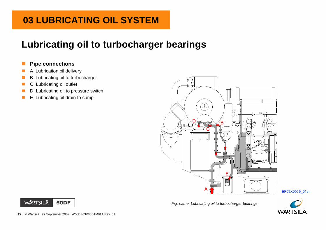
Lubricating oil to turbocharger bearings
Pipe connectionsA Lubrication oil deliveryB Lubricating oil to turbochargerC Lubricating oil outletD Lubricating oil to pressure switchE Lubricating oil drain to sump
Fig. name: Lubricating oil to turbocharger bearings

23 © Wärtsilä 27 September 2007 W50DF03V00BTM01A Rev. 01
03 LUBRICATING OIL SYSTEM
Lubricating oil pump
Fig. name: Lubricating oil pump
The lubricating oil pump is a screw pump with threescrew spindles, driving and two idler spindles. Thepump is dimensioned for actual lubricating oilviscosity.
The working parts of the pump are the three screwspindles, which rotate in the surrounding casing. Theliquid moves axially when the screws rotate and isforced hereby creating a pumping action.
The pump has an built-in pressure relief valve, whichfunctions as a safety valve for the pump. The pumplubrication is supplied by the pumped lubricating oil.
The pressure relief valve is designed for themaximum lubricating oil flow of the pump. When thepressure exceeds the adjusted values on thepressure side, the valve cone lifts from the seat andthe lubricating oil circulates into suction side of thepump casing. The opening pressure is adjusted bycompressing the valve spring with the adjustingscrew at the factory.
Pressure control valve of lubricating oil system isintegrated into pump housing.

24 © Wärtsilä 27 September 2007 W50DF03V00BTM01A Rev. 01
03 LUBRICATING OIL SYSTEM
Lubricating oil pumpComponents01 Set of spindles02 Adjusting screw03 Spring plate04 Valve spring05 Valve seat06 Valve cone07 Screw plug08 Sealing ring09 Gasket10 Gasket11 Screw plug12 Sealing ring15 Threaded pin
ConnectionsA Suction connectionC Pressure connection
Fig. name: Lubricating oil pump

25 © Wärtsilä 27 September 2007 W50DF03V00BTM01A Rev. 01
03 LUBRICATING OIL SYSTEM
Pressure control valve
Components01 Adjusting screw02 Pilot control piston03 Overload safety valve04 Main regulating piston05 Orifice06 Spring
Fig. name: Pressure control valve
The lubricating oil system is equipped with a pressureregulating valve to maintain the oil at a constantpressure to the engine lubrication oil feed pipe undervariable conditions (pressure changes after feed pump,pressure drop changes in coolers and filters etc.).If, for some reason, the pressure should increasestrongly in the pressure side, safety valve (03) will openand admits oil to pass to the regulating piston (02). Thisserves as a safety valve.
ConnectionsD Pressure connectionE Outlet connectionF Control pressure

26 © Wärtsilä 27 September 2007 W50DF03V00BTM01A Rev. 01
03 LUBRICATING OIL SYSTEM
Drive gear for lubricating oil pump
Fig. name: Drive gear for lubricating oil pump
The lubricating oil pump is driven by drive gearwheel at the end of crankshaft, which rotatespump mechanism. Gear wheel of pump ismounted with clamping rings.Pump is positioned correctly into pump coverwith flange of pump and fastened by screws.
Components01 Gear wheel02 Driving gear wheel03 Clamping ring, outer04 Clamping ring, inner05 Screw08 Screw09 Sealing ring

27 © Wärtsilä 27 September 2007 W50DF03V00BTM01A Rev. 01
03 LUBRICATING OIL SYSTEM
Running-in filter
Fig. name: Running-in filter
All engines are provided with full-flow filters. Thefilters are used only during running-in and at thefirst start-up of the installation.
The oil flows through the filter insert and dirtparticles are collected to filter insert. A safetyvalve is built into the middle of the lower endflange. This safety valve opens if the pressurerises too much and allows the oil to passthrough.
It is recommended to use running-in filters aftercertain maintenance operations, such as majorengine repairs and oil system maintenance orrepair.
The filters are usually removed by theinstallation personnel.
Components01 Filter cartridge02 Safety valve

28 © Wärtsilä 27 September 2007 W50DF03V00BTM01A Rev. 01
03 LUBRICATING OIL SYSTEM
Crankcase ventilation system
System components01 Valve plate02 Base for breather valve03 Oil lock for breather
Pipe connectionsA 717 Crankcase breather drain
Fig. name: Crankcase ventilation system arrangement
There is always an amount of vaporized oil in thecrankcase and it has to be ventilated out from theengine. Vaporized oil is led out by the ventilation pipemounted on the engine block.
Inside the ventilation pipe there is a valve plate wherevaporized oil is condensed.Condensed oil drains back to the crankcase and theremaining "dry" vaporized oil continues further up thepipe and out from the engine.