03-2 Fire Safety String-Final FS52-FS102
44
ICC PUBLIC HEARING ::: September 2006 IBC - FS61 Exceptions: 1. Enclosed elevator lobbies are not required at the street floor, provided the entire street floor is equipped with an automatic sprinkler system in accordance with Section 903.3.1.1. 2. Elevators not required to be located in a shaft in accordance with Section 707.2 are not required to have enclosed elevator lobbies. 3. Where additional doors are provided at the hoistway opening in accordance with Section 3002.6. Such doors shall be tested in accordance with UL 1784 without an artificial bottom seal. 4. In other than Group I-2 and I-3, and buildings having occupied floors located more than 75 feet (22 860 mm) above the lowest level of fire department vehicle access, enclosed elevator lobbies are not required where the building is protected by an automatic sprinkler system installed in accordance with Section 903.3.1.1 or 903.3.1.2. 5. Smoke partitions shall be permitted in lieu of fire partitions to separate the elevator lobby at each floor where the building is equipped throughout with an automatic sprinkler system installed in accordance with Section 903.3.1.1 or 903.3.1.2. 6. Enclosed elevator lobbies are not required where the elevator hoistway is pressurized in accordance with Section 707.14.2. Reason: The purpose of the elevator lobby is to prevent smoke migration between floors. This change would clarify that elevator shaft smoke protection is required in I-2 occupancies. Patients in hospitals and nursing homes are the least likely of building occupants to be able to provide self directed evacuation in a fire emergency. Currently the code requires the establishment of at least 2 smoke compartments on each floor which allows patients to be relocated to another area of the floor on the other side of the smoke barrier construction, however the elevator shaft penetrates the floor assemblies and the elevator hoistway doors allow excessive amounts of smoke to leak into the elevator shaft and then to other floors when the hoistway opening is not protected. Many states and local jurisdictions already enforce a requirement such as this based upon either protection of entrances into corridors from smoke migration or alternately the requirement that the smoke compartments must seal all openings (vertical and horizontal) against the movement of smoke. Adding the proposed language to Exception 4 would insure uniform enforcement. Cost Impact: The code change proposal will increase the cost of construction. There may be a cost increase in those jurisdictions not requiring this level of protection in I-2 occupancies now, however there is no cost increase for those jurisdictions already enforcing this requirement based upon other language in the IBC. Public Hearing: Committee: AS AM D Assembly: ASF AMF DF FS53–06/07 707.14.1 Proponent: Matthew Davy, Schirmer Engineering Corporation, Greenbelt, MD Revise as follows: 707.14.1 Elevator lobby. An enclosed elevator lobby shall be provided at each floor where an elevator shaft enclosure connects more than three stories. The lobby shall separate the elevator shaft enclosure doors from each floor by fire partitions equal to the fire-resistance rating of the corridor and the required opening protection. Elevator lobbies shall have at least one means of egress complying with Chapter 10 and other provisions within this code. Exceptions: 1. Enclosed elevator lobbies are not required at the street floor, provided the entire street floor is equipped with an automatic sprinkler system in accordance with Section 903.3.1.1. 2. Elevators not required to be located in a shaft in accordance with Section 707.2 are not required to have enclosed elevator lobbies. 3. Where additional doors are provided at the hoistway opening in accordance with Section 3002.6. Such doors shall be tested in accordance with UL 1784 without an artificial bottom seal. 4. In other than Group I-3, and buildings having occupied floors located more than 75 feet (22 860 mm) above the lowest level of fire department vehicle access, enclosed elevator lobbies are not required where the building is protected by an automatic sprinkler system installed in accordance with Section 903.3.1.1 or 903.3.1.2. 5. Smoke partitions shall be permitted in lieu of fire partitions to separate the elevator lobby at each floor where the building is equipped throughout with an automatic sprinkler system installed in accordance with Section 903.3.1.1 or 903.3.1.2. 6. Enclosed elevator lobbies are not required at each floor where the building is equipped throughout with an automatic sprinkler system installed in accordance with Section 903.3.1.1 or 903.3.1.2 and the fire areas served by the elevator shaft enclosure are required by this code to comply with Section 903.3.2.
Transcript of 03-2 Fire Safety String-Final FS52-FS102

ICC PUBLIC HEARING ::: September 2006 IBC - FS61
Exceptions:
1. Enclosed elevator lobbies are not required at the street floor, provided the entire street floor is equipped with an automatic sprinkler system in accordance with Section 903.3.1.1.
2. Elevators not required to be located in a shaft in accordance with Section 707.2 are not required to have enclosed elevator lobbies.
3. Where additional doors are provided at the hoistway opening in accordance with Section 3002.6. Such doors shall be tested in accordance with UL 1784 without an artificial bottom seal.
4. In other than Group I-2 and I-3, and buildings having occupied floors located more than 75 feet (22 860 mm) above the lowest level of fire department vehicle access, enclosed elevator lobbies are not required where the building is protected by an automatic sprinkler system installed in accordance with Section 903.3.1.1 or 903.3.1.2.
5. Smoke partitions shall be permitted in lieu of fire partitions to separate the elevator lobby at each floor where the building is equipped throughout with an automatic sprinkler system installed in accordance with Section 903.3.1.1 or 903.3.1.2.
6. Enclosed elevator lobbies are not required where the elevator hoistway is pressurized in accordance with Section 707.14.2.
Reason: The purpose of the elevator lobby is to prevent smoke migration between floors. This change would clarify that elevator shaft smoke protection is required in I-2 occupancies.
Patients in hospitals and nursing homes are the least likely of building occupants to be able to provide self directed evacuation in a fire emergency. Currently the code requires the establishment of at least 2 smoke compartments on each floor which allows patients to be relocated to another area of the floor on the other side of the smoke barrier construction, however the elevator shaft penetrates the floor assemblies and the elevator hoistway doors allow excessive amounts of smoke to leak into the elevator shaft and then to other floors when the hoistway opening is not protected.
Many states and local jurisdictions already enforce a requirement such as this based upon either protection of entrances into corridors from smoke migration or alternately the requirement that the smoke compartments must seal all openings (vertical and horizontal) against the movement of smoke. Adding the proposed language to Exception 4 would insure uniform enforcement. Cost Impact: The code change proposal will increase the cost of construction. There may be a cost increase in those jurisdictions not requiring this level of protection in I-2 occupancies now, however there is no cost increase for those jurisdictions already enforcing this requirement based upon other language in the IBC. Public Hearing: Committee: AS AM D Assembly: ASF AMF DF
FS53–06/07 707.14.1 Proponent: Matthew Davy, Schirmer Engineering Corporation, Greenbelt, MD Revise as follows: 707.14.1 Elevator lobby. An enclosed elevator lobby shall be provided at each floor where an elevator shaft enclosure connects more than three stories. The lobby shall separate the elevator shaft enclosure doors from each floor by fire partitions equal to the fire-resistance rating of the corridor and the required opening protection. Elevator lobbies shall have at least one means of egress complying with Chapter 10 and other provisions within this code.
Exceptions:
1. Enclosed elevator lobbies are not required at the street floor, provided the entire street floor is equipped with an automatic sprinkler system in accordance with Section 903.3.1.1.
2. Elevators not required to be located in a shaft in accordance with Section 707.2 are not required to have enclosed elevator lobbies.
3. Where additional doors are provided at the hoistway opening in accordance with Section 3002.6. Such doors shall be tested in accordance with UL 1784 without an artificial bottom seal.
4. In other than Group I-3, and buildings having occupied floors located more than 75 feet (22 860 mm) above the lowest level of fire department vehicle access, enclosed elevator lobbies are not required where the building is protected by an automatic sprinkler system installed in accordance with Section 903.3.1.1 or 903.3.1.2.
5. Smoke partitions shall be permitted in lieu of fire partitions to separate the elevator lobby at each floor where the building is equipped throughout with an automatic sprinkler system installed in accordance with Section 903.3.1.1 or 903.3.1.2.
6. Enclosed elevator lobbies are not required at each floor where the building is equipped throughout with an automatic sprinkler system installed in accordance with Section 903.3.1.1 or 903.3.1.2 and the fire areas served by the elevator shaft enclosure are required by this code to comply with Section 903.3.2.

IBC - FS62 ICC PUBLIC HEARING ::: September 2006
6. 7. Enclosed elevator lobbies are not required where the elevator hoistway is pressurized in accordance with Section 707.14.2.
Reason: The purpose of the proposed code change is to add a new exception that allows an elevator lobby to be open to a floor if the building is fully sprinklered and the fire areas served by the elevator shaft enclosure are required to be provided with quick-response or residential sprinkler heads.
It has been well established and stated in the IBC Commentary that “elevator shafts create a passage for the accumulation and spread of hot smoke and gases from a fire to upper stories of a building via stack effect. During a fire, the presence of stack effect generally results in the movement of smoke and combustion products from lower levels to upper levels through shafts in the building.” However, as also stated in the IBC Commentary, “the potential for smoke migration via the stack effect is reduced by a sprinkler system.” Therefore, a sprinkler system, coupled with quick-response or residential sprinklers, creates a scenario where smoke movement is not a significant problem that results in an untenable situation.
The IBC Commentary for Section 903.3.2 states that this section “requires the use of either listed quick-response or residential automatic sprinklers depending upon the type of sprinkler system required to facilitate faster and more effective suppression in certain areas. Residential sprinklers are required in all types of residential buildings that would permit the use of an NFPA 13R sprinkler system.”
Light Hazard occupancies as defined in NFPA 13 “shall be defined as occupancies or portions of other occupancies where the quantity and/or combustibility of contents is low and fires with relatively low rates of heat release are expected.” Light hazard occupancies include occupancies having uses and conditions similar to the following:
Churches (IBC Group A-3) Clubs (IBC Group A-2) Educational (IBC Group E) Hospitals (IBC Group I-2) Institutional (IBC Group I-3) Libraries, except large stack rooms (IBC Group A-3) Museums (IBC Group A-3) Nursing or convalescent homes (IBC Group I-1) Offices, including data processing (IBC Group B) Residential (IBC Group R) Restaurant seating areas (IBC Group A-3) Theaters and auditoriums, excluding stages and prosceniums (IBC Group A-1)
Therefore, it can be realistically assumed that the light hazard occupancy includes Group A, B, E, I and R occupancies. In the article by Bukowski, he indicates “as expected, sprinklered fires were not shown to represent a significant hazard to occupants because
the sprinklers activated and extinguished the fires before they could release significant energy or mass. Little or no smoke or gasses entered the hoistways, and none reached remote locations in any building regardless of height or other conditions examined.” Later, Bukowski clearly states “it may be concluded [ ] that enclosed elevator lobbies are not necessary in building with operational fire sprinkler systems.” The new installation of an automatic sprinkler system is required by IBC Section 903.4 to be monitored at all valves and water-flow switches and have audible alarms located on the exterior of the building. Overall, the fire protection system requirements for buildings constructed using the IBC have evolved and provide a holistic protection scheme. Therefore, this proposed code change proposal will reduce the conservative elevator lobby requirements by acknowledging the installation and effectiveness of automatic sprinkler systems in light hazard occupancies. Bibliography: Bukowski, R.W., Is There A Need to Enclose Elevator Lobbies In Tall Buildings?, Building Safety Journal, pg. 26-31, August 2005. Cost Impact: The code change proposal will not increase the cost of construction. Analysis: A copy of the article Is There A Need to Enclose Elevator Lobbies in Tall Buildings? Is available for review at http://www.iccsafe.org/news/bsj Public Hearing: Committee: AS AM D Assembly: ASF AMF DF
FS54–06/07 707.14.1 Proponent: Dave Frable, U.S. General Services Administration, representing U.S. General Services Administration Revise as follows: 707.14.1 Elevator lobby. An enclosed elevator lobby shall be provided at each floor where an elevator shaft enclosure connects more than three stories. The lobby shall separate the elevator shaft enclosure doors from each floor by fire partitions equal to the fire-resistance rating of the corridor and the required opening protection. Elevator lobbies shall have at least one means of egress complying with Chapter 10 and other provisions within this code.
Exceptions:
1. Enclosed elevator lobbies are not required at the street floor, provided the entire street floor is equipped with an automatic sprinkler system in accordance with Section 903.3.1.1.
2. Elevators not required to be located in a shaft in accordance with Section 707.2 are not required to have enclosed elevator lobbies.
3. Where additional doors are provided at the hoistway opening in accordance with Section 3002.6. Such doors shall be tested in accordance with UL 1784 without an artificial bottom seal.
4. In other than Group I-3, and buildings having occupied floors located more than 75 feet (22 860 mm) above the lowest level of fire department vehicle access, enclosed elevator lobbies are not required where the building is protected by an automatic sprinkler system installed in accordance with Section 903.3.1.1 or 903.3.1.2.

ICC PUBLIC HEARING ::: September 2006 IBC - FS63
5. Enclosed elevator lobbies are not required to be installed in Group B occupancies that are more than 75 feet in height above the lowest level of fire department vehicle access, and are protected throughout by an automatic fire sprinkler system designed and installed in accordance with Section 903.3.1.1 and maintained in accordance with Section 903.5.
5. 6. Smoke partitions shall be permitted in lieu of fire partitions to separate the elevator lobby at each floor where the building is equipped throughout with an automatic sprinkler system installed in accordance with Section 903.3.1.1 or 903.3.1.2.
6. 7. Enclosed elevator lobbies are not required where the elevator hoistway is pressurized in accordance with Section 707.14.2.
Reason: The purpose of this code change is to acknowledge that Group B occupancies protected by an operational automatic fire sprinkler system provide an acceptable level of safety for building occupants and therefore do not warrant the need for enclosed elevator lobbies.
Previous research conducted by the National Institute of Standards and Technology (NIST) with consultation by Dr. John Klote, has shown that sprinklered fires do not represent a significant hazard to the building occupants because the automatic sprinklers activated and extinguished the fire prior to releasing a significant energy or mass. Little or no smoke or gases entered the hoistways, and none reached remote locations in any building regardless of height or other conditions examined.
Therefore, it can be concluded that smoke spread in shafts and elevator hoistways is not a problem in Group B occupancies protected throughout with an operational fire sprinkler system since the fire sprinklers both control the burning rate (and thus limit smoke production) and maintain near ambient temperature which limits the buoyancy forces that drive smoke to the shafts where stack affect may cause smoke spread to other floors. It is also widely accepted that operating fire sprinklers will prevent room flashover and full floor fires, and will limit the size of room fires2. This conclusion can also be substantiated from a paper presented by Dr. John Klote at the Elevator Symposium on Emergency Use of Elevators in March 2004 and in an article titled “Is There A Need to Enclose Elevator Lobbies In Tall Buildings?”, written by Richard Bukowski in the August 2005 Building Safety Journal.
In addition, all high-rise fires where smoke spread has been a problem have either been in unsprinklered buildings or partially sprinklered buildings. A recent comprehensive analysis in 2005 of high-rise fires by NFPA identified that no fatalities had occurred for more than a decade in any U.S. high-rise occupancy (> 10 story) other than the 6 fatalities in the unsprinklered Cook County Office Building (2003); the 1 fatality in the unsprinklered First Interstate Bank Building (1991); and 3 firefighter fatalities in the partially sprinklered (unsprinklered on floor of fire origin and several floors above) Meridan Plaza Building (1991). The Murrah Federal Building (1995) and the World Trade Center (1993 & 2001) bombings were excluded from this analysis.
The recently issued NFPA 2005 report on sprinkler reliability also indicated that automatic fire sprinklers successfully operating in reported structural fires was an exemplary 93%. In addition, NFPA also reported that two-thirds of the reported automatic fire sprinkler system failures were because the automatic fire sprinkler systems were shut off.4 Since the IBC requires the supervision of the automatic fire sprinkler system, one can conclude that the successful operation of an automatic fire sprinkler system designed and installed in compliance with the IBC requirements could be reasonably estimated at 98%. NFPA also reported that the percentage of successfully operating automatic fire sprinkler systems is probably higher since a large percentage of small fire extinguished by fire sprinklers are not reported. Therefore, for an automatic fire sprinkler system designed and installed in accordance with the IBC requirements, the successful operation of an automatic fire sprinkler system could be reasonably estimated at 98% or more.
Please also keep in mind that the purpose of the International Building Code is to provide minimum requirements to safeguard occupants of buildings from fire and other hazards attributed to the built environment that are based on sound technical documentation. Also keep in mind that fatalities are very rare in office buildings, even rarer in high-rise office buildings, and surpassingly rare in high-rise office buildings protected with an operational fire sprinkler system.
Last but not least, it should be noted that a similar proposal regarding the enclosure of elevator lobbies was also addressed by the National Fire Protection Association (NFPA) 101 Technical Committee on Industrial, Storage, and Miscellaneous (e.g., High-rise) Occupancies. The NFPA Technical Committee did not approve the proposal to separate elevator hoistways with smoke barriers in sprinkler high-rise buildings based on a lack of technical substantiation. In addition, on June 9, 2005 the NFPA membership approved the 2006 edition of NFPA 101 and supported the Technical Committee’s decision to not include a requirement to separate elevator hoistways with smoke barriers in sprinkler high-rise buildings.
Based on all these points stated above, we strongly believe that it unreasonable to state that Group B occupancies protected throughout with automatic fire sprinkler system is not a rationale alternative to enclosed elevator lobbies and that automatic fire sprinklers are not an effective method for slowing or stopping the spread of smoke throughout a building protected throughout with an operational automatic fire sprinkler system. In addition, we believe the current requirement for enclosing elevator lobbies in Group B occupancies, protected throughout by an operational automatic fire sprinkler system has not been based on sound technical documentation and will significantly increase building construction and maintenance costs without increasing the overall safety to the building occupants. References: Klote, J.H., Analysis of the Consequences of Smoke Migration through Elevator Shafts, Use of Elevators in Fires and Other Emergencies Workshop. Proceedings. Co-Sponsored by American Society of Mechanical Engineers (ASME International); National Institute of Standards and Technology (NIST); International Code Council (ICC); National Fire Protection Association (NFPA); U.S. Access Board and International Association of Fire Fighters (IAFF). March 2-4, 2004, Atlanta, GA, Guide on Methods for Evaluating Potential for Room Flashover, NFPA 555 2000 ed., Nat Fire Prot Assn, Quincy, MA. Bukowski, R. W., Is There A Need to Enclose Elevator Lobbies In Tall Buildings?, Building Safety Journal, 26-31 pp, August 2005. Rohr, K.D and Hall, J.R., Jr., U.S. Experience With Sprinklers and Other Fire Extinguishing Equipment, August 2005. Cost Impact: The code change proposal will not increase the cost of construction. Public Hearing: Committee: AS AM D Assembly: ASF AMF DF
FS55–06/07 707.14.2.1 Proponent: Bill Ziegert, Smoke Guard, division of RectorSeal Revise as follows: 707.14.2.1 Pressurization requirements. Elevator hoistways shall be pressurized to maintain a minimum positive pressure of 0.04 inches of water column and a maximum positive pressure of 0.06 inches of water column with respect to adjacent occupied space on all floors. This pressure shall be measured at the midpoint of each hoistway door, with
IBC - FS64 ICC PUBLIC HEARING ::: September 2006
all ground floor level hoistway doors open and all other hoistway doors closed, and the opening and closing of hoistway doors at each level must be demonstrated during this test. The supply air intake shall be from an outside, uncontaminated source located a minimum distance of 20 feet (6096 mm) from any air exhaust system or outlet. Reason: The purpose of this change is to ensure the proper operation of the hoistway doors when the shaft pressurization system is activated and the Firefighters are using the elevators in Phase 2 service.
Elevator shaft pressurization systems are difficult to design due to the variable leakage rates through hoistway doors. As a result of this the system design at times results in excessive pressures at some floors in order to achieve the minimum pressure differentials at all floors. The result of this over pressurization can be binding of the hoistway’s doors during opening and closing operation resulting in sticking in a partially open position which places the emergency responders in the Elevator at risk. Cost Impact: The code change proposal will not increase the cost of construction. Public Hearing: Committee: AS AM D Assembly: ASF AMF DF
FS56–06/07 707.14.2.1 Proponent: Janet Reed, City of Phoenix, AZ – Development Services Department Revise as follows: 707.14.2.1 Pressurization requirements. Elevator hoistways shall be pressurized to maintain a minimum positive pressure of 0.04 0.05 inches of water column and a maximum positive pressure of 0.06 inches of water column as allowed by the elevator door manufacturer’s specifications with respect to adjacent occupied space on all floors. This pressure shall be measured at the midpoint of each hoistway door, with all ground floor level elevator cars at the floor of recall and all hoistway doors on the floor of recall open and all other hoistway doors closed. The supply air intake shall be from an outside, uncontaminated source located a minimum distance of 20 feet (6096 mm) from any air exhaust system or outlet. Reason: As written, this code would be extremely difficult to implement if not impossible.
The narrow pressure range prescribed, 0.04 to 0.06 inches H2O, is approximately the range of stack effect that could be experienced per floor when inside temperature is 70 degrees Fahrenheit greater than outside. Under this condition it would require a system capable of providing a pressurized air supply injection and relief venting capability at each floor in the elevator shaft to maintain the 0.02 inches H2O range of pressure called for. Furthermore, the minimum of 0.04 inches water column is less than the smoke barrier minimum of 0.05 inches water column called for elsewhere in this code and numerous other codes. The current code requires ground floor doors to be open under the apparent assumption that the ground floor is always the floor of recall. This is not always true, in fact in some express arrangements some elevators don't even go to the ground floor. It is therefore prescribed that the cars be at the floor of recall with those doors open.
A lower limit of 0.05 inches of water column would satisfy the minimum required for smoke barriers in Section 909.6.1. The upper limit would give enough range to allow a reasonable number of injection points and relief dampers to maintain the prescribed pressures. The maximum based on manufacturer's specifications would ensure that the system could be designed with the greatest flexibility while avoiding conditions that impair elevator operations. The rational analysis would then need to include the manufacturer's specifications. Cost Impact: The code change proposal will not increase the cost of construction. Public Hearing: Committee: AS AM D Assembly: ASF AMF DF
FS57–06/07 707.14.2.1.1 (New) Proponent: Gregory J. Cahanin, Cahanin Fire & Code Consulting, representing Smoke Safety Council Add new text as follows: 707.14.2.1 Pressurization requirements. Elevator hoistways shall be pressurized to maintain a minimum positive pressure of 0.04 inches of water column and a maximum positive pressure of 0.06 inches of water column with respect to adjacent occupied space on all floors. This pressure shall be measured at the midpoint of each hoistway door, with all ground floor level hoistway doors open and all other hoistway doors closed. The supply air intake shall be from an outside, uncontaminated source located a minimum distance of 20 feet (6096 mm) from any air exhaust system or outlet. 707.14.2.1.1 The pressurization of the hoistway shall not result in a maximum positive pressure greater than 0.10 inches of water column across any hoistway door opening. Reason: The proper design of a hoistway pressurization system will result in varying pressures at elevator doors throughout the shaft depending upon variables that include the introduction point of the pressurization system, the location of relief vents, wind loads, stack effect, and piston effect. It is not only important that minimum pressures across elevator doors be maintained, but also that pressure is not so high on some doors that they will fail to open.
ICC PUBLIC HEARING ::: September 2006 IBC - FS65
The ASHRAE/SFPE Principals of Smoke Management Manual in the chapter on Elevator Smoke Control points to a concern that shaft pressurization could result in elevator doors jamming and effecting the movement of elevator cars. In field tests conducted by John Klote and detailed in the ASHRAE Journal (1984) door jamming was encountered at higher pressure differentials.
Elevators provide for egress of occupants with mobility impairments, firefighter ingress for staging and for rescue. The operation of elevator doors is critical to these activities. This change will insure that the installation, as designed, will perform in a fire emergency. The primary purpose of this change is to provide reliable operation of elevator hoistway doors during Phase II emergency operation. Failure of hoistway doors to open while firefighters are performing rescue and staging operations during a fire would put firefighters at greater risk.
Cost Impact: The code change proposal will not increase the cost of construction. Public Hearing: Committee: AS AM D Assembly: ASF AMF DF
FS58–06/07 707.14.2.1.1, 707.14.2.1.1 (New) Proponent: Gregory J. Cahanin, Cahanin Fire & Code Consulting, representing Smoke Safety Council Revise as follows: 707.14.2.1 Pressurization requirements. Elevator hoistways shall be pressurized to maintain a minimum positive pressure of 0.04 inches of water column and a maximum positive pressure of 0.06 inches of water column with respect to adjacent occupied space on all floors above the maximum probable stack effect pressure. This pressure shall be measured at the midpoint of each hoistway door, with all ground floor level hoistway doors open and all other hoistway doors closed. The supply air intake shall be from an outside, uncontaminated source located a minimum distance of 20 feet (6096 mm) from any air exhaust system or outlet. 707.14.2.1.1 The maximum probable normal or reverse stack effect pressure shall be determined using altitude, elevation, weather history and interior temperatures. Reason: The new requirements for pressurization failed to take into account a building’s stack effect pressure that could be greater than the hoistway pressurization system rendering it ineffective. The pressure differential from the elevator shaft to the floor must be greater than the stack effect. The fire pressure on the fire floor must be less than the hoistway pressure in order for a differential to exist. Table 5.1 of the ASHRAE/SFPE Principals of Smoke Management Manual lists fire differential pressures of 0.05 to 0.11 inches of water.
The new 707.14.2.1.1 is taken from the language in Section 909.4.1 smoke control requirements now in the code. For northern climates stack effect in the winter would be the most severe anticipated condition for challenging the hoistway pressurization system. For southern climates where reverse stack effect is a greater concern the summer temperature would be utilized. Stack effect has been used in Section 909 for several editions of the IBC and is an accepted term in smoke control.
The ASHRAE/SFPE Principals of Smoke Management Manual provides nationally accepted methods of designing elevator pressurization systems as well as a calculative methodology for design of the system to be confirmed during acceptance testing. Testing would not have to be performed on a mean low or high temperature day, but could have collected data adjusted for more conservative mean temperature conditions to determine performance and system acceptance. Cost Impact: The code change proposal will not increase the cost of construction. Public Hearing: Committee: AS AM D Assembly: ASF AMF DF
FS59–06/07 707.14.2.2.1 (New), 3004.2 Proponent: Gregory J. Cahanin, Cahanin Fire & Code Consulting, representing Smoke Safety Council THIS PROPOSAL IS ON THE AGENDA OF THE IBC FIRE SAFETY AND THE IBC GENERAL CODE DEVELOPMENT COMMITTEES. SEE THE TENTATIVE HEARING ORDERS FOR THESE COMMITTEES. PART I – IBC FIRE SAFETY Add new text as follows: 707.14.2.2 Ducts for system. Any duct system that is part of the pressurization system shall be protected with the same fire-resistance rating as required for the elevator shaft enclosure. 707.14.2.2.1 Ducts. Ducts shall open either directly to the outer air or through noncombustible ducts to the outer air. Noncombustible ducts shall be permitted to pass through the elevator machine room provided that portions of the ducts located outside the hoistway or machine room are enclosed by construction having not less than the fire resistance rating required for the hoistway. PART II – IBC GENERAL Revise as follows: 3004.2 Location of vents. Vents shall be located at the top the hoistway and shall open either directly to the outer air through noncombustible ducts to the outer air. Noncombustible ducts shall be permitted to pass through the elevator

IBC - FS66 ICC PUBLIC HEARING ::: September 2006
machine room, provided that portions of the ducts located outside the hoistway or machine room are enclosed by construction having not less than the fire protection resistance rating required for the hoistway. Holes in the machine room floors for the passage of ropes, cables or other moving elevator equipment shall be limited as not to provide greater than 2 inches (51 mm) of clearance on all sides. Reason: This new section provides fire-resistance requirements equal to those now mandated for hoistway vents.
Section 3004.2 for location of Hoistway Vents contains specific requirements for ducting of vents. The new 707.14.2.2 section does not contain requirements equal to the compartmentation requirements established for the Hoistway itself when the hoistway penetrates more than three floors. New language is taken directly from 3004.2 and changed as appropriate for shaft pressurization ducts connecting to the hoistway shaft.
This change brings continuity to the isolation of shaft pressurization systems for elevator shafts that are established elsewhere in the IBC and clarifies the intent of the original proposal. Cost Impact: The code change proposal will increase the cost of construction. PART I – IBC FIRE SAFETY Public Hearing: Committee: AS AM D Assembly: ASF AMF DF PART II – IBC GENERAL Public Hearing: Committee: AS AM D Assembly: ASF AMF DF
FS60–06/07 707.14.2.3.3 Proponent: Edward A. Donoghue, Edward A. Donoghue Associates, Inc., representing National Elevator Industry, Inc. Revise as follows: 707.14.2.3.3 Separate systems. A separate fan system shall be used for each bank of elevators hoistway. Reason: The purpose of this code change is to correct an apparent mistake in the 2006 code. A “bank of elevators” is a group of elevators or a single elevator controlled by a common operating system; that is, all those elevators that respond to a single call button constitute a bank of elevators. There is no limit on the number of elevator cars that may be in a bank or group, but there may not be more than four elevator cars within a common hoistway (Section 3002.2). A hoistway is constructed as a shaft (Section 3002.1) and would be separated from all other hoistways. The code will require at least two separate hoistways where four or more elevator cars serve all or the same portion of a building. It would therefore appear to be better, and also the intent, that a separate fan system be provided for each separate hoistway (shaft enclosure) instead of allowing a single fan to serve multiple hoistways. The redundancy of protection provided by having a separate fan serve each separate hoistway enclosure will provide a higher margin of safety than allowing a single fan to serve an entire bank of elevators. As the text is currently written, most buildings would only have a single fan system. The revision would mean that in a building where four or more elevator cars were installed which served the same portion of a building, at least two fan systems would be installed so that each separate hoistway (shaft enclosure) would be independently protected. Cost Impact: This code change proposal will increase the cost of construction by possibly requiring additional fans. This increase may be somewhat offset because the cost of a smaller fan should be less than a large fan. Public Hearing: Committee: AS AM D Assembly: ASF AMF DF
FS61–06/07 707.14.2.6 (New), 707.14.2.7 (New) Proponent: Gregory J. Cahanin, Cahanin Fire & Code Consulting, representing Smoke Safety Council Add new text as follows: 707.14.2 Enclosed elevator lobby pressurization alternative. Where elevator hoistway pressurization is provided in lieu of required enclosed elevator lobbies, the pressurization system shall comply with this section. 707.14.2.1 Pressurization requirements. Elevator hoistways shall be pressurized to maintain a minimum positive pressure of 0.04 inches of water column and a maximum positive pressure of 0.06 inches of water column with respect to adjacent occupied space on all floors. This pressure shall be measured at the midpoint of each hoistway door, with all ground floor level hoistway doors open and all other hoistway doors closed. The supply air intake shall be from an outside, uncontaminated source located a minimum distance of 20 feet (6096 mm) from any air exhaust system or outlet. 707.14.2.2 Ducts for system. Any duct system that is part of the pressurization system shall be protected with the same fire-resistance rating as required for the elevator shaft enclosure.
ICC PUBLIC HEARING ::: September 2006 IBC - FS67
707.14.2.3 Fan system. The fan system provided for the pressurization system shall be as required by this section. 707.14.2.3.1 Fire resistance. When located within the building, the fan system that provides the pressurization shall be protected with the same fire-resistance rating required for the elevator shaft enclosure. 707.14.2.3.2 Smoke detection. The fan system shall be equipped with a smoke detector that will automatically shut down the fan system when smoke is detected within the system. 707.14.2.3.3 Separate systems. A separate fan system shall be used for each bank of elevators. 707.14.2.3.4 Fan capacity. The supply fan shall either be adjustable with a capacity of at least 1,000 cfm (.4719 m3/s) per door, or that specified by a registered design professional to meet the requirements of a designed pressurization system. 707.14.2.4 Standby power. The pressurization system shall be provided with standby power from the same source as other required emergency systems for the building. 707.14.2.5 Activation of pressurization system. The elevator pressurization system shall be activated upon activation of the building fire alarm system or upon activation of the elevator lobby smoke detectors. 707.14.2.6 Acceptance testing to verify system performance shall be in accordance with Section 909.18. 707.14.2.7 System acceptance shall be in accordance with Section 909.19. Reason: The new requirements for hoistway pressurization systems do not contain specific acceptance testing and system acceptance requirements for both the contractor and building official to utilize to determine if the designed system will perform properly in a fire emergency.
In both Australia and Canada, where shaft pressurization requirements have been in place for some time, building officials and design engineers have found significant differences in design calculations versus measured performance of pressurization systems. Empirical formulas cannot account for variations in the installation of elevator doors and the impact of actual stack effects, fan placement, dampers, and ducts.
Section 909.18 contains specific requirements for the acceptance testing of smoke control systems that apply to the hoistway system equally. These testing requirements address detectors, ducts, dampers inlets and outlets, fans, smoke barriers, controls and the scope of the inspection and testing of a new system. The qualifications of the inspection agency and report components are detailed in this section. Building officials cannot rely solely on calculative methods to verify life safety systems.
Section 909.19 gives the building official the clear authority to make a determination of compliance and requires that the fire department receive satisfactory training of the system. Proper operation of the shaft pressurization system is critical to Phase II elevator use by the fire department. Cost Impact: The code change proposal will not increase the cost of construction. Public Hearing: Committee: AS AM D Assembly: ASF AMF DF
FS62–06/07 707.14, 707.14.1, 707.14.2, 707.14.2.1, 707.14.2.2, 707.14.2.3, 707.14.2.3.1, 707.14.2.3.2, 707.14.2.3.3, 707.14.2.3.4, 707.14.2.4, 707.14.2.5 Proponent: Edward A. Donoghue, Edward A. Donoghue Associates, Inc., (EADAI), representing National Elevator Industry, Inc., (NEII) 1. Revise as follows: 707.14 Elevator, dumbwaiter and other hoistways. Elevator, dumbwaiter and other hoistway enclosures shall be constructed in accordance with Section 707 and Chapter 30. 707.14.1 Elevator lobby. An enclosed elevator lobby shall be provided at each floor where an elevator shaft enclosure connects more than three stories. The lobby shall separate the elevator shaft enclosure doors from each floor by fire partitions equal to the fire-resistance rating of the corridor and the required opening protection. Elevator lobbies shall have at least one means of egress complying with Chapter 10 and other provisions within this code.
Exceptions:
1. Enclosed elevator lobbies are not required at the street floor, provided the entire street floor is equipped with an automatic sprinkler system in accordance with Section 903.3.1.1.
2. Elevators not required to be located in a shaft in accordance with Section 707.2 are not required to have enclosed elevator lobbies.
3. Where additional doors are provided at the hoistway opening in accordance with Section 3002.6. Such doors shall be tested in accordance with UL 1784 without an artificial bottom seal.
4. In other than Group I-3, and buildings having occupied floors located more than 75 feet (22 860 mm) above the lowest level of fire department vehicle access, enclosed elevator lobbies are not required where the

IBC - FS68 ICC PUBLIC HEARING ::: September 2006
building is protected by an automatic sprinkler system installed in accordance with Section 903.3.1.1 or 903.3.1.2.
5. Smoke partitions shall be permitted in lieu of fire partitions to separate the elevator lobby at each floor where the building is equipped throughout with an automatic sprinkler system installed in accordance with Section 903.3.1.1 or 903.3.1.2.
6. Enclosed elevator lobbies are not required where the elevator hoistway is pressurized in accordance with the pressurization design criteria in Section 707.14.2 909.20.5.
2. Delete without substitution: 707.14.2 Enclosed elevator lobby pressurization alternative. Where elevator hoistway pressurization is provided in lieu of required enclosed elevator lobbies, the pressurization system shall comply with this section. 707.14.2.1 Pressurization requirements. Elevator hoistways shall be pressurized to maintain a minimum positive pressure of 0.04 inches of water column and a maximum positive pressure of 0.06 inches of water column with respect to adjacent occupied space on all floors. This pressure shall be measured at the midpoint of each hoistway door, with all ground floor level hoistway doors open and all other hoistway doors closed. The supply air intake shall be from an outside, uncontaminated source located a minimum distance of 20 feet (6096 mm) from any air exhaust system or outlet. 707.14.2.2 Ducts for system. Any duct system that is part of the pressurization system shall be protected with the same fire-resistance rating as required for the elevator shaft enclosure. 707.14.2.3 Fan system. The fan system provided for the pressurization system shall be as required by this section. 707.14.2.3.1 Fire resistance. When located within the building, the fan system that provides the pressurization shall be protected with the same fire-resistance rating required for the elevator shaft enclosure. 707.14.2.3.2 Smoke detection. The fan system shall be equipped with a smoke detector that will automatically shut down the fan system when smoke is detected within the system. 707.14.2.3.3 Separate systems. A separate fan system shall be used for each bank of elevators. 707.14.2.3.4 Fan capacity. The supply fan shall either be adjustable with a capacity of at least 1,000 cfm (.4719 m3/s) per door, or that specified by a registered design professional to meet the requirements of a designed pressurization system. 707.14.2.4 Standby power. The pressurization system shall be provided with standby power from the same source as other required emergency systems for the building. 707.14.2.5 Activation of pressurization system. The elevator pressurization system shall be activated upon activation of the building fire alarm system or upon activation of the elevator lobby smoke detectors. Reason: Delete the stair pressurization criteria in Section 707.14.2 and replace with a reference in to Section 909.20.5 for pressurization design criteria.
The elevator pressurization requirements found in Section 707.14.2 are overly restrictive and achieving and maintaining compliance is very difficult. Reference to Section 909.20.5 for stair pressurization is more appropriate. The criteria for elevator pressurizations should be located within 909 which addresses smoke control.
The kinetic energy and closing forces on elevator doors are regulated by the ASME A17.1 Safety Code for Elevators and Escalators. The limitations on the maximum kinetic energy and door closing forces are critical to ensure the safety of passengers entering and exiting elevator cars. NEII is very concerned that excessive pressurization requirements will lead to jamming of the elevator doors due to the high pressures. A pressure of 0.35 will produce lateral force on each panel of a landing door of about 28 pounds on a 44 inch door. This force will also be in the opposite direction of the normal forces to which the door panel is normally subject. In all likelihood open elevator doors will not be able to power close once pressurization is activated. The following scenarios are typical of some of the conditions that could be encountered:
• Elevators operating on normal service; pressurization activated due to fire in building; Phase I not activated by smoke detector in elevator lobby, machine room or hoistway; elevators doors open to accept or discharge passengers; elevator doors unable to overcome pressure and close. Elevator service in building is lost one car at a time.
• Elevators operating on normal service; pressurization activated due to fire in building; Phase I activated by smoke detector in elevator lobby, machine room or hoistway or by Phase I key switch; elevators at landings with open doors not able to overcome pressure and close doors ; car not recalled on Phase I to designated landing. Arriving firefighters’ will not find all elevators at designated landing and lose valuable time searching for cars not recalled on Phase I to designated landing.
• Elevators at designated landing that have returned on Phase I; arriving firefighter activates Phase II; doors not able to overcome pressure and close: firefighters’ lose use of elevators.
Cost Impact: The code change proposal will not increase the cost of construction. Will decrease in cost. Public Hearing: Committee: AS AM D Assembly: ASF AMF DF
ICC PUBLIC HEARING ::: September 2006 IBC - FS69
FS63–06/07 707.14.1, 707.14.2, 707.14.2.1, 707.14.2.2, 707.14.2.3, 707.14.2.3.1, 707.14.2.3.2, 707.14.2.3.3, 707.14.2.3.4, 707.14.2.4, 707.14.2.5 Proponents: Rick Thornberry, P.E., The Code Consortium, Inc., representing Alliance for Fire and Smoke Containment and Control (AFSCC); Bill Ziegert, Smoke Guard, division of RectorSeal Revise as follows: 707.14.1 Elevator lobby. An enclosed elevator lobby shall be provided at each floor where an elevator shaft enclosure connects more than three stories. The lobby shall separate the elevator shaft enclosure doors from each floor by fire partitions equal to the fire-resistance rating of the corridor and the required opening protection. Elevator lobbies shall have at least one means of egress complying with Chapter 10 and other provisions within this code.
Exceptions:
1. Enclosed elevator lobbies are not required at the street floor, provided the entire street floor is equipped with an automatic sprinkler system in accordance with Section 903.3.1.1.
2. Elevators not required to be located in a shaft in accordance with Section 707.2 are not required to have enclosed elevator lobbies.
3. Where additional doors are provided at the hoistway opening in accordance with Section 3002.6. Such doors shall be tested in accordance with UL 1784 without an artificial bottom seal.
4. In other than Group I-3, and buildings having occupied floors located more than 75 feet (22 860 mm) above the lowest level of fire department vehicle access, enclosed elevator lobbies are not required where the building is protected by an automatic sprinkler system installed in accordance with Section 903.3.1.1 or 903.3.1.2.
5. Smoke partitions shall be permitted in lieu of fire partitions to separate the elevator lobby at each floor where the building is equipped throughout with an automatic sprinkler system installed in accordance with Section 903.3.1.1 or 903.3.1.2.
6. Enclosed elevator lobbies are not required where the elevator hoistway is pressurized in accordance with Section 707.14.2.
707.14.2 Enclosed elevator lobby pressurization alternative. Where elevator hoistway pressurization is provided in lieu of required enclosed elevator lobbies, the pressurization system shall comply with this section. 707.14.2.1 Pressurization requirements. Elevator hoistways shall be pressurized to maintain a minimum positive pressure of 0.04 inches of water column and a maximum positive pressure of 0.06 inches of water column with respect to adjacent occupied space on all floors. This pressure shall be measured at the midpoint of each hoistway door, with all ground floor level hoistway doors open and all other hoistway doors closed. The supply air intake shall be from an outside, uncontaminated source located a minimum distance of 20 feet (6096 mm) from any air exhaust system or outlet. 707.14.2.2 Ducts for system. Any duct system that is part of the pressurization system shall be protected with the same fire-resistance rating as required for the elevator shaft enclosure. 707.14.2.3 Fan system. The fan system provided for the pressurization system shall be as required by this section. 707.14.2.3.1 Fire resistance. When located within the building, the fan system that provides the pressurization shall be protected with the same fire-resistance rating required for the elevator shaft enclosure. 707.14.2.3.2 Smoke detection. The fan system shall be equipped with a smoke detector that will automatically shut down the fan system when smoke is detected within the system. 707.14.2.3.3 Separate systems. A separate fan system shall be used for each bank of elevators. 707.14.2.3.4 Fan capacity. The supply fan shall either be adjustable with a capacity of at least 1,000 cfm (.4719 m3/s) per door, or that specified by a registered design professional to meet the requirements of a designed pressurization system. 707.14.2.4 Standby power. The pressurization system shall be provided with standby power from the same source as other required emergency systems for the building. 707.14.2.5 Activation of pressurization system. The elevator pressurization system shall be activated upon activation of the building fire alarm system or upon activation of the elevator lobby smoke detectors.

IBC - FS70 ICC PUBLIC HEARING ::: September 2006
Reason: (Thornberry) The purpose of this proposed amendment is to eliminate Exception 6 to the requirements for elevator shaft door opening protection which allows the elevator hoistway to be pressurized as specified in Section 707.14.2 as an alternate to the elevator lobby protection specified in this section. We believe that elevator shaft pressurization is problematic at best. This is especially true for high-rise buildings where various environmental factors can disrupt the required level of pressurization specified by the code for elevator hoistways in order to provide adequate protection to prevent the migration of smoke via the elevator hoistway. Such conditions as outdoor air temperature, stack effect, and wind can cause the pressure differentials within the building to change over time and by location within the building, as well as by the amount of pressure difference that may result between the pressure in the elevator hoistway and the pressure in the building versus the outside air pressure. These are all complicating factors which make it very difficult to design an elevator hoistway pressurization system that will function as intended under any weather conditions at any time of the year regardless of the outside temperature. There is also the potential that over-pressurization may occur which could cause the elevator hoistway doors to bind and not operate properly. The piston effect of elevators moving within the shaft also complicates elevator shaft pressurization. We believe it is more appropriate that elevator hoistway pressurization designs, if desired, be proposed on a case-by-case basis and evaluated as an alternate method so that appropriate scrutiny can be given to the design to assure that it will perform as intended to prevent smoke migration through the elevator hoistways under all reasonably expected conditions. This approach would be more appropriate than the prescriptive approach of “one size fits all” specified in Section 707.14.2 which we are proposing to delete. (Ziegert) The purpose of this change is to eliminate one of the design options the code currently allows to replace the enclosed elevator lobby.
The purpose of the enclosed elevator lobby or the other design options permitted in Exceptions 3 and 5 are to form a barrier to keep smoke out of the elevator shaft allowing longer egress times and the use of the elevator system by emergency responders. The barriers used to enclose the lobby or to seal the hoistway door are all tested and labeled designs meeting specific performance requirements.
The design and subsequent proper operation of an elevator shaft pressurization system is very difficult to accomplish since every design is unique. Testimony from many mechanical design professionals (both US based as well as international) who have experience designing these systems is that the performance of the end product is always questionable as to whether it will meet the requirements established by the relevant code. This is primarily due to the excessive and variable leakage rates from the elevator hoistway door assemblies which causes significant pressure drops at each elevator door and level. This is the significant difference between a stair pressurization system, which is a well accepted design, and an elevator shaft pressurization system. In Canada this has been solved by requiring the use of empirical design formulas, however some Canadian fire protection engineers experienced with these designs question if proper protection is always provided. In Australia where this concept has been employed as an alternative to full scale building smoke control systems, design professionals also question the reliability and performance of these systems over the wide range of climates that affect the building stack effect found in the elevator shaft. There is very limited experience with these systems in the United States.
In addition, these systems must not only protect the building occupants from smoke migrating to other floors, they must provide a smoke free elevator shaft for the fire service emergency responders. One of the worst problems relative to Phase 2 elevator operation an emergency responder can face is to reach a floor close to the hazard and have the elevator doors not work properly and remain partially open inhibiting further use of the elevator system. This is a very real possibility in the upper floors of a building when the shaft pressurization system is over-pressurizing the shaft close to the pressure injection point and the door mechanisms cannot overcome the pressure forces causing the door operation to stall in a partially open position. Cost Impact: The code change proposal will not increase the cost of construction. Public Hearing: Committee: AS AM D Assembly: ASF AMF DF
FS64–06/07 708.1 Proponent: Rick Thornberry, P.E., The Code Consortium, Inc., representing Alliance for Fire and Smoke Containment and Control (AFSCC) Revise as follows: 708.1 General. The following wall assemblies shall comply with this section:
1. Walls separating dwelling units in the same building. 2. Walls separating sleeping units in occupancies in Group R-1 hotel, R-2 and I-1 occupancies. 3. Walls separating tenant spaces in covered mall buildings as required by Section 402.7.2. 4. Corridor walls as required by Section 1017.1. 5. Elevator lobby separation as required by Section 707.14.1. 6. Residential aircraft hangars. 7. Walls separating enclosed tenant spaces.
Reason: This code change proposal is a follow up to our previously submitted Code Change Proposal FS55-04/05. That code change proposal was recommended for disapproval on a vote of 6 to 5. Discussions with several of the Committee members after the hearings indicated that the reason they voted to oppose the code change proposal was because it did not require the 1-hour tenant separation wall to be provided in all types of building construction, not just the fire-resistance rated types of building construction as proposed in FS55-04/05. Therefore, we have redrafted that code change proposal to respond to those Committee members who voted against it on that basis. Now we are proposing that the 1-hour tenant separation walls be provided in all buildings, regardless of the type of construction, where there are multiple tenants on the same floor. Thus, this code change proposal will require that where there are enclosed tenant spaces within a building, the walls separating such tenant spaces must be constructed as fire partitions.
By requiring these tenant separation walls to be a fire partition, they will be required to have a minimum 1-hour fire-resistance rating as required by Section 708.3. Although we are not that concerned about the fire-resistance, per se, we are concerned that a reasonably fire-resistant wall construction be provided to separate adjacent tenants for the reasons given in our previous code change proposal. The importance of this requirement is to protect tenants from one another in the event of an accidental fire developing in one tenant space and threatening the adjacent tenant spaces. We believe that every tenant has a right to a reasonable level of fire safety by having some minimal degree of fire-resistive protection to keep a fire in his/her neighbor from involving his/her space, at least in the early stages of the fire, until the fire department has had the chance to respond and control and extinguish the fire.

ICC PUBLIC HEARING ::: September 2006 IBC - FS71
By specifying a fire partition, we get the 1-hour fire-resistance rating which means that the wall is required to be tested in accordance with ASTM E119 to meet the hose stream test. Walls that are less than 1-hour in fire-resistance rating are not required to meet the hose stream test in accordance with Section 11.1.1 of ASTM E119. We believe the hose stream test requirement is very important since it will result in a wall that has a minimum degree of structural integrity. The hose stream test subjects the wall to the cooling impact and erosion effects of a stream of water discharging from a specified size nozzle. Section X.5.9 Integrity of Appendix X5 Commentary of ASTM E119 states: “In this hose stream test, the ability of the construction to resist disintegration under adverse conditions is examined.”
Another critical component that comes with a 1-hour fire partition is its continuity as specified in Section 708.4. The essential element of the continuity requirement is that the wall must be constructed continuous from the floor to the underside of the floor or roof deck above. There is an exception to this condition when the entire ceiling is part of a fire-resistive ceiling assembly. This cuts off the most likely place where fire and smoke will spread in the early stages of fire, that is above the ceiling through the open spaces throughout the ceiling plenum, or at the head of the wall where it intersects the underside of the floor slab or roof deck above. However, that protection is provided by the joint protection requirements in Section 708.8 which refers to Section 713 for the protection of joints. If the wall stops at the underside of a ceiling that is part of a fire-resistive floor/ceiling assembly, then the ceiling itself serves to prevent fire and smoke from gaining early access to the ceiling plenum and spreading throughout the floor area to adjacent tenant spaces, at least until the fire department arrives on the scene and takes control of the fire.
Another added benefit is that penetrations which are generally a weak point in any fire-resistive rated assembly are also required to be protected in accordance with Section 708.7 which references Section 712 for protection of penetrations. And, finally, ducts and air transfer openings in fire partitions are also required to be protected with fire dampers in accordance with Section 708.9 which references Section 716 for the protection of ducts and air transfer openings.
We believe that a 1-hour tenant separation wall should be provided wherever there are multiple tenants on the same floor. Our earlier Code Change Proposal FS55-04/05 limited that application to only those cases where the building type of construction required a minimum 1-hour fire-resistance rating throughout, i.e. Types I, IIA, IIIA, IV, and VA. We felt that was a good place to start since all of the previous legacy model building codes had required such tenant separation walls to have a 1-hour fire-resistance rating in those types of construction. It was also interesting to note that the 1999 SBCCI Standard Building Code (SBC) had required 1-hour tenant separation walls for all types of building construction. Obviously, our preference is to see 1-hour tenant separation walls constructed as fire partitions wherever there are multiple enclosed tenant spaces in a building on the same floor. This will provide the tenants of the building with some assurance that they will have a minimal degree of protection from their neighbor should an accidental fire start in the adjacent tenant space. Therefore, we respectfully request the Committee approve this code change proposal as submitted. Cost Impact: The code change proposal will increase the cost of construction. Analysis: To view or download copies of code changes from a previous code development cycle go to http://www.iccsafe.org/cs/codes. Public Hearing: Committee: AS AM D Assembly: ASF AMF DF
FS65–06/07 708.1 Proponent: Lorin Neyer, Office of Statewide Health, Planning & Development, State of California, representing California Fire Chief’s Association Revise as follows: 708.1 General. The following wall assemblies shall comply with this section:
1. Walls separating dwelling units in the same building. 2. Walls separating sleeping units in occupancies in Group R-1 hotel, R-2 and I-1 occupancies. 3. Walls separating tenant spaces in covered mall buildings as required by Section 402.7.2. 4. Corridor walls as required by Section 1017.1. 5. Elevator lobby separation as required by Section 707.14.1. 6. Residential aircraft hangars. 7. Walls separating enclosed tenant spaces in buildings of Types I, IA, IIA, IV, or VA construction.
Reason: This code change will provide a minimum 1 hour fire resistance rated fire partition to separate tenants in multi-tenant buildings of Types I, IIA, IIIA, IV, and VA construction as previously provided in the 1997 ICBO UBC. Such compartmentation within multi-tenant buildings is a fundamental passive fire control mechanism that can be achieved at a minimal cost while providing better fire safety for the building occupants as well as property protection, while also helping the fire department to control and eventually extinguish a fire within the building.
This code change proposal actually reinstates the tenant separation wall requirement for a 1-hour fire resistance rating which was previously required by all three of the legacy model building codes upon which the IBC is based. In fact, the 1999 SBCCI Standard Building Code (SBC) required all tenant spaces to be separated with 1-hour fire resistance rated walls regardless of the type of construction as specified in Section 704.3.1 of that code. The 1999 BOCA National Building Code (NBC) Table 602 required 1-hour fire resistance ratings for tenant separations in the BOCA construction Types 1, 2A, 2B, 3B, 4, and 5A which are required to be constructed as fire partitions. The 1997 ICBO Uniform Building Code (UBC) Table 6-A required all permanent partitions, which would include tenant separations, to have a 1-hour fire resistance rating for construction Types I, II-F.R., II-1 hour, III-1-hour, IV, and V-1-hour.
Since the state of California is in the process of adopting the International Building Code (IBC), we would like to see this code change proposal approved. It will help us in our adoption process by limiting the amount of state amendments we will find necessary to make in order to bring the IBC in line with the current level of fire and life safety we have historically enjoyed with Uniform Building Code (UBC) upon which our current state building code is based. Cost Impact: The code change proposal will increase the cost of construction. Public Hearing: Committee: AS AM D Assembly: ASF AMF DF

IBC - FS72 ICC PUBLIC HEARING ::: September 2006
FS66–06/07 419.2, 419.3, 708.1, 711.3 Proponent: Philip Brazil, P.E, Reid Middleton, Inc., representing himself 1. Revise as follows: 419.2 Separation walls. Walls separating dwelling units in the same building and walls separating sleeping units in the same building shall comply be constructed as fire partitions in accordance with Section 708. 419.3 Horizontal separation. Floor/ceiling assemblies separating dwelling units in the same buildings and floor/ceiling assemblies separating sleeping units in the same building shall be constructed as horizontal assemblies in accordance with Section 711. 2. Revise as follows: 708.1 General. The following wall assemblies shall comply with this section.
1. Walls separating dwelling units in the same building as required by Section 419.2. 2. Walls separating sleeping units in occupancies in Group R-1 hotel, R-2 and I-1 occupancies the same building
as required by Section 419.2. 3. Walls separating tenant spaces in covered mall buildings as required by Section 402.7.2. 4. Corridor walls as required by Section 1017.1. 5. Elevator lobby separation as required by Section 707.14.1. 6. Residential aircraft hangars.
711.3 Fire-resistance rating. The fire-resistance rating of floor and roof assemblies shall not be less than that required by the building type of construction. Where the floor assembly separates mixed occupancies, the assembly shall have a fire-resistance rating of not less than that required by Section 508.3.2 based on the occupancies being separated. Where the floor assembly separates a single occupancy into different fire areas, the assembly shall have a fire-resistance rating of not less than that required by Section 706.3.9. Floor Horizontal assemblies separating dwelling units in the same building or and horizontal assemblies separating sleeping units in occupancies in Group R-1, hotel occupancies, R-2 and I-1 the same building shall be a minimum of 1-hour fire-resistance-rated construction.
Exception: Dwelling unit and sleeping unit separations in buildings of Types IIB, IIIB, and VB construction shall have fire-resistance ratings of not less than 1/2 hour in buildings equipped throughout with an automatic sprinkler system in accordance with Section 903.3.1.1.
Reason: The purpose of this proposal is eliminate overlapping charging language for fire containment assemblies consisting of fire partitions and horizontal assemblies between dwelling units in the same building and sleeping in the same building. The charging language in Section 708.1 for fire partitions and Section 711.3 for horizontal assemblies has existed in the IBC for several years. In the 2004/2005 code development cycle, however, a new Section 419.1 was approved adding charging language that overlaps and conflicts with the language in Sections 708.1 and 711.3.
In Section 419.2, “comply with” is changed to “be constructed as fire partitions in accordance with” in order to establish clear charging language. In Section 419.3, “floor/ceiling assemblies” are changed to “floor assemblies” for consistency with the charging language for floor and roof
assemblies in Section 711.1. Note that floor and roof assemblies, not floor/ceiling and roof/ceiling assemblies, required to have a fire-resistance rating are, in turn, required to comply with Section 711 on horizontal assemblies. Note also that “horizontal assembly” is defined in Section 702.1 as a fire-resistance-rated floor or roof assembly. The current language in Section 419.3 intends to require a fire-resistance rating between dwelling units and sleeping units but it fails to do so by merely referencing the technical provisions in Section 711.
In Item #6 of Section 708.1, the reference is deleted for consistency with Section 412.3.2 which was modified in the 2006 edition to require a fire barrier. Cost Impact: The code change proposal will not increase the cost of construction. Analysis: It is appropriate to delete Section 708.1 item 6 as indicated. Section 412.3.2 was revised by G50-03/04 (AM) to require a fire barrier for that separation. Public Hearing: Committee: AS AM D Assembly: ASF AMF DF
FS67–06/07 708.1, 708.2, 708.3, 708.5 Proponent: Sarah A. Rice, C.B.O., Schirmer Engineering Corp., representing American Hotel & Lodging Association (AH&LA) Revise as follows: 708.1 General. The following wall assemblies shall be fire partitions and comply with this section:

ICC PUBLIC HEARING ::: September 2006 IBC - FS73
1. Walls separating dwelling units in the same building. 2. Walls separating sleeping units in occupancies in Group R-1 hotel, R-2 and I-1 occupancies. 3. Walls separating tenant spaces in covered mall buildings as required by Section 402.7.2. 4. Corridor walls as required required to have a fire-resistance rated by Section 1017.1. 5. Walls enclosing an E elevator lobby separation as required by Section 707.14.1. 6. Walls separating dwelling units from R residential aircraft hangars in the same building.
708.2 Materials. The walls Fire partitions shall be of materials permitted by the building type of construction. 708.3 Fire-resistance rating. Fire partitions shall have a fire-resistance rating of not less than 1 hour.
Exceptions:
1. Corridor walls as permitted by Table 1017.1. 2. Dwelling and sleeping unit separations in buildings of Type IIB, IIIB and VB construction shall have fire-
resistance ratings of not less than ½ hour in buildings equipped throughout with an automatic sprinkler system in accordance with Section 903.3.1.1.
708.5 Exterior walls. Where exterior walls serve as a part of a required fire-resistance-rated separation, such walls shall comply with the requirements of Section 704 for exterior walls, and the fire-resistance-rated separation requirements shall not apply.
Exception: Exterior walls required to be fire-resistance rated in accordance with Section 1014.5.1 for exterior egress balconies, Section 1020.1.4 for exit enclosures and Section 1023.6 for exterior exit ramps and stairways.
Reason: The proposed language is intended to clarify that the provisions in Section 708 are only applicable to those fire partitions that are required to have a fire resistance rating, and provide more precise language for those installations that require fire partitions.
The change in Section 708.5 takes out the reference to Section 1020 which is for exit enclosures. Exit enclosures are constructed of fire barriers, not fire partitions. Cost Impact: The code change proposal will not increase the cost of construction. Public Hearing: Committee: AS AM D Assembly: ASF AMF DF
FS68–06/07 708.3 Proponent: Gregory R. Keith, Professional heuristic Development, representing The Boeing Company Revise as follows: 708.3 Fire-resistance rating. Fire partitions shall have a fire-resistance rating of not less than 1 hour.
Exceptions:
1. Corridor walls as permitted to have a 0.5 hour fire-resistance rating by Table 1017.1. 2. Dwelling and sleeping unit separations in buildings of Type IIB, IIIB and VB construction shall have
fire-resistance ratings of not less than 1/2 hour in buildings equipped throughout with an automatic sprinkler system in accordance with Section 903.3.1.1.
Reason: The purpose of this proposal is to clarify that Table 1017.1 reduces the fire-resistance rating by one-half hour, it does not eliminate the rating requirement for corridors in Group R occupancies. Cost Impact: The code change proposal will not increase the cost of construction. Public Hearing: Committee: AS AM D Assembly: ASF AMF DF
FS69–06/07 708.4, 711.4 Proponent: Philip Brazil, P.E, Reid Middleton, Inc., representing himself Revise as follows: 708.4 Continuity. Fire partitions shall extend from the top of the foundation or floor/ceiling assembly below to the underside of the floor or roof sheathing, slab or deck above or to the fire-resistance-rated floor/ceiling or roof/ceiling

IBC - FS74 ICC PUBLIC HEARING ::: September 2006
assembly above, and shall be securely attached thereto. If the partitions are not continuous to the sheathing, deck or slab, and where constructed of combustible construction, the space between the ceiling and the sheathing, deck or slab above shall be fireblocked or draftstopped in accordance with Sections 717.2 and 717.3 at the partition line. The supporting construction shall be protected to afford the required fire-resistance rating of the wall supported, except for walls separating tenant spaces in covered mall buildings, and walls separating sleeping units separation walls and corridor walls, in buildings of Types IIB, IIIB, and VB construction.
Exceptions:
1. The wall need not be extended into the crawl space below where the floor above the crawl space has a minimum 1-hour fire-resistance rating.
2. Where the room-side fire-resistance-rated membrane of the corridor is carried through to the underside of the floor or roof sheathing, deck or slab of a fire-resistance-rated floor or roof above, the ceiling of the corridor shall be permitted to be protected by the use of ceiling materials as required for a 1-hour fire-resistance-rated floor or roof system.
3. Where the corridor ceiling is constructed as required for the corridor walls, the walls shall be permitted to terminate at the upper membrane of such ceiling assembly.
4. The fire partition separating tenant spaces in a covered mall building, complying with Section 402.7.2, are not required to extend beyond the underside of a ceiling that is not part of a fire-resistance-rated assembly. A wall is not required in attic or ceiling spaces above tenant separation walls.
5. Fireblocking or draftstopping is not required at the partition line in Group R-2 buildings that do not exceed four stories in height, provided the attic space is subdivided by draftstopping into areas not exceeding 3,000 square feet (279 m2) or above every two dwelling units, whichever is smaller.
6. Fireblocking or draftstopping is not required at the partition line in buildings equipped with an automatic sprinkler system installed throughout in accordance with Section 903.3.1.1 or 903.3.1.2, provided that automatic sprinklers are installed in combustible floor/ceiling and roof/ceiling spaces.
711.4 Continuity. Assemblies shall be continuous without openings, penetrations or joints except as permitted by this section and Sections 707.2, 712.4, 713 and 1020.1. Skylights and other penetrations through a fire-resistance-rated roof deck or slab are permitted to be unprotected, provided that the structural integrity of the fire-resistance-rated roof construction is maintained. Unprotected skylights shall not be permitted in roof construction required to be fire-resistance rated in accordance with Section 704.10. The supporting construction shall be protected to afford the required fire-resistance rating of the horizontal assembly supported.
Exception: In buildings of Type IIB, IIIB or VB construction, the construction supporting the horizontal assembly is not required to be fire-resistance-rated at the following:
1. Horizontal assemblies at the separations of incidental uses as specified by Table 508.2, provided the
required fire-resistance rating does not exceed 1-hour. 2. Horizontal assemblies at the separations of sleeping units as required by Section 419.3. 3. Horizontal assemblies at smoke barriers constructed in accordance with Section 709.
714.1 Requirements. The fire-resistance rating of structural members and assemblies shall comply with the requirements for the type of construction and shall not be less than the rating required for the fire-resistance-rated assemblies supported.
Exception: Fire barriers, fire partitions, and smoke barriers and horizontal assemblies as provided in Sections 706.5, 708.4, and 709.4 and 711.4, respectively.
Reason: The purpose of the proposal is to eliminate apparent conflicts in the provisions for the fire resistance of construction supporting fire containment assemblies in buildings of Types IIB, IIIB and VB construction. The continuity provisions for fire barriers, shaft enclosures (by reference to the provisions for fire barriers) and fire partitions and smoke barriers typically require the supporting construction to be protected with fire-resistance-rated construction at least equal to that of the fire containment assembly being supported. The continuity provisions for all but horizontal assemblies, however, exempt supporting construction from the requirement to be fire-resistance-rated in buildings of Types IIB, IIIB and VB construction in certain circumstances.
A horizontal assembly is defined in Section 702.1 as being fire-resistance-rated. Horizontal assemblies are required by numerous provisions in the IBC and IFC. Many of these provisions specify a separation consisting of fire barriers or horizontal assemblies, or both. In this regard, the horizontal assembly is considered equivalent to the fire barrier.
Sections 419.2 and 419.3 on walls and floor/ceiling assemblies separating dwelling units and sleeping units intend to require them to be fire-resistance-rated in accordance with Section 708 for fire partitions and Section 711 for horizontal assemblies, respectively. In this regard, the horizontal assembly is considered equivalent to the fire partition. A separate proposal addresses the intended charging language in Sections 419.2 and 419.3.
The continuity provisions for fire barriers and fire partitions and smoke barriers currently exempt supporting construction from the requirement to be fire-resistance-rated in the following circumstances:
1. Fire barriers: 1-hour fire-resistance-rated incidental use area separations as required by Table 508.2. 2. Fire partitions: tenant and sleeping unit separation walls and corridor walls. 3. Smoke barriers: all cases. This proposal exempts the supporting construction of horizontal assemblies in the same manner as the code currently exempts the supporting
construction of fire barriers and fire partitions and smoke barriers but only in those circumstances where the horizontal assembly is a component of the same fire containment assembly as the fire barrier or fire partition or smoke barrier. It is not reasonable to exempt construction supporting a fire
ICC PUBLIC HEARING ::: September 2006 IBC - FS75
containment assembly for some components of the assembly but not for other components. If the exemptions for buildings of Types IIB, IIIB and VB construction are valid, they should be applied to the entire fire containment assembly, not just a portion of it.
Item #2 of the proposed exception to Section 711.4 is limited to sleeping units, which appears to exclude dwelling units, tenant spaces in covered mall buildings and corridors. Dwelling units are not included because the current exemption from the requirement for fire-resistance-rated construction at the supporting construction of fire partitions also excludes dwelling units (see Section 708.4). Tenant spaces in covered mall buildings and corridors are not included because the fire partitions required in these cases are limited to walls. Horizontal assemblies in combination with fire partitions are currently not required for them as is the case for separations between dwelling units and sleeping units (see Sections 4192 and 419.3).
In Exception #4 to Section 708.4, “mall” is changed to “covered mall building” for consistency with the provisions of Section 402.7.2 on the separation of tenant spaces in covered mall buildings. Note that Sections 402.7 and 402.7.2 state that a tenant separation wall is not required between tenant spaces and the mall.
The other revisions in Section 708.4 are for consistency with the assemblies listed in Section 708.1 as requiring compliance with Section 708. The changes in Section 714.1 are for coordination with the changes in Section 711.4
Cost Impact: The code change proposal will not increase the cost of construction. Public Hearing: Committee AS AM D Assembly: ASF AMF DF
FS70–06/07 704.8, 711.3.1 (New), 1017.1 Proponent: Gregory R. Keith, Professional heuristic Development, representing The Boeing Company THIS PROPOSAL IS ON THE AGENDA OF THE IBC FIRE SAFETY AND THE IBC MEANS OF EGRESS CODE DEVELOPMENT COMMITTEES. SEE THE TENTATIVE HEARING ORDERS FOR THESE COMMITTEES. PART I – IBC FIRE SAFETY 1. Revise as follows: 708.4 Continuity. The Fire partition supporting construction shall be protected to afford the required fire-resistance rating of the wall supported, except for tenant and sleeping unit separation walls and corridor walls in buildings of Types IIB, IIIB and VB construction. Fire partitions shall extend from the top of the foundation or floor/ceiling assembly below to the underside of the floor or roof sheathing, slab or deck above or to the fire-resistance-rated floor/ceiling or roof/ceiling assembly above, and shall be securely attached thereto. If the partitions are not continuous to the sheathing, deck or slab, and where constructed of combustible construction, the space between the ceiling and the sheathing, deck or slab above shall be fireblocked or draftstopped in accordance with Sections 717.2 and 717.3 at the partition line. The supporting construction shall be protected to afford the required fire-resistance rating of the wall supported, except for tenant and sleeping unit separation walls and corridor walls in buildings of Types IIB, IIIB and VB construction.
Exceptions:
1. The wall need not be extended into the crawl space below where the floor above the crawl space has a minimum 1-hour fire-resistance rating.
2. Where the room-side fire-resistance-rated membrane of the corridor is carried through to the underside of the floor or roof sheathing, deck or slab of a fire-resistance- rated floor or roof above, the ceiling of the corridor shall be permitted to be protected by the use of ceiling materials as required for a 1-hour fire-resistance- rated floor or roof system.
3. Where the corridor ceiling is constructed as required for the corridor walls, the walls shall be permitted to terminate at the upper membrane of such ceiling assembly.
4. 2. The fire partition separating tenant spaces in a mall, complying with Section 402.7.2, are not required to extend beyond the underside of a ceiling that is not part of a fire-resistance-rated assembly. A wall is not required in attic or ceiling spaces above tenant separation walls.
5. 3. Fireblocking or draftstopping is not required at the partition line in Group R-2 buildings that do not exceed four stories in height, provided the attic space is subdivided by draftstopping into areas not exceeding 3,000 square feet (279 m2) or above every two dwelling units, whichever is smaller.
6. 4 Fireblocking or draftstopping is not required at the partition line in buildings equipped with an automatic sprinkler system installed throughout in accordance with Section 903.3.1.1 or 903.3.1.2, provided that automatic sprinklers are installed in combustible floor/ceiling and roof/ceiling spaces.
2. Add new text as follows: 711.3.1 Corridor construction. Corridor ceiling construction shall comply with one of the following:

IBC - FS76 ICC PUBLIC HEARING ::: September 2006
1. The corridor ceiling shall be an element of a floor/ceiling or roof/ceiling assembly having not less than a 1-hour fire-resistance rating at the entire story.
Exception: Where the room-side of the corridor partition extends to the underside of a floor or roof constructed of materials approved for a 1-hour fire-resistance rated floor/ceiling or roof/ceiling assembly, slab or deck above, the corridor ceiling shall be of ceiling materials as required for any 1-hour fire-resistance rated floor or roof system.
2. The corridor ceiling shall be constructed as required for the corridor walls. The room-side of the corridor
partition shall extend to the upper ceiling membrane. The corridor-side of the corridor partition shall be permitted to extend to the lower ceiling membrane.
(Renumber subsequent sections) 711.7.1 Corridors. Ducts and air transfer openings that penetrate horizontal assemblies in fire-resistance rated corridors shall comply with the provisions of Section 716.5.4 for fire partitions. 3. Revise as follows: 716.6 (IMC 607.6) Horizontal assemblies. Penetrations by ducts and air transfer openings of a floor, floor/ceiling assembly or the ceiling membrane of a roof/ceiling assembly shall be protected by a shaft enclosure that complies with Section 707 or shall comply with Sections 716.6.1 through 716.6.3. Exception: Corridors in accordance with the provisions of Section 711.7.1. PART II – IBC MEANS OF EGRESS 1. Revise as follows: 1017.1 Construction. Corridors shall be fire-resistance rated in accordance with Table 1017.1. The corridor w Walls in corridors which are required to be fire-resistance rated shall comply with Section 708 for fire partitions. Ceilings in corridors which are required to be fire-resistance rated shall comply with Section 711 for horizontal assemblies.
Exceptions:
1. A fire-resistance rating is not required for corridors in an occupancy in Group E where each room that is used for instruction has at least one door directly to the exterior and rooms for assembly purposes have at least one-half of the required means of egress doors opening directly to the exterior. Exterior doors specified in this exception are required to be at ground level.
2. A fire-resistance rating is not required for corridors contained within a dwelling or sleeping unit in an occupancy in Group R.
3. A fire-resistance rating is not required for corridors in open parking garages. 4. A fire-resistance rating is not required for corridors in an occupancy in Group B which is a space requiring
only a single means of egress complying with Section 1015.1. Reason: ( IBC-FS and IBC-MOE) Current rated corridor ceiling construction requirements are very difficult to determine. This is primarily owed to the fact that ceiling construction details are presently contained within the continuity requirements for fire partitions in Section 708. Additionally, those requirements are very confusing as now articulated.
This proposal remedies the situation by creating more comprehensive charging language at Section 1017.1. Although everyone recognizes that corridor construction requirements apply to the ceilings, reference at Section 1017.1 is now only made to walls. The proposal cross references Section 711 for rated corridor ceiling requirements.
Corridor ceiling requirements currently contained in Exceptions 2 and 3 to Section 708.4 have been deleted. They have been relocated and modified in Section 711, horizontal assemblies. New Section 711.3.1 contains rated corridor ceiling construction requirements. Current Exception 2 to Section 708.4 is almost moot as currently stated. Section 708.4 permits fire partition wall construction to terminate at the underside of a fire-resistance rated floor/ceiling or roof/ceiling assembly. That general provision renders the labor intensive exception as highly impractical, especially in buildings required to have a rated floor/ceiling or roof/ceiling assembly by Table 601 based on building type of construction. That exception has been historically intended to apply fire-resistance rated construction not occurring at the entire story. Condition 1 of Section 711.3.1 makes that distinction. The intent of former Exception 2 to Section 708.4 is now included as an exception to condition 1 of Section 711.3.1. Additionally, Section 708.4 has been editorially reorganized. The current last sentence has been relocated to the beginning of the section. This is because the exceptions only potentially apply to the remaining two sentences.
Essentially, the former and current exceptions are intended to allow for hybrid assemblies constructed of typical fire-resistance rated materials that represent continuous double membrane fire resistive construction. As is the case with the horizontal wall permitted in former Exception 3 to Section 708.4 and proposed condition 2 to Section 711.3.1, such construction techniques will likely not pass test as a rated horizontal assembly in accordance with the provisions of Section 703.2. In corridor construction, however, this is not a critical design criterion. This is due to the fact that the otherwise lowest common temporal denominator in rated corridor construction is the 20 minute fire door assembly. Such unorthodox assemblies easily exceed that time period and test or calculation would likely demonstrate at least 40 minutes of anticipated protection. It is not crucial to maintain a true 1-hour fire-resistance rating in an exit access component within which travel distance is being measured. Given the somewhat counterintuitive aspect of this technical provision, it is suggested that applicable commentary explain these requirements and their associated logic. It should be noted that the proposed corridor ceiling construction requirements were contained in at least one legacy code. Unfortunately, some of
ICC PUBLIC HEARING ::: September 2006 IBC - FS77
the subtle construction details were lost in the IBC drafting process. This proposal corrects those inaccuracies and in doing so, greatly improves the usability and comprehensiveness of IBC means of egress provisions. Cost Impact: The code change proposal will not increase the cost of construction. PART I – IBC FIRE SAFETY Public Hearing: Committee: AS AM D Assembly: ASF AMF DF PART II – IBC MEANS OF EGRESS Public Hearing: Committee: AS AM D Assembly: ASF AMF DF FS71–06/07 708.4.1 (New) Proponent: Joe Holland, Hoover Treated Wood Products, Inc. Add new text as follows: 708.4.1 Roof Construction. When the fire partition is continuous to the underside of the roof sheathing in occupancies of Groups R-1 R-2 and R-3, in Type III, IV and V construction the following shall be provided:
1. The roof sheathing or deck shall be of approved noncombustible materials or of fire-retardant-treated wood, for a distance of 4 feet (1220 mm); or
2. The roof shall be protected with 0.625-inch (15.88 mm) Type X gypsum board directly beneath the underside of the roof sheathing or deck, supported by a minimum of nominal 2-inch (51 mm) ledgers attached to the sides of the roof-framing members, for a minimum distance of 4 feet (1220 mm).
Reason: Afford occupants of R1, R2 and R3 not covered by the IRC occupancies the same protection afforded occupants of attached single-family residences. The additional protection will assist in preventing the spread of fire from unit to unit via the roof. The protection requested is already required for townhouses. It is inconsistent to require this protection for one class of residential construction but not for apartments, condos, or hotels and motels. Cost Impact: The code change proposal will not increase the cost of construction. For the FRTW option a sheet of 7/16 OSB costs $17.11; 5/8 = 25.88. A sheet of 15/32 FRT plywood costs 34.74. Note: costs are approximate and do not include contractor discounts and are given as an example only. No increase in labor to install. Public Hearing: Committee: AS AM D Assembly: ASF AMF DF
FS72–06/07 709.4 Proponent: Gregory J. Cahanin, Cahanin Fire & Code Consulting, representing Smoke Safety Council Revise as follows: 709.4 Continuity. Smoke barriers shall form an effective membrane continuous from outside wall to outside wall and from the top of the foundation or floor/ceiling assembly below to the underside of the floor or roof sheathing, deck or slab above, including continuity through concealed spaces, such as those found above suspended ceilings, and interstitial structural and mechanical spaces. Floor/ceiling assemblies shall be designed and constructed to provide resistance to the passage of fire and smoke equivalent to that provided by the smoke barrier walls. The supporting construction shall be protected to afford the required fire-resistance rating of the wall or floor supported in buildings of other than Type IIB, IIIB or VB construction.
Exception: Smoke-barrier walls are not required in interstitial spaces where such spaces are designed and constructed with ceilings that provide resistance to the passage of fire and smoke equivalent to that provided by the smoke-barrier walls.
Reason: The existing exception to construction of ceilings now contains language that provides a barrier to vertical smoke spread not just on the floor of the fire, but to floors above the fire. The base continuity requirement does not clearly have the same requirement to prevent vertical smoke spread. New language brings the exception’s requirements forward for all smoke barriers.
Smoke barriers provide compartmentation when barriers exist both horizontally and vertically. A fire creates a positive pressure in an area or space that will expand into other spaces if not isolated by construction. This change in the
Smoke Barrier continuity statement reinforces that floor/ceiling assemblies, which are now required to be firestopped, must also resist the passage of smoke to floors above. Floor/ceiling assemblies that form effective smoke barriers will also reduce property damage and increase life safety for occupants.
IBC - FS78 ICC PUBLIC HEARING ::: September 2006
Cost Impact: The code change proposal will not increase the cost of construction. Public Hearing: Committee: AS AM D Assembly: ASF AMF DF
FS73–06/07 710.5 Proponent: Tony Crimi, A.C., Consulting Solutions Inc., representing International Firestop Council Add new text as follows: 710.5 Marking and identification: Smoke Partitions shall be identified with signs or stenciling in a manner acceptable to the building official. Such identification shall be accessible and shall include the wording: SMOKE PARTITION: PROTECT ALL OPENINGS. (Renumber subsequent sections) Reason: The purpose of the code change is to introduce a requirement for Marking and Identification of required smoke partitions.
This proposal is intended to aid Building Officials, building managers, maintenance workers and contractors working in buildings in identifying and maintaining building elements installed specifically to prevent the movement of smoke
Establishing the requirement for identification of building elements installed specifically to prevent the movement of smoke during the construction phase of a building is beneficial to the building official’s responsible for issuing C of O and for building managers, maintenance workers and contractors working in buildings during future building renovations or routine inspections. When buildings are engineered with partitions specifically required to contain smoke, openings created in these assemblies by ducts, dampers, doors, windows, cable, conduit, pipe, ductwork, and installed equipment can compromise the prescribed level of safety and jeopardize business continuity. The addition of new through-penetrations over the life of a building is essentially inevitable, whether for wiring, plumbing or ventilation modifications. The trades doing that work will not often be given the master plans of the building, and not know that their work needs to be firestopped. The same holds true for other elements in permitted by Section 710 such as ducts and openings protected by fire doors and fire-rated glazing, which can easily be overlooked.
Building modifications, installed equipment, inspections, change orders and construction projects can all generate a need to identify whether a particular assembly is required to act as a barrier to smoke. The addition of the proposed marking during the construction phase of a building is of benefit to enforcement officials who conduct inspections over the course of the buildings life cycle and occupancy, and facilitates ease of inspection during building renovation. Such identification marking will often be the only indication to workers that the wall assembly is designed as a required smoke partition.
The 1999 Standard Building Code contained requirements for the marking and identification of horizontal and vertical barriers required to either to have a fire-resistance rating or be effective barriers to the movement of smoke within a building. OSHA also has requirements for marking and labeling of safety features in buildings. Very similar language has also been a requirement of the Florida Building Code until the 2004 FBC. In those jurisdictions, the industry is already familiar with this requirement. Jurisdictions that have had this requirement in the past, have not reported widespread difficulties in trying to understand or enforce its application. Cost Impact: The code change proposal will increase the cost of construction. Public Hearing: Committee: AS AM D Assembly: ASF AMF DF
FS74–06/07 710.5.5 (New) Proponent: William E. Koffel, P.E., Koffel Associates, Inc., representing Fire Rated Glazing Industry Add new text as follows: 710.5.4 Glazing. Glazing installed in fire smoke partitions shall be fire-protection rated glazing meeting the requirements of 715.5 and shall have a fire protection rating of not less than 1/3 hour. Reason: As noted in Section 710.5, the glazing installed in smoke partitions shall resist the free passage of smoke. The current code text would permit the use of all types of glazing provided the glazing is “sealed.” However, some low cost glass products, including annealed glass and tempered glass are extremely sensitive to flame, temperature differentials, and thermal shock. When exposed to such conditions, annealed glass will break and fall from the frame in dangerous shards. When tempered glass fails it will completely vacate the frame. When the glazing vacates the frame, smoke will be able to freely pass thru the opening defeating the intent of Section 710.5. It should also be noted that there are no limits with respect to the size of individual glazed openings or the percent of wall area that may be glazed openings.
The Fire Rated Glazing Industry is concerned that some types of glazing will not provide the level of protection desired or needed for smoke partitions. Cost Impact: The code change proposal will increase the cost of construction. Public Hearing: Committee AS AM D Assembly: ASF AMF DF

ICC PUBLIC HEARING ::: September 2006 IBC - FS79
FS75–06/07 711.1, 712.4 Proponent: Gregory R. Keith, Professional heuristic Development, representing The Boeing Company Revise as follows: 711.1 General. Floor and roof assemblies required to have a fire-resistance rating shall comply with this section.
Exception: Nonfire-resistance-rated horizontal assemblies shall comply with Section 712.4.2. 712.4 Horizontal assemblies. Penetrations of a floor, floor/ceiling assembly or the ceiling membrane of a roof/ceiling assembly shall be protected in accordance with Section 707 or this section. Reason: This proposal is intended to clarify very important penetration requirements associated with the construction of horizontal assemblies. Fundamental charging language currently contained in Section 712.4 would indicate that penetrations in horizontal assemblies would only be protected in accordance with Section 707 with shaft enclosures. Obviously, penetrations could also be protected in accordance with Sections 712.4.1 and 712.4.2. Accordingly, the section is proposed to be amended to reflect both acceptable solutions.
Additionally, Section 712.4.2 provides penetration protection requirements for nonfire-resistance-rated horizontal assemblies. These provisions tend to go unnoticed as many persons do not necessarily associate protection requirements with nonrated assemblies. Section 711.5 lends to this confusion in stating, “Penetrations through fire-resistance-rated horizontal assemblies shall comply with Section 712.” The inference being, perhaps, that penetrations through nonfire-resistance-rated horizontal assemblies need not comply with Section 712. To assist users in the proper determination of penetration protection requirements in nonrated assemblies, a cross reference has been added to Section 711.1. The exception was not made to Section 711.5 as the general charging language in Section 711.1 would indicate that the provisions of the section would only apply to rated horizontal assemblies. Cost Impact: The code change proposal will not increase the cost of construction. Public Hearing: Committee: AS AM D Assembly: ASF AMF DF
FS76–06/07 711.2, 711.3 Proponent: Philip Brazil, P.E, Reid Middleton, Inc., representing himself Revise as follows: 711.2 Materials. The floor and roof Horizontal assemblies shall be of materials permitted by the building type of construction. 711.3 Fire-resistance rating. The required fire-resistance rating of floor and roof horizontal assemblies shall not be less than that required by the building type of construction. Where the floor assembly separates mixed occupancies, the assembly shall have a fire-resistance rating of not less than that required by Section 508.3.3 based on the occupancies being separated. Where the floor assembly separates a single occupancy into different fire areas, the assembly shall have a fire-resistance rating of not less than that required by Section 706.3.9 be as specified by other sections of this code or the International Fire Code. Floor assemblies separating dwelling units in the same building or sleeping units in occupancies in Group R-1, hotel occupancies, R-2 and I-1 shall be a minimum of 1-hour fire-resistance-rated construction.
Exception: Dwelling unit and sleeping unit separations in buildings of Type IIB, IIIB, and VB construction shall have fire-resistance ratings of not less than 1/2 hour in buildings equipped throughout with an automatic sprinkler system in accordance with Section 903.3.1.1.
Reason: Code change proposal FS2-04/05 (AMPC1) changed the concept of a fire barrier from being a fire containment assembly to begin a component of a fire containment assembly. This was accomplished by changing the definition of fire barrier from begin a vertical or horizontal assembly to being a wall assembly and by deleting the provisions for horizontal fire barriers. Consequently, a fire barrier does not necessarily provide a separation. In order for there to be a fire containment separation or enclosure, one or more fire barriers or one or more horizontal assemblies are needed, and a combination of fire barriers and horizontal assemblies may also be needed. The consequences to fire barriers by this change are addressed in a separate proposal. This proposal seeks to revise Section 711.3 on horizontal assemblies for consistency with the changes proposed for fire barriers.
In Sections 711.2 and 711.3, “floor and roof assemblies” are changed to “horizontal assemblies” for consistency with the definition of horizontal assembly in Section 702.1, which was also approved by proposal FS2-04/05. Note that “horizontal assembly” is defined as a “fire-resistance-rated floor or roof assembly.” Note also that horizontal assemblies are defined as fire-resistance-rated and, lacking a definition, floor and roof assemblies are not. Consequently, floor and roof assemblies are not fire-resistance-rated unless there is specific language in the code requiring it.
Section 711.3 states that the fire-resistance rating of floor and roof assemblies shall not be less than that required by the building type of construction and, where the floor assembly separates mixed occupancies, not less than that required by Section 508.3.2 on separated occupancies (Section 508.3.3 is the likely intent). This implies that the required fire-resistance ratings for horizontal assemblies are specified in Section 711.3. This is technically incorrect because the IBC and IFC contain numerous requirements for fire-resistance ratings of horizontal assemblies (in

IBC - FS80 ICC PUBLIC HEARING ::: September 2006
conjunction with fire barriers) that are not specified in Section 711.3. Section 711.3 serves little purpose other than to reference other code sections where some of the required fire-resistance ratings are currently specified. Consequently, the references are superfluous.
The one exception to this is the last sentence of Section 711.3., which provides technical provisions for floor assemblies between dwelling units and sleeping units in Group R-1, R-2 and I-1 occupancies. These provisions are in conjunction with those of Section 708 for fire partitions at the walls separating dwelling units and sleeping units in the same occupancies. In this regard, the floor assemblies between dwelling units and sleeping units provide protection equivalent to fire partitions, not fire barriers. These provisions are also addressed in a related proposal.
Rather than add approximately 40 additional sections after Section 711.3 referencing the required fire-resistance ratings for horizontal assemblies elsewhere in the IBC and IFC, this proposal deletes the superfluous references in Section 711.3. A list of the provisions for fire barriers in the 2003 IBC and IFC can be found in the reason statement for code change proposal FS40-03/04 Cost Impact: The code change proposal will not increase the cost of construction. Analysis: Copies of and information about code changes from previous code change cycles can be obtained at http://www.iccsafe.org/cs/codes. Public Hearing: Committee AS AM D Assembly: ASF AMF DF
FS77–06/07 712.3, 712.4 Proponent: Sarah A. Rice, CBO, Schirmer Engineering Corp., representing American Hotel & Lodging Association (AH&LA) Revise as follows: 712.3 Fire-resistance-rated walls. Penetrations into or through fire walls, fire-barriers walls, smoke-barrier walls and fire partitions shall comply with Sections 712.3.1 through 712.3.4. Penetrations in smoke barrier walls shall also comply with 712.5. 712.4.1 Fire-resistance rated assemblies. Penetrations of the fire-resistance rated floor, floor/ceiling assembly or the ceiling membrane of a roof/ceiling assembly shall comply with Sections 712.4.1.1 through 714.4.1.5. Penetrations in horizontal smoke barriers shall also comply with 712.5. Reason: A new section has been added to Section 712 to specifically address penetrations in smoke barriers, Section 712.5. The proposed language makes it clear that penetrations in smoke barriers, whether horizontal or vertical, are to comply with only Section 712.5. Cost Impact: The code change proposal will not increase the cost of construction. Public Hearing: Committee: AS AM D Assembly: ASF AMF DF
FS78–06/07 712.3 Proponent: Philip Brazil, P.E, Reid Middleton, Inc., representing himself Revise as follows: 712.3 Fire-resistance-rated walls. Penetrations into or through fire walls, fire barrier walls, smoke barrier walls, and fire partitions and fire-resistance-rated load-bearing walls shall comply with Sections 712.3.1 through 712.3.4. Reason: Section 712.3 requires penetrations into and through vertical fire containment assemblies (i.e., fire walls, fire barrier walls, smoke barrier walls and fire partitions) to be protected with listed penetration firestop systems or equivalent protection. It is common in light-frame and similar methods of construction for load-bearing walls to be constructed of wood studs or cold-formed steel studs and covered by gypsum wallboard, thereby forming cavities between the studs. When the load-bearing walls are also fire-resistance-rated due to the building’s type of construction and other requirements, penetrations into or through the load-bearing walls by pipes, tubes, conduits, electrical boxes and other penetrating items can compromise the ability of the wall to support design loads unless the penetrations are protected in the same manner as penetrations of fire containment assemblies are currently required to be protected.
The continuity provisions for fire barriers (Section 706.5), shaft enclosures (by reference to the provisions for fire barriers), fire partitions (Section 708.4), smoke barriers (Section 709.4), and horizontal assemblies (Section 711.4) require the supporting construction to be protected with fire-resistance-rated construction at least equal to that of the fire containment assembly being supported. If the supporting construction consists of load-bearing walls constructed of wood studs or cold-formed steel studs and covered by gypsum wallboard, penetrations into or through the membranes of these walls can also compromise the ability of the wall to support the fire containment assembly unless the penetrations are protected in the same manner for the penetrations of fire containment assemblies are currently required to be protected.
The ability of a fire containment assembly to provide its intended protection is only as good as its weakest link. The purpose of this proposal is to eliminate fire-resistance-rated bearing walls as the weakest link.
A related proposal addresses the reference to fire barrier walls in Section 712.3. Cost Impact: The code change proposal will increase the cost of construction.
ICC PUBLIC HEARING ::: September 2006 IBC - FS81
Public Hearing: Committee AS AM D Assembly: ASF AMF DF
FS79–06/07 712.3 Proponent: Gregory R. Keith, Professional heuristic Development, representing The Boeing Company Revise as follows: 712.3 Fire-resistance-rated walls. Penetrations into or through fire walls, fire-barrier walls, smoke-barrier walls, and fire partitions and fire-resistance-rated, interior, building-element walls as specified in Table 601 shall comply with Section 712.3.1 through 712.3.4 Reason: The purpose of this proposal is to clarify that wall penetration protection requirements apply to fire-resistance-rated building elements in addition to the currently stated assemblies. This detail is consistent with the general provisions of Section 712, “The provisions of this section shall govern the materials and methods of construction used to protect through penetrations and membrane penetrations of horizontal assemblies and fire-resistance-rated wall assemblies.” It is also consistent with the specific provisions of Section 703.2, “Materials and methods of construction used to protect joints and penetrations in fire-resistance-rated building elements shall not reduce the required fire-resistance rating. The proposal limits the applicability to interior building element walls because Section 704 does not require the protection of penetrations in exterior wall construction. Cost Impact: The code change proposal will not increase the cost of construction. Public Hearing: Committee: AS AM D Assembly: ASF AMF DF
FS80–06/07 712.3.1, 712.4.1.1; IRC R317.3.1 Proponent: Philip Brazil, P.E, Reid Middleton, Inc., representing himself THIS PROPOSAL IS ON THE AGENDA OF THE IBC FIRE SAFETY CODE DEVELOPMENT COMMITTEE AND THE IRC BUILDING/ENERGY CODE DEVELOPMENT COMMITTEE. SEE THE TENTATIVE HEARING ORDERS FOR THESE COMMITTEES. PART I – IBC FIRE SAFETY Revise as follows: 712.3.1 Through penetrations. Through penetrations of fire-resistance-rated walls shall comply with Section 712.3.1.1 or 712.3.1.2.
Exception: Where the penetrating items are steel, ferrous or copper pipes, tubes or conduits, the annular space between the penetrating item and the fire-resistance-rated wall is permitted to be protected as follows by one of the following:
1. In concrete or masonry walls where the penetrating item is a maximum 6-inch (152 mm) nominal diameter and the area of the opening through the wall does not exceed 144 square inches (0.0929 m2), concrete, grout or mortar is permitted where installed the full thickness of the wall or the thickness required to maintain the fire-resistance rating; or , provided: 1.1. The nominal diameter of the penetrating item is a maximum of 6 inches (152 mm); 1.2. The area of the opening through the wall does not exceed 144 square inches (92 900 mm2); and 1.3. The aggregate area of openings through the wall does not exceed 144 square inches (92 900 mm2) in
any 100 square feet (9.29 m2) of wall area. 2. The material used to fill the annular space shall prevent the passage of flame and hot gases sufficient to
ignite cotton waste where subjected to ASTM E 119 time-temperature fire conditions under a minimum positive pressure differential of 0.01 inch (2.49 Pa) of water at the location of the penetration for the time period equivalent to the fire-resistance rating of the construction penetrated.
712.4.1.1 Through penetrations. Through penetrations of fire-resistance-rated horizontal assemblies shall comply with Section 712.4.1.1.1 or 712.4.1.1.2.
IBC - FS82 ICC PUBLIC HEARING ::: September 2006
Exceptions:
1. Penetrations by steel, ferrous or copper conduits, pipes, tubes or vents, or concrete, or masonry items through a single fire-resistance-rated floor assembly are permitted where the annular space is protected with materials that prevent the passage of flame and hot gases sufficient to ignite cotton waste where subjected to ASTM E 119 time-temperature fire conditions under a minimum positive pressure differential of 0.01 inch (2.49 Pa) of water at the location of the penetration for the time period equivalent to the fire-resistance rating of the construction penetrated. Penetrating items with a maximum 6-inch (152 mm) nominal diameter shall not be limited to the penetration of a single fire-resistance-rated floor assembly provided the aggregate area of the openings through the assembly does not exceed 144 square inches (92 900 mm2) in any 100 square feet (9.3 m2) of floor area.
2. Penetrations in a single concrete floor by steel, ferrous or copper conduits, pipes, tubes or vents with a maximum 6-inch (152 mm) nominal diameter are permitted, provided:
2.1. Concrete, grout or mortar is installed the full thickness of each floor or the thickness required to maintain the fire-resistance rating; and 2.2 The aggregate area of openings through each floor does not exceed 144 square inches (92 900 mm2) in any 100 square feet (9.29 m2) of floor.
The penetrating items shall not be limited to the penetration of a single concrete floor provided where the area of the any such opening through each the floor does not exceeds 144 square inches (0.0929 m2).
3. Penetrations in multiple concrete floors by steel, ferrous or copper conduits, pipes, tubes or vents with a
maximum 6-inch (152 mm) nominal diameter are permitted, provided: 3.1. Concrete, grout or mortar is installed the full thickness of each floor or the thickness required to
maintain the fire-resistance rating; 3.2. The area of each opening through the floors does not exceed 144 square inches (92 900 mm2); and 3.3. The aggregate area of openings through each floor does not exceed 144 square inches (92 900
mm2) in any 100 square feet (9.29 m2) of floor area. 3. 4. Penetrations by listed electrical boxes of any material are permitted, provided such boxes have been
tested for use in fire-resistance-rated assemblies and installed in accordance with the instructions included in the listing.
PART II – IRC BUILDING/ENERGY Revise as follows: R317.3.1 Through penetrations. Through penetrations of fire-resistance-rated wall or floor assemblies shall comply with Section R317.3.1.1 or R317.3.1.2.
Exception: Where the penetrating items are steel, ferrous or copper pipes, tubes or conduits, the annular space shall be permitted to be protected as follows:
1. In concrete or masonry wall or floor assemblies where the penetrating item is a maximum 6 inches (152
mm) nominal diameter and the area of the opening through the wall does not exceed 144 square inches (92 900 mm2), concrete, grout or mortar is permitted where installed to the full thickness of the wall or floor assembly or the thickness required to maintain the fire-resistance rating, provided:
1.1. The nominal diameter of the penetrating item is a maximum of 6 inches (152 mm); 1.2. The area of the opening through the wall does not exceed 144 square inches (92 900 mm2); and 1.3. The aggregate area of openings through the wall or floor assembly does not exceed 144 square
inches (92 900 mm2) in any 100 square feet (9.29 m2) of wall or floor area. 2. The material used to fill the annular space shall prevent the passage of flame and hot gases sufficient to
ignite cotton waste where subjected to ASTM E 119 time temperature fire conditions under a minimum positive pressure differential of 0.01 inch of water (3 Pa) at the location of the penetration for the time period equivalent to the fire resistance rating of the construction penetrated.
Reason: The use of concrete, grout or mortar to protect penetrations of fire-resistance-rated concrete and masonry walls and floor assemblies in lieu of listed through-penetration firestop systems is reasonable, to a point. The exceptions permitting this method of protection limit the diameter of the penetrating item and, in the cases of walls and multiple floors, limit the area of the opening through the wall or floor, which contains the penetrating item and the concrete, grout or mortar. What the exceptions fail to limit, however, is the aggregate area of openings through the wall or floor. Consequently, an unlimited number of openings are possible. This can lead to groups of openings close enough to each other that the effect can be similar to a single opening many times larger than any one of the individual openings. This could lead to premature failure of the fire-resistance-rated assembly.
The exceptions allowing the use of concrete, grout or mortar are intended for occasional penetrations located so that the distances between penetrating items are several times greater than the dimensions of individual openings. The proposal will place a reasonable limitation upon the aggregate area of openings ensuring that the intent is achieved in most cases. In addition to the proposed limitation on aggregate area, the language of Exception #2 to IBC Section 712.4.1.1 is editorially rearranged into two exceptions. The current exception is effectively two exceptions, for a single concrete floor and for multiple concrete floors. The rearranged

ICC PUBLIC HEARING ::: September 2006 IBC - FS83
language specifies the limitations on multiple concrete floors separately, which are more severe than on a single concrete floor. The exceptions are also editorially revised so that they are more readily understandable to the code user. This is done by rearranging each group of limitations into a series of items. The phrase “are permitted” is also inserted in several areas so that the exceptions are uniformly stated in the form of complete sentences. Cost Impact: The code change proposal will not increase the cost of construction. PART I – IBC FIRE SAFETY Public Hearing: Committee AS AM D Assembly: ASF AMF DF PART II – IRC BUILDING/ENERGY Public Hearing: Committee AS AM D Assembly: ASF AMF DF
FS81–06/07 712.3.2 Proponent: Tony Crimi, A.C., Consulting Solutions Inc., representing International Firestop Council Revise as follows: 712.3.2 Membrane penetrations. Membrane penetrations shall comply with Section 712.3.1. Where walls or partitions are required to have a fire-resistance rating, recessed fixtures shall be installed such that the required fire resistance will not be reduced.
Exceptions:
1. Membrane penetrations of maximum two-hour fire-resistance-rated walls and partitions by steel electrical boxes that do not exceed 16 square inches (0.0103 m2) in area, provided the aggregate area of the openings through the membrane does not exceed 100 square inches (0.0645 m2) in any 100 square feet (9.29m2) of wall area. The annular space between the wall membrane and the box shall not exceed 1/8 inch (3.1 mm). Such boxes on opposite sides of the wall or partition shall be separated by one of the following: 1.1. By a horizontal distance of not less than 24 inches (610 mm); 1.2. By a horizontal distance of not less than the depth of the wall cavity where the wall cavity is filled with
cellulose loose-fill, rockwool or slag mineral wool insulation; 1.3. By solid fireblocking in accordance with Section 717.2.1; 1.4. By protecting both outlet boxes with listed putty pads; or 1.5. By other listed materials and methods.
2. Membrane penetrations by listed electrical boxes of any material, provided such boxes have been tested for use in fire-resistance-rated assemblies and are installed in accordance with the instructions included in the listing. The annular space between the wall membrane and the box shall not exceed 1/8 inch (3.1 mm) unless listed otherwise. Such boxes on opposite sides of the wall or partition shall be separated as follows: 2.1. By a horizontal distance of not less than 24 inches (610 mm); 2.2. By solid fireblocking in accordance with Section 717.2.1; 2.3. By the minimum horizontal distance specified in the wall opening protective material system listing for
the outlet boxes; 2.3 2.4 By protecting both boxes with listed putty pads; or 2.4 2.5 By other listed materials and methods.
3. The annular space created by the penetration of a fire sprinkler, provided it is covered by a metal escutcheon plate.
Reason: To add a new exception to the Code related to membrane penetrations of fire resistance rated assemblies in Section 712.3.2 for membrane penetrations.
The addition of this new exception will permit additional tested and listed systems to be used to protect membrane penetrations in fire resistance rated assemblies.
Section 712.3.2 of the IBC already permits several exceptions to the basic requirement for recessed fixtures to be installed such that the required fire resistance rating will not be reduced by the membrane penetrations. In the same way, Certification and Listing Agencies have published Listings covering proprietary compositions that are used to maintain the hourly ratings of fire resistive walls and partitions incorporating flush mounted devices such as outlet boxes, electrical cabinets, and mechanical cabinets penetrating membranes of fire resistance rated assemblies. The individual systems indicate the specific applications and the method of installation for which the materials have been evaluated. The basic standards used to investigate these products is ANSI/UL 263 and ASTM E119. For example, UL classifies nonmetallic outlet boxes for installation in floors, walls and partitions, and/or ceilings in accordance with the provisions of NFPA 70, "National Electrical Code" (NEC). These systems are required to provide a degree of fire resistance when installed in the particular floors, walls and/or ceiling assemblies. The systems Listed for this application include nonmetallic outlet and switch boxes for use in fire
IBC - FS84 ICC PUBLIC HEARING ::: September 2006
resistance rated wall assemblies. Listing information includes the model numbers for the products, a description of the rated assemblies in which they can be used, the spacing limitations for the boxes and the installation details.
Product Listings specify the conditions under which Listed metallic outlet and switch boxes may be installed within fire resistance rated wall assemblies constructed with bearing and nonbearing wood or steel studs and gypsum board facings. Listings also exist for nonmetallic outlet boxes along with the conditions under which such outlet and switch boxes may be installed within fire resistive wall assemblies. With either type of outlet or switch box, it may be possible to install the boxes under less stringent conditions when such boxes are used in conjunction with wall opening protective materials. Use of wall opening protective materials may allow for any combination of; (1) reducing the spacing between boxes contained on opposite sides of the wall, (2) increasing the size of the boxes, (3) increasing the density of boxes installed, and/or (4) allowing the use of boxes on each side of staggered stud walls. The individual systems tested for compliance in these categories indicate the specific applications and the method of installation for which the materials have been evaluated. Cost Impact: The code change proposal will not increase the cost of construction. Public Hearing: Committee: AS AM D Assembly: ASF AMF DF
FS82–06/07 712.3.2 Proponent: Tony Crimi, A.C. Consulting Services Inc., representing International Firestop Council Revise as follows: 712.3.2 Membrane penetrations. Membrane penetrations shall comply with Section 712.3.1. Where walls or partitions are required to have a fire-resistance rating, recessed fixtures shall be installed such that the required fire resistance will not be reduced.
Exceptions:
1. Membrane penetrations of maximum two-hour fire-resistance-rated walls and partitions by steel electrical boxes that do not exceed 16 square inches (0.0103 m2) in area, provided the aggregate area of the openings through the membrane does not exceed 100 square inches (0.0645 m2) in any 100 square feet (9.29m2) of wall area. The annular space between the wall membrane and the box shall not exceed 1/8 inch (3.1 mm). Such boxes on opposite sides of the wall or partition shall be separated by one of the following: 1.1. By a horizontal distance of not less than 24 inches (610 mm); 1.2. By a horizontal distance of not less than the depth of the wall cavity where the wall cavity is filled with
cellulose loose-fill, rockwool or slag mineral wool insulation; 1.3. By solid fireblocking in accordance with Section 717.2.1; 1.4. By protecting both outlet boxes with listed putty pads; or 1.5. By other listed materials and methods.
2. Membrane penetrations by listed electrical boxes of any material, provided such boxes have been tested for use in fire-resistance-rated assemblies and are installed in accordance with the instructions included in the listing. The annular space between the wall membrane and the box shall not exceed 1/8 inch (3.1 mm) unless listed otherwise. Such boxes on opposite sides of the wall or partition shall be separated as follows: 2.1. By a horizontal distance of not less than 24 inches (610 mm); 2.2. By solid fireblocking in accordance with Section 717.2.1; 2.3. By protecting both boxes with listed putty pads; or 2.4. By other listed materials and methods.
3. Membrane penetrations by electrical boxes of any size or type, which have been listed as part of a wall opening protective material system for use in fire-resistance-rated assemblies and are installed in accordance with the instructions included in the listing.
3. 4. The annular space created by the penetration of a fire sprinkler, provided it is covered by a metal escutcheon plate.
Reason: To add a new exception to the Code related to membrane penetrations of fire resistance rated assemblies in Section 712.3.2 for membrane penetrations.
The addition of this new exception will permit additional tested and listed systems to be used to protect membrane penetrations in fire resistance rated assemblies.
Section 712.3.2 of the IBC already permits several exceptions to the basic requirement for recessed fixtures to be installed such that the required fire resistance rating will not be reduced by the membrane penetrations. In the same way, Certification and Listing Agencies have published Listings covering proprietary compositions that are used to maintain the hourly ratings of fire resistive walls and partitions incorporating flush mounted devices such as outlet boxes, electrical cabinets, and mechanical cabinets penetrating membranes of fire resistance rated assemblies. The individual systems indicate the specific applications and the method of installation for which the materials have been evaluated. The basic standards used to investigate these products is ANSI/UL 263 and ASTM E119. For example, UL Classifies these materials and systems as “Wall Opening Protective Materials". This category includes Classifications for both generic steel electrical boxes as well as specific types and models of outlet and switch boxes composed of other materials, all listed for specific usage in fire resistive rated wall assemblies. The UL Listings for wall opening protective materials indicates that, depending upon the testing conducted for the individual Listing, their use can allow for any combination of; (1) reducing the spacing between boxes contained on opposite sides of the wall, (2) increasing the size of the boxes, (3) increasing the density of boxes, and/or (4) allowing the use of boxes on each side of staggered

ICC PUBLIC HEARING ::: September 2006 IBC - FS85
stud walls. Because these systems are tested for the specific end-use applications, the individual and aggregate restrictions on maximum sizes and quantities (i.e. 16 sq in for an individual box, and the aggregate maximum of 100 sq in. per 100 sq ft.) are not required for these systems to maintain the fire resistance ratings of the assemblies penetrated.
The information provided for each Classification includes the model numbers for the Classified products, a description of the rated assemblies, the spacing limitations for the boxes and the installation details. Cost Impact: The code change proposal will not increase the cost of construction. Public Hearing: Committee: AS AM D Assembly: ASF AMF DF FS83–06/07 712.3.2; IRC R317.3.2 Proponent: Bob Eugene, Underwriters Laboratories Inc. THIS PROPOSAL IS ON THE AGENDA OF THE IBC FIRE SAFETY AND THE IRC BUILDING/ENERGY CODE DEVELOPMENT COMMITTEES. SEE THE TENTATIVE HEARING ORDERS FOR THESE COMMITTEES. PART I – IBC FIRE SAFETY Revise as follows: 712.3.2 Membrane penetrations. Membrane penetrations shall comply with Section 712.3.1. Where walls or partitions are required to have a fire-resistance rating, recessed fixtures shall be installed such that the required fire resistance will not be reduced.
Exceptions:
1. Membrane penetrations of maximum two-hour fire-resistance-rated walls and partitions by steel electrical boxes that do not exceed 16 square inches (0.0103 m
2) in area provided the aggregate area of the openings
through the membrane does not exceed 100 square inches (0.0645 m2) for any 100 square feet (9.29 m
2) of
wall area. The annular space between the wall membrane and the box shall not exceed 1/8 in. (3.1 mm). Such boxes on opposite sides of the wall or partition shall be separated by one of the following: 1.1. By a horizontal distance of not less than 24 inches (610 mm) where the wall or partition is constructed
with individual non-communicating stud cavities; 1.2. By a horizontal distance of not less than the depth of the wall cavity where the wall cavity is filled with
cellulose loose fill, rockwool or slag mineral wool insulation; 1.3. By solid fireblocking in accordance with Section 717.2.1; 1.4. By protecting both boxes with listed putty pads; or 1.5. By other listed materials and methods.
2. Membrane penetrations by listed electrical boxes of any material provided such boxes have been tested for use in fire-resistance-rated assemblies and are installed in accordance with the instructions included in the listing. The annular space between the wall membrane and the box shall not exceed 1/8 in. (3.1 mm) unless listed otherwise. Such boxes on opposite sides of the wall or partition shall be separated as follows by one of the following: 2.1. By a the horizontal distance of not less than 24 inches (610 mm) specified in the listing of the electrical
boxes; 2.2. By solid fireblocking in accordance with Section 717.2.1; 2.3. By protecting both boxes with listed putty pads; or 2.4. By other listed materials and methods.
3. The annular space created by the penetration of a fire sprinkler provided it is covered by a metal escutcheon plate.
PART II – IRC BUILDING/ENERGY Revise as follows: R317.3.2 Membrane penetrations. Membrane penetrations shall comply with Section R317.3.1. Where walls are required to have a fire-resistance rating, recessed fixtures shall be so installed such that the required fire resistance will not be reduced.
Exceptions:
1. Membrane penetrations of maximum 2-hour fire-resistance-rated walls and partitions by steel electrical boxes that do not exceed 16 square inches (0.0103 m2) in area provided the aggregate area of the openings through the membrane does not exceed 100 square inches (0.0645 m2) in any 100 square feet (9.29 m2) of
IBC - FS86 ICC PUBLIC HEARING ::: September 2006
wall area. The annular space between the wall membrane and the box shall not exceed 1/8 inch (3.1 mm). Such boxes on opposite sides of the wall shall be separated as follows by one of the following: 1.1. By a horizontal distance of not less than 24 inches (610 mm) except at walls or partitions constructed
using parallel rows of studs or staggered studs where the wall or partition is constructed with individual non-communicating stud cavities;
1.2. By a horizontal distance of not less than the depth of the wall cavity when the wall cavity is filled with cellulose loose-fill, rockwool or slag mineral wool insulation;
1.3. By solid fire blocking in accordance with Section R602.8.1; 1.4. By protecting both boxes with listed putty pads; or 1.5. By other listed materials and methods.
2. Membrane penetrations by listed electrical boxes of any materials provided the boxes have been tested for use in fire-resistance-rated assemblies and are installed in accordance with the instructions included in the listing. The annular space between the wall membrane and the box shall not exceed 1/8 inch (3.1 mm) unless listed otherwise. Such boxes on opposite sides of the wall shall be separated as follows by one of the following: 2.1. By a the horizontal distance of not less than 24 inches (610 mm) except at walls or partitions
constructed using parallel rows of studs or staggered studs specified in the listing of the electrical boxes;
2.2. By solid fire blocking in accordance with Section R602.8; 2.3. By protecting both boxes with listed putty pads; or 2.4. By other listed materials and methods.
3. The annular space created by the penetration of a fire sprinkler provided it is covered by a metal escutcheon plate.
Reason: (IBC and IRC) The purpose of the change is to clarify the code. Exceptions 1 and 2 to Section 712.3.2 of the IBC and Section R317.3.2 of the IRC permit electrical boxes to penetrate the membranes of fire-resistance-rated walls and partitions with certain limitations. The limitations, for example, on steel electrical boxes include maximum size of box, maximum aggregate area of boxes per 100 sq ft of wall area and separation of boxes on opposite sides of walls. Item 1.1 of Exception 1 and Item 2.1 of Exception 2 require separation of electrical boxes on opposite sides of walls or partitions by a minimum of 24 in. Presumably, this is intended to place boxes on opposite sides of walls or partitions in separate stud cavities. However, these Exceptions do not differentiate between installations in walls or partitions constructed with individual stud cavities versus those where the adjacent stud cavities are interconnected. An example of the former would be a wall constructed of either wood or steel studs with gypsum board applied directly to the studs. Examples of the later would be walls or partitions constructed using resilient channels or those using parallel rows of studs or staggered studs. Parallel stud construction typically consists of two rows of studs on separate wood plates or steel tracks at the top and bottom. Staggered stud construction typically consists of the two rows of studs on oversized common wood plates top and bottom, with the studs alternately aligned with opposite sides of the common wood plates.
When electrical boxes are placed in adjacent cavities on opposite sides of walls or partitions constructed with individual stud cavities, the studs act as fireblocking to limit the lateral transfer of heat through to the wall via the electrical boxes. However, this fireblocking by the studs does not exist for walls or partitions without individual stud cavities. In walls or partitions without individual stud cavities, such as when resilient channels are used to separate the membrane protection from the studs, penetrations by electrical boxes expose the interior spaces within the wall to the free passage of heat and products of combustion, which can travel horizontally through the wall. In wood stud walls, resistance will eventually occur from fireblocking, which is required to be installed at maximum vertical and horizontal intervals of 10 feet (see Sections 717.2 through 717.2.2). A similar requirement for cold-formed steel stud walls does not currently exist in the IBC or IRC. The free transfer of heat and products of combustion could potentially compromise the integrity of the fire-resistance-rated barrier.
The above discussion applies to the use of both Exceptions 1 and 2. In the case of Item 1.1 of Exception 1, the installation is not governed by the listing of the electrical box, and as such it’s application needs to be described prescriptively in the code. The proposed revision of Item 1.1 of Exception 1 specifically limits it’s use to walls or partitions constructed with individual stud cavities. Electrical boxes on opposite sides of walls or partitions without individual cavities will need to be protected by one or more of the methods described in Items 1.2 through 1.5. Exception 2 covers the installation of listed electrical boxes of any material. Since these electrical boxes are listed for their fire performance, the minimum horizontal spacing between boxes on opposite sides of the wall should be specified in the listings. For example, nonmetallic outlet boxes listed for fire performance by Underwriters Laboratories Inc. are covered under the product category Outlet Boxes and Fittings Classified for Fire Resistance (CEYY). The Guide Information for Category CEYY states these electrical boxes are intended for installation in walls or partitions constructed of individual stud cavities unless otherwise noted in the listing. In turn, those products intended for installation in other types of walls, for example staggered stud walls, are so noted. As such, the proposed revision in Item 2.1 of Exception 2 simple references the horizontal separation should be in accordance with the listing of the electrical box.
It should be noted that Item 1.1 of Exception 1 and 2.1 of Exception 2 of Section R317.3.2 of the IRC were revised in the 2004/2005 code cycle to state is does not apply to walls or partitions constructed using parallel rows of studs or staggered studs. This proposal further clarifies the installation of electrical boxes.
Revisions to IRC Section R317.3.2 are proposed in coordination with those for IBC Section 712.3.2. Cost Impact: The code change proposal will not increase cost of construction. PART I – IBC FIRE SAFETY Public Hearing: Committee: AS AM D Assembly: ASF AMF DF PART II – IRC BUILDING/ENERGY Public Hearing: Committee: AS AM D Assembly: ASF AMF DF
ICC PUBLIC HEARING ::: September 2006 IBC - FS87
FS84–06/07 712.3.1.1 (New), [F] 905.7 (IFC 905.7) Proponent: Michael J. Laderoute, MJL Associates, Inc., representing Fire Equipment Manufacturers’ Association Inc. (FEMA) 1. Add new text as follows: 712.3.2.1 Cabinets for Emergency Response Equipment. Wall penetrations through a single membrane to accommodate the installation of recessed or semi-recessed cabinets for fire extinguishers, standpipe connections and hose, or other emergency response products shall require the installation of a Listed cabinet rated equal to or greater than the fire rating of the membrane. (Renumber subsequent sections) 2. Revise as follows: IBC [F] 905.7 Cabinets. Cabinets containing fire-fighting equipment such as standpipes, fire hoses, fire extinguishers or fire department valves shall not be blocked from use or obscured from view. Recessed and semi-recessed cabinets shall comply with Section 712.3.2.1. Reason: Once the cabinet is installed the occupant of the building or the inspector cannot confirm resistance materials have been installed. In many cases the traditional “lining the opening” is not being installed. Adding the requirement above will assure that any cabinet penetrations made to accommodate emergency response equipment will not in anyway compromise the fire rating of the wall. These cabinets display a label that certifies the assembly was tested and is Listed as acceptable to maintain the fire resistance.
Fire-rated cabinets have been met with enthusiastic acceptance throughout the construction community. Fire-rated cabinets, developed and introduced to the marketplace in 1991, were created in response to the concerns expressed by fire marshals, code officials and architects. These industry professionals were interested in a product that they could inspect after installation in order to determine that the fire-resistive requirements of the wall had been maintained. Fire-rated extinguisher cabinets were designed to maintain the integrity of fire-related walls while using recessed, or partially recessed, cabinets, as required by building codes. With the breakthrough introduction of fire-rated cabinets, the fire official and inspector no longer must wonder if the integrity of the fire-resistive membrane behind the cabinet has been compromised by “lining the opening.” It also eliminates the need to inspect the lined opening before installation of the extinguisher cabinet. Instead, the use of a listed and labeled fire-rated cabinet provides assurance that the fire barrier, as required by code, has not been compromised.
A fire-rated cabinet benefits the building owner as it saves labor cost and materials. A standard cabinet wall opening that is framed, lined with gypsum board, taped and finished with joint compound can take approximately one hour per installation, plus materials. The cost for a fire-rated cabinet averages from $60-$80 to the contractor, depending on the size of the cabinet. The additional cost for the fire-rated cabinet is more than offset by the labor savings for the typical installation crew. Fire-rated cabinets are certified and listed by Intertek Testing Services or Underwriters Laboratories to conform to one-hour combustible and two-hour non-combustible fire-barrier wall system building codes. These cabinets are fabricated in accordance with UBC 7-5 (ASTM E814) and UBC 7-1 (ASTM E119) under positive pressure to measure fire resistive performance. These cabinets are easily available and come in just about any design and finish. Cost Impact: The code change proposal will not increase the cost of construction. Public Hearing: Committee: AS AM D Assembly: ASF AMF DF
FS85–06/07 702.1, 712.3.3 (New) Proponent: Tony Crimi, A.C., Consulting Solutions Inc., representing International Firestop Council 1. Add new text as follows: 702.1 Definitions. The following words and terms shall, for the purposes of this chapter, and as used elsewhere in this code, have the meanings shown herein. UTILITY BOXES. An enclosure constructed for indoor use to provide a degree of mechanical protection to equipment or materials. 2. Add new text as follows: 712.3.3 Utility Boxes. Through penetrations shall comply with Section 712.3.1. Where walls or partitions are required to have a fire-resistance rating, membrane penetrations by utility boxes shall be protected by an approved membrane penetration firestop system installed as tested in accordance with ASTM E 814 or UL 1479, with a minimum positive pressure differential of 0.01 inch (2.49 Pa) of water, and shall have an F and T rating of not less than the required fire-resistance rating of the wall penetrated and be installed in accordance with the instructions included in the listing. (Renumber subsequent sections)
IBC - FS88 ICC PUBLIC HEARING ::: September 2006
Reason: To add a new allowance which expands upon the ability to install utility boxes such as electrical panels, dryer exhaust boxes, washing machine hose connection boxes and manual fire alarm pull boxes in fire resistance rated assemblies when properly protected.
There are many types of utility boxes installed in fire resistance rated walls, where the membrane penetrations need to be protected. The addition of this new requirement will both permit these general utility boxes to be used and provide some assurance that any box or cabinet penetrations will not compromise the fire resistance rating of the wall.
The IBC currently permits both metallic and nonmetallic electrical boxes to be installed, under specified conditions, in fire resistance rated assemblies. Section 712.3.2 also permits membrane penetrations by listed electrical boxes of any material, provided such boxes have been tested for use in fire-resistance-rated assemblies and are installed in accordance with the instructions included in the listing. These membrane penetrations in fire resistance rated walls are permitted when evaluated for such installations and provided with the appropriate testing in accordance with Section 712. However, there still exists a need to introduce requirements to cover a variety of other types of general utility boxes such as fire or police alarm boxes, manual fire alarm boxes, switch boxes, valve boxes, special purpose boxes, electrical panels, washer and dryer boxes, and hose cabinets. This code change proposal would create a direct parallel between the requirements for electrical outlet boxes and these utility boxes. The protection systems are to be tested for use in fire-resistance-rated assemblies and installed in accordance with the instructions included in the listings. However, because these utility boxes can exceed 100 square inches aggregate area, both an F and T rating should be required in order to be directly equivalent to the fire resistance rating of the assemblies penetrated. Given that these are membrane penetrations, there is a greater likelihood that someone could unknowingly place or store combustible materials, potentially even furniture and bedding, directly in contact with the un-penetrated membrane on the opposite side of the wall. This could significantly increase threat of fire spread.
The information provided for each Classification would include the model numbers for the products, a description of the rated assemblies, the spacing limitations for the boxes and the installation details. Cost Impact: The code change proposal will not increase the cost of construction. Public Hearing: Committee: AS AM D Assembly: ASF AMF DF
FS86–06/07 712.4 Proponent: Sarah A. Rice, C.B.O., Schirmer Engineering Corp., representing American Hotel & Lodging Association (AH&LA) Revise as follows: 712.4 Horizontal assemblies. Penetrations of a floor, floor/ceiling assembly or the ceiling membrane of a roof/ceiling assembly not required to be enclosed in a shaft by Section 707.2 shall be protected in accordance with Sections 712.4.1 through 712.4.4 707. Reason: The proposed language is intended to add clarity to the provisions. The penetration protection methods in Sections 712.4 are permitted only to the extent indicated in Section 707.2. Cost Impact: The code change proposal will not increase the cost of construction. Public Hearing: Committee: AS AM D Assembly: ASF AMF DF
FS87–06/07 712.4.1.1 Proponent: Tony Crimi, A.C., Consulting Solutions Inc., representing International Firestop Council Revise as follows: 712.4.1.1 Through penetrations. Through penetrations of fire-resistance-rated horizontal assemblies shall comply with Section 712.4.1.1.1 or 712.4.1.1.2.
Exceptions:
1. Penetrations by steel, ferrous or copper conduits, pipes, tubes or vents or concrete or masonry items through a single fire-resistance-rated floor assembly where the annular space is protected with materials that prevent the passage of flame and hot gases sufficient to ignite cotton waste when subjected to ASTM E 119 time-temperature fire conditions under a minimum positive pressure differential of 0.01 inch (2.49 Pa) of water at the location of the penetration for the time period equivalent to the fire-resistance rating of the construction penetrated. Penetrating items with a maximum 6-inch (152 mm) nominal diameter shall not be limited to the penetration of a single fire-resistance-rated floor assembly, provided the aggregate area of the openings through the assembly does not exceed 144 square inches (92 900 mm2) in any 100 square feet (9.3 m2) of floor area.
2. Penetrations in a single concrete floor by steel, ferrous or copper conduits, pipes, tubes or vents with a maximum 6-inch (152 mm) nominal diameter, contained and located within the cavity of a wall, provided the
ICC PUBLIC HEARING ::: September 2006 IBC - FS89
concrete, grout or mortar is installed the full thickness of the floor or the thickness required to maintain the fire-resistance rating. The penetrating items shall not be limited to the penetration of a single concrete floor, provided the area of the opening through each floor does not exceed 144 square inches (92 900 mm2).
3. Penetrations by listed electrical boxes of any material, provided such boxes have been tested for use in fire-resistance-rated assemblies and installed in accordance with the instructions included in the listing.
Reason: The purpose of the code change is to provide greater consistency between the two options permitted by the Code as applicable to temperature rise performance of steel, ferrous or copper pipes or steel conduit penetrants through fire resistance-rated horizontal assemblies and to establish and maintain the minimum level of performance.
The code is currently inconsistent in the application of temperature rise criteria for continuous metallic penetrants such as pipes and steel conduit.
In the last three cycles, code committees have taken the position that temperature rise performance is required for these categories of penetrants, in some case, even when they are contained and located within the cavity of a wall. Various submissions were made to introduce an exception to the “T”-rating requirements similar to those that currently exist in 712.3.1, and 712.4.1.1 (Exception 1 & 2) into the horizontal assemblies of 712.4.1.1.2. These proposals would have created greater consistency between the technical requirements of these sections of the Code. In each case, this was ultimately rejected by both the Committee and the assembly, even though the proposed new exception was not a new concept, but had been derived from the National Building Code (1999) and the Standard Building Code (1999), and would have stipulated that metallic penetrants not be in direct contact with combustible materials. In doing this, the Committee has clearly established that their intent for the IBC was to not provide any exceptions from the T-ratings other than where the penetrant is within the cavity of a wall, as indicated in the exception to 712.4.1.1.2.
That being the case, since the steel, ferrous or copper pipes or steel conduits are identical in all of these provisions, it is a given that metal penetrants simply passing through a fill of concrete, grout, or mortar cannot provide a T-rating for any substantial heat conductive metal objects that have been run as a continuous item through the floors, due to the inherent thermal conductivity of the metal penetrants. Consequently, these concrete, grout, or mortar sealed penetrations without a T-rating must similarly only be acceptable if located within a chase wall. The complete lack of temperature rise limits on floor penetrations, as allowed in 712.4.1.1 Exceptions 1 and 2, is completely inconsistent with the Committee’s actions over 3 cycles, and lowers the required level of performance of a fire resistance rated separation selectively based on firestopping methods rather than safety.
In an effort to provide the Fire Safety Committee with sufficient information to assess this proposed Code change, the International Firestop Council commissioned Underwriters’ Laboratories Inc. to conduct a “Fact-Finding Investigation”. The objective of this Fact-Finding investigation was to determine whether metallic through-penetrations sealed in accordance with IBC Section 712.4.1.1, Exception 2, using concrete, grout or mortar would develop temperatures in excess of the T- Rating requirements specified in ANSI/UL 1479 (ASTM E814). The results from the test clearly demonstrates that such an opening, complying with this IBC allowance, reaches temperatures in excess of 401oF in under 17 minutes, will reach temperatures in excess of 1160oF in a 3h Standard fire test exposure, and which is sufficient to ignite cotton waste. To put this into some context, in addition to the cotton waste specified in the ASTM E119 and ASTM E814 test methods, there are numerous materials which have auto ignition temperatures around or below 400oF. For example, with convective heating of wood, unpiloted ignition has been reported to be as low as 270°C and as high as 470°C. Some other typical flash ignition temperatures are as reported below:
FLASH IGNITION TEMPERATURE COMPARISON1
Material 0C 0F
CPVC 482 900
PVC, rigid 399 750
Polyethylene 343 650
White Pine 204 400
Paper 232 450
Having recognized that “t”-ratings are necessary, the Code needs to apply the same level of protection, regardless of the test method used to
qualify the firestopping material. This proposed Code change will establish the minimum level of safety at the same level, regardless of whether firestopping is achieved by using concrete, grout, mortar or ASTM E814 tested materials and systems. Bibliography: 1. Hilado, C.J., "Flammability Handbook for Plastics", Table 2.5, Third Edition, Technomic Publishing, 1982. Cost Impact: The code change proposal will not increase the cost of construction. Public Hearing: Committee: AS AM D Assembly: ASF AMF DF
FS88–06/07 712.4.1.1.2 Proponent: James P. Stahl Jr., Specified Technologies Inc. Revise as follows: 712.4.1.1.2 Through-penetration firestop system. Through penetrations shall be protected by an approved through-penetration firestop system installed and tested in accordance with ASTM E 814 or UL 1479, with a minimum positive pressure differential of 0.01 inch of water (2.49 Pa). The system shall have an F-rating and a T-rating of not less than 1 hour but not less than the required rating of the floor penetrated.
IBC - FS90 ICC PUBLIC HEARING ::: September 2006
Exceptions:
1. Floor penetrations contained and located within the cavity of a wall do not require a T-rating. 2. Floor penetrations that are not in direct contact with combustible material do not require a T-rating
Reason: To introduce Code language into Section 712.4.1.2 that provides an exception for the T Rating for floor penetrations when the penetrant is not directly in contact with combustible material.
When not in direct contact, heated penetrants pose little threat of igniting combustible materials . This proposed exception is very similar to language that appeared in the 1996 BOCA National Building Code relating to penetrations of floors under Section 714.2.3.
Logic dictates that T Ratings are important because heat conducted through penetrating items in fire resistive rated construction could potentially ignite combustible materials in contact with said penetrating items. The Code presently includes an exception for penetrants cast into a floor with concrete, grout, or mortar. Testing conducted by Underwriters Laboratories Inc. indicates that penetrants protected in this manner are incapable of providing T Ratings equal to the rating of the barrier. Firestop systems including products listed and labeled by accredited, third-party testing and certification agencies are more stringently tested than generic concrete, grout, or mortar products and must conform to rigorous follow up service programs where the quality of the products supplied are verified for ongoing conformance with the program. Despite that fact, listed and labeled firestop systems require a T Rating whereas concrete, grout, and mortar do not.
Previous editions of the BOCA National Building Code cited above included language that indicated T Ratings were not required when the penetrant was not in contact with combustible materials. This proposed revision maintains the intent of the Code to prevent a potentially unsafe condition from happening where carpeting or other combustible material is placed in contact with a penetrating item, while providing parity between tested and listed firestop systems and the use of generic concrete, grout, and mortar solutions. Cost Impact: The code change proposal will not increase the cost of construction. Public Hearing: Committee: AS AM D Assembly: ASF AMF DF
FS89–06/07 712.4.1.2 Proponent: Tony Crimi, A.C., Consulting Solutions Inc., representing International Firestop Council Revise as follows: 712.4.1.2 Membrane penetrations. Penetrations of membranes that are part of a fire-resistance-rated horizontal assembly shall comply with Section 712.4.1.1.1 or 712.4.1.1.2. Where floor/ceiling assemblies are required to have a minimum 1-hour fire-resistance rating, recessed fixtures shall be installed such that the required fire resistance will not be reduced.
Exceptions:
1. Membrane penetrations of maximum 2-hour fire-resistance-rated walls and partitions by steel, ferrous or copper conduits, pipes, tubes or vents, or concrete or masonry items where the annular space is protected either in accordance with Section 712.4.1.1 or to prevent the free passage of flame and the products of combustion. The aggregate area of the openings through the membrane shall not exceed 100 square inches (64 500 mm2) in any 100 square feet (9.3m2) of ceiling area in assemblies tested without penetrations.
2. Ceiling membrane penetrations of maximum 2-hour fire-resistance-rated horizontal assemblies by steel electrical boxes that do not exceed 16 square inches (10 323 mm2) in area, provided the aggregate area of such penetrations does not exceed 100 square inches (44 500 mm2) in any 100 square feet (9.29m2) of ceiling area, and the annular space between the ceiling membrane and the box does not exceed 1/8 inch (3.12 mm).
3. Membrane penetrations by listed electrical boxes of any material, provided such boxes have been tested for use in fire-resistance-rated assemblies and are installed in accordance with the instructions included in the listing. The annular space between the ceiling membrane and the box shall not exceed 1/8 inch (3.1 mm) unless listed otherwise.
4. The annular space created by the penetration of a fire sprinkler, provided it is covered by a metal eschutcheon plate.
Reason: To delete the threshold value of 1 h in Section 714.1.2 for membrane penetrations in horizontal assemblies to make it consistent with 712.3.2 for membrane penetrations in fire resistance rated walls.
In the 2006 IBC cycle, ½ h fire-resistance ratings were introduced into additional occupancies. Membrane penetrations in these assemblies will still need to be protected in accordance with 712.4.1.2 in order to achieve the ½ h rating. When these ½ h ratings were introduced, the Code neglected to update this provision. This issue was corrected in 712.3.2 in the 2006 IBC, but also needs to be corrected in 712.4.1.2. During a past cycle, Section 712.3.2 the IBC was revised to eliminate the 1 hour threshold value for recessed light fixtures installed as membrane penetrations in fire resistance rated walls. This was in recognition of the fact that ½ h ratings were introduced in a previous edition in combination with sprinkler trade offs in dwelling unit and sleeping unit separations in buildings of Type IIB, IIIB, and VB construction. The previous language in Section 712.3.2 and 712.4.1.2 for membrane penetrations was based on an assumption that, other than in R occupancies, the minimum fire-resistance ratings in the IBC were 1-h. Consequently, in those cases where the Committee felt a reduction to ½-h was warranted, and specifically did not reduce the ratings to 0-h as in some applications, protection of penetrations is still required in order to maintain the ½-h fire resistance rating. This is even more problematic and dangerous for a structural assembly like the floor. The risk is particularly severe for firefighters responding to residential occupancies, where they are likely to spend an extended amount of time to ensure that all occupants have evacuated

ICC PUBLIC HEARING ::: September 2006 IBC - FS91
safely. As currently written, the IBC inadvertently introduces the potential for an unlimited number of unprotected membrane penetrations through a required fire-resistance rated horizontal assembly, without any limitations as to their size or location. Cost Impact: The code change proposal will not increase the cost of construction. Public Hearing: Committee: AS AM D Assembly: ASF AMF DF
FS90–06/07 712.4.1.2 Proponent: Tony Crimi, A.C., Consulting Solutions Inc., representing International Firestop Council Revise as follows: 712.4.1.2 Membrane penetrations. Penetrations of membranes that are part of a fire-resistance-rated horizontal assembly shall comply with Section 712.4.1.1.1 or 712.4.1.1.2. Where floor/ceiling assemblies are required to have a minimum 1-hour fire-resistance rating, recessed fixtures shall be installed such that the required fire resistance will not be reduced.
Exceptions: 1. Membrane penetrations of maximum 2-hour fire-resistance-rated walls and partitions by steel, ferrous or
copper conduits, pipes, tubes or vents, or concrete or masonry items where the annular space is protected either in accordance with Section 712.4.1.1 or to prevent the free passage of flame and the products of combustion. The aggregate area of the openings through the membrane shall not exceed 100 square inches (64 500 mm2) in any 100 square feet (9.3m2) of ceiling area in assemblies tested without penetrations.
2. Ceiling membrane penetrations of maximum 2-hour fire-resistance-rated horizontal assemblies by steel electrical boxes that do not exceed 16 square inches (10 323 mm2) in area, provided the aggregate area of such penetrations does not exceed 100 square inches (44 500 mm2) in any 100 square feet (9.29m2) of ceiling area, and the annular space between the ceiling membrane and the box does not exceed 1/8 inch (3.12 mm).
3. Membrane penetrations by electrical boxes of any size or type, which have been listed as part of a wall opening protective material system for use in horizontal fire-resistance-rated assemblies and are installed in accordance with the instructions included in the listing.
3. 4. Membrane penetrations by listed electrical boxes of any material, provided such boxes have been tested for use in fire-resistance-rated assemblies and are installed in accordance with the instructions
included in the listing. The annular space between the ceiling membrane and the box shall not exceed 1/8 inch (3.1 mm) unless listed otherwise.
4. 5. The annular space created by the penetration of a fire sprinkler, provided it is covered by a metal eschutcheon plate. Reason: To add a new exception to the Code related to membrane penetrations of fire resistance rated assemblies in Section 712.4.1.2 for membrane penetrations.
The addition of this new exception will permit additional tested and listed systems to be used for membrane penetrations in fire resistance rated assemblies. Many of these systems already exist, and are being used in the marketplace. The IBC should recognize current common practice of a proven, regulated technology.
Section 712.4.1.2 of the IBC already permits several exceptions to the basic requirement for membrane penetrations to be installed so that the required fire resistance rating will not be reduced by the membrane penetrations. In the same way, Certification and Listing Agencies have published Listings covering proprietary compositions that are used to maintain the hourly ratings of fire resistive walls and partitions incorporating flush mounted devices such as outlet boxes, electrical cabinets, and mechanical cabinets penetrating membranes of fire resistance rated assemblies. The individual systems indicate the specific applications and the method of installation for which the materials have been evaluated. The basic standards used to investigate these products is ANSI/UL 263 and ASTM E119. For example, UL classifies nonmetallic outlet boxes for installation in floors, walls and partitions, and/or ceilings in accordance with the provisions of NFPA 70, "National Electrical Code" (NEC). These systems are required to provide a degree of fire resistance when installed in the particular floors, walls and/or ceiling assemblies. The systems Listed for this application include nonmetallic outlet and switch boxes for use in fire resistance rated wall assemblies. Listing information includes the model numbers for the products, a description of the rated assemblies in which they can be used, the spacing limitations for the boxes and the installation details.
Product Listings specify the conditions under which Listed metallic outlet and switch boxes may be installed within fire resistance rated wall assemblies constructed with bearing and nonbearing wood or steel studs and gypsum board facings. Listings also exist for nonmetallic outlet boxes along with the conditions under which such outlet and switch boxes may be installed within fire resistive wall assemblies. With either type of outlet or switch box, it may be possible to install the boxes under less stringent conditions when such boxes are used in conjunction with wall opening protective materials. Use of wall opening protective materials may allow for any combination of; (1) reducing the spacing between boxes contained on opposite sides of the wall, (2) increasing the size of the boxes, (3) increasing the density of boxes installed, and/or (4) allowing the use of boxes on each side of staggered stud walls. The individual systems tested for compliance in these categories indicate the specific applications and the method of installation for which the materials have been evaluated. Cost Impact: The code change proposal will not increase the cost of construction.

IBC - FS92 ICC PUBLIC HEARING ::: September 2006
Public Hearing: Committee: AS AM D Assembly: ASF AMF DF
FS91–06/07 712.4.2 Proponent: Sarah A. Rice, C.B.O., Schirmer Engineering Corp., representing American Hotel & Lodging Association (AH&LA) Revise as follows: 712.4.2 Nonfire-resistance-rated assemblies. Penetrations of horizontal assemblies without a required fire-resistance rating nonfire-resistance rated floor or floor/ceiling assemblies or the ceiling membrane of a nonfire-resistance rated roof/ceiling assembly shall meet the requirements of Section 707 or shall comply with Section 712.4.2.1 or 712.4.2.2. Reason: The proposed change is editorial in nature, unintended to create consistency within Section 712.4. The new language proposed is identical to that found in Section 712.4.1. Cost Impact: The code change proposal will not increase the cost of construction. Public Hearing: Committee: AS AM D Assembly: ASF AMF DF
FS92–06/07 712.5 Proponent: Larry Whitty, Royal Quickstop Fireprotection Systems Company Revise as follows: 712.5 Penetrations in smoke barriers. Penetrations in smoke barriers shall be tested in accordance with the requirements of UL 1479 for air leakage. The air leakage rate of the penetration assembly shall not exceed 5.0 cfm per square foot (0.025m3 /sAm2) of penetration opening at 0.30 inch (7.47 Pa) of water for both the ambient temperature and elevated temperature tests.
Exception: Penetrations by active cables shall be exempt from the 5.0 cfm requirement but reasonable efforts must be taken to seal the penetration against smoke leakage.
Reason: This proposed code change would allow for a more responsible provision for smoke allowance through cable penetrations. We know that rigid pipes and conduits can be easily sealed against smoke leakage account for most penetrations through smoke rated assemblies. However, electrical and communications applications represent a more dynamic penetration opening that often require constant addition or removal of flexible cables. Active cable penetrations are normally sealed using putty or similar repenetrable filler materials. While these materials may be meticulously applied in a manner to meet the existing requirement of 5 cfm per square foot of penetration opening in a laboratory environment, it is only through the use of unreasonable and time consuming product insertion methods that could take many days of labor to install. I would suggest that most field opening cable installations would not reach any close measure of similar leakage resistance if subjected to a proper leakage test. Section 715.3.3 covering door assemblies in corridors and smoke barriers - are allowed 3cfm per square foot (0.01524 m3/s•m2) of door opening at 0.10 inch (24.9 Pa) of water. These sealed space around the perimeter of the door are tested at only 1/3 the pressure of a penetration seal through the same class of smoke wall, while the annular space around the door represents only a fraction of the square foot space sealing requirements of a dynamic cable installation. Smoke dampers by comparison have no requirement in the code for prevention of smoke around the duct exterior where it passes through a smoke partition.
The present penetration seal requirement of 5 cfm per square foot of penetration opening at 0.30 inches of water pressure represents a miniscule wisp of smoke through the penetration. By specifying reasonable efforts must be taken to seal throughout a cable bundle where it passes through a smoke separation, a more reasonable method is achieved for sealing the irregular spaces encountered during constant installation and removal of dynamic flexible cabling. Cost Impact: The code change proposal will not increase the cost of construction. Public Hearing: Committee: AS AM D Assembly: ASF AMF DF
FS93–06/07 712.5 (New), 712.5.1 (New) and 712.5.2 (New) Proponent: Philip Brazil, P.E, Reid Middleton, Inc., representing himself Add new text as follows: 712.5 Structural members. Membrane penetrations of the protection at columns, girders, trusses, lintels and other structural members required to be fire-resistance-rated shall comply with Section 712.5.1 or 712.5.2
ICC PUBLIC HEARING ::: September 2006 IBC - FS93
712.5.1 Fire-resistance-rated assemblies. Penetrations shall be installed as tested in an approved fire-resistance-rated assembly.
712.5.2 Membrane-penetration firestop system. Membrane penetrations shall be protected by an approved penetration firestop system installed as tested in accordance with ASTM E 814 or UL 1479, with a minimum positive pressure differential of 0.01 inch (2.49 Pa) of water and shall have an F-rating and a T-rating of not less than the required fire-resistance rating of the assembly penetrated. 712.5 712.6 Penetrations in smoke barriers. Penetrations in smoke barriers shall be tested in accordance with the requirements of UL 1479 for air leakage. The air leakage rate of the penetration assembly shall not exceed 5.0 cfm per square foot (0.025m3
/ s A m2 ) of penetration opening at 0.30 inch ( 7.47 Pa) of water for both the ambient temperature
and elevated temperature tests. Reason: Section 712.3 requires penetrations into and through vertical fire containment assemblies (i.e., fire walls, fire barrier walls, smoke barrier walls and fire partitions) to be protected with listed penetration firestop systems or equivalent protection. Section 712.4 contains similar requirements for horizontal assemblies, which are fire-resistance-rated by definition (see Section 702.1). There are numerous provisions in the IBC requiring structural members to be fire-resistance-rated or to be protected with fire-resistance-rated assemblies. The protection is often in the form of gypsum board supported by cold-formed steel members, which forms cavities between the structural member and the gypsum board. Penetrations into these cavities by pipes, tubes, conduits, electrical boxes and other penetrating items can compromise the ability of the structural member to support design loads.
The fire-resistance ratings of structural members are typically established through testing in accordance with ASTM E 119. Section 703.3 requires such testing unless an equivalent method of protection is used. The ASTM E 119 test for membranes protecting structural members does not account for the possibility of unprotected penetrations in the membranes. Reliance on a listed assembly for the fire-resistance-rated protection of structural members in a building or structure that has not tested for unprotected penetrations of the membranes but where unprotected penetrations of the membranes occur could lead to premature failure of the protection, which could result in premature failure of the structural member to support design loads. Cost Impact: The code change proposal will increase the cost of construction. Public Hearing: Committee: AS AM D Assembly: ASF AMF DF
FS94–06/07 712.5 (New) Proponent: James Peterkin, PE, HLM Design-Heery International Add new text as follows: 712.5 Marking and identification. Fire walls, fire barriers, fire partitions, smoke barriers and smoke partitions or any other wall required to have protected openings shall be effectively and permanently identified with signs or stenciling in a manner acceptable to the building official. Such identification shall be above any decorative ceiling and in concealed spaces. Suggested wording: “FIRE AND SMOKE BARRIER – PROTECT ALL OPENINGS.” (Renumber subsequent section) Reason: This language has existed in the Standard Building Code since prior to 1985. It is a valuable tool in maintaining fire and smoke walls/partitions free of unprotected penetrations. This language is similar to that required for smoke and Fire Dampers under section 716.4. If you are required to label dampers, why not require the walls they penetrate to be labeled. To explain how the proposed modification meets the following requirements: 1. Has a reasonable and substantial connection with the health, safety, and welfare of the general public:
Buildings are constructed with fire rated walls and floors designed to contain smoke and/or fire penetrations through these assemblies by cable, conduit, pipe, and other items can compromise the integrity of the wall/barrier/partition if not properly protected. The addition of new through-penetrations over the life of a building is inevitable. The maintenance personnel and/or contractors that work in these buildings are often not aware of the location of rated/smoke walls. The marking and identification that has been enforced by the previous SBC was the only indication given to these workers that firestopping was required.
2. Strengthens or improves the code, and provides equivalent or better products, methods, or systems of construction: Maintaining the requirement for identification during the construction phase of a building is also beneficial to the AHJ’s responsible for
issuing C of O and during future inspections whether for building renovations or just routine inspections. Under section 716.4 the code requires fire and smoke dampers to be labeled. It follows that the walls and partitions in which these dampers are located should also be labeled.
3. Does not discriminate against materials, products, methods, or systems of construction of demonstrated capabilities: Allows for multiple materials, products, methods or systems to meet the standard.
4. Does not degrade the effectiveness of the code: As noted above, this does not degrade the effectiveness of the code but enhances the compliance with the code.
Cost Impact:
A. Impact to local entity relative to enforcement of code: This proposal is intended to aid Authorities Having Jurisdiction, building managers, maintenance workers and contractors working in buildings in identifying and maintaining building elements installed specifically to prevent the movement of fire and/or smoke.
B. Impact to building and property owners relative to cost of compliance with code:
IBC - FS94 ICC PUBLIC HEARING ::: September 2006
Minimal cost – can be spray painted with stencils or can be accomplished with inexpensive pre-printed labels. C. Impact to industry relative to cost of compliance with code: This has been a code in the SBC, therefore the industry is already familiar with this requirement.
Public Hearing: Committee: AS AM D Assembly: ASF AMF DF
FS95–06/07 712 Proponent: Sarah A. Rice, C.B.O., Schirmer Engineering Corp. Revise as follows: SECTION 707 SHAFT ENCLOSURES (Delete Section 707 in its entirety and relocate it to Section 712. Renumber sections and subsections as shown.) SECTION 712 SHAFT ENCLOSURES 707.1 712.1 General. The provisions of this section shall apply to vertical shafts where such shafts are required to protect openings and penetrations through floor/ceiling and roof/ceiling assemblies. Shaft enclosures shall be constructed as fire barriers in accordance with Section 706 or horizontal assemblies in accordance with Section 711, or both. 707.2 712.2 Shaft enclosure required. Openings through a floor/ceiling assembly shall be protected by a shaft enclosure complying with this Section.
Exceptions:
1. A shaft enclosure is not required for openings totally within an individual residential dwelling unit and connecting four stories or less.
2. A shaft enclosure is not required in a building equipped throughout with an automatic sprinkler system in accordance with Section 903.3.1.1 for an escalator opening or stairway that is not a portion of the means of egress protected according to Item 2.1 or 2.2: 2.1. Where the area of the floor opening between stories does not exceed twice the horizontal projected
area of the escalator or stairway and the opening is protected by a draft curtain and closely spaced sprinklers in accordance with NFPA 13. In other than Groups B and M, this application is limited to openings that do not connect more than four stories.
2.2. Where the opening is protected by approved power-operated automatic shutters at every penetrated floor. The shutters shall be of noncombustible construction and have a fire-resistance rating of not less than 1.5 hours. The shutter shall be so constructed as to close immediately upon the actuation of a smoke detector installed in accordance with Section 907.11 and shall completely shut off the well opening. Escalators shall cease operation when the shutter begins to close. The shutter shall operate at a speed of not more than 30 feet per minute (152.4 mm/s) and shall be equipped with a sensitive leading edge to arrest its progress where in contact with any obstacle, and to continue its progress on release there from.
3. A shaft enclosure is not required for penetrations by pipe, tube, conduit, wire, cable and vents protected in accordance with Section 712.4.
4. A shaft enclosure is not required for penetrations by ducts protected in accordance with Section 712.4. Grease ducts shall be protected in accordance with the International Mechanical Code.
5. In other than Group H occupancies, a shaft enclosure is not required for floor openings complying with the provisions for atriums in Section 404.
6. A shaft enclosure is not required for approved masonry chimneys where annular space protection is provided at each floor level in accordance with Section 717.2.5.
7. In other than Groups I-2 and I-3, a shaft enclosure is not required for a floor opening or an air transfer opening that complies with the following: 7.1. Does not connect more than two stories. 7.2. Is not part of the required means of egress system, except as permitted in Section 1020.1. 7.3. Is not concealed within the building construction. 7.4. Is not open to a corridor in Group I and R occupancies.
ICC PUBLIC HEARING ::: September 2006 IBC - FS95
7.5. Is not open to a corridor on nonsprinklered floors in any occupancy. 7.6. Is separated from floor openings and air transfer openings serving other floors by construction
conforming to required shaft enclosures. 7.7. Is limited to the same smoke compartment.
8. A shaft enclosure is not required for automobile ramps in open and enclosed parking garages constructed in accordance with Sections 406.3 and 406.4, respectively.
9. A shaft enclosure is not required for floor openings between a mezzanine and the floor below. 10. A shaft enclosure is not required for joints protected by a fire-resistant joint system in accordance with
Section 713. 11. A shaft enclosure shall not be required for floor openings created by unenclosed stairs or ramps in
accordance with Exception 8 or 9 in Section 1020.1. 12. Floor openings protected by floor fire doors in accordance with Section 711.8. 13. Where permitted by other sections of this code.
707.3 712.3 Materials. The shaft enclosure shall be of materials permitted by the building type of construction. 707.4 712.4 Fire-resistance rating. Shaft enclosures shall have a fire-resistance rating of not less than 2 hours where connecting four stories or more, and not less than 1 hour where connecting less than four stories. The number of stories connected by the shaft enclosure shall include any basements but not any mezzanines. Shaft enclosures shall have a fire-resistance rating not less than the floor assembly penetrated, but need not exceed 2 hours. 707.5 712.5 Continuity. Shaft enclosures shall be constructed as fire barriers in accordance with Section 706 or horizontal assemblies constructed in accordance with Section 711, or both, and shall have continuity in accordance with Section 706.5 for fire barriers or Section 711.4 for horizontal assemblies as applicable. 707.6 712.6 Exterior walls. Where exterior walls serve as a part of a required shaft enclosure, such walls shall comply with the requirements of Section 704 for exterior walls and the fire-resistance-rated enclosure requirements shall not apply.
Exception: Exterior walls required to be fire-resistance rated in accordance with Section 1014.5.1 for exterior egress balconies, Section 1020.1.4 for exit enclosures and Section 1023.6 for exterior exit ramps and stairways.
707.7 712.7 Openings. Openings in a shaft enclosure shall be protected in accordance with Section 715 as required for fire barriers. Doors shall be self- or automatic closing by smoke detection in accordance with Section 715.3.7.3. 707.7.1 712.7.1 Prohibited openings. Openings other than those necessary for the purpose of the shaft shall not be permitted in shaft enclosures. 707.8 712.8 Penetrations. Penetrations in a shaft enclosure shall be protected in accordance with Section 712 as required for fire barriers. 707.8.1 712.8.1 Prohibited penetrations. Penetrations other than those necessary for the purpose of the shaft shall not be permitted in shaft enclosures. 707.9 712.9 Joints. Joints in a shaft enclosure shall comply with Section 713. 707.10 712.10 Ducts and air transfer openings. Penetrations of a shaft enclosure by ducts and air transfer openings shall comply with Section 716. 707.11 712.11 Enclosure at the bottom. Shafts that do not extend to the bottom of the building or structure shall:
1. Be enclosed at the lowest level with construction of the same fire-resistance rating as the lowest floor through which the shaft passes, but not less than the rating required for the shaft enclosure;
2. Terminate in a room having a use related to the purpose of the shaft. The room shall be separated from the remainder of the building by a fire barrier having a fire-resistance rating and opening protectives at least equal to the protection required for the shaft enclosure; or
3. Be protected by approved fire dampers installed in accordance with their listing at the lowest floor level within the shaft enclosure.
Exceptions:
1. The fire-resistance-rated room separation is not required, provided there are no openings in or penetrations of the shaft enclosure to the interior of the building except at the bottom. The bottom of the shaft shall be closed off around the penetrating items with materials permitted by Section 717.3.1 for draftstopping, or the room shall be provided with an approved automatic fire suppression system.

IBC - FS96 ICC PUBLIC HEARING ::: September 2006
2. A shaft enclosure containing a refuse chute or laundry chute shall not be used for any other purpose and shall terminate in a room protected in accordance with Section 707.13.4.
3. The fire-resistance-rated room separation and the protection at the bottom of the shaft are not required, provided there are no combustibles in the shaft and there are no openings or other penetrations through the shaft enclosure to the interior of the building.
707.12 712.12 Enclosure at the top. A shaft enclosure that does not extend to the underside of the roof sheathing, deck or slab of the building shall be enclosed at the top with construction of the same fire-resistance rating as the topmost floor penetrated by the shaft, but not less than the fire-resistance rating required for the shaft enclosure. 707.13 712.13 Refuse and laundry chutes. Refuse and laundry chutes, access and termination rooms and incinerator rooms shall meet the requirements of Sections 707.13.1 through 707.13.6.
Exception: Chutes serving and contained within a single dwelling unit. 707.13.1 712.13.1 Refuse and laundry chute enclosures. A shaft enclosure containing a refuse or laundry chute shall not be used for any other purpose and shall be enclosed in accordance with Section 707.4. Openings into the shaft, including those from access rooms and termination rooms, shall be protected in accordance with this section and Section 715. Openings into chutes shall not be located in corridors. Doors shall be self- or automatic closing upon the actuation of a smoke detector in accordance with Section 715.4.7.3, except that heat-activated closing devices shall be permitted between the shaft and the termination room. 707.13.2 712.13.2 Materials. A shaft enclosure containing a refuse or laundry chute shall be constructed of materials as permitted by the building type of construction. 707.13.3 712.13.3 Refuse and laundry chute access rooms. Access openings for refuse and laundry chutes shall be located in rooms or compartments enclosed by a fire barrier that has a fire-resistance rating of not less than 1 hour. Openings into the access rooms shall be protected by opening protectives having a fire protection rating of not less than 3/4 hour. Doors shall be self- or automatic closing upon the detection of smoke in accordance with Section 715.4.7.3. 707.13.4 712.13.4 Termination room. Refuse and laundry chutes shall discharge into an enclosed room separated from the remainder of the building by a fire barrier that has a fire-resistance rating of not less than 1 hour. Openings into the termination room shall be protected by opening protectives having a fire protection rating of not less than 3/4 hour. Doors shall be self- or automatic closing upon the detection of smoke in accordance with Section 715.4.7.3. Refuse chutes shall not terminate in an incinerator room. Refuse and laundry rooms that are not provided with chutes need only comply with Table 508.2. 707.13.5 712.13.5 Incinerator room. Incinerator rooms shall comply with Table 508.2. 707.13.6 712.13.6 Automatic sprinkler system. An approved automatic sprinkler system shall be installed in accordance with Section 903.2.10.2. 707.14 712.14 Elevator, dumbwaiter and other hoistways. Elevator, dumbwaiter and other hoistway enclosures shall be constructed in accordance with Section 707 and Chapter 30. 707.14.1 712.14.1 Elevator lobby. An enclosed elevator lobby shall be provided at each floor where an elevator shaft enclosure connects more than three stories. The lobby shall separate the elevator shaft enclosure doors from each floor by fire partitions equal to the fire-resistance rating of the corridor and the required opening protection. Elevator lobbies shall have at least one means of egress complying with Chapter 10 and other provisions within this code.
Exceptions:
1. Enclosed elevator lobbies are not required at the street floor, provided the entire street floor is equipped with an automatic sprinkler system in accordance with Section 903.3.1.1.
2. Elevators not required to be located in a shaft in accordance with Section 707.2 are not required to have enclosed elevator lobbies.
3. Where additional doors are provided at the hoistway opening in accordance with Section 3002.6. Such doors shall be tested in accordance with UL 1784 without an artificial bottom seal.
4. In other than Group I-3, and buildings having occupied floors located more than 75 feet (22 860 mm) above the lowest level of fire department vehicle access, enclosed elevator lobbies are not required where the building is protected by an automatic sprinkler system installed in accordance with Section 903.3.1.1 or 903.3.1.2.
5. Smoke partitions shall be permitted in lieu of fire partitions to separate the elevator lobby at each floor where the building is equipped throughout with an automatic sprinkler system installed in accordance with Section 903.3.1.1 or 903.3.1.2.

ICC PUBLIC HEARING ::: September 2006 IBC - FS97
6. Enclosed elevator lobbies are not required where the elevator hoistway is pressurized in accordance with Section 707.14.2.
707.14.2 712.14.2 Enclosed elevator lobby pressurization alternative. Where elevator hoistway pressurization is provided in lieu of required enclosed elevator lobbies, the pressurization system shall comply with this section. 707.14.2.1 712.14.2.1 Pressurization requirements. Elevator hoistways shall be pressurized to maintain a minimum positive pressure of 0.04 inches of water column and a maximum positive pressure of 0.06 inches of water column with respect to adjacent occupied space on all floors. This pressure shall be measured at the midpoint of each hoistway door, with all ground floor level hoistway doors open and all other hoistway doors closed. The supply air intake shall be from an outside, uncontaminated source located a minimum distance of 20 feet (6096 mm) from any air exhaust system or outlet. 707.14.2.2 712.14.2.2 Ducts for system. Any duct system that is part of the pressurization system shall be protected with the same fire-resistance rating as required for the elevator shaft enclosure. 707.14.2.3 712.14.2.3 Fan system. The fan system provided for the pressurization system shall be as required by this section. 707.14.2.3.1 712.14.2.3.1 Fire resistance. When located within the building, the fan system that provides the pressurization shall be protected with the same fire-resistance rating required for the elevator shaft enclosure. 707.14.2.3.2 712.14.2.3.2 Smoke detection. The fan system shall be equipped with a smoke detector that will automatically shut down the fan system when smoke is detected within the system. 707.14.2.3.3 712.14.2.3.3 Separate systems. A separate fan system shall be used for each bank of elevators. 707.14.2.3.4 712.14.2.3.4 Fan capacity. The supply fan shall either be adjustable with a capacity of at least 1,000 cfm (.4719 m3/s) per door, or that specified by a registered design professional to meet the requirements of a designed pressurization system. 707.14.2.4 712.14.2.5 Standby power. The pressurization system shall be provided with standby power from the same source as other required emergency systems for the building. 707.14.2.5 712.14.2.5 Activation of pressurization system. The elevator pressurization system shall be activated upon activation of the building fire alarm system or upon activation of the elevator lobby smoke detectors. (Renumber subsequent Sections 712 through 721 accordingly) Reason: This proposal seeks to relocate the entire content of Section 707 to become New Section 712.
Shafts are one means by which penetrations in floor/ceiling assemblies are protected. Therefore, it should be located after the sections regulating the various types of wall and horizontal assemblies with the existing Section 712 – Penetrations. Cost Impact: The code change proposal will not increase the cost of construction. Public Hearing: Committee: AS AM D Assembly: ASF AMF DF
FS96–06/07 713.4 Proponent: Greg Rogers, Kitsap Fire District 7, representing ICC Joint Fire Service Review Committee Revise as follows: 713.4 Exterior curtain wall/floor intersection. Where fire resistance-rated floor or floor/ceiling assemblies are required, voids created at the intersection of the exterior curtain wall assemblies and such floor assemblies shall be sealed with an approved material or system to prevent the interior spread of fire. Such material or systems shall be securely installed and capable of preventing the passage of flame and hot gases sufficient to ignite cotton waste where subjected either to ASTM E 119 time-temperature fire conditions under a minimum positive pressure differential of 0.01 inch (0.254 mm) of water column (2.5 Pa) or installed as tested in accordance with ASTM E 2307 for the time period at least equal to the fire-resistance rating of the floor assembly. Height and fire-resistance requirements for curtain wall spandrels shall comply with Section 704.9.
Exception: Where shaft enclosures are not required in accordance with 707.2.

IBC - FS98 ICC PUBLIC HEARING ::: September 2006
Reason: Eliminates a conflict because by example open parking garages are not required to have open shaft protection. Why should an open parking garage with unprotected shafts be required to protect the opening between a curtain wall and the structure? Cost Impact: The code change proposal will not increase the cost of construction. Public Hearing: Committee AS AM D Assembly: ASF AMF DF
FS97–06/07 714.1 Proponent: Susan Lamont, PhD, Arup Fire Revise as follows: 714.1 Requirements. The fire-resistance rating of structural members and assemblies shall comply with the requirements for the type of construction (see Section 602.1) and shall not be less than the rating required for the fire-resistance-rated assemblies supported.
Exception: Fire barriers, fire partitions and smoke barriers as provided in Sections 706.5, 708.4 and 709.4, respectively.
Reason: If the proposal for new text in Section 602.1 by Arup Fire is accepted then this change to Section 714.1 is also proposed. The reason, substantiation and bibliography list for this code change is the same as for Section 602.1 and is repeated here for information.
The purpose of the code change is to include new text such that performance based design of structural steel frames can be proposed on projects. This means that the IBC would allow performance based design for fire resistance similarly to other international codes for example in the UK, Europe and Australia. Also, to recognize that the performance of structural members in a real fire can be very different to the fire resistance of single members i.e. a beam, column or slab acting in isolation of the rest of the frame in a standard furnace.
This is important because savings in structural fire protection can be made when structures are robustly designed but also weaknesses in the structural frame which can exist when thermal expansion forces act on a structure during a fire can be identified and designed against. This is particularly important in innovative structural design and iconic buildings which are generally much taller or have longer spans and cannot be adequately tested in standard furnace tests. The methodology however is applicable to any structure.
The recommendations in the IBC for fire resistance are based on single element tests in a standard furnace. Although this approach is an essential requirement of the regulatory system and enables engineers, manufacturers and building officials to compare the relative performance of different structural components and materials for a range of fire resistance periods it does not represent the real response of structures in real fires. The fire is not necessarily representative of many credible worst case fires and the forces induced in single elements in a furnace can be very different to those induced as a result of restrained thermal expansion and alternative load paths in a highly redundant frame.
As the understanding of the science of fire develops, and its resulting effect on materials and structure, more advanced validated tools are becoming available for engineers for use in the design process.
It is becoming increasingly clear through research and performance based design projects that designing structures with the single aim of protecting structural materials to meet the code requirements for hourly fire resistance, may result in intrinsic weaknesses within the structural stability system. Alternatively it can mean ignoring intrinsic strengths. Passive fire protection simply delays the heating of steel members it does not eliminate it thus protected steel members still get hot and expand. This expansion allows floors to reach high deflections which can be beneficial because alternative load paths exist such as catenary action in beams or tensile membrane action in slabs. However expansion also generates forces and moments which the primary structure, particularly the columns have to resist and were never designed or tested to resist.
The sole aim of structural fire engineering proposed in the code change is to quantify the response of the proposed “cold temperature” structural design, in realistic fire scenarios, in order to determine if this response is acceptable. Strengths and weaknesses can then be clearly identified and addressed within the design, as appropriate.
In the investigation of the WTC collapse NIST set out a series of recommendations to be considered in code development. One of these (recommendation 9) specifically addresses the need to calculate structural fire response in design of tall or innovative buildings.
Research into the fire response of structures has been developing for many years ever since the first standard furnace test over 100 years ago. The understanding of the whole frame response to fire has however increased rapidly in the last 15 years with the Broadgate Fire (a multi- storey composite steel frame caught fire at night during construction when most of the steel frame was unprotected and remained standing after a severe post-flashover fire) in the UK, the detailed analysis of the Cardington 8-storey composite steel frame fire tests in the UK and Europe, similar tests and research in New Zealand and Australia, and onwards to the analysis of the WTC collapse on 9-11 by NIST and others, and currently the recent Torre Windsor fire in Madrid, Spain.
The Cardington Frame tests enabled engineers to measure temperatures and deflections in a whole series of compartment fire tests where the steel beams were left unprotected on a real composite steel frame and temperatures in the compartment exceeded 1000C for up to an hour. The tests and subsequent modeling of the tests showed that alternative load carrying mechanisms develop in fire when the composite slab and beams deflect as a result of thermal expansion and thermal bowing. These mechanisms allow the gravity and live loads to be supported in catenary action in the beams and tensile membrane action in the slab. For the 9m span beams which formed the Cardington Frame failure of the structure was not observed even in the largest post-flashover compartment fires.
Recent research is now considering longer spans (up to 21m) and different steel members such as trusses or deep beams with many penetrations in the web which typically heat more quickly than hot-rolled beam sections. As at Cardington there are alternative load paths but the much larger deflections as a consequence of the longer spans, need to be addressed and sometimes simply protecting the member in accordance with prescriptive rules is not necessarily the best solution.
Arup Fire already use finite element analysis techniques validated for fire by the Cardington Large Building Test Frame program, and more recently used to quantify the WTC collapse sequence, in design.
The references and standards listed in the Bibliography below outlines the background and the basis of the performance based design methodology proposed, the reasons why it is important for design and appropriate validation for software.
The contents of the references can be summarized as follows; A four step approach is required for a global structural fire analysis as follows:
a. determine reasonable design basis fire scenarios b. quantify the heat transfer from these fires to representative structural elements c. quantify the mechanical response of the elements for the entire duration of the fire

ICC PUBLIC HEARING ::: September 2006 IBC - FS99
d. determine appropriate passive fire protection and/or structural detailing based on this response The fire size is the main input to a structural fire analysis. The Design Fires proposed should address (a) the quantity of fuel available (b) the
quantity of ventilation through the glazed façade, c) compartment dimensions and d) properties of the wall linings. Heat transfer analyses provide the temperature variation with time along the length and through each section of all structural materials during the fire exposure. It is from this data using a fully validated non-linear finite element analysis package that the mechanical response of the structure to the fire can be quantified.
The software used for heat transfer and structural analysis needs to be validated against full scale test data for example the Cardington frame fire tests.
The design approach is important to calculate the structural response of buildings to fire because current prescriptive rules ignore the forces generated in building elements by thermal expansion therefore design teams can either over design members or ignore inherent weaknesses. Many of the innovative structures developed by design teams with long spans for example cannot be adequately tested in a standard furnace.
This approach is described in British Standards, Eurocodes and design guides in Australia, New Zealand and around the world. It is most widely used in the UK and Europe because the fundamental research was conducted there but the methodology can be applied to performance based design in any country. Bibliography: Bailey C.G. and Moore D.B. “The behaviour of full-scale steel framed buildings subject to compartment fires”. The Structural Engineer. 77(8), pp. 15-21, 1999. BS EN 1991-1-2:2002 Eurocode 1: Actions on structures — Part 1-2: General actions — Actions on structures exposed to fire, British Standards Institution. BS EN 1993-1-2:2005 Eurocode 3: Design of steel structures — Part 1-2: General rules — Structural fire design, British Standards Institution. BS5950:Part 8:1990 Code of practice for fire resistant design. Buchanan, A.H, Structural Design for Fire Safety,Wiley, 2001: Flint G., Usmani A., Lamont S., Lane B. and Torero J. "Effect of Fire on Composite Long Span Truss Floor Systems" submitted to the Journal of Constructional Steel Research, April 2005. Gillie M., Usmani A.S. , Rotter J.M. . Modelling heated composite floor slabs with reference to the Cardington experiments Fire Safety Journal 36 (8) 745-767, 2001 Huang Z., Burgess I.W. and Plank R.J. (1999), “Three dimensional modelling of two full scale fire tests on a composite building”, Proceedings of the Institute of Civil Engineers Structures and Buildings 134, pp. 243-255. Huang Z., Burgess I.W. and Plank R.J. “Non-linear modelling of three full scale structural fire tests”. In First International Conference, Structures in Fire, Copenhagen, June 2000. Kirby B.R. British Steel data on the Cardington fire tests. Technical report, British Steel, 2000. Lamont S., Lane B. and Torero J. “Reducing the risk and mitigating the damaging effects of fire in tall buildings”. In Developing the role of fire engineering, New Civil Engineer conference, London April 2005. Lamont S., Lane B., Flint G. and Usmani A.S. Behaviour of structures in fire and real design – a case study. Journal of fire protection engineering, Volume 16, Number 1, February 2006. Lamont S., Lane B., Usmani A.S., Drysdale D.D. “The fire resistance test in the context of real beams.” AISC Engineering Journal, 2nd Quarter, 40 (2), 2003. Lamont S., Usmani A.S., Gillie M. Behaviour of a small composite steel frame structure in a "long-cool" and a "short-hot" fire, Fire Safety Journal, 39 (5) 327-357, 2004. NIST NCSTAR 1: Federal Building and Fire Safety Investigation of the World Trade Center Disaster: Final Report of the National Construction Safety Team on the Collapses of the World Trade Center Tower, 2005. http://wtc.nist.gov/ Sanad A.M., Rotter J.M. , Usmani A.S., O'Connor M.. Composite beams in large buildings under fire - numerical modelling and structural behaviour Fire Safety Journal, 35, 165-188, 2000. The Steel Construction Institute. Structural fire engineering, “Investigation of Broadgate Phase 8 Fire”, technical report June 1991. The University of Edinburgh, Final report of the DETR-PIT project: Behaviour of steel framed structures under fire conditions. Technical report, 2000. www.civ.ed.ac.uk/research/fire/project/main.html. Usmani A.S. Chung Y.C. and Torero J.L., How Did the WTC Collapse: A New Theory Fire Safety Journal, 38, 6, 501-591, 2003. Usmani A.S., Rotter J.M. , Lamont S., A.M.Sanad, Gillie M.. Fundamental principles of structural behaviour under thermal effects Fire Safety Journal, 36, 721-744, 2001. Cost Impact: The code change proposal will not increase the cost of construction unless the structural design is such that it is particularly susceptible to fire in which case changes to the design may be necessary. In most cases these changes can be offset by savings in passive fire protection to secondary members who have been shown by the performance based analysis to be redundant. Public Hearing: Committee: AS AM D Assembly: ASF AMF DF
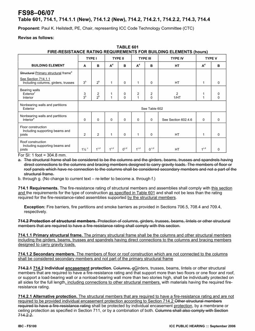
IBC - FS100 ICC PUBLIC HEARING ::: September 2006
FS98–06/07 Table 601, 714.1, 714.1.1 (New), 714.1.2 (New), 714.2, 714.2.1, 714.2.2, 714.3, 714.4 Proponent: Paul K. Heilstedt, PE, Chair, representing ICC Code Technology Committee (CTC) Revise as follows:
TABLE 601 FIRE-RESISTANCE RATING REQUIREMENTS FOR BUILDING ELEMENTS (hours)
TYPE I TYPE II TYPE III TYPE IV TYPE V
BUILDING ELEMENT A B Ad B Ad B HT Ad B
Structural Primary structural framea
See Section 714.1.1 Including columns, girders, trusses 3b 2b 1 0 1 0 HT 1 0
Bearing walls Exteriorf Interior
3 3b
2 2b
1 1
0 0
2 1
2 0
2 1/HT
1 1
0 0
Nonbearing walls and partitions Exterior See Table 602
Nonbearing walls and partitions Interiore 0 0 0 0 0 0 See Section 602.4.6 0 0
Floor construction Including supporting beams and joists 2 2 1 0 1 0 HT 1 0
Roof construction Including supporting beams and joists 1½ c 1c,d 1c,d 0c,d 1c,d 0 c,d HT 1c,d 0
For SI: 1 foot = 304.8 mm. a. The structural frame shall be considered to be the columns and the girders, beams, trusses and spandrels having
direct connections to the columns and bracing members designed to carry gravity loads. The members of floor or roof panels which have no connection to the columns shall be considered secondary members and not a part of the structural frame.
b. through g. (No change to current text – re-letter to become a. through f.) 714.1 Requirements. The fire-resistance rating of structural members and assemblies shall comply with this section and the requirements for the type of construction as specified in Table 601 and shall not be less than the rating required for the fire-resistance-rated assemblies supported by the structural members.
Exception: Fire barriers, fire partitions and smoke barriers as provided in Sections 706.5, 708.4 and 709.4, respectively.
714.2 Protection of structural members. Protection of columns, girders, trusses, beams, lintels or other structural members that are required to have a fire-resistance rating shall comply with this section. 714.1.1 Primary structural frame. The primary structural frame shall be the columns and other structural members including the girders, beams, trusses and spandrels having direct connections to the columns and bracing members designed to carry gravity loads. 714.1.2 Secondary members. The members of floor or roof construction which are not connected to the columns shall be considered secondary members and not part of the primary structural frame 714.2.1 714.2 Individual encasement protection. Columns, gGirders, trusses, beams, lintels or other structural members that are required to have a fire-resistance rating and that support more than two floors or one floor and roof, or support a load-bearing wall or a nonload-bearing wall more than two stories high, shall be individually protected on all sides for the full length, including connections to other structural members, with materials having the required fire-resistance rating. 714.2.1 Alternative protection. The structural members that are required to have a fire-resistance rating and are not required to be provided individual encasement protection according to Section 714.2 Other structural members required to have a fire-resistance rating shall be protected by individual encasement protection, by a membrane or ceiling protection as specified in Section 711, or by a combination of both. Columns shall also comply with Section 714.2.2.
ICC PUBLIC HEARING ::: September 2006 IBC - FS101
714.2.1.1 714.3 Membrane protection. King studs and boundary elements that are integral elements in load-bearing walls of light-framed construction shall be permitted to have required fire-resistance ratings provided by the membrane protection provided for the load-bearing wall. 714.2.2 714.4 Column protection above ceilings. Where columns are required a to be fire-resistance rating rated, the entire column, including its connections to beams or girders, shall be protected provided individual encasement protection on all sides for the full column length. Where the column extends through a ceiling, the fire resistance rating of the column shall be continuous from the top of the foundation or floor/ceiling assembly below through the ceiling space to the top of the column. Reason: The ICC Board established the ICC Code Technology Committee (CTC) as the venue to discuss contemporary code issues in a committee setting which provides the necessary time and flexibility to allow for full participation and input by any interested party. The code issues are assigned to the CTC by the ICC Board as “areas of study”. Information on the CTC, including: meeting agendas; minutes; reports; resource documents; presentations; and all other materials developed in conjunction with the CTC effort can be downloaded from the following website: http://www.iccsafe.org/cs/cc/ctc/index.html Since its inception, the CTC has held six meetings - all open to the public. This proposed change is a result of the CTC’s investigation of the area of study entitled “Review of NIST WTC Recommendations”. The scope of the activity is noted as:
Review the recommendations issued by NIST in its report entitled “Final Report on the Collapse of the World Trade Center Towers”, issued September 2005, for applicability to the building environment as regulated by the I-Codes.
This proposal is intended to address NIST recommendation 7. For this specific proposed change, CTC is working in cooperation with the NIBS/MMC Committee to Translate the NIST World Trade Center Investigation Recommendations for the Model Codes. The CTC notes in their investigation that many of the recommendations contained in the NIST report require additional information for the CTC to further investigate. As such, CTC intends to continue to study the other NIST recommendations. NIST Recommendation #7 is summarized as “NIST recommends the adoption and use of the structural frame approach to fire resistance ratings.” While the IBC currently contains this approach, the NIST team recommends that the concept be reinforced by incorporating text similar to that contained in Footnote a to Table 601 into the pertinent code text for a higher visibility and understanding by code users.
The proposed modification to line 1, column 1 of Table 601 is not intended to revise the intent but to incorporate the revised term. In lieu of a footnote, reliance on the reference to the specific code text of Section 714.1.1 enables a better understanding of the requirements for the pertinent building elements. The modifications to the subsections of Section 714 are intended to retain the current intent. The assemblies for floors and roofs are not consistently referred to as “panels” and the apparent intent is to deal with “floor and roof construction”. The modifications to the several subsections of Section 714 are intended to work in concert with the reference from Table 601 and consolidate text into a more efficient format without a change in intent.
714.1 – The section is revised by incorporating the requirement that the fire-resistance rating of structural members is to comply with “this section” and “Table 601”.
714.1.1 – Existing section 714.2 is not necessary and contains no particular requirements which are not contained in Section 714.1. The text of Section 714.1.1 was revised to more closely resemble the current terminology in line 1 and footnote a of Table 601 which is “structural frame”. The incorporation of “other structural members” in Section 714.1.1 is to place reliance on the function of the member to determine its inclusion in the primary structural frame although a laundry list of commonly understood members is retained for understanding of the intent. The structural members named in the existing laundry list are included in the subsections which apply to such members. It should be noted that this section, as does the current footnote, does not consider the lateral load resisting system as part of the structural frame within the context of fire resistance ratings.
714.1.2 – This text is based on the second sentence of existing Footnote a to Table 601. 714.2 – The proposal utilizes the text and concept contained in existing Section 714.2.1. The inclusion of “encasement” in the section title is to
enhance the focus of the section’s intent. The proposed deletion of “columns” from the laundry list is to eliminate the implication that columns are not required to be individually protected to their full height when protected by Section 711 - Horizontal Assemblies. Individual protection for columns is required by existing Section 714.2.2. This is addressed in proposed Section 714.4. The connections of these elements to other structural members are required to be protected for the continuity of protection.
714.2.1 – The proposal is based on the text in the second sentence of the existing Section 714.2.1 and is addressing those structural members which are not required to be individually protected according to proposed Section 714.2. The last sentence of existing Section 714.2.1 is not needed as proposed Section 714.4 exclusively deals with columns.
714.2.2 – The proposal requires columns to be individually protected for the full column length and columns are not permitted to be protected by membrane protection. Bibliography: Interim Report No. 1 of the CTC, Area of Study – Review of NIST WTC Recommendations, March 9, 2006. National Institute of Standards and Technology. Final Report of the National Construction Safety Team on the Collapses of the World Trade Center Towers. United States Government Printing Office: Washington, D.C. September 2005. Cost Impact: The code change proposal will not increase the cost of construction. Public Hearing: Committee: AS AM D Assembly: ASF AMF DF
FS99–06/07 714.5 Proponent: Susan Lamont, PhD, Arup Fire Revise as follows: 714.5 Exterior structural members. Load-bearing structural members located within the exterior walls or on the outside of a building or structure shall be provided with the highest fire-resistance rating as determined in accordance with the following:
IBC - FS102 ICC PUBLIC HEARING ::: September 2006
1. As required by Table 601 for the type of building element based on the type of construction of the building; 2. As required by Table 601 for exterior bearing walls based on the type of construction; and 3. As required by Table 602 for exterior walls based on the fire separation distance. 4. Where the external fire exposure to structural members located outside of a building can be shown to be less
than the standard fire exposure and stability of the structure is maintained for the duration of the design basis fire then a reduced fire resistance rating may be proposed for approval by the building official.
Reason: The purpose of the code change proposed is to include new text such that performance based design of external structural steel members in response to credible design basis fires in place of the traditional standard fire, can be proposed on projects.
For external steel members the code change would allow engineers to consider the behavior of the steel elements when exposed to external flaming from a credible worst case design fire which in many cases has been shown to be less severe than the fire exposure inside an enclosure or compartment and therefore also less severe than the standard fire.
In general this approach would allow the level of passive fire protection applied to external steel members to be calculated based on the expected fire scenario which could be more or less severe than the standard fire exposure.
Passive fire protection is not always easy to apply or maintain in an external environment. It can also be ineffective when applied to structural steel members such as rods or cables. This code change provides engineers with an alternative approach allowing greater innovation in design. Architects would gain increased freedom to use unprotected steel members on the outside of buildings or structures for aesthetic reasons.
Construction costs may be reduced where passive fire protection is removed or reduced. This proposal will allow a performance based approach and alternative solutions on a case by case basis whilst ensuring building officials can
approve each project on its own merits. Exposure of external steel members to fire has been recognized as a special fire exposure case for many years. Law and O’Brien developed a
methodology to assess the temperature of external steel members exposed to flaming and radiation through openings from post-flashover compartment fires in the 1980s. This has been accepted as performance based design guidance all over the world including the UK, Europe and the US. Bibliography: Law M. and O’Brien T. Fire sand steel construction: Fire safety of bare external structural steel. The Steel Construction Institute, Ascot, Berks, 1981. BS EN 1991-1-2:2002 Eurocode 1: Actions on structures — Part 1-2: General actions — Actions on structures exposed to fire, British Standards Institution. Cost Impact: The code change proposal will not increase the cost of construction. Public Hearing: Committee: AS AM D Assembly: ASF AMF DF
FS100–06/07 714.8 (New), 714.8.1 (New), 714.8.2 (New), 714.8.3 (New), 714.8.3.1 (New, 714.8.3.2 (New), 714.8.4 (New), 714.8.5 (New) Proponent: William M. Connolly, State of New Jersey, Department of Community Affairs, Division of Codes and Standards, representing International Code Council Ad Hoc Committee on Terrorism Resistant Buildings Add new text as follows: 714.8 Spray-Applied Fire Resistive Materials (SFRM). Spray-applied fire resistive materials shall comply with the 714.8.1 through 714.8.4. 714.8.1 Fire Resistance Rating. The application of SFRM shall be consistent with its fire resistance rating listing including, but not limited to, minimum thickness and dry density of the applied SFRM, method of application, substrate surface conditions, the use of bonding adhesives, sealants and reinforcing or other materials. 714.8.2 Manufacturer's Installation Instruction. The application of SFRM shall be in accordance with the manufacturer’s installation instruction. The instructions shall include, but are not limited to, substrate temperatures and surface conditions, and SFRM handling, storage, mixing, conveyance, method of application, curing and ventilation. 714.8.3 Substrate condition. The SFRM shall be applied to a substrate in compliance with 714.8.3.1 through 714.8.3.2. 714.8.3.1 Surface Conditions. Substrates to receive SFRM shall be free of dirt, oil, grease, release agents, loose scale or paint, primers, paints and encapsulants other than those fire-tested and classified by a recognized testing agency, and any other condition that may prevent adequate adhesion. Primed, painted or encapsulated steel shall be allowed provided that testing has demonstrated that required adhesion is maintained. 714.8.3.2 Primers, Paints and Encapsulants. Where the SFRM is to be applied over primers, paints, or encapsulants other than those specified in the listing, the material shall be field tested in accordance with ASTM E 736. Where testing demonstrates that required adhesion is maintained, SFRM shall be permitted to be applied to primed, painted or encapsulated wide flange steel shapes in accordance with the following conditions:
ICC PUBLIC HEARING ::: September 2006 IBC - FS103
1. The beam flange width does not exceed 12 in. (300 mm); or 2. The column flange width does not exceed 16 in. (400 mm); or 3. The beam or column web depth does not exceed 16 in. (400 mm).
4. The average and minimum bond strength values shall be determined based on a minimum of five bond tests conducted in accordance with ASTM E736. Bond tests conducted in accordance with ASTM E 736 indicate a minimum average bond strength of 80 percent and a minimum individual bond strength of 50 percent, when compared to the bond strength of the SFRM as applied to clean uncoated 1/8-in. (3-mm) thick steel plate.
714.8.4 Temperature. A minimum ambient and substrate temperature of 40oF (4.44oC) shall be maintained during and for a minimum of 24 hours after the application of the SFRM, unless the manufacturer’s installation instructions allow otherwise. 714.8.5 Finished condition. The finished condition of SFRM applied to structural members or assemblies shall not, upon complete drying or curing, exhibit cracks, voids, spalls, delamination or any exposure of the substrate. Surface irregularities of spray-applied SFRM shall be deemed acceptable. Reasons: This code change proposal is one of fourteen proposals being submitted by the International Code Council Ad Hoc Committee on Terrorism Resistant Buildings.
The purpose of this proposal is to increase the in-place durability of Spray Applied Fire Resistant Material (SFRM) by established code requirements for the application of the material. The Code currently lacks such provisions. The National Institute of Standards and Technology’s (NIST) investigation of the World Trade Center (WTC) tragedy documented that the proximate cause of the actual collapse was the action of a building contents fire on light steel members in the absence of spray applied fire resistive material, which had been dislodged. Events far less dramatic than an airplane attack have been known to dislodge SFRM. Events as simple as an elevator movement, building sway or maintenance activities can dislodge SFRM if it is not adhered properly. Recommendation 6 of the NIST WTC Report calls for improvement of the in-place durability of SRFM. This proposal is one of three that seeks to achieve that objective. The other two are a proposal for a new Section 403.15 requiring higher bond strengths for SRFM in taller buildings, and a strengthened Section 1704.10 dealing with special inspections of SFRM installations. The proposed new Section 714.8 establishes for the first time in the Code specific requirements governing the application of SFRM.
Sections 714.8.1 and 714.8.2 require that application be in accordance with all terms and conditions of the listing and the manufacturer’s instructions.
Section 714.8.3 deals with the very important issue of substrate. The in-place adhesion of SFRM can be reduced by a factor of 10 when applied over certain primers when compared to the adhesion obtained by the rated material applied on bare clean steel. The section specifies to a field test that must be performed to determine adhesion whenever the field substrate differs from that contemplated by the listing.
Section 714.8.4 specifies a minimum temperature for the application of SFRM. Section 784.8.5 establishes requirements for the finished condition of SFRM. These proposals are based upon existing industry guidelines that are presently being followed by many installers.
Bibliography: Association of the Wall and Ceiling Industries International. Technical Manual 12-A: Standard Practice for the Testing and Inspection of Field Applied Sprayed Fire-resistive Materials; an Annotated Guide. Falls Church, Virginia: Association of the Wall and Ceiling Industries International. 1997, Third Edition. National Institute of Standards and Technology. Final Report of the National Construction Safety Team on the Collapses of the World Trade Center Towers. United States Government Printing Office: Washington, D.C. September 2005. Cost Impact: This proposal will not increase cost since these procedures are already being followed in responsible installations. This code text is needed to ensure that they are always followed. Public Hearing: Committee: AS AM D Assembly: ASF AMF DF FS101–06/07 715.2 Proponent: William E. Koffel, P.E., Koffel Associates, Inc., representing Fire Rated Glazing Industry Revise as follows: 715.2 Fire-resistance-rated glazing. Labeled f Fire-resistance-rated glazing tested as part of a fire-resistance-rated wall assembly in accordance with ASTM E 119 and labeled in accordance with Section 706.2.1 shall be permitted in fire doors and fire window assemblies in accordance with their listings and shall not otherwise be required to comply with this section. Reason: Currently the Code exempts fire resistance rated glazing from the requirements of Section 715 because such glazing should not be considered an opening since it has been tested and meets the performance requirements for a fire resistance rated wall assembly. However, the current Code provisions do not clearly indicate that such glazing should be permitted to be used wherever fire protection rated glazing is permitted. The purpose of this proposal is to make clear how fire resistance rated glazing used in fire doors and fire window assemblies should be labeled. Confusion could exist as to whether it should be labeled with a “W” in accordance with 706.2.1, or a “D” in accordance with 715.4.6.3.1, or an “OH” in accordance with 715.5.8.1. The proposed revision makes it clear that fire resistance rated glazing is to be labeled “W” wherever it is used, including fire doors and fire window assemblies. Cost Impact: The code change proposal will not increase the cost of construction. Public Hearing: Committee: AS AM D Assembly: ASF AMF DF
IBC - FS104 ICC PUBLIC HEARING ::: September 2006
FS102–06/07 715.3, 715.4.3.2, 715.5, 715.5.1, 715.5.2, 715.5.8.1, Chapter 35 (New) Proponent: Bob Eugene/ Underwriters Laboratories Inc. 1. Revise as follows: 715.3 Alternative methods for determining fire protection ratings. The application of any of the alternative methods listed in this section shall be based on the fire exposure and acceptance criteria specified in NFPA 252, or NFPA 257 or UL 9. The required fire resistance of an opening protective shall be permitted to be established by any of the following methods or procedures:
1. Designs documented in approved sources. 2. Calculations performed in an approved manner. 3. Engineering analysis based on a comparison of opening protective designs having fire-protection ratings as
determined by the test procedures set forth in NFPA 252, or NFPA 257 or UL 9. 4. Alternative protection methods as allowed by Section 104.11.
715.4.3.2 Glazing in door assemblies. In a 20-minute fire door assembly, the glazing material in the door itself shall have a minimum fire-protection rating of 20 minutes and shall be exempt from the hose stream test. Glazing material in any other part of the door assembly, including transom lites and sidelites, shall be tested in accordance with NFPA 257 or UL 9, including the hose stream test, in accordance with Section 715.5. 715.5 Fire-protection-rated glazing. Glazing in fire window assemblies shall be fire-protection rated in accordance with this section and Table 715.5. Glazing in fire door assemblies shall comply with Section 715.4.6. Fire-protection-rated glazing shall be tested in accordance with and shall meet the acceptance criteria of NFPA 257 or UL 9. Fire-protection-rated glazing shall also comply with NFPA 80. Openings in nonfire-resistance-rated exterior wall assemblies that require protection in accordance with Section 704.3, 704.8, 704.9 or 704.10 shall have a fire-protection rating of not less than 3/4 hour.
Exceptions:
1. Wired glass in accordance with Section 715.5.3. 2. Fire-protection-rated glazing in 0.5-hour fire-resistance-rated partitions is permitted to have an 0.33-hour fire-
protection rating. 715.5.1 Testing under positive pressure. NFPA 257 or UL 9 shall evaluate fire-protection-rated glazing under positive pressure. Within the first 10 minutes of a test, the pressure in the furnace shall be adjusted so at least two-thirds of the test specimen is above the neutral pressure plane, and the neutral pressure plane shall be maintained at that height for the balance of the test. 715.5.2 Nonsymmetrical glazing systems. Nonsymmetrical fire-protection-rated glazing systems in fire partitions, fire barriers or in exterior walls with a fire separation distance of 5 feet (1524 mm) or less pursuant to Section 704 shall be tested with both faces exposed to the furnace, and the assigned fire protection rating shall be the shortest duration obtained from the two tests conducted in compliance with NFPA 257 or UL 9. 715.5.8.1 Identification. For fire-protection-rated glazing, the label shall bear the following two-part identification: “OH – XXX.” “OH” indicates that the glazing meets both the fire-resistance and the hose-stream requirements of NFPA 257 or UL 9 and is permitted to be used in openings. “XXX” represents the fire-protection rating period, in minutes, that was tested. 2. Add standard to Chapter 35 as follows:
UL 9-2000 Fire Tests of Window Assemblies, with Revisions through April 2005 Reason: The purpose of this code change is to include reference to UL 9 as an alternate to NFPA 257 which is currently referenced in these code sections. These two Standards describe the same test method. The specifications for the test apparatus and test procedure are identical between the two standards. As such, identical test results would be obtained from tests conducted using each of these methods.
UL 9 is an ANSI approved standard. The inclusion of this alternate test method would provide the authority having jurisdiction with the flexibility to accept listed and labeled products evaluated in accordance with NFPA 257 or UL 9. Cost Impact: The code change proposal will not increase cost of construction. Analysis: Results of the review of the proposed standard(s) will be posted on the ICC website by August 20, 2006. Public Hearing: Committee AS AM D Assembly: ASF AMF DF