03-018v3
246
Copies of this document may be purchased from: NCITS xxx-xxxx Global Engineering, 15 Inverness Way East, T11/Project 1508-D/Rev 6.5 Englewood, CO 80112-5704 Phone: (800) 854-7179 or (303) 792-2181 Fax: (303) 792-2192 FIBRE CHANNEL SWITCH FABRIC - 3 (FC-SW-3) REV 6.5 NCITS working draft proposed American National Standard for Information Technology October 31, 2003 Secretariat: Information Technology Industry Council NOTE: This is a working draft American National Standard of Accredited Standards Committee NCITS. As such this is not a completed standard. The T11 Technical Committee or anyone else may modify this document as a result of comments received anytime, or during a future public review and its eventual approval as a Standard. Use of the information contained herein is at your own risk. Permission is granted to members of NCITS, its technical committees, and their associated task groups to reproduce this document for the purposes of NCITS standardization activities without further permission, provided this notice is included. All other rights are reserved. Any duplication of this document for commercial or for-profit use is strictly prohibited. POINTS OF CONTACT: Robert Snively (T11 Chairman) Brocade Communications Systems, Inc. 1745 Technology Drive San Jose, CA 95110 (408) 487-8135 Fax: (408) 392-6655 E-mail: [email protected] Ed McGlaughlin (FC-SW-3 Facilitator) Qlogic Corporation 6321 Bury Drive Eden Prairie, MN 55346 (952) 932-4085 Fax: (952) 932-4037 E-Mail: [email protected] Ed Grivna (T11 Vice Chairman) Cypress Semiconductor 2401 East 86th Street Bloomington, MN 55425 (952) 851-5046 Fax: (952) 851-5087 E-Mail: [email protected] Steven Wilson (FC-SW-3 Technical Editor) Brocade Communications Systems, Inc. 1745 Technology Drive San Jose, CA 95110 (408) 487-8128 Fax: (408) 392-6655 E-mail: [email protected]
description
FC-3 NCITS
Transcript of 03-018v3

Copies of this document may be purchased from: NCITS xxx-xxxxGlobal Engineering, 15 Inverness Way East, T11/Project 1508-D/Rev 6.5Englewood, CO 80112-5704Phone: (800) 854-7179 or (303) 792-2181 Fax: (303) 792-2192
FIBRE CHANNELSWITCH FABRIC - 3
(FC-SW-3)
REV 6.5
NCITS working draft proposedAmerican National Standardfor Information Technology
October 31, 2003
Secretariat: Information Technology Industry Council
NOTE:This is a working draft American National Standard of Accredited Standards Committee NCITS. Assuch this is not a completed standard. The T11 Technical Committee or anyone else may modifythis document as a result of comments received anytime, or during a future public review and itseventual approval as a Standard. Use of the information contained herein is at your own risk.
Permission is granted to members of NCITS, its technical committees, and their associated taskgroups to reproduce this document for the purposes of NCITS standardization activities withoutfurther permission, provided this notice is included. All other rights are reserved. Any duplicationof this document for commercial or for-profit use is strictly prohibited.
POINTS OF CONTACT:
Robert Snively (T11 Chairman)Brocade Communications Systems, Inc.1745 Technology DriveSan Jose, CA 95110(408) 487-8135Fax: (408) 392-6655E-mail: [email protected]
Ed McGlaughlin (FC-SW-3 Facilitator)Qlogic Corporation6321 Bury DriveEden Prairie, MN 55346(952) 932-4085Fax: (952) 932-4037E-Mail: [email protected]
Ed Grivna (T11 Vice Chairman)Cypress Semiconductor2401 East 86th StreetBloomington, MN 55425(952) 851-5046Fax: (952) 851-5087E-Mail: [email protected]
Steven Wilson (FC-SW-3 Technical Editor)Brocade Communications Systems, Inc.1745 Technology DriveSan Jose, CA 95110(408) 487-8128Fax: (408) 392-6655E-mail: [email protected]

ii

Editor’s Notes, revision 6.5:
Addressed comments according to 03-110vB + 03-649v0.
Editor’s Notes, revision 6.4:
Addressed comments according to 03-110vA.
Editor’s Notes, revision 6.3:
Completed removal of FC-FG references (02-751v0).
ISO Editorial Changes
Removal of LOOPD
Synched Up dNS and dMS Command Tables with FC-GS-4
Editor’s Notes, revision 6.2:
Changed references from FC-PH to FC-FS.
Partially removed references to FG-FG (02-751v0).
Updated Annex A. 02-257v0
Included Hard Zoning proposal 02-508v2
Included Get Port Speed Capabilities 02-319v0
Included ISL BB Credit Recovery 02-221v1
FSPF Fix 02-601v2
Aligned SFC Command Codes with FC-SP 02-341v1
Included SW_RSCN Fix 02-736v0
Included new dNS rule 02-711v0
Included updated Zone Merge examples 02-725v0
Included fix for Domain ID Assignment 02-682v0
Included new SW_RJT Command codes for ACA, SFC, UFC, and RCA. Deleted failure codes fromthe Zoning Accept structures 02-606v2.
Included updated Switch Port Initialization State Machine 02-446v0
Removed annotations from the state diagrams
Editor’s Notes, revision 6.1:
Updated ILS Command Table for Security and FC-BB-2
Included CSWR ILS 01-609v1
Included ESS 02-402v1
Included Fabric Initialization Clarifications 02-457v0
Included BF Clarifications 02-455v2
Included RCF Clarifications 02-032v4
Included Inter-Switch FDMI
Included Clauses from the Unified Zoning Document 02-191v3
Included Distributed Broadcast proposal

Included Broadcast Zone proposal 02-460v0
Included MRRA SLW_ILS
Editor’s Notes, revision 6.01:
Updated ILS Command Code Table
Reserved SFC commands for Security
Included 02-079v2
Editor’s Notes, revision 6.0:
Initial FC-SW-3 Draft. Moved Zoning ILS’s to Clause 6. Included accepted proposals through Decem-ber 2001:
00-004v0 Twice is a charm!
01-247v0
01-503v2; Except: FSPF and Distributed Server Modifications
01-506v0
01-614v1
01-659v0; FC-SW-3 Portion

v
ANSI ®NCITS xxx-xxxx
draft proposed American National Standardfor Information Technology
Fibre Channel —Switch Fabric - 3 (FC-SW-3)
Secretariat
Information Technology Industry Council
Approved ,200x
American National Standards Institute, Inc.
Abstract
This standard describes the requirements for an interconnecting Fabric consisting of multiple FabricSwitch elements to support the ANSI/INCITS Fibre Channel - Framing and Signaling (FC-FS) and AN-SI/INCITS Fibre Channel - Physical Interface (FC-PI) standards.

vi
American National Standard
Approval of an American National Standard requires verification by ANSI that the requirements for dueprocess, consensus, and other criteria for approval have been met by the standards developer.
Consensus is established when, in the judgement of the ANSI Board of Standards Review, substantialagreement has been reached by directly and materially affected interests. Substantial agreementmeans much more than a simple majority, but not necessarily unanimity. Consensus requires that allviews and objections be considered, and that a concerted effort be made towards their resolution.
The use of American National Standards is completely voluntary; their existence does not in anyrespect preclude anyone, whether he has approved the standards or not, from manufacturing,marketing, purchasing, or using products, processes, or procedures not conforming to the standards.
The American National Standards Institute does not develop standards and in no circumstances giveinterpretation on any American National Standard. Moreover, no person shall have the right orauthority to issue an interpretation of an American National Standard in the name of the AmericanNational Standards Institute. Requests for interpretations should be addressed to the secretariat orsponsor whose name appears on the title page of this standard.
CAUTION NOTICE: This American National Standard may be revised or withdrawn at any time. Theprocedures of the American National Standards Institute require that action be taken periodically toreaffirm, revise, or withdraw this standard. Purchasers of American National Standards may receivecurrent information on all standards by calling or writing the American National Standards Institute.
The developers of this Standard have requested that holder's of patents that may be required for theimplementation of the Standard, disclose such patents to the publisher. However, neither thedevelopers nor the publisher have undertaken a patent search in order to identify which, if any, patentsmay apply to this Standard.
PATENTSTATEMENT
As of the date of publication of this standard, following calls for the identification of patents that maybe required for the implementation of the standard, notice of one or more such claims has been re-ceived. No further patent search is conducted by the developer or the publisher in respect to anyStandard it processes. No representation is made or implied that licenses are not required to avoidinfringement in the use of this Standard.
Published by
American National Standards Institute11 W. 42nd Street, New York, New York 10036
Copyright © 200x by American National Standards InstituteAll rights reserved
No part of this publication may be reproduced in anyform, in an electronic retrieval system or otherwise,without prior written permission of the publisher.
Printed in the United States of America

Foreword (This Foreword is not part of American National Standard NCITS xxx-xxx.)
This standard describes the requirements for an interconnecting Fabric consisting of multiple FabricSwitch elements to support the ANSI/INCITS Fibre Channel - Framing and Signaling (FC-FS) andANSI/INCITS Fibre Channel - Physical Interface (FC-PI) standards.
This standard was developed by Task Group T11 of Accredited Standards Committee NCITS during2001-2003. The standards approval process started in 2003. This document includes annexes thatare informative and are not considered part of the standard.
Requests for interpretation, suggestions for improvements or addenda, or defect reports are wel-come. They should be sent to the NCITS Secretariat, Information Technology Industry Council, 1250Eye Street, NW, Suite 200, Washington, DC 20005-3922.
This standard was processed and approved for submittal to ANSI by the National Committee for In-formation Technology Standards (NCITS). Committee approval of the standard does not necessarilyimply that all committee members voted for approval. At the time it approved this standard, NCITShad the following members:
(to be filled in by NCITS)
vii

Technical Committee T11 on Lower Level Interfaces, which reviewed this standard, had the followingmembers:
Robert Snively, ChairEdward Grivna, Vice-ChairNeil Wanamaker, Secretary
Company Name
TBD.
IntroductionFC-SW-3 is one of the Fibre Channel family of standards. This family includes INCITS/ANSI FC-FSand INCITS/ANSI FC-PI. INCITS/ANSI FC-GS-4, is a document related to Generic Fabric Servicesand is closely tied to FC-SW-3. ANSI/INCITS FC-BB-2 describes how Fabrics are extended overtransports complementary to Fibre Channel. ANSI/INCITS FC-MI-2 and ANSI/INCITS FC-DA de-scribe interoperability profiles that assists in the interoperability of Switches. INCITS 332: 1999, FC-AL-2, specifies the arbitrated loop topology. ANSI/INCITS FC-SP describes the Security require-ments and protocols associated with Fibre Channel networks.
FC-SW-3 describes how switches communicate and interact with one another to form a Fabric ofswitches. Included are Fabric initialization and configuration, routing, server communication, eventdistribution and repository exchanges (e.g., zoning information).
Acknowledgements
The technical editor would like to thank the following individuals for their special contributions to this-standard:
Charles Binford
Craig Carlson
Claudio Desanti
Ken Hirata
Larry Hofer
Scott Kipp
Jim Kleinsteiber
Greg Koellner
Kumar Malavalli
Bill Martin
Michael O’Donnell
Harry Paul
David Peterson
Robert Snively
Ralph Weber
Steve Wilson
viii

Contents Page
1 Scope . . . . . . . . . . . . . . . . . . . . . . . . . . . . . . . . . . . . . . . 1
2 Normative references . . . . . . . . . . . . . . . . . . . . . . . . . . . . . . . 12.1 Approved references . . . . . . . . . . . . . . . . . . . . . . . . . . . . . . . . . . . . . . . . . . . 12.2 References under development . . . . . . . . . . . . . . . . . . . . . . . . . . . . . . . . . . . 2
3 Definitions and conventions . . . . . . . . . . . . . . . . . . . . . . . . . . . . 33.1 Definitions . . . . . . . . . . . . . . . . . . . . . . . . . . . . . . . . . . . . . . . . . . . . . . . . . . . 33.2 Editorial conventions . . . . . . . . . . . . . . . . . . . . . . . . . . . . . . . . . . . . . . . . . . . 73.3 State Machine notation . . . . . . . . . . . . . . . . . . . . . . . . . . . . . . . . . . . . . . . . . 93.4 Abbreviations, acronyms, and symbols . . . . . . . . . . . . . . . . . . . . . . . . . . . . . 93.5 Definition of Compliance Terms . . . . . . . . . . . . . . . . . . . . . . . . . . . . . . . . . . 103.6 Keywords . . . . . . . . . . . . . . . . . . . . . . . . . . . . . . . . . . . . . . . . . . . . . . . . . . 11
4 Structure and Concepts . . . . . . . . . . . . . . . . . . . . . . . . . . . . . . 124.1 Overview . . . . . . . . . . . . . . . . . . . . . . . . . . . . . . . . . . . . . . . . . . . . . . . . . . . 124.2 E_Port Operation . . . . . . . . . . . . . . . . . . . . . . . . . . . . . . . . . . . . . . . . . . . . 124.3 Fabric Operation . . . . . . . . . . . . . . . . . . . . . . . . . . . . . . . . . . . . . . . . . . . . . 124.4 Fabric Definition . . . . . . . . . . . . . . . . . . . . . . . . . . . . . . . . . . . . . . . . . . . . . 134.5 Switch . . . . . . . . . . . . . . . . . . . . . . . . . . . . . . . . . . . . . . . . . . . . . . . . . . . . . 134.6 Switching characteristics . . . . . . . . . . . . . . . . . . . . . . . . . . . . . . . . . . . . . . . 15
4.6.1 Switching overview . . . . . . . . . . . . . . . . . . . . . . . . . . . . . . . . . . . . . . . . 154.6.2 Synchronous switching . . . . . . . . . . . . . . . . . . . . . . . . . . . . . . . . . . . . . 154.6.3 Asynchronous switching . . . . . . . . . . . . . . . . . . . . . . . . . . . . . . . . . . . . 15
4.7 Switch Ports and Bridge Ports . . . . . . . . . . . . . . . . . . . . . . . . . . . . . . . . . . . 164.7.1 General Characteristics . . . . . . . . . . . . . . . . . . . . . . . . . . . . . . . . . . . . . 164.7.2 F_Port . . . . . . . . . . . . . . . . . . . . . . . . . . . . . . . . . . . . . . . . . . . . . . . . . 164.7.3 FL_Port . . . . . . . . . . . . . . . . . . . . . . . . . . . . . . . . . . . . . . . . . . . . . . . . 164.7.4 E_Port . . . . . . . . . . . . . . . . . . . . . . . . . . . . . . . . . . . . . . . . . . . . . . . . . 164.7.4 B_Port . . . . . . . . . . . . . . . . . . . . . . . . . . . . . . . . . . . . . . . . . . . . . . . . . 174.7.5 G_Ports and GL_Ports . . . . . . . . . . . . . . . . . . . . . . . . . . . . . . . . . . . . . 17
4.8 Fabric Addressing . . . . . . . . . . . . . . . . . . . . . . . . . . . . . . . . . . . . . . . . . . . . 174.9 Class F Service . . . . . . . . . . . . . . . . . . . . . . . . . . . . . . . . . . . . . . . . . . . . . . 194.10 FSPF-Backbone Fabric . . . . . . . . . . . . . . . . . . . . . . . . . . . . . . . . . . . . . . . 19
5 Switch Ports and Bridge Ports . . . . . . . . . . . . . . . . . . . . . . . . . . . 205.1 Overview . . . . . . . . . . . . . . . . . . . . . . . . . . . . . . . . . . . . . . . . . . . . . . . . . . . 205.2 Model elements . . . . . . . . . . . . . . . . . . . . . . . . . . . . . . . . . . . . . . . . . . . . . . 20
5.2.1 FC Transports . . . . . . . . . . . . . . . . . . . . . . . . . . . . . . . . . . . . . . . . . . . . 205.2.2 Switch Transport . . . . . . . . . . . . . . . . . . . . . . . . . . . . . . . . . . . . . . . . . . 205.2.3 Control Facilities . . . . . . . . . . . . . . . . . . . . . . . . . . . . . . . . . . . . . . . . . . 205.2.4 Link Services . . . . . . . . . . . . . . . . . . . . . . . . . . . . . . . . . . . . . . . . . . . . 21
5.3 F_Port Operation . . . . . . . . . . . . . . . . . . . . . . . . . . . . . . . . . . . . . . . . . . . . . 215.4 FL_Port Operation . . . . . . . . . . . . . . . . . . . . . . . . . . . . . . . . . . . . . . . . . . . . 225.5 E_Port Operation . . . . . . . . . . . . . . . . . . . . . . . . . . . . . . . . . . . . . . . . . . . . 235.6 B_Port Operation . . . . . . . . . . . . . . . . . . . . . . . . . . . . . . . . . . . . . . . . . . . . 255.7 Inter-Switch Link Behavior . . . . . . . . . . . . . . . . . . . . . . . . . . . . . . . . . . . . . . 265.8 Class F Service . . . . . . . . . . . . . . . . . . . . . . . . . . . . . . . . . . . . . . . . . . . . . . 27
5.8.1 Class F Function . . . . . . . . . . . . . . . . . . . . . . . . . . . . . . . . . . . . . . . . . . 275.8.2 Class F Rules . . . . . . . . . . . . . . . . . . . . . . . . . . . . . . . . . . . . . . . . . . . . 27
ix

Page5.8.3 Class F Frame Format . . . . . . . . . . . . . . . . . . . . . . . . . . . . . . . . . . . . . . 295.8.4 Class F Flow Control . . . . . . . . . . . . . . . . . . . . . . . . . . . . . . . . . . . . . . . 30
6 Internal Link Services . . . . . . . . . . . . . . . . . . . . . . . . . . . . . . 316.1 Switch Fabric Internal Link Services (SW_ILS) . . . . . . . . . . . . . . . . . . . . . . . 31
6.1.1 SW_ILS Overview . . . . . . . . . . . . . . . . . . . . . . . . . . . . . . . . . . . . . . . . . 316.1.2 Switch Fabric Internal Link Service Accept (SW_ACC) . . . . . . . . . . . . . . 326.1.3 Switch Fabric Internal Link Service Reject (SW_RJT) . . . . . . . . . . . . . . . 336.1.4 Exchange Link Parameters (ELP) . . . . . . . . . . . . . . . . . . . . . . . . . . . . . 366.1.5 Exchange Fabric Parameters (EFP) . . . . . . . . . . . . . . . . . . . . . . . . . . . . 436.1.6 Domain Identifier Assigned (DIA) . . . . . . . . . . . . . . . . . . . . . . . . . . . . . . 476.1.7 Request Domain_ID (RDI) . . . . . . . . . . . . . . . . . . . . . . . . . . . . . . . . . . . 486.1.8 Hello (HLO) . . . . . . . . . . . . . . . . . . . . . . . . . . . . . . . . . . . . . . . . . . . . . . 51
6.1.8.1 HLO Overview . . . . . . . . . . . . . . . . . . . . . . . . . . . . . . . . . . . . . . . . . 516.1.8.2 FSPF Header Format . . . . . . . . . . . . . . . . . . . . . . . . . . . . . . . . . . . 52
6.1.9 Link State Update (LSU) . . . . . . . . . . . . . . . . . . . . . . . . . . . . . . . . . . . . 536.1.9.1 LSU Overview . . . . . . . . . . . . . . . . . . . . . . . . . . . . . . . . . . . . . . . . . 536.1.9.2 Link-State Record (LSR) Format . . . . . . . . . . . . . . . . . . . . . . . . . . . 546.1.9.3 Link State Header Format . . . . . . . . . . . . . . . . . . . . . . . . . . . . . . . . 566.1.9.4 Link Descriptor Format . . . . . . . . . . . . . . . . . . . . . . . . . . . . . . . . . . 576.1.9.5 Summary Descriptor Format. . . . . . . . . . . . . . . . . . . . . . . . . . . . . . . 58
6.1.10 Link State Acknowledgement (LSA) . . . . . . . . . . . . . . . . . . . . . . . . . . . 586.1.11 Build Fabric (BF) . . . . . . . . . . . . . . . . . . . . . . . . . . . . . . . . . . . . . . . . . 596.1.12 Reconfigure Fabric (RCF) . . . . . . . . . . . . . . . . . . . . . . . . . . . . . . . . . . 606.1.13 Inter-Switch Registered State Change Notification (SW_RSCN) . . . . . . 616.1.14 Distribute Registered Link Incident Records (DRLIR) . . . . . . . . . . . . . . 646.1.15 Disconnect Class 1 Connection (DSCN) . . . . . . . . . . . . . . . . . . . . . . . 656.1.16 Merge Request (MR) . . . . . . . . . . . . . . . . . . . . . . . . . . . . . . . . . . . . . . 66
6.1.16.1 Merge Request Payload . . . . . . . . . . . . . . . . . . . . . . . . . . . . . . . . 676.1.16.1.1 Merge Request Payload in Basic Zoning . . . . . . . . . . . . . . . . . 686.1.16.1.2 Merge Request Payload in Enhanced Zoning . . . . . . . . . . . . . 69
6.1.16.2 Merge Request Reply . . . . . . . . . . . . . . . . . . . . . . . . . . . . . . . . . . 706.1.17 Acquire Change Authorization Request (ACA) . . . . . . . . . . . . . . . . . . . 706.1.18 Release Change Authorization (RCA) Request . . . . . . . . . . . . . . . . . . 726.1.19 Stage Fabric Configuration Update (SFC) Request . . . . . . . . . . . . . . . 73
6.1.19.1 SFC in Basic Zoning . . . . . . . . . . . . . . . . . . . . . . . . . . . . . . . . . . . 756.1.19.2 SFC in Enhanced Zoning . . . . . . . . . . . . . . . . . . . . . . . . . . . . . . . . 76
6.1.19.2.1 Operation Request ‘Activate Zone Set Enhanced’ . . . . . . . . . . 766.1.19.2.2 Operation Request ‘Deactivate Zone Set Enhanced’ . . . . . . . . 776.1.19.2.3 Operation Request ‘Distribute Zone Set Database’ . . . . . . . . . 776.1.19.2.4 Operation Request ‘Activate Zone Set by Name’ . . . . . . . . . . . 776.1.19.2.5 Operation Request ‘Set Zoning Policies’ . . . . . . . . . . . . . . . . . 78
6.1.20 Update Fabric Configuration (UFC) Request . . . . . . . . . . . . . . . . . . . . 786.1.21 Exchange Switch Capabilities . . . . . . . . . . . . . . . . . . . . . . . . . . . . . . . 796.1.22 Exchange Switch Support (ESS) . . . . . . . . . . . . . . . . . . . . . . . . . . . . . 82
6.1.22.1 ESS Request Payload . . . . . . . . . . . . . . . . . . . . . . . . . . . . . . . . . . 826.1.22.2 Interconnect Element Information Object . . . . . . . . . . . . . . . . . . . . 836.1.22.3 Capability Object . . . . . . . . . . . . . . . . . . . . . . . . . . . . . . . . . . . . . . 836.1.22.4 Service Specific Capability Formats . . . . . . . . . . . . . . . . . . . . . . . . 84
6.1.22.4.1 Directory Server Capability . . . . . . . . . . . . . . . . . . . . . . . . . . . 846.1.22.4.2 Fabric Controller Capability . . . . . . . . . . . . . . . . . . . . . . . . . . . 846.1.22.4.3 ESS Fabric Configuration Server Capability Object . . . . . . . . . 85
x

Page
6.1.22.4.4 ESS Enhanced Zone Server Capability Object . . . . . . . . . . . . 866.1.22.4.5 ESS-Vendor Specific Capability Object . . . . . . . . . . . . . . . . . . 87
6.1.22.5 ESS Accept Payload . . . . . . . . . . . . . . . . . . . . . . . . . . . . . . . . . . . 886.1.23 Merge Request Resource Allocation (MRRA) . . . . . . . . . . . . . . . . . . . 88
7 Fabric Configuration . . . . . . . . . . . . . . . . . . . . . . . . . . . . . . . . 917.1 Fabric Configuration Summary . . . . . . . . . . . . . . . . . . . . . . . . . . . . . . . . . . 917.2 Switch Port Initialization . . . . . . . . . . . . . . . . . . . . . . . . . . . . . . . . . . . . . . . . 91
7.2.1 Basic Operation . . . . . . . . . . . . . . . . . . . . . . . . . . . . . . . . . . . . . . . . . . 917.2.2 Exchange Switch Capabilities Processing . . . . . . . . . . . . . . . . . . . . . . . 99
7.3 Principal Switch Selection . . . . . . . . . . . . . . . . . . . . . . . . . . . . . . . . . . . . . 1007.4 Address Distribution . . . . . . . . . . . . . . . . . . . . . . . . . . . . . . . . . . . . . . . . . 107
7.4.1 Address Distribution Overview . . . . . . . . . . . . . . . . . . . . . . . . . . . . . . . 1077.4.2 Domain_ID Distribution by the Principal Switch . . . . . . . . . . . . . . . . . . 1097.4.3 Domain_ID Requests by the Switches . . . . . . . . . . . . . . . . . . . . . . . . . 111
7.5 E_Port and Fabric Isolation . . . . . . . . . . . . . . . . . . . . . . . . . . . . . . . . . . . . 1147.6 B_Port Operation . . . . . . . . . . . . . . . . . . . . . . . . . . . . . . . . . . . . . . . . . . . 115
7.6.1 Differences Between E_Ports and B_Ports . . . . . . . . . . . . . . . . . . . . . 1157.6.2 B_Port Internal Link Services . . . . . . . . . . . . . . . . . . . . . . . . . . . . . . . 1157.6.3 B_Port Initialization . . . . . . . . . . . . . . . . . . . . . . . . . . . . . . . . . . . . . . . 1167.6.4 Example B_Port Configuration . . . . . . . . . . . . . . . . . . . . . . . . . . . . . . 116
8 Fabric Shortest Path First (FSPF) . . . . . . . . . . . . . . . . . . . . . . . . 1178.1 Overview . . . . . . . . . . . . . . . . . . . . . . . . . . . . . . . . . . . . . . . . . . . . . . . . . . 117
8.1.1 Basic Components . . . . . . . . . . . . . . . . . . . . . . . . . . . . . . . . . . . . . . . 1178.1.2 Fabric connectivity . . . . . . . . . . . . . . . . . . . . . . . . . . . . . . . . . . . . . . . 1178.1.3 Addressing . . . . . . . . . . . . . . . . . . . . . . . . . . . . . . . . . . . . . . . . . . . . . 1178.1.4 Path Selection and Routing . . . . . . . . . . . . . . . . . . . . . . . . . . . . . . . . . 1188.1.5 Hierarchical Path Selection . . . . . . . . . . . . . . . . . . . . . . . . . . . . . . . . . 1188.1.6 FSPF Path Selection Summary . . . . . . . . . . . . . . . . . . . . . . . . . . . . . . 118
8.2 FSPF Message Processing . . . . . . . . . . . . . . . . . . . . . . . . . . . . . . . . . . . . 1188.2.1 Message transmission . . . . . . . . . . . . . . . . . . . . . . . . . . . . . . . . . . . . 1188.2.2 Message Reception and Tests . . . . . . . . . . . . . . . . . . . . . . . . . . . . . . 119
8.3 Hello Protocol . . . . . . . . . . . . . . . . . . . . . . . . . . . . . . . . . . . . . . . . . . . . . . 1198.3.1 Basic Functions . . . . . . . . . . . . . . . . . . . . . . . . . . . . . . . . . . . . . . . . . 1198.3.2 Hello Message Transmission . . . . . . . . . . . . . . . . . . . . . . . . . . . . . . . . 1198.3.3 Hello Message Parameters . . . . . . . . . . . . . . . . . . . . . . . . . . . . . . . . . 1208.3.4 Hello Message Reception . . . . . . . . . . . . . . . . . . . . . . . . . . . . . . . . . . 120
8.4 The Topology Database . . . . . . . . . . . . . . . . . . . . . . . . . . . . . . . . . . . . . . 1218.5 Usage of LSR Fields . . . . . . . . . . . . . . . . . . . . . . . . . . . . . . . . . . . . . . . . . 121
8.5.1 LSR Age . . . . . . . . . . . . . . . . . . . . . . . . . . . . . . . . . . . . . . . . . . . . . . . 1218.5.2 LSR Incarnation Number . . . . . . . . . . . . . . . . . . . . . . . . . . . . . . . . . . . 1228.5.3 LSR Instance Rules . . . . . . . . . . . . . . . . . . . . . . . . . . . . . . . . . . . . . . 1228.5.4 LSR Checksum . . . . . . . . . . . . . . . . . . . . . . . . . . . . . . . . . . . . . . . . . . 1238.5.5 Link Cost . . . . . . . . . . . . . . . . . . . . . . . . . . . . . . . . . . . . . . . . . . . . . . 125
8.6 Topology Database Synchronization . . . . . . . . . . . . . . . . . . . . . . . . . . . . . 1258.6.1 Synchronization Overview . . . . . . . . . . . . . . . . . . . . . . . . . . . . . . . . . . 1258.6.2 Neighborhood and Adjacency . . . . . . . . . . . . . . . . . . . . . . . . . . . . . . . 1268.6.3 Continuous Topology Database Synchronization . . . . . . . . . . . . . . . . . 1278.6.4 Reliable Flooding . . . . . . . . . . . . . . . . . . . . . . . . . . . . . . . . . . . . . . . . 128
8.6.4.1 Basic Operation . . . . . . . . . . . . . . . . . . . . . . . . . . . . . . . . . . . . . . 128
xi
Page8.6.4.2 The Flooding Procedure . . . . . . . . . . . . . . . . . . . . . . . . . . . . . . . . 1288.6.4.3 Generating a New LSR . . . . . . . . . . . . . . . . . . . . . . . . . . . . . . . . . 1288.6.4.4 Transmitting an LSR . . . . . . . . . . . . . . . . . . . . . . . . . . . . . . . . . . . 1298.6.4.5 Receiving an LSR . . . . . . . . . . . . . . . . . . . . . . . . . . . . . . . . . . . . . 129
8.7 Neighbor Finite State Machine (FSM) . . . . . . . . . . . . . . . . . . . . . . . . . . . . . 1308.8 FSPF-Backbone . . . . . . . . . . . . . . . . . . . . . . . . . . . . . . . . . . . . . . . . . . . . 134
8.8.1 FSPF-Backbone Overview . . . . . . . . . . . . . . . . . . . . . . . . . . . . . . . . . . 1348.8.2 Multiple Switch Connections . . . . . . . . . . . . . . . . . . . . . . . . . . . . . . . . 1378.8.3 FSPF-Backbone Point-to-point Links . . . . . . . . . . . . . . . . . . . . . . . . . . 1388.8.4 FSPF-Backbone Routing Protocol . . . . . . . . . . . . . . . . . . . . . . . . . . . . 138
9 Distributed Services . . . . . . . . . . . . . . . . . . . . . . . . . . . . . . . 1409.1 Basic Model . . . . . . . . . . . . . . . . . . . . . . . . . . . . . . . . . . . . . . . . . . . . . . . . 1409.2 Distributed Services Framework . . . . . . . . . . . . . . . . . . . . . . . . . . . . . . . . . 140
9.2.1 Goals and Characteristics of the Distributed Services Framework . . . . . 1409.2.2 Distributed Service Transport . . . . . . . . . . . . . . . . . . . . . . . . . . . . . . . . 140
9.2.2.1 Required FC-2 Parameters . . . . . . . . . . . . . . . . . . . . . . . . . . . . . . 1409.2.2.2 FC-CT Header Usage . . . . . . . . . . . . . . . . . . . . . . . . . . . . . . . . . . 1419.2.2.3 Frame Distribution . . . . . . . . . . . . . . . . . . . . . . . . . . . . . . . . . . . . . 141
9.2.3 Common Characteristics . . . . . . . . . . . . . . . . . . . . . . . . . . . . . . . . . . . 1419.2.4 Zoning Considerations . . . . . . . . . . . . . . . . . . . . . . . . . . . . . . . . . . . . . 1429.2.5 Work Categories . . . . . . . . . . . . . . . . . . . . . . . . . . . . . . . . . . . . . . . . . 1429.2.6 Frame Formats . . . . . . . . . . . . . . . . . . . . . . . . . . . . . . . . . . . . . . . . . . 1439.2.7 FC-CT Command Restrictions . . . . . . . . . . . . . . . . . . . . . . . . . . . . . . . 143
9.3 Distributed Name Server . . . . . . . . . . . . . . . . . . . . . . . . . . . . . . . . . . . . . . 1439.3.1 General Behavior . . . . . . . . . . . . . . . . . . . . . . . . . . . . . . . . . . . . . . . . 1439.3.2 FC-CT for Distributed Name Servers . . . . . . . . . . . . . . . . . . . . . . . . . . 144
9.3.2.1 dNS Command Codes . . . . . . . . . . . . . . . . . . . . . . . . . . . . . . . . . . 1449.3.2.2 FC-CT Header usage for dNS . . . . . . . . . . . . . . . . . . . . . . . . . . . . 148
9.3.3 Name Server Objects . . . . . . . . . . . . . . . . . . . . . . . . . . . . . . . . . . . . . 1489.3.4 FC-CT requests for dNS . . . . . . . . . . . . . . . . . . . . . . . . . . . . . . . . . . . 151
9.3.4.1 Remove All . . . . . . . . . . . . . . . . . . . . . . . . . . . . . . . . . . . . . . . . . . 1519.3.4.2 Get Entry based on Port Identifier . . . . . . . . . . . . . . . . . . . . . . . . . 1529.3.4.3 Get Entry based on Port_Name . . . . . . . . . . . . . . . . . . . . . . . . . . . 1529.3.4.4 Get Entries based on Node_Name . . . . . . . . . . . . . . . . . . . . . . . . 1539.3.4.5 Get Entries based on IP address (Node) . . . . . . . . . . . . . . . . . . . . 1549.3.4.6 Get Entries based on FC-4 TYPEs . . . . . . . . . . . . . . . . . . . . . . . . 1549.3.4.7 Get Entries based on Port Type . . . . . . . . . . . . . . . . . . . . . . . . . . . 1559.3.4.8 Get Entries based on Zone Member . . . . . . . . . . . . . . . . . . . . . . . 1569.3.4.9 Get Entries based on Zone Name . . . . . . . . . . . . . . . . . . . . . . . . . 1579.3.4.10 Get Entries based on Port IP Address . . . . . . . . . . . . . . . . . . . . . 1589.3.4.11 Get Entries based on FC-4 Features . . . . . . . . . . . . . . . . . . . . . . 1589.3.4.12 Get Entries based on Fabric Port_Name . . . . . . . . . . . . . . . . . . . 159
9.4 Distributed Management Server . . . . . . . . . . . . . . . . . . . . . . . . . . . . . . . . . 1609.4.1 General Behavior . . . . . . . . . . . . . . . . . . . . . . . . . . . . . . . . . . . . . . . . 1609.4.2 FC-CT Header . . . . . . . . . . . . . . . . . . . . . . . . . . . . . . . . . . . . . . . . . . 160
9.4.2.1 FC-CT Header Parameters . . . . . . . . . . . . . . . . . . . . . . . . . . . . . . 1609.4.2.2 FC-CT Header Rule for Fabric Internal Requests . . . . . . . . . . . . . . 161
9.4.3 Fabric Configuration Service . . . . . . . . . . . . . . . . . . . . . . . . . . . . . . . . 1619.4.4 Unzoned Name Service . . . . . . . . . . . . . . . . . . . . . . . . . . . . . . . . . . . . 1649.4.5 Fabric Zone Service . . . . . . . . . . . . . . . . . . . . . . . . . . . . . . . . . . . . . . 1649.4.6 Fabric-Device Management Service . . . . . . . . . . . . . . . . . . . . . . . . . . 164
xii
Page
9.4.6.1 Operational Characteristics of the FDMI Server . . . . . . . . . . . . . . . 1649.4.6.2 Registration Scenarios . . . . . . . . . . . . . . . . . . . . . . . . . . . . . . . . . 165
9.4.6.2.1 HBA Attached to a Single Switch . . . . . . . . . . . . . . . . . . . . . . . 1659.4.6.2.2 HBA Attached to Multiple Switches . . . . . . . . . . . . . . . . . . . . . 1659.4.6.2.3 Resolution of the Principal HBA Manager . . . . . . . . . . . . . . . . 165
9.4.6.3 FDMI Inter-Switch Messages . . . . . . . . . . . . . . . . . . . . . . . . . . . . . 1669.4.6.3.1 General Format . . . . . . . . . . . . . . . . . . . . . . . . . . . . . . . . . . . 1669.4.6.3.2 FC-CT Header . . . . . . . . . . . . . . . . . . . . . . . . . . . . . . . . . . . . 1669.4.6.3.3 FDMI Header . . . . . . . . . . . . . . . . . . . . . . . . . . . . . . . . . . . . . 1669.4.6.3.4 Payload . . . . . . . . . . . . . . . . . . . . . . . . . . . . . . . . . . . . . . . . . 167
9.4.6.4 FDMI Inter-Switch Requests . . . . . . . . . . . . . . . . . . . . . . . . . . . . . 1679.4.6.5 FDMI Inter-Switch Responses . . . . . . . . . . . . . . . . . . . . . . . . . . . . 168
9.4.6.5.1 Reject Response . . . . . . . . . . . . . . . . . . . . . . . . . . . . . . . . . . 1689.4.6.5.2 Accept Response . . . . . . . . . . . . . . . . . . . . . . . . . . . . . . . . . . 168
9.4.6.6 FDMI Inter-Switch Operations . . . . . . . . . . . . . . . . . . . . . . . . . . . . 1689.4.6.6.1 Registration Notification (FRN) Operation . . . . . . . . . . . . . . . . 1689.4.6.6.2 De-Register Notification (FDRN) Operation . . . . . . . . . . . . . . . 1689.4.6.6.3 Update Notification (FUN) Operation . . . . . . . . . . . . . . . . . . . . 1699.4.6.6.4 Update Forward (FUF) Operation . . . . . . . . . . . . . . . . . . . . . . 1699.4.6.6.5 De-Register Forward (FDRF) Operation . . . . . . . . . . . . . . . . . 1699.4.6.6.6 Fetch . . . . . . . . . . . . . . . . . . . . . . . . . . . . . . . . . . . . . . . . . . . 169
9.4.6.7 GS Client Initiated FDMI Requests . . . . . . . . . . . . . . . . . . . . . . . . 1709.4.7 Other Fabric Internal Services . . . . . . . . . . . . . . . . . . . . . . . . . . . . . . . 171
9.4.7.1 Fabric Internal Requests . . . . . . . . . . . . . . . . . . . . . . . . . . . . . . . . 1719.4.7.2 Get Management Server Capabilities (GCAP) Operation . . . . . . . . 172
9.4.7.2.1 Capability Entry . . . . . . . . . . . . . . . . . . . . . . . . . . . . . . . . . . . 1729.4.7.2.2 Subtype Capability Bit Masks . . . . . . . . . . . . . . . . . . . . . . . . . 173
10 Switch Zone Exchange & Merge . . . . . . . . . . . . . . . . . . . . . . . . 17410.1 Overview . . . . . . . . . . . . . . . . . . . . . . . . . . . . . . . . . . . . . . . . . . . . . . . . . 17410.2 Joining Switches . . . . . . . . . . . . . . . . . . . . . . . . . . . . . . . . . . . . . . . . . . . 17410.3 Enhanced Zoning Support Determination . . . . . . . . . . . . . . . . . . . . . . . . . 17410.4 Zoning Framework and Data Structures . . . . . . . . . . . . . . . . . . . . . . . . . . 175
10.4.1 Basic Zoning Framework . . . . . . . . . . . . . . . . . . . . . . . . . . . . . . . . . . 17510.4.2 Basic Zoning Data Structures . . . . . . . . . . . . . . . . . . . . . . . . . . . . . . 179
10.4.2.1 Zoning Object List . . . . . . . . . . . . . . . . . . . . . . . . . . . . . . . . . . . . 17910.4.2.2 Zoning Object Format . . . . . . . . . . . . . . . . . . . . . . . . . . . . . . . . . 17910.4.2.3 Name Entry Format . . . . . . . . . . . . . . . . . . . . . . . . . . . . . . . . . . . 18010.4.2.4 Zone Member Format . . . . . . . . . . . . . . . . . . . . . . . . . . . . . . . . . 181
10.4.3 Enhanced Zoning Framework . . . . . . . . . . . . . . . . . . . . . . . . . . . . . . 18310.4.3.1 Introduction . . . . . . . . . . . . . . . . . . . . . . . . . . . . . . . . . . . . . . . . . 18310.4.3.2 Zone Set Database . . . . . . . . . . . . . . . . . . . . . . . . . . . . . . . . . . . 18310.4.3.3 Active Zone Set . . . . . . . . . . . . . . . . . . . . . . . . . . . . . . . . . . . . . 185
10.4.4 Enhanced Zoning Data Structures . . . . . . . . . . . . . . . . . . . . . . . . . . . 18610.4.4.1 Zoning Object List . . . . . . . . . . . . . . . . . . . . . . . . . . . . . . . . . . . . 18610.4.4.2 Zoning Object Types . . . . . . . . . . . . . . . . . . . . . . . . . . . . . . . . . . 18610.4.4.3 Zone Set Object . . . . . . . . . . . . . . . . . . . . . . . . . . . . . . . . . . . . . 187
10.4.4.3.1 Zone Set Object in the Zone Set Database . . . . . . . . . . . . . . 18710.4.4.3.2 Zone Set Object in the Active Zone Set . . . . . . . . . . . . . . . . . 188
10.4.4.4 Zone Reference Object . . . . . . . . . . . . . . . . . . . . . . . . . . . . . . . . 18810.4.4.5 Zone Object in the Zone Set Database . . . . . . . . . . . . . . . . . . . . 189
xiii

Page10.4.4.6 Zone Object in the Active Zone Set . . . . . . . . . . . . . . . . . . . . . . . 190
10.4.4.6.1 Zone Member Format . . . . . . . . . . . . . . . . . . . . . . . . . . . . . . 19110.4.4.7 Zone Alias Object . . . . . . . . . . . . . . . . . . . . . . . . . . . . . . . . . . . . 19310.4.4.8 Zone Attribute Object . . . . . . . . . . . . . . . . . . . . . . . . . . . . . . . . . . 194
10.4.4.8.1 Zone Attribute Entry Format . . . . . . . . . . . . . . . . . . . . . . . . . 19510.5 Merge Zone . . . . . . . . . . . . . . . . . . . . . . . . . . . . . . . . . . . . . . . . . . . . . . . 199
10.5.1 Example Merge Operation . . . . . . . . . . . . . . . . . . . . . . . . . . . . . . . . . 19910.5.2 Merge Zone Rules . . . . . . . . . . . . . . . . . . . . . . . . . . . . . . . . . . . . . . . 201
10.5.2.1 Merge Rules in Basic Zoning . . . . . . . . . . . . . . . . . . . . . . . . . . . . 20110.5.2.2 Merge Rules in Enhanced Zoning . . . . . . . . . . . . . . . . . . . . . . . . 202
10.6 Fabric Management Session Protocol . . . . . . . . . . . . . . . . . . . . . . . . . . . 20310.6.1 Fabric Management Session Protocol Overview . . . . . . . . . . . . . . . . . 20310.6.2 Reserving Fabric Change Authorization . . . . . . . . . . . . . . . . . . . . . . . 20410.6.3 Staging the Fabric Configuration . . . . . . . . . . . . . . . . . . . . . . . . . . . . 20410.6.4 Updating the Fabric Configuration . . . . . . . . . . . . . . . . . . . . . . . . . . . 20510.6.5 Releasing Fabric Change Authorization . . . . . . . . . . . . . . . . . . . . . . . 20510.6.6 Mapping of a GS Session to a Fabric Session . . . . . . . . . . . . . . . . . . 20510.6.7 Fabric Behavior to Handle the CT SFEZ Request . . . . . . . . . . . . . . . . 207
11 Distributed broadcast . . . . . . . . . . . . . . . . . . . . . . . . . . . . . . 20811.1 Overview . . . . . . . . . . . . . . . . . . . . . . . . . . . . . . . . . . . . . . . . . . . . . . . . . 20811.2 Spanning tree . . . . . . . . . . . . . . . . . . . . . . . . . . . . . . . . . . . . . . . . . . . . . 208
11.2.1 Spanning tree example . . . . . . . . . . . . . . . . . . . . . . . . . . . . . . . . . . . 208
12 Timers and Constants . . . . . . . . . . . . . . . . . . . . . . . . . . . . . 21012.1 General Timers and Constants . . . . . . . . . . . . . . . . . . . . . . . . . . . . . . . . . 21012.2 SW_ILS Time-Out Values . . . . . . . . . . . . . . . . . . . . . . . . . . . . . . . . . . . . 211
Annex A . . . . . . . . . . . . . . . . . . . . . . . . . . . . . . . . . . . . . . . . . . . . . . . . . . . . . . 212A.1 Introduction . . . . . . . . . . . . . . . . . . . . . . . . . . . . . . . . . . . . . . . . . . . . . . . . 212A.2 Example 1: two E/F/FL_Port-capable Switch Ports . . . . . . . . . . . . . . . . . . . 212A.3 Example 2: two E/F/FL_Port-capable Switch Ports and one Nx_Port . . . . . 213A.4 Example 3: one E/F/FL_Port-capable Port and one E/F_Port-capable Port . 214
Annex B . . . . . . . . . . . . . . . . . . . . . . . . . . . . . . . . . . . . . . . . . . . . . . . . . . . . . . 216B.1 Introduction . . . . . . . . . . . . . . . . . . . . . . . . . . . . . . . . . . . . . . . . . . . . . . . . 216B.2 ELP Exchange Protocol . . . . . . . . . . . . . . . . . . . . . . . . . . . . . . . . . . . . . . . 216
B.2.1 ELP Exchange without Parameter Negotiation . . . . . . . . . . . . . . . . . . . 216B.2.2 ELP Exchange with Parameter Negotiation . . . . . . . . . . . . . . . . . . . . . 217
B.3 Summary of Responses to ELP . . . . . . . . . . . . . . . . . . . . . . . . . . . . . . . . . 220
Annex C . . . . . . . . . . . . . . . . . . . . . . . . . . . . . . . . . . . . . . . . . . . . . . . . . . . . . . 221C.1 Introduction . . . . . . . . . . . . . . . . . . . . . . . . . . . . . . . . . . . . . . . . . . . . . . . . 221C.2 Sample Flows . . . . . . . . . . . . . . . . . . . . . . . . . . . . . . . . . . . . . . . . . . . . . . 221
C.2.1 HBA Registration - Single Switch . . . . . . . . . . . . . . . . . . . . . . . . . . . . 221C.2.2 HBA Registration - Multiple Switches - Caches Updated . . . . . . . . . . . 222C.2.3 HBA Registration - Multiple Switches - Caches Not Updated . . . . . . . . 222C.2.4 HBA De-Registration - Primary HBA Manager . . . . . . . . . . . . . . . . . . . 223C.2.5 HBA De-Registration - Non-Primary HBA Manager . . . . . . . . . . . . . . . 224
xiv

FiguresPage
1. State Machine Example . . . . . . . . . . . . . . . . . . . . . . . . . . . . . . . . . . . . . . . . . . . 92. Switch Model . . . . . . . . . . . . . . . . . . . . . . . . . . . . . . . . . . . . . . . . . . . . . . . . . . 133. Multiple Switch Fabric Example . . . . . . . . . . . . . . . . . . . . . . . . . . . . . . . . . . . . . 144. Domain, Area, and Port Address Partitioning . . . . . . . . . . . . . . . . . . . . . . . . . . . 175. F_Port Model . . . . . . . . . . . . . . . . . . . . . . . . . . . . . . . . . . . . . . . . . . . . . . . . . . 216. FL_Port Model . . . . . . . . . . . . . . . . . . . . . . . . . . . . . . . . . . . . . . . . . . . . . . . . . 237. E_Port Model . . . . . . . . . . . . . . . . . . . . . . . . . . . . . . . . . . . . . . . . . . . . . . . . . . 248. B_Port Model . . . . . . . . . . . . . . . . . . . . . . . . . . . . . . . . . . . . . . . . . . . . . . . . . . 259. Principal Inter-Switch Links . . . . . . . . . . . . . . . . . . . . . . . . . . . . . . . . . . . . . . . . 2710. Class F Frame Format . . . . . . . . . . . . . . . . . . . . . . . . . . . . . . . . . . . . . . . . . . 3011. Switch Port Mode Initialization State Machine . . . . . . . . . . . . . . . . . . . . . . . . . 9212. Switch Port Mode Initialization State Machine - Continued . . . . . . . . . . . . . . . . 9313. Example of Simultaneous ELP Processing- Parameters Acceptable to Both Switches 9714. ESC Processing . . . . . . . . . . . . . . . . . . . . . . . . . . . . . . . . . . . . . . . . . . . . . . 10015. Principal Switch Selection State Machine . . . . . . . . . . . . . . . . . . . . . . . . . . . 10216. Example Propagation of BF and RCF SW_ILS requests . . . . . . . . . . . . . . . . 10417. Address Distribution State Machines . . . . . . . . . . . . . . . . . . . . . . . . . . . . . . 10818. RDI Request Processing by Principal Switch . . . . . . . . . . . . . . . . . . . . . . . . . 11019. RDI Request Processing by non-Principal Switch . . . . . . . . . . . . . . . . . . . . . 11320. Example B_Port Configuration - Virtual ISL . . . . . . . . . . . . . . . . . . . . . . . . . . 11621. Neighbor Finite State Machine . . . . . . . . . . . . . . . . . . . . . . . . . . . . . . . . . . . 13422. FSPF-Backbone Architecture . . . . . . . . . . . . . . . . . . . . . . . . . . . . . . . . . . . . 13523. Point-to-point FSPF-Backbone Links . . . . . . . . . . . . . . . . . . . . . . . . . . . . . . . 13524. AR0 Consisting of Two ISW-0 Switching Devices . . . . . . . . . . . . . . . . . . . . . 13625. Internal Service Supported By a BSW . . . . . . . . . . . . . . . . . . . . . . . . . . . . . . 13626. Dual BSW connectivity . . . . . . . . . . . . . . . . . . . . . . . . . . . . . . . . . . . . . . . . . 13727. Physically Contiguous FSPF-Backbone with dual BSWs (Allowed) . . . . . . . . . 13728. Physically Non-Contiguous FSPF-Backbone with dual BSWs (Disallowed) . . . 13829. FSPF-Backbone Routing Protocol Overview. . . . . . . . . . . . . . . . . . . . . . . . . . 13930. Basic Zoning Framework . . . . . . . . . . . . . . . . . . . . . . . . . . . . . . . . . . . . . . . . 17631. Basic Zoning Hierarchy . . . . . . . . . . . . . . . . . . . . . . . . . . . . . . . . . . . . . . . . . 17832. Basic Zoning Object Structure . . . . . . . . . . . . . . . . . . . . . . . . . . . . . . . . . . . . 17833. Logical Structure of the Zone Set Database . . . . . . . . . . . . . . . . . . . . . . . . . . 18434. Logical Structure of the Active Zone Set . . . . . . . . . . . . . . . . . . . . . . . . . . . . 18535. Merge Operation Between Two Switches . . . . . . . . . . . . . . . . . . . . . . . . . . . 19936. Merge Operation Among Several Switches . . . . . . . . . . . . . . . . . . . . . . . . . . 20137. Broadcast path selection example . . . . . . . . . . . . . . . . . . . . . . . . . . . . . . . . . 209A.1. Initialization example 1 . . . . . . . . . . . . . . . . . . . . . . . . . . . . . . . . . . . . . . . . . 212A.2. Initialization example 2 . . . . . . . . . . . . . . . . . . . . . . . . . . . . . . . . . . . . . . . . 213A.3. Initialization example 3 . . . . . . . . . . . . . . . . . . . . . . . . . . . . . . . . . . . . . . . . 214B.1. Reference ELP Configuration . . . . . . . . . . . . . . . . . . . . . . . . . . . . . . . . . . . . 216B.2. A Successful and Complete ELP Exchange . . . . . . . . . . . . . . . . . . . . . . . . . 217B.3. An Unsuccessful but Complete ELP Exchange . . . . . . . . . . . . . . . . . . . . . . . 217B.4. A successful ELP Exchange Protocol Parameter Negotiation . . . . . . . . . . . . 218B.5. An Unsuccessful ELP Exchange Protocol Parameter Negotiation . . . . . . . . . 219C.1. Registration of HBA Information - Single Switch . . . . . . . . . . . . . . . . . . . . . . 221C.2. Registration of HBA Information - Multiple Switches Caches Updated . . . . . . 222C.3. Registration of HBA Information - Multiple Switches Caches Not Updated . . . 223C.4. HBA De-Registration - Primary HBA Manager . . . . . . . . . . . . . . . . . . . . . . . 224
xv

Page
C.5. HBA De-Registration - Non-Primary HBA Manager . . . . . . . . . . . . . . . . . . . . 225
xvi

TablesPage
1. ISO and American Conventions . . . . . . . . . . . . . . . . . . . . . . . . . . . . . . . . . . . . . 82. Address Identifier Values . . . . . . . . . . . . . . . . . . . . . . . . . . . . . . . . . . . . . . . . . 183. SW_ILS Command Codes . . . . . . . . . . . . . . . . . . . . . . . . . . . . . . . . . . . . . . . . 314. SW_RJT Payload . . . . . . . . . . . . . . . . . . . . . . . . . . . . . . . . . . . . . . . . . . . . . . . 335. SW_RJT Reason Codes . . . . . . . . . . . . . . . . . . . . . . . . . . . . . . . . . . . . . . . . . . 346. SW_RJT Reason Code Explanation . . . . . . . . . . . . . . . . . . . . . . . . . . . . . . . . . 357. ELP Request Payload . . . . . . . . . . . . . . . . . . . . . . . . . . . . . . . . . . . . . . . . . . . . 378. Interconnect_Port Class F Service Parameters . . . . . . . . . . . . . . . . . . . . . . . . . 389. Class 1 Interconnect_Port Parameters . . . . . . . . . . . . . . . . . . . . . . . . . . . . . . . 4010. Class 2 Interconnect_Port Parameters . . . . . . . . . . . . . . . . . . . . . . . . . . . . . . 4011. Class 3 Interconnect_Port Parameters . . . . . . . . . . . . . . . . . . . . . . . . . . . . . . 4112. ISL Flow Control Mode Values . . . . . . . . . . . . . . . . . . . . . . . . . . . . . . . . . . . . 4113. Flow Control Parameters . . . . . . . . . . . . . . . . . . . . . . . . . . . . . . . . . . . . . . . . . 4214. ELP Accept Payload . . . . . . . . . . . . . . . . . . . . . . . . . . . . . . . . . . . . . . . . . . . . 4315. EFP Request Payload . . . . . . . . . . . . . . . . . . . . . . . . . . . . . . . . . . . . . . . . . . . 4416. Switch_Priority Field Values . . . . . . . . . . . . . . . . . . . . . . . . . . . . . . . . . . . . . . 4517. Domain_ID_List Record Format . . . . . . . . . . . . . . . . . . . . . . . . . . . . . . . . . . . 4518. Record_Type Field Values . . . . . . . . . . . . . . . . . . . . . . . . . . . . . . . . . . . . . . . 4619. Multicast_ID_List Record Format . . . . . . . . . . . . . . . . . . . . . . . . . . . . . . . . . . . 4620. EFP Accept Payload . . . . . . . . . . . . . . . . . . . . . . . . . . . . . . . . . . . . . . . . . . . . 4721. DIA Request Payload . . . . . . . . . . . . . . . . . . . . . . . . . . . . . . . . . . . . . . . . . . . 4822. DIA Accept Payload . . . . . . . . . . . . . . . . . . . . . . . . . . . . . . . . . . . . . . . . . . . . 4823. RDI Request Payload . . . . . . . . . . . . . . . . . . . . . . . . . . . . . . . . . . . . . . . . . . . 4924. RDI Accept Payload . . . . . . . . . . . . . . . . . . . . . . . . . . . . . . . . . . . . . . . . . . . . 5025. HLO Request Payload . . . . . . . . . . . . . . . . . . . . . . . . . . . . . . . . . . . . . . . . . . 5126. FSPF Header . . . . . . . . . . . . . . . . . . . . . . . . . . . . . . . . . . . . . . . . . . . . . . . . . 5227. FSPF Command Codes . . . . . . . . . . . . . . . . . . . . . . . . . . . . . . . . . . . . . . . . . 5228. LSU Request Payload . . . . . . . . . . . . . . . . . . . . . . . . . . . . . . . . . . . . . . . . . . . 5329. Flags Field Bit Map . . . . . . . . . . . . . . . . . . . . . . . . . . . . . . . . . . . . . . . . . . . . . 5430. Link State Record - Link Descriptor Format . . . . . . . . . . . . . . . . . . . . . . . . . . . 5431. Link State Record - Summary Descriptor Format . . . . . . . . . . . . . . . . . . . . . . . 5532. Link State Header Format . . . . . . . . . . . . . . . . . . . . . . . . . . . . . . . . . . . . . . . . 5633. Link State Record Type Field Values . . . . . . . . . . . . . . . . . . . . . . . . . . . . . . . . 5634. Link Descriptor Format . . . . . . . . . . . . . . . . . . . . . . . . . . . . . . . . . . . . . . . . . . 5735. Link Type Values . . . . . . . . . . . . . . . . . . . . . . . . . . . . . . . . . . . . . . . . . . . . . . 5736. Summary Descriptor Format . . . . . . . . . . . . . . . . . . . . . . . . . . . . . . . . . . . . . . 5837. LSA Request Payload . . . . . . . . . . . . . . . . . . . . . . . . . . . . . . . . . . . . . . . . . . . 5938. BF Request Payload . . . . . . . . . . . . . . . . . . . . . . . . . . . . . . . . . . . . . . . . . . . . 6039. BF Accept Payload . . . . . . . . . . . . . . . . . . . . . . . . . . . . . . . . . . . . . . . . . . . . . 6040. RCF Request Payload . . . . . . . . . . . . . . . . . . . . . . . . . . . . . . . . . . . . . . . . . . 6141. RCF Accept Payload . . . . . . . . . . . . . . . . . . . . . . . . . . . . . . . . . . . . . . . . . . . . 6142. SW_RSCN Request Payload . . . . . . . . . . . . . . . . . . . . . . . . . . . . . . . . . . . . . 6243. Device Entry Format . . . . . . . . . . . . . . . . . . . . . . . . . . . . . . . . . . . . . . . . . . . . 6344. SW_RSCN Accept Payload . . . . . . . . . . . . . . . . . . . . . . . . . . . . . . . . . . . . . . . 6445. DRLIR Request Payload . . . . . . . . . . . . . . . . . . . . . . . . . . . . . . . . . . . . . . . . . 6446. DRLIR Accept Payload . . . . . . . . . . . . . . . . . . . . . . . . . . . . . . . . . . . . . . . . . . 6547. DSCN Request Payload . . . . . . . . . . . . . . . . . . . . . . . . . . . . . . . . . . . . . . . . . 6548. DSCN Reason Codes . . . . . . . . . . . . . . . . . . . . . . . . . . . . . . . . . . . . . . . . . . . 6649. DSCN Accept Payload . . . . . . . . . . . . . . . . . . . . . . . . . . . . . . . . . . . . . . . . . . 6650. Merge Request Payload . . . . . . . . . . . . . . . . . . . . . . . . . . . . . . . . . . . . . . . . . 67
xvii

Page
51. Protocol Version Values . . . . . . . . . . . . . . . . . . . . . . . . . . . . . . . . . . . . . . . . . 6752. Basic Zoning Payload . . . . . . . . . . . . . . . . . . . . . . . . . . . . . . . . . . . . . . . . . . . 6853. Enhanced Zoning Payload . . . . . . . . . . . . . . . . . . . . . . . . . . . . . . . . . . . . . . . . 6954. Merge Request Accept Payload . . . . . . . . . . . . . . . . . . . . . . . . . . . . . . . . . . . . 7055. ACA Request Payload . . . . . . . . . . . . . . . . . . . . . . . . . . . . . . . . . . . . . . . . . . . 7156. Acquire Change Authorization Accept Payload . . . . . . . . . . . . . . . . . . . . . . . . . 7257. RCA Request Payload . . . . . . . . . . . . . . . . . . . . . . . . . . . . . . . . . . . . . . . . . . . 7358. Release Change Authorization Accept Payload . . . . . . . . . . . . . . . . . . . . . . . . 7359. SFC Request Payload . . . . . . . . . . . . . . . . . . . . . . . . . . . . . . . . . . . . . . . . . . . 7460. Operation Request Value . . . . . . . . . . . . . . . . . . . . . . . . . . . . . . . . . . . . . . . . 7461. Stage Fabric Configuration Update Accept Payload . . . . . . . . . . . . . . . . . . . . . 7562. Payload for Operation Request Values 03 and 04 . . . . . . . . . . . . . . . . . . . . . . 7563. Payload for Operation Request ‘Activate Zone Set Enhanced’ . . . . . . . . . . . . . 7664. Payload for Operation Request ‘Deactivate Zone Set Enhanced’ . . . . . . . . . . . 7765. Payload for Operation Request ‘Distribute Zone Set Database’ . . . . . . . . . . . . 7766. Payload for Operation Request ‘Activate Zone Set by Name’ . . . . . . . . . . . . . . 7767. Payload for Operation Request ‘Set Zoning Policies’ . . . . . . . . . . . . . . . . . . . . 7868. Update Fabric Configuration Request Payload . . . . . . . . . . . . . . . . . . . . . . . . . 7969. Update Fabric Configuration Accept Payload . . . . . . . . . . . . . . . . . . . . . . . . . . 7970. ESC Request Payload . . . . . . . . . . . . . . . . . . . . . . . . . . . . . . . . . . . . . . . . . . . 8071. Protocol Descriptor Format . . . . . . . . . . . . . . . . . . . . . . . . . . . . . . . . . . . . . . . 8072. Protocol ID Values . . . . . . . . . . . . . . . . . . . . . . . . . . . . . . . . . . . . . . . . . . . . . . 8173. ESC Accept Payload . . . . . . . . . . . . . . . . . . . . . . . . . . . . . . . . . . . . . . . . . . . . 8174. ESS Request Payload . . . . . . . . . . . . . . . . . . . . . . . . . . . . . . . . . . . . . . . . . . . 8275. Capability Object Format . . . . . . . . . . . . . . . . . . . . . . . . . . . . . . . . . . . . . . . . . 8376. Name Server Capability Flags . . . . . . . . . . . . . . . . . . . . . . . . . . . . . . . . . . . . . 8477. Fabric Controller Capability Flags . . . . . . . . . . . . . . . . . . . . . . . . . . . . . . . . . . 8578. Fabric Configuration Server Capability flags . . . . . . . . . . . . . . . . . . . . . . . . . . . 8579. Enhanced Zone Server Capability flags . . . . . . . . . . . . . . . . . . . . . . . . . . . . . . 8680. Vendor Specific Capability Object . . . . . . . . . . . . . . . . . . . . . . . . . . . . . . . . . . 8781. ESS Accept Payload . . . . . . . . . . . . . . . . . . . . . . . . . . . . . . . . . . . . . . . . . . . . 8882. MRRA Request Payload . . . . . . . . . . . . . . . . . . . . . . . . . . . . . . . . . . . . . . . . . 8983. -Vendor Specific Field . . . . . . . . . . . . . . . . . . . . . . . . . . . . . . . . . . . . . . . . . . . 8984. MRRA Response Payload . . . . . . . . . . . . . . . . . . . . . . . . . . . . . . . . . . . . . . . . 9085. MRRA Response Values . . . . . . . . . . . . . . . . . . . . . . . . . . . . . . . . . . . . . . . . . 9086. Fabric Configuration Summary . . . . . . . . . . . . . . . . . . . . . . . . . . . . . . . . . . . . 9187. Responses to ELP Request for Originating Interconnect_Port . . . . . . . . . . . . . 9588. Recommended BF and RCF Usage Summary . . . . . . . . . . . . . . . . . . . . . . . . 10189. B_Port - ILS Support . . . . . . . . . . . . . . . . . . . . . . . . . . . . . . . . . . . . . . . . . . . 11590. Bridge Port Initialization Summary . . . . . . . . . . . . . . . . . . . . . . . . . . . . . . . . . 11691. Path Selection (FSPF) Operation Summary . . . . . . . . . . . . . . . . . . . . . . . . . . 11892. Checksum Byte Order Calculation . . . . . . . . . . . . . . . . . . . . . . . . . . . . . . . . . 12493. Neighbor Finite State Machine . . . . . . . . . . . . . . . . . . . . . . . . . . . . . . . . . . . . 13194. FC-CT Command Codes for dNS . . . . . . . . . . . . . . . . . . . . . . . . . . . . . . . . . 14495. Name Server Entry Object . . . . . . . . . . . . . . . . . . . . . . . . . . . . . . . . . . . . . . . 14896. FC-4 Descriptor Format for Name Server Object . . . . . . . . . . . . . . . . . . . . . . 14997. Entry Object Format Indicator . . . . . . . . . . . . . . . . . . . . . . . . . . . . . . . . . . . . 15098. Name Server Entry Object Description . . . . . . . . . . . . . . . . . . . . . . . . . . . . . . 15099. RA request payload . . . . . . . . . . . . . . . . . . . . . . . . . . . . . . . . . . . . . . . . . . . . 151100. RA Accept payload . . . . . . . . . . . . . . . . . . . . . . . . . . . . . . . . . . . . . . . . . . . 151101. GE_ID request payload . . . . . . . . . . . . . . . . . . . . . . . . . . . . . . . . . . . . . . . . 152
xviii
Page102. GE_ID Accept payload . . . . . . . . . . . . . . . . . . . . . . . . . . . . . . . . . . . . . . . . 152103. GE_PN request payload . . . . . . . . . . . . . . . . . . . . . . . . . . . . . . . . . . . . . . . 152104. GE_PN Accept payload . . . . . . . . . . . . . . . . . . . . . . . . . . . . . . . . . . . . . . . . 153105. GE_NN request payload . . . . . . . . . . . . . . . . . . . . . . . . . . . . . . . . . . . . . . . 153106. GE_NN Accept payload . . . . . . . . . . . . . . . . . . . . . . . . . . . . . . . . . . . . . . . . 153107. GE_IP request payload . . . . . . . . . . . . . . . . . . . . . . . . . . . . . . . . . . . . . . . . 154108. GE_IP Accept payload . . . . . . . . . . . . . . . . . . . . . . . . . . . . . . . . . . . . . . . . 154109. GE_FT request payload . . . . . . . . . . . . . . . . . . . . . . . . . . . . . . . . . . . . . . . 154110. GE_FT Accept payload . . . . . . . . . . . . . . . . . . . . . . . . . . . . . . . . . . . . . . . . 155111. GE_PT request payload . . . . . . . . . . . . . . . . . . . . . . . . . . . . . . . . . . . . . . . 155112. GE_PT Accept payload . . . . . . . . . . . . . . . . . . . . . . . . . . . . . . . . . . . . . . . . 156113. GE_ZM request payload . . . . . . . . . . . . . . . . . . . . . . . . . . . . . . . . . . . . . . . 156114. GE_ZM Accept payload . . . . . . . . . . . . . . . . . . . . . . . . . . . . . . . . . . . . . . . . 156115. GE_ZN request payload . . . . . . . . . . . . . . . . . . . . . . . . . . . . . . . . . . . . . . . 157116. GE_ZN Accept payload . . . . . . . . . . . . . . . . . . . . . . . . . . . . . . . . . . . . . . . . 157117. GE_IPP request payload . . . . . . . . . . . . . . . . . . . . . . . . . . . . . . . . . . . . . . . 158118. GE_IPP Accept payload . . . . . . . . . . . . . . . . . . . . . . . . . . . . . . . . . . . . . . . 158119. GE_FF request payload . . . . . . . . . . . . . . . . . . . . . . . . . . . . . . . . . . . . . . . 158120. GE_FF Accept payload . . . . . . . . . . . . . . . . . . . . . . . . . . . . . . . . . . . . . . . . 159121. GE_FPN request payload . . . . . . . . . . . . . . . . . . . . . . . . . . . . . . . . . . . . . . 159122. GE_FPN Accept payload . . . . . . . . . . . . . . . . . . . . . . . . . . . . . . . . . . . . . . . 159123. Fabric Configuration Service Command Codes for dMS . . . . . . . . . . . . . . . . 161124. FDMI Inter-Switch Message . . . . . . . . . . . . . . . . . . . . . . . . . . . . . . . . . . . . . 166125. FDMI Header . . . . . . . . . . . . . . . . . . . . . . . . . . . . . . . . . . . . . . . . . . . . . . . 166126. Vendor Specified . . . . . . . . . . . . . . . . . . . . . . . . . . . . . . . . . . . . . . . . . . . . . 167127. FDMI Fabric Internal Command Codes . . . . . . . . . . . . . . . . . . . . . . . . . . . . 167128. Reason Code Explanation . . . . . . . . . . . . . . . . . . . . . . . . . . . . . . . . . . . . . . 168129. Registered HBA/Port List . . . . . . . . . . . . . . . . . . . . . . . . . . . . . . . . . . . . . . . 169130. HBA Entry . . . . . . . . . . . . . . . . . . . . . . . . . . . . . . . . . . . . . . . . . . . . . . . . . . 170131. Port Entry . . . . . . . . . . . . . . . . . . . . . . . . . . . . . . . . . . . . . . . . . . . . . . . . . . 170132. Fabric Device Management Interface CT Commands for the dMS . . . . . . . . 171133. Fabric Internal Management Server Operations . . . . . . . . . . . . . . . . . . . . . . 171134. GCAP Request Payload . . . . . . . . . . . . . . . . . . . . . . . . . . . . . . . . . . . . . . . 172135. GCAP CT_ACC Payload . . . . . . . . . . . . . . . . . . . . . . . . . . . . . . . . . . . . . . . 172136. Capability Entry . . . . . . . . . . . . . . . . . . . . . . . . . . . . . . . . . . . . . . . . . . . . . . 172137. Fabric Configuration Server (CT_Subtype 01h) . . . . . . . . . . . . . . . . . . . . . . 173138. Unzoned Name Server (CT_Subtype 02h) . . . . . . . . . . . . . . . . . . . . . . . . . . 173139. Zoning Object List . . . . . . . . . . . . . . . . . . . . . . . . . . . . . . . . . . . . . . . . . . . . 179140. Zoning Object . . . . . . . . . . . . . . . . . . . . . . . . . . . . . . . . . . . . . . . . . . . . . . . 179141. Zoning Object Types . . . . . . . . . . . . . . . . . . . . . . . . . . . . . . . . . . . . . . . . . . 180142. Protocol Format . . . . . . . . . . . . . . . . . . . . . . . . . . . . . . . . . . . . . . . . . . . . . 180143. Zone Member Format . . . . . . . . . . . . . . . . . . . . . . . . . . . . . . . . . . . . . . . . . 181144. Zone Member Type and Identifier Formats . . . . . . . . . . . . . . . . . . . . . . . . . . 181145. Zoning Object List . . . . . . . . . . . . . . . . . . . . . . . . . . . . . . . . . . . . . . . . . . . . 186146. Zoning Object Types . . . . . . . . . . . . . . . . . . . . . . . . . . . . . . . . . . . . . . . . . . 186147. Zone Set Object Format in the Zone Set Database . . . . . . . . . . . . . . . . . . . 187148. Zone Set Object Format in the Active Zone Set . . . . . . . . . . . . . . . . . . . . . . 188149. Zone Reference Object Format . . . . . . . . . . . . . . . . . . . . . . . . . . . . . . . . . . 188150. Zone Object Format in the Zone Set Database . . . . . . . . . . . . . . . . . . . . . . . 189151. Zone Object Format in the Active Zone Set . . . . . . . . . . . . . . . . . . . . . . . . . 190152. Zone Member Format . . . . . . . . . . . . . . . . . . . . . . . . . . . . . . . . . . . . . . . . . 191
xix

Page
153. Zone Member Type and Identifier Formats . . . . . . . . . . . . . . . . . . . . . . . . . . 191154. Zone Member Identifier Format - Vendor Specified . . . . . . . . . . . . . . . . . . . . 192155. Zone Alias Object Format . . . . . . . . . . . . . . . . . . . . . . . . . . . . . . . . . . . . . . 193156. Zone Attribute Object Format . . . . . . . . . . . . . . . . . . . . . . . . . . . . . . . . . . . . 194157. Zone Attribute Block Format . . . . . . . . . . . . . . . . . . . . . . . . . . . . . . . . . . . . 194158. Zone Attribute Entry Format . . . . . . . . . . . . . . . . . . . . . . . . . . . . . . . . . . . . . 195159. Zone Attribute Types . . . . . . . . . . . . . . . . . . . . . . . . . . . . . . . . . . . . . . . . . . 195160. Protocol Attribute Value . . . . . . . . . . . . . . . . . . . . . . . . . . . . . . . . . . . . . . . . 196161. Vendor Specified Attribute Value . . . . . . . . . . . . . . . . . . . . . . . . . . . . . . . . . 198162. Basic Zoning Merge Rules . . . . . . . . . . . . . . . . . . . . . . . . . . . . . . . . . . . . . . 202163. Enhanced Zoning Merge Rules . . . . . . . . . . . . . . . . . . . . . . . . . . . . . . . . . . 203164. Timers and Constants for FC-SW-3 . . . . . . . . . . . . . . . . . . . . . . . . . . . . . . . 210165. SW_ILS Time-Out Values . . . . . . . . . . . . . . . . . . . . . . . . . . . . . . . . . . . . . . 211B.1. Responses to an ELP Request Initiator . . . . . . . . . . . . . . . . . . . . . . . . . . . . 220
xx

draft proposed INCITS American National Standard Project 1508-D
draft proposed American National Standardfor Information Technology—
Fibre Channel —Switch Fabric - 3 (FC-SW-3)
1 Scope
This American National Standard for FC-SW-3 describes the operation and interaction of Fibre Chan-nel Switches.
This standard includes:
a) E_Port Operation and Fabric Configuration;
b) Path selection (FSPF and FSPF-Backbone);
c) Bridge Port (B_Port) Operation;
d) Distributed server interaction and communication;
e) Exchange of information between Switches to support zoning;
f) Distribution of Event Notifications between Switches.
2 Normative references
The following Standards contain provisions that, through reference in the text, constitute provisions ofthis Standard. At the time of publication, the editions indicated were valid. All Standards are subject torevision, and parties to agreements based on this Standard are encouraged to investigate the possi-bility of applying the most recent editions of the Standards listed below.
Copies of the following documents may be obtained from ANSI: Approved ANSI Standards, approvedand draft international and regional Standards (ISO, IEC, CEN/CENELEC), and approved foreignStandards (including BSI, JIS, and DIN). For further information, contact ANSI Customer Service De-partment at 212-642-4900 (phone), 212-302-1286 (fax) or via the World Wide Web athttp://www.ansi.org.
Additional availability contact information is provided below as needed.
2.1 Approved references
[1] ANSI X3.230-1994, Information Technology - Fibre Channel Physical and Signaling Interface(FC-PH).
1

Project 1508-D Switch Fabric - 3 Rev 6.5 October 31, 2003
[2] ANSI X3.297-1997, Information Technology - Fibre Channel - Physical and Signalling Inter-face-2 (FC-PH-2)
[3] ANSI X3.303-1998, Information Technology - Fibre Channel - Physical and Signalling Interface-3 (FC-PH-3)
[4] NCITS 332: 1999, Fibre Channel - Second Generation Arbitrated Loop (FC-AL-2)
[5] ANSI/NCITS 348-2000, Fibre Channel - Generic Services-3 (FC-GS-3)
[6] ANSI/NCITS TR-20-1998, Fibre Channel - Fabric Loop Attachment (FC-FLA), T11/Project1235DT/Rev 2.7
[7] ANSI/NCITS 342-2001 Information Technology - Fibre Channel - Backbone (FC-BB)
[8] INCITS TR-30-2002, Fibre Channel - Methodologies for Interconnects (FC-MI), T11/Project1377D/Rev 1.92
[9] INCITS 352, Fibre Channel - Physical Interface (FC-PI), T11/Project 1306D/Rev 13
2.2 References under development
At the time of publication, the following referenced Standards were still under development. For infor-mation on the current status of the document, or regarding availability, contact the relevant Standardsbody or other organization as indicated.
NOTE 1 – For more information on the current status of a document, contact the NCITS Secretariat at the ad-dress listed in the front matter. To obtain copies of this document, contact Global Engineering at the ad-dress listed in the front matter, or the NCITS Secretariat.
[10] ANSI/INCITS.xxx-200x, Fibre Channel - Backbone Two (FC-BB-2), T11/Project 1466D/Rev 6.0
[11] ANSI/INCITS.xxx-200x, Fibre Channel - Generic Services-4 (FC-GS-4), T11/Project1505D/Rev 7.6
[12] ANSI/INCITS.xxx-200x, Fibre Channel - Framing and Signaling (FC-FS), T11/Project1331D/Rev 1.7
[13] ANSI/INCITS.xxx-200x, Fibre Channel - Security Protocols (FC-SP), T11/Project 1570D/Rev1.0
[14] ANSI/INCITS.xxx-200x, Fibre Channel - Device Attach (FC-DA), T11/Project 1513DT/Rev 1.6
2

Project 1508-D Switch Fabric - 3 Rev 6.5 October 31, 2003
3 Definitions and conventions
For FC-SW-3, the following definitions, conventions, abbreviations, acronyms, and symbols apply.
3.1 Definitions
3.1.1 Active Zone Set: The Active Zone Set is the Zone Set Definition currently in effect andenforced by the Fabric or other entity (e.g., the Name Server).
3.1.2 Address assignment: A process whereby addresses are dispensed to Switches and SwitchPorts.
3.1.3 Address identifier: As defined in FC-FS (see reference [12]), an unsigned 24-bit addressvalue used to uniquely identify the source (S_ID) and destination (D_ID) of Fibre Channel frames.
3.1.4 Address Manager: A logical entity within a Switch that is responsible for addressassignment.
3.1.5 Adjacent Switch: A remote Switch that does not require intermediate Switches in order to bereached.
3.1.6 Adjacency: A relationship between two Switches that have synchronized their topologydatabases.
3.1.7 Adjacent: Two Switches that have synchronized their databases are considered Adjacent.
3.1.8 Area: The second level in a three-level addressing hierarchy.
3.1.9 Area Identifier: Bits 15 through 8 of an address identifier.
3.1.10 AR Number: A unique number statically assigned to each autonomous region.
3.1.11 AR0: A special AR containing only the Switch backbone network, that in general may consistof point-to-point links and switching devices.
3.1.12 AR0_SW: A Switch inside AR0 and a component of the FSPF-Backbone layer.
3.1.13 Autonomous Region (AR): An autonomous region encompasses one or more FibreChannel Address Domains and consists of Switches all running a common routing protocol. An ARboundary is administratively defined.
3.1.14 Border Switch (BSW): An FC-SW-3 defined Switch that comprises the FSPF-Backbonenetwork.
3.1.15 Broadcast Address: An FFFFFFh value in the D_ID field shall specify that the frame bebroadcast to all Nx_Ports.
3.1.16 Broadcast Zone: A zone with the Broadcast attribute specified.
3.1.17 Broadcast Zoning Enforcement: Zoning technique where the Fabric limits broadcastdistribution among zone members using frame-by-frame filtering techniques.
3.1.18 B_Port: A Bridge Port is a Fabric inter-element port used to connect Bridge devices withE_Ports on a Switch. The B_Port provides a subset of the E_port functionality.
3

Project 1508-D Switch Fabric - 3 Rev 6.5 October 31, 2003
3.1.19 Class F service: A service that multiplexes frames at frame boundaries and is used forcontrol and coordination of the internal behavior of the Fabric.
3.1.20 Class N service: Refers to any class of service other than Class F.
3.1.21 Domain: The highest level in a three-level addressing hierarchy.
3.1.22 Domain Address Manager: A Switch that is responsible for address assignment to otherSwitches outside of its Domain.
3.1.23 Domain Identifier: Bits 23 through 16 of an address identifier.
3.1.24 Domain_ID_List: A list where each record contains a Domain_ID value and theSwitch_Name of the Switch assigned the Domain_ID (see 6.1.5).
3.1.25 Downstream Principal ISL: From the point of view of the local Switch, the downstreamPrincipal ISL is the Principal ISL to which frames may be sent from the Principal Switch to thedestination Switch. All Principal ISLs on the Principal Switch are downstream Principal ISLs. A Switchthat is not the Principal Switch may have zero or more downstream Principal ISLs.
3.1.26 Distributed Service: An implementation of a Well-Known Service where certaincomponents or functions of the service are distributed throughout the Fabric.
3.1.27 Distributed Services Time-Out Value (D_S_TOV): A value that indicates the maximumtime that a distributed service requestor shall wait for a response.
3.1.28 Entry Switch: A role that a Switch assumes with respect to a distributed service request.The Switch that is attached to an Nx_Port making a service request assumes the role of an EntrySwitch with respect to that request.
3.1.29 E_Port: A Fabric “Expansion” Port that attaches to another Interconnect_Port to create anInter-Switch Link.
3.1.30 E_Port Index: An index value associated with an E_Port used by the Fabric Shortest PathFirst Protocol.
3.1.31 Error_Detect_Timeout value (E_D_TOV): A time constant defined in FC-FS.
3.1.32 F_Port: As defined in FC-FS (see reference [12]). In this Standard, an F_Port is assumed toalways refer to a port to which non-loop N_Ports are attached to a Fabric, and does not includeFL_Ports.
3.1.33 Fabric: As defined in FC-FS (see reference [12]), an entity that interconnects variousNx_Ports attached to it, and is capable of routing frames using only the D_ID information in an FC-2frame header.
3.1.34 Fabric Controller: The logical entity responsible for operation of the Fabric identified by thewell-known address FFFFFDh.
3.1.35 Fabric Element: The smallest unit of a Fabric that meets the definition of a Fabric. From thepoint of view of an attached Nx_Port, a Fabric consisting of multiple Fabric Elements isindistinguishable from a Fabric consisting of a single Fabric Element.
3.1.36 Fabric F_Port: The entity at the well-known address FFFFFEh. See reference [12].
4
Project 1508-D Switch Fabric - 3 Rev 6.5 October 31, 2003
3.1.37 Flood: To cause information to be sent to all Switches within the Fabric.
3.1.38 FL_Port: An L_Port that is able to perform the function of an F_Port, attached via a link toone or more NL_Ports in an Arbitrated Loop topology (see FC-AL-2). The AL_PA of an FL_Port is00h. In this Standard, an FL_Port is assumed to always refer to a port to which NL_Ports areattached to a Fabric, and does not include F_Ports.
3.1.39 Fx_Port: A Switch Port capable of operating as an F_Port or FL_Port.
3.1.40 Fabric_Stability_Timeout value (F_S_TOV): A time constant used to ensure that Fabricstability has been achieved during Fabric Configuration.
3.1.41 Fabric Shortest Path First (FSPF): The link state protocol used for Path Selection.
3.1.42 Fibre Channel Address Domain: A set of Domain_IDs associated with an AR.
3.1.43 FSPF-Backbone Network: An FC-SW-3 defined network backbone connecting differentARs via BSWs using point-to-point links and AR0_SW Switching devices.
3.1.44 FSPF-Backbone Protocol: An FC-SW-3 defined Switch routing and control protocol thatruns over an FSPF-Backbone network.
3.1.45 G_Port: A generic Fabric Port that may function either as an E_Port, or as an F_Port.
3.1.46 GL_Port: A generic Fabric Port that may function either as an E_Port, or as an Fx_Port.
3.1.47 Hard Zone: A zone with the Hard Zone attribute specified.
3.1.48 Hard Zoning Enforcement: Zoning technique in which the Fabric limits frame exchange byframe-by-frame filtering.
3.1.49 Interconnect_Port: A generic reference to an E_Port or a B_Port.
3.1.50 Intermix: As defined in FC-FS.
3.1.51 Inter-Switch Link (ISL): A Link directly connecting the E_Port of one Switch to the E_Port ofanother Switch.
3.1.52 Isolated: A condition in which it has been determined that no Class N traffic may betransmitted across an ISL (see 7.5).
3.1.53 L_Port: A port that contains Arbitrated Loop functions associated with the Arbitrated Looptopology.
3.1.54 Link: As defined in FC-FS.
3.1.55 Loop Fabric Address: An address identifier used to address an FL_Port for purposes ofloop management (see reference [6]).
3.1.56 N_Port: As defined in FC-FS (see reference [12]). In this Standard, an N_Port is assumedto always refer to a direct Fabric-attached port, and does not include NL_Ports.
3.1.57 N_Port Identifier: An address identifier assigned to an N_Port.
5

Project 1508-D Switch Fabric - 3 Rev 6.5 October 31, 2003
3.1.58 Name_Identifier: As defined in FC-FS (see reference [12]), a 64-bit identifier.
3.1.59 NL_Port: An L_Port that is able to perform the function of an N_Port, attached via a link toone or more NL_Ports and zero or more FL_Ports in an Arbitrated Loop topology. In this Standard,an NL_Port is assumed to always refer to a loop-attached port, and does not include N_Ports.
3.1.60 Non-zero Domain_ID_List: A Domain_ID_List that contains at least one record (see 7.3).
3.1.61 Nx_Port: A Port operating as an N_Port or NL_Port.
3.1.62 Path: A route through the Fabric between a source and a destination.
3.1.63 Path Selection: A process whereby paths are selected.
3.1.64 Port: 1. A generic reference to an N_Port, NL_Port, F_Port, FL_Port, B_Port, or E_Port. 2.The lowest level in a three-level addressing hierarchy.
3.1.65 Point-to-Point Link: A Fibre Channel link connecting two ports.
3.1.66 Port Identifier: Bits 7 through 0 of an address identifier.
3.1.67 Port Index: A three byte value used by FSPF to identify Switch ports.
3.1.68 Port Mode: A generic reference to E_Port, B_Port, F_Port or FL_Port operation.
3.1.69 Preferred Domain_ID: A Domain_ID previously granted to a Switch by the Domain AddressManager or through administrative means.
3.1.70 Principal ISL: An Inter-Switch Link that is used to communicate with the Principal Switch.
3.1.71 Principal Switch: A Switch that has been selected to perform certain Fabric Configurationduties.
3.1.72 Reliable Flood: Flooding where all Switches are guaranteed to receive the floodedmessage.
3.1.73 Remote Switch: A Switch that may be reached via one or more ISLs. A remote Switch maybe adjacent to the local Switch, or may reached via one or more intermediate Switches.
3.1.74 Resource_Allocation_Timeout value (R_A_TOV): A time constant defined in FC-FS.
3.1.75 Router: An entity within a Switch responsible for the routing of connectionless frames.
3.1.76 Routing: A process whereby the appropriate Switch Port(s) to deliver a connectionlessframe towards its destination is identified.
3.1.77 Soft Zoning Enforcement: Zoning technique in which the Fabric enforces membershipthrough name server visibility.
3.1.78 Switch: 1. A Fabric Element conforming to this Standard. 2. A member of the Fabriccollective.
3.1.79 Switch Construct: An entity within a Switch responsible for transporting frames betweenSwitch Ports.
6

Project 1508-D Switch Fabric - 3 Rev 6.5 October 31, 2003
3.1.80 Switch_Name: A Name_Identifier that identifies a Switch or a Bridge device for identificationpurposes. The format of the name is specified in FC-FS. Each Switch and Bridge device shall providea unique Switch_Name within the Fabric.
3.1.81 Switch Port: An E_Port, F_Port, or FL_Port.
3.1.82 Switch_Priority: A value used during Principal Switch selection to cause one Switch to befavored over another.
3.1.83 Upstream Principal ISL: From the point of view of the local Switch, the upstream PrincipalISL is the Principal ISL to which frames may be sent from the local Switch to the Principal Switch. ASwitch that is not the Principal Switch always has exactly one upstream Principal ISL. The PrincipalSwitch does not have an upstream Principal ISL.
3.1.84 Zero Domain_ID_List: A Domain_ID_List that is empty (see 7.3).
3.1.85 Zone: A group of Zone Members. Members of a Zone are made aware of each other, but notmade aware of Zone Members outside the Zone.
3.1.86 Zone Definition: The parameters that define a Zone.
3.1.87 Zone Member: The specification of a device to be included in a Zone.
3.1.88 Zone Member Definition: The parameters that define a Zone Member including the ZoneMember Type and Zone Member Information.
3.1.89 Zone Name: The name assigned to a Zone.
3.1.90 Zone Set: A set of Zones that are used in combination.
3.1.91 Zone Set Database: The database that contains the Zone Sets not enforced by the Fabric.
3.1.92 Zone Set Name: The name assigned to a Zone Set.
3.1.93 Zone Set State: The state of a Switch Zone Set (Activated or Deactivated).
3.1.94 Zoning Configuration: A set of Zoning data including the Zone Set state, and Zonedefinitions.
3.1.95 Zoning Database: A generic term used to indicate both the Active Zone Set and the ZoneSet Database.
3.2 Editorial conventions
In this Standard, a number of conditions, mechanisms, sequences, parameters, events, states, or sim-ilar terms are printed with the first letter of each word in uppercase and the rest lowercase (e.g., Ex-change, Class). Any lowercase uses of these words have the normal technical English meanings.
Lists sequenced by letters (e.g., a-red, b-blue, c-green) show no priority relationship between the listeditems. Numbered lists (e.g., 1-red, 2-blue, 3-green) show a priority ordering between the listed items.
In case of any conflict between figure, table, and text, the text, then tables, and finally figures take pre-cedence. Exceptions to this convention are indicated in the appropriate sections.
7

Project 1508-D Switch Fabric - 3 Rev 6.5 October 31, 2003
In all of the figures, tables, and text of this document, the most significant bit of a binary quantity isshown on the left side. Exceptions to this convention are indicated in the appropriate sections.
If a field or a control bit in a frame is specified as not meaningful, the entity that receives the frameshall not check that field or control bit.
If a field or a control bit in a frame is specified as reserved, the entity that sends the frame shall set thefield or control bit to zero, and the entity that receives the frame shall not check that field or control bit.
When the value of the bit or field is not relevant, x or xx appears in place of a specific value. If a fieldor a control bit in a frame is specified as not meaningful, the entity that receives the frame shall notcheck that field or control bit.
Unless stated otherwise: numbers that are not immediately followed by lower-case b or h are decimalvalues; numbers immediately followed by lower-case b (xxb) are binary values; and numbers or uppercase letters immediately followed by lower-case h (xxh) are hexadecimal values.
The ISO convention of numbering is used (i.e., the thousands and higher multiples are separated bya space and a comma is used as the decimal point.) A comparison of the American and ISO conven-tions are shown in table 1.
Table 1 – ISO and American ConventionsISO American
0,6 0.6
1 000 1,000
1 234 567,8 1,234,567.0
8

Project 1508-D Switch Fabric - 3 Rev 6.5 October 31, 2003
3.3 State Machine notation
State machines in this standard should use the style shown in figure 1.
Figure 1 – State Machine Example
These state machines make three assumptions:
a) Time elapses only within discrete states.
b) State transitions are logically instantaneous, so the only actions taken during a transition aresetting flags and variables and sending signals. These actions complete before the next stateis entered.
c) Every time a state is entered, the actions of that state are started. Note that this means that atransition that points back to the same state repeats the actions from the beginning. All the ac-tions started upon entry complete before any tests are made to exit the state.
3.4 Abbreviations, acronyms, and symbols
Abbreviations and acronyms applicable to this International Standard are listed below. Definitions ofseveral of these items are included in 3.1. Abbreviations used that are not listed below are defined inFC-FS (see reference [12]).
Area_ID Area IdentifierAR Autonomous RegionAR0 Autonomous Region 0BSW Border SwitchCT Common TransportDomain_ID Domain IdentifierD_S_TOV Distributed_Services_Timeout ValueE_D_TOV Error_Detect_Timeout valueELS Extended Link ServiceFAN Fabric Address Notification Extended Link Service, see reference [12]FSM Finite State Machine
S0: State 0*actions started on entry to S0
state label
S1: State 1*actions started on entry to S1
S0:S1
S1:S0
S0:S0
condition for transition from S0 to S1
action taken on this transition
condition for transition from S1 to S0
action taken on this transition
condition for transition from S0 back to S0
action taken on this transition
transition label
note that the S0 actions are restarted following this transaction
9

Project 1508-D Switch Fabric - 3 Rev 6.5 October 31, 2003
FC-AL-2 Fibre Channel Arbitrated Loop-2, reference [4]FC-BB Fibre Channel Backbone, reference [7]FC-BB-2 Fibre Channel Backbone, reference [10]FC-DA Fibre Channel- Device Attach, reference [14]FC-FLA Fibre Channel - Fabric Loop Attachment, reference [6]FC-FS Fibre Channel - Framing and Signaling, reference [12]FC-GS-3 Fibre Channel - Generic Services-3, reference [5]FC-GS-4 Fibre Channel - Generic Services-4, reference [11]FC-MI Fibre Channel - Methodologies for Interconnects, reference [8]FC-PH Fibre Channel Physical and Signaling Interface, reference [1]FC-PH-2 Fibre Channel Physical and Signaling Interface-2, reference [2]FC-PH-3 Fibre Channel Physical and Signaling Interface-3, reference [3]F_S_TOV Fabric_Stability_Timeout valueFDMI Fabric Device Management InterfaceFSPF Fabric Shortest Path FirstISL Inter-Switch LinkIU Information UnitLFA Loop Fabric AddressLSR Link State RecordPort_ID Port IdentifierR ReservedR_A_TOV Resource_Allocation_Timeout valueRFC Request For CommentSM State MachineSW_ACC Switch Fabric Link Service AcceptSW_ILS Switch Internal Link ServiceSWN Switch NameSWP Switch PrioritySW_RJT Switch Fabric Link Service RejectWKA Well-Known AddressWWN World Wide Name1xAL_TIME One times the AL_TIME1xF_S_TOV One times the F_S_TOV2xAL_TIME Two times the AL_TIME2xF_S_TOV Two times the F_S_TOV3xAL_TIME Three times the AL_TIME= Is equal to
3.5 Definition of Compliance Terms
The usual definitions of the following terms do not apply in this standard and therefore they are definedbelow:
Prohibited: If a feature or parameter value is Prohibited, it means that it shall not be used betweencompliant implementations.
Required: If a feature or parameter value is Required, it means that it shall be used between compliantimplementations.
Allowed: If a feature or parameter value is Allowed, it means that it may be used between compliantimplementations.
10

Project 1508-D Switch Fabric - 3 Rev 6.5 October 31, 2003
3.6 Keywords
3.5.1 expected: A keyword used to describe the behavior of the hardware or software in the designmodels assumed by this standard. Other hardware and software design models may also be imple-mented.
3.5.2 ignored: A keyword used to describe an unused bit, byte, word, field or code value. The contentsor value of an ignored bit, byte, word, field or code value shall not be examined by the receiving deviceand may be set to any value by the transmitting device.
3.5.3 invalid: A keyword used to describe an illegal or unsupported bit, byte, word, field or code value.Receipt of an invalid bit, byte, word, field or code value shall be reported as an error.
3.5.4 mandatory: A keyword indicating an item that is required to be implemented as defined in thisstandard.
3.5.5 may: A keyword that indicates flexibility of choice with no implied preference (equivalent to “mayor may not”).
3.5.6 may not: A keyword that indicates flexibility of choice with no implied preference (equivalent to“may or may not”).
3.5.7 obsolete: A keyword indicating that an item was defined in prior Fibre Channel standards buthas been removed from this standard.
3.5.8 optional: A keyword that describes features that are not required to be implemented by this stan-dard. However, if any optional feature defined by this standards is implemented, then it shall be imple-mented as defined in this standard.
3.5.9 reserved: A keyword referring to bits, bytes, words, fields and code values that are set aside forfuture standardization. A reserved bit, byte, word or field shall be set to zero, or in accordance with afuture extension to this standard. Recipients are not required to check reserved bits, bytes, words orfields for zero values. Receipt of reserved code values in defined fields shall be reported as error.
3.5.10 restricted: A keyword referring to bits, bytes, words, and fields that are set aside for use in oth-er Fibre Channel standards. A restricted bit, byte, word, or field shall be treated as a reserved bit, byte,word or field for the purposes of the requirements defined in this standard.
3.5.11 shall: A keyword indicating a mandatory requirement. Designers are required to implement allsuch mandatory requirements to ensure interoperability with other products that conform to this stan-dard.
11

Project 1508-D Switch Fabric - 3 Rev 6.5 October 31, 2003
4 Structure and Concepts
4.1 Overview
This FC-SW-3 standard describes the operation and interaction of Fibre Channel Switches. This in-cludes E_Port Operation and Fabric Operation.
4.2 E_Port Operation
E_Port operation specifies the tools and algorithms for interconnection and initialization of Fibre Chan-nel Switches to create a multi-Switch Fabric. Fabric operation defines an E_Port (“Expansion Port”)that operates in a manner similar to an N_Port and F_Port, as defined in FC-FS, with additional func-tionality provided for interconnecting Switches.
E_Port operation defines credit models and management between E_Ports for the various classes ofservice other than Class F. E_Ports conforming to this Standard support Class F, and one or moreClass 1, Class 2, and/or Class 3; support for other classes of service are not defined by Fabric oper-ation.
E_Port operation defines how ports that are capable of being an E_Port, F_Port, and/or FL_Port dis-cover and self-configure for their appropriate operating mode. Once a port establishes that it is con-nected to another Switch and is operating as an E_Port, an address assignment algorithm is executedto allocate port addresses throughout the Fabric.
4.3 Fabric Operation
Fabric operation includes the following:
a) Fabric Configuration- Describes how a Principal Switch is selected and describes the addressassignment algorithm.
b) Exchange Switch Capabilities - Allows Switches to exchange certain operational capabilitiessuch as which path selection protocols are supported.
c) B_Port - A simplified E_Port that allows Bridge type devices to participate in Fabric operation.
d) Path selection - Path Selection is the process by which a Switch determines the best path froma source domain to a destination domain. These paths may then be used in any appropriatemanner by the Switch to move frames to their destinations. This path selection process doesnot require nor preclude the use of static or dynamic load-balancing. The standard defines theFabric Shortest Path First (FSPF) protocol and the FSPF-Backbone protocol. FSPF describeshow Switches interact to establish path selection for an Intra-Region and the FSPF-Backboneprotocol describes Inter-Region routing.
e) Distributed Server communication - The Distributed Server model allows the Well-Known serv-ers to be distributed among Switches that comprise the Fabric. Both the distributed NameServer and the distributed Management Server are described. In addition, the Inter-SwitchFDMI protocol has been defined.
f) Exchange of Zoning information - Defines how zoning information is communicated betweenSwitches in the Fabric. Zoning information is exchanged between Switches when two Fabricsare merged, and when changes to zoning information are propagated between Switches.
12

Project 1508-D Switch Fabric - 3 Rev 6.5 October 31, 2003
g) Distributed Event Notification - Defines how Registered State Change Notifications (RSCNs)and Distribute Registered Link Incident Records (DRLIR) are distributed between Switches inthe Fabric.
4.4 Fabric Definition
The Fabric serves as a transport that provides a switched interconnect between Nx_Ports.
4.5 Switch
A Switch is the smallest entity that may function as a Switch-based Fibre Channel Fabric. Figure 2 il-lustrates the conceptual model of a Switch.
Figure 2 – Switch Model
A Switch is composed of the following major components:
a) Two or more Switch Ports;
b) a Switch Construct, capable of either multiplexed frame switching or circuit switching, or both;
c) an Address Manager;
d) a Path Selector, which performs path selection;
e) a Router;
f) and a Fabric Controller.
SwitchPort
SwitchPort
SwitchPort
SwitchPort
SwitchPort
SwitchPort
Switch
SwitchConstruct
PathSelector
Router
FabricController
AddressManager
13

Project 1508-D Switch Fabric - 3 Rev 6.5 October 31, 2003
As defined, a Switch Port may be either an E_Port, an F_Port, or an FL_Port. A Switch Port that iscapable of assuming more than one of these roles is called a G_Port or GL_Port. Once a Switch Portassumes a role, via the Switch Port Initialization Procedure, it shall remain in that role until an eventoccurs that causes re-initialization.
The Link joining a pair of E_Ports is called an Inter-Switch Link (ISL). ISLs carry frames originatingfrom Nx_Ports and those frames generated within the Fabric. The frames generated within the Fabricserve as control, management and support for the Fabric.
Switches may be joined freely or in a structured fashion to form a larger Fabric, as illustrated infigure 3.
Figure 3 – Multiple Switch Fabric Example
–E
–F–F
––E
– – E––
F––F
–E–
– E –
E–
–E–F
––F
– E –
–E
––E–
––F
– F –
–E
––EE
–E–
– FL –
––
–E––
–E
– – –
N NL
N_Port
SwitchLinkISLE_PortF_Port
N
EF
Legend:
Fabric
FL_PortFL
NL_PortNLNL
NL
NLNL
NL
N
N
N
N
N N
N
N
F
14

Project 1508-D Switch Fabric - 3 Rev 6.5 October 31, 2003
The structure of the Switch Construct in the Switch, as seen in figure 2, is undefined and beyond thescope of this Standard. It may support either or both circuit switching and multiplexed frame switching.It may be non-blocking, allowing concurrent operation of all possible combinations or it may be block-ing, restricting operations. The Switch Construct may also contain redundancy, as may be required forhigh availability configurations.
The Address Manager is responsible for the assignment of addresses within some portion of the Fab-ric. Within the Switch, the Address Manager is responsible for Domain_ID(s) for the Switch, and allo-cating Area_IDs and Port_IDs within the acquired Domain(s).
The Path Selector is a logical entity that establishes frame routing paths.
The Router is a logical entity that performs the routing of Class F, Class 2 and Class 3 frames to theirfinal destination.
The Fabric Controller is a logical entity that performs the management of the Switch. The Fabric Con-troller has the characteristics of an N_Port, though it may or may not be attached to the Fabric via aLink.
4.6 Switching characteristics
4.6.1 Switching overview
Path, circuit switching, and frame routing within a Switch may occur synchronously or asynchronouslyto the current word alignment of the outbound fibre.
Synchronous switching guarantees retention of the established word alignment on the outbound fibreof the Switch Port. Asynchronous switching does not guarantee retention of word alignment on the out-bound fibre of the Switch Port.
A Switch may employ either synchronous or asynchronous switching or a combination of the two (e.g.,a Switch may use synchronous switching for Class F, Class 2 and Class 3, and asynchronous switch-ing for Class 1). However, a Switch shall never mix the two within a given Class of Service.
A switching event occurs every time a connectionless frame is transmitted and when a connectionbased service is established, suspended or terminated.
4.6.2 Synchronous switching
Synchronous switching associated with connectionless frame routing and connection oriented Dedi-cated Connections or virtual connection Services shall guarantee the word alignment on the outboundfibre.
Switches shall ensure that synchronous switching only occurs between frames. Switches should usesynchronous switching in support of Class 2, Class 3 and Class F service.
4.6.3 Asynchronous switching
Asynchronous switching may be performed any time Fill Words are being transmitted. Bit alignmentand word alignment may be lost when an asynchronous switching event occurs. A recovery time thatallows the attached Port time to regain synchronization shall be inserted before frame transmissionresumes for the outbound fibre. Fill Words shall be transmitted during this recovery time. If conditionsarise warranting transmission of a Primitive Sequence, then this should take precedence over trans-mission of Fill Words.
15

Project 1508-D Switch Fabric - 3 Rev 6.5 October 31, 2003
If a Switch or Node Port recognizes that it is linked to a Switch that employs asynchronous switching,and a permissible word realignment event occurs, then the Port may ignore any resulting errors (i.e.,not log errors resulting from the realignment event).
4.7 Switch Ports and Bridge Ports
4.7.1 General Characteristics
A Switch shall have two or more Switch Ports. A Switch equipped only with F_Ports or FL_Ports formsa non-expandable Fabric. To be part of an expandable Fabric, a Switch shall incorporate at least oneSwitch Port capable of E_Port operation.
A Switch Port supports one or more of the following Port Modes: E_Port, B_Port, F_Port, or FL_Port.Switch Ports that assume either the E_Port or B_Port mode are generally referred to asInterconnect_Ports. A Switch Port that is capable of supporting more than one Port Mode attempts toconfigure itself first as an FL_Port (as defined in FC-AL-2), then as an E_Port or a B_Port (as definedin this Standard), and finally as an F_Port (as defined in FC-FS), depending on which of the four PortModes are supported by the Switch Port. A Bridge Port shall only support B_Port operation.
NOTE 2 – The characteristics of a Bridge device are not described in this standard. However, one type ofBridge device is described in the FC-BB standard.
The detailed procedure for Port Mode selection is described in 7.2.
4.7.2 F_Port
An F_Port is the point at which all frames originated by an N_Port enter the Fabric, and all frames des-tined for an N_Port exit the Fabric. An F_Port may also be the Fabric entry point for frames originatedby an N_Port destined for an internal Fabric destination, such as the Fabric Controller. Similarly, anF_Port may also be the Fabric exit point for frames originated internal to the Fabric and destined foran N_Port. Frames shall not be communicated across a Link between an F_Port and anything otherthan an N_Port.
F_Ports are described in detail in 5.3.
4.7.3 FL_Port
An FL_Port is the point at which all frames originated by an NL_Port enter the Fabric, and all framesdestined for an NL_Port exit the Fabric. An FL_Port may also be the Fabric entry point for frames orig-inated by an NL_Port destined for an internal Fabric destination, such as the Fabric Controller. Simi-larly, an FL_Port may also be the Fabric exit point for frames originated internal to the Fabric anddestined for an NL_Port. Frames shall not be communicated across a Link between an FL_Port andanything other than an NL_Port.
FL_Ports are described in detail in 5.4.
4.7.4 E_Port
An E_Port is the point at which frames pass between the Switches within the Fabric. Frames with adestination other than the local Switch or any N_Port or NL_Port attached to the local Switch exit thelocal Switch through an E_Port. Frames that enter a Switch via an E_Port are forwarded to a local des-tination, or are forwarded towards their ultimate destination via another E_Port. Frames shall not becommunicated across a Link between an E_Port and anything other than an E_Port or a B_Port.
16

Project 1508-D Switch Fabric - 3 Rev 6.5 October 31, 2003
E_Ports are described in detail in 5.5.
4.7.4 B_Port
A Bridge Port (B_Port) is a port on a Bridge device. It normally functions as a conduit between theSwitch and the Bridge for frames destined for or through a Bridge device. A B_Port is also used tocarry frames between a Switch and the Bridge device for purposes of configuring the Bridge device.
4.7.5 G_Ports and GL_Ports
A G_Port is a Switch Port that is capable of either operating as an E_Port or F_Port. A G_Port deter-mines through Port Initialization whether it operates as an E_Port or as an F_Port. A GL_Port is aG_Port that is also capable of operating as an FL_Port.
4.8 Fabric Addressing
Switches use the address partitioning model as described below. The 24-bit address identifier is divid-ed into three fields: Domain, Area, and Port, as shown in figure 4.
Figure 4 – Domain, Area, and Port Address Partitioning
A Domain is one or more Switches that have the same Domain_ID for all N_Ports and NL_Ports withinor attached to those Switches, except for Well-Known Addresses. If there is more than one Switch inthe Domain, each Switch within the Domain shall be directly connected via an ISL to at least one otherSwitch in the same Domain.
An Area_ID shall apply to either of the following:
a) One or more N_Ports within and attached to a single Switch, except for Well-Known Address-es;
b) an Arbitrated Loop of NL_Ports attached to a single FL_Port.
A single Arbitrated Loop shall have exactly one Area_ID.
A Port_ID shall apply to either of the following:
a) a single N_Port within a Domain/Area, except for Well-Known Addresses;
b) the valid AL_PA of a single NL_Port or FL_Port on an Arbitrated Loop.
Address identifier values for this Standard are listed in table 2. Any value listed as Reserved is notmeaningful within this Standard.
23
22
21
20
19
18
17
16
15
14
13
12
11
10 9 8 7 6 5 4 3 2 1 0
Domain_ID Area_ID Port_ID
Address Identifier
17

Project 1508-D Switch Fabric - 3 Rev 6.5 October 31, 2003
Table 2 – Address Identifier Values Address Identifier (hex)
DescriptionDomain_ID Area_ID Port_ID00 00 00 Undefineda
00 00 AL_PA E_Port: ReservedF_Port: ReservedFL_Port: Private Loop NL_Portb and g
00 00 non-AL_PA Reserved00 01 - FF 00 - FF Reserved
01 - EF 00 - FF 00 F_Port: N_Port IdentifierFL_Port: Loop Fabric Addressc
01 - EF 00 - FF AL_PA F_Port: N_Port IdentifierFL_Port: N_Port Identifier for Public Loop NL_Portc
01 - EF 00 - FF non-AL_PA F_Port: N_Port IdentifierFL_Port: Reserved
F0 - FE 00 - FF 00 - FF ReservedFF 00 - FA 00 - FF ReservedFF FB 00 - FF Reserved for Multicast Group_IDFF FC 00 ReservedFF FC 01 - EF N_Port Identifier for Domain Controllerd
FF FC F0 - FF ReservedFF FD - FE 00 - FF ReservedFF FF 00 - EF ReservedFF FF F0 - FC Well-Known Addresse
FF FF FD N_Port Identifier for Fabric Controllerf
FF FF FE N_Port Identifier for Fabric F_Port FF FF FF Broadcast Address
a This value is used by an N_Port requesting an address identifier during FLOGI.
b See FC-AL-2 for a definition of AL_PA and FC-DA for a definition of Private Loop and FL_Port operationwith Private Loop devices.
c See FC-DA for the definition and use of Loop Fabric Address, and for a definition of Public Loop.
d A Domain Controller Identifier may be used to address the Fabric Controller of a remote Switch that mayor may not be connected via an ISL to the originating Switch. The Port_ID field is set to the Domain_IDof the remote Switch.
e The usage of Well-Known Addresses FFFFF0h through FFFFFCh, are not defined by this Standard.FC-FS defines or reserves these values for Well-Known Addresses.
f This address identifier has special usage depending on the originator. If the originator is an attached ex-ternal N_Port or NL_Port (attached via an F_Port or FL_Port) then the destination of a frame sent toFFFFFDh is the Fabric Controller of the local Switch. If the originator is the Fabric Controller of the localSwitch, then the destination of a frame sent to FFFFFDh via an ISL is the Fabric Controller of the remoteSwitch at the other end of the ISL.
g This value is used by a public loop NL_Port requesting an address identifier during FLOGI.
18

Project 1508-D Switch Fabric - 3 Rev 6.5 October 31, 2003
4.9 Class F Service
Class F service is a connectionless service similar to Class 2 that is used for internal control of theFabric. Class F service as used by this Standard is defined in 5.8.
4.10 FSPF-Backbone Fabric
The FSPF-Backbone Fabric consists of multiple Autonomous Regions (AR) that are interconnectedby a backbone network. The FSPF-Backbone Fabric performs path selection using the FSPF-Back-bone routing protocol. All ARs shall have unique Domain_IDs and be equipped with dynamic mecha-nisms to detect conflicting Domain_IDs. Assigning Domain_IDs within an AR does not necessarilyhave to be dynamic as in Principal Switch selection and Address assignment (FC-SW), as long as thelinks of the conflicting Domain_ID are isolated. The AR boundary is administratively defined, with eachAR encompassing one or more Fibre Channel Address Domains.
The primary motivation in forming a 2-tier architecture is to allow the Switch Fabric to scale better. Ingeneral a layered routing architecture is known to incur shorter propagation delays compared to a flatnetwork. This is particularly important for Fibre Channel networks with a large number of Switches.
19

Project 1508-D Switch Fabric - 3 Rev 6.5 October 31, 2003
5 Switch Ports and Bridge Ports
5.1 Overview
This clause defines the specific behaviors for all modes of a Switch Port and a Bridge port. Note thatthe models described below are defined for purposes of describing behavior. No implication is madeas to whether the actual implementation of an element is in hardware or software. An element may beimplemented on a per-Port basis, or may be a logical entity that is embodied in a single physical im-plementation shared by multiple ports.
A Switch Port may be able to operate in more than one mode, and configure itself to the appropriatemode during the initialization process (see 7.2). During initialization, the Switch Port may assume amode for purposes of determining if that mode is appropriate. For example, a Switch Port operates inFL_Port mode to determine if it is attached to a loop of NL_Ports. If that is not successful, it then triesoperating as an E_Port to see if another E_Port or B_Port is attached. The Switch Port continues untilit finds a mode in which to operate.
A Bridge device may contain one or more Bridge Ports (B_Ports).
Ports that operate in the E_Port or B_Port mode are generically referred to as Interconnect_Ports. Asingle Inter-Switch Link (ISL) connects two Interconnect_Ports together. Valid combinations ofInterconnect_Ports are described below:
a) E_Port to E_Port;
b) E_Port to B_Port.
B_Port to B_port ISLs are not allowed.
5.2 Model elements
5.2.1 FC Transports
The FC-FS Transport includes all of the functionality described in FC-FS to construct and deconstructa frame, to encode and decode the words that make up the frame, and to transmit and receive theframe on the physical media. The FC-AL-2 Transport contains additional functionality to support theArbitrated Loop protocols.
5.2.2 Switch Transport
The Switch Transport is an abstraction to show the “back end” of the Switch Port as it interacts withthe Switch Construct and/or other Switch Ports within the Switch. The Switch Transport exists to moveframes between the Switch Port and the rest of the Switch. No other implementation details are impliedby this element.
5.2.3 Control Facilities
The Control Facilities are internal logical ports that receive and perform requests, and generate re-sponses. Each Control Facility has associated with it an address identifier, and support for classes ofservice. The Control Facilities also manage the various Transport elements.
20

Project 1508-D Switch Fabric - 3 Rev 6.5 October 31, 2003
5.2.4 Link Services
The Link Services represent the various Link Services that are supported by the corresponding ControlFacility.
5.3 F_Port Operation
An F_Port is the point at which an external N_Port is attached to the Fabric. It normally functions as aconduit to the Fabric for frames transmitted by the N_Port, and as a conduit from the Fabric for framesdestined for the N_Port.
An F_Port shall support one or more of the following classes of service: Class 1 service, Class 2 ser-vice, Class 3 service. An F_Port shall not intentionally transmit Class F frames on its outbound fibre.An N_Port that receives a Class F frame shall discard it, as required by FC-FS.
An F_Port shall not admit to the Fabric any Class F frames, any Primitive Sequences, or any PrimitiveSignals other than Idle, that the F_Port receives on its inbound fibre.
NOTE 3 – Primitive Signals and Primitive Sequences are prohibited from entering the Fabric by FC-FS. Forexample, if an R_RDY was admitted to a Fabric, it may propagate to another F_Port and be transmitted bythat F_Port, disrupting credit on that Link.
The model of an F_Port is shown in figure 5.
Figure 5 – F_Port Model
An F_Port contains an FC-FS Transport element through which passes all frames and Primitivestransferred across the Link to and from the N_Port. Frames received from the N_Port are either direct-
F_Port
FC-FS Transport(FC-2/Framing,FC-1/Coding,
FC-0/Physical Media)
Switch Transport(Implementation
Specific)
Link_Control_Facility(Class 1, 2, and/or 3)
address FFFFFEh
FC-FSLink Services
Internal_Control_Facility(Class F, 1, 2, and/or 3)
address = N_Port Identifier
Switch FabricInternal Link Services
and FC-FS Link Services
RoutedFrames
FLOGI,FDISC, etc.
InternalControlFrames
Parameters &Control
Link
To/
From
N_P
ort To/From
Switch C
onstruct
21

Project 1508-D Switch Fabric - 3 Rev 6.5 October 31, 2003
ed to the Swi tch Const ruct v ia the Swi tch Transpor t e lement , or d i rec ted to theLink_Control_Facility.The Link_Control_Facility receives frames related to Link Services such asFLOGI, and transmits responses to those Link Service frames.
Frames received from the FC-FS Transport element that are destined for other ports are directed bythe Switch Transport to the Switch Construct for further routing. Frames received from the Switch Con-struct by the Switch Transport are directed either to the FC-FS Transport for transmission to theN_Port, or to the Internal_Control_Facility. The Internal_Control_Facility receives frames related toSwitch Fabric Internal Link Services, and transmits responses to those Internal Link Services frames.Information is passed between the Internal_Control_Facility and the Link_Control_Facility to effect thecontrol and configuration of the Transport elements.
The F_Port is used by Switches to transmit and receive frames with a single N_Port. A Link to anF_Port always connects to exactly one N_Port.
An F_Port Link follows the FC-0, FC-1, and FC-2 protocols defined for point-to-point Links as definedin FC-FS.
5.4 FL_Port Operation
An FL_Port is the point at which one or more external NL_Ports are attached to the Fabric. It normallyfunctions as a conduit to the Fabric for frames transmitted by the attached NL_Ports, and as a conduitfrom the Fabric for frames destined for the attached NL_Ports.
An FL_Port shall support one or more of the following classes of service: Class 2 service, Class 3 ser-vice. An FL_Port shall not intentionally transmit Class F frames on its outbound fibre. An FL_Port shallnot admit to the Fabric any Class F frames, any Primitive Sequences, or any Primitive Signals otherthan Idle, that the FL_Port receives on its inbound fibre.
NOTE 4 – It is recommended that an FL_Port that conforms to this Standard also conform to the FL_Port re-quirements defined in FC-DA (reference [14]).
The model of an FL_Port is shown in figure 6.
22

Project 1508-D Switch Fabric - 3 Rev 6.5 October 31, 2003
Figure 6 – FL_Port Model
An FL_Port contains an FC-AL-2 Transport element that passes all frames and Primitives transferredacross the Link to and from the multiple NL_Ports. Frames received from the NL_Ports are either di-rected to the Switch Construct via the Switch Transport element, or directed to theLink_Control_Facility.The Link_Control_Facility receives frames related to Link Services such asFLOGI, and transmits responses to those Link Service frames. The Link_Control_Facility also trans-mits and receives Loop Initialization Sequences and transmits the FAN ELS.
Frames received from the FC-AL-2 Transport element that are destined for other ports are directed bythe Switch Transport to the Switch Construct for further routing. Frames received from the Switch Con-struct by the Switch Transport are directed either to the FC-AL-2 Transport for transmission to the des-tination NL_Port, or to the Internal_Control_Facility. The Internal_Control_Facility receives framesrelated to Switch Fabric Internal Link Services and Loop management Extended Link Services (seeFC-DA), and transmits responses to those Link Services frames. Information is passed between theInternal_Control_Facility and the Link_Control_Facility to effect the control and configuration of theTransport elements.
The FL_Port is used by Switches to transmit and receive frames with one or more attached NL_Ports.A Link to an FL_Port connects to one or more NL_Ports.
An FL_Port Link follows the FC-0, FC-1, and FC-2 protocols defined in FC-FS, with the additional Ar-bitrated Loop protocols defined in FC-AL-2.
5.5 E_Port Operation
An E_Port is the point at which a Switch is connected to another Switch to create a multi-Switch Fabric.Also, an E_Port is the point at which a Switch is connected to a Bridge device. It normally functions as
FL_Port
FC-AL-2 Transport(FC-2/Framing,
FC-1/Coding/LPSM,FC-0/Physical Media)
Switch Transport(Implementation
Specific)
Link_Control_Facility(Class 1, 2, and/or 3)
address FFFFFEh
FC-FSLink Services
Internal_Control_Facility(Class F, 1, 2, and/or 3)
address = LFA
Switch FabricInternal Link Services
and FC-FS Link Services
RoutedFrames
FLOGI,FDISC,
FAN, etc.
InternalControlFrames
Parameters &Control
Link
To/
From
NL_
Ports
To/FromSw
itch Construct
23
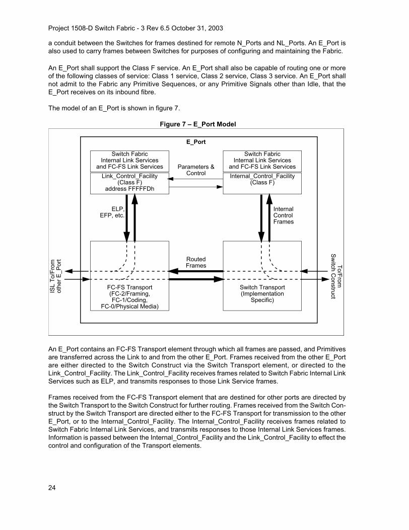
Project 1508-D Switch Fabric - 3 Rev 6.5 October 31, 2003
a conduit between the Switches for frames destined for remote N_Ports and NL_Ports. An E_Port isalso used to carry frames between Switches for purposes of configuring and maintaining the Fabric.
An E_Port shall support the Class F service. An E_Port shall also be capable of routing one or moreof the following classes of service: Class 1 service, Class 2 service, Class 3 service. An E_Port shallnot admit to the Fabric any Primitive Sequences, or any Primitive Signals other than Idle, that theE_Port receives on its inbound fibre.
The model of an E_Port is shown in figure 7.
Figure 7 – E_Port Model
An E_Port contains an FC-FS Transport element through which all frames are passed, and Primitivesare transferred across the Link to and from the other E_Port. Frames received from the other E_Portare either directed to the Switch Construct via the Switch Transport element, or directed to theLink_Control_Facility. The Link_Control_Facility receives frames related to Switch Fabric Internal LinkServices such as ELP, and transmits responses to those Link Service frames.
Frames received from the FC-FS Transport element that are destined for other ports are directed bythe Switch Transport to the Switch Construct for further routing. Frames received from the Switch Con-struct by the Switch Transport are directed either to the FC-FS Transport for transmission to the otherE_Port, or to the Internal_Control_Facility. The Internal_Control_Facility receives frames related toSwitch Fabric Internal Link Services, and transmits responses to those Internal Link Services frames.Information is passed between the Internal_Control_Facility and the Link_Control_Facility to effect thecontrol and configuration of the Transport elements.
E_Port
FC-FS Transport(FC-2/Framing,FC-1/Coding,
FC-0/Physical Media)
Switch Transport(Implementation
Specific)
Link_Control_Facility(Class F)
address FFFFFDh
Switch FabricInternal Link Services
and FC-FS Link ServicesInternal_Control_Facility
(Class F)
Switch FabricInternal Link Services
and FC-FS Link Services
RoutedFrames
ELP,EFP, etc.
InternalControlFrames
Parameters &Control
ISL
To/F
rom
othe
r E_P
ort To/From
Switch C
onstruct
24

Project 1508-D Switch Fabric - 3 Rev 6.5 October 31, 2003
5.6 B_Port Operation
A Bridge Port (B_Port) is a port that is used to connect a Switch to Bridge device. It normally functionsas a conduit between the Switch and the Bridge for frames destined for or through a Bridge device. AB_Port is also used to carry frames between a Switch and the Bridge device for purposes of configur-ing the Bridge device.
A B_Port shall support Class F service. A B_Port shall also be capable of forwarding one or more ofthe following classes of service: Class 1 service, Class 2 service, Class 3 service. A B_Port shall notadmit to the Fabric any Primitive Sequences, or any Primitive Signals other than Idle, that the B_Portreceives on its inbound fibre.
The model of a B_Port is shown in figure 8.
Figure 8 – B_Port Model
A B_Port contains an FC-FS Transport element through which pass all frames and Primitives trans-ferred across the Link to and from the E_Port. Frames received from the attached E_Port are eitherdirected to the Bridge Construct via the Bridge Transport element, or directed to theLink_Control_Facility. The Link_Control_Facility receives frames related to Bridge Fabric Internal LinkServices such as ELP, and transmits responses to those Link Service frames.
Frames received from the FC-FS Transport element that are destined for other ports are directed bythe Bridge Transport to the Bridge Construct for further forwarding. Frames received from the BridgeConstruct by the Bridge Transport are directed either to the FC-FS Transport for transmission to theother E_Port, or to the Internal_Control_Facility. The Internal_Control_Facility receives frames relatedto Bridge Fabric Internal Link Services, and transmits responses to those Internal Link Servicesframes. Information is passed between the Internal_Control_Facility and the Link_Control_Facility toeffect the control and configuration of the Transport elements.
Internal Control Facility(Class F)
BridgeInternal Link Services
and FC-FS Link Services
Link control Facility(Class F)
Address FFFFFDh
FC-FS Transport(FC-2/Framing,FC-1/Coding,
FC-0/Physical Media)’
Bridge Transport(Implementation Specific)
BridgeInternal Link Services
and FC-FS Link Services
ELP,etc.
BridgedFrames
InternalControlFrames
B_Port
To/F
rom
E_po
rt
To/FromBridge C
onstruct
25

Project 1508-D Switch Fabric - 3 Rev 6.5 October 31, 2003
The Bridge Port utilizes Class F service as a connectionless service exchanging frames betweenE_ports and B_Ports. The definition of Class F function and Class F rules apply to both E_ports andB_Ports as defined in clause 5.8.
5.7 Inter-Switch Link Behavior
Inter-Switch Links (ISLs) are used by Switches to transmit and receive frames with other Switches orBridge devices. An ISL always connects exactly one E_Port on a Switch to exactly one E_Port on an-other Switch or exactly one B_Port on a Bridge device.
An ISL follows the FC-0, FC-1, and FC-2 protocols defined for point-to-point Links as defined in FC-FS, with the exception that Class F frames are allowed to transit the Link. R_RDY shall be used forthe management of buffer-to-buffer flow control of Class F frames on the ISL prior to the completionof the exchange of Link parameters (see 6.1.4 and 7.2); an alternate method of buffer-to-buffer flowcontrol may be defined in that process.
For purposes of defining and maintaining the Fabric Configuration, an ISL may be designated as aPrincipal ISL. The Principal ISL is a path that is used during configuration and address assignment toroute Class F configuration frames, and is therefore a known path between two Switches. If a PrincipalISL is lost, there may be no other available paths between the two affected Switches, so as a resultthe Fabric Configuration is possibly broken and shall be rebuilt (by issuing the BF SW_ILS,see 6.1.11). If a non-Principal ISL is lost, at least one other path is known to be available between theSwitches (i.e., the Principal ISL), therefore the lost ISL may be resolved via a routing change.
A Switch discovers the Principal ISL(s) during the process of Principal Switch Selection (see 7.3) andAddress Distribution (see 7.4). During this process, the Switch identifies two kinds of Principal ISLs.The Principal ISL that leads towards the Principal Switch is called the upstream Principal ISL. Allframes from the Switch to the Principal Switch are sent via the upstream Principal ISL. The PrincipalSwitch has no upstream Principal ISL; all other Switches have exactly one upstream Principal ISL.
A Principal ISL that leads away from the Principal Switch is called the downstream Principal ISL. Anyframe sent by the Switch to another Switch as a result of a frame received on the upstream PrincipalISL is sent via the downstream Principal ISL that leads towards that Switch. The Principal Switch mayhave one or more downstream Principal ISLs; all other Switches may have zero or more downstreamPrincipal ISLs.
Principal ISLs are further illustrated in figure 9.
26

Project 1508-D Switch Fabric - 3 Rev 6.5 October 31, 2003
Figure 9 – Principal Inter-Switch Links
5.8 Class F Service
5.8.1 Class F Function
Class F Service is a connectionless service with notification of non-delivery betweenInterconnect_Ports. Class F service is used for control, coordination, and configuration of the Fabric.Class F Service is defined by this Standard for use by Switches communicating across Inter-SwitchLinks.
A Class F Service is requested by an Interconnect_Port on a frame by frame basis. The Fabric routesthe frame to the destination Interconnect_Port. If an Interconnect_Port transmits consecutive framesto multiple destinations, the Fabric demultiplexes them to the requested destinations. Class F delimit-ers are used to indicate the requested service and to initiate and terminate one or more Sequencesas described in FC-FS.
5.8.2 Class F Rules
To provide Class F Service, the transmitting and receiving Interconnect_Ports and the Fabric shallobey the following rules:
a) Except for some Switch Fabric Internal Link Service protocols, an Interconnect_Port is requiredto have exchanged Link parameters (see 6.1.4 and 7.2) with the associated destination withwhich it intends to communicate (Login).
SwitchA
SwitchD
SwitchF
SwitchC
SwitchE
SwitchB
Principal ISLISL
Upstream: noneDownstream: AB, AC
Upstream: CADownstream: none
Upstream: BADownstream: BD, BE
Upstream: EBDownstream: EF
Upstream: DBDownstream: none
Upstream: FEDownstream: none
Switch A is thePrincipal Switch
27

Project 1508-D Switch Fabric - 3 Rev 6.5 October 31, 2003
b) The Fabric routes the frames without establishing a Dedicated Connection between communi-cating Interconnect_Ports. To obtain Class F service, the Interconnect_Port shall use Class Fdelimiters as defined in 5.8.3. (Connectionless service)
c) An Interconnect_Port is allowed to send consecutive frames to one or more destinations. Thisenables an Interconnect_Port to demultiplex multiple Sequences to a single or multiple destina-tions concurrently (Demultiplexing).
d) A given Interconnect_Port may receive consecutive frames from different sources. Eachsource is allowed to send consecutive frames for one or more Sequences. (multiplexing)
e) An Interconnect_Port addressed by a Class F frame shall provide an acknowledgment to thesource for each valid Data frame received. The destination Interconnect_Port shall use ACK_1for the acknowledgment. If a Switch is unable to deliver the ACK_1 frame, the Switch shall re-turn an F_BSY or F_RJT. (Acknowledgment)
f) The Sequence Initiator shall increment the SEQ_CNT field of each successive frame transmit-ted within a Sequence. However, the Switches may not guarantee delivery to the destination inthe same order of transmission. (Non-sequential delivery)
g) Since the SOFf delimiter does not indicate whether a frame is the first frame of a Sequence, thestarting SEQ_CNT of every Sequence shall be zero. (Sequence reassembly)
h) An Interconnect_Port may originate multiple Exchanges and initiate multiple Sequences withone or more Interconnect_Ports. The Interconnect_Port originating an Exchange shall assignan X_ID unique to the Originator called OX_ ID and the Responder of the Exchange shall as-sign an X_ID unique to the responder called RX_ID. The value of OX_ ID or RX_ID is unique toa given Interconnect_Port. The Sequence Initiator shall assign a SEQ_ID, for each Sequence itinitiates, that is unique to the Sequence Initiator and the respective Sequence Recipient pairwhile the Sequence is Open. (Concurrent Exchanges and Sequences)
i) Each Interconnect_Port exercises buffer-to-buffer flow control with the Interconnect_Port towhich it is directly attached. End-to-end flow control is performed by communicatingInterconnect_Ports. ACK_1 frames are used to perform end-to-end flow control and R_RDY isused for buffer-to-buffer flow control. However, some other agreed upon methods outside thescope of this standard may be used for buffer-to-buffer flow control. (Dual flow control)
j) If a Switch is unable to deliver the frame to the destination Interconnect_Port, then the sourceis notified of each frame not delivered by an F_BSY or F_RJT frame with corresponding D_ ID,S_ID, OX_ID, RX_ID, SEQ_ID, and SEQ_CNT from the Switch. The source is also notified ofvalid frames busied or rejected by the destination Interconnect_Port by P_BSY or P_RJT.(Non-delivery)
k) A busy or reject may be issued by an intermediate Interconnect_Port or the destinationInterconnect_Port with a valid reason code. (Busy/reject)
l) If a Class F Data frame is busied, the sender shall retransmit the busied frame up to the abilityof the sender to retry, including zero. (Retransmit)
m) The Credit established during the ELP protocol by interchanging Link Parameters shall be hon-ored. Class F may share Credit with other classes of service. (Credit)
28

Project 1508-D Switch Fabric - 3 Rev 6.5 October 31, 2003
n) Effective transfer rate between any given Interconnect_Port pair is dependent upon the numberof Interconnect_Ports a given Interconnect_Port is multiplexing and demultiplexing. (Band-width)
o) Frames within a Sequence are tracked on a Sequence_Qualifier and SEQ_CNT basis. (Track-ing)
p) An Interconnect_Port shall be able to recognize SOF delimiters for Class N service, whether ornot all classes of service are supported by the Port. (Invalid Class)
q) An Interconnect_Port addressed by a Vendor Specific Class F frame, shall send an LS_RJT ifit does not understand the frame. A Vendor Specific Class F frame is indicated by an R_CTLfield value of F0h. (Vendor specific)
r) An Interconnect_Port shall support insertion of Class F frames onto an established Class 1Dedicated Connection. However, this insertion shall not cause loss of any Class 1 frames. ASwitch may abort (EOFa) or discard an Intermixed Class 2 or Class 3 frame in progress if itstransmission of a Class F frame interferes. A Switch shall not abort an Inserted Class F frame.(Class F intermix)
s) An Interconnect_Port shall use R_RDY and FC-FS buffer-to-buffer flow control with theInterconnect_Port to which it is directly attached, until after the exchange of Link parameters(see 6.1.4 and 7.2). The BB_Credit prior to the exchange of Link parameters shall be 1. An In-terconnnect Port may agree to use an alternate buffer-to-buffer credit model for Class F follow-ing the successful exchange of Link parameters. (Alternate credit models)
t) A Class F frame shall be forwarded to its destination without checking by an intermediate enti-ty. A Class F frame not destined for the receiving E_Port (or E_Port's domain) shall always beforwarded regardless of whether or not the receiving E_Port recognizes the frame. (Frame for-warding)
5.8.3 Class F Frame Format
Class F frames shall use the Frame_Header defined in FC-FS. The Class F frame format is shown infigure 10. The Start_of_Frame Fabric (SOFf) delimiter shall precede the frame content of all Class Fframes. The Data Field size of all Class F frames shall be less than or equal to 256 bytes prior to thesuccessful completion of Exchange Link Parameters (see 6.1.4; Exchange Link Parameters establish-es the maximum receive frame size for Class F frames). All Class F frames shall include the CRC de-fined in FC-FS. The End_of_Frame Normal (EOFn) delimiter shall immediately follow the CRC of allnormally completed Class F Data frames and all normally completed Class F Link_Control frames ex-cept the last frame of a Sequence. The End_of_Frame Terminate (EOFt) delimiter shall immediatelyfollow the CRC of all Class F Link_Control frames that indicate the last frame of a normally terminatedSequence. A Class F frame is preceded and followed by Primitive Signals as defined in FC-FS.
An Interconnect_Port or Switch may invalidate or discard without notification any incorrectly formedClass F frame, or any Class F frame with a code violation or CRC error.
29

Project 1508-D Switch Fabric - 3 Rev 6.5 October 31, 2003
Figure 10 – Class F Frame Format
5.8.4 Class F Flow Control
Class F service uses both buffer-to-buffer and end-to-end flow controls. R_RDY is used for buffer-to-buffer flow control. R_RDY is transmitted by the Interconnect_Port at one end of the ISL, to theInterconnect_Port at the other end of the ISL, to indicate that a buffer is available for further frame re-ception by the first Interconnect_Port. This process operates in both directions on the ISL.
After the successful exchange of Link Parameters, an alternate method of buffer-to-buffer flow controlmay be established on an ISL (see 7.2). This alternate method of buffer-to-buffer flow control remainsin effect until a Link Offline or Link Failure occurs, or a new set of Link Parameters is successfully ex-changed between the Interconnect_Ports.
ACK_1 frames are used to perform end-to-end flow control. ACK_1 frames shall be formatted as de-scribed in 5.8.3. The ACK_0 Link Control frame shall not be used for Class F service.
Frame Content
Fill WordsEOFn orEOFtSOFf Frame Header Data Field
(4 bytes)
Fill Words
(24 bytes) (0 to 2112 bytes) (4 bytes)
CRC
(4 bytes)
Class F Frame
30

Project 1508-D Switch Fabric - 3 Rev 6.5 October 31, 2003
6 Internal Link Services
6.1 Switch Fabric Internal Link Services (SW_ILS)
6.1.1 SW_ILS Overview
This subclause describes Link Services that operate internal to the Fabric between Switches. In thecase of Exchange Link Parameters (ELP), Link Services also operate internal to the Fabric betweenSwitches and Bridge devices. All SW_ILS frames shall be transmitted using the FT_1 frame format viathe Class F service. The following defines the header fields of all SW_ILS frames:
R_CTL: This field shall be set to 02h for all request frames, and to 03h for all reply frames.
CS_CTL: This field shall be set to 00h.
D_ID and S_ID: Set as indicated for the specific SW_ILS.
TYPE: This field shall be set to 22h, indicating Fibre Channel Fabric Switch Services.
All other fields shall be set as appropriate according to the rules defined in FC-FS. The first word inthe payload specifies the Command Code. The Command Codes are summarized in table 3.
Table 3 – SW_ILS Command Codes (Part 1 of 2)Encoded Value
(hex) Description Abbr.
01 00 00 00 Switch Fabric Internal Link Service Reject SW_RJT
02 xx xx xx Switch Fabric Internal Link Service Accept SW_ACC
10 00 00 00 Exchange Link Parameters ELP
11 xx xx xx Exchange Fabric Parameters EFP
12 00 00 00 Domain Identifier Assigned DIA
13 00 xx xx Request Domain_ID RDI
14 00 00 00 Hello HLO
15 00 00 00 Link State Update LSU
16 00 00 00 Link State Acknowledgement LSA
17 00 00 00 Build Fabric BF
18 00 00 00 Reconfigure Fabric RCF
1B 00 00 00 Inter-Switch Registered State Change Notification SW_RSCN
1E 00 00 00 Distribute Registered Link Incident Records DRLIR
20 00 00 00 Disconnect Class 1 Connection DSCN
31

Project 1508-D Switch Fabric - 3 Rev 6.5 October 31, 2003
Unless otherwise specified, the rules regarding the following aspects of Switch Fabric Internal LinkServices are as defined for the Extended Link Services in FC-FS (e.g., Sequence and Exchange Man-agement, error detection and recovery). Time-out values for specific SW_ILS’s and the actions follow-ing a time-out expiration are specified in 12.2.
6.1.2 Switch Fabric Internal Link Service Accept (SW_ACC)
The Switch Fabric Internal Link Service Accept reply Sequence shall notify the transmitter of anSW_ILS request that the SW_ILS request Sequence has been completed. The first word of the Pay-load shall contain 02 xx xx xxh. The remainder of the Payload is unique to the specific SW_ILS re-quest.
21 00 00 00 Obsoleted in FC-SW-3 LOOPD
22 00 xx xx Merge Request MR
23 00 xx xx Acquire Change Authorization ACA
24 00 00 00 Release Change Authorization RCA
25 xx xx xx Stage Fabric Configuration SFC
26 00 00 00 Update Fabric Configuration UFC
28 xx xx xx Reserved for FC-BB-2 Use (See reference [10])
30 00 xx xx Exchange Switch Capabilities ESC
31 00 00 00 Exchange Switch Support ESS
32 00 00 00 Reserved for FC-SP Use (See reference [13])
33 00 00 00 Reserved for FC-SP Use (See reference [13])
34 00 00 00 Merge Request Resource Allocation MRRA
40 xx xx xx Reserved for FC-SP Use (See reference [13])
41 xx xx xx Reserved for FC-SP Use (See reference [13])
70 00 00 00to
7F FF FF FFVendor Specific
90 00 00 00to
9F FF FF FFVendor Specific
others Reserved
Table 3 – SW_ILS Command Codes (Part 2 of 2)Encoded Value
(hex) Description Abbr.
32

Project 1508-D Switch Fabric - 3 Rev 6.5 October 31, 2003
Protocol: SW_ACC may be sent as a reply Sequence to an SW_ILS request. An SW_ACC shall notbe sent for HLO, LSU, and LSA Request Sequences.
Format: FT–1
Addressing: The S_ID field shall be set to the value of the D_ID field in the SW_ILS request. TheD_ID field shall be set to the value of the S_ID field in the SW_ILS request.
Payload: The Payload content following the first word is defined within individual SW_ILS requests.
6.1.3 Switch Fabric Internal Link Service Reject (SW_RJT)
The Switch Fabric Internal Link Service Reject shall notify the transmitter of an SW_ILS request thatthe SW_ILS request Sequence has been rejected. A four-byte reason code shall be contained in theData_Field. SW_RJT may be transmitted for a variety of conditions that may be unique to a specificSW_ILS request.
Protocol: SW_RJT may be sent as a reply Sequence to an SW_ILS request. An SW_RJT shall notbe sent for HLO, LSU, and LSA Request Sequences.
Format: FT–1
Addressing: The S_ID field shall be set to the value of the D_ID field in the SW_ILS request. TheD_ID field shall be set to the value of the S_ID field in the SW_ILS request.
Payload: The format of the SW_RJT reply Payload is shown in table 4.
Table 4 – SW_RJT Payload
ItemSize
Bytes
01 00 00 00h 4
Reserved 1
Reason Code 1
Reason Code Explanation 1
Vendor Specific 1
33

Project 1508-D Switch Fabric - 3 Rev 6.5 October 31, 2003
Reason Code: The Reason Codes are summarized in table 5.
Invalid SW_ILS command code: The Command Code is not recognized by the recipient.
Invalid revision level: The recipient does not support the specified revision level.
Logical error: The request identified by the Command Code and the Payload content is invalid or log-ically inconsistent for the conditions present.
Invalid payload size: The size of the Payload is inconsistent with the Command Code and/or anyLength fields in the Payload.
Logical busy: The recipient is busy and is unable to process the request at this time.
Protocol error: An error has been detected that violates the protocol.
Unable to perform command request: The recipient is unable to perform the request.
Command not supported: The command code is not supported by the recipient.
Invalid Attachment: The recipient is in the Invalid Attachment state.
Vendor Specific Error: The Vendor Specific field indicates the error condition.
Table 5 – SW_RJT Reason CodesEncoded Value
(hex) Description
01 Invalid SW_ILS command code
02 Invalid revision level
03 Logical error
04 Invalid payload size
05 Logical busy
07 Protocol error
09 Unable to perform command request
0B Command not supported
0C Invalid Attachment
FF Vendor Specific error
others Reserved
34

Project 1508-D Switch Fabric - 3 Rev 6.5 October 31, 2003
Reason Code Explanation: The Reason Code Explanation is summarized in table 6.
Table 6 – SW_RJT Reason Code Explanation (Part 1 of 2)Encoded Value
(hex) Description
00 No additional explanation
01 Class F Service Parameter error
03 Class N Service Parameter error
04 Unknown Flow Control code
05 Invalid Flow Control Parameters
0D Invalid Port_Name
0E Invalid Switch_Name
0F R_A_TOV or E_D_TOV mismatch
10 Invalid Domain_ID_List
19 Command already in progress
29 Insufficient resources available
2A Domain_ID not available
2B Invalid Domain_ID
2C Request not supported
2D Link Parameters not yet established
2E Requested Domain_IDs not available
2F E_Port is Isolated
31 Authorization Faileda
32 Authentication Failed
33 Incompatible Security Attribute
34 Checks in Progress
41 Invalid Data Lengthb
a The range of values 30h-3Fh are used to indicate Security reason code explanations.
b The range of values 40h-4Fh are used to indicate Zoning reason code explanations.
35

Project 1508-D Switch Fabric - 3 Rev 6.5 October 31, 2003
Vendor Specific: This field is valid when the Reason Code indicates a Vendor Specific error.
6.1.4 Exchange Link Parameters (ELP)
The Exchange Link Parameters Switch Fabric Internal Link Service requests the exchange of Link Pa-rameters between two Interconnect_Ports connected via an ISL. The exchange of Link Parametersestablishes the operating environment between the two Interconnect_Ports, and the capabilities of theSwitches or Bridge devices that are connected by the Interconnect_Ports. When an ELP is receivedby an Interconnect_Port, any Active or Open Class F Sequences between the two Interconnect_Ports,and any Dedicated Connections, shall be abnormally terminated (prior to transmission of the SW_ACCreply Sequence.
Use of the ELP SW_ILS for Switch Port initialization is described in 7.2.
Protocol:
Exchange Link Parameters (ELP) Request SequenceAccept (SW_ACC) Reply Sequence
Format: FT–1
Error Detection and Recovery: The Time-out value for ELP shall be E_D_TOV.
42 Unsupported Command
44 Not Authorized
45 Invalid Request
46 Fabric Changing
47 Update Not Staged
48 Invalid Zone Set Format
49 Invalid Data
4A Unable to Merge
4B Zone Set Size Not Supported
others Reserved
Table 6 – SW_RJT Reason Code Explanation (Part 2 of 2)Encoded Value
(hex) Description
a The range of values 30h-3Fh are used to indicate Security reason code explanations.
b The range of values 40h-4Fh are used to indicate Zoning reason code explanations.
36

Project 1508-D Switch Fabric - 3 Rev 6.5 October 31, 2003
Addressing: For use in Switch Port initialization, the S_ID field shall be set to FFFFFDh, indicatingthe Fabric Controller of the originating Switch; the D_ID field shall be set to FFFFFDh, indicating theFabric Controller of the destination Switch.
Payload: The format of the ELP request Payload is shown in table 7.
Revision: This field denotes the revision of the protocol. This revision has the value of 3.
Flags: This field contains flag bits that provide additional information about the ELP. The followingflag bit is defined.
Bit 15, the Bridge Port bit, shall indicate whether the sending port is a B_Port. If bit 15 iszero, the sending port is an E_Port and not a B_Port. If bit 15 is one, the sending port is aB_port.
Bits 14-0 shall be reserved.
Table 7 – ELP Request Payload
ItemSize
Bytes
10000000h 4
Revision 1
Flags 2
BB_SC_N 1
R_A_TOV 4
E_D_TOV 4
Requester Interconnect_Port_Name 8
Requester Switch_Name 8
Class F Service Parameters 16
Class 1 Interconnect_Port Parameters 4
Class 2 Interconnect_Port Parameters 4
Class 3 Interconnect_Port Parameters 4
Reserved 20
ISL Flow Control Mode 2
Flow Control Parameter Length (N) 2
Flow Control Parameters N
37
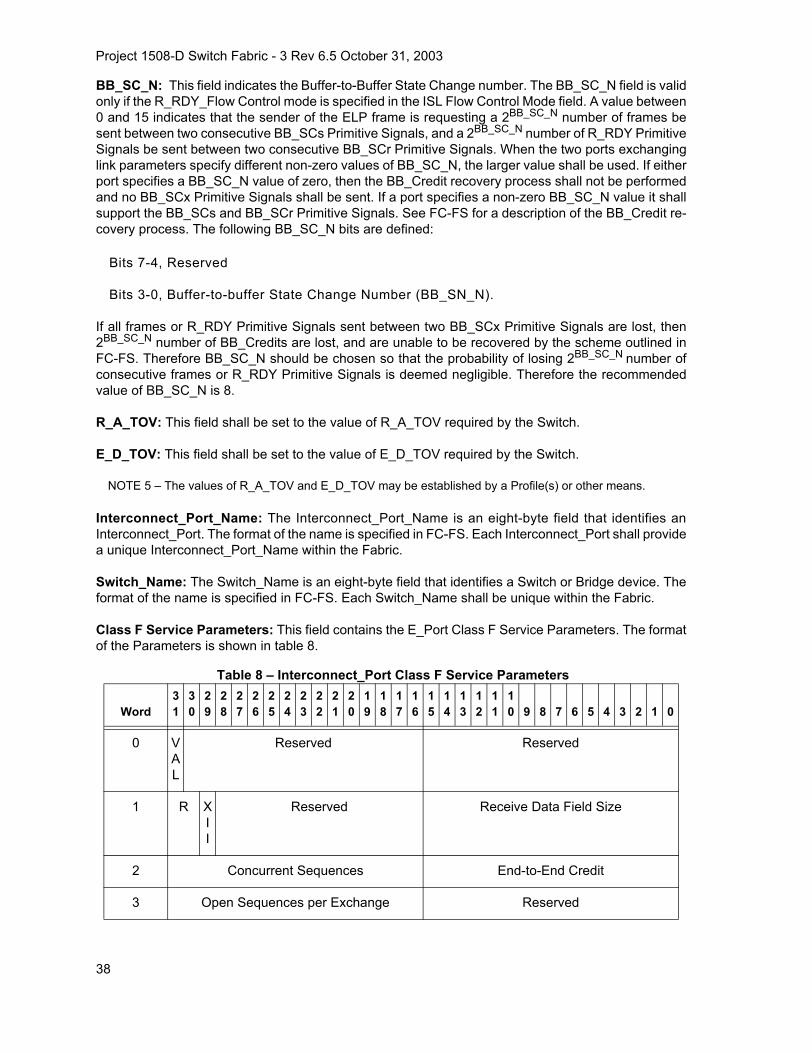
Project 1508-D Switch Fabric - 3 Rev 6.5 October 31, 2003
BB_SC_N: This field indicates the Buffer-to-Buffer State Change number. The BB_SC_N field is validonly if the R_RDY_Flow Control mode is specified in the ISL Flow Control Mode field. A value between0 and 15 indicates that the sender of the ELP frame is requesting a 2BB_SC_N number of frames besent between two consecutive BB_SCs Primitive Signals, and a 2BB_SC_N number of R_RDY PrimitiveSignals be sent between two consecutive BB_SCr Primitive Signals. When the two ports exchanginglink parameters specify different non-zero values of BB_SC_N, the larger value shall be used. If eitherport specifies a BB_SC_N value of zero, then the BB_Credit recovery process shall not be performedand no BB_SCx Primitive Signals shall be sent. If a port specifies a non-zero BB_SC_N value it shallsupport the BB_SCs and BB_SCr Primitive Signals. See FC-FS for a description of the BB_Credit re-covery process. The following BB_SC_N bits are defined:
Bits 7-4, Reserved
Bits 3-0, Buffer-to-buffer State Change Number (BB_SN_N).
If all frames or R_RDY Primitive Signals sent between two BB_SCx Primitive Signals are lost, then2BB_SC_N number of BB_Credits are lost, and are unable to be recovered by the scheme outlined inFC-FS. Therefore BB_SC_N should be chosen so that the probability of losing 2BB_SC_N number ofconsecutive frames or R_RDY Primitive Signals is deemed negligible. Therefore the recommendedvalue of BB_SC_N is 8.
R_A_TOV: This field shall be set to the value of R_A_TOV required by the Switch.
E_D_TOV: This field shall be set to the value of E_D_TOV required by the Switch.
NOTE 5 – The values of R_A_TOV and E_D_TOV may be established by a Profile(s) or other means.
Interconnect_Port_Name: The Interconnect_Port_Name is an eight-byte field that identifies anInterconnect_Port. The format of the name is specified in FC-FS. Each Interconnect_Port shall providea unique Interconnect_Port_Name within the Fabric.
Switch_Name: The Switch_Name is an eight-byte field that identifies a Switch or Bridge device. Theformat of the name is specified in FC-FS. Each Switch_Name shall be unique within the Fabric.
Class F Service Parameters: This field contains the E_Port Class F Service Parameters. The formatof the Parameters is shown in table 8.
Table 8 – Interconnect_Port Class F Service Parameters
Word31
30
29
28
27
26
25
24
23
22
21
20
19
18
17
16
15
14
13
12
11
10 9 8 7 6 5 4 3 2 1 0
0 VAL
Reserved Reserved
1 R XII
Reserved Receive Data Field Size
2 Concurrent Sequences End-to-End Credit
3 Open Sequences per Exchange Reserved
38

Project 1508-D Switch Fabric - 3 Rev 6.5 October 31, 2003
The Class F Service Parameters are defined as follows:
a) VAL (Class Valid): This bit shall be set to one.
b) XII (X_ID Interlock): This bit when one indicates that the Interconnect_Port supplying this pa-rameter requires that an interlock be used during X_ID assignment in Class F. In X_ID assign-ment, the Sequence Initiator shall set the Recipient X_ID value to FFFFh in the first Data frameof a Sequence, and the Recipient shall supply its X_ID in the ACK frame corresponding to thefirst Data frame of a Sequence. The Sequence Initiator shall not transmit additional frames untilthe corresponding ACK is received. Following reception of the ACK, the Sequence Initiatorcontinues transmission of the Sequence using both assigned X_ID values.
c) Receive Data Field Size: This field shall specify the largest Data Field size in bytes for an FT_1frame that may be received by the Interconnect_Port supplying the Parameters as a SequenceRecipient for a Class F frame. Values less than 256 or greater than 2112 are invalid. Valuesshall be a multiple of four bytes.
d) Concurrent Sequences: This field shall specify the number of Sequence Status Blocks provid-ed by the Interconnect_Port supplying the Parameters for tracking the progress of a Sequenceas a Sequence Recipient. The maximum number of Concurrent Sequences that may be speci-fied is 255. A value of zero in this field is reserved. In Class F, the value of SEQ_ID shall rangefrom 0 to 255, independent of the value in this field. An Interconnect_Port is allowed to respondwith P_BSY to a frame initiating a new Sequence if Interconnect_Port resources are not avail-able.
e) End-to-End Credit: End-to-end credit is the maximum number of Class F Data frames that maybe transmitted by an Interconnect_Port without receipt of accompanying ACK orLink_Response frames. The minimum value of end-to-end credit is one. The end-to-end creditfield specified is associated with the number of buffers available for holding the Data_Field of aClass F frame and processing the contents of that Data_Field by the Interconnect_Port supply-ing the Parameters. Bit 15 of this field shall be set to zero. A value of zero for this field is re-served.
f) Open Sequences per Exchange: The value of the Open Sequences per Exchange shall specifythe maximum number of Sequences that may be Open at one time at the Recipient between apair of Interconnect_Ports for one Exchange. This value plus two shall specify the number of in-stances of Sequence Status that shall be maintained by the Recipient for a single Exchange inthe Exchange Status Block. This value is used for Exchange and Sequence tracking. The valuein this field limits the link facility resources required for error detection and recovery.
Interconnect_Port Parameters indicate that the Interconnect_Port is capable of transporting the indi-cated Class of Service, and the conditions under which it may transport the Class. One word of theELP Payload is allocated for each Class.
39

Project 1508-D Switch Fabric - 3 Rev 6.5 October 31, 2003
Class 1 Interconnect_Port Parameters: This field contains the Class 1 Interconnect_Port Parame-ters. The format of the Parameters is shown in table 9.
The Class 1 Interconnect_Port Parameters are defined as follows:
a) VAL (Class Valid): This bit is set to one if the Interconnect_Port supports Class 1. If this bit iszero, all other Class 1 Interconnect_Port Parameters shall be invalid.
b) IMX (Intermix): This bit is set to one if the Interconnect_Port may perform Intermix as defined inFC-FS. Intermix shall be functional only if both Interconnect_Ports indicate support for this fea-ture.
c) XPS (Transparent Mode Stacked Connect Request): This bit is set to one if theInterconnect_Port may perform Transparent Mode Stacked Connect Requests as defined inFC-FS. Transparent Mode Stacked Connect Requests shall be functional only if bothInterconnect_Ports indicate support for this feature. A Switch shall not indicate support for bothXPS and LKS.
d) LKS (Lock-down Mode Stacked Connect Request): This bit is set to one if theInterconnect_Port may perform Lock-down Mode Stacked Connect Requests as defined in FC-FS. Lock-down Mode Stacked Connect Requests shall be functional only if bothInterconnect_Ports indicate support for this feature. A Switch shall not indicate support for bothXPS and LKS.
e) Receive Data Field Size: This field shall specify the largest Data Field size in bytes for an FT_1frame that may be received by the Interconnect_Port supplying the Parameters for a Class 1frame. Values less than 256 or greater than 2112 are invalid. Values shall be a multiple of fourbytes.
Class 2 Interconnect_Port Parameters: This field contains the Class 2 Interconnect_Port Parame-ters. The format of the Parameters is shown in table 10.
The Class 2 Interconnect_Port Parameters are defined as follows:
a) VAL (Class Valid): This bit shall be set to one if the Interconnect_Port supports Class 2. If thisbit is zero, all other Class 2 Interconnect_Port Parameters shall be invalid.
Table 9 – Class 1 Interconnect_Port Parameters
Word31
30
29
28
27
26
25
24
23
22
21
20
19
18
17
16
15
14
13
12
11
10 9 8 7 6 5 4 3 2 1 0
0 VAL
IMX
XPS
LKS
Reserved Receive Data Field Size
Table 10 – Class 2 Interconnect_Port Parameters
Word31
30
29
28
27
26
25
24
23
22
21
20
19
18
17
16
15
14
13
12
11
10 9 8 7 6 5 4 3 2 1 0
0 VAL
R R R SEQ
Reserved Receive Data Field Size
40

Project 1508-D Switch Fabric - 3 Rev 6.5 October 31, 2003
b) SEQ (Sequential Delivery): If this bit is set to one by an Interconnect_Port, it is indicating thatthe Switch is able to guarantee sequential delivery (as defined in FC-FS) of Class 2 frames.Sequential Delivery shall be functional only if both Interconnect_Ports indicate support for thisfeature.
c) Receive Data Field Size: This field shall specify the largest Data Field size in bytes for an FT_1frame that may be received by the Interconnect_Port supplying the Parameters for a Class 2frame. Values less than 256 or greater than 2112 are invalid. Values shall be a multiple of fourbytes.
Class 3 Interconnect_Port Parameters: This field contains the Class 3 Interconnect_Port Parame-ters. The format of the Parameters is shown in table 11.
The Class 3 Interconnect_Port Parameters are defined as follows:
a) VAL (Class Valid): This bit shall be set to one if the Interconnect_Port supports Class 3. If thisbit is zero, all other Class 3 Interconnect_Port Parameters shall be invalid.
b) SEQ (Sequential Delivery): If this bit is set to one by an Interconnect_Port, it is indicating thatthe Switch is able to guarantee sequential delivery (as defined in FC-FS) of Class 3 frames.Sequential Delivery shall be functional only if both Interconnect_Ports indicate support for thisfeature.
c) Receive Data Field Size: This field shall specify the largest Data Field size in bytes for an FT_1frame that may be received by the Interconnect_Port supplying the Parameters for a Class 3frame. Values less than 256 or greater than 2112 are invalid. Values shall be a multiple of fourbytes.
ISL Flow Control Mode: This field contains a code that specifies the Flow Control method supportedby the Interconnect_Port. Table 12 shows the allowed values for this field.
Flow Control Parameter Length: This field specifies the length in bytes of the Flow Control Param-eters that follow. Values shall be a multiple of four. A value of zero indicates no parameters follow.
Table 11 – Class 3 Interconnect_Port Parameters
Word31
30
29
28
27
26
25
24
23
22
21
20
19
18
17
16
15
14
13
12
11
10 9 8 7 6 5 4 3 2 1 0
0 VAL
R R R SEQ
Reserved Receive Data Field Size
Table 12 – ISL Flow Control Mode Values
Value (hex) Usage
0001 Vendor Specific
0002 R_RDY Flow Control
0003 - 1FFF Vendor Specific
Other Values Reserved
41

Project 1508-D Switch Fabric - 3 Rev 6.5 October 31, 2003
Flow Control Parameters: These parameters contain information used to configure Flow Control forthe ISL. Flow control parameters are specific to a given flow control mode.
R_RDY Flow Control: A value of 0002h in the ISL Flow Control Mode field indicates that R_RDY FlowControl (as defined in FC-FS) shall be used. When R_RDY Flow Control mode is used, the Flow Con-trol Parameter Length field shall be set to 20h and the Flow Control Parameters field shall contain thefields as shown in table 13. Values other than 0002h for ISL Flow Control Mode are not required tofollow the Flow Control Parameter Field format shown in table 13.
Buffer-to-buffer Credit: The BB_Credit field specified shall be associated with the number of buffersavailable for holding Class 1 connect-request, Class 2, Class 3 or Class F frames received from theInterconnect_Port. The Buffer-to-buffer Credit shall be a single value that represents the total buffer-to-buffer Credit available for Class 1 SOFC1 frames, all Class 2 frames, and all Class 3 frames. Thebuffer-to-buffer credit value may also be applied to class F frames.
Compatibility Parameters: This field contains associated compatibility parameters to assist in assur-ing backward compatibility with existing implementations.
NOTE 6 – Recommended Compatibility Parameter values are described in FC-MI (reference [8]).
Reply Switch Fabric Internal Link Service Sequence:
Service Reject (SW_RJT)Signifies the rejection of the ELP request
Accept (SW_ACC)Signifies acceptance of the ELP request.
– Accept Payload
Table 13 – Flow Control Parameters
Item SizeBB_Credit 4
Compatibility Parameters
16
42

Project 1508-D Switch Fabric - 3 Rev 6.5 October 31, 2003
Payload: The format of the ELP Accept Payload is shown in table 14.
The fields in table 14 are the same as defined in table 7.
6.1.5 Exchange Fabric Parameters (EFP)
The Exchange Fabric Parameters Switch Fabric Internal Link Service requests the exchange of FabricParameters between two E_Ports connected via an ISL. The exchange of Fabric Parameters is usedto establish the address allocation within the Fabric. When an E_Port receives EFP from anotherE_Port, all Active or Open Class F Sequences and Dedicated Connections shall be unaffected.
Use of the EFP SW_ILS for Fabric Configuration is described in 7.3 and 7.4.
Protocol:
Exchange Fabric Parameters (EFP) request SequenceAccept (SW_ACC) Reply Sequence
Table 14 – ELP Accept Payload
ItemSize
Bytes
02000000h 4
Revision 1
Flags 2
BB_SC_N 1
R_A_TOV 4
E_D_TOV 4
Responder Interconnect_Port_Name 8
Responder Switch_Name 8
Class F Service Parameters 16
Class 1 Interconnect_Port Parameters 4
Class 2 Interconnect_Port Parameters 4
Class 3 Interconnect_Port Parameters 4
Reserved 20
ISL Flow Control Mode 2
Flow Control Parameter Length (N) 2
Flow Control Parameters N
43

Project 1508-D Switch Fabric - 3 Rev 6.5 October 31, 2003
Format: FT–1
Addressing: For use in Fabric Configuration, the S_ID field shall be set to FFFFFDh, indicating theFabric Controller of the originating Switch. The D_ID field shall be set to FFFFFDh, indicating the Fab-ric Controller of the destination Switch.
Payload: The format of the EFP request Payload is shown in table 15.
Record Length: This field contains an 8-bit unsigned binary integer that specifies the total length ofeach record in the Payload (see below). The value shall be 10h.
Payload Length: This field contains a 16-bit unsigned binary integer that specifies the total length inbytes of the Payload. The value specified shall be greater than or equal to 16, and less than or equalto 65532.
Table 15 – EFP Request Payload
ItemSize
Bytes
Command code = 11h 1
Record length = 10h 1
Payload length 2
Reserved 3
Principal Switch_Priority 1
Principal Switch_Name 8
Domain_ID_List N
Multicast_ID_List N
44

Project 1508-D Switch Fabric - 3 Rev 6.5 October 31, 2003
Principal Switch_Priority: This field shall specify the priority level of the Switch that the transmittingSwitch believes is the Principal Switch. Values for this field are summarized in table 16.
Principal Switch_Name: This field shall specify the Switch_Name of the Switch that the transmittingSwitch believes is the Principal Switch.
Domain_ID_List: This field shall contain a list of records that specify the Domain_ID and correspond-ing Switch_Name of the Switch that has been granted the Domain_ID by the Principal Switch. TheDomain_ID_List shall contain a record for each value of Domain_ID that has been assigned. If noSwitch has been assigned a Domain_ID, the Domain_ID_List shall contain no records. The format ofa Domain_ID_List record is shown in table 17.
Table 16 – Switch_Priority Field ValuesValue(hex) Description
00 Reserved
01 Highest priority valuea
02 The Switch was the Principal Switch prior to sending or receiving BFb
03 to FE Higher to lower priority valuesc
FF The Switch is not capable of acting as a Principal Switch
a This value allows the system administrator to establish which Switch becomes the Principal Switch.
b This allows the same Switch to become Principal Switch if it is still part of the Fabric after sending and/orreceiving the Build Fabric SW_ILS.
c The Switch_Priority value for a given Switch is established by means not defined by this Standard.
Table 17 – Domain_ID_List Record Format
ItemSize
Bytes
Record_Type 1
Domain_ID 1
Reserved 2
Reserved 4
Switch_Name for Domain_ID 8
45

Project 1508-D Switch Fabric - 3 Rev 6.5 October 31, 2003
Record_Type: This field shall specify the type of record. Values for this field are summarized intable 18.
Domain_ID: This field shall specify the Domain_ID assigned by the Principal Switch.
Switch_Name for Domain_ID: This field shall specify the Switch_Name of the Switch that has beenassigned the Domain_ID by the Principal Switch.
Multicast_ID_List: This field shall contain a list of records that specify the Multicast_Group_numberof the Multicast_Group granted by the Principal Switch. The Multicast_ID_List shall contain a recordfor each value of Multicast_Group_number that has been assigned. If no Multicast_Group_numberhas been assigned, the Multicast_ID_List shall contain no records. The format of a Multicast_ID_Listrecord is shown in table 19.
Multicast_Group_number: This field shall specify the Multicast_Group_number assigned by thePrincipal Switch.
Reply Switch Fabric Internal Link Service Sequence:
Service Reject (SW_RJT)Signifies the rejection of the EFP request
Accept (SW_ACC)Signifies acceptance of the EFP request.
– Accept Payload
Table 18 – Record_Type Field ValuesValue(hex) Description
00 Reserved
01 Domain_ID_List record
02 Multicast_ID_List record
all others Reserved
Table 19 – Multicast_ID_List Record Format
ItemSize
Bytes
Record_Type 1
Multicast_Group_number 1
Reserved 2
Reserved 12
46

Project 1508-D Switch Fabric - 3 Rev 6.5 October 31, 2003
Payload: The format of the EFP Accept Payload is shown in table 20.
The fields in table 20 are the same as defined for table 15 with the following exception. TheDomain_ID_List in the EFP Request payload specifies the current Domain_ID_List of the originatingSwitch. The Domain_ID_List in the EFP Accept payload specifies the Domain_ID_List of the respond-ing Switch prior to the merging of the received Domain_ID_List from the originating Switch with theDomain_ID_List of the responding Switch. This ensures that both the sending Switch and the respond-ing Switch each have the same Domain_ID_List following the EFP exchange.
6.1.6 Domain Identifier Assigned (DIA)
The Domain Identifier Assigned Switch Fabric Internal Link Service indicates that a Principal Switchhas been selected, and that the upstream neighbor Switch has been assigned a Domain Identifier.This communication signals that the Recipient may request an Domain Identifier from the OriginatingE_Port.
Use of the DIA SW_ILS for Fabric Configuration is described in 7.4.
Protocol:
Domain Identifier Assigned (DIA) request SequenceAccept (SW_ACC) Reply Sequence
Format: FT–1
Addressing: For use in Fabric Configuration, the S_ID field shall be set to FFFFFDh, indicating theFabric Controller of the originating Switch. The D_ID field shall be set to FFFFFDh, indicating the Fab-ric Controller of the destination Switch.
Table 20 – EFP Accept Payload
ItemSize
Bytes
Command code = 02h 1
Page length = 10h 1
Payload length 2
Reserved 3
Principal Switch_Priority 1
Principal Switch_Name 8
Domain_ID_List N
47

Project 1508-D Switch Fabric - 3 Rev 6.5 October 31, 2003
Payload: The format of the DIA request Payload is shown in table 21.
Originating Switch_Name: This field shall contain the Switch_Name of the Switch that originated theDIA request.
Reply Switch Fabric Internal Link Service Sequence:
Service Reject (SW_RJT)Signifies the rejection of the DIA request
Accept (SW_ACC)Signifies acceptance of the DIA request.
– Accept Payload
Payload: The format of the DIA Accept Payload is shown in table 22.
Responding Switch_Name: This field shall contain the Switch_Name of the Switch that responds tothe DIA request.
6.1.7 Request Domain_ID (RDI)
The Request Domain_ID Switch Fabric Internal Link Service is sent by a Switch to request aDomain_ID from the Domain Address Manager. RDI shall not be sent by a Switch unless the Switchhas received a DIA SW_ILS since the last reconfiguration event.
Use of the RDI SW_ILS for Fabric Configuration is described in 7.4.
Protocol:
Request Domain_ID (RDI) request SequenceAccept (SW_ACC) Reply Sequence
Format: FT–1
Table 21 – DIA Request Payload
ItemSize
Bytes
12000000h 4
Originating Switch_Name 8
Not Meaningful 4
Table 22 – DIA Accept Payload
ItemSize
Bytes
02000000h 4
Responding Switch_Name 8
Not Meaningful 4
48

Project 1508-D Switch Fabric - 3 Rev 6.5 October 31, 2003
Addressing: For use in Fabric Configuration, the S_ID field shall be set to FFFFFDh, indicating theFabric Controller of the originating Switch. The D_ID field shall be set to FFFFFDh, indicating the Fab-ric Controller of the destination Switch.
Payload: The format of the RDI request Payload is shown in table 23.
Payload Length: This field contains a 16-bit unsigned binary integer that specifies the total length inbytes of the Payload. The value specified shall be greater than or equal to 16, and less than or equalto 964.
Requesting Switch_Name: This field specifies the Switch_Name of the Switch requesting aDomain_ID.
Requested Domain_ID: This field shall contain one or more requested Domain_IDs for the requestingSwitch. If there is a Preferred Domain_ID, this field is set to the Preferred Domain_ID, otherwise it isset to zero. If more than one Domain_ID is requested then none of the requested Domain_IDs shallbe zero.
Reply Switch Fabric Internal Link Service Sequence:
Service Reject (SW_RJT)Signifies the rejection of the RDI request
Accept (SW_ACC)Signifies acceptance of the RDI request.
– Accept Payload
Table 23 – RDI Request Payload
ItemSize
Bytes
13h 1
Reserved 1
Payload Length 2
Requesting Switch_Name 8
Reserved 3
Requested Domain_ID #1 1
Reserved 3
Requested Domain_ID #2 1
...
Reserved 3
Requested Domain_ID #n 1
49

Project 1508-D Switch Fabric - 3 Rev 6.5 October 31, 2003
Payload: The format of the RDI accept Payload is shown in table 24.
Payload Length: This field contains a 16-bit unsigned binary integer that specifies the total length ofthe Payload. The least significant two bits shall be zero. The value specified shall be equal to the valuespecified in the Request Payload.
Requesting Switch_Name: This field specifies the Switch_Name of the Switch requesting aDomain_ID.
Granted Domain_ID: This field shall contain the Domain_ID granted by the Domain Address Managerto the requesting Switch. This field is set to either the Preferred Domain_ID specified in the Requestif it is available, another Domain_ID if the Preferred Domain_ID is not available, or the preferredDomain_ID is zero. If no Domain_ID is available then an SW_RJT shall be returned. An SW_RJT maybe returned if the requested Domain_ID is not available, or for other reasons the Principal switch isunable to grant a Domain_ID to the requesting switch. If more than one Requested Domain_ID wasspecified in the Request, the Response shall contain a number of Granted Domain_IDs equal to thenumber requested. If the Domain Address Manager is unable to grant the full set of Domain_IDs, itshall reject the Request.
NOTE 7 – The ability to grant more than one Domain_ID to a single Switch is intended to be used by Switcheswhose addressing scheme requires the use of more than one Domain_ID. The typical case, however, shouldbe for one Switch to request exactly one Domain_ID.
Table 24 – RDI Accept Payload
ItemSize
Bytes
02h 1
Reserved 1
Payload Length 2
Requesting Switch_Name 8
Reserved 3
Granted Domain_ID #1 1
Reserved 3
Granted Domain_ID #2 1
...
Reserved 3
Granted Domain_ID #n 1
50

Project 1508-D Switch Fabric - 3 Rev 6.5 October 31, 2003
6.1.8 Hello (HLO)
6.1.8.1 HLO Overview
The Hello Switch Fabric Internal Link Service is used to determine when two way communication isestablished with a neighbor Switch. The exchange of Domain_IDs is also used to determine the healthof the ISL. When an E_Port receives HLO from another E_Port, all Active or Open Class F Sequencesand Dedicated Connections shall be unaffected.
The HLO SW_ILS shall be sent as a unidirectional Exchange.
Use of the HLO SW_ILS for Path Selection is described in clause 8. Other uses of HLO are not definedby this Standard.
Protocol:
Hello (HLO) request Sequence
Format: FT–1
Addressing: For use in Path Selection, the S_ID field shall be set to FFFFFDh, indicating the FabricController of the originating Switch. The D_ID field shall be set to FFFFFDh, indicating the Fabric Con-troller of the destination Switch.
Payload: The format of the HLO request Payload is shown in table 25.
FSPF Header: The format of the FSPF Header is described in 6.1.8.2.
Hello_Interval: This field shall specify in seconds, the interval between two consecutive HLO mes-sages generated by the Switch during the life of the Adjacency with the neighbor Switch (seetable 164).
Dead_Interval: This field shall specify in seconds, the maximum interval the requesting Switch shallwait for the neighbor to send its Hello. If the interval expires and no Hello has been received, then thedetecting Switch shall bring down the Adjacency (see table 164).
Table 25 – HLO Request Payload
ItemSize
Bytes
FSPF Header 20
Reserved 4
Hello_Interval 4
Dead_Interval 4
Recipient Domain_ID 4
Reserved 1
Originating Port Index 3
51

Project 1508-D Switch Fabric - 3 Rev 6.5 October 31, 2003
NOTE 8 – The Hello_Interval and Dead_Interval values are configured separately for each port. It is impera-tive that two E_Ports connected by an ISL share the same two values.
Recipient Domain_ID: This field shall specify the Domain_ID of the neighbor Switch. If the neighborDomain_ID is known, then the Recipient Domain_ID value shall be set to 000000hllDomain_ID’. If theneighbor Domain_ID is unknown, then the Recipient Domain_ID value shall be FFFFFFFFh.
Valid values for the Domain_ID are: 01h-EFh.
Originating Port Index: This field shall specify the source E_Port Index.
6.1.8.2 FSPF Header Format
The format of the FSPF Header is shown in table 26.
Command: This field indicates the command code for the FSPF ILS. FSPF command code valuesare shown in table 27.
FSPF Version: This field contains a code that indicates the FSPF protocol version. The value shall be02h.
AR Number: This field contains the Autonomous Region of the Switch. When using the FSPF-Back-bone protocol, this value shall be set to 00h for the FSPF-Backbone, and a non-zero value for all otherARs. When not using the FSPF-Backbone, this value may be set to any value, including 00h.
Table 26 – FSPF Header
ItemSize
Bytes
Command 4
FSPF Version 1
AR Number 1
Authentication Type 1
Reserved 1
Originating Domain_ID 4
Authentication 8
Table 27 – FSPF Command CodesValue(hex) Description
14000000 Hello
15000000 Link State Update
16000000 Link State Acknowledgement
52

Project 1508-D Switch Fabric - 3 Rev 6.5 October 31, 2003
Authentication Type: This field shall specify the usage of the Authentication field. This value shall beset to 00h.
Originating Domain_ID: This field contains the Domain_ID of the Switch sending this request. TheDomain_ID value shall be set to 000000hllDomain_ID. If multiple Domain_IDs are in use by theSwitch, then the Switch shall use the lowest value Domain_ID as the Originating Domain_ID. Validvalues for the Domain_ID are: 01h-EFh.
Authentication: This field shall specify the Authentication information appropriate for the specifiedAuthentication Type. This field shall contain 0000000000000000h.
6.1.9 Link State Update (LSU)
6.1.9.1 LSU Overview
The Link State Update Switch Fabric Internal Link Service requests the transfer of one or more LinkState Records from one Switch to another Switch. The transfer may be of updated Link State Records,or may be a transfer of an entire Link State Database. When an E_Port receives an LSU from anotherE_Port, all Active or Open Class F Sequences and Dedicated Connections shall be unaffected.
The LSU SW_ILS shall be sent as a unidirectional Exchange.
Use of the LSU SW_ILS for Path Selection is described in clause 8. Other uses of LSU are not definedby this Standard.
Protocol:
Link State Update (LSU) request Sequence
Format: FT–1
Addressing: For use in Path Selection, the S_ID field shall be set to FFFFFDh, indicating the FabricController of the originating Switch. The D_ID field shall be set to FFFFFDh, indicating the Fabric Con-troller of the destination Switch.
Payload: The format of the LSU request Payload is shown in table 28.
FSPF Header: The format of the FSPF header is described in 6.1.8.2.
Table 28 – LSU Request Payload
ItemSize
Bytes
FSPF Header 20
Reserved 3
Flags 1
Number of Link State Records 4
Link State Records n
53

Project 1508-D Switch Fabric - 3 Rev 6.5 October 31, 2003
Flags: This field shall contain information used to synchronize the topology database. The bit map val-ues are listed in table 29.
Number of Link State Records: This field shall specify the number of Link State Records that followthis field.
6.1.9.2 Link-State Record (LSR) Format
Link State Record: There are two formats for the LSR. They are the Link Descriptor Format and theSummary Descriptor Format. The two formats are shown in table 30 and table 31 respectively. TheSummary Descriptor LSR is only used when FSPF-Backbone routing protocol is being used. One ormore descriptors may be contained in a single LSR, but each descriptor in the LSR shall be of thesame type.
Link State Header: The format of the link state header is described in 6.1.9.3.
Number of Links: This field specifies the number of link descriptors contained in the Link StateRecord.
Table 29 – Flags Field Bit MapBit Description
0 Data Base Exchange - Value b’1’ - LSU is used for initial database synchronizationValue b’0’ - LSU is used for a topology update
1 Database CompleteValue b’1’ - Last sequence of data base synchronization. LSU contains no LSRs.Value b’0’ - Not the last sequence of data base synchronization
2-7 Reserved
Table 30 – Link State Record - Link Descriptor Format
ItemSize
Bytes
Link State Record Header (LSR Type 01h)
24
Reserved 2
Number of Links 2
Link Descriptor #1 16
... 16
... 16
Link Descriptor #n 16
54

Project 1508-D Switch Fabric - 3 Rev 6.5 October 31, 2003
NOTE 9 – A Switch keeps a list of all its ISLs, but only ISLs that are in the full state are advertised in the LSR.
Link Descriptor: The format of the Link Descriptor is described in 6.1.9.4.
Number of Summaries: This field specifies the number of summary descriptors contained in the LinkState Record.
Summary Descriptor: The format of the Summary Descriptor is described in 6.1.9.5.
Table 31 – Link State Record - Summary Descriptor Format
ItemSize
Bytes
Link State Record Header (LSR Type 02h)
24
Reserved 2
Number of Summaries 2
Summary Descriptor #1 8
... 8
... 8
Summary Descriptor #n 8
55

Project 1508-D Switch Fabric - 3 Rev 6.5 October 31, 2003
6.1.9.3 Link State Header Format
The format of the Link State Header is described in table 32.
LSR Type: The LSR types are depicted in table 33.
LSR Age: This field contains a value that indicates the time in seconds since the record has been gen-erated.
NOTE 10 – LSR Age may be used to flush old records from the database.
Link State Identifier: This field contains the Domain_ID of the Switch that owns the LSR. The formatof Link State Identifier shall be set to 000000hllDomain_ID’.
Advertising Domain_ID: This field contains the Domain_ID of the Switch that is advertising the LSRon behalf of the owning Switch.
Incarnation Number: This field contains the current incarnation of the LSR.
Table 32 – Link State Header Format
ItemSize
Bytes
LSR Type 1
Reserved 1
LSR Age 2
Reserved 4
Link State Identifier 4
Advertising Domain_ID 4
Link State Incarnation Number 4
Checksum 2
LSR Length 2
Table 33 – Link State Record Type Field ValuesValue(hex) Description
01 Switch Link Record
02 AR Summary Record
F0-FF Vendor Specific
all others Reserved
56

Project 1508-D Switch Fabric - 3 Rev 6.5 October 31, 2003
Checksum: This field contains the checksum value of the Link State Record. This value shall be cal-culated on all bytes of the LSR except for the LSR Age field. A complete description of how the check-sum is calculated is given in 8.5.4.
NOTE 11 – Not calculating the checksum on the Age value allows the Age value to advance without requiringthe recalculation of the checksum.
LSR Length: This field contains the length of the LSR in bytes. The LSR length includes the LSR Agefield.
6.1.9.4 Link Descriptor Format
This field contains a descriptor that defines the state of the ISL, as defined in table 34.
Link Identifier: This field identifies the link and contains the Domain_ID of the neighbor Switch at theother end of the ISL, relative to the owning Switch.
Output Port Index: This field shall specify the source E_Port Index.
Neighbor Port Index: The field shall specify the destination E_Port Index.
Link Type: This field shall specify the type of ISL. Values are depicted in table 35.
Table 34 – Link Descriptor Format
ItemSize
Bytes
Link ID 4
Reserved 1
Output Port Index 3
Reserved 1
Neighbor Port Index 3
Link Type 1
Reserved 1
Link Cost 2
Table 35 – Link Type ValuesValue(hex) Description
01 Point to Point Link
F0-FF Vendor Specific
all others Reserved
57

Project 1508-D Switch Fabric - 3 Rev 6.5 October 31, 2003
Link Cost: This field contains a value that describes the cost of transmitting a frame over the ISL. See8.5.5 for a complete description of Link Cost calculation.
6.1.9.5 Summary Descriptor Format.
This field contains a descriptor that identifies a Domain_ID and its link cost, that may be reached viathat ISL. The Summary Descriptor shall only be used when the FSPF-Backbone routing protocol isbeing used.
AR Number: Designates the AR whose summary information is being advertised. This information isused to build the associations between ARs and Domain_IDs. The AR designated by the AR numberis located behind the BSW originating the Summary Record.
Domain_ID: The Domain_ID of the remote Switch for which link data is being summarized. The formatof Domain_ID field shall be set to 000000hllDomain_ID’.
Link Cost: This field contains a value that describes the cost of transmitting a frame over the ISL. See8.5.5 for a complete description of Link Cost calculation.
6.1.10 Link State Acknowledgement (LSA)
The Link State Acknowledgement Switch Fabric Internal Link Service is used to acknowledge the re-ceipt of an LSR. When an E_Port receives LSA from another E_Port, all Active or Open Class F Se-quences and Dedicated Connections shall be unaffected.
The LSA SW_ILS shall be sent as a unidirectional Exchange.
Use of the LSA SW_ILS for Path Selection is described in clause 8. Other uses of LSA are not definedby this Standard.
Protocol:
Link State Acknowledgement (LSA) request Sequence
Format: FT–1
Addressing: For use in Path Selection, the S_ID field shall be set to FFFFFDh, indicating the FabricController of the originating Switch. The D_ID field shall be set to FFFFFDh, indicating the Fabric Con-troller of the destination Switch.
Table 36 – Summary Descriptor Format
ItemSize
Bytes
Reserved 1
AR Number 1
Domain_ID 4
Link Cost 2
58

Project 1508-D Switch Fabric - 3 Rev 6.5 October 31, 2003
Payload: The format of the LSA request Payload is shown in table 37.
FSPF Header: The format of the FSPF Header is described in 6.1.8.2.
Flags: The bit settings shall match the bit settings specified in the Flags field of the correspondingLSU.
Number of Link State Record Headers: This field shall specify the number of Link State RecordHeaders that follow this field.
Link State Record Header: The format of the Link State Record header is described in 6.1.9.3.
6.1.11 Build Fabric (BF)
The Build Fabric Switch Fabric Internal Link Service requests a non-disruptive reconfiguration of theentire Fabric. Fabric Configuration is performed as described in clause 7.
NOTE 12 – The BF SW_ILS allows the Fabric to attempt reconfiguration without loss of or change of address.Examples of situations in which BF is appropriate include a loss of a Principal ISL (Link Failure or Offline), orwhen two Fabrics are joined.
A BF shall cause the Domain_ID_List to be cleared.
The transmission or reception of BF shall not of itself cause the loss of Class N frames, or cause abusy response to any Class N frames. Active or Open Class F Sequences between the two E_Ports,and any Dedicated Connections, shall not be abnormally terminated.
Use of the BF SW_ILS for Fabric Configuration is described in 7.3 and 7.4.
Protocol:
Build Fabric (BF) request SequenceAccept (SW_ACC) Reply Sequence
Format: FT–1
Addressing: For use in Fabric Configuration, the S_ID field shall be set to FFFFFDh, indicating theFabric Controller of the originating Switch. The D_ID field shall be set to FFFFFDh, indicating the Fab-ric Controller of the destination Switch.
Table 37 – LSA Request Payload
ItemSize
Bytes
FSPF Header 20
Reserved 3
Flags 1
Number of Link State Record Headers 4
Link State Record Headers n
59

Project 1508-D Switch Fabric - 3 Rev 6.5 October 31, 2003
Payload: The format of the BF request Payload is shown in table 38.
Reply Switch Fabric Internal Link Service Sequence:
Service Reject (SW_RJT)Signifies the rejection of the BF command
Accept (SW_ACC)Signifies acceptance of the BF request.
– Accept Payload
Payload: The format of the BF accept Payload is shown in table 39.
6.1.12 Reconfigure Fabric (RCF)
The Reconfigure Fabric Switch Fabric Internal Link Service requests a disruptive reconfiguration of theentire Fabric. Fabric Configuration is performed as described in clause 7.
NOTE 13 – Since the RCF causes a complete reconfiguration of the Fabric, and may cause addresses allocat-ed to a Switch to change, this SW_ILS should be used with caution. The BF SW_ILS allows the Fabric to at-tempt reconfiguration without loss of or change of address and therefore should be attempted before an RCF.Examples of situations in which RCF may be appropriate include resolution of overlapped Domains, or the fail-ure of a Fabric Reconfiguration initiated by a BF.
An RCF shall cause the Domain_ID_List to be cleared.
When an RCF is transmitted by an E_Port, any Active or Open Class F Sequences between the twoE_Ports, and any Dedicated Connections, shall be abnormally terminated. Also, all Class N framesshall be discarded, and all Dedicated Connections shall be abnormally terminated.
When an RCF is received and accepted by an E_Port, any Active or Open Class F Sequences be-tween the two E_Ports, and any Dedicated Connections, shall be abnormally terminated prior to trans-mission of the SW_ACC reply Sequence. Also, all Class N frames shall be discarded, and allDedicated Connections shall be abnormally terminated prior to transmission of the SW_ACC reply Se-quence. If an E_Port rejects the RCF, the Switch to which it belongs shall not propagate the RCF overits other E_Ports, nor send an ELP over its Isolated Interconnect_Ports. The rejecting E_Port shall goin Isolated state and send an SW_RJT reply Sequence with reason code explanation “E_Port is Iso-lated”.
Use of the RCF SW_ILS for Fabric Configuration is described in 7.3 and 7.4.
Table 38 – BF Request Payload
ItemSize
Bytes
17000000h 4
Table 39 – BF Accept Payload
ItemSize
Bytes
02000000h 4
60

Project 1508-D Switch Fabric - 3 Rev 6.5 October 31, 2003
Protocol:
Reconfigure Fabric (RCF) request SequenceAccept (SW_ACC) Reply Sequence
Format: FT–1
Addressing: For use in Fabric Configuration, the S_ID field shall be set to FFFFFDh, indicating theFabric Controller of the originating Switch. The D_ID field shall be set to FFFFFDh, indicating the Fab-ric Controller of the destination Switch.
Payload: The format of the RCF request Payload is shown in table 40.
Reply Switch Fabric Internal Link Service Sequence:
Service Reject (SW_RJT)Signifies the rejection of the RCF command
Accept (SW_ACC)Signifies acceptance of the RCF request.
– Accept Payload
Payload: The format of the RCF accept Payload is shown in table 41.
6.1.13 Inter-Switch Registered State Change Notification (SW_RSCN)
The Fabric shall distribute RSCNs between Switches using the Inter-Switch RSCN payload.
The inter-Switch RSCN format is similar to the format used for Nx_Ports, except:
a) unused nibble in the address format field is set to 1 if the port is online, or 2 if the port is offline.This nibble is masked before delivery to an Nx_Port;
b) a "detection function" code is contained in the payload;
c) An SW_ILS is used as the transport.
d) If a Switch has any directly attached Nx_Ports registered to receive RSCNs, it shall convert areceived SW_RSCN SW_ILS to an appropriate RSCN ELS.
Table 40 – RCF Request Payload
ItemSize
Bytes
18000000h 4
Table 41 – RCF Accept Payload
ItemSize
Bytes
02000000h 4
61

Project 1508-D Switch Fabric - 3 Rev 6.5 October 31, 2003
Protocol:
Inter-Switch Registered State Change Notification (SW_RSCN) request SequenceAccept (SW_ACC) Reply Sequence
Format: FT_1
Addressing: The S_ID shall be set to FFFCxxh designating the Domain Controller ID of the Switchthat generates the SW_RSCN. The D_ID shall be set to FFFCyyh to designate the Domain ControllerID of the recipient Switch.
Payload: The format of the SW_RSCN request payload is shown in table 42.
.
Affected N_Port
This field specifies the address of the affected N_Port.
For Fabric events (see above). The first nibble in the high order byte shall be:
0xh = no additional info;
1xh = port is online;
2xh= port is offline;
where (x indicates a valid hexadecimal value).
The second nibble in the high order byte shall be:
x0h = port address format
x1h = area address format
x2h = domain address format
x3h = Fabric address format
where (x indicates a valid hexadecimal value).
The remaining three bytes contain the 24 bit address.
Detection function
The value used by SCR (see FC-FS) to describe the detector of the change:
Table 42 – SW_RSCN Request Payload
Item Bytes1B000000h 4
Affected N_Port 4
Detection Function 4
Number of Device Entries (m) 4
Device Entry 1 20
Device Entry 2 20
......
Device Entry m 20
62

Project 1508-D Switch Fabric - 3 Rev 6.5 October 31, 2003
00000001h = Fabric detected
00000002h= N_Port detected
Number of Device Entries
This field contains the number of device entries in the payload.
Device Entry
The format of the device entry is specified in table 43:
Port State
This byte may contain the Port State. The state values are the same values as defined in the AffectedPort description.
N_Port_ID
This field contains the 24 bit Fibre Channel Address of the device.
N_Port_Name
This field contains the Name_Identifier of the Port associated with the device.
Node_Name
This field contains the Name_Identifier of the Node associated with the device
NOTE 14 – For an N_Port device the number of devices would be 1 and the N_Port_ID entry in the only de-vice entry would be identical to the value in the N_Port_ID portion of the affected N_Port field in the payload.In case of a Loop port and where the SW_RSCN format is a AREA wide format, the number of devices wouldbe the total number of devices in the loop port that is either coming online or going offline. Also note that ifthere are 126 devices in a loop port then the SW_RSCN itself may become a multi-frame sequence. An AREAformat SW_RSCN should be converted to an RSCN ELS with only one Affected N_Port_ID page.
Reply Switch Fabric Internal Link Service Sequence:
Service Reject (SW_RJT)Signifies the rejection of the SW_RSCN request
Accept (SW_ACC)Signifies acceptance of the SW_RSCN request and its RSCN information.
– Accept Payload
Table 43 – Device Entry Format
Item Size (Bytes)
Port State 1
N_Port_ID 3
N_Port_Name 8
Node_Name 8
63

Project 1508-D Switch Fabric - 3 Rev 6.5 October 31, 2003
Payload: The format of the SW_RSCN accept Payload is shown in table 44.
6.1.14 Distribute Registered Link Incident Records (DRLIR)
Distribute Registered Link Incident Records (DRLIR) Switch Fabric Internal Link Service provides amethod for a Fabric built RLIR to be distributed to every Switch in the Fabric. The normal response toa DRLIR SW_ILS sequence shall be an Accept (SW_ACC) reply sequence. If the recipient Switchdoes not support the DRLIR SW_ILS, the recipient Switch shall reply with an SW_RJT sequence witha reason code of “command not supported”. If the recipient Switch does not support the RLIR Formatcontained in the DRLIR, the recipient Switch shall reply with an SW_RJT sequence with a reason codeof “unable to perform command request”.
When a Switch creates an RLIR, the Switch shall generate the corresponding DRLIRs. A DRLIR shallbe created for every Established Registration List that the originating Switch supports, even if thatSwitch has no registrants in the Established Registration List. The Switch shall distribute the DRLIRsto every Switch in the Fabric via the Domain Controller Identifier.
When a Switch receives a DRLIR, the Switch shall extract the RLIR. The RLIR shall then be sent tothe local registrants of the given RLIR format as if the RLIR was generated in the local Switch.
Protocol:
Distribute Registered Link Incident Record (DRLIR) request SequenceAccept (SW_ACC) reply Sequence
Format: FT_1
Addressing: The S_ID shall be set to FFFCxxh designating the Domain Controller ID of the Switchthat generates the DRLIR. The D_ID shall be set to FFFCyyh to designate the Domain Controller IDof the recipient Switch.
Payload: The format of the DRLIR request Payload is shown in table 45.
Embedded RLIR: The format of the embedded RLIR is defined in FC-FS.
Table 44 – SW_RSCN Accept Payload
ItemSize
Bytes
02000000h 4
Table 45 – DRLIR Request PayloadItem Size (Bytes)
1E000000h 4
Embedded RLIR 28-328
64

Project 1508-D Switch Fabric - 3 Rev 6.5 October 31, 2003
Reply Switch Fabric Internal Link Service Sequence:
Service Reject (SW_RJT)Signifies the rejection of the DRLIR request
Accept (SW_ACC)Signifies acceptance of the DRLIR request and its Link Incident Record.
– Accept Payload
Payload: The format of the DRLIR accept Payload is shown in table 46.
6.1.15 Disconnect Class 1 Connection (DSCN)
The Disconnect Class 1 Connection Switch Fabric Internal Link Service requests that the receivingE_Port abort an existing Class 1 Connection. This SW_ILS is used only if Link Failure or Link Resetis detected in the connection path. An F_Port that receives this SW_ILS shall perform a Link Reset toabort the connection with the attached N_Port. An FL_Port shall perform a LIP when DSCN is re-ceived.
NOTE 15 – Normal disconnect should be performed by detecting EOFdt.
Protocol:
Disconnect Class 1 Connection (DSCN) request SequenceAccept (SW_ACC) Reply Sequence
Format: FT–1
Addressing: The S_ID field shall be set to the address identifier of the sending E_Port. The D_ID fieldshall be set to the address identifier of the destination E_Port or F_Port.
Payload: The format of the DSCN request Payload is shown in table 47.
Table 46 – DRLIR Accept Payload
ItemSize
Bytes
02000000h 4
Table 47 – DSCN Request Payload
ItemSize
Bytes
20000000h 4
Reserved 3
Reason code for disconnect 1
65

Project 1508-D Switch Fabric - 3 Rev 6.5 October 31, 2003
Reason code for disconnect: This field specifies the reason for the disconnect, summarized intable 48.
Reply Switch Fabric Internal Link Service Sequence:
Service Reject (SW_RJT)Signifies the rejection of the DSCN request
Accept (SW_ACC)Signifies acceptance of the DSCN request.
– Accept Payload
Payload: The format of the DSCN accept Payload is shown in table 49.
6.1.16 Merge Request (MR)
The Merge request Switch Fabric Internal Link Service requests that the recipient merge any zoningdata with the zoning data supplied in the MR payload according to the rules specified in table 162.The Merge request provides a mechanism to distribute zoning information between adjacent Switch-es. Use of the Merge request is described in 10.2.
To distinguish between Enhanced and Basic Zoning, a Protocol Version field is used. In particular:
If Protocol Version is 00h:
a) the payload contains Basic Zoning structures
b) the Fabric is working in Basic Zoning mode
If Protocol Version is 01h:
a) the payload contains Enhanced Zoning structures
b) the Fabric is working in Enhanced Zoning mode
The Zone Merge may be successful only between Switches working in the same Zoning mode, i.e.,both in Basic Zoning mode or both in Enhanced Zoning mode. This means that the value of the re-
Table 48 – DSCN Reason CodesEncoded Value
(Bits 7-0) Description
0000 0001 Link Failure or Link Reset occurred
others Reserved
1111 1111 Vendor Specific error
Table 49 – DSCN Accept Payload
ItemSize
Bytes
02000000h 4
66

Project 1508-D Switch Fabric - 3 Rev 6.5 October 31, 2003
ceived Protocol Version field shall match the current Zoning operational mode of the Switch, other-wise the link is Isolated. In particular, if a Switch working in Enhanced Zoning mode receives over acertain link a MR with Protocol Version = 0, then that link shall be Isolated.
Protocol:
Merge Request (MR) request SequenceAccept (SW_ACC) reply Sequence
Format: FT_1
Addressing: The S_ID shall be set to FFFFFDh, indicating the Fabric Controller of the originatingSwitch. The D_ID shall be set to FFFFFDh, indicating the Fabric Controller of the Destination Switch.
Payload: The format of the MR request payload is described in 6.1.16.1.
6.1.16.1 Merge Request Payload
The format of the Merge Zone request payload is depicted in table 50.
Protocol Version
The Protocol Version field contains a number that identifies the Zoning Operational mode of the Fab-ric (Basic or Enhanced) and the format of the Zoning structures conveyed in the payload. Table 51depicts the defined values.
Table 50 – Merge Request PayloadItem Size
Merge Request - 22h 1
Protocol Version 1
Version Specific Payload x
Table 51 – Protocol Version ValuesValue Meaning
00 Basic Zoning
01 Enhanced Zoning
others Reserved
67

Project 1508-D Switch Fabric - 3 Rev 6.5 October 31, 2003
6.1.16.1.1 Merge Request Payload in Basic Zoning
The format of the Version Specific payload for Protocol Version = 00h is depicted in table 52.
NOTE 16 – It is acceptable to ignore the Zone Set Database Object list and supply 0 for the Zone Set Data-base Object Length.
Active Zone Set Length
The Active Zone Set Length field contains the length of the Active Zone Set Name and Active ZoneSet Object List, x+y (in bytes).
Active Zone Set Name
The Active Zone Set name field contains the name of the Active Zone Set. The format of the ActiveZone Set name follows the structure and rules for the Name Entry described in 10.4.2.3.
Active Zone Set Object List
The Active Zone Set may only contain Zone Objects (type 2) in the Active Zone Set Object List.
In the Basic Zoning Framework each of the Zone Object members may be of member typeN_Port_Name (type 1), Domain_ID and physical port (type 2), or N_Port_ID (type 3). All other zonemember types are not allowed.
Zone Set Database Object List
The Zone Set Database Object list contains information regarding all zone configurations plus all ob-jects that comprise the zone sets. The Active Zone Set, name and object list, shall not be included inthe Zone Set Database Object list. Support of the Zone Set Database Object list is optional. A ZoneSet Database Object length of 0 is required if the Zone Set Database is not supported.
In the Basic Zoning Framework the Zone Set Database does not use all Zoning Object types in theZone Set Database Object List. Zone Set type objects shall have members that are only Zone Objects(type 2). Each of the Zone Object members may be of member type N_Port_Name (type 1),Domain_ID and physical port (type 2), N_Port_ID (type 3), or Alias Name (type 4). Each Zone AliasObject member may be of member type N_Port_Name (type 1), Domain_ID and physical port (type2), or N_Port_ID (type 3). All other combinations are not allowed.
Table 52 – Basic Zoning PayloadItem Size
Active Zone Set Length 2
Active Zone Set Name a
Active Zone Set Object List x
Zone Set Database Object Length 4
Zone Set Database Object List y
68

Project 1508-D Switch Fabric - 3 Rev 6.5 October 31, 2003
6.1.16.1.2 Merge Request Payload in Enhanced Zoning
The format of the Version Specific payload for Protocol Version = 01h is depicted in table 53.
Enhanced Zoning Flags
The format of the Enhanced Zoning Flags field is as follows:
Bit 0- reserved.
Bit 1- reserved.
Bit 2- Indicates the Merge Control Setting. When this bit is one, this Switch is working in Restrictmode, so it may join a Fabric only if the Fabric’s Zoning Database is equal to its Zoning Database.When this bit is zero, this Switch is working in Allow mode, so it may join a Fabric only if the Fabric’sZoning Database is mergeable with its Zoning Database.
Bit 3- Indicates the Default Zone Setting. When this bit is one this Switch denies traffic between mem-bers of the Default Zone. When this bit is zero this Switch permit traffic between members of the De-fault Zone.
Bit 4- Indicates that the Zone Set Database is supported. When this bit is one, the Zone Server onthis Switch is able to maintain a Zone Set Database. When this bit is zero, the Zone Server on thisSwitch is not able to maintain a Zone Set Database.
Bit 5- Indicates that the Zone Set Database is enabled. When this bit is one, the Zone Server on thisSwitch is maintaining a Zone Set Database. When this bit is zero, the Zone Server on this Switch isnot maintaining a Zone Set Database.
Bit 6-31 reserved.
Active Zone Set Length
The Active Zone Set Length field is extended to 4 bytes and contains the length of the Active ZoneSet Object List, in bytes.
Table 53 – Enhanced Zoning PayloadItem Size
Reserved 2
Enhanced Zoning Flags 4
Active Zone Set Length 4
Active Zone Set Object List x
Zone Set Database Object Length 4
Zone Set Database Object List y
69

Project 1508-D Switch Fabric - 3 Rev 6.5 October 31, 2003
Active Zone Set Object List
The Active Zone Set may only contain Zone Objects (type ‘02’) in the Active Zone Set Object List.
Any Zone Member Identifier type may be used as Zone Member in the Active Zone Set’s Zone Ob-jects, with the exception of the Alias Name identifier (type ‘04’).
Zone Set Database Object List
The Zone Set Database Object list contains information regarding all zone configurations plus all ob-jects that comprise the zone sets. The Active Zone Set, name and object list, shall not be included inthe Zone Set Database Object list. Support of the Zone Set Database Object list is optional. A ZoneSet Database Object length of 0 is required if the Zone Set Database is not supported.
In the Enhanced Zoning Framework the Zone Set Database may use all Zoning Object types in theZone Set Database Object List. Zone Set type objects shall have members that are only Zone Refer-ence Objects (type ‘04’). Any Zone Member Identifier type may be used as Zone Member in the ZoneSet Database’s Zone Objects. Any Alias Member Identifier type may be used as Zone Alias Memberin the Zone Set Database’s Zone Alias Objects, with the exception of the Alias Name identifier (type‘04’).
6.1.16.2 Merge Request Reply
Reply Switch Fabric Internal Link Service Sequence:
Service Reject (SW_RJT)Signifies the rejection of the MR request
Accept (SW_ACC)Signifies acceptance of the MR request.
Successful completion of the Merge Request is indicated by an SW_ACC. If the recipient is unable tocomplete the Merge Request, a SW_RJT with reason code “Unable to Complete Command Request-ed” and Reason Code Explanation indicating why the Merge Request was not completed shall be re-turned, and the E_Port shall enter the Isolated State.The format of the Merge request Accept Payload is shown in table 54.
6.1.17 Acquire Change Authorization Request (ACA)
Acquire Change Authorization requests are SW_ILSs addressed from the Domain Controller of theManaging Switch to the Domain Controller of a Managed Switch. Acquire Change Authorization re-
Table 54 – Merge Request Accept PayloadItem Size (Bytes)
02000000h 4
Reserved 1
Obsolete 1
Obsolete 1
Obsolete 1
70

Project 1508-D Switch Fabric - 3 Rev 6.5 October 31, 2003
quest messages are sent by a Managing Switch to Managed Switches to reserve local resources ineach Switch.
The Acquire Change Authorization (ACA) request Switch Fabric Internal Link Service requests thatthe recipient reserve local resources for the purposes of changing Switch or Switch service resourc-es. The Acquire Change Authorization request provides a mechanism to lock a Fabric to distribute in-formation (e.g., Zoning) amongst Switches. Use of the Acquire Change Authorization is described in10.6.2.
Protocol:
Acquire Change Authorization (ACA) request SequenceAccept (SW_ACC) reply Sequence
Format: FT_1
Addressing: The S_ID shall be set to FFFCxxh, indicating the Domain Controller of the originatingSwitch. The D_ID shall be set to FFFCyyh, indicating the Domain Controller of the destination Switch.
Payload: The format of the ACA request payload is shown in table 55.
Domain_ID_List Length: This field specifies the length of the Domain_ID List in bytes.
Domain_ID List: The payload contains a list of Domain_ID’s known to the Managing Switch. TheDomain_ID List begins with the Reserved field immediately following the Domain_ID List Length field.The recipient checks the list of Domain_ID’s against those it knows to be active within the Fabric. Ifthe list differs from the Domain_ID’s known to the Managed Switch, the request is rejected with anSW_RJT with a Reason Code “Unable to Perform Command Requested”, and a Reject Reason CodeExplanation of “Fabric Changing”.
Table 55 – ACA Request PayloadItem Size (Bytes)
23h 1
Reserved 1
Domain_ID List Length 2
Reserved 3
Domain_ID #1 1
Reserved 3
Domain_ID #2 1
...
Reserved 3
Domain_ID #n 1
71

Project 1508-D Switch Fabric - 3 Rev 6.5 October 31, 2003
Reply Switch Fabric Internal Link Service Sequence:
Service Reject (SW_RJT)Signifies the rejection of the ACA request
Accept (SW_ACC)Signifies acceptance of the ACA request.
An SW_ACC indicates that the operation completed successfully.
If the Managed Switch is unable to accept the ACA due to another pending ACA, an SW_RJT withreason code “Logical Busy” shall be returned.
The format of the Acquire Change Authorization Accept Payload is shown in table 56.
NOTE 17 – After an unsuccessful attempt to acquire change authorization, a Switch should release any ac-quired change authorization, and wait a random time before attempting ACA again.
6.1.18 Release Change Authorization (RCA) Request
Release Change Authorization requests are SW_ILSs addressed from the Domain Controller of theManaging Switch to the Domain Controller of a Managed Switch. Release Change Authorization re-quest messages are sent by a Managing Switch to Managed Switches to release local resources ineach Switch.
Protocol:
Release Change Authorization (RCA) request SequenceAccept (SW_ACC) Reply Sequence
Format: FT_1
Addressing: The S_ID shall be set to FFFCxxh, indicating the Domain Controller of the originatingSwitch. The D_ID shall be set to FFFCyyh, indicating the Domain Controller of the Destination Switch.
Payload: The format of the RCA request payload is shown in table 57.
Table 56 – Acquire Change Authorization Accept PayloadItem Size (Bytes)
02000000h 4
Reserved 1
Obsolete 1
Obsolete 1
Obsolete 1
72

Project 1508-D Switch Fabric - 3 Rev 6.5 October 31, 2003
Reply Switch Fabric Internal Link Service Sequence:
Service Reject (SW_RJT)Signifies the rejection of the RCA request
Accept (SW_ACC)Signifies acceptance of the RCA request.
The format of the Release Change Authorization Accept Payload is shown in table 58.
6.1.19 Stage Fabric Configuration Update (SFC) Request
Stage Fabric Configuration Update requests are SW_ILSs addressed from the Domain Controller ofthe Managing Switch to the Domain Controller of a Managed Switch. Stage Fabric Configuration Up-date request messages are sent by a Managing Switch to Managed Switches to stage changes to lo-cal resources in each Switch.
The Stage Fabric Configuration Update request provides a mechanism to distribute information toother switches in the Fabric. Use of the Stage Fabric Configuration Update is described in 10.6.3.
Protocol:
Stage Fabric Configuration Update (SFC) request SequenceAccept (SW_ACC) Reply Sequence
Format: FT_1
Addressing: The S_ID shall be set to FFFCxxh, indicating the Domain Controller of the originatingSwitch. The D_ID shall be set to FFFCyyh, indicating the Domain Controller of the Destination Switch.
Payload: The format of the SFC request payload is shown in table 59.
Table 57 – RCA Request PayloadItem Size (Bytes)
24000000h’ 4
Table 58 – Release Change Authorization Accept PayloadItem Size (Bytes)
02000000h 4
Reserved 1
Obsolete 1
Obsolete 1
Obsolete 1
73

Project 1508-D Switch Fabric - 3 Rev 6.5 October 31, 2003
Operation Request: The operation request value further specifies the operation to be attempted bythe recipient
Operation Specific Payload: The remaining part of the SFC payload is dependent on the operationrequested. Table 60 depicts the currently defined Operation Request values.
.
Table 59 – SFC Request PayloadItem Size (Bytes)
25h 1
Operation Request (see table 60) 1
Operation Specific Payload x
Table 60 – Operation Request ValueValue(hex) Description
00-02 Reserved
03 Activate Zone Set
04 Deactivate Zone Set
05-07 Reserved for FC-SP Use (See reference [13])
08 Activate Zone Set Enhanced
09 Deactivate Zone Set Enhanced
0A Distribute Zone Set Database
0B Activate Zone Set by Name
0C Set Zoning Policies
0D-1F Reserved
20-3F Reserved for FC-SP Use (See reference [13])
40 thru DF Reserved
E0 thru FF Vendor Specific
74

Project 1508-D Switch Fabric - 3 Rev 6.5 October 31, 2003
Reply Switch Fabric Internal Link Service Sequence:Service Reject (SW_RJT)
Signifies the rejection of the SFC requestAccept (SW_ACC)
Signifies acceptance of the SFC request.
Stage Fabric Configuration Update responses are Class F frames addressed from the Domain Con-troller of a Managed Switch to the Domain Controller of the Managing Switch. A Stage Fabric Config-uration Update Accept is sent by a Managed Switch to a Managing Switch when a Stage FabricConfiguration Update request has been received.
The format of the Stage Fabric Configuration Accept Payload is shown in table 61.
6.1.19.1 SFC in Basic Zoning
Operation Requests values 03 and 04 are used in the context of Basic Zoning. Only the Basic ZoningData structures defined in 10.4.2 shall be used with them. Enhanced Zoning Data Structures shall notbe used with them. Table 62 depicts the payload structure for them.
The Zone Set Length field specifies the length in bytes of the following.
a) Zone Set Name;
b) Zoning Object List.
Table 61 – Stage Fabric Configuration Update Accept PayloadItem Size (Bytes)
02000000h 4
Reserved 1
Obsolete 1
Obsolete 1
Obsolete 1
Table 62 – Payload for Operation Request Values 03 and 04Item Size (Bytes)
Zone Set Length 2
Zone Set Name a
Zoning Object List x
Zone Set Database Object Length 4
Zone Set Database Object List y
75

Project 1508-D Switch Fabric - 3 Rev 6.5 October 31, 2003
The Zone Set Database Object Length field specifies the length in bytes of the Zone Set DatabaseObject List. Refer to clause 6.1.16.1 for implementation notes.
If the request Value is 03h, then the remainder of the SFC payload contains the Zone Set configura-tion utilized by the recipient to determine if a Activate Zone set operation may be attempted.
If the request Value is 04h, the remainder of the SFC payload is ignored
6.1.19.2 SFC in Enhanced Zoning
The following Operation Requests are used in the context of Enhanced Zoning. Only the EnhancedZoning Data structures defined in 10.4.4 shall be used with them. Basic Zoning Data Structures shallnot be used with them.
6.1.19.2.1 Operation Request ‘Activate Zone Set Enhanced’
Operation Request ‘Activate Zone Set Enhanced’ is used in Enhanced Zoning to activate a Zone Setdistributing its definition across the Fabric. Together with the Zone Set to be activated, also the entireZone Set Database may be distributed. Table 63 depicts the payload format.
6.1.19.2.1.1 Length Fields
The Active Zone Set Length field contains the length of the Active Zone Set Object List, in bytes. TheActive Zone Set Length field is extended to 4 bytes.
The Zone Set Database Object length field specifies the length of the Zone Set Database Object List.If set to zero, then the Zone Set Database is not included in the payload.
6.1.19.2.1.2 Object Lists
The Object Lists shall use the appropriate Enhanced Zoning payloads for the Zone Set to be activat-ed and the Zone Set Database, as described in 10.4.4.
Table 63 – Payload for Operation Request ‘Activate Zone Set Enhanced’Item Size (Bytes)
Reserved 2
Active Zone Set Length 4
Active Zone Set Object List x
Zone Set Database Object Length 4
Zone Set Database Object List y
76

Project 1508-D Switch Fabric - 3 Rev 6.5 October 31, 2003
6.1.19.2.2 Operation Request ‘Deactivate Zone Set Enhanced’
Operation Request ‘Deactivate Zone Set Enhanced’ is used in Enhanced Zoning to deactivate thecurrent Active Zone Set. Table 64 depicts the payload format.
6.1.19.2.3 Operation Request ‘Distribute Zone Set Database’
Operation Request ‘Distribute Zone Set Database’ applies to the Zone Set Database. Its purpose is todistribute in the Fabric a new definition of the Zone Set Database, without affecting the Active ZoneSet. Table 65 defines its payload.
6.1.19.2.3.1 Zone Set Database Object Length
The Zone Set Database Object length field specifies the length of the Zone Set Database Object List.If the Zone Set Database Object Length is zero, the Zone Set Database Object List is not present,and this operation clears the entire Zone Set Database.
6.1.19.2.3.2 Zone Set Database Object Lists
The Object List shall use the appropriate Enhanced Zoning payloads for the Zone Set Database, asdescribed in 10.4.4.
6.1.19.2.4 Operation Request ‘Activate Zone Set by Name’
Operation Request ‘Activate Zone Set by Name’ applies to both Active Zone Set and Zone Set Data-base. Its purpose is to activate a Zone Set defined in the Zone Set Database without having to trans-mit over the Fabric its definition. Table 66 depicts the payload format.
Table 66 – Payload for Operation Request ‘Activate Zone Set by Name’
Table 64 – Payload for Operation Request ‘Deactivate Zone Set Enhanced’Item Size (Bytes)
Reserved 2
Table 65 – Payload for Operation Request ‘Distribute Zone Set Database’
Item Size (Bytes)
Reserved 2
Zone Set Database Object Length 4
Zone Set Database Object List y
Item Size (Bytes)
Reserved 2
Zone Set Name a
77

Project 1508-D Switch Fabric - 3 Rev 6.5 October 31, 2003
6.1.19.2.4.1 Zone Set Name
This field contains the Name of the Zone Set to be activated. It shall be defined in the Zone Set Data-base.
6.1.19.2.5 Operation Request ‘Set Zoning Policies’
Operation Request ‘Set Zoning Policies’ is used in Enhanced Zoning to establish the Fabric ZoningPolicies. Table 67 depicts the payload format.
6.1.19.2.5.1 Enhanced Zoning Flags
The format of the Enhanced Zoning Flags field is as follows:
Bit 0-1 reserved.
Bit 2- Merge Control Setting. When this bit is one the Fabric shall work in Restrict mode, so aSwitch may join the Fabric only if its Zoning Database is equal to the Fabric’s Zoning Database.When this bit is zero the Fabric shall work in Allow mode, so a Switch may join the Fabric only if itsZoning Database is mergeable with the Fabric’s Zoning Database.
Bit 3- Default Zone Setting. When this bit is one the Fabric shall deny traffic between members ofthe Default Zone. When this bit is zero the Fabric shall permit traffic between members of the DefaultZone.
Bit 4-31 reserved.
6.1.20 Update Fabric Configuration (UFC) Request
Update Fabric Configuration requests are SW_ILSs addressed from the Domain Controller of theManaging Switch to the Domain Controller of a Managed Switch. Update Fabric Configuration re-quest messages are sent by a Managing Switch to Managed Switches to effect the changes to localresources in each Switch. There is no data included in this message. Each Switch performs a SAVEoperation of the resources as part of the Update request.
Protocol:
Update Fabric Configuration (UFC) request SequenceAccept (SW_ACC) Reply Sequence
Format: FT_1
Addressing: The S_ID shall be set to FFFCxxh, indicating the Domain Controller of the originatingSwitch. The D_ID shall be set to FFFCyyh, indicating the Domain Controller of the Destination Switch.
Payload: The format of the UFC request payload is shown in table 68.
Table 67 – Payload for Operation Request ‘Set Zoning Policies’Item Size (Bytes)
Reserved 2
Enhanced Zoning Flags 4
78

Project 1508-D Switch Fabric - 3 Rev 6.5 October 31, 2003
Reply Switch Fabric Internal Link Service Sequence:
Service Reject (SW_RJT)Signifies the rejection of the UFC request
Accept (SW_ACC)Signifies acceptance of the UFC request.
The format of the Update Fabric Configuration Accept Payload is shown in table 69.
6.1.21 Exchange Switch Capabilities
The Exchange Switch Capabilities SW_ILS defines a mechanism for two Switches to exchange ven-dor and protocol information.
A Switch is not required to support the ESC SW_ILS. If the receiving Switch does not support the ESCSW_ILS, it shall respond with an SW_RJT with a reason code of “Command Not Supported”.
Protocol:
Exchange Switch Capabilities (ESC) request SequenceAccept (SW_ACC) Reply Sequence
Format: FT–1
Addressing: For use in Fabric Configuration, the S_ID field shall be set to FFFFFDh, indicating theFabric Controller of the originating Switch. The D_ID field shall be set to FFFFFDh, indicating the Fab-ric Controller of the destination Switch.
Table 68 – Update Fabric Configuration Request PayloadItem Size (Bytes)
26000000h 4
Table 69 – Update Fabric Configuration Accept PayloadItem Size (Bytes)
02000000h 4
Reserved 1
Obsolete 1
Obsolete 1
Obsolete 1
79

Project 1508-D Switch Fabric - 3 Rev 6.5 October 31, 2003
Payload: The format of the ESC request Payload is shown in table 70.
Payload Length: This field contains a 16-bit unsigned binary integer that specifies the total length inbytes of the Payload. The least significant two bits shall be zero. The value specified shall be greaterthan or equal to 24, and less than or equal to 65532.
Vendor ID String: This field shall contain a unique identifier of the requesting Switch. This field shallcontain either an identifier for the Switch manufacturer, or an OEM identifier.
NOTE 18 – Unique Vendor ID Strings are maintained by ANSI T10. A list of current Vendor ID Strings and in-structions for requesting a new Vendor ID String may be found on the T10 web site at ‘www.t10.org’.
Protocol Descriptor: This field allows the requesting Switch to identify which Switch-to-Switch proto-cols it supports. There may be more than one protocol descriptors specified in the ESC SW_ILS frame.This list of protocol descriptors allows a single port on the requesting Switch to specify that it supportsmore than one Switch-to-Switch protocol. The format of the Protocol Descriptor is shown in table 71.
Vendor ID String: For non-vendor specific protocols, this field shall be zero filled. For vendor specificprotocols, this field shall contain the unique vendor identifier associated with the Protocol ID field. It isthe intention that this field contain the Vendor ID String of the original Switch manufacturer that de-signed the protocol being described.
NOTE 19 – Unique Vendor ID Strings are maintained by ANSI T10. A list of current Vendor ID Strings and in-structions for requesting a new Vendor ID String may be found on the T10 web site at ‘www.t10.org’.
Table 70 – ESC Request Payload
Item SizeBytes
Command Code = 30h 1
Reserved 1
Payload Length 2
Vendor ID String 8
Protocol Descriptor #1 12
...
Protocol Descriptor #n 12
Table 71 – Protocol Descriptor Format
Item SizeBytes
Vendor ID String 8
Reserved 2
Protocol ID 2
80

Project 1508-D Switch Fabric - 3 Rev 6.5 October 31, 2003
Protocol ID: This field shall contain a value identifying the protocol. If the value of this field is in therange 8000h to FFFFh, then this field combined with the Vendor ID String field specifies a vendorspecific protocol. If the value of this field is in the range 0000h - 7FFFh then a non-vendor specificprotocol is specified. Values for this field are summarized in table 72.
NOTE 20 – The term “Protocol” refers to all messages and methods from the completion of the ELP processthrough to the completion of path selection as well as any other messages and methods required to create afully functional Fabric.
Reply Switch Fabric Internal Link Service Sequence:
Service Reject (SW_RJT)Signifies the rejection of the ESC request
Accept (SW_ACC)Signifies acceptance of the ESC request.
– Accept Payload
Payload: The format of the ESC accept Payload is shown in table 73.
Vendor ID String: This field shall contain a unique vendor identifier of the responding Switch. Thisfield shall contain either an identifier for the Switch manufacturer, or an OEM identifier.
NOTE 21 – Unique Vendor ID Strings are maintained by ANSI T10. A list of current Vendor ID Strings and in-structions for requesting a new Vendor ID String may be found on the T10 web site at ‘www.t10.org’.
Table 72 – Protocol ID Values
Value Use
0000h Reserved
0001h FSPF-Backbone Protocol
0002h FSPF Protocol
0003h - 7FFFh Reserved
8000h - FFFFh Vendor Specific (see note)
Note: Vendor Specific values are only meaningful when combined with the Vendor ID String field.
Table 73 – ESC Accept Payload
Item SizeBytes
Command Code = 02h 1
Reserved 3
Vendor ID String 8
Accepted Protocol Descriptor 12
81

Project 1508-D Switch Fabric - 3 Rev 6.5 October 31, 2003
Accepted Protocol Descriptor: This field shall contain the Protocol Descriptor chosen by the re-sponding Switch. This Protocol Descriptor shall be chosen from the list presented in the ESC Re-quest. The format of this field is as shown in table 71.
6.1.22 Exchange Switch Support (ESS)
The Exchange Switch Support (ESS) SW_ILS defines a mechanism for two switches to exchangevendor and support information relative to various supported features within the Fabric services andswitch link services payloads.
Exchange Switch Support requests are addressed from the Domain Controller of a requesting Switchto the Domain Controller of a responding Switch.
Path selection shall complete before an ESS request may be issued to a destination Switch.
Protocol:
Exchange Switch Support (ESS) request SequenceAccept (SW_ACC) Reply Sequence
Format: FT_1
Addressing: For use in determining switch support of Fabric services and SW_ILS support, the S_IDshall be set to FFFCxxh, indicating the Domain Controller of the originating Switch. The D_ID shall beset to FFFCyyh indicating the Domain Controller of the Destination Switch.
6.1.22.1 ESS Request Payload
The format of the ESS request payload is shown in table 74.
Table 74 – ESS Request PayloadItem Size (Bytes)
31000000h 4
Revision 4
Payload Length 4
Interconnect Element Information Object 256
Number of Capability Objects 2
Reserved 2
Capability Object #1 Length of Object
Capability Object #2 Length of Object
...
Capability Object #n Length of Object
82

Project 1508-D Switch Fabric - 3 Rev 6.5 October 31, 2003
Revision: The revision field shall contain a value of 01h.
Payload Length: The length shall specify the number of bytes in the ESS Request payload. This valuedoes not include the request code, revision and payload length bytes. This value shall be a multiple of4.
Number of Capability Objects: Number of capability objects contained in the payload.
6.1.22.2 Interconnect Element Information Object
The Interconnect Element Information object contains vendor name, model name and number, re-lease code and vendor specific information related to the Switch. The Interconnect Element objectshall be supported.
The format of the Interconnect Element Information is described in FC-GS-4.
6.1.22.3 Capability Object
The capability object is used to convey levels of support for FC-SW-3 and FC-GS-4 functionality. Theformat of the Capability Object is shown in table 75.
Well-Known Address Type: The Well Known Address (WKA) type represents the type of service thatthe capability object represents. Allowed values are specified in FC-GS-4.
Well-Known Address Subtype: This field specifies a sub-service type for the specific service.
Number of Capability Entries: Number of capability entries within this capability object.
Capability Entry: Each Capability Entry shall be eight bytes in length and contain information specificto a particular service.
Table 75 – Capability Object FormatItem Size (Bytes)
Well-Known Address Type 1
Well-Known Address Subtype 1
reserved 1
Number of Capability Entries 1
Capability Entry #1 8
Capability Entry #2 8
...
Capability Entry #n 8
83

Project 1508-D Switch Fabric - 3 Rev 6.5 October 31, 2003
6.1.22.4 Service Specific Capability Formats
6.1.22.4.1 Directory Server Capability
The Well-known Address Type shall be set to FCh and the Well-known Address Subtype shall be setto 02h
Table 76 defines the bit definition for identifying specific support for the Name server subtype of theDirectory server.
The format of the Name Server Support Flags field is as follows:
Bit 0- Name Server Entry Object 00h Support - When set indicates that the name server instance mayaccept large name server objects.
Bit 1- Name Server Entry Object 01h Support - When set indicates that the name server instance mayaccept small name server objects.
Bit 2- Name Server Entry Object 02h Support - When set indicates that the name server instance mayaccept Large + FC-4 Features + FC-4 Descriptor name server objects.
Bit 3- Name Server Entry Object 03h Support - When set indicates that the name server instance mayaccept Small + FC-4 Features + FC-4 Descriptor name server objects. (see Name Server Object def-inition in FC-SW-2)
Bit 4 - GE_PT Zero Length Accept - When set indicates that the name server may support receipt ofa 0 length ACCept payload from an interswitch GE_PT (or other GE_*) query.
Bits 5-31 reserved.
The format of the Name Server Vendor Specific Support Flags field is vendor specific and dependenton the Vendor Name.
6.1.22.4.2 Fabric Controller Capability
The Well-known Address Type shall be set to FDh and the Well-known Address Subtype shall be setto 00h.
Table 76 – Name Server Capability FlagsItem Size (Bytes)
Name Server Support Flags 4
NS Vendor Specific Support Flags 4
84

Project 1508-D Switch Fabric - 3 Rev 6.5 October 31, 2003
Table 77 defines the bit definition for identifying specific support for the Fabric Controller.
The format of the Fabric Controller Support Flags field is as follows:
Bit 0- SW_RSCN Support - When set indicates that the transmitting Fabric Controller supports receiv-ing the SW_RSCN Request.
Bits 1-31 Reserved.
The format of the Fabric Controller Vendor Specific Support Flags field is vendor specific and depen-dent on the Vendor Name.
6.1.22.4.3 ESS Fabric Configuration Server Capability Object
The WKA Type shall be set to FAh and the WKA Subtype shall be set to 01h.
Table 78 depicts the bit definitions for identifying specific support for the Fabric Configuration serversubtype of the Management server.
The format of the Fabric Configuration Server support flags field is as follows:
Bit 0- Basic Configuration Services - When this bit is one, the Switch supports commands that aremembers of the Basic Configuration Service class. When this bit is zero, the Switch does not supportcommands that are members of the Basic Configuration Service class.
Bit 1- Platform Configuration Services - When this bit is one, the Switch supports commands that aremembers of the Platform Configuration Service class. When this bit is zero, the Switch does not sup-port commands that are members of the Platform Configuration Service class.
Bit 2- Topology Discovery Configuration Services - When this bit is one, the Switch supports com-mands that are members of the Topology Discovery Configuration Service class. When this bit is ze-ro, the Switch does not support commands that are members of the Topology DiscoveryConfiguration Service class.
Bit 3- Enhanced Configuration Services - When this bit is one, the Switch supports commands thatare members of the Enhanced Configuration Service class. When this bit is zero, the Switch does notsupport commands that are members of the Enhanced Configuration Service class.
Table 77 – Fabric Controller Capability FlagsItem Size (Bytes)
Fabric Controller Support Flags 4
Fabric Controller Vendor Specific Support Flags 4
Table 78 – Fabric Configuration Server Capability flags
ItemSize
(Bytes)
Fabric Configuration Server support flags 4
Reserved 4
85

Project 1508-D Switch Fabric - 3 Rev 6.5 October 31, 2003
Bits 4-31 reserved.
6.1.22.4.4 ESS Enhanced Zone Server Capability Object
The WKA Type shall be set to FAh and the WKA Subtype shall be set to 03h.
Table 79 depicts the bit definitions for identifying specific support for the Zone server subtype of theManagement server.
The format of the Switch Enhanced Zoning Server Support Flags field is as follows:
Bit 0- Enhanced Zoning supported - When this bit is one, the Switch is able to work in Enhanced Zon-ing mode. When this bit is zero, the Switch is not able to work in Enhanced Zoning mode.
Bit 1- Enhanced Zoning enabled - When this bit is one, the Switch is working in Enhanced Zoningmode. When this bit is zero, the Switch is working in Basic Zoning mode.
Bit 2- Merge Control Setting - When this bit is one, this Switch is working in Restrict mode, so it mayjoin a Fabric only if the Fabric’s Zoning Database is equal to its Zoning Database. When this bit is ze-ro, this Switch is working in Allow mode, so it may join a Fabric only if the Fabric’s Zoning Databaseis mergeable with its Zoning Database.
Bit 3- Default Zone Setting - When this bit is one this Switch denies traffic between members of theDefault Zone. When this bit is zero this Switch permit traffic between members of the Default Zone.
Bit 4- Zone Set Database supported - When this bit is one, the Zone Server on this Switch is able tomaintain a Zone Set Database. When this bit is zero, the Zone Server on this Switch is not able tomaintain a Zone Set Database.
Bit 5- Zone Set Database enabled - When this bit is one, the Zone Server on this Switch is maintain-ing a Zone Set Database. When this bit is zero, the Zone Server on this Switch is not maintaining aZone Set Database.
Bit 6- Activate Direct command supported - When this bit is one, this Switch supports the Activate Di-rect command. When this bit is zero, this Switch does not support the Activate Direct command.
Bit 7- Hard Zoning supported - When this bit is one, this Switch supports Hard Zoning. When this bitis zero, this Switch does not support Hard Zoning.
Bits 8-31 reserved.
Table 79 – Enhanced Zone Server Capability flags
ItemSize
(Bytes)
Switch Enhanced Zoning support flags 4
Reserved 4
86

Project 1508-D Switch Fabric - 3 Rev 6.5 October 31, 2003
6.1.22.4.5 ESS-Vendor Specific Capability Object
The general format of the Vendor Specific Capability object closely follows the format of the Capabilityobject currently defined for ESS. The format of the Vendor Specific Capability object is depicted below:
Well-Known Address Type: The Well-Known Address Type field shall be set to E0h to indicate thatthe Capability Object is a Vendor Specific Type Capability object.
Well-Known Address Subtype: The Well-Known Address Subtype field shall contain a value speci-fied by the vendor.
Length: The Length field shall contain a value between 01h and FFh to indicate the number of dou-blewords of vendor specific information contained in the capability object. The T10 Vendor Identifierfield is included in the doubleword count.
T10 Vendor Identifier: The T10 Vendor Identifier field shall contain the vendor’s eight byte T10 ad-ministered vendor identifier.
Vendor Specific Information: The Vendor Specific Information field contains the vendor’s informa-tion. The format of the information is defined by the vendor and not by this standard. When the vendorspecific information does not align on a doubleword boundary the information is padded with nulls(00h) to the right to complete the final doubleword.
Table 80 – Vendor Specific Capability Object
ItemSize
Bytes
Well-Known Address Type 1
Well-Known Address Subtype 1
Reserved 1
Length (n) 1
T10 Vendor Identifier 8
Vendor Specific Information n*8
87

Project 1508-D Switch Fabric - 3 Rev 6.5 October 31, 2003
6.1.22.5 ESS Accept Payload
The format of the accept payload is shown in table 81.
6.1.23 Merge Request Resource Allocation (MRRA)
The Merge Request Resource Allocation (MRRA) SW_ILS defines a mechanism for switches to re-quest resources to be allocated for the transfer of a Merge Request SW_ILS. MRRA enables buffermanagement in the Fabric Controller.
MRRA SW_ILSs are addressed from the Fabric Controller of a requesting Switch to the Fabric Con-troller of a responding Switch.
Protocol:
Merge Request Resource Allocation (MRRA) request SequenceAccept (SW_ACC) Reply Sequence
Format: FT_1
Addressing: For use in determining resource availability, the S_ID shall be set to FFFFFDh, indicat-ing the Fabric Controller of the originating Switch. The D_ID shall be set to FFFFFDh, indicating theFabric Controller of the Destination Switch.
The format of the MRRA request payload is shown in table 82.
Table 81 – ESS Accept PayloadItem Size (Bytes)
02000000h 4
Revision 4
Payload Length 4
Interconnect Element Information Object 256
Number of Capability Objects 2
Reserved 2
Capability Object #1 Length of Object
Capability Object #2 Length of Object
...
Capability Object #n Length of Object
88

Project 1508-D Switch Fabric - 3 Rev 6.5 October 31, 2003
Revision: Shall be set to 00000001h.
Merge Request Size: The Merge Request Size is the number of words in the entire Merge RequestSW_ILS that is subsequently sent to the adjacent Switch.
Vendor Specific: The format of the Vendor Specific field is depicted in table 83.
Vendor Identifier: This field contains the eight byte T10 administered vendor identifier.
Vendor Specific Information: The format of this field is specific to the vendor.
Reply Merge Request Resource Allocation Sequence:
Service Reject (SW_RJT)Signifies the rejection of the MRRA requestAccept (SW_ACC)Signifies the acceptance of the MRRA request- Accept Payload
Payload: The format of the MRRA Accept Payload is shown in table 84.
Table 82 – MRRA Request PayloadItem Size (Bytes)
32000000h 4
Revision 4
Merge Request Size 4
Vendor Specific 16
Table 83 – -Vendor Specific FieldItem Size (Bytes)
Vendor Identifier 8
Vendor Specific Information 8
89

Project 1508-D Switch Fabric - 3 Rev 6.5 October 31, 2003
Vendor Identifier: This field contains the eight byte T10 administered vendor identifier. This allowsthe vendor specific fields in the Merge Response field to be used.
MRRA Response: This field shall specify the response to the MRRA request. The values are definedin table 85.
Maximum Resources Available: This field specifies the maximum size in words in the entire MergeRequest SW_ILS that the Fabric Controller is able to accept.
Waiting Period: This field specifies the time in seconds that the requesting port should wait beforeretrying the MRRA request. The Waiting Period should be less than R_A_TOV. This value is onlymeaningful when the Merge Response Value is set to 2.
Table 84 – MRRA Response PayloadItem Size (Bytes)
02000000h 4
Vendor Identifier 8
MRRA Response 4
Maximum Resources Available 4
Waiting Period 4
Table 85 – MRRA Response ValuesValue(Hex) Description
0 Reserved
1 Requested resources available
2 Requested resources are not available
E0-FF Vendor Specific
Others Reserved
90

Project 1508-D Switch Fabric - 3 Rev 6.5 October 31, 2003
7 Fabric Configuration
7.1 Fabric Configuration Summary
The Fabric Configuration process enables a Switch Port to determine its operating mode, exchangeoperating parameters, and provides for distribution of addresses. This process is summarized intable 86.
Once path selection has completed, routes for Class N Frames are established and Class N Framesshall traverse the Fabric using established routes. Class N Frames shall continue to traverse the Fab-ric until an RCF clears the routes or a previously determined route is invalidated (e.g., Max_Age ex-pires for an LSR, physical link is removed).
7.2 Switch Port Initialization
7.2.1 Basic Operation
Switch Ports shall initialize as described below. Figure 11 shows the state machine of the process. Ifthe state machine is different than the text, the state machine shall apply. A Switch Port that is runningthis state machine shall be capable of at least E_Port operation; either E/F/FL_Port, E/F_Port,E/FL_Port, or E_Port. Initialization of Switch Ports that are F/FL_Port, FL_Port, or F_Port is defined inFC-FS and FC-AL-2. This state machine is also applicable to B_Port operation.
Table 86 – Fabric Configuration Summary
OperationStarting
Condition ProcessEnding
Condition
Establish Link Parameters and Switch Port operating mode
Switch Port has achieved word synchronization.
The Switch Port attempts to discover whether it is an FL_Port, an E_Port or an F_Port.
Switch Port mode is known. If a Port is an E_Port, Link Parameters have been exchanged and Credit has been initialized.
Select Principal Switch
BF or RCF SW_ILS transmitted or received.
Switch_Names are exchanged over all ISLs to select a Principal Switch, the Principal Switch becomes the Domain Address Manager.
The Principal Switch is selected.
Domain_ID Acquisition
Domain Address Manager has been selected.
Switch requests a Domain_ID from the Domain Address Manager.
Switch has a Domain_ID.
Zoning Merge Switch has a Domain_ID.
Zoning data are exchanged over the E_Ports, following the merge protocol defined in clause 10.
The Zoning definitions are consistent across the E_Ports.
Path Selection Switch has a Domain_ID.
Path Selection (FSPF) is defined in clause 8.
Switch is operational with routes established.
91

Project 1508-D Switch Fabric - 3 Rev 6.5 October 31, 2003
Fig
ure
11 –
Sw
itch
Port
Mod
e In
itial
izat
ion
Stat
e M
achi
ne
P0: S
tart
Sw
itch
Port
In
it* s
uspe
nd p
ort a
ctiv
ityP1
: Loo
p In
it* p
erfo
rm F
C-A
L-2
init.
P2: T
ry L
ink
Init
* per
form
FC
-FS
init.
P3: R
etry
Loo
p In
it* p
erfo
rm F
C-A
L-2
init.
P4: L
ink
Init
* per
form
FC
-FS
init.
P5: E
xcha
nge
Link
Pa
ram
eter
s* t
rans
mit
ELP
P7: F
L_Po
rt* I
nitia
te O
pera
tion
P8: F
_Por
t* I
nitia
te O
pera
tion
P9: I
sola
ted
Inte
rcon
nect
_Por
t* I
nitia
te O
pera
tion
P0:P
1
P1:P
2
P1:P
7
P1:P
4P2
:P3
P2:P
5
P3:P
7
P3:P
11
P0:P
4
P4:P
5
P4:P
11
P5:P
8
P5:P
11
P5:P
9
P5:P
6
All:P
0
P4:P
11
P5:P
11
P6:P
11
P11:
Ret
ry P
ort I
nit
* sta
rt(R
_A_T
OV)
P11:
P0
P5:P
5
P3:P
11P1
3:P9
P9:P
5
P5:P
16
92

Project 1508-D Switch Fabric - 3 Rev 6.5 October 31, 2003
Fig
ure
12 –
Sw
itch
Port
Mod
e In
itial
izat
ion
Stat
e M
achi
ne -
Con
tinue
d
P6: L
ink
Res
et* p
erfo
rm F
C-F
S Li
nk R
eset P6
:P11
P5:P
6
P12:
B_P
ort
* Ini
tiate
Ope
ratio
n
P13:
Pro
cess
ESC
* Per
form
ESC
Pro
cess
ing
P13:
P17
P15:
Oth
er O
pera
tion
* Ini
tiate
Ope
ratio
n
P16:
Inva
lid A
ttach
men
t* R
ejec
t or d
isca
rd fr
ames
P17:
P16
P17:
P17
P5:P
16
P10:
E_P
ort
* Ini
tiate
Ope
ratio
nP1
7: S
ecur
ity C
heck
s* I
nitia
te O
pera
tion
P17:
P10
P14:
FSP
F B
ack-
bone
Ope
ratio
n* I
nitia
te O
pera
tion
P17:
P12
P18:
Dis
able
d* S
end
OLS
All:P
18
P6:P
13
P17:
P14
P17:
P15
P6:P
17
93

Project 1508-D Switch Fabric - 3 Rev 6.5 October 31, 2003
Transition All:P0. This transition occurs whenever an initialization event occurs in a state where it isnot already handled. An Initialization Event may be:
a) a power-on reset condition; or,
b) receiving an initialization Primitive Sequence, such as OLS, NOS, LIP; or,
c) outside intervention requesting an initialization; or,
d) a transition to Link Offline, as defined in FC-FS; or,
e) a loss of word synchronization for greater than R_T_TOV; or,
f) a failure to successfully complete a prior initialization attempt, and the time-out period has ex-pired.
NOTE 22 – LR is not considered an Initialization Event, but shall operate as specified in FC-FS.
State P0: Start Switch Port Initialization. This state marks the beginning of Switch Port initialization.All activity on the Switch Port is suspended until the Initialization is complete.
Transition P0:P1. The Switch Port is capable of becoming an FL_Port. Attempt Loop Initialization first(as defined in FC-AL-2).
Transition P0:P4. The Switch Port is not capable of becoming an FL_Port. Attempt Link Initialization.
State P1: Loop Initialization. An FL_Port-capable Switch Port attempts Loop Initialization (as definedin FC-AL-2).
Transition P1:P7. This transition occurs if the FL_Port transitions from the OPEN_INIT state to theMONITORING state, is in participating mode, and the resulting AL_PA bitmap generated during theLISA Loop Initialization Sequence indicates that one or more L_Port (other than the Switch Port) isattached. This transition also occurs if Switch Port is in non-participating mode.
Transition P1:P2. This transition occurs if the FL_Port transitions from the OPEN_INIT state to theMONITORING state, is in participating mode, and the resulting AL_PA bitmap generated during theLISA Loop Initialization Sequence indicates zero or one L_Port (other than the Switch Port) is at-tached; or, if the Loop Initialization procedure did not complete and OLS or NOS is received (see an-nex A).
Transition P1:P4. This transition occurs if the Loop Initialization does not complete successfully. Thismay occur if the Switch Port is attached to a non-L_Port capable port, so the next thing to try is a LinkInitialization.
State P2: Try Link Initialization. The Switch Port is FL_Port-capable, is in participating mode, andhas detected zero attached NL_Ports, then there is a possibility that the Switch Port is point-to-pointattached to another FL_Port-capable Switch Port. In this case the Switch Port shall attempt Link Ini-tialization by transmitting LIPs and, when receiving LIPs, OLSs for a minimum of 2xAL_TIME (see an-nex A), and then complete Link Initialization as defined in FC-FS. Otherwise the Switch Port shallcomplete the Link Initialization protocol initiated by the other Switch Port.
Transition P2:P3. This transition occurs if the Link Initialization does not complete successfully.
Transition P2:P5. This transition occurs if the Link Initialization completes successfully.
94

Project 1508-D Switch Fabric - 3 Rev 6.5 October 31, 2003
State P3: Retry Loop Initialization. The Switch Port had detected that it may be able to operate point-to-point with another loop device, but the attempt to do so failed. In this case, the Switch Port shallthen attempt to go back to loop operation by retrying Loop Initialization (as defined in FC-AL-2).
Transition P3:P7. This transition occurs if the Loop Initialization succeeds (the FL_Port transitionsfrom the OPEN_INIT state to the MONITORING state and participating).
Transition P3:P11. This transition occurs if the Loop Initialization fails following a re-attempt of LoopInitialization.
State P4: Link Initialization. The Switch Port shall attempt Link Initialization as defined in FC-FS.
Transition P4:P5. This transition occurs if the Link Initialization procedure succeeds.
Transition P4:P11. This transition occurs if the Link Initialization procedure fails.
State P5: Exchange Link Parameters. The Switch Port shall originate an ELP SW_ILS request Se-quence (see 6.1.4). Table 87 below defines the responses and actions to an ELP request for the orig-inating Interconnect_Port.
Table 87 – Responses to ELP Request for Originating Interconnect_Port (Part 1 of 2)Response
to ELP IndicationOriginating
Interconnect_Port Action
1. R_RDY Request received at destination Wait E_D_TOV for response frame
2. ACK_1 Request received at destination Wait E_D_TOV for response frame
3. SW_ACC Destination Interconnect_Port received and processed request
Send ACK_1, Transition (P5:P6)
4. F_BSY orP_BSY
Destination is busy Retrya, Transition (P5:P11)
5. F_RJT orP_RJT
The frame is not acceptable Respond accordinglyc, Transition (P5:P11) if appropriate
6. ELP(rcvd Switch_Name >own Switch_Name)
Both Interconnect_Ports sent ELP at the same time
Send SW_ACC or SW_RJT based on the values of the ELP parameters, Transition (P5:P6)(see figure 13 for an example of this response)
a The retry is performed following a time-out period, as defined in P11 below.
b The Reason Code shall be “Unable to perform command request” with an Reason Explanation of “Com-mand already in progress”.
c Response is defined in FC-FS.
d An SW_ACC is sent for the other ELP Exchange in progress, as described in Response #6, if the receivedELP parameters are acceptable. If the received ELP parameters are not acceptable, then an SW_RJT issent. See figure 13.
95

Project 1508-D Switch Fabric - 3 Rev 6.5 October 31, 2003
The originating Interconnect_Port shall consider the exchange of Link Parameters complete (but notnecessarily successful) when it has received the SW_ACC or SW_RJT and has transmitted theACK_1 for the SW_ACC or SW_RJT reply Sequence.
The responding Interconnect_Port shall consider the exchange of Link Parameters complete when ithas received the ACK_1 for the SW_ACC or SW_RJT.
The exchange of Link Parameters shall be considered successful when the exchange of Link Param-eters is complete, and the reply to the ELP is an SW_ACC, and both Interconnect_Ports agree thatthe parameters exchanged are acceptable.
7. ELP(rcvd Switch_Name <own Switch_Name)
Both Interconnect_Ports sent ELP at the same time
Send SW_RJTb, Transition (P5:P5) (see figure 13 for an example of this response)
8. ELP(rcvd Switch_Name =own Switch_Name)
Interconnect_Port output is looped back to input
Remove loopback condition,Transition (P5:P9)
9. SW_RJT Reason code/explanation:- Command already in progressd
- Logical busy
- other
(see figure 13 for an example of this response)- retry transition to P11a, or P5- respond accordingly, and transition to P11 if appropriate
10. FLOGI Destination is an N_Port Respond accordinglyc, transition to P8
11. any other frame Indeterminate Discard frame and retrya,transition to P11
12. E_D_TOV expires
Destination is busy; or,ELP, SW_ACC, ACK_1 frame lost; or,destination is not an Interconnect_Port
Retrya, transition to P11Editor alert
Table 87 – Responses to ELP Request for Originating Interconnect_Port (Part 2 of 2)Response
to ELP IndicationOriginating
Interconnect_Port Action
a The retry is performed following a time-out period, as defined in P11 below.
b The Reason Code shall be “Unable to perform command request” with an Reason Explanation of “Com-mand already in progress”.
c Response is defined in FC-FS.
d An SW_ACC is sent for the other ELP Exchange in progress, as described in Response #6, if the receivedELP parameters are acceptable. If the received ELP parameters are not acceptable, then an SW_RJT issent. See figure 13.
96

Project 1508-D Switch Fabric - 3 Rev 6.5 October 31, 2003
Figure 13 – Example of Simultaneous ELP Processing- Parameters Acceptable to Both Switches
Transition P5:P5. This transition occurs if the responding Interconnect_Port does not agree that theparameters are acceptable, it shall return an SW_RJT reply Sequence indicating the reason for thedisagreement, and wait for the originating Interconnect_Port to initiate another ELP request Se-quence. This transition may also occur if the originating Interconnect_Port does not agree that the pa-rameters in the SW_ACC are acceptable, or it receives an SW_RJT indicating the parameters in theELP request were not acceptable to the responding Interconnect_Port, and it is able to originate a newELP request Sequence with modified parameters. This transition may also occur if an SW_RJT is re-ceived indicating a logical busy.
Transition P5:P6. This transition is taken by the originator of the ELP if the exchange of link param-eters are complete.
Transition P5:P8. This transition occurs if the exchange of Link Parameters is unable to be complet-ed, and FLOGI is received.
Transition P5:P9. This transition occurs if the originating Interconnect_Port does not agree that theparameters in the SW_ACC are acceptable, or it receives an SW_RJT indicating the parameters inthe ELP request were not acceptable to the responding Interconnect_Port, and it is not able to origi-nate a new ELP request Sequence with modified parameters (see 7.5).
Transition P5:P11. This transition occurs if the ELP is rejected with “unable to perform command re-quest”, and no FLOGI is received. The Switch Port performs the Link Offline protocol as defined in FC-FS during the transition.
Transition P5:P16. This transition is taken when authorization checks that are based on data from theELP fail.
State P6: Link Reset. When the exchange of link parameters has completed successfully, the valueof buffer-to-buffer and end-to-end Class F Credit are initialized. In order to initialize the Flow Controlparameters, the Switch Port that originated the successful ELP SW_ILS shall attempt the Link Resetprotocol as defined in FC-FS.
This E_Port sees that theother E_Port has a higher
value of Switch_Name,and sends an SW_ACC to
complete the ELP.
Switch_Name = 03h
ELP - X#2ELP - X#1This E_Port launches his
ELP...
Switch_Name = 04h
SW_ACC - X#2
SW_RJT - X#1
...at about the same time as this E_Port sends his ELP
This E_Port sees that the other E_Port has a lower value of Switch_Name, and sends an SW_RJT indicat-ing that ELP is already in progress.
ACK 1 Frames and RDYs are Omitted For Clarity
X#n- This notation indicates the unique Exchange ID for the SW_ILS
97

Project 1508-D Switch Fabric - 3 Rev 6.5 October 31, 2003
NOTE 23 – The re-initialization of Link credit is necessary since the Flow Control parameters in the ELP Pay-load are intended to communicate Link credit parameters for a specific credit model. The Link Reset is thecommon method defined by FC-FS for establishing a known credit state.
Transition P6:P11. This transition occurs if the Link Reset fails.
Transition P6:P13. This transition occurs if the Link Reset is successful and ESC is supported.
Transition P6:P17. This transition occurs if the Link Reset is successful and ESC is not supported.
State P7: Operate as an FL_Port. The Switch Port has detected a functional Arbitrated Loop. TheSwitch Port shall continue to operate as an FL_Port until the next Initialization Event. If a Switch Portenters the state in the non-participating mode, it shall remain in the non-participating mode until thenext initialization event.
State P8: Operate as an F_Port. The Switch Port has detected an attached N_Port. The Switch Portshall continue to operate as an F_Port until the next Initialization Event.
Transition All:P9. This transition occurs whenever an Interconnect_Port receives an SW_RJT with areason code explanation of “E_Port is Isolated”.
State P9: Operate as an Isolated Interconnect_Port. The Switch Port has completed the exchangeof Link Parameters with another Interconnect_Port. Because the Link Parameters exchanged were notacceptable, then the Interconnect_Port shall become Isolated and not continue with Fabric Configura-tion, as described in 7.5. The Switch Port shall continue to operate as an isolated Interconnect_Portuntil the next Initialization Event.
Transition P9:P5. This transition occurs when an ELP is received by an Isolated Interconnect_Port(see 7.5).
State P10: Initialize as an E_Port. The Switch Port has completed the exchange of Link Parameterswith another E_Port. If the Link Parameters exchanged were acceptable, then the E_Port shall partic-ipate in the next phase of Fabric Configuration, described in 7.3. The Switch Port shall continue to op-erate as an E_Port until the next Initialization Event.
State P11: Retry Switch Port Initialization. The Switch Port shall wait for R_A_TOV before retryingSwitch Port Initialization. If the Switch Port detects an Initialization Event during the time-out period, itshall not wait for the time-out period to expire.
State P12: Operate as a B_Port. ELPs have been exchanged, the link reset is successful, securitychecks have been performed, and the port is operating as a B_Port. Any further normal fabric config-uration or routing operations are transparent to this port.
State P13: Send ESC. The link reset has been successful and ESC is supported. Information ex-changed using ESC shall be carried through P17. The port shall perform ESC processing as describedin 7.2.2.
Transition P13:P9. This transition occurs because of an ESC reject with reason code: “unable to per-form command request”.
Transition P11:P0. This transition occurs if the R_A_TOV time-out period has expired.
State P14: FSPF-Backbone Operation. The port operates in FSPF-Backbone mode.
98

Project 1508-D Switch Fabric - 3 Rev 6.5 October 31, 2003
State P15: Other Operation. The Port operates in a mode other than FSPF or FSPF-Backbone.
State P16: Invalid Attachment. The port operates in Invalid Attachment mode and SW_ILSs shall berejected with an Invalid Attachment SW_RJT Reason Code with the following exceptions. FSPFSW_ILSs (e.g., HLO, LSU and LSA) shall be discarded and ACKs shall be sent upon receipt. Distrib-uted Service CT_IUs shall be rejected with an F_RJT with a Reason Code of “Invalid Attachment”.Class N service frames shall be discarded and rejects shall be sent as appropriate to each Class ofService (See FC-FS). To leave this port state, the port shall receive OLS.
State P17: Security Checks. The port initiates and responds to all required security checks, if any,while in this state. If a port receives an EFP before security checks are complete, then the port shallrespond with an SW_RJT with a Logical busy SW_RJT Reason Code and a SW_RJT Reason CodeExplanation of Security checks in process. The order and protocol of the security checks is defined inFibre Channel Security Protocols (FC-SP).
Transition P17:P10. This transition occurs when all required security checks are successful and theport is to operate as an E_Port. The port is to operate as an E_Port if FSPF is the agreed upon pathselection mechanism per the prior ESC exchange, or the prior ESC command was rejected with thereason code “command not supported”, or the port does not support ESC.
Transition P17:P12. This transition occurs if all required security checks are successful and the portis to operate as a B_Port.
Transition P17:P14. This transition occurs if all required security checks are successful and FSPF-Backbone is the agreed upon path selection mechanism per the prior ESC exchange.
Transition P17:P15. This transition occurs if a routing protocol other than FSPF or FSPF-Backboneis agreed to in the prior ESC exchange.
Transition P17:P16 This transition occurs when a required security checks fails or is rejected.
Transition P17:P17. This transition occurs each time a required security check is successful.
State P18: Disabled. While in this state, the port transmits the offline sequence until either, a power-on reset condition occurs or outside intervention requests an initialization of the port.
Transition All:P18. The transition to this state occurs when the Switch determines that a model de-pendent threshold has been exceeded.
When an Inter-Switch Link is established the Switch shall request EFP and enter state F2.
7.2.2 Exchange Switch Capabilities Processing
Figure 14 shows a typical exchange involving the ESC SW_ILS. In this case, the ELP Initiator (theSwitch that receives the ELP SW_ACC) initiates the ESC SW_ILS. Contained within the payload ofthe ESC is a list of supported Switch-to-Switch protocols. The receiver of the ESC determines theprotocol it shall use from the list presented, and responds with that protocol in the payload of the ESCSW_ACC.
99

Project 1508-D Switch Fabric - 3 Rev 6.5 October 31, 2003
Figure 14 – ESC Processing
More formally, the process of exchanging Switch-to-Switch protocol capabilities shall progress as fol-lows:
a) The ELP initiator originates the ESC SW_ILS. In the case of simultaneous ELPs from bothSwitches, the Switch that receives the ELP SW_ACC shall be considered the ELP initiator. Thepayload of the ESC contains a list of protocols supported by the sending Switch.
b) The responding Switch shall wait for a maximum of R_A_TOV to receive the ESC SW_ILS re-quest. After this time, it shall proceed in the Port initialization process as if the ELP initiatordoes not support ESC. The responding Switch shall also proceed in the Port initialization pro-cess if it receives other messages from the ELP initiator, and shall reply accordingly.
c) If the receiving Switch does not support the ESC SW_ILS, it responds with a SW_RJT and areason code of “Command not supported”. If the receiving Switch does support the ESCSW_ILS, continue to the next step.
d) If the receiving Switch does not support any of the protocols listed in the ESC SW_ILS, it re-sponds with a SW_RJT and a reason code of “Unable to perform command request”. If the re-ceiving Switch does support one of the protocols listed, continue to the next step.
e) The receiving Switch chooses a single protocol from the list presented in the ESC SW_ILS andresponds with this protocol in the payload of the ESC SW_ACC.
7.3 Principal Switch Selection
A Principal Switch shall be selected whenever at least one Inter-Switch Link is established. The selec-tion process chooses a Principal Switch, that is then designated as the Domain Address Manager.
ELP
SW_ACC
ESC
SW_ACC
ELP Initiatorsends ESC withlist of supported
protocols.
Responding Switch sends ESC SW_ACC with single proto-col from list.
100

Project 1508-D Switch Fabric - 3 Rev 6.5 October 31, 2003
Figure 15 shows the state machine of the process. The recommended uses of BF and RCF are sum-marized in table 88.
Non-disruptive reconfiguration of Fabrics (BF) requires that Domain_IDs do not overlap. To ensurethat the switches being joined do not have a Domain_ID overlap, an EFP shall be exchanged prior toeither Switch issuing a Build Fabric request.
Table 88 – Recommended BF and RCF Usage SummaryEvent BF or RCF
A Principal ISL experiences Link Failure or a transition to Offline or Isolated State
BF
A configured Fabric is joined to another configured Fabric, and their Domain_ IDs do not overlap
BF
An unconfigured Switch or Fabric is joined to a configured Fabric neither (see figure 17)
A configured Fabric is joined to another configured Fabric, and an overlap in Domain_ID is detected
Isolate or RCF Originated by Management
Reconfiguration caused by BF fails for any reason Isolate or RCF Originated by Management
101

Project 1508-D Switch Fabric - 3 Rev 6.5 October 31, 2003
Fig
ure
15 –
Prin
cipa
l Sw
itch
Sele
ctio
n St
ate
Mac
hine
F0: N
on-D
isru
ptiv
e* F
lood
BF
F1: D
isru
ptiv
e* F
lood
RC
FF2
: EFP
Idle
F3: E
FP S
end
* Flo
od E
FPs
EFP
Send
Act
ions
F0:F
1
F1:F
2
F2:F
3
F2:D
0
F3:F
2
All:F
0
All:F
1
All:F
2
F3:A
0
F3:F
3
F2:A
0
F2:P
9
F0:F
2
F0:F
0
F1:F
1
F3:P
9F3
:F0
102

Project 1508-D Switch Fabric - 3 Rev 6.5 October 31, 2003
State F0: Non-disruptive. A Switch may request a Fabric Reconfiguration by transmitting a BF on allE_Ports that have completed Switch Port Initialization. Unless warranted by current conditions, aSwitch shall always first attempt a non-disruptive Fabric Reconfiguration by sending a BF. If the Switchis attempting a non-disruptive Fabric Reconfiguration, the Switch shall transmit a BF to all neighborSwitches on an E_Port that has completed Switch Port initialization, and from which the Switch hasnot yet received a BF request. The switch may transmit a BF on all E_Ports that have completedSwitch Port initialization, and from which the Switch has not yet received a BF request.
While in this state:
a) the Switch shall accept any BF received on any E_Port, and shall not transmit a BF on anyE_Port from which a BF has been received;
b) if an E_Port from a previously unconnected neighbor completes Switch Port Initialization, theSwitch shall transmit a BF on that E_Port unless it has already received a BF on that E_Portsince Switch Port Initialization completed;
c) any received EFP, DIA, RDI, and DSCN SW_ILSs shall result in the origination of an SW_RJTresponse with a Reason Code of “Logical busy”.
Figure 16 provides an example flow for BF requests.
Transition All:F0. This transition enters the state machine performing a non-disruptive Fabric Recon-figuration. This transition occurs when the Switch decides to do a non-disruptive Fabric Reconfigura-tion, or when it receives a BF, or when the Switch receives a EFP where the received Domain_ID_Listis non-zero, the retained Domain_ID_list is non-zero, the Domain_IDs do not overlap, and the receivedSwitch_Priority||Switch_Name and the retained Switch_Priority||Switch_Name are not the same. Inaddition, F_S_TOV shall be started when the first BF is received or when the Switch initiates non-dis-ruptive Fabric Configuration.
Transition F0:F0. Occurs when a EFP, DIA, RDI, or DSCN SW_ILS is received. An SW_RJT speci-fying a reason code of “logical busy” is originated.
Transition F0:F1. If a Switch receives and accepts an RCF request Sequence while it is in the processof attempting a non-disruptive Fabric Reconfiguration, it shall stop the non-disruptive Fabric Reconfig-uration and begin processing RCF requests. Any Active or Open BF Sequences shall be abnormallyterminated. In addition, F_S_TOV shall be started when the first RCF is accepted or when the Switchinitiates disruptive Fabric Configuration.
Transition F0:F2. The Switch shall wait for F_S_TOV following the reception or origination of the firstBF before originating or responding to an EFP request Sequence. At the start of a non-disruptive Fab-ric Reconfiguration (BF), the Domain_ID_List shall be empty (“zero Domain_ID_List”). During Fabricreconfiguration, the Switch shall retain a Switch_Priority||Switch_Name value that it believes is thelowest in the Fabric. This value shall be initialized at the start of Fabric Reconfiguration (caused by BFor RCF) to the Switch’s value of Switch_Priority||Switch_Name. After the Switch is configured, it shallretain as the lowest value the Switch_Priority||Switch_Name of the Principal Switch.
103

Project 1508-D Switch Fabric - 3 Rev 6.5 October 31, 2003
Figure 16 – Example Propagation of BF and RCF SW_ILS requests
State F1: Disruptive. The Switch is attempting a disruptive Fabric Reconfiguration, either originatingor accepting an RCF.
Entering in this state:
a) the Switch shall transmit an ELP on all Isolated Interconnect_Ports and an RCF to all neighborSwitches on an E_Port that has completed Switch Port Initialization, and from which the Switchhas not yet received an RCF. The switch may transmit a RCF on all E_Ports that have complet-ed Switch Port initialization, and from which the Switch has not yet received a RCF request.;
b) any lock due to an ACA request shall be released;
c) the FSPF Topology database and the associated initial message number counter shall becleared.
NOTE 24 – The RCF processing may make out-of-date the local copies of some databases related to Distrib-uted Services, that later it may be necessary to clear.
While in this state:
a) the Switch shall respond to any RCF received on any E_Port, and shall not transmit an RCF onany E_Port from which an RCF has been received;
b) if an E_Port completes Switch Port Initialization, the Switch shall transmit a RCF on that E_Portunless it has already received a RCF on that E_Port since Switch Port Initialization completed;
SwitchA
SwitchD
SwitchH
SwitchC
SwitchE
SwitchB
ISL
F receives BF/RCF on all ISLs, sends none
G is quicker than H, sends BF/RCF on GH
D receives BF/RCFon BD, sends onDG, DE, DH, but
not DB
B starts the Reconfig.;sends BF/RCF on
BA, BC, BE, BD
SwitchF
SwitchG BF or RCF
E receives BF/RCF onBE and then on DE,
sends on EH, EC, EF,but not EB nor ED
H receives BF/RCF on all ISLs, sends none
A is quicker than C, sends BF/RCF on AC
C receives BF/RCF on BC and then on AC and EC, sends on CF, but not CA, CB, nor CE
104

Project 1508-D Switch Fabric - 3 Rev 6.5 October 31, 2003
c) any received SW_ILS shall result in the origination of an SW_RJT response with a ReasonCode of “Logical busy” except the SW_ACC, SW_RJT, ELP, ESC, RCF, HLO, LSU, and LSASW_ILSs;
d) SW_ILSs shall not be sent except the SW_ACC, SW_RJT, and RCF SW_ILSs;
e) the HLO, LSU and LSA SW_ILSs shall be ignored on reception and shall not be sent;
f) any received Class F CT frame related to Distributed Services (Type = 20h) shall result in theorigination of an F_RJT response with a reason code of “Nx_Port not available, temporary”;
g) Class F CT frames related to Distributed Services (Type = 20h) shall not be sent.
Upon exiting from this state until a new domain ID is granted to the switch (states D0 or A1):
a) any received SW_ILS shall result in the origination of an SW_RJT response with a ReasonCode of “Logical busy” except the SW_ACC, SW_RJT, ELP, ESC, RCF, EFP, DIA, RDI, HLO,LSU, and LSA SW_ILSs;
b) SW_ILSs shall not be sent except the SW_ACC, SW_RJT, EFP, DIA, RDI, and RCF SW_ILSs;
c) the HLO, LSU and LSA SW_ILSs shall be ignored on reception and shall not be sent;
d) any received Class F CT frame related to Distributed Services (Type = 20h) shall result in theorigination of an F_RJT response with a reason code of “Nx_Port not available, temporary”;
e) Class F CT frames related to Distributed Services (Type = 20h) shall not be sent.
Figure 16 shows an example diagram of the process to illustrate the flow of the RCF requests.
Transition All:F1. This transition enters the state machine performing a disruptive Fabric Reconfigu-ration. In this case, “All” refers to all Fx states other than F0. This transition occurs when the Switchoriginates an RCF, or when it receives and accepts an RCF request Sequence. In addition, F_S_TOVshall be started when the first RCF is received or when the Switch initiates disruptive Fabric Configu-ration.
Transition F1:F1.This transition occurs when any SW_ILS and any Class F CT frame related to Dis-tributed Services (Type = 20h) is received, except the SW_ACC, SW_RJT, ELP, ESC, RCF, HLO, LSU,and LSA SW_ILSs. An SW_RJT specifying a Reason Code of “logical busy” is originated.
Transition F1:F2. The Switch shall wait for F_S_TOV following the acceptance or origination of thefirst RCF before originating or responding to an EFP request Sequence. At the start of a disruptiveFabric Reconfiguration (RCF), the Domain_ID_List shall be empty (“zero Domain_ID_List”). TheSwitch shall retain a Switch_Priority||Switch_Name value that it believes is the lowest in the Fabric.This value shall be initialized at the start of Fabric Reconfiguration (caused by RCF) to the Switch’svalue of Switch_Priority||Switch_Name. After the Switch is configured, it shall retain as the lowest val-ue the Switch_Priority||Switch_Name of the Principal Switch.
State F2: EFP Idle. The Switch shall remain in this state until it receives an EFP or DIA frame, or the2xF_S_TOV timer expires and one of the following is true:
a) The retained Switch_Priority||Switch_Name equals the Switch_Priority||Switch_Name of theSwitch;
105

Project 1508-D Switch Fabric - 3 Rev 6.5 October 31, 2003
b) The retained Switch_Priority is FFh.
In this state the Switch processes and generates EFP requests as required by the rules defined instate F3:EFP Send.
Transition All:F2. A Switch that is not yet configured (for example, after initial power-on and exchangeof ELPs) shall transmit an EFP SW_ILS to all initialized E_Ports to determine if the Switch is attachedto a configured Fabric (note that the Switch shall transition to the appropriate state and process anyreceived BF or RCF requests as described above, as required by All:F0 and All:F1). Additionally, whenan ISL becomes operational, a Switch may transmit an EFP on that Link to determine the configurationof the Fabric that it is joining. “All” in this case does not include F1:F2.
Transition F2:F3. When the Switch receives an EFP, or if it has not yet sent an EFP, or responded toan EFP since the reconfiguration started, it shall transition.
Transition F2:D0. If the retained value of Switch_Priority||Switch_Name does not change for twiceF_S_TOV, and if the retained value of the Switch_Priority||Switch_Name is equal to the value of theSwitch, then the Switch has become the Principal Switch.
Transition F2:A0. If the Switch receives a DIA request Sequence from the upstream switch, then aPrincipal Switch has been selected. The Switch shall request a Domain_ID as described in 7.4.
Transition F2:P9. If the retained value of Switch_Priority||Switch_Name does not change for twiceF_S_TOV, and if the retained value of Switch_Priority is equal to FFh, then there is no Switch capableof becoming a Principal Switch. The Switch shall cause all E_Ports to become Isolated, as describedin 7.5.
State F3: EFP Send. The Switch shall process all EFP Payloads based on the information availableat the time of processing. A Switch may receive an EFP Payload either by receiving an EFP requestSequence at an E_Port, or by receiving at an E_Port an SW_ACC reply Sequence in response to anEFP request Sequence. EFP Send actions shall be as described below.
a) The Switch shall communicate its retained Switch_Priority||Switch_Name to neighbor Switchesthat it has not yet communicated that value. The Switch shall accomplish this either by originat-ing a new EFP request Sequence, or by an SW_ACC reply Sequence to a received EFP re-quest.
b) If the Switch receives in an EFP Payload a non-zero Domain_ID_List (the list contains one ormore records) and the Switch has a zero Domain_ID_List, then the Switch shall retain the re-ceived Switch_Priority||Switch_Name as the new value, and the received Domain_ID_List. TheSwitch shall also note from which neighbor Switch it received the new value, for potential useas the upstream Principal ISL during address distribution.
c) If the Switch receives in an EFP Payload a zero Domain_ID_List and the Switch has a non-zero Domain_ID_List, the Switch shall retain its current lowest Switch_Priority||Switch_Namevalue as the lowest value, without comparing with the received value. If the Switch has re-ceived a Domain_ID, the Switch shall send a DIA to the Switch from which it received the zeroDomain_ID_List as described in 7.4.2.
d) If the Switch receives in an EFP Payload a zero Domain_ID_List and the Switch has a zeroDomain_ID_List, and the received Switch_Priority||Switch_Name is lower than its current re-tained value, it shall discard the old value and retain the new value. The Switch shall also notefrom which neighbor Switch it received the new value, for potential use as the upstream Princi-pal ISL during address distribution.
106

Project 1508-D Switch Fabric - 3 Rev 6.5 October 31, 2003
e) If the Switch receives a new lower value of Switch_Priority||Switch_Name before it has had achance to communicate a prior lower value to all other E_Ports, it shall not attempt to commu-nicate the prior value, and shall instead attempt to communicate the new value. The Switchshall not abort or otherwise abnormally terminate an existing EFP Exchange originated by theSwitch for the sole reason of the value of Switch_Priority||Switch_Name being adjusted lowerprior to the completion of the Exchange.
f) The Switch shall always return the lowest known value of Switch_Priority||Switch_Name in aSW_ACC reply Sequence to an EFP request Sequence.
g) The Switch shall retain a merged Domain_ID list after sending or receiving the SW_ACC to theEFP.
Transition F3:F0. This transition is made if the received Domain_ID List is non-zero, the retainedDomain_ID List is non-zero, and the received Switch_Priority||Switch_Name and the retainedSwitch_Priority||Switch_Name are not the same.
Transition F3:F2. This transition is made if the received Domain_ID_List is zero or the retainedDomain_ID_List is zero. In this transition, the Switch_Priority||Switch_Name of the Switch does notchange.
Transition F3:F3. When the Switch is in the process of sending and receiving EFP requests and re-sponses for the most recently received EFP, and receives a new EFP that causes the retained valuesto change, as described in state F3, it shall re-enter state F3 and start the process over.
Transition F3:A0. If the Switch receives a DIA request Sequence, then a Principal Switch has beenselected. The Switch shall request a Domain_ID as described in 7.4.
Transition F3:P9. If the Domain_ID_List of the Switch is non-zero, and the Domain_ID_List in a re-ceived EFP Payload is non-zero, and if corresponding records in the Domain_ID_Lists are set to thesame Domain_ID value (Domain_ID overlap), then the E_Port shall not continue with Fabric Configu-ration, and shall become Isolated, as described in 7.5.
At the completion of the Principal Switch selection process, all Switches other than the Principal Switchshall retain knowledge of the E_Port through which was received the lowest value ofSwitch_Priority||Switch_Name. This E_Port is the start of the first ISL in the path to the Principal Switchfor the Switch; this ISL is called the upstream Principal ISL. The Switch_Name of the Principal Switchshall be used as the Fabric_Name.
7.4 Address Distribution
7.4.1 Address Distribution Overview
Once a Principal Switch (Domain Address Manager) has been selected, Switches that are not a prin-cipal Switch may request a Domain_ID. The Principal Switch shall assign all Domain_IDs. All othernon-isolated Switches shall request Domain_IDs from the Principal Switch. Figure 17 shows the statemachines of each process.
107

Project 1508-D Switch Fabric - 3 Rev 6.5 October 31, 2003
Fig
ure
17 –
Add
ress
Dis
trib
utio
n St
ate
Mac
hine
s
D0:
Set
up* s
etup
_act
ions
()D
1: S
end
DIA
* sen
d D
IA o
n al
l ISL
sD
2: Id
le* w
ait f
or R
DIs
D0:
D1
D1:
D2
F2:D
0
D3:
Pro
cess
RD
I* p
roce
ss_R
DI()
D2:
D3
D3:
D2
A0:
Get
Dom
ain_
ID* g
et_d
omai
n_ID
()A
1: S
end
DIA
* sen
d D
IA o
n al
l oth
er IS
LsA
2: Id
le* w
ait f
or R
DIs
A0:A
1
A1:A
2
F2:A
0
A3:
Pro
cess
RD
I* p
roce
ss_R
DI()
A2:A
3
A3:A
2
F3:A
0
D3:
F0
D4:
Pro
cess
EFP
* pro
cess
_EFP
()
A4:
Pro
cess
EFP
* pro
cess
_EFP
()
D2:
D4
D4:
D2
A2:A
4
A4:A
2A2
:A2
108

Project 1508-D Switch Fabric - 3 Rev 6.5 October 31, 2003
7.4.2 Domain_ID Distribution by the Principal Switch
The Principal Switch shall conduct Domain_ID distribution as indicated in figure 17 and as describedbelow.
State D0: Setup. At the completion of Principal Switch Selection, the Principal Switch shall assumethe role of Domain Address Manager, and perform the following setup actions:
a) The Principal Switch shall set its Switch_Priority value to 02h, if the current value of itsSwitch_Priority is greater than or equal to 02h. This setup action shall not cause an EFP re-quest to be generated.
b) The Principal Switch shall empty its Domain_ID_List. This setup action shall not cause an EFPrequest to be generated.
c) The Principal Switch shall then grant itself one (or more) Domain_ID from the pool of availableDomain_IDs. This pool is maintained by the Principal Switch. If the Principal Switch had a spe-cific Domain_ID prior to the Reconfiguration Event, it shall grant itself that Domain_ID. This ac-tion shall cause an EFP request to be generated as described in the State D3: Process RDIdescription below.
Transition F2:D0. As defined in 7.3.
Transition D0:D1. This transition occurs when the setup actions described above are completed andan EFP request Sequence is sent.
State D1: Send DIA. The Principal Switch shall then transmit a DIA SW_ILS request Sequence on allE_Ports. After receiving the SW_ACC reply, the Principal Switch may receive one or more RDISW_ILS request Sequences via one or more of the E_Ports.
Transition D1:D2. This transition occurs when the send DIA actions described above are completed.
State D2: Idle. The Principal Switch shall remain in this state until it receives an RDI SW_ILS requestSequence. Reception of RDIs and or EFPs shall be queued in this state.
Transition D2:D3. This transition occurs when the Principal Switch receives an RDI SW_ILS requestSequence via one of its E_Ports.
State D3: Process RDI. The Principal Switch shall perform the following RDI processing actions:
a) When the Principal Switch receives an RDI SW_ILS request Sequence with a non-zero re-quested Domain_ID, in the absence of any error condition preventing it, it shall allocate the re-quested Domain_ID(s) to the requesting Switch, if available. If the requested Domain_ID iszero, it shall grant an available Domain_ID to the requesting Switch. If the requestedDomain_ID is not available, it shall either grant an available Domain_ID to the requestingSwitch or return an SW_RJT with reason code “Domain ID not available”. The Domain_ID iscommunicated to the requesting Switch by transmitting the SW_ACC reply Sequence via theE_Port on which the corresponding RDI request Sequence was received.
b) The Principal Switch shall not grant the same Domain_ID to more than one requesting Switch.
c) If the Principal Switch receives an RDI request for a Domain_ID of zero, or the same requestedDomain_ID as it granted to that Switch in a previous RDI request received after Principal
109

Project 1508-D Switch Fabric - 3 Rev 6.5 October 31, 2003
Switch Selection, it shall not be considered an error and the Principal Switch shall grant theDomain_ID to the Switch using the SW_ACC reply sequence.
d) If a Switch that has already been granted a Domain_ID transmits a request to the PrincipalSwitch for a different Domain_ID, the Principal Switch shall perform a Fabric Reconfiguration(see 7.3).
e) If the Principal Switch receives an RDI request and no appropriate Domain_IDs are available,the Principal Switch shall return SW_RJT with a reason/explanation of: “Unable to performcommand request”, “Domain_ID not available“.
f) All Principal ISLs via which the Principal Switch receives RDI requests shall be downstreamPrincipal ISLs.
g) Each time the Principal Switch grants a Domain_ID to a Switch (including itself), it shall trans-mit an EFP SW_ILS request Sequence via all Principal ISLs, with each record in theDomain_ID_List corresponding to a granted Domain_ID set to the Switch_Name granted theDomain_ID. An example of this process is illustrated in figure 18.
Figure 18 – RDI Request Processing by Principal Switch
Once the Principal Switchhas been chosen and has
assigned itself aDomain_ID, the down-stream Switch may re-
quest a Domain_ID.
downstreamSwitch
PrincipalSwitch
RDI - X#2
SW_ACC - X#2
DIA - X#1
SW_ACC - X#1
The Switch with the lowest Switch_Priority||Switch_Name declares itself the Principal Switch, assigns itself a Domain_ID, and informs all downstream Switches that it has an address identifier.
The SW_ACC completes the DIA Exchange.
The Principal Switch grants a Domain_ID and sends the SW_ACC.
The downstream Switchhas received a
Domain_ID and maysend DIA to any Switches
further downstream.
ACK_1 frames and R_RDYs have been omitted for clarity.
EFP - X#5
SW_ACC - X#5
After processing each RDI, the Principal Switch originates an EFP re-quest to all Principal ISLs to announce the change to the Domain_ID_List.
The EFP is propagateddownstream by all other
Switches.
X#n- This notation indicates the unique Exchange ID for the SW_ILS
ACK 1 Frames and RDYs are Omitted For Clarity
110

Project 1508-D Switch Fabric - 3 Rev 6.5 October 31, 2003
Transition D3:D2. This transition occurs when the process RDI actions described above are complet-ed.
Transition D3:F0. This transition occurs when a Switch that has already been granted a Domain_IDtransmits a request to the Principal Switch for a different Domain_ID, and the Principal Switch electsto perform a non-disruptive Fabric Reconfiguration (see 7.3).
State D4: Process EFP. A configured Principal Switch enters this state following the reception of anEFP request Sequence.
Transition D2:D4. This transition occurs when the Principal Switch receives an EFP request from anunconfigured Switch.
Transition D4:D2. This transition occurs when the Principal Switch transmits an EFP response and aDIA to an unconfigured Switch.
7.4.3 Domain_ID Requests by the Switches
The Switches shall request a Domain_ID as indicated in figure 17, and as described below.
Transition F2:A0. As defined in 7.3.
Transition F3:A0. As defined in 7.3.
State A0: Get Domain_ID. At the completion of Principal Switch Selection, the Switch receives theDIA SW_ILS request Sequence via the upstream Principal ISL. The Switch shall reply to the requestwith the appropriate SW_ACC or other response, and perform the following actions to request aDomain_ID:
a) The Switch shall set its Switch_Priority value to a value greater than 02h.
b) The Switch shall empty its Domain_ID_List.
c) A DIA request Sequence received on any other ISL shall be replied to with the appropriateSW_ACC or other response, but shall otherwise be ignored. The DIA request received via theupstream Principal ISL is the indication that the Principal Switch has assigned a Domain_ID toall Switches between the Principal Switch and the Switch receiving the DIA request.
d) After transmitting an SW_ACC reply to the DIA request, the Switch shall transmit an RDI re-quest Sequence via the upstream Principal ISL. If the Switch receives the reply SW_ACC tothe RDI request, it shall assign address identifiers to all Ports within its Domain as appropriate.If the Switch receives an SW_RJT to the RDI, it shall originate a new RDI with a different pay-load, or go to state P9 and become isolated.
e) If as a result of the RDI processing a Switch has to change its Domain_ID, it shall perform aLink Initialization on each F_Port and a Loop Initialization with the L bit set on the LISA Se-quence on each FL_Port . Addi t ional ly, i t shal l t ransmit an ELP on al l IsolatedInterconnect_Ports, release any lock due to an ACA request, flood a LSR with the oldDomain_ID and the age field set to Max_Age.
NOTE 25 – The change of Domain_ID may make out-of-date the local copies of some databases related toDistributed Services, or the FSPF Topology Database, that later it may be necessary to clear. Additionally, ifan implementation keeps track of why a Switch Port is in Isolated state, it may avoid sending an ELP over theInterconnect_Ports isolated for incompatible link parameters.
111

Project 1508-D Switch Fabric - 3 Rev 6.5 October 31, 2003
Transition A0:A1. This transition occurs when the setup actions described above are completed.
State A1: Send DIA. After the Switch is granted a Domain_ID, it shall then transmit a DIA SW_ILSrequest Sequence via all ISLs other than the Principal ISL. After receiving the SW_ACC reply, theSwitch may receive one or more RDI SW_ILS request Sequences from one or more of the E_Ports.
Transition A1:A2. This transition occurs when the send DIA actions described above are completed.
State A2: Idle. The Switch shall remain in this state until it receives an RDI SW_ILS request Se-quence. Reception of RDIs and or EFPs shall be queued in this state.
Transition A2:A3. This transition occurs when the Switch receives an RDI SW_ILS request Sequencevia one of its E_Ports.
Transition A2:A2. This transition occurs when the Switch receives an EFP request from an upstreamISL and an EFP response is sent, and the EFP request is forwarded on all other ISLs.
State A3: Process RDI. The Switch shall perform the following RDI processing actions:
a) All Principal ISLs via which the Switch receives valid RDI requests shall be downstream Princi-pal ISLs. If the Switch receives an RDI request on its upstream Principal ISL, it shall returnSW_RJT with a reason/explanation of logical error, request not supported.
b) When the Switch receives a valid RDI request Sequence from one of its E_Ports via a down-stream Principal ISL, it shall originate an RDI request Sequence with the same Payload via itsupstream Principal ISL. When the reply SW_ACC is received via the upstream Principal ISL, itshall transmit an SW_ACC reply Sequence via the downstream Principal ISL on which the ini-tial request was received. An example of this process is illustrated in figure 19.
112

Project 1508-D Switch Fabric - 3 Rev 6.5 October 31, 2003
Figure 19 – RDI Request Processing by non-Principal Switch
Transition A3:A2. This transition occurs when the process RDI actions described above are complet-ed.
State A4: Process EFP. A configured non-principal Switch enters this state following the reception ofan EFP request Sequence. The Switch shall transmit EFP on all downstream principal ISLs.
Transition A2:A4. This transition occurs when a Switch that has already been configured receives anEFP request from a downstream unconfigured Switch.
Once an upstream Switchhas an address identifier,
the downstream Switchmay request a
Domain_ID.
downstreamSwitch
“middle”Switch
upstreamSwitch
RDI - X#2
RDI - X#3
SW_ACC - X#3
SW_ACC - X#2
DIA - X#1
SW_ACC - X#1
The middle Switch in-forms all downstream Switches that it has an address identifier.
The SW_ACC completes the DIA Exchange.
The middle Switch re-ceives the RDI and
originates another RDIrequest to the
upstream Switch.If the upstream Switch is the Principal Switch, it grants a Domain_ID and sends the SW_ACC. Otherwise, the upstream Switch originates yet an-other RDI request and sends it further upstream.The middle Switch
receives the SW_ACC.......that allows it to reply to the original RDIrequest.The downstream Switch
has received aDomain_ID and may
send DIA to any Switchesfurther downstream.
ACK_1 frames and R_RDYs have been omitted for clarity.
EFP - X#4
SW_ACC - X#4
EFP - X#5
SW_ACC - X#5
After processing each RDI, the Principal Switch originates an EFP re-quest to all Principal ISLs to announce the change to the Domain_ID_List.
The EFP is propagated downstream by all other Switches.
X#n- This notation indicates the unique Exchange ID for the SW_ILSACK 1 Frames and RDYs are Omitted For Clarity
113

Project 1508-D Switch Fabric - 3 Rev 6.5 October 31, 2003
Transition A4:A2. This transition occurs when a Switch that has already been configured transmitsan EFP response and a DIA to a downstream unconfigured Switch.
7.5 E_Port and Fabric Isolation
An E_Port connected via an Inter-Switch Link to another E_Port may determine that it is unable tocommunicate with the other E_Port for one of the reasons listed below.
a) The two E_Ports have incompatible Link Parameter requirements. For example, if one Switchhas an E_D_TOV setting different than another, Class 2 frames sent by an N_Port on oneSwitch may not receive timely F_BSY responses from the other Switch.
b) Similarly, the two E_Ports have incompatible Fabric Parameter requirements. For example, ifan E_Port receives an EFP that contains records it does not support, it shall Isolate.
c) The two E_Ports are a new Link between two existing Fabrics, and the Domain_ID allocationsin each Fabric overlap. For example, if each existing Fabric had allocated Domain_ID 44h to aSwitch, one Switch would have to give up its Preferred Domain_ID to reconfigure; this maycause a major disruption to current traffic.
d) The two E_Ports are a Link between Switches that are not capable of performing the DomainAddress Manager function, and are each also not attached via an ISL to any other Switch ca-pable of performing the Domain Address Manager function. Since no Switch may allocateDomain_IDs, no Class N frames may be sent between the Switches.
e) The two E_Ports have exchanged zoning information via the Merge Request in an attempt toresolve a zoning configuration. As a result of the Merge processing the zoning configurationmay not be merged (see 10.5).
f) An SW_RJT is received in response to an RDI request and the Switch chooses to not send anew RDI with a different payload.
g) The E_Port rejects an RCF SW_ILS;
h) An SW_RJT with reason code explanation of “E_Port is Isolated” is received.
When any of the above conditions occurs, the E_Port shall Isolate itself from the other E_Port. Thefollowing is a list of appropriate Class F frames that may be communicated between Isolated E_Ports.
a) An ELP SW_ILS request may be sent by an Isolated E_Port in an attempt to establish a work-ing set of Link Parameters. This ELP SW_ILS request may be used to support a negotiationprocess as outlined in annex B;
b) An SW_ACC response may be sent in response to any of the above SW_ILS requests;
c) An SW_RJT response may be sent in response to any of the above SW_ILS requests, if nec-essary, and shall be sent as the appropriate response to any other SW_ILS request not listedabove. The SW_RJT response shall indicate the following SW_RJT reason/explanation code:Unable to perform command request/ E_Port is isolated.
The buffer-to-buffer credit between the Isolated E_Ports shall be a value of one; no alternate creditshall be in effect. No routing of Class N frames shall occur across the ISL.
114

Project 1508-D Switch Fabric - 3 Rev 6.5 October 31, 2003
A Switch may override the Isolated condition by originating an ELP, or any of the events that causethe transition ALL:P0.
7.6 B_Port Operation
7.6.1 Differences Between E_Ports and B_Ports
A B_Port supports a subset of the E_port Internal Link Services (ILS) and a B_Port has the same fa-cilities as described in this standard for an E_port. The underlying differences between B_Port andE_port initialization are that B_Ports perform only ELP and possibly ESC, and are transparent to anyother message (see 5.6).
7.6.2 B_Port Internal Link Services
The B_Port shall generate a subset of the Internal Link Services defined in this standard. Table 89details the ILS support as either being propagated or generated by the B_Port.
Table 89 – B_Port - ILS Support (Part 1 of 2)
FC-SW-3 Internal Link Service(ILS)
Generated By B_Port B_Port
Response
Propagated by B_Port
Exchange Link Parameter (ELP) Allowed SW_ACC or SW_RJT Prohibited
Exchange Fabric Parameters (EFP) Prohibited Propagate Allowed
Domain Identifier Assigned (DIA) Prohibited Propagate Allowed
Request Domain_ID (RDI) Prohibited Propagate Allowed
Hello (HLO) Prohibited Propagate Allowed
Link State Update (LSU) Prohibited Propagate Allowed
Link State Acknowledgment (LSA) Prohibited Propagate Allowed
Build Fabric (BF) Prohibited Propagate Allowed
Reconfigure Fabric (RCF) Prohibited Propagate Allowed
Disconnect Class 1 Connection (DSCN) Prohibited SW_RJT Prohibited
Exchange Switch Capabilities (ESC) Prohibited Propagate Allowed
Acquire Change Authorization (ACA) Prohibited Propagate Allowed
Release Change Authorization (RCA) Prohibited Propagate Allowed
Stage Fabric Configuration Update (SFC) Prohibited Propagate Allowed
Update Fabric Configuration (UFC) Prohibited Propagate Allowed
115

Project 1508-D Switch Fabric - 3 Rev 6.5 October 31, 2003
7.6.3 B_Port Initialization
The Fabric Configuration process enables a Switch to determine its operating mode, exchange oper-ating parameters, and provides for distribution of addresses. Changes to support Bridge devices andthe B_Port in this process are summarized in table 90
7.6.4 Example B_Port Configuration
The following diagram shows an example Fabric configuration utilizing B_Ports. In this instance, twobridge devices enable the existence of a virtual ISL between two Switches. With the exception of ELP,the B_Port is transparent to Fabric E_Port operation.
NOTE 26 – The routing protocol does not run on the bridge device.
Figure 20 – Example B_Port Configuration - Virtual ISL
Registered State Change Notification(SW_RSCN) Prohibited Propagate Allowed
Distribute Registered Link Incident Report(DRLIR) Prohibited Propagate Allowed
Exchange Switch Support (ESS) Prohibited Propagate Allowed
Merge Request Resource Allocation(MRRA) Prohibited Propagate Allowed
Table 90 – Bridge Port Initialization Summary
Operation Starting Condition Process Ending Condition
Establish LinkParameters andSwitch Portoperating mode
Bridge Porthasachievedword synch.
ELPs are exchanged andthe B_Port determinesthat it is attached to anE_Port.
Link Parameters have beenexchanged and Credit has beeninitialized, and it is known if theattached port is an E_Port.
Table 89 – B_Port - ILS Support (Part 2 of 2)
Switch BridgeNon - Fibre Channel
MediaBE
Port Port
SwitchBridgeE
PortBPort
Virtual ISL
116

Project 1508-D Switch Fabric - 3 Rev 6.5 October 31, 2003
8 Fabric Shortest Path First (FSPF)
8.1 Overview
8.1.1 Basic Components
FSPF is a link state path selection protocol. FSPF keeps track of the state of the links on all Switchesin the Fabric and associates a cost with each link. The protocol computes paths from a Switch to allthe other Switches in the Fabric by adding the cost of all the links traversed by the path, and choosingthe path that minimizes the cost. The collection of link states (including cost) of all the Switches in aFabric constitutes the topology database (or link-state database).
FSPF has four major components:
a) A Hello protocol, used to establish connectivity with a neighbor Switch, to establish the identityof the neighbor Switch, and to exchange FSPF parameters and capabilities;
b) A replicated topology database, with the protocols and mechanisms to keep the databasessynchronized across the Fabric;
c) A path computation algorithm;
d) A routing table update.
The topology database synchronization in turn consists of two major components: an initial databasesynchronization, and an update mechanism. The initial database synchronization is used when aSwitch is initialized, or when an Inter-Switch Link (ISL) comes up. The update mechanism is used intwo circumstances:
a) When there is a link state change, for example an ISL going down or coming up;
b) On a periodic basis, to prevent Switches from deleting topology information from the database.
The path computation algorithm shall be any algorithm that yields a minimum cost path, as definedabove.
NOTE 27 – One possible candidate is Dijkstra’s algorithm, but this is not a requirement for interoperability.
The routing table update is not covered in this specification, since it is strictly implementation depen-dent. Different Switches may have different internal routing mechanisms, and still interoperate.
8.1.2 Fabric connectivity
All the connections between Fibre Channel Switches shall be point-to-point. There are no direct con-nections to broadcast media, where multiple routing-capable Switches may co-exist.
8.1.3 Addressing
A path selection protocol requires an addressing scheme to uniquely identify the final destination of aframe. FSPF supports the addressing scheme described in 4.8. If multiple Domain_IDs are used by aSwitch, the Switch shall use the lowest value Domain_ID as the Originating Domain_ID in all FSPFheaders. It shall also send an LSR for each Domain_ID that it has been assigned.
117

Project 1508-D Switch Fabric - 3 Rev 6.5 October 31, 2003
8.1.4 Path Selection and Routing
In this standard, the term “path selection” indicates the discovery of the best path from source to des-tination, and the term “routing” indicates the actual forwarding of frames to a specific destination. FSPFperforms hop-by-hop routing meaning that a Switch only needs to know the next hop on the best pathto the destination. The replicated topology database insures that every Switch in the Fabric has thesame view of the Fabric itself, allowing consistent routing decisions to be made by all Switches. Thereplicated data base is essential to avoid routing loops.
Typically a Switch needs to know, for each destination domain in the Fabric, which path should beused to route a frame to that domain. A routing table entry minimally consists of a destinationDomain_ID, and an E_Port to which frames are forwarded to the destination Switch.
8.1.5 Hierarchical Path Selection
FSPF allows the subdivision of the Switches in the Fabric into different Autonomous Regions. The in-terconnection of these Autonomous Regions may then be used to form a higher level path selectionstructure. In this case the Fabric path selection process includes both an intra-AR component and aninter-AR component and the overall routing in the Fabric constitutes a 2-level hierarchy (see 8.8).
8.1.6 FSPF Path Selection Summary
Table 91 summarizes path selection via FSPF.
8.2 FSPF Message Processing
8.2.1 Message transmission
FSPF information is transported using FSPF SW_ILS messages. Details of these three FSPF SW_ILSmessages are described in 6.1.
Before sending a message, a Switch shall set the values in the header fields as follows:
Table 91 – Path Selection (FSPF) Operation SummaryOperation Starting Condition Process Ending Condition
1. Perform Initial HELLO Exchange
The Switch originating the HELLO has a valid Domain_ID.
HLO SW_ISL frames are exchanged on the link until each Switch has received a HELLO with a valid neighbor Domain field.
Two way communication has been established
2. Perform Initial Database Exchange
Two way communication has been established.
LSU SW_ISL frames are exchanged containing the Initial database.
Link State Databases have been exchanged.
3. Running State Initial Database Exchange completed.
Routes are calculated and set up within each Switch.Links are maintained by sending HELLOs every Hello_Interval.Link databases are maintained by flooding link updates as appropriate.
FSPF routes are fully functional.
118

Project 1508-D Switch Fabric - 3 Rev 6.5 October 31, 2003
a) Command Code: The value that identifies the type of message, Hello (14000000h), Link StateUpdate (15000000h) or Link State Acknowledgement (16000000h);
b) Version: The version number of the protocol as documented in this standard (02h);
c) Autonomous Region: The Autonomous Region to which the message is transmitted. For a Fab-ric not implementing an FSPF-Backbone this value may be set to any value, including zero. Fora Fabric implementing an FSPF-Backbone, the value zero is reserved for the FSPF-Backboneitself, and non-zero values are used for all other ARs;
d) Authentication Type: No authentication is specified at this time. This field shall be set to 00h;
e) Originating Domain_ID: The Domain_ID of the Switch that is transmitting this message. TheOriginating Domain_ID shall be a valid value as specified in 6.1.8.2;
f) Authentication: No authentication is specified at this time. This field is 8 bytes long and shall beset to 0000000000000000h.
8.2.2 Message Reception and Tests
When an FSPF message is received, the following tests shall be performed on its content. These testsare described below.
a) The Version number shall be 02h;
b) The Autonomous Region to which the message is transmitted shall be equal to the Autono-mous Region number of the receiving Switch;
c) The Authentication Type shall be 00h;
d) The Originating Domain_ID shall be checked for a valid value as specified in 6.1.8.2;
e) The Authentication field shall be 0000000000000000h.
If any of these tests fails, the message shall be discarded. If all the tests succeed, the message shallbe passed to the relevant protocol for further processing.
8.3 Hello Protocol
8.3.1 Basic Functions
The Hello protocol is used to establish two-way communication with a neighbor Switch, and determinewhen this communication is interrupted. An Inter-Switch Link (ISL) may be used for routing user trafficthrough the Fabric only if there is two-way communication between the Switches. The Hello protocolalso provides some information about remote connectivity, and in particular, it allows the associationof the local E_Port with the remote E_Port.
8.3.2 Hello Message Transmission
A Switch is required to know that a port is connected to another Switch through an ISL, before that portmay be used to route data in a multi-Switch Fabric. Prior to a Hello being sent, the following shall betrue:
a) The port shall be an E_Port;
119

Project 1508-D Switch Fabric - 3 Rev 6.5 October 31, 2003
b) The Switch where the E_Port resides shall have a Domain_ID assigned;
c) The Switches on the two sides of an ISL shall have agreement on a common set of Link Pa-rameters and Fabric Parameters.
After a Switch determines that a port is an E_Port and the Switch has acquired a Domain_ID, theSwitch starts sending Hello messages to the neighbor Switch. Hello messages contain the FSPFheader and the parameters specific in the Hello protocol.
8.3.3 Hello Message Parameters
The Hello_Interval is defined to be the interval in seconds between two consecutive transmissions ofa Hello message by the local Switch.
The Dead_Interval is the interval in seconds after which the local Switch shall bring down the Adjacen-cy, if it has not received a valid Hello message from the remote Switch.
The Hello_Interval and the Dead_Interval are values that may be configured separately on each port.It is absolutely necessary that the two ports that are connected by an ISL on two Switches have thesame value for these two variables. Default values that are appropriate for most circumstances areprovided in table 164.
The Recipient Domain_ID is the Domain_ID of the Switch on the other side of the ISL. It is set toFFFFFFFFh in the first transmitted Hello, to indicate that the Switch has not received an Hello mes-sage from the neighbor Switch. Once an Hello message is received from the neighbor Switch, the localSwitch stores the Domain_ID of the remote Switch on that port, and from then on it sets the RecipientDomain_ID to that value in all future Hello messages. The Recipient Domain_ID is set back toFFFFFFFFh when the two-way communication between Adjacent Switches is disrupted. This typicallyhappens either because the E_Port goes offline, or because the Dead_Interval timer expires.
The Originating Port Index shall be set to the index of the port that transmits the Hello message.
If the Domain_ID of a Switch changes, then the Switch shall perform a one-way Hello with FFFFFFFFhset in its Recipient Domain_ID field.
8.3.4 Hello Message Reception
When a Hello message is received, the message header shall be checked according to the rules de-scribed in 8.2.2. In addition, the following checks are performed:
a) The Hello_Interval value shall match the value configured for the port that originated the mes-sage. If it does not, the Hello message is discarded.
b) The Dead_Interval value shall match the value configured for the port that originated the mes-sage. If it does not, the Hello message is discarded.
c) The Recipient Domain_ID shall be either FFFFFFFFh, or the Domain_ID of the local Switch.Any other value in this field causes the Hello message to be discarded.
When the local Domain_ID is recognized in the incoming Hello message, a two-way communicationhas been established with the remote Switch, and the Neighbor FSM may proceed to the next transi-tion. If the value FFFFFFFFh is detected in an incoming Hello message at any time after the two-waycommunication has been established, the neighbor shall fall back to a one-way state and the FSMtransitions to that state.
120

Project 1508-D Switch Fabric - 3 Rev 6.5 October 31, 2003
The Originating Port Index does not need to be checked. Its value shall be stored in the neighbor datastructure, together with the Domain_ID of the sending Switch, the Hello_Interval and theDead_Interval.
8.4 The Topology Database
The topology database is central to the operation of FSPF. It is a replicated database where all Switch-es in the Fabric have the same exact copy of database at all times.
The database consists of a collection of Link-State Records (LSRs). Link-State Records may be of dif-ferent types and have different formats and contents. This standard describes two types of LSRs. Theyare:
a) Switch Link Record;
b) AR Summary Record.
A Switch Link LSR completely describes the connectivity of a Switch to all Switches to which it is di-rectly attached. The information contained in a LSR is a list of all the individual ISLs that the Switchmay use to forward user data to a remote Switch. Each ISL is associated with a link type, theDomain_ID of the remote Switch it is connected to, the local and remote Port ID, and the cost of thelink itself.
Every Switch in the Fabric is responsible for issuing and maintaining its own LSR. An LSR is identifiedby a Link-State ID. For a Switch link LSR the Link-State ID is the Domain_ID of the Switch that issuesthe LSR. A Switch shall not issue an Switch Link LSR with a Domain_ID different from its ownDomain_ID. A Switch shall not generate new instances of an LSR, unless it generated the originalLSR. However, a Switch shall forward LSRs that it has not generated as part of the flooding process.
Multiple instances of an LSR are issued over time. Sometimes the content of the new instance is thesame as the previous instance, sometimes it is different. Every Switch is responsible for maintainingthe most recent copy of its own LSR throughout the Fabric.
Multiple instances of an LSR may be temporarily present in a Fabric at the same time. Ultimately, onlythe most recent instance shall survive, and all Switches shall keep that instance in their topology da-tabase. The process of purging old instances of an LSR within the Fabric should be as fast as possiblebecause it impacts the ability to properly route Class N frames through the Fabric.
Several fields in a LSR are used to identify the LSR and to determine which instance is the newest.The topology database is used by a Switch to compute the least cost path to all other Switches in theFabric. This is why it is essential that all Switches have the same topology database, or differentSwitches may build inconsistent paths. An ISL shall be considered in the path computation only if bothLSRs of the two connected Switches list this ISL (two way communication between the Switches).
The path computation is local, and the results of the computation are not distributed to other Switches,only topology information is distributed. This is a characteristic of link-state path selection protocols.
8.5 Usage of LSR Fields
8.5.1 LSR Age
The LSR age field indicates how long a particular instance of an LSR has been in the database. TheLSR age field is based in seconds and is a 16-bit unsigned integer.
121

Project 1508-D Switch Fabric - 3 Rev 6.5 October 31, 2003
The LSR age is initialized to 0000h by the advertising Switch when it is first issued. The LSR Age isincremented by one every second by every Switch in the Fabric as long as it stays in that Switch'sdatabase. It is also incremented by 1 every time it is transmitted during the flooding procedure.
NOTE 28 – This somewhat arbitrary increment represents the transmission time on the ISL and insures that aflooded LSR does not loop forever.
This field is also used to help determine which of two instances of an LSR is more recent, when otherfields are equal.
A new instance of an LSR shall be issued when the LSR age field of the LSR in the database reachesthe value LS_Refresh_Time. Only the Switch that originated the LSR shall refresh it with the issue ofa new instance.
The age of an LSR shall never exceed Max_Age (3600, 1 hour). If an LSR reaches the age of 3600,it shall be flushed from the Fabric. This operation is accomplished by flooding the LSR with the LSRage field set to Max_Age. Upon receiving this instance of an LSR, other Switches shall remove theLSR from the database. In order to be completely flushed from the Fabric, an aged LSR shall be re-moved from the database in all Switches.
Any Switch in the Fabric may flush an LSR that has reached Max_Age from the Fabric.
8.5.2 LSR Incarnation Number
This field is a progressive number that identifies the incarnation of the LSR. It is used to determinewhich one of two incarnations of an LSR is more recent, in particular, the one with the larger incarna-tion number is the most recent.
The incarnation number is a 32-bit signed integer and is incremented in two's complement form. Thelowest possible negative number is 80000000h, and it is not used. The lowest incarnation number is80000001h. The first instance of an LSR shall have an incarnation number of 80000001h. Each newinstance shall have its incarnation number incremented by one. A new instance may be issued for sev-eral reasons, but it shall always have its incarnation number increased by one, even if the content ofthe LSR is identical to the previous instance.
NOTE 29 – This causes the new instance to have a different checksum.
The maximum incarnation number is 7FFFFFFFh. When an LSR reaches this value as an incarnationnumber, the originating Switch shall flood the LSR through the Fabric with an LSR Age = Max_Age.After the LSR is acknowledged by an LSA on all ISLs, then the originating Switch shall issue a newinstance of the LSR with an incarnation number of 80000001h.
This process causes a brief interruption of service because paths to the Switch that is rolling over itsincarnation number are not available until the LSR with the smallest incarnation number is installed.However, this event should be extremely rare since most of the time a new instance of an LSR is is-sued every 30 minutes.
8.5.3 LSR Instance Rules
Two LSR instances shall be considered identical when both of the following conditions are met:
a) The Link State ID fields are the same;
b) The Link State Incarnation values are the same.
122

Project 1508-D Switch Fabric - 3 Rev 6.5 October 31, 2003
For two instances of the same LSR, the LSR incarnation number, LSR Age, and LSR checksum fieldsshall be used to determine which instance is more recent:
a) The LSR instance with the highest incarnation value shall be considered more recent. If bothinstances have the same incarnation value, then;
b) If the LSR age fields of only one of the two instances is equal to MaxAge, it shall be consideredmore recent;
c) Else, If the two instances have different LSR checksums, then the instance having the largerLSR checksum (when considered as a 16-bit unsigned integer) shall be considered more re-cent;
d) Else, if the LSR age fields of the two instances differ by a value less than or equal toMax_Age_Diff, the instance having the smaller (younger) LSR Age shall be considered morerecent;
e) Else, the two instances shall be considered to be identical.
8.5.4 LSR Checksum
The checksum field is used to detect data corruption in an LSR, both when it is received and when itis stored in Switch memory. When an LSR is received with a bad checksum, the LSR shall be ignored.
The integrity of the topology database shall be checked by calculating checksums for all the LSRs. Ifany of the LSRs fail this checksum, this may be an indication of a memory corruption problem, and theSwitch should be reinitialized.
NOTE 30 – A reliable notification of this event may not be possible since the device may not be operating cor-rectly.
The LSR checksum covers the whole LSR, except the LSR Age field. The checksum algorithm isknown as the Fletcher Checksum, and shall be computed byte by byte, by accumulating the sum ofthe payload one byte at the time.
NOTE 31 – The Fletcher algorithm is documented in RFC 905. The Nakassis algorithm, for an optimized com-putation of the checksum, is given in RFC 1008.
123

Project 1508-D Switch Fabric - 3 Rev 6.5 October 31, 2003
The checksum shall be computed as depicted in table 92:
Table 92 – Checksum Byte Order Calculation Word Bits 31 to 24 Bits 23 to 16 Bits 15 to 8 Bits 7 to 0
0 LSR TypeA1
ReservedA0
LSR Age LSR Age
1 ReservedB3
ReservedB2
ReservedB1
ReservedB0
2 Link State IdentifierB7
Link State IdentifierB6
Link State IdentifierB5
Link State IdentifierB4
3 Advertising Domain_ID
B11
Advertising Domain_ID
B10
Advertising Domain_ID
B9
Advertising Domain_ID
B8
4 Link State Incarnation Number
B15
Link State Incarnation Number
B14
Link State Incarnation Number
B13
Link State Incarnation Number
B12
5 ChecksumB19
ChecksumB18
LSR LengthB17
LSR LengthB16
6 ReservedC3
ReservedC2
Number of LinksC1
Number of LinksC0
7 Link ID0,D3
Link ID0,D2
Link ID0,D1
Link ID0,D0
8 Reserved0,D7
Output Port Index0,D6
Output Port Index0,D5
Output Port Index0,D4
9 Reserved0,D11
Neighbor Port Index0,D10
Neighbor Port Index0,D9
Neighbor Port Index0,D8
10 Link Type0,D15
Reserved0,D14
Link Cost0,D13
Link Cost0,D12
124

Project 1508-D Switch Fabric - 3 Rev 6.5 October 31, 2003
The two Checksum bytes are initialized to 00h for the checksum calculation. The checksum calculationis performed in the following order:
A0, A1, B0, B1, B2, B3, B4, B5, B6 B7, B8, B9, B10, B11, B12, B13, B14, B15, B16, B17, B18, B19,C0, C1, C2, C3;
(0, D0), (0, D1), (0, D2), (0, D3), (0, D4), (0, D5), (0, D6), (0, D7), (0, D8), (0, D9), (0, D10), (0, D11),(0, D12), (0, D13), (0, D14), (0, D15);
(1, D0), (1, D1), (1, D2), (1, D3), (1, D4), (1, D5), (1, D6), (1, D7), (1, D8), (1, D9), (1, D10), (1, D11),(1, D12), (1, D13), (1, D14), (1, D15).........(n-1, D0), (n-1, D1), (n-1, D2), (n-1, D3), (n-1, D4), (n-1, D5), (n-1, D6), (n-1, D7), (n-1, D8), (n-1,D9), (n-1, D10), (n-1, D11), (n-1, D12), (n-1, D13), (n-1, D14), (n-1, D15)
(n, D0), (n, D1), (n, D2), (n, D3), (n, D4), (n, D5), (n, D6), (n, D7), (n, D8), (n, D9), (n, D10), (n, D11),(n, D12), (n, D13), (n, D14), (n, D15)
In this nomenclature:
(x, Dy) refers to Link x up to n starting at 0;
y= 0 through 15 representing the fields in each Link Descriptor that is a part of the LSR.
8.5.5 Link Cost
The Link Cost for each link is calculated based on the baud rate of the link, plus an administrativelyset factor. The link cost calculation is:
Link Cost = S * (1.0625e12 / Signalling Rate)
Where S is an administratively defined factor. By default S is set to 1.0.
NOTE 32 – This value allows an administrator to adjust link cost based on a particular environment.
This calculation shall be performed on a link by link basis. Each link in a Fabric may be advertised witha different cost. These costs shall be used by the path selection algorithm to determine the most effi-cient paths. If more than one least-cost path exists, use of the multiple least-cost paths is implemen-tation specific.
NOTE 33 – For example, when the Link Cost is calculated for a 1.0625 GBit/s Fibre Channel Link, this calcu-lation yields (with S set to 1.0): 1.0 * (1.0625e12 / 1.0625e9) = 1000.
8.6 Topology Database Synchronization
8.6.1 Synchronization Overview
The topology database shall be periodically synchronized across all Switches in the Fabric. This syn-chronization is required for the following reasons:
a) LSRs in the database may change because an ISL comes up or goes down;
b) Switches are added or removed from the Fabric;
125

Project 1508-D Switch Fabric - 3 Rev 6.5 October 31, 2003
c) LSRs may be added or removed;
d) Periodic issuance of new LSR instances.
Every time a new instance of an LSR or a new LSR is issued, the whole Fabric shall be informed. FSPFachieves this through reliable flooding of LSRs. A new instance of an LSR is transmitted to the directlyattached Switches in a reliable fashion. The attached Switches in turn reliably forward the LSR to theirattached Switches, and the process continues until all Switches in the Fabric have received the newinstance of the LSR.
In addition, when an ISL between two Switches becomes operational and the Switches have success-fully established two-way communication using the Hello protocol, the two Switches shall synchronizetheir database. Each Switch sends its full database to the other Switch, and receives the databasefrom the other Switch. Each Switch updates its database with any received LSR that is either absentfrom its database, or is a newer instance of that LSR.
Generally, the initial synchronization and the ongoing database updates are implemented in the samefashion. One difference is that the initial synchronization involves the transmission of the whole data-base in two directions, whereas the ongoing updates typically involve only one or a few LSRs, andoccur in one direction only. This characteristic of FSPF minimizes the number of different messagesrequired by the protocol, and improves code reusability. Another difference is that the initial synchro-nization occurs on one ISL only, whereas the ongoing synchronization occurs on one or more ISLs.
8.6.2 Neighborhood and Adjacency
Two Switches connected via an ISL shall be referred to as neighbors. Two Switches that are simplyneighbors shall not use their common ISL to carry Class N frames until their topology databases havebeen synchronized. Once the topology databases have been synchronized, the two Switches are re-ferred to as Adjacent on that ISL. If two Switches are connected by multiple ISLs, they may be neigh-bors on some ISLs and Adjacent on others at any given time.
After a Switch detects that one of its ports is connected to another Switch, it starts exchanging Hellomessages with its neighbor. Initially, a Switch knows only its own Domain_ID, and the Port Index ofthe port that connects the Switch to its neighbor. The Switch provides this information in the Hello mes-sage that it transmits to the neighbor. At this time the Switch does not know the Recipient Domain_IDon the neighbor Switch. Therefore, the Switch shall set the Domain_ID to FFFFFFFFh in the transmit-ted Hello message.
When a Hello message is received, the Switch stores the Domain_ID and Port Index of the neighborSwitch and shall send the Domain_ID in subsequent Hello messages on that ISL. When a Switch seesits own Domain_ID as the Recipient Domain_ID in a received Hello message, two-way communicationis established on that ISL and topology database exchange shall be initiated. Upon detection of two-way communication, the Switch should send a Hello message immediately, rather than waiting for ex-piration of the Hello_Interval time.
The next step is to synchronize the topology databases on the two Switches. The original databasesmay be already identical if the two Switches are already connected by an ISL, and the new ISL is justan additional one. The two databases may be totally different if the ISL is used to connect two previ-ously disjointed Fabrics. In some cases it is possible for some portions of the Data Base to be identicalwhile other portions are not.
During the process of synchronizing databases, an algorithm determines the most recent of two in-stances of a database entry (i.e., LSR). Both Switches shall keep in their database only the most re-
126

Project 1508-D Switch Fabric - 3 Rev 6.5 October 31, 2003
cent version of an LSR. This algorithm is used both for the initial database synchronization process,and for any subsequent database update.
In the database synchronization phase, each Switch sends its complete topology database to theneighbor Switch. This topology information is transported as LSRs contained in one or more LSUs.Both Switches shall examine every LSR in the LSU, determine whether each is more recent than theassociated instance in the database, and shall update the database accordingly. If the received in-stance of the LSR is more recent than the one contained in the database, or if the database did notcontain the LSR in its database, then the received version of the LSR is stored in the database. LSRsshall be acknowledged by an LSA if they are newer or identical to the local copy, or no local copy ex-ists. Otherwise an LSR is acknowledged by a newer LSR instance.
The receiving Switch shall acknowledge each LSR within an LSU separately. An acknowledgementfor an LSR shall consist of the LSR header that uniquely identifies the instance of an LSR. Acknowl-edgements shall be sent in Link State Acknowledgement messages and an LSA may contain zero,one, or more acknowledgements. An LSA containing no LSR headers shall be used to acknowledgereception of the Database Complete flag from the neighbor, and shall confirm the end of the initial to-pology database synchronization process.
Unacknowledged LSRs shall be retransmitted by the sender after the Rxmt_Interval interval expiresuntil they are acknowledged by the neighbor.
At the end of the process, both Switches have exchanged their topology data bases and they are con-sidered Adjacent on that ISL. Any subsequent changes shall be communicated via LSU’s. The ISL it-self may then be used to carry user data. Both Switches shall issue a new LSR that includes the newlyAdjacent ISL. This LSR shall be flooded reliably (see 8.6.4) on the new ISL, and on all other ISLs, to-gether with any updated LSR.
After the new LSR has been transmitted and acknowledged on all of the Switch’s ISLs, the Switch shallrecompute the paths to all other Switches in the Fabric, and update the routing table accordingly. Allthe other Switches in the Fabric shall do the same, having received the new LSR.
The process of transmitting, receiving, processing, and acknowledging LSRs is identical for the initialdatabase synchronization process, and for ongoing or periodic updates. The same messages and thesame algorithm shall be used in both cases. This characteristic of FSPF simplifies the implementation,by reducing the number of different messages, and by improving code reusability.
The Adjacency bring-up process is detailed in this standard as a Finite State Machine (FSM) calledthe Neighbor FSM (see 8.7).
8.6.3 Continuous Topology Database Synchronization
After initial database synchronization with its neighbors, a Switch shall maintain a synchronized data-base through a continuous database synchronization process. Continuous database synchronizationis achieved via reliable flooding of the LSRs. This assures that the databases reflect the current topol-ogy of the Fabric.
The current topology of the Fabric may change as a result of the following:
a) Inter-Switch Links changing state;
b) A Switch problem that causes it not to respond to Hello messages;
c) An ISL becoming operational and the neighbor FSM going to the Full state.
127

Project 1508-D Switch Fabric - 3 Rev 6.5 October 31, 2003
When a Switch detects a local Fabric topology change, it shall flood the Fabric with a new LSR.
A Switch shall issue a new LSR at the LS_Refresh_Time to ensure that the Switch shall delete entriesin its database after the Max_Age interval expires if they are not refreshed. This allows for Switchesthat are permanently disconnected from the Fabric to be removed from the database. The periodicLSR update is independent of any other updates.
8.6.4 Reliable Flooding
8.6.4.1 Basic Operation
Reliable flooding is the mechanism by which topology changes are propagated throughout the Fabric.Reliable flooding shall be used whenever any change of a Switch link state occurs. Reliable floodingshall not be used for the initial database synchronization when an ISL between two Switches initializes.Normally, flooding occurs on all ISLs that are in the Full state at the same time, and not just betweentwo Switches. Further, reliable flooding carries the new LSR(s) hop by hop to all Switches in the Fabric,whereas the initial database synchronization involves only two Switches.
Reliable flooding and initial database synchronization shall use LSU and LSA message structures forthe updates.
8.6.4.2 The Flooding Procedure
The flooding procedure starts when a Switch issues a new instance of its LSR. The new Switch LinkRecord LSR for a Domain_ID shall only be issued by a Switch with that same Domain_ID.
The originating Switch shall package the LSR in an LSU and shall transmit it on all ISLs in the Fullstate. If there are other LSRs that are waiting to be acknowledged on an ISL, and the timerRxmt_Interval for that ISL has expired, all the LSRs that have been waiting longer than Rxmt_Intervalmay be included in the LSU.
A receiving Switch shall acknowledge the LSR if appropriate. If it is a more recent instance than theone in its topology database, the Switch replaces the instance in the database with the new one. TheSwitch shall send the new LSR on all ISLs in the Full state, except the one from which the LSR wasreceived. This step insures that the LSR is actually flooded throughout the Fabric.
If there are physical loops in the Fabric, a Switch may receive multiple instances of the same LSR up-date, even an instance that was originated by the Switch itself. A potential forwarding loop is preventedby forwarding only LSRs that are newer that the ones currently in the database. If a Switch receivesan older instance of an LSR, or an LSR of the same instance as the one contained in the database, itshall acknowledge the LSR, and shall not forward the LSR to other Switches.
An LSR shall be acknowledged by sending the LSR header packaged in an LSA back to the sender.One or more LSRs may be acknowledged in the same LSA. The sender shall stop transmitting an LSRafter it receives the acknowledgement.
8.6.4.3 Generating a New LSR
When a Switch generates an LSR, it shall set the LSR Age field to 0000h and increment the incarna-tion number by one. Typically different instances of an LSR have a different incarnation number thatindicates a more recent instance. Under some circumstances this information is not sufficient, and oth-er fields in the LSR shall be taken into account. The complete algorithm to determine the most recentincarnation between two LSRs is described below.
128

Project 1508-D Switch Fabric - 3 Rev 6.5 October 31, 2003
When a Switch first initializes, its topology database is empty because it has not recognized any neigh-bors yet. Topology database information shall not be stored in non-volatile memory or be retrieved af-ter a re-initialization. The Switch shall build a new database at every initialization or re-initialization.
A Switch generates its first LSR when the first ISL enters the Full state. The first LSR shall have anincarnation number of 80000001h. As other ISLs enter the Full state, the Switch shall generate a newincarnation of its LSR and shall increase the incarnation number by one every time. The LSR Age ofa newly generated LSR shall always be 0000h.
After generating a new instance of an LSR, the Switch stores it into its topology database, and floodsit to the rest of the Fabric.
8.6.4.4 Transmitting an LSR
An LSR shall be transmitted to a neighbor embedded in an LSU. Before transmission, the age of theLSR shall be incremented by 1. This value represents a nominal delay incurred by the LSR when it istransmitted.
NOTE 34 – The purpose of this increment is to prevent an LSR from being retransmitted forever (e.g., be-cause of a software error).
The LSR shall be acknowledged by the receiving Switch. If the acknowledgement is not received with-in Rxmt_Interval the LSR shall be retransmitted. The LSR shall be retransmitted until an acknowledg-ment is received, or until the neighbor exits the Full state.
There shall be no distinction between the first transmission and subsequent retransmissions of an LSRexcept for the LSR Age field. The LSRs shall be identical with the exception of the LSR Age field. If anewer instance of the LSR being retransmitted is received, the newer instance shall replace the olderinstance in the topology database.
NOTE 35 – Since more than one LSR may be queued waiting for an acknowledgement, all of them may betransmitted in a single LSU for efficiency.
An LSR update shall not be sent more frequently than the Min_LS_Interval.
8.6.4.5 Receiving an LSR
An LSR is received in an LSU. After the processing of the LSU header, each LSR shall be processedseparately and acknowledgements shall be provided separately for each LSR contained in the LSU.There is no specific acknowledgement to an LSU. Acknowledgements to multiple LSRs may be con-tained in a single LSA message.
Upon receipt, the following checks are performed in order:
a) The checksum is verified. If the checksum is incorrect, the LSR shall be ignored and no ac-knowledgement shall be returned;
b) The LSR Type is checked. If the type is not recognized, the LSR is ignored and no acknowl-edgement is returned;
c) If the LSR has an age equal to Max_Age, the LSR shall be stored in the local database longenough to flood it and receive acknowledgements if already present in the database or if theneighboring Switches are in the initial database synchronization process (i.e., the states Init,Database Exchange, Database ACK Wait, Database Wait). The LSR is then deleted from the
129

Project 1508-D Switch Fabric - 3 Rev 6.5 October 31, 2003
database. This ensures that when an LSR's age reaches Max_Age in any Switch, it is removedfrom the databases of all Switches simultaneously.
d) If Min_LS_Arrival has not expired, then the LSR is ignored and no acknowledgement is re-turned;
e) If there is no such LSR in the topology database, or the received LSR is a more recent incarna-tion than what is stored in the database, then the new LSR is installed in the database. If anLSR existed in the database, then the older incarnation is removed from the database, and anacknowledgement is returned.
f) If a Switch receives an LSR containing its own Domain_ID in the Link State identifier field, butwith an incarnation number greater than its current incarnation number, the Switch shall set theincarnation number of its current LSR to the value in the received LSR plus one, and flood theresulting LSR on all links.
8.7 Neighbor Finite State Machine (FSM)
The Neighbor FSM initializes to Down state. In this state, the FSM is waiting for the notification thatthe port is connected to another Switch. This notification is issued internally to the Switch when a portreaches the E_Port status.
After the FSM receives the E_Port input, it transitions to Init state. In this state, attempts are made todetermine if the other Switch supports FSPF. If it does, these attempts may result in the establishmentof two-way communication between the two Switches, which is essential for the operation of the pro-tocol. The topology databases on the two Switches are unable to be reliably synchronized in the ab-sence of two-way communication. Successful two-way communication depends on configurableparameters matching between the two Switches.
After the two-way communication is established, a Switch knows the Domain_ID and the Port Indexof the neighbor Switch on the opposite side of the ISL, and the FSM transitions to Database Exchangestate.
In Database Exchange state, the two neighbor Switches share their view of the Fabric topology by ex-changing their complete topology database. Each entry in the database is called a Link State Record(LSR). A Switch compares every LSR it receives from the neighbor to the same LSR in its database.If the received LSR is newer than the one present in the database, or if there is no LSR exists for thatDomain in the database, then the received LSR is entered in the database. In the case where an LSRalready exists in the database, the new LSR supersedes that LSR in the database. At the end of theprocess, both Switches shall have an identical topology database that consists of the most recentLSRs.
From Database Exchange state, the FSM may transition to two different states. If the next event is thereception of the end of database message from the neighbor, it transitions to Database Ack Wait state.If the next event is the reception of an ack to the end of database message, it transitions to DatabaseWait state.
From Database Ack Wait state, the FSM transitions to Full state when it receives an ack to the end ofdatabase message.
From Database Wait state, the FSM transitions to Full state when it receives the end of database mes-sage from the neighbor.
130
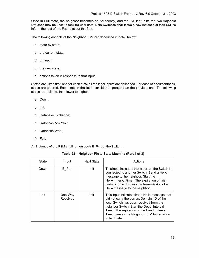
Project 1508-D Switch Fabric - 3 Rev 6.5 October 31, 2003
Once in Full state, the neighbor becomes an Adjacency, and the ISL that joins the two AdjacentSwitches may be used to forward user data. Both Switches shall issue a new instance of their LSR toinform the rest of the Fabric about this fact.
The following aspects of the Neighbor FSM are described in detail below:
a) state by state;
b) the current state;
c) an input;
d) the new state;
e) actions taken in response to that input.
States are listed first, and for each state all the legal inputs are described. For ease of documentation,states are ordered. Each state in the list is considered greater than the previous one. The followingstates are defined, from lower to higher:
a) Down;
b) Init;
c) Database Exchange;
d) Database Ack Wait;
e) Database Wait;
f) Full.
An instance of the FSM shall run on each E_Port of the Switch.
Table 93 – Neighbor Finite State Machine (Part 1 of 3)
State Input Next State Actions
Down E_Port Init This input indicates that a port on the Switch is connected to another Switch. Send a Hello message to the neighbor. Start the Hello_Interval timer. The expiration of this periodic timer triggers the transmission of a Hello message to the neighbor.
Init One-Way Received
Init This input indicates that a Hello message that did not carry the correct Domain_ID of the local Switch has been received from the neighbor Switch. Start the Dead_Interval Timer. The expiration of the Dead_Interval Timer causes the Neighbor FSM to transition to Init State.
131

Project 1508-D Switch Fabric - 3 Rev 6.5 October 31, 2003
Init Two-Way Received
Database Exchange
This input indicates that a Hello message car-rying both the remote and the local Domain_ID has been received from the neigh-bor Switch. Send the topology database to the neighbor. The database may be sent in multi-ple frames, and even in multiple Fibre Chan-nel Sequences. Restart the Dead_Interval Timer.
Database Exchange
Database Received
Database Ack Wait
This input indicates that an LSU with the Data-base Complete flag set has been received from the neighbor Switch. No action neces-sary, just a state transition.
Database Exchange
Database Sent Database Exchange
This input indicates that all the Link State Records that describe the topology database have been sent to the neighbor. Send an LSU to the neighbor with no LSRs and the Data-base Complete flag set.
Database Exchange
Database Acked
Database Wait
This input indicates that an LSA with the Data-base Complete flag set has been received from the neighbor Switch. No action neces-sary, just a state transition.
Database Ack Wait
Database Sent Database Ack Wait
This input indicates that all the Link State Records that describe the topology database have been sent to the neighbor. Send an LSU to the neighbor with no LSRs and the Data-base Complete flag set.
Database Ack Wait
Database Acked
Full This input indicates that an LSA with the Data-base Complete flag set has been received from the neighbor Switch. Issue a new instance of the LSR, to reflect the new Adja-cency. Compute the paths to all the Switches and program the routing tables.
Database Wait
Database Received
Full This input indicates that an LSU with the Data-base Complete flag set has been received from the neighbor Switch. Issue a new instance of the LSR, to reflect the new Adja-cency. Compute the paths to all the Switches and program the routing tables.
Any state except Down
and Init
Two-Way Received
Same state This input indicates that a Hello message car-rying both the remote and the local Domain_ID has been received from the neigh-bor Switch. This is a normal periodic Hello message received from the neighbor. Restart the Dead_Interval Timer.
Table 93 – Neighbor Finite State Machine (Part 2 of 3)
State Input Next State Actions
132

Project 1508-D Switch Fabric - 3 Rev 6.5 October 31, 2003
Figure 21 is a pictorial representation of the FSM where only the major state transitions are represent-ed.
Any state except Down
and Init
One-Way Received
Init This input indicates that a Hello message that did not carry the correct Domain_ID of the local Switch has been received from the neighbor Switch. The retransmission lists shall be emptied, and all the timers associated with the retransmission lists shall be stopped.
Any state Port Offline Down This input indicates that a port went offline. All the data structures related to the neighbor shall be removed. The retransmission lists shall be emptied, and all the timers associated with the neighbor shall be stopped. These include the retransmission timers, the Hello_Interval Timer and the Dead_Interval Timer. The same port may come back con-nected to a different Switch, or even as an F_Port, in which case the Neighbor FSM does not run. Issue a new instance of the LSR, that excludes this neighbor, to reflect the removal of an Adjacency.
Any state except Down
Hello_Interval Same state This input indicates that the Hello_Interval Timer has expired. Send a Hello message to the neighbor. In Down state Hello messages shall not be sent.
Any state except Down
Hello_Dead_Interval
Init This input indicates that the Dead_Interval Timer has expired. The port is still in E_Port state, but the local Switch has not received Hello messages from the neighbor. Re-initial-ize the data structures associated with the neighbor. Stop the Dead_Interval Timer. Issue a new instance of the LSR, that excludes this neighbor, to reflect the removal of an Adja-cency.
Full Initial DatabaseReceived
Init This input indicates that an LSU with the Initial Database Exchange flag set has been received from the neighbor Switch. Go into Init state and send One-Way Hellos.
Table 93 – Neighbor Finite State Machine (Part 3 of 3)
State Input Next State Actions
133

Project 1508-D Switch Fabric - 3 Rev 6.5 October 31, 2003
Figure 21 – Neighbor Finite State Machine
8.8 FSPF-Backbone
8.8.1 FSPF-Backbone Overview
The FSPF-Backbone runs the FSPF-Backbone routing protocol. The FSPF-Backbone routing protocolis the same as the FSPF protocol, as defined in 8.1 through 8.7, but exchanges Summary DescriptorLSRs. Clause 6.1 describes the SW_ILS used with the FSPF protocol with additional support for theFSPF-Backbone routing. A Border Switch (BSW) provides the connectivity between an AR and theFSPF-Backbone network. The BSW originates a Summary Descriptor LSR for its associated non-zeroAR and floods this summary on the FSPF-Backbone. A BSW receiving this Summary Descriptor LSRoriginates Link Descriptor LSRs extracted from the Summary LSR to its associated AR. BSWs are theonly Switches that originate or receive Summary Descriptor LSRs.
Figure 22 illustrates the architecture of the FSPF-Backbone Fabric and the corresponding backbonefor a small number of ARs. The FSPF-Backbone belongs to a special Autonomous Region called AR0,that utilizes the FSPF-Backbone routing protocol. The FSPF-Backbone consists of a physically con-tiguous arbitrary network topology of one or more Border Switches (BSW) and possibly Intra-AR0(ISW-0) Switches inter-connected by E_Ports. A Switch that may support at least one E_Port withFSPF-Backbone routing capability is capable of attaching to the FSPF-Backbone network. The FSPF-Backbone architecture defines three types of Switches:
a) Border Switches (BSW) - those Switches that connect an AR to the FSPF-Backbone;
b) Internal AR Switches (ISW) - those Switches that are internal to an AR;
Down
Init Exchange
DB wait
Full
Port up
Two-way received
Database received
Database acked
Database acked
Database received
DB ack wait
134

Project 1508-D Switch Fabric - 3 Rev 6.5 October 31, 2003
c) ISW-0 Switch is an AR0 Internal Switch that connects to BSWs, or to other ISW-0s. This Switchshall only communicate path information using the Summary Record format of the Link-StateRecord.
Figure 22 – FSPF-Backbone Architecture
Figure 23 shows the FSPF-Backbone consisting of point-to-point links and FC-BBW WAN interfacesthat serve to extend the point-to-point connectivity between two BSWs across a non-Fibre Channelnetwork.
Figure 23 – Point-to-point FSPF-Backbone Links
Figure 24 shows two ISW-0 Switches connecting BSW Switches.
FSPF-Backbone
E_Port
E_Port
AR0
E_Port
E_Port
AR 2AR 1
AR 4AR 3
E_PortE_Port
E_Port
E_Port
BSW
BSW BSW
BSW
ISW
ISWISW
ISW
E_Port
E_Port
BSW
BSWE_Port
AR 2AR 1
AR 4AR 3
E_Port
WANFSPF-Backbone
BSW
FC-BBW
BSW
FC-BBWB_Port
E_Port
B_Port
E_Port
ISL
135

Project 1508-D Switch Fabric - 3 Rev 6.5 October 31, 2003
Figure 24 – AR0 Consisting of Two ISW-0 Switching Devices
A Switch that connects BSWs and supports any internal service (e.g., Extended Copy) that requires aDomain_ID is a BSW Switch. Figure 25 shows an example of such a configuration. Note that a well-known service such as a Name Server, does not constitute an internal service and such services maybe supported in the ISW-0. It is expected that the total number of Switches (BSWs and ISW-0s) shouldbe small in any real implementation. Therefore assignment of Domain_IDs to the AR0 Switches maybe manually configured.
Figure 25 – Internal Service Supported By a BSW
The Summary LSR provides information on the Fibre Channel Address Domains supported by an AR.A Domain_ID conflict occurs whenever the same Domain Address is reported in two (or more) LSAsoriginating from different ARs. All Border Switches (BSW) and ISW-0 Switches shall be required to runa check against such a conflict every time they receive an LSA. All BSWs shall refrain from routingdata frames for the conflicting Domain_IDs, until such time that a new LSA is issued without a conflict.
BSW
E_Port
E_PortE_Port
E_Port
AR 1
AR 4AR 3
AR 2
AR0
ISW-0
FSPF-Backbone
E_Port
E_Port
E_Port
E_Port
E_Port
BSW BSW
BSW
E_PortISW-0
BSW
AR 1
AR 4AR 3
AR 2
AR0FSPF-Backbone
BSW
BSW
BSW
BSW
AR 5Internal Service
136

Project 1508-D Switch Fabric - 3 Rev 6.5 October 31, 2003
8.8.2 Multiple Switch Connections
Multiple BSWs from the same AR may connect to the FSPF-Backbone, with the requirement that phys-ical contiguity be always maintained with the FSPF-Backbone. Figure 26 shows a dual BSW connec-tion to the FSPF-Backbone. Illustrative examples of allowed and disallowed dual BSW connectivity areshown in figure 27 and figure 28. The example in figure 28 is disallowed because the FSPF-Backboneis physically discontiguous resulting in two disjoint FSPF-Backbones. In figure 27 and figure 28 notethat an internal connection between two BSWs is allowed but not necessarily part of the FSPF-Back-bone. Two E_Ports supporting FSPF-Backbone on two separate BSWs belonging to the same AR,may be connected by one or more links.
Figure 26 – Dual BSW connectivity
Figure 27 – Physically Contiguous FSPF-Backbone with dual BSWs (Allowed)
E_Port
E_Port
AR 3
AR 2AR 1
E_Port
BSW BSWE_Port
E_Port E_Port
This link is allowed but not part of FSPF-Backbone
BSW
BSW
FSPF-BackboneAR0
E_Port
E_Port
AR 3
AR 2AR 1
E_Port
BSW
BSW
BSW BSWE_Port E_PortE_Port
E_Port E_Port
This link is allowed but not part of FSPF-Backbone
FSPF-BackboneAR0
137
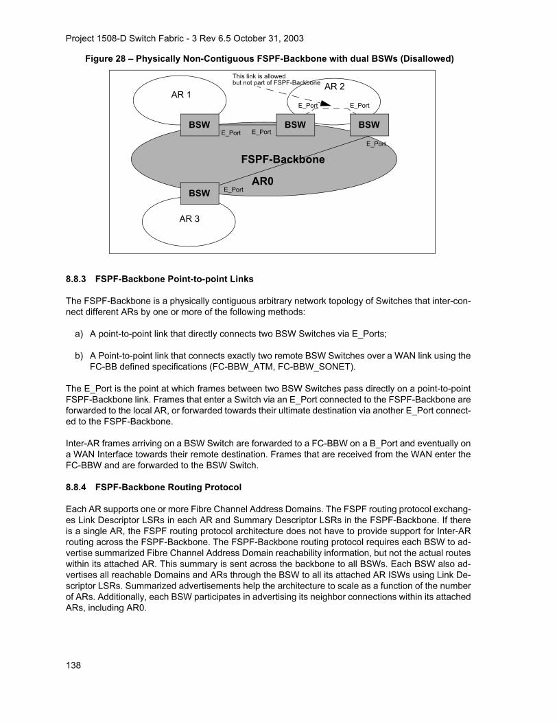
Project 1508-D Switch Fabric - 3 Rev 6.5 October 31, 2003
Figure 28 – Physically Non-Contiguous FSPF-Backbone with dual BSWs (Disallowed)
8.8.3 FSPF-Backbone Point-to-point Links
The FSPF-Backbone is a physically contiguous arbitrary network topology of Switches that inter-con-nect different ARs by one or more of the following methods:
a) A point-to-point link that directly connects two BSW Switches via E_Ports;
b) A Point-to-point link that connects exactly two remote BSW Switches over a WAN link using theFC-BB defined specifications (FC-BBW_ATM, FC-BBW_SONET).
The E_Port is the point at which frames between two BSW Switches pass directly on a point-to-pointFSPF-Backbone link. Frames that enter a Switch via an E_Port connected to the FSPF-Backbone areforwarded to the local AR, or forwarded towards their ultimate destination via another E_Port connect-ed to the FSPF-Backbone.
Inter-AR frames arriving on a BSW Switch are forwarded to a FC-BBW on a B_Port and eventually ona WAN Interface towards their remote destination. Frames that are received from the WAN enter theFC-BBW and are forwarded to the BSW Switch.
8.8.4 FSPF-Backbone Routing Protocol
Each AR supports one or more Fibre Channel Address Domains. The FSPF routing protocol exchang-es Link Descriptor LSRs in each AR and Summary Descriptor LSRs in the FSPF-Backbone. If thereis a single AR, the FSPF routing protocol architecture does not have to provide support for Inter-ARrouting across the FSPF-Backbone. The FSPF-Backbone routing protocol requires each BSW to ad-vertise summarized Fibre Channel Address Domain reachability information, but not the actual routeswithin its attached AR. This summary is sent across the backbone to all BSWs. Each BSW also ad-vertises all reachable Domains and ARs through the BSW to all its attached AR ISWs using Link De-scriptor LSRs. Summarized advertisements help the architecture to scale as a function of the numberof ARs. Additionally, each BSW participates in advertising its neighbor connections within its attachedARs, including AR0.
E_Port
E_Port
AR 3
AR 2AR 1
E_Port
BSW
BSW
BSW BSWE_Port
E_Port E_Port
This link is allowed but not part of FSPF-Backbone
FSPF-Backbone
AR0
138

Project 1508-D Switch Fabric - 3 Rev 6.5 October 31, 2003
Figure 29 shows a FSPF-backbone connection with internal Switch connections. In this diagram, thefollowing LSRs are be distributed:
a) BSW 1 sends a Summary LSR to BSW 2 that contains the path costs to reach Domain 1, Do-main 2, and Domain 3. This path cost comes from BSW 1 running its path selection algorithmon the LSRs that it received from its neighbor Switches.
b) BSW 2 sends a Summary LSR to BSW 1 that contains the path costs to reach Domain 4, Do-main 5, Domain 6, and the Summary LSR from BSW 3. The path cost for Domain 4, Domain 5,and Domain 6 comes from BSW 2 running its path selection algorithm on the LSRs that it re-ceived from its neighbor Switch. The Summary LSR forwarded from BSW 3 shall incorporatethe path cost between BSW 3 and BSW 2.
c) BSW 3 sends a Summary LSR to BSW 2 that contains the path costs to reach Domain 7, Do-main 8, and Domain 9. This path cost comes from BSW 3 running its path selection algorithmon the LSRs that it received from its neighbor Switch.
d) BSW 1 sends Link Descriptor LSRs to neighbor Switches Domain 1 and Domain 3, that de-scribe virtual connections to Domain 4, Domain 5, Domain 6, Domain 7, Domain 8, and Domain9. These LSRs contain the path cost that came in the Summary LSR from BSW 2 plus the costof the link from BSW 1 to BSW 2.
e) BSW 2 sends Link Descriptor LSRs to neighbor Switch Domain 4, that describe virtual connec-tions to Domain 1, Domain 2, Domain 3, Domain 7, Domain 8, and Domain 9. These LSRs con-tain the path cost that came in the Summary LSRs from BSW 1 and BSW 3 plus the cost of thelink from BSW 2 to BSW 1.
If an Autonomous Region has 2 BSWs, they shall not forward Summary LSRs that came from the localAutonomous region, and frames destined to the local Autonomous Region shall not traverse theFSPF-Backbone.
Figure 29 – FSPF-Backbone Routing Protocol Overview.
FSPF-BackboneE_Port
AR0
AR 1
AR 3
E_PortBSW 1
BSW 2
Domain 1
Domain 2
Domain 3
Domain 6
Domain 4
Domain 5
BSW 3
Domain 9
Domain 7
Domain 8
E_Port
E_Port
139

Project 1508-D Switch Fabric - 3 Rev 6.5 October 31, 2003
9 Distributed Services
9.1 Basic Model
A distributed services model is used to allow a Fabric to provide consistent services to all attachedN_Ports. This Standard defines a common framework by which all Distributed Services communicate.Specific mappings onto this framework are also specified for the distributed Name Server and the dis-tributed Management Server. Please note that in the following discussion it is convenient to say thata server is “contained” within a Switch. In this case the term “contain” does not imply that an entity isphysically inside the Switch; it may be physically outside the Switch, and still operate as described be-low.
9.2 Distributed Services Framework
9.2.1 Goals and Characteristics of the Distributed Services Framework
All Distributed Services are mapped onto a common framework. The goal of this framework is three-fold:
a) Define a consistent method for distributing services across Switches in a Fabric;
b) Define a distribution method that is topology independent;
c) Define a method that preserves processing facilities for existing frame formats.
In order to accomplish these goals this standard defines the following Distributed Server characteris-tics:
a) Transport;
b) Common Characteristics;
c) Work categories;
d) Frame formats.
9.2.2 Distributed Service Transport
9.2.2.1 Required FC-2 Parameters
Generic Service requests and responses are transported between Distributed Servers using the Com-mon Transport (FC-CT) defined by FC-GS-4.
All CT frames shall be transmitted using the FT_1 frame format via the Class F service. The followingdefines the FC-2 header fields of all Distributed Services frames:
R_CTL: This field shall be set to 02h for all request frames, and to 03h for all reply frames.
CS_CTL: This field shall be set to 00h.
D_ID: This field shall be set to the Domain Controller Identifier of the destination Switch.
S_ID: This field shall be set to the Domain Controller Identifier of the source Switch.
140

Project 1508-D Switch Fabric - 3 Rev 6.5 October 31, 2003
TYPE: This field shall be set to 20h, indicating Fibre Channel Fabric Generic Services.
Each request shall be the first Sequence of an Exchange and the associated response shall be thelast Sequence of the same Exchange. All other fields shall be set as appropriate according to the rulesdefined in FC-FS.
9.2.2.2 FC-CT Header Usage
The following values shall be set in the FC-CT Header for all Distributed Services requests and re-sponses:
FC-CT revision: 01h
IN_ID: The value of IN_ID in a Switch related request shall be preserved in all responses to that re-quest. This only applies to an IN_ID value set by the Entry Switch.
Options: The X_Bit shall be set to 0 to indicate a single bidirectional exchange per request/response.The Partial Response bit shall be set to zero in Switch-to-Switch requests.
NOTE 36 – Multiple requests/responses may be active using multiple bidirectional exchanges between anypair of Switches.
9.2.2.3 Frame Distribution
It is important to note that for a Distributed Services request, a remote Switch shall never send a re-sponse directly to the requesting Nx_Port. All responses shall be sent to the Entry Switch. It is the re-sponsibility of the Entry Switch to send the appropriate response to the requesting Nx_Port.
Furthermore, an Nx_Port shall always communicate to a Distributed Service via it’s well known ad-dress and Nx_Ports shall not send Distributed Service requests to Domain Controllers. In addition,Distributed Services request and responses are transported only between Switches and not betweena Switch and an Nx_Port.
9.2.3 Common Characteristics
Each Distributed Service shares a set of common characteristics. These characteristics shall be de-fined as follows:
a) Timeouts: For requests between Switches, the time-out value shall be D_S_TOV.
b) Local Data Copies: Local data copies may be optionally allowed by a Distributed Service. If aDistributed Service allows local data copies it shall also specify the method by which the integ-rity of the local copied data is maintained.
c) Exchange Management: Each request between Switches shall be mapped to a unique ex-change. Multiple outstanding requests are allowed between a pair of Switches up to the end-to-end credit resources specified by the receiving Switch.
d) Responses: Each request sent shall receive a response. If the receiving Switch does not havethe requested data, then it shall respond with an LS_RJT (reason code 09h “Unable to performcommand request”, reason code explanation 2Ah “Unable to supply requested data”). If a re-sponse is not received from all Switches to which a request was sent within the time-out period,then the request shall be considered partial and a response sent back to the Nx_Port as appro-priate for the Service.
141

Project 1508-D Switch Fabric - 3 Rev 6.5 October 31, 2003
e) Partial Response: For many requests even a partial response to the requesting Nx_Port is use-ful. A partial response may occur for a number of reasons: 1) one of the Switches a request isdirected to is busy and unable to respond within the time-out period, 2) one of the Switches arequest is directed to does not support the service requested. A service may allow partial re-sponses for a subset of its requests. If the response to a request is partial, the service shall setthe partial response bit in the CT Header of the response back to the Nx_Port. This notifies theNx_Port that the data in the response may not be complete.
f) Data Merge: Describes how data from multiple responses is consolidated.
g) Error Recovery: If an error on a Distributed Services frame is detected (e.g., No ACK, P_BSY),the frame may be retransmitted up to D_S_TOV.
9.2.4 Zoning Considerations
If Zoning is present in a Fabric, Distributed Services may be affected. The following rules shall applyfor Zoning with regard to Distributed Services:
a) Switch-to-Switch communications shall not be zoned. This only applies to the Class F CTHeader based Distributed Services frames;
b) Zoning is applied by the Entry Switch. If a particular Distributed Service is affected by Zoning, itis the responsibility of the Entry Switch to make sure that a requesting Nx_Port does not re-ceive data for that Distributed Service that is outside of the Nx_Port’s Zone.
9.2.5 Work Categories
Work categories are definitions that allow consistent mapping of services to Distributed Services.These categories define how each Distributed Service maps its commands given the Distribution char-acteristic:
The work categories are defined below:
Local
Local requests are those that may be handled entirely by the Entry Switch. A request is local for thefollowing reasons:
a) The data being requested is owned entirely by the Entry Switch. This situation would be depen-dant on the type of request;
b) The Entry Switch is maintaining a local copy of the data being requested. This situation mayoccur for any request depending on the local data copy rules of the Distributed Service to whichthe request belongs.
Any request that is determined to be local shall be processed as appropriate for the service as definedin FC-GS-4.
1-to-1
A 1-to-1 request is a request that is unable to be handled entirely by the Entry Switch, but for whichthe Entry Switch has identified a single remote Switch that may handle the request. The local Switchsends the request frame directly to the Domain Controller of remote Switch.
142

Project 1508-D Switch Fabric - 3 Rev 6.5 October 31, 2003
1-to-Many
A 1-to-Many request is a request that is unable to be handled entirely by the Entry Switch, but for whichthe Entry Switch has identified multiple remote Switches that may handle the request. The local Switchsends request frames directly to the Domain Controller of all remote Switches that it has identified tocontain requested data.
1-to-All
A 1-to-All request is a request that is unable to be handled entirely by the Entry Switch, but for whichthe Entry Switch is unable to identify the set of remote Switches to query. The Entry Switch sends re-quest frames directly to the Domain Controller of all Switches in the Fabric.
9.2.6 Frame Formats
Where possible Distributed Services should use the same frame formats for Switch-to-Switch commu-nications as are used for Nx_Port requests.
9.2.7 FC-CT Command Restrictions
To avoid overlap of command codes associated with FC-CT commands originated external to the Fab-ric with FC-CT commands originated internal to the Fabric, the following FC-CT command codes shallnot be used by any well-known server for the FC-GS-4 client/server interface.
Command codes 0400h-04FFh and E000h-EFFFh: Fabric Internal FC-CT Commands;
Command codes F000h-FFFFh: Vendor specific FC-CT Commands.
9.3 Distributed Name Server
9.3.1 General Behavior
The distributed Name Service is provided as follows:
a) Each Switch contains its own resident Name Server, called a distributed Name Server (dNS);
b) Each dNS within a Switch is responsible for the name entries associated with the Domain(s)assigned to the Switch;
c) Each dNS within a Switch shall only return information associated with the Domain(s)) forwhich the Switch is responsible;
d) A client Nx_Port communicates its Name Service request (as defined in FC-GS-4) to the EntrySwitch via the well-known address;
e) The dNS within the local Switch services the request by making any needed requests of otherdNS’s contained by the other Switches, if the required information is not available locally;
f) A dNS may maintain local data copies. Integrity of locally copied data is maintained viaSW_RSCN notification. This implies that all Switches shall distribute SW_RSCN notificationthroughout the Fabric whenever a change takes place in their local dNS database;
g) The communication between dNS’s to acquire the requested information is transparent to theoriginal requesting client;
143

Project 1508-D Switch Fabric - 3 Rev 6.5 October 31, 2003
h) Partial responses to dNS queries are allowed. If an Entry Switch sends a partial response backto an Nx_Port it shall set the partial response bit in the CT Header.
9.3.2 FC-CT for Distributed Name Servers
9.3.2.1 dNS Command Codes
The Command Codes for FC-CT requests defined for dNS use are summarized in table 94. Codes0100h - 0300h shall be as defined in FC-GS-4. All other requests are defined below. The format of theEntry field used in the following commands follow the Name Server Entry format described in 9.3.3.
Table 94 – FC-CT Command Codes for dNS (Part 1 of 4)Encoded Value
(hex) Description MnemonicWork
CategoryPayload
Defined in Notes
0100 Get all next GA_NXT 1-to-All FC-GS-4
0101 Get Identifiers According to Scope GID_A 1-to-1 or1-to-Many
FC-GS-4 a
0112 Get Port_Name, based on Port Identifier
GPN_ID 1-to-1 FC-GS-4
0113 Get Node_Name, based on Port Identifier
GNN_ID 1-to-1 FC-GS-4
0114 Get Class of Service, based on Port Identifier
GCS_ID 1-to-1 FC-GS-4
0117 Get FC-4 TYPEs, based on Port Identifier
GFT_ID 1-to-1 FC-GS-4
0118 Get Symbolic Port_Name, based on Port Identifier
GSPN_ID 1-to-1 FC-GS-4
011A Get Port Type, based on Port Identifier
GPT_ID 1-to-1 FC-GS-4
011B Get Port IP Address, based on Port Identifier
GIPP_ID 1-to-1 FC-GS-4
011C Get Fabric Port_Name, based on Port Identifier
GFPN_ID 1-to-1 FC-GS-4
011D Get Hard Address, based on Port Identifier
GHA_ID 1-to-1 FC-GS-4
a The GID_A request may either be 1-to-1 or 1-to-Many depending on the format of the request.
b Registration requests may be distributed if performed by a third party. Otherwise, they are local andoutside the scope of this document.
c De-registration requests may be distributed if performed by a third party. Otherwise, they are local andoutside the scope of this document.
d Work Categories for Name Server Entry Object requests are at the discretion of the originating Switch.
144

Project 1508-D Switch Fabric - 3 Rev 6.5 October 31, 2003
011E Get FC-4 Descriptors - Port Identifier
GFD_ID 1-to-1 FC-GS-4
011F Get FC-4 Features - Port Identifier GFF_ID 1-to-1 FC-GS-4
0121 Get Port Identifier, based on Port_Name
GID_PN 1-to-All FC-GS-4
012B Get Port IP Address, based on Port_Name
GIPP_PN 1-to-All FC-GS-4
0131 Get Port Identifier, based on Node_Name
GID_NN 1-to-All FC-GS-4
0132 Get Port_Names based on Node_Name
GPN_NN 1-to-All FC-GS-4
0135 Get IP address, based on Node_Name
GIP_NN 1-to-All FC-GS-4
0136 Get Initial Process Associator, based on Node_Name
GIPA_NN 1-to-All FC-GS-4
0139 Get Symbolic Node_Name, based on Node_Name
GSNN_NN 1-to-All FC-GS-4
0153 Get Node_Name, based on IP address
GNN_IP 1-to-All FC-GS-4
0156 Get Initial Process Associator, based on IP address
GIPA_IP 1-to-All FC-GS-4
0171 Get Port Identifiers, based on FC-4 TYPE
GID_FT 1-to-All FC-GS-4
0172 Get Port_Names, based on FC-4 TYPE
GPN_FT 1-to-All FC-GS-4
0173 Get Node_Names, based on FC-4 TYPE
GNN_FT 1-to-All FC-GS-4
01A1 Get Port Identifiers, based on Port Type
GID_PT 1-to-All FC-GS-4
Table 94 – FC-CT Command Codes for dNS (Part 2 of 4)Encoded Value
(hex) Description MnemonicWork
CategoryPayload
Defined in Notes
a The GID_A request may either be 1-to-1 or 1-to-Many depending on the format of the request.
b Registration requests may be distributed if performed by a third party. Otherwise, they are local andoutside the scope of this document.
c De-registration requests may be distributed if performed by a third party. Otherwise, they are local andoutside the scope of this document.
d Work Categories for Name Server Entry Object requests are at the discretion of the originating Switch.
145

Project 1508-D Switch Fabric - 3 Rev 6.5 October 31, 2003
01B1 Get Port Identifiers, based on Port IP Address
GID_IPP 1-to-All FC-GS-4
01B2 Get Port_Name, based on Port IP Address
GPN_IPP 1-to-All FC-GS-4
01C1 Get Port Identifiers, based on Fabric Port_Name
GID_FPN 1-to-All FC-GS-4
01D1 Get Permanent Port_Name GPPN_ID 1-to-All FC-GS-4
01F1 Get Port Identfiers, based on FC-4 Features
GID_FF 1-to-All FC-GS-4
0212 Register Port_Name RPN_ID 1-to-1 FC-GS-4 b
0213 Register Node_Name RNN_ID 1-to-1 FC-GS-4 b
0214 Register Class of Service RCS_ID 1-to-1 FC-GS-4 b
0217 Register FC-4 TYPEs RFT_ID 1-to-1 FC-GS-4 b
0218 Register Symbolic Port_Name RSPN_ID 1-to-1 FC-GS-4 b
021A Register Port Type RPT_ID 1-to-1 FC-GS-4 b
021B Register IP Address (Port) - Port Identifier
RIPP_ID 1-to-1 FC-GS-4 b
021D Register Hard Address - Port Identifier
RHA_ID 1-to-1 FC-GS-4 b
021E Register FC-4 Descriptors - Port Identifier
RFD_ID 1-to-1 FC-GS-4 b
021F Register FC-4 Features - Port Identifier
RFF_ID 1-to-1 FC-GS-4 b
0235 Register IP Address (Node) RIP_NN 1-to-All FC-GS-4 b
0236 Register Initial Process Associator RIPA_NN 1-to-All FC-GS-4 b
Table 94 – FC-CT Command Codes for dNS (Part 3 of 4)Encoded Value
(hex) Description MnemonicWork
CategoryPayload
Defined in Notes
a The GID_A request may either be 1-to-1 or 1-to-Many depending on the format of the request.
b Registration requests may be distributed if performed by a third party. Otherwise, they are local andoutside the scope of this document.
c De-registration requests may be distributed if performed by a third party. Otherwise, they are local andoutside the scope of this document.
d Work Categories for Name Server Entry Object requests are at the discretion of the originating Switch.
146

Project 1508-D Switch Fabric - 3 Rev 6.5 October 31, 2003
0239 Register Symbolic Node_Name RSNN_NN 1-to-All FC-GS-4 b
0300 De-register all DA_ID 1-to-1 FC-GS-4 c
0410 Get Entry, based on Port Identifier GE_ID Any FC-SW-3 d
0420 Get Entry, based on Port_Name GE_PN Any FC-SW-3 d
0430 Get Entries, based on Node_Name
GE_NN Any FC-SW-3 d
0450 Get Entries, based on IP address GE_IP Any FC-SW-3 d
0470 Get Entries, based on FC-4 TYPE GE_FT Any FC-SW-3 d
04A0 Get Entries, based on Port Type GE_PT Any FC-SW-3 d
04B0 Get Entries, based on Zone Member
GE_ZM Any FC-SW-3
04C0 Get Entries, Based on Zone Name GE_ZN Any FC-SW-3
04D0 Get Entries, Based on Port IP Address
GE_IPP Any FC-SW-3
04E0 Get Entries, Based on FC-4 Features
GE_FF Any FC-SW-3
04F0 Get Entries, Based on Fabric Port_Name
GE_FPN Any FC-SW-3
0500 Remove All RA 1-to-1 FC-SW-3
8001 Reject CT_IU CT_RJT 1-to-1 FC-GS-4
8002 Accept CT_IU CT_ACC 1-to-1 FC-GS-4
Table 94 – FC-CT Command Codes for dNS (Part 4 of 4)Encoded Value
(hex) Description MnemonicWork
CategoryPayload
Defined in Notes
a The GID_A request may either be 1-to-1 or 1-to-Many depending on the format of the request.
b Registration requests may be distributed if performed by a third party. Otherwise, they are local andoutside the scope of this document.
c De-registration requests may be distributed if performed by a third party. Otherwise, they are local andoutside the scope of this document.
d Work Categories for Name Server Entry Object requests are at the discretion of the originating Switch.
147

Project 1508-D Switch Fabric - 3 Rev 6.5 October 31, 2003
9.3.2.2 FC-CT Header usage for dNS
The following FC-CT Header parameters, beyond those defined in 9.2.2.2, shall be used for dNSframes:
GS_Type: FCh (Directory Service application);
GS_Subtype: 02h (Name Service);
Command Code: see table 94.
9.3.3 Name Server Objects
The Name Server Objects communicated between distributed Name Servers using FC-CT are as de-fined in FC-GS-4 with no modification, but with several additions. The format of a Name Server EntryObject is as shown in table 95.
Table 95 – Name Server Entry Object (Part 1 of 2)
Mandatory ItemSize
Bytes Comments
Yes Entry Object Format Indicator 1
Yes Owner Identifier 3
Yes Port Type 1
Yes N_Port_ID 3
Yes N_Port_Name 8
No Port Symbolic Name 256 a
Yes Node_Name 8
No Node Symbolic Name 256 a
Yes Initial Process Associator 8
Yes IP address (Node) 16
Yes Class of Service 4
Yes FC-4 TYPEs 32
Yes IP Address (Port) 16
a This field is not present in the Small Name Server Entry Object.
b This field is not present in the Large or Small Name Server Entry Objects.
c See table 96 for the description of the FC-4 Descriptor as it relates to the Name Serv-er Entry object.
148

Project 1508-D Switch Fabric - 3 Rev 6.5 October 31, 2003
All fields shall be fixed length as indicated in the table 95. The Owner Identifier shall be the DomainController Identifier for the Switch that owns this Entry. All other fields shall be formatted as defined inFC-GS-4.
The format of the FC-4 Descriptor as it relates to the Name Server Entry object is depicted in table 96below:
FC-4 Type: This field indicates the FC-4 Type for which the FC-4 Descriptor is associated.
Number of FC-4 Descriptor Types Registered: This field indicates the total number of FC-4 TypeDescriptors registered.
FC-4 Descriptor Length and FC-4 Descriptor: Follows the format of the FC-4 Descriptor describedin FC-GS-4.
Yes F_Port_Name 8
Yes Reserved 1
Yes Hard Address 3
No FC-4 Features 128 b
No FC-4 Descriptor 260 b and c
Table 96 – FC-4 Descriptor Format for Name Server Object
Item SizeBytes Notes
FC-4 Type 1
Number of FC-4 Descriptor Types Registered 1
Reserved 2
FC-4 Descriptor length 1
FC-4 Descriptor 255 a
a For use in the Name Server Object, this field is always a fixedlength of 255 bytes, even though the contents may have a differ-ent length.
Table 95 – Name Server Entry Object (Part 2 of 2)
Mandatory ItemSize
Bytes Comments
a This field is not present in the Small Name Server Entry Object.
b This field is not present in the Large or Small Name Server Entry Objects.
c See table 96 for the description of the FC-4 Descriptor as it relates to the Name Serv-er Entry object.
149

Project 1508-D Switch Fabric - 3 Rev 6.5 October 31, 2003
The rules associated with the FC-4 Descriptor are listed below:
a) If more than one FC-4 Descriptor is registered per port being returned, then only a single FC-4Descriptor shall be returned in the Name Server Object in the response;
b) If more than one FC-4 Descriptor is registered per port, the determination of which single FC-4Descriptor is returned in the Name Server Object is outside the scope of this document;
c) If more than one FC-4 Descriptor is registered for the responding port, the remaining FC-4 De-scriptors may be accessed via Name Server to Name Server requests specific to FC-4 De-scriptors (e.g., GFD_ID).
The Entry Object Format Indicator is depicted in table 97.
The sizes of the Name Server Entry Object is depicted in table 98.
The normal response to Get Entry requests in a distributed Name Server model returns one or moreName Server Entry Objects.
When a response to a request contains either a Port Symbolic Name or Node Symbolic Name that isgreater than zero in length, and does not contain an FC-4 Descriptor or FC-4 Features, the NameServer Entry Object with an Entry Object Format Indicator of 00h shall be used by the responder.
The responder may return the Name Server Entry Object with an Entry Object Format Indicator of 01hif neither a Port Symbolic Name, Node Symbolic Name, or FC-4 Descriptor is registered for the portand would result in those Name Server Objects being of length zero, and FC-4 Features have not beenregistered for the port.
Table 97 – Entry Object Format IndicatorBit Description (Bit Value=1)
0 The Port Symbolic Name and Node Symbolic Name are not included in the Entry Object
1 The FC-4 Features and FC-4 Descriptor fields are Included in the Entry Object
2-7 Reserved
Table 98 – Name Server Entry Object DescriptionValue (Hex)
Length (Bytes) Description
00 624 Large Name Server Entry Object
01 112 Small Name Server Entry Object
02 1012 Large Name Server Entry Object + FC-4 Features + FC-4 Descriptor
03 500 Small Name Server Entry Object + FC-4 Features + FC-4 Descriptor
150

Project 1508-D Switch Fabric - 3 Rev 6.5 October 31, 2003
When a response to a request contains either a Port Symbolic Name or Node Symbolic Name that isgreater than zero in length, and contains an FC-4 Descriptor or FC-4 Features, the Name Server EntryObject with an Entry Object Format Indicator of 02h shall be used by the responder.
The responder shall return the Name Server Entry Object with an Entry Object Format Indicator of 03hif it would contain an FC-4 Descriptor or FC-4 Features, and does not contain a Port Symbolic Nameor Node Symbolic Name.
9.3.4 FC-CT requests for dNS
9.3.4.1 Remove All
The Remove All shall be used to delete all locally copied Entries in the database of another dNS for agiven Port Identifier. A dNS should issue an RA request only if the associated Port Identifier is removedor has disappeared from the Fabric, or if the Port Identifier has been reused.
The dNS shall accept RA requests received from any valid Domain Controller Identifier. The dNS mayreject an RA request from any other source.
The format of the RA request is shown in table 99.
The Port Identifier format shall be as defined in FC-GS-4. A dNS shall not reject an RA request if it hasno locally copied Entry associated with the Port Identifier.
The format of the RA reply is shown in table 100.
Table 99 – RA request payload
ItemSize
Bytes
FC-CT Header 16
Reserved 1
Port Identifier 3
Table 100 – RA Accept payload
ItemSize
Bytes
FC-CT Header 16
151

Project 1508-D Switch Fabric - 3 Rev 6.5 October 31, 2003
9.3.4.2 Get Entry based on Port Identifier
The dNS shall, when it receives a GE_ID request, return the Entry object for the specified Port Identi-fier. The format of the GE_ID request is shown in table 101.
The Port Identifier format shall be as defined in FC-GS-4. The dNS may reject a GE_ID request forreasons not specified in this document.
The format of the reply payload to a GE_ID request is shown in table 102.
Since this request returns only one Entry, the Number of Entries field shall always be set to one forthis reply. The Entry field shall contain the Entry for the requested Port Identifier.
9.3.4.3 Get Entry based on Port_Name
The dNS shall, when it receives a GE_PN request, return the Entry object for the specified Port_Name.The format of the GE_PN request is shown in table 103.
The Port_Name format shall be as defined in FC-GS-4. The dNS may reject a GE_PN request for rea-sons not specified in this document.
Table 101 – GE_ID request payload
ItemSize
Bytes
FC-CT Header 16
Reserved 1
Port Identifier 3
Table 102 – GE_ID Accept payload
ItemSize
Bytes
FC-CT Header 16
Number of Entries 4
Entry n
Table 103 – GE_PN request payload
ItemSize
Bytes
FC-CT Header 16
Port_Name 8
152

Project 1508-D Switch Fabric - 3 Rev 6.5 October 31, 2003
The format of the reply payload to a GE_PN request is shown in table 104.
Since this request returns only one Entry, the Number of Entries field shall always be set to one forthis reply. The Entry field shall contain the Entry for the requested Port_Name.
9.3.4.4 Get Entries based on Node_Name
The dNS shall, when it receives a GE_NN request, return the Entry object for the specifiedNode_Name. The format of the GE_NN request is shown in table 105.
The Node_Name format shall be as defined in FC-GS-4. The dNS may reject a GE_NN request forreasons not specified in this document.
The format of the reply payload to a GE_NN request is shown in table 106.
The Number of Entries field shall be set to the number of Entries returned. Each Entry field shall con-tain an Entry for the requested Node_Name.
Table 104 – GE_PN Accept payload
ItemSize
Bytes
FC-CT Header 16
Number of Entries 4
Entry n
Table 105 – GE_NN request payload
ItemSize
Bytes
FC-CT Header 16
Node_Name 8
Table 106 – GE_NN Accept payload
ItemSize
Bytes
FC-CT Header 16
Number of Entries 4
Entry 1 n
...
Entry N n
153

Project 1508-D Switch Fabric - 3 Rev 6.5 October 31, 2003
9.3.4.5 Get Entries based on IP address (Node)
The dNS shall, when it receives a GE_IP request, return the Entry object for the specified IP address.The format of the GE_IP request is shown in table 107.
The Node IP address format shall be as defined in FC-GS-4. The dNS may reject a GE_IP request forreasons not specified in this document.
The format of the reply payload to a GE_IP request is shown in table 108.
The Number of Entries field shall be set to the number of Entries returned. Each Entry field shall con-tain an Entry for the requested IP address.
9.3.4.6 Get Entries based on FC-4 TYPEs
The dNS shall, when it receives a GE_FT request, return the Entry object for the specified FC-4TYPEs; note that more than one FC-4 TYPE may be specified. The format of the GE_FT request isshown in table 109.
The FC-4 TYPE format shall be as defined in FC-GS-4. The dNS may reject a GE_FT request for rea-sons not specified in this document.
Table 107 – GE_IP request payload
ItemSize
Bytes
FC-CT Header 16
IP address (Node) 16
Table 108 – GE_IP Accept payload
ItemSize
Bytes
FC-CT Header 16
Number of Entries 4
Entry 1 n
...
Entry N n
Table 109 – GE_FT request payload
ItemSize
Bytes
FC-CT Header 16
FC-4 TYPEs 32
154

Project 1508-D Switch Fabric - 3 Rev 6.5 October 31, 2003
The format of the reply payload to a GE_FT request is shown in table 110.
The Number of Entries field shall be set to the number of Entries returned. Each Entry field shall con-tain an Entry for the requested FC-4 TYPEs.
9.3.4.7 Get Entries based on Port Type
The dNS shall, when it receives a GE_PT request, return the Entry object for the specified Port Type.The format of the GE_PT request is shown in table 111.
The Port Type format shall be as defined in FC-GS-4. The dNS may reject a GE_PT request for rea-sons not specified in this document.
Table 110 – GE_FT Accept payload
ItemSize
Bytes
FC-CT Header 16
Number of Entries 4
Entry 1 n
...
Entry N n
Table 111 – GE_PT request payload
ItemSize
Bytes
FC-CT Header 16
Reserved 3
Port Type 1
155
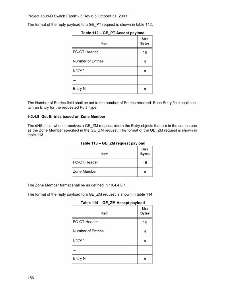
Project 1508-D Switch Fabric - 3 Rev 6.5 October 31, 2003
The format of the reply payload to a GE_PT request is shown in table 112.
The Number of Entries field shall be set to the number of Entries returned. Each Entry field shall con-tain an Entry for the requested Port Type.
9.3.4.8 Get Entries based on Zone Member
The dNS shall, when it receives a GE_ZM request, return the Entry objects that are in the same zoneas the Zone Member specified in the GE_ZM request. The format of the GE_ZM request is shown intable 113.
The Zone Member format shall be as defined in 10.4.4.6.1.
The format of the reply payload to a GE_ZM request is shown in table 114.
Table 112 – GE_PT Accept payload
ItemSize
Bytes
FC-CT Header 16
Number of Entries 4
Entry 1 n
...
Entry N n
Table 113 – GE_ZM request payload
ItemSize
Bytes
FC-CT Header 16
Zone Member n
Table 114 – GE_ZM Accept payload
ItemSize
Bytes
FC-CT Header 16
Number of Entries 4
Entry 1 n
...
Entry N n
156

Project 1508-D Switch Fabric - 3 Rev 6.5 October 31, 2003
The Number of Entries field shall be set to the number of Entries returned. Each Entry field shall con-tain an Entry for a Port that is in the same zone as the Zone Member specified in the GE_ZM request.Each Entry shall be only for ports local to the Switch to which the request was sent.
9.3.4.9 Get Entries based on Zone Name
The dNS shall, when it receives a GE_ZN request, return the Entry objects that are in the same zoneas the Zone Name indicates in the GE_ZN request. The format of the GE_ZN request is shown intable 115.
The Zone Name format shall be as defined in 10.4.2.3.
The format of the reply payload to a GE_ZN request is shown in table 116.
The Number of Entries field shall be set to the number of Entries returned. Each Entry field shall con-tain an Entry for a Port that is in the same zone as the Zone Name specified in the GE_ZN request.Each Entry shall be only for ports local to the Switch to which the request was sent.
Table 115 – GE_ZN request payload
ItemSize
Bytes
FC-CT Header 16
Zone Name n
Table 116 – GE_ZN Accept payload
ItemSize
Bytes
FC-CT Header 16
Number of Entries 4
Entry 1 n
...
Entry N n
157

Project 1508-D Switch Fabric - 3 Rev 6.5 October 31, 2003
9.3.4.10 Get Entries based on Port IP Address
The dNS shall, when it receives a GE_IPP request, return the Entry objects for the Port IP Addressspecified in the GE_IPP request. The format of the GE_IPP request is shown in table 117.
The format of the Port IP Address is as specified in FC-GS-4. The dNS may reject a GE_IPP for rea-sons not specified in this standard.
The format of the reply payload to a GE_IPP request is shown in table 118.
The Number of Entries field shall be set to the number of Entries returned. Each Entry field shall con-tain an Entry for the requested IP address.
9.3.4.11 Get Entries based on FC-4 Features
The dNS shall, when it receives a GE_FF request, return the Entry objects for the specified FC-4 fea-tures code specified in the GE_FF request. The format of the GE_FF request is shown in table 119.
The format of the FC-4 Features value is as specified in FC-GS-4. The dNS may reject a GE_FF forreasons not specified in this standard.
Table 117 – GE_IPP request payload
ItemSize
Bytes
FC-CT Header 16
Port IP Address 16
Table 118 – GE_IPP Accept payload
ItemSize
Bytes
FC-CT Header 16
Number of Entries 4
Entry 1 n
...
Entry N n
Table 119 – GE_FF request payload
ItemSize
Bytes
FC-CT Header 16
FC-4 Features 128
158

Project 1508-D Switch Fabric - 3 Rev 6.5 October 31, 2003
The format of the reply payload to a GE_FF request is shown in table 120.
The Number of Entries field shall be set to the number of entries returned. Each Entry field shall con-tain an Entry for the requested FC-4 features code.
9.3.4.12 Get Entries based on Fabric Port_Name
The dNS shall, when it receives a GE_FPN request, return the Entry objects for the specified FabricPort_Name specified in the GE_FPN request. The format of the GE_FPN request is shown intable 121.
The Fabric Port_Name format shall be as defined in FC-GS-4. The dNS may reject a GE_FPN requestfor reasons not specified in this document. The format of the reply payload to a GE_FPN request isshown in table 122.
Table 120 – GE_FF Accept payload
ItemSize
Bytes
FC-CT Header 16
Number of Entries 4
Entry 1 n
...
Entry N n
Table 121 – GE_FPN request payload
ItemSize
Bytes
FC-CT Header 16
Fabric Port_Name 8
Table 122 – GE_FPN Accept payload
ItemSize
Bytes
FC-CT Header 16
Number of Entries 4
Entry 1 n
...
Entry N n
159

Project 1508-D Switch Fabric - 3 Rev 6.5 October 31, 2003
The Number of Entries field shall be set to the number of entries returned. Each Entry field shall con-tain an Entry for the requested Fabric Port_Name. There is one entry for an F_Port and more than 1entry for an FL_Port.
9.4 Distributed Management Server
9.4.1 General Behavior
The distributed Management Server is provided as follows:
a) Each Switch contains its own resident Management Server, called a distributed ManagementServer (dMS);
b) Each dMS within a Switch is responsible for the entries associated with the Domain(s) as-signed to the Switch;
c) A client Nx_Port communicates its Management Server request (as defined in FC-GS-4) to theEntry Switch via the well-known address;
d) The dMS within the Entry Switch services the request by making any needed requests of otherdMS contained by the other Switches, if the required information is not available locally;
e) A dMS may maintain local data copies, and a dMS shall notify other dMS that they should re-move local data copies;
f) The communication between dMS to acquire the requested information is transparent to theoriginal requesting client;
g) Partial responses for some dMS Services are allowed. Partial response support is specified inthe following clauses on a per dMS Service basis;
h) Management Server responses returned to a client are not subject to zoning.
9.4.2 FC-CT Header
9.4.2.1 FC-CT Header Parameters
The following FC-CT Header parameters, beyond those defined in 9.2.2.2, shall be used for dMSframes:
CT_Type: FAh (Management Service);
CT_Subtype:
00h - Non-Server Specific;01h - Fabric Configuration Services;02h - Unzoned Name Service;10h - Fabric Device Management Serverothers - Reserved.
Command Code: see tables 94, 123, 127, 132, and 133.
160

Project 1508-D Switch Fabric - 3 Rev 6.5 October 31, 2003
9.4.2.2 FC-CT Header Rule for Fabric Internal Requests
For non-server specific requests, the GS_Subtype value shall be set to 00h.
9.4.3 Fabric Configuration Service
The FC-CT Command Codes defined for use by Fabric Configuration Service requests of the distrib-uted Management Server are summarized in table 123.
Table 123 – Fabric Configuration Service Command Codes for dMS (Part 1 of 4)Encoded Value
(hex) Description MnemonicWork
CategoryPayload
Defined inCapability
See 6.1.22.4.3
0100 Get Topology Information GTIN 1-to-1 FC-GS-4 Topology
0101 Get Interconnect Element (IE) Lista
GIEL Local FC-GS-4 Basic
0111Get Interconnect Element Type
GIET Local or
1-to-1
FC-GS-4 Basic
0112 Get Domain Identifiera GDID Local FC-GS-4 Basic
0113Get Management Identifier
GMID Localor1-1
FC-GS-4 Basic
0114 Get Fabric Namea GFN Local FC-GS-4 Basic
0115 Get Interconnect Element Logical Name
GIELN Localor
1-to-1
FC-GS-4 Basic
0116 Get Interconnect Element Management Address List
GMAL Localor
1-to-1
FC-GS-4 Basic
0117 Get Interconnect Element Information List
GIEIL Localor
1-to-1
FC-GS-4 Basic
0118Get Port List
GPL Localor
1-to-1
FC-GS-4 Basic
0121Get Port Type
GPT Localor
1-to-All
FC-GS-4 Basic
a These requests are handled by the Entry Switch with no assistance from other Switches.
161

Project 1508-D Switch Fabric - 3 Rev 6.5 October 31, 2003
0122Get Physical Port Number
GPPN Localor
1-to-All
FC-GS-4 Basic
0124Get Attached Port_Name List
GAPNL Localor
1-to-All
FC-GS-4 Basic
0126Get Port State
GPS Localor
1-to-All
FC-GS-4 Basic
0127Get Port Speed Capabilities
GPSC Localor
1-to-All
FC-GS-4 Basic
0128 Get Attached Topology Information
GATIN Localor
1-to-All
FC-GS-4 Topology
0130Get Switch Enforcement Status
GSES Localor
1-to1
FC-GS-4 Enhanced
0191Get Platform Node_Name List
GPLNL Localor
1-to-All
FC-GS-4 Platform
0192Get Platform Type
GPLT Localor
1-to-All
FC-GS-4 Platform
0193 Get Platform Management Address List
GPLML Localor
1-to-All
FC-GS-4 Platform
0197Get Platform Attribute Block
GPAB Localor
1-to-All
FC-GS-4 Platform
01A1 Get Platform Name - Node_Name
GNPL Localor
1-to-All
FC-GS-4 Platform
01A2 Get Platform List GPNL Local or 1-to-All
FC-GS-4 Platform
Table 123 – Fabric Configuration Service Command Codes for dMS (Part 2 of 4)Encoded Value
(hex) Description MnemonicWork
CategoryPayload
Defined inCapability
See 6.1.22.4.3
a These requests are handled by the Entry Switch with no assistance from other Switches.
162

Project 1508-D Switch Fabric - 3 Rev 6.5 October 31, 2003
01A4 Get Platform FCP Type GPFCP Local or 1-to-All
FC-GS-4 Platform
01A5 Get Platform OS LUN Mappings GPLI Local or 1-to-All
FC-GS-4 Platform
01B1 Get Node Identification Data - Node_Name
GNID Local or 1-to-All
FC-GS-4 Platform
215 Register Interconnect Element Logical Name
RIELN Localor
1-to-1
FC-GS-4 Basic
0280 Register Platform RPL Local or 1-to-All
FC-GS-4 Platform
0291 Register Platform Node_Name RPLN Local or 1-to-All
FC-GS-4 Platform
0292 Register Platform Type RPLT Local or 1-to-All
FC-GS-4 Platform
0293 Register Platform Management Address
RPLM Local or 1-to-All
FC-GS-4 Platform
0298 Register Platform Attribute Block RPAB Local or 1-to-All
FC-GS-4 Platform
029A Register Platform FCP Type RPFCP Local or 1-to-All
FC-GS-4 Platform
Table 123 – Fabric Configuration Service Command Codes for dMS (Part 3 of 4)Encoded Value
(hex) Description MnemonicWork
CategoryPayload
Defined inCapability
See 6.1.22.4.3
a These requests are handled by the Entry Switch with no assistance from other Switches.
163

Project 1508-D Switch Fabric - 3 Rev 6.5 October 31, 2003
9.4.4 Unzoned Name Service
The Distributed Service associated with the Unzoned Name Service, shall be identical to the servicesdefined by the dNS in 9.3. These services are classified as the Basic Unzoned Name service.
9.4.5 Fabric Zone Service
The Fabric Zone Service is described in clause 10.
9.4.6 Fabric-Device Management Service
9.4.6.1 Operational Characteristics of the FDMI Server
As with the other servers, the FDMI server is distributed, but it has additional requirements placedupon it because an HBA may register through ports attached to different switches. This raises the pos-sibility that multiple switches in the Fabric may be able to manage information for the same HBA. Sinceit is desirable that only one Switch manage an HBA’s information, the FDMI server requires that amechanism be provided above and beyond the normal distribution and caching mechanisms providedfor other servers.
Switches in the Fabric may contain and manage a portion of the FDMI database. Each Switch thatmanages a portion of the FDMI database participates with other switches that manage portions of theFDMI database through the exchange of a new FDMI Inter-Switch messages. Each Switch that man-
029B Register Platform OS LUN Mappings
RPLI Local or 1-to-All
FC-GS-4 Platform
0380 Deregister Platform DPL Local or 1-to-All
FC-GS-4 Platform
0391 Deregister Platform Node_Name DPLN Local or 1-to-All
FC-GS-4 Platform
0392 Deregister Platform Management Address
DPLM Local or 1-to-All
FC-GS-4 Platform
0393 Deregister Platform Management Address List
DPLML Local or 1-to-All
FC-GS-4 Platform
0394 Deregister Platform OS LUN Mappings
DPLI Local or 1-to-All
FC-GS-4 Platform
0395 Deregister Platform Attribute Block
DPAB Local or 1-to-All
FC-GS-4 Platform
039F De-Register All Platform Information
DPALL Local or 1-to-All
FC-GS-4 Platform
Table 123 – Fabric Configuration Service Command Codes for dMS (Part 4 of 4)Encoded Value
(hex) Description MnemonicWork
CategoryPayload
Defined inCapability
See 6.1.22.4.3
a These requests are handled by the Entry Switch with no assistance from other Switches.
164

Project 1508-D Switch Fabric - 3 Rev 6.5 October 31, 2003
ages a portion of the FDMI database may also maintain cached information associated with portionsof the FDMI database on other switches.
Each HBA attached to the Fabric has one Switch that functions as its Principal Manager. This ensuresthat only one Switch manages information on behalf of a given HBA. Through the exchange of FDMIInter-Switch messages, switches resolve which one becomes the Principal Manager for each HBA.This requires that each Switch with HBAs attached maintain a map that associates its attached HBA’sto the Principal Manager for each HBA.
The GS Client refers to the entity that issues an FDMI request to the HBA Management Server via thewell-known management server address.
9.4.6.2 Registration Scenarios
9.4.6.2.1 HBA Attached to a Single Switch
In the simple case, an HBA is attached to only one Switch, possibly through multiple ports. The HBAattempts to register with the Switch and the Switch performs the checks as mandated by the FDMIinterface specification in FC-GS-4. The Switch uses information contained in its local database and itscache entries to perform these checks. If the checks complete successfully then the HBA informationis registered with the Switch and the HBA is notified of successful registration. If subsequent registra-tions are attempted over additional ports attached to the same Switch, the Switch would reject thoserequests because the HBA information is already contained in its FDMI database. Following the suc-cessful registration of HBA information with the Switch, the Switch may forward the information to otherswitches in the Fabric allowing other switches to update their caches.
9.4.6.2.2 HBA Attached to Multiple Switches
In the more complicated case, an HBA is attached to multiple switches through multiple ports. Sincethe switches at this point may have not had time to update each others caches between registrations,the HBA registration may pass the checks in multiple switches. This means that multiple switches aremanaging the information for the same HBA in their respective databases. This is not desirable be-cause inconsistencies may be introduced into the FDMI database when multiple switches manage in-formation for the same HBA.
9.4.6.2.3 Resolution of the Principal HBA Manager
When multiple switches allow the registration of information for a particular HBA, the switches shallresolve which Switch acts as the principal manager for the HBA. The Switch with the lowestSwitch_Name shall become the principal HBA manager. Switches that have accepted registrationsfrom an HBA exchange FDMI messages that contain the associated Switch_Name. Switches partici-pating in the protocol determine from the Switch_Names which Switch serves as the principal HBAmanager for the HBA. All this ensures that one and only one Switch serves as the principal HBA man-ager for a given HBA, even if the HBA is attached to other switches. The protocol that determines theprincipal manager runs immediately following a successful HBA registration (see annex C).
165
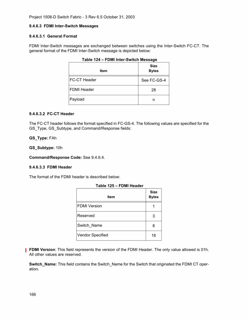
Project 1508-D Switch Fabric - 3 Rev 6.5 October 31, 2003
9.4.6.3 FDMI Inter-Switch Messages
9.4.6.3.1 General Format
FDMI Inter-Switch messages are exchanged between switches using the Inter-Switch FC-CT. Thegeneral format of the FDMI Inter-Switch message is depicted below:
9.4.6.3.2 FC-CT Header
The FC-CT header follows the format specified in FC-GS-4. The following values are specified for theGS_Type, GS_Subtype, and Command/Response fields:
GS_Type: FAh
GS_Subtype: 10h
Command/Response Code: See 9.4.6.4.
9.4.6.3.3 FDMI Header
The format of the FDMI header is described below:
FDMI Version: This field represents the version of the FDMI Header. The only value allowed is 01h.All other values are reserved.
Switch_Name: This field contains the Switch_Name for the Switch that originated the FDMI CT oper-ation.
Table 124 – FDMI Inter-Switch Message
ItemSize
Bytes
FC-CT Header See FC-GS-4
FDMI Header 28
Payload n
Table 125 – FDMI Header
ItemSize
Bytes
FDMI Version 1
Reserved 3
Switch_Name 8
Vendor Specified 16
166

Project 1508-D Switch Fabric - 3 Rev 6.5 October 31, 2003
Vendor Specified Field:
The format of the vendor specified field is depicted in table 126.
Vendor Identifier: Contains the eight byte T10 administered vendor identifier.
Vendor Specified Information: This field contains 8 bytes of vendor specified information. The pro-cessing of the Vendor Specified information shall be subject to the following rules:
a) If the information contained in the Vendor Specified Information field is not recognized or pro-cessed by the server, then the command proceeds as defined;
b) For any FDMI command defined in the standard, the Vendor Specified information shall notcause the server to exhibit any behavior different from that defined for the command.
9.4.6.3.4 Payload
The Payload field is either null or contains the GS Client Payload depending on the FDMI Inter-Switchrequest see table 127. The GS Client payload includes the entire CT Request that was received bythe entry Switch from the HBA, including the CT Header.
9.4.6.4 FDMI Inter-Switch Requests
FDMI Inter-Switch requests are mapped to Request CT_IUs. The following table indicates the opera-tions performed by the HBA Management Server and indicates their associated command codes andpayload contents.
Table 126 – Vendor SpecifiedItem Size (Bytes)
Vendor Identifier 8
Vendor Specified Information 8
Table 127 – FDMI Fabric Internal Command Codes (Part 1 of 2)
Code Mnemonic DescriptionRequest
Attributes Accept Attributes
E100 FDRNDe-Registration Notification
FDMI Header, GS Client Payload
Null
E101 FRNRegistration Notification
FDMI Header, GS Client Payload
Null
E102 FUNUpdate Notification
FDMI Header, GS Client Payload
Null
E103 FDRFDe-Registration Forward
FDMI Header, GS Client Payload
Null
167

Project 1508-D Switch Fabric - 3 Rev 6.5 October 31, 2003
9.4.6.5 FDMI Inter-Switch Responses
9.4.6.5.1 Reject Response
When the destination Switch is unable to perform a requested operation, an HBA Management ServerReject CT_IU is sent to the originating Switch. HBA Management Server Reject CT_IUs specify a rea-son code of x'09' (Unable to perform command request).
9.4.6.5.2 Accept Response
When the destination Switch has successfully performed the requested operation, an HBA Manage-ment Accept CT_IU is sent to the originating Switch indicating completion of the requested operation,and containing any response information associated with the requested operation.
9.4.6.6 FDMI Inter-Switch Operations
9.4.6.6.1 Registration Notification (FRN) Operation
When the HBA Management Server on the entry Switch registers HBA information in its FDMI data-base, the HBA Management Server shall send the FRN request to all switches in the Fabric. The FRNrequest payload shall specify the FDMI header, and the original CT request from the GS client. TheFRN accept payload shall be null.
9.4.6.6.2 De-Register Notification (FDRN) Operation
When the HBA Management Server on the entry Switch de-registers HBA information in its FDMI da-tabase, the HBA Management Server shall send the FDRN request to all switches in the Fabric. The
E104 FUFUpdate Forward
FDMI Header, GS Client Payload
Null
E105 FETCH Fetch FDMI Header HBA/Port List
E106-E10F
Reserved
Table 128 – Reason Code ExplanationEncoded Value
(hex) Description
00 No Additional Explanation
E0 Fetch Unsuccessful
others Reserved
Table 127 – FDMI Fabric Internal Command Codes (Part 2 of 2)
Code Mnemonic DescriptionRequest
Attributes Accept Attributes
168

Project 1508-D Switch Fabric - 3 Rev 6.5 October 31, 2003
FDRN request payload shall specify the FDMI header, and the original CT request from the GS client.The FDRN accept payload shall be null.
9.4.6.6.3 Update Notification (FUN) Operation
When the HBA Management Server on the entry Switch updates HBA information in its FDMI data-base, the HBA Management Server shall send the FUN request to all switches in the Fabric. The FUNrequest payload shall specify the FDMI header, and the original CT request from the GS client. TheFUN accept payload shall be null.
9.4.6.6.4 Update Forward (FUF) Operation
When the HBA Management Server on the entry Switch receives a request to update HBA information,but the Switch is not the Principal HBA Manager for the specified HBA, the HBA Management Servershall send the FUF request to the Switch that is the Principal HBA Manager for the specified HBA. TheFUF request payload shall specify the FDMI header, and the original CT request from the GS client.The FUF accept payload shall be null.
9.4.6.6.5 De-Register Forward (FDRF) Operation
When the HBA Management Server on the entry Switch receives a request to de-register HBA infor-mation, but the Switch is not the Principal HBA Manager for the specified HBA, the HBA ManagementServer shall send the FDRF request to the Switch that is the Principal HBA Manager for the specifiedHBA. The FDRF request payload shall specify the FDMI header, and the original CT request from theGS client. The FDRF accept payload shall be null.
9.4.6.6.6 Fetch
When a Switch becomes part of the Fabric (e.g., result of a Merge), the HBA Management Server shallsend the FETCH request to all Switches in the Fabric to obtain their Registered HBA/Port lists. TheFETCH request payload shall specify the FDMI header. The FETCH accept payload shall return theRegistered HBA/Port list. The format of the Registered HBA/Port list is shown below.
Number of HBA Entries: This field specifies the number of HBA entries contained in the RegisteredHBA/Port list.
Table 129 – Registered HBA/Port ListItem Size (Bytes)
Number of HBA Entries (n) 4
HBA Entry 1 x
HBA Entry 2 y
... ...
HBA Entry n z
169

Project 1508-D Switch Fabric - 3 Rev 6.5 October 31, 2003
HBA Entry: The format of the HBA Entry is depicted in table 130 below.
Number of Port Entries: This field specifies the number of Port entries for the specified HBA.
Port Entry: The format of the Port Entry is depicted in table 131 below.
9.4.6.7 GS Client Initiated FDMI Requests
In addition to the Fabric originated FDMI operations, there are GS client initiated FC-CT commandsthat are forwarded to other switches in the Fabric by the entry Switch. The FC-CT Command Codes
Table 130 – HBA EntryItem Size (Bytes)
HBA Identifier 8
Number of Port Entries (m) 4
Port Entry 1 8
Port Entry 2 8
... ...
Port Entry n 8
Table 131 – Port EntryItem Size (Bytes)
Port_Name 8
170

Project 1508-D Switch Fabric - 3 Rev 6.5 October 31, 2003
defined for use by Fabric Device Management Interface requests of the Distributed HBA ManagementServer are summarized in table 132.
9.4.7 Other Fabric Internal Services
9.4.7.1 Fabric Internal Requests
Fabric internal FC-CT for the distributed Management Server are shown in table 133.
Table 132 – Fabric Device Management Interface CT Commands for the dMSEncoded Value
(hex) Description MnemonicWork
CategoryPayload
Defined in
0100 Get Registered HBA List GRHL Local or 1 to Many
FC-GS-4
0101 Get HBA Attributes GHAT Localor 1-to-1
FC-GS-4
0102 Get Registered Port List GRPL Localor 1-to-1
FC-GS-4
0110 Get Port Attributes GPAT Localor 1-to-1
FC-GS-4
0200 Register HBA RHBA Local FC-GS-4
0201 Register HBA Attributes RHAT Local FC-GS-4
0210 Register Port RPRT Local FC-GS-4
0211 Register Port Attributes RPA Local FC-GS-4
0300 De-Register HBA DHBA Local FC-GS-4
0301 De-Register HBA Attributes DHAT Local FC-GS-4
0310 De-Register Port DPRT Local FC-GS-4
0311 De-Register Port Attributes DPA Local FC-GS-4
Table 133 – Fabric Internal Management Server Operations
Code Mnemonic DescriptionRequest
Attributes Accept Attributes
E020 GCAP Get Management Server Capabilities None Management Server Capabilities
E100-E10F
Reserved for Inter-Switch FDMI Use (See 9.4.6.4)
171

Project 1508-D Switch Fabric - 3 Rev 6.5 October 31, 2003
9.4.7.2 Get Management Server Capabilities (GCAP) Operation
The GCAP operation allows a management server instance on one Switch to query the managementserver capabilities of a management server instance on another Switch in the Fabric.
The responding distributed Management Server shall, when it receives a GCAP operation request, re-turn its capabilities. The GCAP request payload shall be null. The GCAP accept payload contains therequested Management Server Capabilities.
9.4.7.2.1 Capability Entry
The format of the capability entry is shown below. The Management Server Subtype indicates the ser-vice. The Capability mask designates the supported capabilities of the service.
Management Server GS_Subtype: This field shall indicate the Management Server associated withthe capabilities in the entry.
Vendor Specific Capability Bit Mask: This field shall indicate any vendor specific capabilities asso-ciated with the designated Management Server. The format of the field is not defined by this standard.
Subtype Capability Bit Mask: This field shall indicate capabilities associated with the designatedManagement Server.
Table 134 – GCAP Request PayloadItem Size (Bytes)
Null 0
Table 135 – GCAP CT_ACC PayloadItem Size (Bytes)
Number of Capability Entries (n) 4
Capability Entry 1 8
Capability Entry 2 8
... 8
Capability Entry n 8
Table 136 – Capability EntryItem Size (Bytes)
Management Server GS_Subtype 1
Vendor Specific Capability Bit Mask 3
Subtype Capability Bit Mask 4
172

Project 1508-D Switch Fabric - 3 Rev 6.5 October 31, 2003
9.4.7.2.2 Subtype Capability Bit Masks
The Capability Bit Masks currently defined by this standard are listed below.
Table 137 – Fabric Configuration Server (CT_Subtype 01h)Option Bit(s) Description (see 6.1.22.4.3)
0 Basic Configuration Services
1 Platform Configuration Services
2 Topology Discovery Configuration Services
3 Enhanced Configuration Services
4-31 Reserved
Table 138 – Unzoned Name Server (CT_Subtype 02h)Option Bit(s) Description (see 9.4.4)
0 Basic Unzoned Name Services
1-31 Reserved
173

Project 1508-D Switch Fabric - 3 Rev 6.5 October 31, 2003
10 Switch Zone Exchange & Merge
10.1 Overview
This clause describes a mechanism for Switches to exchange zoning data. FC-GS-4 contains a de-scription of the Fabric Zoning Service architecture and management requests for administering zon-ing.
When link parameters have been established for a link and the Switches have a Domain_ID, the twoSwitches joined by this link exchange Zoning Configuration information to make the information con-sistent across the Fabric. The Fabric Management inter-switch messages that are addressed to aFabric Controller are the Merge request and Merge response. These messages are used to resolvethe Zoning Configuration in a Fabric when two Switches are joined. Each Switch determines if theZoning Configuration from the adjacent Switch may be merged with its local Zoning Configuration.The rules for merging Zoning Configurations are described in 10.5.2.
NOTE 37 – This protocol is designed to work when a single inter-switch link is established. Establishing morethan one inter-switch link at the same time may lead to unpredictable effects over the Fabric.
10.2 Joining Switches
Merge request and Merge response messages are used to merge and propagate Zoning Configura-tions when an inter-Switch link becomes available. A merge operation is performed with the adjacentSwitch when an inter-Switch link becomes available, and with all adjacent Switches when changesare made to the local Zoning Configuration as a result of merging the local Zoning Configuration withan adjacent Zoning Configuration.
A Merge request message contains the local Zoning Configuration of the Switch that is generatingthe Merge request, together with a Protocol Version field that defines the format of the Zoning Proto-col used by the Switch, (e.g., Enhanced or Basic).
When a Merge request is received from an adjacent Switch, the receiving Switch determines if the re-quest may be accepted and executed. If the Switch is not busy, but there is a Protocol Version mis-match, or, when the Protocol version matches, the merge is unable to be executed according to therules described in 10.5.2, a Merge response is returned indicating that the Zone Configurations areunable to be merged, and the inter-Switch link is isolated. If the Switch is not busy and the mergemay be executed, a Merge response is returned indicating that the Zone Configurations were suc-cessfully merged. After the successful merge, the Zone Set Name is changed to "Successful ZoneSet Merge: Active Zone Set Name has changed”.
This information exchange may start by sending Merge Request Resource Allocation messages to al-locate the resources needed to process the Merge Request Sequences. An example of the Mergedata flow is provided in 10.5.1.
10.3 Enhanced Zoning Support Determination
When a Switch supporting Enhanced Zoning joins a Fabric, it shall use the ESS SW_ILS(see 6.1.22.4.4) to determine the Enhanced Zoning capabilities of the other Switches. By doing so,the Switch also announces its Enhanced Zoning capabilities to the other Switches of the Fabric.
Each Switch supporting Enhanced Zoning shall maintain the information about the Enhanced Zoningsupport by all Switches in the Fabric. This information is updated whenever a Switch joins or leavesthe Fabric, and it is used to reply to the GFEZ request.
174

Project 1508-D Switch Fabric - 3 Rev 6.5 October 31, 2003
If all the Switches in the Fabric support Enhanced Zoning, then the Enhanced Zoning supported bit(bit 0) of the Fabric Enhanced Zoning support flags of the GFEZ Accept shall be set to one, otherwiseit shall be set to 0.
The value of the Enhanced Zoning enabled bit (bit 1) of the Fabric Enhanced Zoning support flags ofthe GFEZ Accept is instead determined with the Zone Merge protocol because a Switch is able tojoin a Fabric only if it is working in the same mode of the Fabric see 6.1.16).
If all the Switches in the Fabric support the Zone Set Database, then the Zone Set Database support-ed bit (bit 4) of the Fabric Enhanced Zoning support flags of the GFEZ Accept shall be set to one, oth-erwise it shall be set to 0.
10.4 Zoning Framework and Data Structures
10.4.1 Basic Zoning Framework
This clause provides an overview of the Basic Zoning framework associated with the Switch Fabric.The Basic Zoning framework describes zoning entities such as Zoning Objects, Object Members,Member types, and their relationships. The figures below depict the Basic Zoning framework.
175

Project 1508-D Switch Fabric - 3 Rev 6.5 October 31, 2003
Figure 30 – Basic Zoning Framework
Zoning Objects: Three types of Zoning Objects are defined. They are:
a) Zone Set;
b) Zone;
c) Zone Alias.
Zone Set Object: The Zone Set object defines a group of Zones. A Zone Set object contains one ormore members that are Zone objects. In addition, the Zone Set object has two attributes:
Zoning Objects
Zone Set Object - 01h
Zone Object- 02h
Members 1:nZone Object
N_Port_Name - 01h
Zone Alias Object - 03h
Zone Set Object Members 1:n
Zone Object #1
Zone Object #2
Zone Object...
Zone Object #n
Domain & Port - 02h
N_Port_ID - 03h
Alias Name - 04h
Zone Member Types
Zone Member #1
Zone Member #2
Zone Member ...
Zone Member #n
N_Port_Name - 01h
Domain & Port - 02h
N_Port_ID - 03h
Zone Alias Member TypesMembers 1:nZone Alias Object
Zone Alias Member #1
Zone Alias Member #2
Zone Alias Member ..
Zone Alias Member #n
(Reference to Zone AliasObject)
176

Project 1508-D Switch Fabric - 3 Rev 6.5 October 31, 2003
a) Name;
b) Number of Members.
Zone Object: The Zone Object defines a Zone and its members. A Zone object contains one or moreZone Members. Currently defined Zone Member Types are listed below:
a) N_Port_Name;
b) Domain_ID and physical port;
c) N_Port_ID;
d) Zone Alias Name;
The Zone Object has three attributes:
a) Name;
b) Protocol Type;
c) Number of Members.
Zone Alias Object: A Zone Alias object defines a Zone Alias and its members. A Zone Alias objectcontains one or more Zone Alias Members. Currently defined Zone Alias Member Types are listedbelow:
a) N_Port_Name;
b) Domain_ID and physical port;
c) N_Port_ID;
The Zone Alias Name specified as a Zone Member serves as a reference to a Zone Alias object.
The Zone Alias object has two attributes:
a) Name;
b) Number of Members.
177

Project 1508-D Switch Fabric - 3 Rev 6.5 October 31, 2003
Figure 31 – Basic Zoning Hierarchy
Figure 32 – Basic Zoning Object Structure
Zone Set
Zone Zone Zone Zone
ZoneMember
ZoneMember
ZoneMember
ZoneMember
ZoneMember
ZoneAlias
ZoneAlias
Member
ZoneAlias
Member
ZoneAlias
Member
Zone SetAttributes:Zoning Object Type 01hZone Set Name
Number of Zone ObjectsList of Zone Objects
Zone(s)Attributes:Zoning Object Type02hProtocolFlagsZone Name
Number of Zone MembersList of Zone Members
One orMore
Zone MembersAttributes:Zone Member Type 01 - N_Port_Name 02 - Domain_ID and Port 03 - N_Port_ID 04 - Zone Alias Name
LengthZone Member Identifier
One orMore
Zone Alias (s)Attributes:Zoning Object Type03hZone Alias NameNumber of Zone Alias MembersList of Zone Alias Members
Zone Alias MembersAttributes:Zone Alias Member Type 01 - N_Port_Name 02 - Domain_ID and Port 03 - N_Port_ID
LengthZone Alias Member Identifier
One orMore
Flags
Flags
178

Project 1508-D Switch Fabric - 3 Rev 6.5 October 31, 2003
10.4.2 Basic Zoning Data Structures
10.4.2.1 Zoning Object List
The format of the Zoning Object List is depicted in table 139.
Number of Zoning Objects: This field contains a value that specifies the number of Zoning objectscontained in the Zoning Object list.
Zoning Object: This entry contains a Zoning object as described in 10.4.2.2.
10.4.2.2 Zoning Object Format
The general format of a Zoning object is depicted in table 140.
Table 139 – Zoning Object ListItem Size
Number of Zoning Objects 4
Zoning Object 1 x
Zoning Object 2 y
... ...
Zoning Object n z
Table 140 – Zoning ObjectItem Size
Object Type 1
Protocol 1
Reserved 2
Object Name a
Number of Object Members 4
Object Member 1 x
Object Member 2 y
... ...
Object Member n z
179

Project 1508-D Switch Fabric - 3 Rev 6.5 October 31, 2003
Object Type: Valid values for defined Zoning object types are listed in table 141 below.
Protocol: The Protocol attribute shall be reserved for Zone Set and Zone Alias objects. For Zone Ob-jects, if the Protocol field is non-zero, Device_Data and FC-4 Link_Data frames not having the speci-fied protocol value shall not be transmitted between members of the Zone. All other frames shall betransmitted between members of the zone. The values of the Protocol Format are shown intable 142:
Object Name: This attribute specifies the name of the object. The format of this attribute is describedin 10.4.2.3.
Number of Object Members: This field indicates the number of object members.
Object Members: One or more object members are contained in the Zoning object. Object membersmay be other Zoning objects or Zone Members.
10.4.2.3 Name Entry Format
All Name attributes pertaining to Zoning shall use the Name Entry format. Examples include ZoneSet names, Zone names, and Zone Alias names. The Name Entry Format is described in FC-GS-4.
Table 141 – Zoning Object Types
DescriptionValue(hex)
Reserved 00
Zone Set 01
Zone 02
Zone Alias 03
Reserved 04-DF
Vendor Specified E0-FF
Table 142 – Protocol FormatEncoded Value
(hex) Description
00 No Protocol Zoning
01-FF Non-zero values are taken from FC-FS.
180

Project 1508-D Switch Fabric - 3 Rev 6.5 October 31, 2003
10.4.2.4 Zone Member Format
Zone objects shall have Zone Members. The format of a Zone Member is depicted in table 143 be-low.
Zone Member Type: Valid Zone Member types are shown in table 144.
Flags Field: Implementation is vendor specific.
Identifier Length: The identifier length is determined by the Zone Member Type as specified intable 144.
Identifier: The description of the Identifier fields for valid Zone Member Types are depicted intable 144.
Table 143 – Zone Member FormatItem Size
Zone Member Type 1
Reserved 1
Flags 1
Identifier Length 1
Identifier x
Table 144 – Zone Member Type and Identifier Formats
Type (hex) IdentifierSize
(Bytes)
00 Reserved
01 N_Port_Name:
The format of the Zone Member information is aN_Port_Name.
8
02 Domain_ID & Physical Port:
The format of the Zone Member Information is acombination of a Domain_ID + Physical PortIdentifier.
(i.e., 00DDPPPPh; where DD is the Domain_IDand PPPP is the port number).
4
03 N_Port_ID:
24 bit FC address format (00ddaapp). Valid FCaddresses are those assignable to F and FLport attached devices.
4
181

Project 1508-D Switch Fabric - 3 Rev 6.5 October 31, 2003
NOTE 38 – Name field describes either an Alias or Zone name in the format described in FC-GS-4.
04 Alias Name Variable
05-DF Reserved
E0-FF Vendor Specific
Table 144 – Zone Member Type and Identifier Formats
Type (hex) IdentifierSize
(Bytes)
182
Project 1508-D Switch Fabric - 3 Rev 6.5 October 31, 2003
10.4.3 Enhanced Zoning Framework
10.4.3.1 Introduction
In the Enhanced Zoning Framework more Zoning objects are defined to those defined in Basic Zon-ing. This subclause delineates the structures of the Enhanced Active Zone Set and of the EnhancedZone Set Database.
10.4.3.2 Zone Set Database
The Zone Set Database may contain Zoning Object types as defined in the following subclauses. Thecurrently defined Zoning Object types are:
a) Zone Set;
b) Zone;
c) Zone Alias;
d) Zone Attribute.
The Zone Set Database shall not contain the Active Zone Set. The Zone Set Database may containmultiple Zoning objects. Objects defined in the Zone Set Database need not be referenced. In theZone Set Database the Zoning objects may reference each other using names formatted as specifiedin FC-GS-4.
Figure 33 depicts the logical structure of the Zone Set Database.
183

Project 1508-D Switch Fabric - 3 Rev 6.5 October 31, 2003
Figure 33 – Logical Structure of the Zone Set Database
Zone Set 1
Mem A
Zone B Zone C
Zone Set 2
Zone C Zone D
Zone A
Zone A
Mem B Mem C Mem XZone B
Zone C
Zone D
Mem D Mem E Mem Y
Mem A Mem C Mem Y
Mem A Mem B Mem C
Mem D Mem E Mem X
Mem Y
Alias X
Alias Y
Mem F Mem G Mem H
Mem I Mem J Mem K
Zone B
Italics = Reference
Attributes P
Attributes Q
Attributes P
Attributes Q
Attributes P
Attributes Q
Attr a Attr b
Attr a Attr c
184
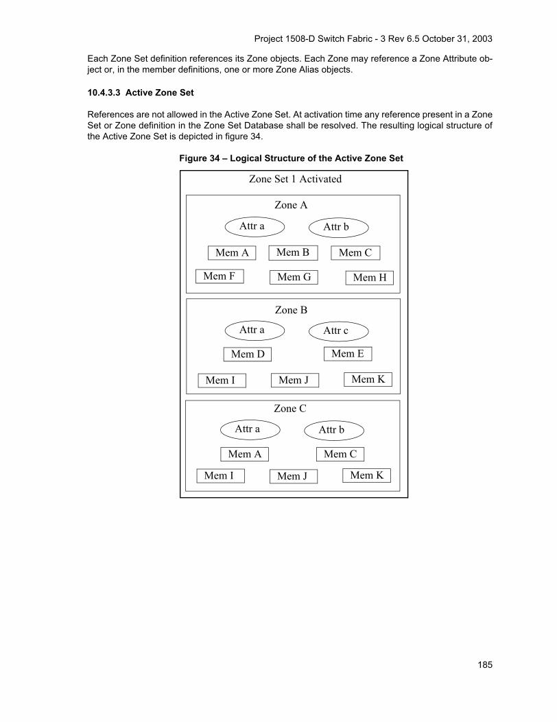
Project 1508-D Switch Fabric - 3 Rev 6.5 October 31, 2003
Each Zone Set definition references its Zone objects. Each Zone may reference a Zone Attribute ob-ject or, in the member definitions, one or more Zone Alias objects.
10.4.3.3 Active Zone Set
References are not allowed in the Active Zone Set. At activation time any reference present in a ZoneSet or Zone definition in the Zone Set Database shall be resolved. The resulting logical structure ofthe Active Zone Set is depicted in figure 34.
Figure 34 – Logical Structure of the Active Zone Set
Zone Set 1 Activated
Zone B
Zone C
Zone A
Mem A Mem C
Mem I Mem J Mem K
Mem A Mem B Mem C
Mem F Mem G Mem H
Mem D Mem E
Mem I Mem J Mem K
Attr a Attr b
Attr a Attr b
Attr a Attr c
185

Project 1508-D Switch Fabric - 3 Rev 6.5 October 31, 2003
10.4.4 Enhanced Zoning Data Structures
10.4.4.1 Zoning Object List
The format of the Zoning Object List is depicted in table 145.
Number of Zoning Objects: This field contains a value that specifies the number of Zoning objectscontained in the Zoning Object list.
Zoning Object: This entry contains a Zoning object. Valid Zoning objects are described in the follow-ing clauses.
10.4.4.2 Zoning Object Types
Currently defined Zoning Object types are listed in table 146 below.
Table 145 – Zoning Object ListItem Size
Number of Zoning Objects 4
Zoning Object 1 x
Zoning Object 2 y
... ...
Zoning Object n z
Table 146 – Zoning Object Types
DescriptionValue(hex)
Reserved 00
Zone Set 01
Zone 02
Zone Alias 03
Zone Reference 04
Zone Attribute Object 05
Reserved 06-DF
Vendor Specified E0-FF
186

Project 1508-D Switch Fabric - 3 Rev 6.5 October 31, 2003
10.4.4.3 Zone Set Object
10.4.4.3.1 Zone Set Object in the Zone Set Database
The Zone Set object used in the zone set database has the attributes described below and the formatdepicted in table 147.
Zone Set Name
The Zone Set Name attribute shall follow the general name format described in FC-GS-4.
Number of Zone References
This attribute shall contain the integer number of zones or zone references in the Zone Set.
Zone Reference
Only Zone Reference objects (Zone Set Member Type 04h) are allowed in the Zone Set Object whenused in the Zone Set Database.
Table 147 – Zone Set Object Format in the Zone Set DatabaseItem Size (bytes)
Zone Set Object Identifier 1
Reserved 3
Zone Set Name a
Number of Zone References 4
Zone Reference #1 x
Zone Reference #2 y
... ...
Zone Reference #n z
187

Project 1508-D Switch Fabric - 3 Rev 6.5 October 31, 2003
10.4.4.3.2 Zone Set Object in the Active Zone Set
The Zone Set object used in the active zone set has the attributes described below and the formatdepicted in table 148.
Number of Zones
This attribute shall contain the integer number of zones in the Zone Set.
Zone
Only Zone objects (Zone Set Member Type 02h) are allowed in the Zone Set Object when used in theActive Zone Set.
10.4.4.4 Zone Reference Object
The Zone Reference object format is depicted in table 149.
Zone Name
The Zone Name attribute shall follow the general name format described in FC-GS-4.
Table 148 – Zone Set Object Format in the Active Zone SetItem Size (bytes)
Zone Set Object Identifier 1
Reserved 3
Number Zones 4
Zone #1 x
Zone #2 y
... ...
Zone #n z
Table 149 – Zone Reference Object FormatItem Size (bytes)
Zone Reference Object Identifier 1
Reserved 3
Zone Name x
188

Project 1508-D Switch Fabric - 3 Rev 6.5 October 31, 2003
10.4.4.5 Zone Object in the Zone Set Database
The Zone object used in the Zone Set Database allows references to other objects. It has the at-tributes described below and the format depicted in table 150.
Zone Name
The format of the Zone Name attribute shall follow the general name format described in FC-GS-4.
Zone Attribute Object Name
The format of the Zone Attribute Object Name attribute shall follow the general name format de-scribed in FC-GS-4. Its value references the Zone Attribute Object whose attributes apply for theZone. A null value (‘00 00 00 00 00 00 00 00’) indicates that no attributes are associated with thatZone definition.
Number of Zone Members
This attribute shall contain the integer number of Zone Members in the Zone.
Zone Member
The zone member format is described in 10.4.4.6.1.
Table 150 – Zone Object Format in the Zone Set Database Item Size (bytes)
Zone Object Identifier 1
Reserved 3
Zone Name a
Zone Attribute Object Name b
Number of Zone Members 4
Zone Member #1 x
Zone Member #2 y
... ...
Zone Member #n z
189
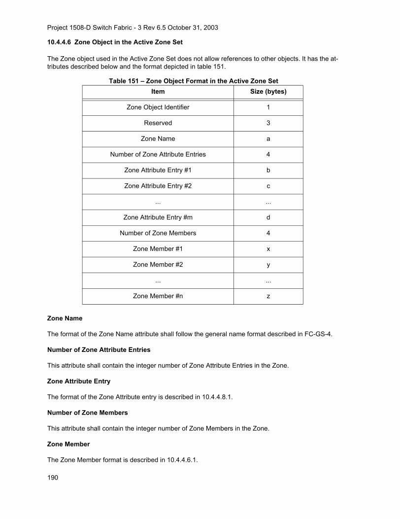
Project 1508-D Switch Fabric - 3 Rev 6.5 October 31, 2003
10.4.4.6 Zone Object in the Active Zone Set
The Zone object used in the Active Zone Set does not allow references to other objects. It has the at-tributes described below and the format depicted in table 151.
Zone Name
The format of the Zone Name attribute shall follow the general name format described in FC-GS-4.
Number of Zone Attribute Entries
This attribute shall contain the integer number of Zone Attribute Entries in the Zone.
Zone Attribute Entry
The format of the Zone Attribute entry is described in 10.4.4.8.1.
Number of Zone Members
This attribute shall contain the integer number of Zone Members in the Zone.
Zone Member
The Zone Member format is described in 10.4.4.6.1.
Table 151 – Zone Object Format in the Active Zone Set Item Size (bytes)
Zone Object Identifier 1
Reserved 3
Zone Name a
Number of Zone Attribute Entries 4
Zone Attribute Entry #1 b
Zone Attribute Entry #2 c
... ...
Zone Attribute Entry #m d
Number of Zone Members 4
Zone Member #1 x
Zone Member #2 y
... ...
Zone Member #n z
190

Project 1508-D Switch Fabric - 3 Rev 6.5 October 31, 2003
10.4.4.6.1 Zone Member Format
Zone Objects shall have Zone Members. The format of a Zone Member is depicted in table 152 be-low.
Zone Member Type
Valid Zone Member types are shown in table 153.
Identifier Length
The identifier length is determined by the Zone Member Type as specified in table 153.
Identifier
The description of the Identifier fields for valid Zone Member Types are depicted in table 153.
Table 152 – Zone Member FormatItem Size
Zone Member Type 1
Reserved 2
Identifier Length 1
Identifier x
Table 153 – Zone Member Type and Identifier Formats (Part 1 of 2)
Type (hex) IdentifierSize
(Bytes)
00 Reserved
01 N_Port_Name:
The format of the Zone Member information is aN_Port_Name.
8
02 Domain_ID & Physical Port:
The format of the Zone Member Information is acombination of a Domain_ID + Physical PortIdentifier.
(i.e., 00DDPPPPh; where DD is the Domain_IDand PPPP is the port number).
4
191

Project 1508-D Switch Fabric - 3 Rev 6.5 October 31, 2003
Vendor Specified Zone Member Format
The Vendor Specified Zone Member Identifier format is depicted in table 154.
Vendor Identifier: Contains the eight byte T10 administered Vendor Id.
Vendor Specified Value: This field contains the Vendor Specified Value.
Pad: Fill bytes are added as necessary to the end of the Vendor Specified Value in order to ensurethat the total length of the Vendor Specified Zone Member is a multiple of four. Fill bytes shall be nulls(00h). The number of fill bytes (m) is zero, one, two, or three depending on the length of the actualvalue (n).
03 N_Port_ID:
24 bit FC address format (00ddaapp). Valid FCaddresses are those assignable to F and FLport attached devices.
4
04 Alias Name:
The format of the Zone Member information is a General Name.
a
05 Node_Name:
The format of the Zone Member information is aNode_Name.
8
06 F_Port_Name:
The format of the Zone Member information is aF_Port_Name.
8
07-DF Reserved
E0-FF Vendor specified
Table 154 – Zone Member Identifier Format - Vendor SpecifiedItem Size (Bytes)
Vendor Identifier 8
Vendor Specified Value n
Pad m
Table 153 – Zone Member Type and Identifier Formats (Part 2 of 2)
Type (hex) IdentifierSize
(Bytes)
192

Project 1508-D Switch Fabric - 3 Rev 6.5 October 31, 2003
10.4.4.7 Zone Alias Object
The Zone Alias object has the attributes described below and the format depicted in table 155.
Zone Alias Name
The format of the Zone Alias Name attribute shall follow the general name format described in FC-GS-4.
Number of Zone Alias Members
This attribute shall contain the integer number of Zone Alias Members in the Zone Alias.
Zone Alias Member
The Zone Alias Member has the format described in 10.4.4.6.1. All Zone Member Identifier Typesmay be used, with the exception of the Alias Name member (type ‘04’).
Table 155 – Zone Alias Object FormatItem Size (bytes)
Zone Alias Object Identifier 1
Reserved 3
Zone Alias Name a
Number of Zone Alias Members 4
Zone Alias Member #1 x
Zone Alias Member #2 y
... ...
Zone Alias Member #n z
193

Project 1508-D Switch Fabric - 3 Rev 6.5 October 31, 2003
10.4.4.8 Zone Attribute Object
The Zone Attribute object is a variable length structure that contains extensible attributes that may beassociated with a Zone. The format of the Zone Attribute object is depicted in table 156 andtable 157.
Zone Attribute Object Name
The format of the Zone Attribute Object Name attribute shall follow the general name format de-scribed in FC-GS-4.
Number of Zone Attribute Entries
This field specifies the number of Zone Attribute Entries contained in the Zone Attribute Block. A val-ue of zero in this field shall indicate that no attributes are registered.
Table 156 – Zone Attribute Object Format Item Size (bytes)
Zone Attribute Object Identifier 1
Reserved 3
Zone Attribute Object Name x
Zone Attribute Block w
Table 157 – Zone Attribute Block FormatItem Size (Bytes)
Number of Zone Attribute Entries 4
Zone Attribute Entry #1 x
Zone Attribute Entry #2 y
... ...
Zone Attribute Entry #n z
194

Project 1508-D Switch Fabric - 3 Rev 6.5 October 31, 2003
10.4.4.8.1 Zone Attribute Entry Format
The format of the Zone Attribute Entry is depicted in table 158.
Zone Attribute Type: This field indicates the attribute entry type. Valid Zone Attribute Types are de-picted in table 159 and shall be restricted to a value between 0000h and 00FFh
Zone Attribute Length: This field indicates the total length in bytes of the Zone Attribute Entry. Thislength shall be a multiple of four and includes the following fields
a) Zone Attribute Type;
b) Zone Attribute Length;
c) Zone Attribute Value.
Zone Attribute Value: This field specifies the actual attribute value. If present, Attribute Values shallbe at least four bytes in length and the length shall be a multiple of four. For Attribute Value fields, fillbytes are added as necessary to the end of the actual value in order to ensure that the length of thevalue field is a multiple of four. Fill bytes shall be nulls (00h). The number of fill bytes (m) is zero, one,two, or three depending on the length of the actual value (n). Therefore the total length of the valuefield is (n+m).
10.4.4.8.1.1 Protocol Attribute
When a Protocol Attribute Type is specified, the Protocol Attribute Value specifies the FC-4 type forwhich protocol zoning is enforced. Valid values are 01h-FFh. If the FC-4 Type is non-zero,Device_Data and FC-4 Link_Data frames not having the specified FC-4 Type value shall not be
Table 158 – Zone Attribute Entry FormatItem Size (Bytes)
Zone Attribute Type 2
Zone Attribute Length 2
Zone Attribute Value x
Table 159 – Zone Attribute TypesZone Attribute Type
(hex) Description
0001 Protocol
0002 Broadcast Zone
0003 Hard Zone
00E0 Vendor Specified
other values Reserved
195

Project 1508-D Switch Fabric - 3 Rev 6.5 October 31, 2003
transmitted between members of the Zone. All other frames shall be transmitted between membersof the zone. The format of the Protocol Attribute Value is depicted in table 160.
10.4.4.8.1.2 Broadcast Zone Attribute
Broadcast zoning is enabled by setting the Broadcast Zone attribute on zones that contain ports thatsend or receive broadcast frames. Use of the Broadcast Zone attribute allows multi-protocol devicesto send broadcast frames to some devices but not to others. The Broadcast Zone attribute only affectsthe processing of broadcast frames. The Broadcast Zone attribute has no effect on zoning enforce-ment for Name Server, RSCN, or hard zoning.
When zoning is active, broadcast frames are delivered to all logged in Nx_Ports that share a broadcastzone with the source of the frame (as indicated by the S_ID of the frame). This implies that if zoningis active and no zones have the Broadcast Zone attribute set, then no broadcast frames are delivered.Zoning is enforced at the destination Switch. Broadcast zoning shall not have any affect on the Switchto Switch routing of frames.
If any NL-Port attached to an FL-Port shares a broadcast zone with the source of the broadcast frame,or zoning is not active, the frame shall be sent to the all the devices on the loop using the OPNfr openreplicate primitive. Use of the OPNyr selective replicate is prohibited (see FC-DA).
Broadcast zoning shall be enforced on the destination switches, using the S_ID of the broadcast frameto determine the zones. Some zone member types are unable to be directly mapped to a Fibre Chan-nel address. For these types a Switch shall use the Name Server to get the FC address associatedwith the zone member data. Similar discovery may be needed to implement hard zones.
a) N_Port_Name or Node_Name zone member: Use the GID_PN or GID_NN Name Server com-mands to get the FC address. Note that GID_NN may return multiple FC addresses.
b) Domain + Port zone member: There is no current Name Server command to get the FC ad-dress associated with the Domain plus port number.
c) Fabric Port_Name zone member: Use the GID_FPN name server command.
If address discovery finds FC addresses for non FC address zone members, ports in those broadcastzones become accessible to the ports whose FC addresses have been discovered. If ports becomeaccessible to new broadcast sources, an RSCN shall be issued for those ports. If a Switch is issuingan RSCN for some other reason after address discovery, and the RSCN includes newly accessibleports, a separate RSCN for address discovery for those ports is not necessary.
If zoning is inactive in the Fabric, then broadcast frames are delivered to all logged in Nx_Ports.
There is no value associated with the Broadcast Zone Attribute. Therefore the Zone Attribute Lengthshall be set to four.
Table 160 – Protocol Attribute ValueItem Size (Bytes)
FC-4 Type 1
Reserved 3
196

Project 1508-D Switch Fabric - 3 Rev 6.5 October 31, 2003
10.4.4.8.1.3 Hard Zone Attribute
Hard zoning is specified by setting the Hard Zone attribute.
When the Hard Zone attribute is specified, the zone configuration shall use hard zoning enforcementsee 3.1.48). If an implementation is unable to enforce the zone configuration using hard zoningenforcement (e.g., enforcing the zone configuration requires hardware resources that are notavailable), the activation of the zone configuration shall fail.
When the Hard Zone attribute is not specified, the zoning configuration shall be enforced in one ofthe following ways:
a) hard zoning enforcement; or
b) soft zoning enforcement (see 3.1.77).
The zone configuration should be enforced using hard zoning enforcement whenever possible.
If zoning for an Nx_Port is enforced using hard zoning enforcement for any zone, zoning for thatNx_Port shall be enforced using hard zoning enforcement for all zones in which it is a member.
The activation of a hard zone may succeed because some of the Nx_Ports specified in the zoningconfiguration are not connected to the Fabric at activation time. If a FLOGI request received fromsuch an Nx_Port makes it impossible to enforce the zoning configuration using hard zoningenforcement, then the Fabric shall reject or discard, as appropriate for the class of service, anyframes not addressed to Fabric Services to or from that Nx_Port.
Fabrics may be composed of Switches that support hard zoning and Switches that support only softzoning. The Fabric administrator decides which Nx_Ports are to be managed with hard zoning, andwhich ones with soft zoning.
The Fabric administrator may manage the situation where some Nx_Port need to be restricted withhard zoning and others with soft zoning by defining two overlapping zones, one with the Hard Zoningattribute and the other without the Hard Zoning attribute. The zone without the Hard Zoning attributedefines which Nx_Ports are allowed to communicate. The zone with the Hard Zoning attribute definesthe subset of these Nx_Ports for which Zoning shall be enforced on a frame-by-frame basis.
There is no value associated with the Hard Zone Attribute. Therefore the Zone Attribute Length shallbe set to four.
Hard zoning enforcement requires a mapping of zone members to N_Port_IDs. A Switch may use thefollowing name server requests to perform this mapping:
a) N_Port_Name member type. Use the GID_PN Name Server command;
b) Node_Name member type. Use the GID_NN Name Server command (which may return multi-ple N_Port_IDs);
c) F_Port_Name member type. Use the GID_FPN Name Server command.
197

Project 1508-D Switch Fabric - 3 Rev 6.5 October 31, 2003
10.4.4.8.1.4 Vendor Specified Zone Attribute
The format of the The Vendor Specified Attribute Value is depicted in table 161.
Vendor Identifier: Contains the eight byte T10 administered Vendor Id.
Vendor Specified Value: This field contains the Vendor Specified Value.
Pad: Fill bytes are added as necessary to the end of the Vendor Specified Value in order to ensurethat the total length of the Vendor Specified Zone Member is a multiple of four. Fill bytes shall be nulls(00h). The number of fill bytes (m) is zero, one, two, or three depending on the length of the actualvalue (n).
Table 161 – Vendor Specified Attribute ValueItem Size (Bytes)
Vendor Identifier 8
Vendor Specified Value n
Pad m
198
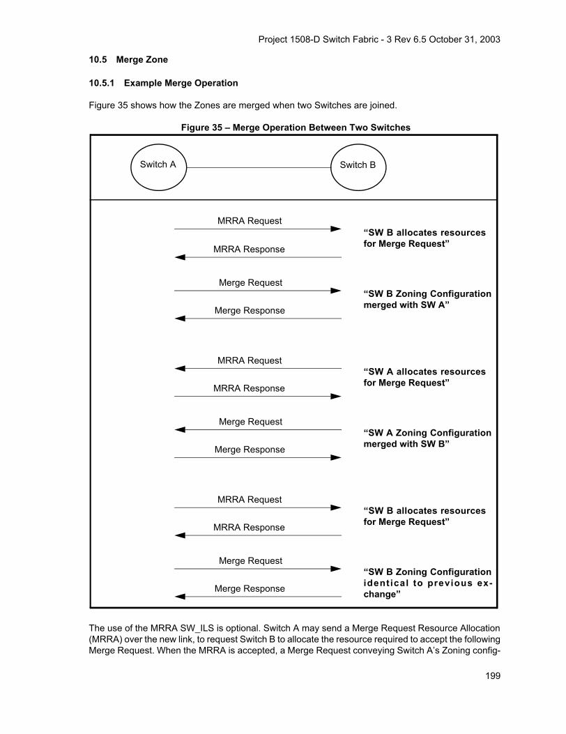
Project 1508-D Switch Fabric - 3 Rev 6.5 October 31, 2003
10.5 Merge Zone
10.5.1 Example Merge Operation
Figure 35 shows how the Zones are merged when two Switches are joined.
Figure 35 – Merge Operation Between Two Switches
The use of the MRRA SW_ILS is optional. Switch A may send a Merge Request Resource Allocation(MRRA) over the new link, to request Switch B to allocate the resource required to accept the followingMerge Request. When the MRRA is accepted, a Merge Request conveying Switch A’s Zoning config-
Switch A
“SW B Zoning Configurationmerged with SW A”
MRRA Request
MRRA Response
“SW B allocates resourcesfor Merge Request”
Merge Request
Merge Response
Switch B
“SW A Zoning Configurationmerged with SW B”
MRRA Request
MRRA Response
“SW A allocates resourcesfor Merge Request”
Merge Request
Merge Response
“SW B Zoning Configurationidentical to previous ex-change”
MRRA Request
MRRA Response
“SW B allocates resourcesfor Merge Request”
Merge Request
Merge Response
199

Project 1508-D Switch Fabric - 3 Rev 6.5 October 31, 2003
uration is sent to Switch B. Switch B merges the two Zoning configurations and changes the name ofthe Active Zone Set to " Successful Zone Set Merge: Active Zone Set Name has changed". SinceSwitch B’s Zoning configuration has changed, it transmits its new Zoning configuration on all ISLs, in-cluding the ISL connecting with Switch A. Switch A receives Switch B’s new Zoning configuration, thatit merges with its Zoning configuration and changes the Zone Set Name to "The Active Zone Set haschanged due to a Zone Merge". After the merge, Switch A sends out its new Zoning configuration onall ISLs. When Switch B receives the new Zoning configuration, it confirms that it has an identical Zon-ing configuration and sends a Merge Response to end the Zone Merge.
Figure 36 shows the Zone Merge process when more than two Switches are involved. Note that initialstate is Switches connected but no merge processing has begun.
200

Project 1508-D Switch Fabric - 3 Rev 6.5 October 31, 2003
Figure 36 – Merge Operation Among Several Switches
10.5.2 Merge Zone Rules
10.5.2.1 Merge Rules in Basic Zoning
In Basic Zoning, when adjacent Switches exchange zoning information, they shall abide by the rulesin table 162.
Switch A Switch B Switch C
“SW B Zoning Configurationmerged with SW A”
“SW A Zoning Configurationmerged with SW B”
“SW B Zoning Configurationidentical to previous exchange”
“SW C Zoning Configurationmerged with SW B”
“SW B Zoning Configurationmerged with SW C”
“SW C Zoning Configurationidentical to previous exchange”
“SW A Zoning Configurationmerged with SW B”
“SW B Zoning Configurationidentical to previous exchange”
201

Project 1508-D Switch Fabric - 3 Rev 6.5 October 31, 2003
Table 162 – Basic Zoning Merge Rules
NOTE 39 – To prevent potential ISL isolation, it is suggested that zoning be inactivated and a zone set propa-gated through the Fabric by the techniques documented in clause 10.6.
If a received Zoning Configuration contains some unsupported member types, the Zone Merge shallfail.
10.5.2.2 Merge Rules in Enhanced Zoning
In Enhanced Zoning the Merge behavior depends by the Merge Control setting. Merge Control is aFabric wide setting that indicates the type of behavior two switches exhibit as a result of a merge op-eration. This setting may be set as Allow or Restrict. A setting of Allow means that the two databasesare merged according to the specified merge rules, and the resulting database is the union of the twodatabases. A setting of Restrict indicates that if the two databases on the corresponding switches arenot identical, then the links between the two switches shall become isolated.
Before the merge rules pertaining to the Zoning Database are applied, the Zone Merge flags shall becompared.
If one of the two Switches does not support the Zone Set Database and the other one is using it (asindicated by the Zone Merge flags) then no merge shall occur and the ISL shall become isolated.
If the Merge Control or Default Zone settings are not equal for both Switches, then no merge shall oc-cur and the ISL shall become isolated. If the Merge Control and Default Zone settings are equal, ad-jacent Switches exchanging zoning information shall abide by the rules in table 163. If the localZoning Database is modified as a result of the merge, the new database is propagated to the neigh-boring Switches.
If a received Zoning Configuration contains some unsupported member types, the Zone Merge shallfail.
Adjacent Zoning Configuration Local Zoning Configuration Result in Local Switch
Zone Set State is Deactivated.
Zone Set State isActivated or Deactivated.
No change
Zone Set State is Activated.
Zone Set State is Deactivated. Zone Set gets the Adjacent Zone Set State (i.e., the Zone Set is activated).
Zone Set gets the adjacent Zone Set.
Adjacent Zone Set is equal to the Local Zone Set No change.
Adjacent and Local Zone Sets contain a Zone with the same name but different members, or different
Protocol Types
ISL Isolated.
Adjacent Zone Set contains Zones that are not included in the Local Zone Set, and/or Local Zone Set contains Zones that are not included in the Adjacent
Zone Set.
Zone Set State becomes Activated.Zone Set is the merge of the local Zones plus the
Adjacent Zones. The Zone Set Name is changed to " Successful Zone Set Merge: Active Zone Set
Name has changed ".
202

Project 1508-D Switch Fabric - 3 Rev 6.5 October 31, 2003
Table 163 – Enhanced Zoning Merge Rules
10.6 Fabric Management Session Protocol
10.6.1 Fabric Management Session Protocol Overview
Requests to change a Fabric's Zoning Configuration or security policies are a result of an administra-tion action or control requests via the Management Server. To keep consistency in the Fabric, theFabric Management Session protocol ensures that only one management entity may change theFabric at one time. Requests may be made to activate or deactivate a Zone Set, or security policy.The Switch that receives a change request is referred to as the Managing Switch. The ManagingSwitch validates the request and exchanges inter-Switch messages with the other Switches in theFabric. The protocol for locking the Fabric during policy changes is the Fabric Management SessionProtocol.
The policy change requests serviced by the Managing Switch are used to:
a) reserve Change Authorization in each Switch in the Fabric (blocking any other changes fromtaking place while this change is in progress);
Condition Before Merge Result in Local Switch
Adjacent Zoning Database is equal to the Local Zoningdatabase. Merge Control = Restrict or Allow
No change.
The local and adjacent Zoning Databases contain azone set, zone, or zone alias object with the same name but
unlike members, Merge Control = Restrict or Allow
ISL Isolated.
The local and adjacent Zoning Databases containreferences with the same name but with different definitions,
Merge Control = Restrict or Allow
ISL Isolated
The local and adjacent Zoning Databases containzones with the same name but with different attributes,
Merge Control = Restrict or Allow
ISL Isolated
Adjacent Zoning Database contains zones or aliasesthat are not included in the local Zoning Database.
Merge Control = Allow.
Zoning Database is the union of the local database plus the
adjacent database
Local Zoning Database is empty, Adjacent Fabric Zonedatabase contains data. Merge Control = Allow.
Data from Adjacent database is used to populate Local database
Adjacent Zoning Database contains zones or aliasesthat are not included in the local Zoning Database.
Merge Control = Restrict.
ISL Isolated
Local Zoning Database is empty, Adjacent Fabric Zonedatabase contains data. Merge Control = Restrict.
ISL Isolated
Adjacent Zoning Database is empty, Local Fabric Zone database contains data. Merge Control = Restrict.
ISL Isolated
Adjacent Zoning Database is empty, Local Fabric Zone database contains data. Merge Control = Allow.
No Change
203

Project 1508-D Switch Fabric - 3 Rev 6.5 October 31, 2003
b) stage configuration changes in each Switch in the Fabric;
c) apply the staged configuration change in each Switch in the Fabric, and;
d) release Change Authorization in each Switch in the Fabric.
Acquire Change Authorization request and response messages are used to reserve Local ChangeAuthorization in each Switch in the Fabric (i.e., to establish Fabric Management Sessions betweenthe Managing Switch and the Managed Switches in the Fabric). Stage Fabric Configuration Updaterequest and response messages are used to distribute a Configuration update to each Switch in theFabric in order to verify that each Switch is able to implement the change. Update Fabric Configura-tion request and response messages are used to modify the Configuration on each Switch in theFabric. Release Change Authorization request and response messages are used to release LocalChange Authorization in each Switch in the Fabric (i.e., end the Fabric Management Sessions).
10.6.2 Reserving Fabric Change Authorization
The Managing Switch shall send an Acquire Change Authorization request to each Managed Switchin the Fabric to reserve the Fabric Change Authorization. Each Acquire Change Authorization re-quest message includes a list of the Domain_IDs of the Managed Switches being included in the up-date.
Each Managed Switch that receives an Acquire Change Authorization request shall return an AcquireChange Authorization response to the Managing Switch. The Acquire Change Authorization re-sponse message is either an SW_ACC that indicates success, or an SW_RJT that specifies why theAcquire Change Authorization operation was unsuccessful. The Managed Switch returns anSW_RJT indicating “Fabric Changing” if the Domain_IDs the Managed Switch knows to be in theFabric are not the same as the Domain_IDs identified in the request by the Managing Switch. TheManaged Switch returns an SW_RJT indicating “Busy” if its Local Change Authorization is already re-served by another process. Otherwise, the Managed Switch reserves Local Change Authorization forthe Managing Switch, and returns an SW_ACC indicating the operation was “Successful”.
The Managing Switch shall wait until an Acquire Change Authorization response has been receivedfrom each Managed Switch in the Fabric. If any of the responses indicate that a Managed Switch isBusy or that the Fabric is Changing, the Managing Switch shall initiate the process to release FabricChange Authorization (see 10.6.5). If all the responses indicate that Local Change Authorization wassuccessfully acquired, the Managing Switch shall initiate the process to stage the update(see 10.6.3).
10.6.3 Staging the Fabric Configuration
The Managing Switch shall send a Stage Fabric Configuration Update request to each ManagedSwitch in the Fabric to stage the Fabic Configuration. The Stage Fabric Configuration Update requestincludes a change command and the appropriate operation data.
Each Managed Switch that receives a Stage Fabric Configuration Update request shall return aStage Fabric Configuration Update response to the Managing Switch. The Stage Fabric Configura-tion Update response message is either an SW_ACC that indicates success, or an SW_RJT thatspecifies why the Stage Fabric Configuration operation was unsuccessful.
If a received Zoning Configuration contains some unsupported member types, the Stage Fabric Con-figuration shall fail.
204

Project 1508-D Switch Fabric - 3 Rev 6.5 October 31, 2003
The Managing Switch shall wait until a Stage Fabric Configuration Update response has been re-ceived from each Managed Switch in the Fabric. If a staging error occurred, the process to releaseFabric Change Authorization (see 10.6.5) shall be initiated. If the update was successfully staged inall the Switches in the Fabric, the process to update the Fabric Configuration (see 10.6.4) shall be ini-tiated.
10.6.4 Updating the Fabric Configuration
The Managing Switch shall send an Update Fabric Configuration request to each Managed Switch inthe Fabric to update the Fabric Configuration. There is no data included in the Update Fabric Config-uration request message.
Each Managed Switch that receives an Update Fabric Configuration request shall return an UpdateFabric Configuration response to the Managing Switch. The Update Fabric Configuration responsemessage is either an SW_ACC that indicates success, or an SW_RJT that specifies why the UpdateFabric Configuration operation was unsuccessful.
The Managing Switch shall wait until an Update Fabric Configuration response has been receivedfrom each Managed Switch in the Fabric. The Managing Switch shall then initiate the process to re-lease Fabric Change Authorization (see 10.6.5).
10.6.5 Releasing Fabric Change Authorization
The Managing Switch shall send a Release Change Authorization request to each Managed Switchin the Fabric that has reserved Local Change Authorization for the Managing Switch. There is no dataincluded in the Release Change Authorization request message.
Each Managed Switch that receives a Release Change Authorization request shall return a ReleaseChange Authorization response to the Managing Switch. The Release Change Authorization re-sponse message is either an SW_ACC that indicates success, or an SW_RJT that specifies why theRelease Change Authorization operation was unsuccessful.
The Managing Switch shall wait until a Release Change Authorization response has been receivedfrom each Managed Switch in the Fabric at which time the Fabric update is complete.
10.6.6 Mapping of a GS Session to a Fabric Session
In the context of Enhanced Zoning Management, a management action (i.e., write access to the Zon-ing Database) to the Zone Server shall occur only inside a GS session. A GS session is delimited bythe CT requests Server Session Begin (SSB) and Server Session End (SSE), directed to the Man-agement Service and with GS_Subtype specifying the Zone Server. Query requests that result inread access to the Zoning Database are not required to be issued inside a GS session, although theinformation which they report is only consistent inside a GS session.
The GS session on the Zone Server side is translated in a lock of the Fabric on the Fabric side, usingthe Fabric Management Session Protocol. This ensures serialized management access to the ZoningDatabase by different management applications, and to guarantee a deterministic behavior.
The Switch handling the Zone Server CT requests, on receiving the SSB CT request shall try to be-come also the Managing Switch of the Fabric Management Session Protocol. As such it shall sendthe ACA SW_ILS to all the other Switches in the Fabric. The result of this action may be one of thefollowing:
205

Project 1508-D Switch Fabric - 3 Rev 6.5 October 31, 2003
a) Each other Switch responds to the ACA with an SW_RJT indicating failure. This means that theFabric is already locked by another Switch, and so somebody else is managing the Zoning Da-tabase. The Zone Server shall reject the SSB CT request. The managing application may retrylater.
b) Some Switches respond to the ACA with an SW_ACC indicating success, some with anSW_RJT indicating failure. This means that another Switch is trying to lock the Fabric at thesame moment. The Switch shall send an RCA SW_ILS to each Switch that accepted the ACAto release its attempt to lock the Fabric. The Zone Server shall reject the SSB CT request. Themanaging application may retry later.
c) Each other Switch responds to the ACA with an SW_ACC indicating success. This means thatthe Switch has been successful in locking the Fabric, and it owns the lock. The Switch shallprepare a copy of the Zoning Database for the subsequent management actions, and after thatthe Zone Server shall accept the SSB CT request.
At this point the management application may manage the Zoning Database using the EnhancedZoning Commands. The Zone Server shall handle the requests applying them to the copy of the Zon-ing Database. The Zoning Database present in all the other Switches of the Fabric shall not be affect-ed by these Enhanced Zoning Commands.
To apply the updated Zoning Database to the Fabric, the Management Application shall send a Com-mit (CMIT) CT request to the Zone Server. The Zone Server shall perform a consistency check of theupdated Zoning Database. If the consistency check fails, then the Zone Server shall reject the CMITCT request, with an appropriate reason code. Consistency checks may fail for many reasons includ-ing the following:
a) A Zone Set Object in the Zone Set Database references Zone Objects that do not exist;
b) A Zone Object in the Zone Set Database references Zone Alias Objects that do not exist;
c) A Zone Object in the Zone Set Database references Zone Attribute Objects that do not exist.
If the consistency check succeeds, then the Managing Switch shall stage the new Zoning Databaseto the other Switches of the Fabric, sending to each Switch the SFC SW_ILS.
a) If one or more Switches reject the SFC SW_ILS, then this may mean that these Switches arenot able to support and enforce the new Zoning Database. The Fabric is unable to have a con-sistent Zoning Database, and so the Zone Server shall reject the CMIT CT request.
b) If all the Switches accept the SFC SW_ILS, then the Fabric is able to have a consistent ZoningDatabase. For certain operations the Managing Switch may need to send a second SFC mes-sage to each managed Switch (see 10.6.7). When all switches have accepted the SFCs theyare prepared to successfully update the zoning definitions. Then the Managing Switch shallsend to each other Switch the UFC SW_ILS to make the staged Zoning Database the FabricZoning Database.
To terminate the GS session, the Management Application shall send a Server Session End (SSE)CT request to the Zone Server. Then the managing Switch shall end the Fabric Management Ses-sion by sending an RCA SW_ILS to every Switch in the Fabric. When every RCA has been accepted,the managing Switch shall destroy the copy of the Zoning Database and the Zone Server shall acceptthe SSE CT request.
206

Project 1508-D Switch Fabric - 3 Rev 6.5 October 31, 2003
If a management application does not send a CMIT request inside a GS session, then every modifi-cation that it may have performed is not applied to the Fabric and is lost. The management Applica-tion may issue the CMIT request more than one time inside the same GS session.
If after a successful SSB CT request a SSE CT request is never received (i.e, the management appli-cation locks the Fabric and then crashes), the Fabric Zone Server shall close the GS session if itdoes not receive any Enhanced Zoning Commands for 2 minutes with a 10% tolerance. Consequent-ly, the Managing Switch shall release the lock over the Fabric. Management applications are expect-ed to keep the session alive even in absence of management inputs.
If instead the Managing Switch crashes while locking the Fabric, the other Switches may detect thesituation and release the lock.
10.6.7 Fabric Behavior to Handle the CT SFEZ Request
If the Fabric is functioning in Basic mode, and the SFEZ command has requested that the Zoning op-erational mode of the Fabric be changed to Enhanced, the Switch handling the CT SFEZ requestshall initiate a Fabric Management Session. This causes a redistribution of the existing Zoning Data-base to the other Switches of the Fabric by using the operation request value ‘Activate Zone Set En-hanced’ in a Stage Fabric Configuration (SFC) SW_ILS. In this manner the Zoning Database isdistributed using the Enhanced Zoning Data structures described in 10.4.4. If this step is successful,then the Zoning Policy Flags requested by the SFEZ command are propagated to the other Switchesof the Fabric by using the operation request value ‘Set Zoning Policies’ in a second Stage FabricConfiguration (SFC) SW_ILS. If this step is successful, the UFC SW_ILS is used to apply the newconfiguration, changing the Zoning operational mode of all Switches in the Fabric to Enhanced mode.The Fabric Management Session shall then be released.
If the Fabric is functioning in Enhanced mode, then only the SFEZ command changes the Fabric’sZoning Policies. This causes a Fabric Management Session to be initiated and an SFC SW_ILS to besent to all Switches. The operation request value ‘Set Zoning Policies’ shall be used in this SFCSW_ILS. If a Fabric Session is already active, then the SFEZ command shall generate an immediateSFC SW_ILS with operation request value ‘Set Zoning Policies’ and an UFC SW_ILSs, keeping alivethe existing session.
NOTE 40 – Zoning structures managed within the Enhanced Zoning Framework may not be subsequentlymanaged using management operations defined in the Basic Zoning Framework. In addition, no mechanismexists to convert from Enhanced Zoning mode to Basic Zoning mode.
207

Project 1508-D Switch Fabric - 3 Rev 6.5 October 31, 2003
11 Distributed broadcast
11.1 Overview
Distributed broadcast provides a mechanism to distribute Broadcast frames without duplicating themor forming a loop. It is based on the FSPF tree with additional rules to provide one and only one broad-cast path. The key is to build the same spanning tree with the same root for all switches.
Broadcast frames shall be Class 3 frames with a D_ID of FFFFFFh specified.
11.2 Spanning tree
The following list of rules are used to determine which ISLs are broadcast ISLs, and which are not:
1) Lowest Domain_ID Switch becomes the root of the tree;
2) Build the Shortest Path tree using FSPF cost as metric;
3) If a link is advertised with different costs in the two directions, the cost advertised by the Switchnearer to the root Switch (i.e., the upstream Switch) shall be used to determine the lowest costpath;
NOTE 41 – This is necessary when the two switches advertise different costs for ISLs;
4) If a Switch has multiple equivalent paths to the root of the tree, the ISL to the upstream Switchwith the lowest Domain_ID shall be selected;
5) If there are multiple equivalent ISLs between a pair of switches, the ISL connected to the up-stream Switches’ lowest E_Port Index shall be selected;
6) The E_Ports selected in this process (broadcast member E_Ports) are used to forward broad-cast frames;
The following set of rules are used for forwarding broadcast frames through the Fabric once the broad-cast member E_Ports are identified:
a) A broadcast frame received on any Fx_Port is forwarded on all broadcast member E_Ports. Inaddition if zoning is enabled the broadcast frame is forwarded to all other Fx_ports in thebroadcast zone on that Switch, or if zoning is not enabled on all other Fx_ports on that Switch;
b) A broadcast frame received on any broadcast member E_Port is forwarded on all other broad-cast member E_Ports on that Switch. In addition if zoning is enabled the broadcast frame is for-warded to all other Fx_ports in the broadcast zone on that Switch, or if zoning is not enabled onall other Fx_ports on that Switch;
c) A broadcast frame received on any other port is discarded.
11.2.1 Spanning tree example
In the example in figure 37, the Switch with Domain_ID 5 is the root of the broadcast tree. FromDomain_ID 7 to Domain_ID 5, there are 2 equal cost ISLs, so the path from Domain_ID 7 port 5 toDomain_ID 5 port 1 becomes the broadcast ISL. From Domain_ID 30 to the root, there are multipleequal cost paths. Domain_ID 7 is the lowest upstream Switch, therefore, this path is chosen. Secondly,
208

Project 1508-D Switch Fabric - 3 Rev 6.5 October 31, 2003
there are multiple equal cost ISLs to Domain_ID 7, the ISL from Domain_ID 30 port 1 to Domain_ID 7port 6 is chosen because this is the lowest E_Port index on the upstream Switch.
A broadcast frame received on an Fx_Port on Domain_ID 30 is forwarded to Domain_ID 7 E_Port in-dex 6. From there it is forwarded to Domain_ID 5 E_Port index 1, and from there to Domain_ID 12E_Port index 2.
Figure 37 – Broadcast path selection example
5 7
1230
1 5
2 2
6 7
1 24
7
34
1 2
4
6
209

Project 1508-D Switch Fabric - 3 Rev 6.5 October 31, 2003
12 Timers and Constants
12.1 General Timers and Constants
General timers and constants referenced in FC-SW-3 are summarized in table 164.
Table 164 – Timers and Constants for FC-SW-3 Timer/Constant Value Description
F_S_TOV 5 SecondsFabric Stability timeout value. Ensures that Fabric stability has been achieved during various aspects of Fabric Configuration
D_S_TOV 5 SecondsDistributed Service timeout value. A value that indicates the maximum time that a Distributed Service requestor shall wait for a response.
Min_LS_Arrival 1 secondsThe minimum amount of time that shall pass before a Switch shall accept updates of any given LSR via flooding.
Min_LS_Interval 5 secondsThe minimum amount of time that shall pass before a Switch is allowed to send an LSR update via flooding.
Check_Age 5 minutesThe minimum amount of time between verification checks of LSRs in a Switch’s database.
Max_Age_Diff 15 minutes
If the age of two instances of the same LSR differ by more than this amount, they are considered to come from different incarnations. The LSR with the smaller age field is considered to be more current.
LS_Refresh_Time 30 minutesThe maximum interval between transmission of refresh LSRs.
Max_Age 1 hourThe maximum age that an LSR may reach. When an LSR reaches this age, it is removed from the database.
Initial_Message_Number 80000001h The initial value for the LSR Incarnation field.
Max_Message_Number 7FFFFFFFh The maximum value for the LSR Incarnation field.
Rxmt_Interval 5 secondsThe maximum time period for which an LSR may go unacknowledged. If an LSR is not acknowledged within this time period, it shall be retransmitted.
Hello_Interval 20 secondsThe minimum interval between HELLOs sent by a Switch on a link to verify link health.
Dead_Interval 80 seconds
The maximum interval for which no HELLO may be received on a link. If no HELLO is received on a link after this time period the link is considered broken and thus removed from the database.
210

Project 1508-D Switch Fabric - 3 Rev 6.5 October 31, 2003
12.2 SW_ILS Time-Out Values
SW_ILS time-out values and the recommended actions for them are provided in table 165.
Table 165 – SW_ILS Time-Out Values
SW_ILSTimeout
(SW_ACC or SW_RJT)Recommended Actionwhen Timeout Expires
ELP E_D_TOV + 4 secs Go to state P11ESC E_D_TOV + 4 secs Go to state P11BF F_S_TOV + E_D_TOV Restart BFRCF F_S_TOV + E_D_TOV Restart RCF
EFP 2*F_S_TOV Restart BF or Retransmit
DIA F_S_TOV Restart BF or Retransmit
RDI R_A_TOV Retransmit
MR R_A_TOV + 70 secs Retransmit
MRRA R_A_TOV Retransmit
ACA R_A_TOV Retransmit
RCA R_A_TOV Retransmit
SFC R_A_TOV + 20 secs Retransmit
UFC R_A_TOV + 20 secs Retransmit
SW_RSCN R_A_TOV Retransmit
DRLIR R_A_TOV Retransmit
ESS R_A_TOV Retransmit
DSCN R_A_TOV Retransmit
211

Project 1508-D Switch Fabric - 3 Rev 6.5 October 31, 2003A Login BB_Credit Examples
Annex A(informative)
Examples of Switch Port Initialization
A.1 Introduction
This annex presents some example scenarios that may occur during Switch Port Initialization (see7.2). It is expected that the reader is familiar with Loop Initialization as defined in FC-AL-2, and withLink Initialization as defined in FC-FS. Loop Initialization states as defined in FC-AL-2 are referencedhere to facilitate the understanding of the process.
A.2 Example 1: two E/F/FL_Port-capable Switch Ports
In this example, two Switch Ports that are E/F/FL_Port-capable are attached to each other. Figure A.1illustrates this example.
Figure A.1 – Initialization example 1
According to the initialization algorithm, since each Switch Port is E/F/FL_Port-capable, they start theprocess with Loop Initialization, as defined in FC-AL-2. LIP Primitive Sequences are sent and re-ceived, and each Switch Port starts sending LISM frames. When Switch Port X receives LISM fromSwitch Port Y, it sees that its Port_Name is lower than the Port_Name in the Payload, and continuessending the same LISM.
On the other hand, when Switch Port Y receives LISM from Switch Port X, it sees that its Port_Nameis higher than the Port_Name in the Payload. This causes Switch Port Y to start sending the LISM itreceived, with the Port_Name belonging to Switch Port X. Switch Port Y also transitions to the MON-ITORING state with PARTICIPATE = FALSE (0), because only one FL_Port may be participating ona loop.
Switch Port X receives its LISM and assumes the role of Loop Master. Switch Port X then proceeds tosend all of the other Loop Initialization Sequences, and by the end of Loop Initialization, discovers thatit is the only L_Port on the Loop.
Because there may be a Non-Participating Switch Port on the Loop, Switch Port X knows it is requiredto attempt Link Initialization. Switch Port X begins Link Initialization by REQ(old-port). Switch Port Xtransitions to the OLD-PORT-REQ state and begins transmitting LIP; this causes Switch Port Y to be-
SwitchPort X
Switch P
(E/F/FL_Port-capable)
SwitchPort Y
Switch Q
(E/F/FL_Port-capable)
212

Project 1508-D Switch Fabric - 3 Rev 6.5 October 31, 2003
gin Loop Initialization. Switch Port Y transmits a minimum of 12 of the received LIPs in the OPEN-INIT-START state and transitions to the OPEN-INIT-SELECT-MASTER state. When Switch Port X recog-nizes LIP, it transitions to the OLD-PORT state and transmits OLS for minimum(2xAL_TIME). After amaximum (1xAL_TIME), Switch Port Y recognizes Primitive Sequences (OLS, NOS) defined in FC-FS and transitions from the FL_Port operating mode to E/F_Port mode. The Link protocol continuesto completion and a point-to-point Link is now active.
Switch Port X and Switch Port Y may now attempt to Exchange Link Parameters and establish an In-ter-Switch Link.
A.3 Example 2: two E/F/FL_Port-capable Switch Ports and one Nx_Port
In this example, two Switch Ports that are E/F/FL_Port-capable are attached to each other as in thefirst example, but there is also an Nx_Port on the loop. Figure A.2 illustrates this example.
Figure A.2 – Initialization example 2
According to the initialization algorithm, since each Switch Port is E/F/FL_Port-capable and Port Z isN/NL_Port-capable, they start the process with Loop Initialization, as defined in FC-AL-2. LIP PrimitiveSequences are sent and recognized, and each Switch Port and the Nx_Port start sending LISMframes. As in the first example, Switch Port X receives LISM from Switch Port Y, it sees that itsPort_Name is lower than the Port_Name in the Payload, and continues sending the same LISM.
When Port Z receives the LISM from Switch Port X, it finds a D_ID of zero, meaning that the originatoris an FL_Port. Since an FL_Port always wins Loop Master, the NL_Port begins sending the receivedLISM from Switch Port X.
When Switch Port Y receives Switch Port X’s LISM from Port Z, it sees that its Port_Name is higherthan the Port_Name in the Payload. This causes Switch Port Y to start sending the LISM it received,with the Port_Name belonging to Switch Port X. Switch Port Y also transitions to the MONITORINGstate with PARTICIPATE = FALSOE (0), because only one FL_Port may be participating on a loop.
SwitchPort X
Switch P
(E/F/FL_Port-capable)
SwitchPort Y
Switch Q
(E/F/FL_Port-capable)
PortZ
Node R
(N/NL_Port-capable)
213

Project 1508-D Switch Fabric - 3 Rev 6.5 October 31, 2003
Switch Port X receives its LISM and assumes the role of Loop Master. Switch Port X then proceeds tosend all of the other Loop Initialization Sequences, and by the end of Loop Initialization, discovers thatthere is only one other L_Port on the loop. Because that one other port may be capable of point-to-point operation, Switch Port X knows it may attempt Link Initialization.
Switch Port X begins Link Initialization by asserting REQ (old-port) causing the transmission of LIP inthe OLD-PORT-REQ state, and causes Port Z to begin Loop Initialization. Port Z transmits a minimumof 12 received LIPs in the OPEN-INITSTART state causing Switch Port Y to begin Loop Initializationand transitions to either the OPEN-INIT-SELECTMASTER or the SLAVE-WAIT-FOR-MASTER state.Switch Port Y transmits a minimum of 12 received LIPs in the OPENINIT-START state and transitionsto the OPEN-INIT-SELECT-MASTER state. Switch Port X recognizes LIP, transitions to the OLD-PORT state and transmits OLS for minimum (2xAL_TIME). If after minimum (1xAL_TIME) Port Z rec-ognizes OLS and reacts to it, it transitions to the OLD-PORT state and transmits LR in response.Switch Port Y being in the OPEN-INIT-SELECT-MASTER state does not recognize LR and continueswith the INITIALIZATION process thereby blocking LR to Switch Port X. When Switch Port X fails LinkInitialization it should remove REQ (old-port) to allow Loop Initialization to complete. When Loop Ini-tialization completes successfully, Switch Port X operates as an FL_Port, and Port Z operates as anNL_Port. Switch Port Y remains Non-Participating.
NOTE 42 – If Port Z had been bypassed, the process would have completed as in Example 1, because thePrimitive Sequences would have been ignored by Port Z. At a later time, if Port Z is then enabled, Loop Initial-ization begins (i.e., Port Z starts sending LIP to get an AL_PA), and things sort themselves out as describedfor Example 2. If Switch Port Y had been bypassed, then Switch Port X would have become an F_Port in apoint-to-point Link with N_Port Z.
NOTE 43 – If Port Z was L_Port capable only when it went to the OPEN-INIT-START state, it would stall in ei-ther the OPEN-INITSELECT-MASTER or SLAVE-WAIT-FOR-MASTER state transmitting LISM or waiting foran ARB(F0). This would cause Switch Port X to fail at Link Initialization, and then go back to Loop Initialization.Again, Switch Port Y stays Non-Participating.
A.4 Example 3: one E/F/FL_Port-capable Port and one E/F_Port-capable Port
In this example, a Switch Port that is E/F/FL_Port-capable is attached to a Switch Port that is E/F_Port-capable. Figure A.3 illustrates this example.
Figure A.3 – Initialization example 3
According to the initialization algorithm, the Switch Port that is E/F/FL_Port-capable starts the processwith Loop Initialization as defined in FC-AL-2. However, the Switch Port that is E/F_Port-capable startsthe process with Link Initialization as defined in FC-FS. Switch Port X sends LIP Primitive Sequences,and Switch Port Y sends OLS Primitive Sequences. If Switch Port X in the NORMAL-INITIALIZE statedoes not receive LIP before expire(3xAL_TIME), it transitions to the OLD-PORT state and completesLink Initialization.
SwitchPort X
Switch P
(E/F/FL_Port-capable)
SwitchPort Y
Switch Q
(E/F_Port-capable)
214

Project 1508-D Switch Fabric - 3 Rev 6.5 October 31, 2003
Switch Port X and Switch Port Y may now attempt to Exchange Link Parameters and establish an In-ter-Switch Link.
215

Project 1508-D Switch Fabric - 3 Rev 6.5 October 31, 2003B Login BB_Credit Examples
Annex B(informative)
ELP Negotiation Example
B.1 Introduction
This annex presents an example of how ELP negotiation may be performed.
B.2 ELP Exchange Protocol
The following description is an extension of the ELP exchange described this standard. It allows for anegotiation of link parameters.
NOTE 44 – In the following discussion related to the ELP Protocol, the Reference Configuration given in figureB.1 is used.
Figure B.1 – Reference ELP Configuration
Following is a summary of the resulting state at each E_Port after the ELP exchange with and withoutParameter Negotiation.
B.2.1 ELP Exchange without Parameter Negotiation
– The ELP originating port (Device 1) shall consider the exchange of Link Parameters complete andsuccessful, when it has transmitted an ACK_1 for the SW_ACC it has received.
– The ELP originating port (Device 1) shall consider the exchange of Link Parameters complete butnot successful, when it has transmitted an ACK_1 for the SW_RJT it has received. The originating portnow goes into isolation.
– The responding port (Device 2) shall consider the exchange of Link Parameters complete and suc-cessful, when it has received the ACK_1 for the SW_ACC it has transmitted.
– The responding port (Device 2) shall consider the exchange of Link Parameters complete but notsuccessful, when it has received the ACK_1 for the SW_RJT it has transmitted. The responding portnow goes into isolation.
Figures B.2 and B.3 illustrate two complete ELP exchanges between two E_Ports, one successful andthe other unsuccessful without negotiation. This is the current ELP operation.
Device 1 Device 2
216

Project 1508-D Switch Fabric - 3 Rev 6.5 October 31, 2003
Figure B.2 – A Successful and Complete ELP Exchange
Figure B.3 – An Unsuccessful but Complete ELP Exchange
B.2.2 ELP Exchange with Parameter Negotiation
– The ELP parameter negotiation process always converges with the final reply being a SW_ACC fora successful exchange or a SW_RJT for an unsuccessful exchange.
ELP
ACK 1
ACK 1
SW_ACCThe SW_ACC Indi-cates that the ELP Pa-rameters are acceptable to the oth-er E_Port This E_Port considers the
ELP exchange complete and successful after it re-ceives the ACK 1 for the SW_ACC
Device 1 E_Port Launches an ELP
Device 2 E_Port
The E_Port considers ELP exchange com-plete when it sends an ACK 1 R_RDYs have
been omitted for clarity
The ELP parame-ters are acceptable to this port.
ELP
ACK 1
ACK 1
SW_RJTThis port sees that the parameters were re-jected
This E_Port considers the ELP exchange complete and unsuccessful after it receives the ACK 1 for the SW_RJT
Device 1 E_Port Launches an ELP
Device 2 E_Port
The E_Port considers ELP exchange com-plete and unsuccess-ful when it sees a SW_RJT, and sends an ACK 1 R_RDYs have
been omitted for clarity
The requested ELP parameters are re-jected by this E_Port with reason codes.
217

Project 1508-D Switch Fabric - 3 Rev 6.5 October 31, 2003
– If a responding port (Device 2) is unable to agree to the received parameters, it sends out a SW_RJTafter which it may issue a new ELP with modified parameters. This responding port now becomes thenew ELP originator (Device 2).
– The old originating port (Device 1) after receiving a SW_RJT shall send an ACK_1 and waits for thepossible arrival of a new ELP with modified parameters; this device (Device 1) now becomes the newresponder. Until a new ELP is received this device is isolated on this link.
– If the new responder (Device 1) finds the parameters acceptable, then it sends out a SW_ACC andwaits for an ACK_1.
– If the new responder (Device 1) finds the parameters unacceptable, then it sends out a SW_RJT andwaits for an ACK_1 after which it goes into isolation.
–There is a maximum of 2 exchanges of link parameters, after which the ports are either operationalor isolated.
Figures B.4 and B.5 illustrates a complete ELP exchanges between two E_Ports with negotiation, onesuccessful and the other unsuccessful with negotiation:
Figure B.4 – A successful ELP Exchange Protocol Parameter Negotiation
ELP
SW_RJT
SW_ACC
ELP
This E_Port sees that the other device has rejected due to Class Parameters Error and waits to see if the other E_Port issues an ELP...
Device 1 E_Port Launches an ELP
Device 2 E_Port
R_RDYs and ACK 1s have been omit-ted for clarity
and sees an ELP with parame-ters that are acceptable and sends out an acceptance and awaits and ACK 1
This E_Port finds some Class Parameters unacceptable and rejects the ELP... and issues a new one with modified pa-rameters
This E_Port sees that the oth-er E_Port has accepted the modified parameters and sends an ACK 1
218
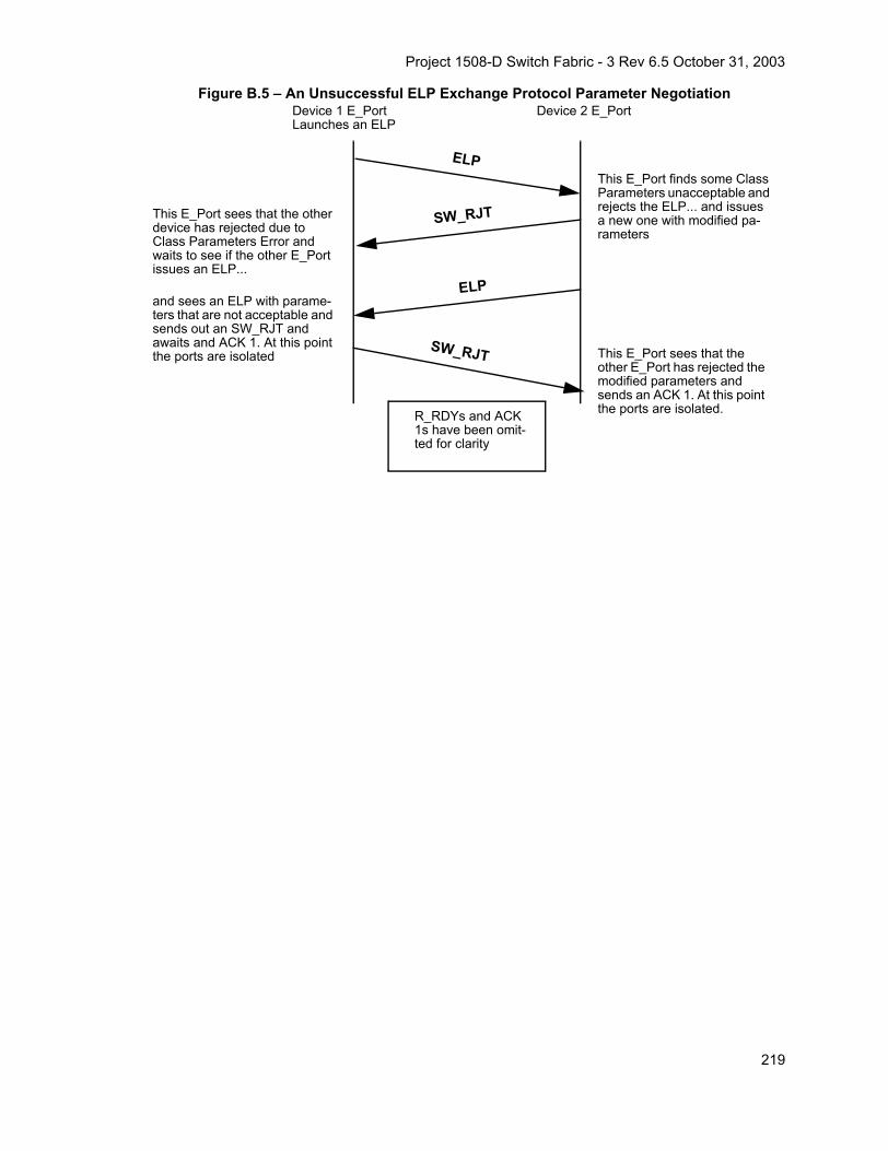
Project 1508-D Switch Fabric - 3 Rev 6.5 October 31, 2003
Figure B.5 – An Unsuccessful ELP Exchange Protocol Parameter Negotiation
ELP
SW_RJT
SW_RJT
ELP
This E_Port sees that the other device has rejected due to Class Parameters Error and waits to see if the other E_Port issues an ELP...
Device 1 E_Port Launches an ELP
Device 2 E_Port
R_RDYs and ACK 1s have been omit-ted for clarity
and sees an ELP with parame-ters that are not acceptable and sends out an SW_RJT and awaits and ACK 1. At this point the ports are isolated
This E_Port finds some Class Parameters unacceptable and rejects the ELP... and issues a new one with modified pa-rameters
This E_Port sees that the other E_Port has rejected the modified parameters and sends an ACK 1. At this point the ports are isolated.
219

Project 1508-D Switch Fabric - 3 Rev 6.5 October 31, 2003
B.3 Summary of Responses to ELP
Table B.1 below summarizes the responses sent to the ELP Request originator. Table B.1 also sum-marizes further actions at the ELP Request originator.
Table B.1 – Responses to an ELP Request InitiatorResponses Sent to the
Originator Indication Further Originator Action
R_RDY Request received at destination Wait E_D_TOV for response
ACK_1 Request received at destination Wait E_D_TOV for response
SW_ACC ELP parameters acceptable Send ACK_1
F_BSY Destination is busy Retry after time-out period
F_RJT Frame is Not Acceptable Respond accordingly as defined in FC-FS; retry may be appropriate
(Both send ELP at same time) (recvd Switch_Name) =
(own Switch_Name)E_Port is looped back to input Remove loopback connection
ELPs crossover (revd Switch_Name) < (own Switch_Name)
Send SW_RJT with Reason Code: Command already in progress
ELPs crossover (revd Switch_Name) >(Own Switch_Name)
Receive an SW_RJT and process the received ELP and send out an accept or reject
SW_RJT;a new ELP may now be
issuedReason code/explanation: Wait for ELP
E_D_TOV expires Destination is busy; or ELP, SW_ACC, ACK_1 lost Retry after a time-out period
220

Project 1508-D Switch Fabric - 3 Rev 6.5 October 31, 2003C Login BB_Credit Examples
Annex C(informative)
Fabric Device Management interface-Sample Flows
C.1 Introduction
This annex presents sample flows for the Fabric Device Management Interface (FDMI).
C.2 Sample FlowsC.2.1 HBA Registration - Single Switch
In Figure C.1 below, the switch interactions are shown for HBA registration to a single switch.
1) The HBA attempts registration by sending an RHBA to Switch 1. Since the HBA has not alreadyregistered with Switch 1, the registration completes successfully and Switch 1 becomes the HBA’s pri-mary manager.
2) Switch 1 sends a Registration Notification to Switches 2 and 3. Switches 2 and 3 now update theircaches such that subsequent queries to Switches 2 and 3 regarding the HBA may be handled locally.
3) Some time later the HBA requests registration by sending an RHBA through another port to Switch1. This time the registration fails because the HBA is already registered with Switch 1. Since the HBAhas not registered with any other switches, Switch 1 becomes the HBA’s primary manager.
Figure C.1 – Registration of HBA Information - Single Switch
HBA
Switch 1
Switch 2
Switch 3
1
3
2
2
221

Project 1508-D Switch Fabric - 3 Rev 6.5 October 31, 2003
C.2.2 HBA Registration - Multiple Switches - Caches Updated
In Figure C.2 below, the switch interactions are shown for HBA registration to multiple switches whenthe caches are updated.
1) The HBA attempts registration by sending an RHBA to Switch 1. Since the HBA has not alreadyregistered with Switch 1, the registration completes successfully.
2) Switch 1 sends a Registration Notification to Switches 2 and 3. Switches 2 and 3 now update theircaches such that subsequent queries to Switches 2 and 3 regarding the HBA may be handled locally.
3) Some time later the HBA requests registration by sending an RHBA through another port to Switch3. Switch 3 performs the checks against its FDMI database and its cached information. The cachedinformation indicates that the HBA has already been registered in Switch 1 and the registration is re-jected. Switch 1 becomes the HBA’s primary manager.
Figure C.2 – Registration of HBA Information - Multiple Switches Caches Updated
C.2.3 HBA Registration - Multiple Switches - Caches Not Updated
In Figure C.3 below, the switch interactions are shown for HBA registration to multiple switches whenthe caches are not updated.
1) The HBA attempts registration by sending an RHBA to Switch 1. Since the HBA has not alreadyregistered with Switch 1, the registration completes successfully.
2) Before Switch 1 sends a Registration Notification to Switches 2 and 3, the HBA requests registrationby sending an RHBA through another port to Switch 3. Since Switch 3 does not have an updatedcache, Switch 3 assumes that the HBA is not registered and accepts the registration.
3) Switch 1 sends a Registration Notification to Switches 2 and 3.
HBA
Switch 1
Switch 2
Switch 3
1 2
23
222

Project 1508-D Switch Fabric - 3 Rev 6.5 October 31, 2003
4) Switch 3 send a Registration Notification to Switches 1 and 2.
In this case Switch 1 has the lowest Switch_Name. Switch 2 receives the Registration Notification fromSwitches 1 and 3 and notes that Switch 1 has the lower Switch_Name. Switch 2 updates his cachewith the information received from Switch 1 and designates Switch 1 has the primary manager for theHBA. Switch 3 receives the Registration Notification from Switch 1 and notes that Switch 1 has thelower Switch_Name. Switch 3 deletes the HBA information from its FDMI database and updates hiscache with the information received from Switch 1. Switch 3 designates Switch 1 as the primary man-ager for the HBA.
Figure C.3 – Registration of HBA Information - Multiple Switches Caches Not Updated
C.2.4 HBA De-Registration - Primary HBA Manager
In Figure C.4 below, the switch interactions are shown for HBA De-Registration to the primary HBAmanager.
1) The HBA attempts de-registration by sending an DHBA to Switch 1. Since Switch 1 is the primaryHBA manager, the de-registration completes successfully and the HBA information is removed fromSwitch 1’s FDMI database.
2) Switch 1 sends a De-registration Notification to Switches 2 and 3. Switches 2 and 3 now delete theHBA’s information from their caches.
HBA
Switch 1
Switch 2
Switch 3
1 3
32
4
4
223

Project 1508-D Switch Fabric - 3 Rev 6.5 October 31, 2003
Figure C.4 – HBA De-Registration - Primary HBA Manager
C.2.5 HBA De-Registration - Non-Primary HBA Manager
In Figure C.5 below, the switch interactions are shown for HBA De-Registration to a switch that is notthe primary HBA manager. In this case, Switch 1 in the primary manager for the HBA and the HBA isconnected to Switch 1 and Switch 2.
1) The HBA attempts de-registration by sending an DHBA to Switch 2. Since Switch 2 is not the pri-mary manager for the HBA Switch 2, it is required to inform Switch 1 of the de-registration request.
2) Switch 2 sends a De-Registration Forward to Switch 1 which is the HBA’s primary manager. Switch1 de-registers the HBA information and deletes the information from its FDMI database.
3) Switch 1 sends a De-registration Notification to Switches 2 and 3. Switches 2 and 3 now delete theHBA’s information from their caches.
HBA
Switch 1
Switch 2
Switch 3
1
2
2
224

Project 1508-D Switch Fabric - 3 Rev 6.5 October 31, 2003
Figure C.5 – HBA De-Registration - Non-Primary HBA Manager
HBA
Switch 1
Switch 2
Switch 3
12
3
3
225

Project 1508-D Switch Fabric - 3 Rev 6.5 October 31, 2003
226