
02chapters1-4
118
Chapter 1: Thesis Overview 1 Chapter 1 Thesis Overview 1.1 Introduction Substation Automation (SA) is a supervisory management and control system for industrial electrical distribution systems. The interest on SA has been increasing rapidly due to its numerous benefits to utilities. It has advanced further than a traditional Supervisory Control and Data Acquisition (SCADA) system providing additional capability and information that can be used to further improve operations, maintenance and efficiencies in substations [8]. The most significant elements of a SA system include relays and/or Intelligent Electronic Devices (IEDs) that perform various control, monitoring and protection related operations. The success of a SA system relies heavily on the use of an effective communication system to link the various control, monitoring and protection elements within a substation. There are large numbers of protocols for communication, a matter that has lead to the problem of devices from different manufacturers and even devices from different generations from the same manufacturer not being able to communicate with each other or only with disproportionate expenditure. Standardisation is the key for the advancement of the connectivity and interoperability within a system. Through
Transcript of 02chapters1-4

8/8/2019 02chapters1-4
http://slidepdf.com/reader/full/02chapters1-4 1/118
Chapter 1: Thesis Overview
1
Chapter 1
Thesis Overview
1.1 Introduction
Substation Automation (SA) is a supervisory management and control system for
industrial electrical distribution systems. The interest on SA has been increasing rapidly
due to its numerous benefits to utilities. It has advanced further than a traditional
Supervisory Control and Data Acquisition (SCADA) system providing additional
capability and information that can be used to further improve operations, maintenance
and efficiencies in substations [8]. The most significant elements of a SA system
include relays and/or Intelligent Electronic Devices (IEDs) that perform various control,
monitoring and protection related operations.
The success of a SA system relies heavily on the use of an effective communication
system to link the various control, monitoring and protection elements within a
substation. There are large numbers of protocols for communication, a matter that has
lead to the problem of devices from different manufacturers and even devices from
different generations from the same manufacturer not being able to communicate with
each other or only with disproportionate expenditure. Standardisation is the key for the
advancement of the connectivity and interoperability within a system. Through

8/8/2019 02chapters1-4
http://slidepdf.com/reader/full/02chapters1-4 2/118
Chapter 1: Thesis Overview
2
standardisation, both users and suppliers arrive at economically suitable and reliable
solutions. For the last decade, there has been lot of work done on standardising the
language of communication between IEDs and relays [9-10]. As a result, two main
protocols have evolved: the existing Utility Communication Architecture (UCA) [9] and
the new International Electrotechnical Commission (IEC) 61850 [10]. The latter is
expected to dominate the communications in the substation environment in the near
future.
IEC 65850 is an international standard for substation automation that has started out as
the Electric Power Research Institute’s (EPRI’s) UCA 2.0. IEC 61850 is bound to have
a significant impact on how electric power systems are to be designed and built for
many years to come. It effectively reduces the diversity and complexity of utility
automated solutions minimising operating, maintenance and engineering costs. The
model-driven approach of the IEC 61850 standard describes the communication
between devices in a substation and the related system requirements. It supports all
substation functions and their engineering by using Object-Oriented (OO) data models
that describe the processes to be implemented and controlled, e.g. the functionality of a
circuit breaker or a feeder equipment etc. The use of the OO approach gives more
flexibility to the developer and the user simplifying engineering tasks. IEC 61850
contains device models that describe the properties and allocation of functions in a
physical device. In addition to the OO data models, it defines a set of generic services
for the client/server interactions between devices in a substation and also for the transfer
of all sorts of data with regards to diverse transmission requirements such as speed,
reliability and security. The Generic Object Oriented Substation Event (GOOSE) is
widely accepted as the most important one of the data transmission services defined in

8/8/2019 02chapters1-4
http://slidepdf.com/reader/full/02chapters1-4 3/118
Chapter 1: Thesis Overview
3
IEC 61850. GOOSE is a fast connection-less communication service used for the
transfer of time-critical data where high speed and security are achieved by the
repetition of messages a number of times.
One of the most significant architectural constructs of the IEC 61850 is the adoption of
an “abstracting” technique, which involves the creation of objects that are independent
of any underlying protocol. The isolation of the information models and information
exchange services from the underlying on-the-wire protocols is usually seen as one of
the most powerful capabilities of the IEC 61850 standard. The abstract nature of the
definitions permits the mappings of the data objects and services to any other protocol,
which provides adequate communication procedures meeting the data and service
requirements of the IEC 61850 standard [11]. Currently, IEC 61850 only specifies
mappings on a communication stack that includes the Manufacturing Message
Specification (MMS) over the Transmission Control Protocol/Internet Protocol
(TCP/IP) and Ethernet. However, the potential need to support mappings to different
communication models has clearly been recognised in the industry and examples do
exist in the literature detailing such mappings.
Middleware is a software layer that resides between the operating system and the
applications on each system site with the function of mediating interactions between
applications running on different machines [6]. The use of a middleware architecture
that is specifically adapted to the constraints that the Telecontrol world imposes in
accordance with the IEC 61850 standard has numerous benefits such as reduced
development time and increased interoperability, portability and reusability of
distributed electrical systems [12].

8/8/2019 02chapters1-4
http://slidepdf.com/reader/full/02chapters1-4 4/118
Chapter 1: Thesis Overview
4
1.2 Aim of This Research
The overall goal of this research is the OO implementation of the IEC 61850 standard as
a concrete application layer protocol running above a middleware layer specifically
designed and implemented in a real-time communication processor environment to
support all the communication needs required by the standard. The term
“communication processor” is referred to a device, which has a set of network protocol
layers that work together in controlling the connection, communication and data transfer
between two computing endpoints. In this research, the software based design and
implementation of various layers of a communication processor protocol stack is
described. The specific tasks to achieve a successful completion of this research are:
• Object-oriented implementation of the IEC 61850 standard : This task involves the
OO implementation of the IEC 61850 Abstract Communication Service Interface
(ACSI) Object and Service Models (OSMs) as concrete programs. The
implementation of the ACSI OSMs based on their published definitions in the
standard involves a two-stage procedure. First the OSMs that form the standard’s
application-view constituent are implemented followed by those, which form the
standard’s device-view constituent. The main aim is therefore the transformation of
the IEC 61850 standard from an abstract nature into a solid protocol with the
development of the smaller components forming the standard. Overall, a standard
C/C++ language based implementation is proposed.
• Design and implementation of IEC 61850 application layer modules: This task is
primarily centred on the design and implementation of two application layer

8/8/2019 02chapters1-4
http://slidepdf.com/reader/full/02chapters1-4 5/118
Chapter 1: Thesis Overview
5
modules as part of a communication processor protocol stack where IEC 61850
client and server applications can be modelled and configured. The software based
design and implementation of two application layer modules is presented for this
purpose, one where ACSI clients can be constructed and the other where ACSI
servers can be constructed. The designed modules permit the use of the developed
OSMs from the first task when constructing various representations of real devices
at the application layer.
• Design and implementation of a data delivery network middleware: This task
includes the design and implementation of a data delivery network middleware, the
IEC-MOM, as a separate module between the application and network access layers
of a communication processor. The designed Message-Oriented Middleware
(MOM) architecture enables IEC 61850 processes running on different machines to
interact over a network by providing various communication procedures for the
transmission of IEC 61850 related messages. It supports all messages types
specified by the IEC 61850 standard and incorporates various communication
techniques such as unicast and multicast providing a unique stand-alone
communication interface to the IEC 61850 processes running at the application layer
of the same communication processor. It also considers stringent IEC 61850 specific
Quality of Service (QoS) requirements such as the need of repeating GOOSE
messages a number of times to achieve higher reliability and integrates solutions in
its architecture for such requirements.
• Implementation and incorporation of a time synchronisation protocol into the
communication processor architecture: Time Synchronisation (TS), which involves

8/8/2019 02chapters1-4
http://slidepdf.com/reader/full/02chapters1-4 6/118
Chapter 1: Thesis Overview
6
the harmonisation of the local clocks of all communicating nodes within a network,
is also crucial in time-sensitive substation applications. This task focuses on the
implementation of a Commercial off-the Shelf (COTS) TS protocol, the Simple
Network Time Protocol (SNTP), and its incorporation into ACSI applications. The
SNTP is implemented making use of the Object Oriented Programming (OOP)
techniques and SNTP client applications are integrated into the designed ACSI
application layer modules. On the other hand, SNTP server applications are
configured in stand-alone communication processors. The IEC-MOM middleware is
also modified such that it provides support for the SNTP request/reply messages as
well as the QoS requirements concerned with TS applications. An adaptive filtering
technique and a lower-layer time stamping technique are proposed and demonstrated
to be beneficial in meeting the TS accuracy requirements imposed by the IEC 61850
standard.
• Design and implementation of a “Hardware in the LOOP” (HITL) capability: The
objective of this task is to develop a capability that will permit for the testing of the
designed components over a real network. The proposed HITL capability acts as a
gateway between the simulation environment and the real Ethernet network
establishing a link between the virtual simulation and the real network and enabling
message passing between the two.
1.3 Research Methodologies and Techniques
This research targets the implementation of the IEC 61850 standard with the
development of its OO models transforming it into a concrete application layer protocol

8/8/2019 02chapters1-4
http://slidepdf.com/reader/full/02chapters1-4 7/118
Chapter 1: Thesis Overview
7
that runs on exclusively designed middleware architecture. The design, implementation,
simulation and testing of various components will be carried out using appropriate
software development and network design tools. The details of proposed methodology
and techniques to achieve the requirements of this research project are as follows:
(i) Literature review
To start with, the IEC 61850 standard is to be examined in detail as well as identifying
the most appropriate software development technique to achieve the successful
implementation of the standard. The communication requirements set by the IEC 61850
standard will be investigated and the currently available communication architectures
will be analysed in order to recognise their strengths and weaknesses. Finally, the exact
detailed specifications for the middleware architecture will be drawn.
(ii) Implementation of the IEC 61850 standard
Implementation of the IEC 61850 standard is at the core of this research. Several
components of the standard need to be examined, assessed and implemented based on
their OO definitions. The OO features of the C++ programming language, its popularity
and widespread use in engineering applications make it the most suitable candidate for
this task. Therefore, this task will be carried out using Microsoft Visual C++ 6.0, which
is part of Microsoft’s software development suite, the Visual Studio.
(iii) Design and implementation of IEC 61850 application layer modules
Once all the building blocks of the IEC 61850 standard are developed, two application
layer modules will be designed and implemented using a suitable network simulation &

8/8/2019 02chapters1-4
http://slidepdf.com/reader/full/02chapters1-4 8/118
Chapter 1: Thesis Overview
8
design package. Optimised Network Engineering Tools (OPNET) has been chosen for
this purpose, which is an OO discrete-event network simulator allowing for the
modelling, implementation, simulation and performance analysis of communication
networks and distributed applications.
(iv) Design and implementation of the middleware architecture
The design and implementation of a data delivery network middleware architecture with
respect to the identified design constraints needs to follow and will be carried out once
more making use of the OPNET network simulation & design package. Once this task is
concluded, the overall communication system will be tested with regards to the
identified communication requirements to evaluate the performance of the designed
architecture in terms of speed, reliability and efficiency.
(v) Implementation of the time synchronisation protocol
This task comprises a two-stage procedure. First, the software development of various
components of the SNTP TS protocol needs to be accomplished followed by the
incorporation of the developed components into the designed application layer modules
where TS processes can be modelled and constructed. Once successfully completed,
simulations will be carried out to test the overall design with respect to TS accuracy
requirements.
(vi) Design and implementation of the HITL capability
This task will be accomplished using Windows Winsock mechanisms jointly with
OPNET. It involves the design and implementation of gateway modules, which will act

8/8/2019 02chapters1-4
http://slidepdf.com/reader/full/02chapters1-4 9/118
Chapter 1: Thesis Overview
9
as converters between the virtual simulation environment and the real Ethernet network.
Once completed, the overall design will be tested for a real network scenario involving
the use of real Ethernet links, switches, routers, etc.
1.4 Originality of the Thesis
This research will contribute to the knowledge in substation communication system
design since it tackles major issues related to standardisation efforts and establishment
of open and standard working environments following the path initiated by the UCA
2.0. This research will contribute to knowledge in the following specific areas:
(1) Contributes to the knowledge by addressing a previously neglected area that is
the transformation of the IEC 61850 standard into a solid application layer
protocol with the development of concrete programs for the standard’s
application and device-view OSMs. No other such OO implementation of the
standard exists in the literature other than implementation through the mapping
processes. The proposed research will be immensely beneficial to power
protection and control engineers since it further enhances the understanding of
the IEC 61850 standard and simplifies its use by illustrating how the OO models
discussed in the standard can as well be implemented using the OOP techniques.
This research is significant since it fully isolates the standard from the
underlying protocols by providing a standard universal OO implementation
removing the standard’s dependency on the mapping process.
(2) Contributes to the knowledge by identifying the critical issues behind the
development and design of a specific communication service aimed at providing

8/8/2019 02chapters1-4
http://slidepdf.com/reader/full/02chapters1-4 10/118
Chapter 1: Thesis Overview
10
all sorts of communication mechanisms to IEC 61850 based applications
running within substations. This research is significant since it proposes a
middleware architecture that integrates all required message distribution
mechanisms in its architecture eliminating the need for the multiple
communication service mappings that exists as a burden in the existing IEC
61850 standard. The proposed middleware only provides a communication
interface to IEC 61850 and does not include any object or service models.
(3) The proposed research is significant since it further integrates a TS protocol into
the communication processor architecture, which makes it possible to harmonise
the local clocks of all the communicating IEDs within a substation network
relative to a chosen reference so that sensing and actuation of time-sensitive data
can be coordinated accurately across multiple nodes.
(4) Contributes to knowledge by describing a preliminary work carried out to
demonstrate how the software design can be interfaced to a real network.
1.5 Organisation of the Thesis
This thesis contains eight chapters and is organised as follows:
Chapter 1 has provided a basic introduction about the research as well as the aims of
this research, the research methodologies and techniques and the contribution of this
research to the knowledge. Chapter 2 presents a literature review of power system
communications, recent standardisation developments and the use of protocols and
middleware architectures in substations. Previous and current trends of middleware

8/8/2019 02chapters1-4
http://slidepdf.com/reader/full/02chapters1-4 11/118
Chapter 1: Thesis Overview
11
technologies are discussed highlighting the importance of middleware in the strategy of
establishing an open and standard working environment.
The development implications and implementation details of all application-view
constituent components of the IEC 61850 standard are presented in Chapter 3. The
typical building blocks of the IEC 61850 application view comprise logical nodes, data,
data sets, etc., where logical nodes are the key elements comprising all other building
blocks. In-dept study of the standard and the use of OOP techniques and methodologies
in the implementation of various ACSI OSMs are presented. Chapter 4 looks at the
modelling and implementation aspects of the standard’s device-view constituent
components such as logical devices.
Chapter 5 presents the software based design and implementation of the various
protocol layers of a communication processor stack including the application layer
modules and the middleware architecture. The design and implementation details of
these components are individually discussed. Performance analysis of the overall
communication system will be considered to justify proper function of the designed
components as well as the appropriateness of design techniques and methodologies.
The implementation of the SNTP and its incorporation into the overall architecture is
discussed in Chapter 6 along with performance analysis indicating the effectiveness of
the design in meeting the time synchronisation accuracy requirements. Chapter 7 covers
the development of a HITL capability focusing on the design and implementation
details as well as performance analysis. The conclusions and future scope for this
research are discussed in Chapter 8.

8/8/2019 02chapters1-4
http://slidepdf.com/reader/full/02chapters1-4 12/118
Chapter 2: Literature Review
12
Chapter 2
Literature Review
2.1 Introduction
The purpose of this chapter is to provide the necessary background required to
understand the concepts that relate to power system communications, recent
standardisation developments and the use of protocols and middleware architectures in
substations. When designing any type of middleware, it is important to learn from past
research experience, which has resulted in many contrasting middleware technologies
with different strengths and weaknesses [13]. The evolution of the recent standards such
as UCA 2.0 and IEC 61850 will eventually lead to the replacement of various existing
proprietary solutions with a standard communication approach for all future equipment
from all around the world [14, 15]. The use of middleware technologies is fundamental
to the strategy of establishing an open and standard working environment
complementing the works of the standardisation developments.
Consequently, this chapter is structured in a similar fashion starting with an overview of
power system devices in Section 2.2 followed by the discussion of power system’s
automation, integration and communications aspects in Section 2.3. Subsequently, in
Section 2.4, protocols are discussed in general and with regards to power systems.

8/8/2019 02chapters1-4
http://slidepdf.com/reader/full/02chapters1-4 13/118
Chapter 2: Literature Review
13
Section 2.5 discusses the recently developed application layer protocols. The chapter
follows with Section 2.6, which reviews the state-of-the-art middleware architectures
with special attention given to their use in power system communications.
2.2 Intelligent Electronic Devices
Many of today’s electric utility substations include digital relays and other Intelligent
Electronic Devices (IEDs) that record and store a variety of data in relation to their
control interface, internal operation and about the power system they monitor, control
and protect. Instrumentation & Control (I&C) devices, which are built using
microprocessors, are commonly referred to as IEDs. Microprocessors are single-chip
computers that can process data, accept commands and communicate information.
Nowadays, digital relays are widely replacing the aging electromechanical and solid-
state electronic component-type relays and relay systems [16].
Figure 2.1 shows a digital relay with its target interfaces. Digital relay’s popularity
comes from their low price, reliability, functionality and flexibility. However, the most
important feature that separates a digital relay from previous devices is its capability of
collecting and reacting to data and then using this data to create information. Such
information includes [16, 17]:
Figure 2.1 Digital relay with target interfaces [16]

8/8/2019 02chapters1-4
http://slidepdf.com/reader/full/02chapters1-4 14/118
Chapter 2: Literature Review
14
• Protection Data: Fault location and fault type,
• Metering Data: Pre-fault, fault and post-fault currents and voltages,
• Breaker and relay operation data, and
• Diagnostic and historical data [18].
IEDs can also run automatic processes while communications are handled through a
serial port similar to the communication ports on a computer. Some examples of IEDs
used in a power system are [19]:
• Instrument transformers,
• Remote Terminal Units (RTUs), and
• Digital fault recorders.
2.3 Automation, Integration and Communications
Power system automation is the act of automatically controlling the power system via
I&C devices whereas Substation Automation (SA) refers to the use of IED data and
control commands from remote users to control the power system devices within a
substation. Power system integration, on the other hand, refers to communicating data
to, from, or amongst IEDs in an I&C system. Finally, Substation Integration (SI) stands
for combining IEDs’ local data in a substation so that there is a single point of contact in
the substation for all of the I&C data [19, 20].
The performance of power systems have always been improved with the use of
communication principles. Without the use of a proper communication channel, power
system protection suffers from a major disadvantage of not being able to accurately

8/8/2019 02chapters1-4
http://slidepdf.com/reader/full/02chapters1-4 15/118
Chapter 2: Literature Review
15
UCA Gateway
Legacy IED
IED IED
EthernetHub
Router
Substation HMI
WAN
SCADAMaster
LaptopComputer
DataConcentrator
TerminalServer
TerminalServer
EngineeringStation
RS 485
RS 485
RS 485 RS 485
Ethernet Ethernet
RS 232
RS 232
diagnose faults. When voltages and currents are analysed only from one terminal, it
cannot be concluded whether a fault near the far end terminal is internal or external to
the protected line segment. This requires delayed tripping for such faults, which can
endanger system stability or increase vulnerability. At the far end terminal, the decision
whether the fault is internal or external is obvious not from a distance measurement but
from the knowledge of the direction of the fault. This information can be transmitted to
the other terminal enabling it to decide whether to send signal to trip or not to trip [21].
Power utilities are focused on increasing productivity and making electric power safer,
more reliable and economical by providing innovative, simple to use and robust
technologies. Development of appropriate communication technologies and protocols is
at the heart of this strategy. When relays and IEDs are integrated together, they form a
powerful and economical I&C system capable of supporting all aspects of electric
power protection, automation and control [22]. Figure 2.2 shows how IEDs and relays
can be interconnected together forming protection schemes for power systems.
Figure 2.2 Typical integrated substation protection and control system [23]

8/8/2019 02chapters1-4
http://slidepdf.com/reader/full/02chapters1-4 16/118
Chapter 2: Literature Review
16
The relaying and measurement tasks have been well understood and standardised. On
the other hand, the technical methods and operating impact of data communications
continue to evolve dramatically. There is a wide variety of incompatible communication
approaches and systems in the marketplace. Competing manufacturers have been
following unique approaches when designing their communication interface circuits. As
a result, the users could not directly interconnect competing products and had to provide
a different communication system for each vendor. However, the use of competing
products from different vendors offers a variety of protection and monitoring
capabilities for users although they are often frustrated by the communication related
variations [15].
The desire and the need of merging the communication capabilities of all relays and
IEDs in a substation has thus been clearly recognised, which is capable of providing not
only data gathering and setting capability but also remote control. Furthermore, multiple
IEDs can share data or control commands at higher speeds to perform new distributed
protection and control functions [15]. Interoperability [24, 25] needs to be achieved in a
substation between protective relays from different manufacturers so that substation
level interlocking, protection and control functions can be realised improving the
efficiency of microprocessor based relay applications [26].
For the last few years, the advancements in microprocessor based IEDs networked over
high-speed communication networks using standardised communication protocols is
leading the evolution of power system control technology. The introduction of UCA 2.0
and IEC 61850 has made it possible and justifiable to integrate station IEDs on a high-
speed peer-to-peer communication network (Ethernet) through standardisation. The use

8/8/2019 02chapters1-4
http://slidepdf.com/reader/full/02chapters1-4 17/118
Chapter 2: Literature Review
17
of existing standards and commonly accepted communication principles together with
the new standards such as IEC 61850 and UCA provides a solid base for interoperability
leading to more flexible and powerful protection and control systems [27].
2.4 Protocols
A protocol is basically a set of rules that must be obeyed for orderly communication
between two or more communicating parties [28]. The International Standards
Organisation (ISO) has divided the communication process into seven basic layers as
shown in Figure 2.3, which is commonly referred to as the Open Systems
Interconnection (OSI) model [28-30].
Figure 2.3 The OSI reference model
Each level operates independently of the others and has a certain function to perform.
However, the successful operation of one level is mandatory for the successful
operation of the next level. These layers define how data flows from one end of a
Application Layer
Presentation
Layer
Session Layer
Transport Layer
Network Layer
Data Link Layer
Physical Layer
Information Processing
Functions
Communications Functions
Application Layer
Presentation
Layer
Session Layer
Transport Layer
Network Layer
Data Link Layer
Physical Layer
The Physical Media of the OSI

8/8/2019 02chapters1-4
http://slidepdf.com/reader/full/02chapters1-4 18/118
Chapter 2: Literature Review
18
communication network to another and vice versa. Two devices can only communicate
if each layer in the model at the sending device matches with each layer in the model at
the receiving device [29, 30]. Communication between data processing systems from
different manufacturers has often been particularly difficult due to the fact that there has
been separate development of data processing and data communication techniques,
often resulting in complex and expensive interfaces.
2.4.1 The Ethernet Protocol
The Ethernet protocol [31, 32], a network concept illustrated in Figure 2.4, is one of the
most widely used data link layer protocols designed for carrying blocks of data called
frames as described by the IEEE 802.3 standard [33]. Ethernet uses an access method
called Carrier Sense Multiple Access/Collision Detection (CSMA/CD) [33], which is a
system where each host listens to the medium before transmitting any data to the
network.
Figure 2.4 The Ethernet network concept [34]
If the network is clear, the host will transmit. However, if some other node is
transmitting, it will wait and try again when the network becomes clear. Collisions
occur when two hosts try to transmit at the same instant forcing each other to back off

8/8/2019 02chapters1-4
http://slidepdf.com/reader/full/02chapters1-4 19/118
Chapter 2: Literature Review
19
and wait a random amount of time before attempting to re-transmit. Although collisions
affect the total throughput, the delay caused by the re-transmissions is very small
normally not affecting the speed of transmissions on the network. Ethernet allows for
the transmission of data from a speed of 10 Mbps to 1000 Mbps [35].
2.4.2 The TCP/IP Internet Protocol Suite
The Internet Protocol (IP) is a network layer protocol, which uses datagrams to
communicate over a packet-switched network [36, 37]. It provides datagram services
for transport layer protocols such as Transmission Control Protocol (TCP) and User
Datagram Protocol (UDP). It is one of the subset protocols of the TCP/IP suite as
illustrated in Figure 2.5.
Figure 2.5 TCP/IP protocols and functional layers [26]
The IP forms a computer network by connecting computers assigning each one a unique
IP address [38]. Each IP packet carries an IP address [39], which consists of two parts: a
destination address and a host address. The host address is the IP address of the sending
computer, whereas the destination address is the address of the recipient or recipients of
OSI layers TCP/IP layers TCP/IP examples
Application
Presentation
Physical
Data Link
Network
Transport
Session
Application
Transport
Internet
Network interface and
hardware
Telnet FTP
SMTP Telnet
TFTPDNS
TCP UDP
ARP RARPIP
ICMP
Ethernet, token ring, FDDI drivers and hardware

8/8/2019 02chapters1-4
http://slidepdf.com/reader/full/02chapters1-4 20/118
Chapter 2: Literature Review
20
the packet. Routers, switches make use of the destination address when forwarding
packets across interconnected networks.
The major concern with IP is that it makes no attempts to determine if packets reach
their destination or to take corrective action if they do not. Therefore IP does not
provide guaranteed delivery. This problem can be avoided in some applications where a
transport protocol that carries out such a function is used. The best example for the latter
is TCP [40], which makes up for IP's deficiencies by providing reliable, stream-oriented
connections that hide most of IP's shortcomings. However, other applications requiring
best effort services (faster transmission times) usually use UDP [41], which is a simple
connection-less transport layer protocol without any real mechanisms for reliable
delivery. UDP packets are delivered the same as the IP packets and may even be
discarded before reaching their destinations.
Although the transmission of data requires the best-effort service in some substation
applications, reliability is also a major concern. The best effort service requires the use
of UDP, which has no support whatsoever for reliable transmission. This implies that
certain primitives need to be implemented to achieve higher reliability in cases where IP
is to be used alongside UDP. This is one of the major concerns being looked at in this
research with a model being proposed in this thesis to solve this problem.
2.4.3 Protocols in Substations
There are literally thousands of combinations of protocol agreements that can be created
with the large domain of existing pieces. The main protocols that have found
widespread use in the substation environment are [21]:

8/8/2019 02chapters1-4
http://slidepdf.com/reader/full/02chapters1-4 21/118
Chapter 2: Literature Review
21
• MODBUS: A popular master-slave protocol with industrial users, which has
become popular in substations. It issues simple READ/WRITE commands to
addresses inside an IED.
• Distributed Network Protocol (DNP): An increasingly popular master-slave
protocol mainly used in North America. DNP can run over multiple media, such
as RS-232 and RS-485 and can issue multiple types of READ/WRITE messages
to an IED.
• IEC-870-5-101: is considered as the European partner to DNP. It differentiates
itself from DNP with its slightly different messaging structure and the ability to
access object information from the IED.
2.5 Standardisation Developments
The introduction of higher-level protocols in IEDs has only enabled communication
between devices from the same manufacturer. However, the potential to communicate
between varieties of devices from different vendors enables utilities with a variety of
protection, monitoring and automation capabilities. Currently, this can only be achieved
with the use of protocol converters or gateways. Worldwide, electric utility deregulation
has expanded and created demands to integrate, consolidate and disseminate real-time
information quickly and accurately with and within substations [27, 42]. Hence, a non-
proprietary and high-speed protocol was required to facilitate a robust and integrated
substation communication network by standardising the language of communication
within substation. Using the standardised high-speed communication between IEDs,
utility engineers can eliminate many expensive stand-alone devices and use the
sophisticated functionality and available data to their full extent [27]. The utilities are

8/8/2019 02chapters1-4
http://slidepdf.com/reader/full/02chapters1-4 22/118
Chapter 2: Literature Review
22
aimed at creating a framework for not only common communication but also an
architecture that will provide for interoperability. The ability to “plug and play” is
referred to as interoperability, also meaning to be able to “share” data and functions
[24].
UCA [9] was commissioned by the EPRI in 1994 to identify the requirements, overall
structure and specific communication technologies to implement the standardisation
scheme. The adopted approach defined the technical requirements for a system to
control and monitor substations of any size [15]. The Technical Committee (TC) 57 of
the IEC began work on IEC 61850 [10] in 1996 with a similar target. In 1997, the two
groups joined together to define a common international standard that would combine
the work of both groups. The result of the harmonisation process is the IEC 61850
standard, which is a superset of UCA 2.0 as shown in Figure 2.6 while offering some
additional features [43].
Figure 2.6 The merging process [43]
2.5.1 The UCA Substation Communications Project
UCA targets to reduce the engineering, monitoring, operation and maintenance costs
while increasing the agility of the whole life cycle of a substation by improving device
data integration into the information and automation technology [44]. Many relay and
IED manufacturing companies showed their interest in UCA work and joined in the

8/8/2019 02chapters1-4
http://slidepdf.com/reader/full/02chapters1-4 23/118
Chapter 2: Literature Review
23
effort to define and demonstrate a communication network stack [15]. With continued
EPRI support, vendors have built UCA-compliant versions of their products. The
equipment makers continue to modify and update the implementations in each of the
products. Many US and overseas utilities have signed up to demonstrate UCA
substation systems. The users can see an impressive and elaborate demonstration of
interoperability amongst a broad variety of equipment from competing manufacturers in
meetings held several times a year. The importance of achieving interoperable
communication has forced collegial cooperation among competitors, who see the
individual-product features and performance as the proper ground for competition [45].
The UCA is comprised of data object models, service interfaces to these models and
communication profiles as illustrated in Figure 2.7 [44]. Data object models are at the
highest level, i.e. at the application layer. Service interfaces include operations such as
defining, retrieving and logging of process data.
Data Objects
Service Interface
CommunicationProfiles
Data
Device
How to describe data/devices ?How to access?
Communication channels ?
Data on the wireData
Figure 2.7 Three levels of UCA [44]
Within the UCA framework, a device object model is referred to as the definition of
data and control functions made available by the device along with the associated

8/8/2019 02chapters1-4
http://slidepdf.com/reader/full/02chapters1-4 24/118
Chapter 2: Literature Review
24
algorithms and capabilities [9]. Device models describe the communication related
behaviour of devices by making use of a common set of services. The detailed
interoperable structure for utility field devices can be fully specified by mapping these
services onto the UCA Application Layer Protocol (ALP) when used in conjunction
with the device models. The services and their mappings to the Manufacturing Message
Specification (MMS) are defined in UCA Common Application Service Models
(CASM) [46]. Device models can be specified independent of the underlying protocol.
Active participation of groups outside the UCA activities has been encouraged due to
this feature of protocol independence, which also simplifies migration through the
construction of getaways to older existing protocols [44-46].
2.5.2 IEC 61850 Project
IEC 61850 is based on the need and opportunity for developing standard
communication protocols to permit interoperability of IEDs from different
manufacturers [47, 48]. IEC 61850 makes use of existing standards and commonly
accepted communication principles, which allows for the free exchange of information
between IEDs. It focuses on neither standardising the functions involved in substation
operations nor their allocation within the substation automation systems. It only
identifies and describes impact of the operational functions on the communication
protocol requirements [27]. IEC 61850 allows applications to be designed independent
from the communication theory enabling them to communicate using different
communication protocols. Therefore, it provides a neutral interface between application
objects and their related application services as shown in Figure 2.8 allowing a
compatible exchange of data among components of a SA system [27].

8/8/2019 02chapters1-4
http://slidepdf.com/reader/full/02chapters1-4 25/118
Chapter 2: Literature Review
25
Application
SCSM 1 SCSM nSCSM 2
AL 1 AL 2 AL n
Layers 1-6
Application Layer
ACSI- AbstractCommunicationService Interface
Specific CommunicationService Mapping
Neutral Interface
Specific Interfaces
Figure 2.8 The basic reference model [27]
One of the most important features of IEC 61850 is that it covers not only
communication, but also qualitative properties of engineering tools, measures for
quality management and configuration management. This is necessary since when
utilities are planning to build a substation automation system with the intention of
merging IEDs from different vendors, they expect not only interoperability of functions
and devices, but also a homogenous system handling [27].
IEC 61850 proposes the concept of standardising IED data using data objects referred to
as logical nodes. This makes it possible to achieve the “plug and play” capability so that
information and commands can be shared on a single network [27, 49]. By using
standardised data, it is feasible to define applications without any knowledge in relation
to the actual device itself since the data contained in the device and the data available on
the network for further use will be known up front. Hence, it becomes possible to know
the exact data present from a communication point of view provided that all logical
nodes and other data elements are implemented in line with the standard. The “plug and

8/8/2019 02chapters1-4
http://slidepdf.com/reader/full/02chapters1-4 26/118
Chapter 2: Literature Review
26
play” capability becomes possible after adding the self-description of logical nodes and
hence those of the devices [27]. The relationship between the application and
communication views of the IEC 61850 standard is shown in Figure 2.9, which
illustrates how applications can be defined using the standardised data and how this data
can be retrieved or manipulated by using a number of specific services.
A p p l i c a t i o n V i e w
C o m m u n i c a t i o n V i e w
Services by which the information can be accessed or manipulated
Communication Objects and Services according to7-2 mapped to a SCSM
Binding P r o c
e s s
Object Dictionary of a device contains all accessible
information
Objects
According to
7-4 and 7-3
Logical Node ObjectData ObjectsData Objects
Data Objects Data Objects
Network
Figure 2.9 Relationship between the application and communication interfaces [27]
With the “plug and play” capability embedded in the standard and the immediate
endorsement of the concept in pilot projects, IEC 61850 promises to be a great step
forward in the development and acceptance of substation automation systems world-
wide. This has brought the real benefits of automation and integration to utilities that
were originally promised years ago [27].
2.6 Middleware Architectures
The wide spread utilisation of object technology has enabled the use of object oriented
paradigm in distributed environments [50]. A distributed environment is a network of

8/8/2019 02chapters1-4
http://slidepdf.com/reader/full/02chapters1-4 27/118
Chapter 2: Literature Review
27
Client
Application
Middleware
Operating System
Communication
Software
<<<< TCP/IP Network >>>
Server Application
Middleware
Operating System
Communication
Software
distributed objects that seamlessly communicate with each other [51]. Distributed
objects, which can be subject of remote procedure calls, are objects distributed over the
network residing in separate address spaces [50, 52 and 53]. A typical distributed
processing environment consists of several nodes interconnected by means of a
communication network. Each node consists of a CPU and a network interface board.
In some cases where distributed systems need to operate in a heterogeneous
environment, it is high likely that different nodes will consist of different hardware and
operating systems [53]. In such cases, there is a need for a layer of software as shown in
Figure 2.10, which sits above the heterogeneous operating system in order to provide a
uniform platform about which the distributed applications can run.
Figure 2.10 Protocol stack incorporating the middleware layer
Middleware software is a layer between the networking and application codes of a
protocol stack. The function of the middleware is to insulate the application
programmer from the raw networking code thus providing an easier way to
communicate [54]. In addition, it supplies a set of common services to perform various
general purpose functions. There are two main types of middleware architectures, which
are the client/server and publish/subscribe architectures [54, 55].
8/8/2019 02chapters1-4
http://slidepdf.com/reader/full/02chapters1-4 28/118
Chapter 2: Literature Review
28
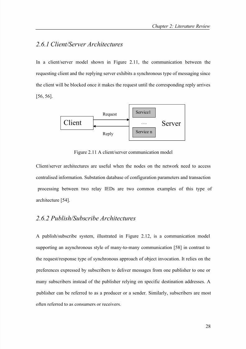
2.6.1 Client/Server Architectures
In a client/server model shown in Figure 2.11, the communication between the
requesting client and the replying server exhibits a synchronous type of messaging since
the client will be blocked once it makes the request until the corresponding reply arrives
[56, 56].
Client
Request
Reply
….
Service1
Service n
Server
Figure 2.11 A client/server communication model
Client/server architectures are useful when the nodes on the network need to access
centralised information. Substation database of configuration parameters and transaction
processing between two relay IEDs are two common examples of this type of
architecture [54].
2.6.2 Publish/Subscribe Architectures
A publish/subscribe system, illustrated in Figure 2.12, is a communication model
supporting an asynchronous style of many-to-many communication [58] in contrast to
the request/response type of synchronous approach of object invocation. It relies on the
preferences expressed by subscribers to deliver messages from one publisher to one or
many subscribers instead of the publisher relying on specific destination addresses. A
publisher can be referred to as a producer or a sender. Similarly, subscribers are most
often referred to as consumers or receivers.

8/8/2019 02chapters1-4
http://slidepdf.com/reader/full/02chapters1-4 29/118
Chapter 2: Literature Review
29
Figure 2.12 Publish/subscribe communication model
Subscribers make subscriptions using definitions of the information they are interested
in. Publishers create instances of information, which get forwarded to the subscribers of
this information. Distributed real-time communication in the substation environment
can as well be realised using the publish/subscribe communication model.
IEDs perform two main tasks in a distributed publish/subscribe system enabling direct
message exchange between the communicating IEDs. An IED will either [54]:
• Subscribe to data that it needs, or
• Publish information that it produces.
Any authorised IED may add itself as a subscriber to a particular publisher's list. That
subscribing IED will then receive the publications directly from that publisher IED as
they become available. Publish/subscribe systems are useful since [54]:
• They are good and quick distributors of large quantities of time-critical
information even when unreliable delivery mechanisms are present,
• They can handle very complex data flow patterns, and
• The many-to-many model is very efficient in both bandwidth and latency [59].
Subscriber
1
Subscriber
2
Subscriber
3
Publish
Subscribe ()
Unsubscribe ()
Push event ()
Event ServicePublisher
1
Publisher
2
Publisher
3

8/8/2019 02chapters1-4
http://slidepdf.com/reader/full/02chapters1-4 30/118
Chapter 2: Literature Review
30
One of the important properties of the publish/subscribe middleware is that the
applications running in publishers and subscribers are kept independent of each other.
The most important of all is that it handles connections, failures and changes in the
network only delivering the data that has been requested by the application software
[54]. Although the publish/subscribe model is the best option for use in distributed
substation systems, real-time substation systems have other unique needs that can not be
served by a multi-purpose designed architecture. Specific architectures are needed to
cater for the special needs and requirements of such systems. This is one of the issues
being investigated in this thesis discussed in detail in the successive chapters.
2.6.3 Popular Middleware Platforms
Object-Oriented (OO) middleware is the current trend in developing open distributed
system environments. It separates object interfaces from their implementations and
supports the integration of various software technologies such as operating systems,
programming languages and databases. The most important OO middleware platforms
are usually listed as Common Object Request Broker Architecture (CORBA), Java-
Based Remote Method Invocation (RMI) and Manufacturing Message Specification
(MMS).
2.6.3.1 Common Object Request Broker Architecture
CORBA is an OO standard for distributed systems, which is implemented using the
Object Request Broker (ORB) specification of the Object Management Architecture
(OMA). It supports distributed OO computing across heterogeneous hardware devices,
operating systems, network protocols and programming languages [60-62]. Figure 2.13

8/8/2019 02chapters1-4
http://slidepdf.com/reader/full/02chapters1-4 31/118
Chapter 2: Literature Review
31
illustrates the components of the CORBA standard. Some of the main parts of the
CORBA framework are:
InterfaceRepository
IDLCompiler
ImplementationRepository
SERVANT
DII IDL
Stubs
CLIENT OBJREF
ORBINTERFACE
DSIIDL
Skeleton
Object Adapter
Operation()
input arguments
output arguments +return values
ORB COREGIOP/IIOP
Figure 2.13 Basic CORBA Architecture [63]
Object Request Broker (ORB): The ORB [60, 61] forms the core of the middleware
facilitating communication between objects by providing a number of services. Such
services include resolving object references to locations and marshalling/unmarshalling
of parameter and return values when invoking a method on a remote object [13].
CORBA relies on a protocol called the Internet Inter-ORB Protocol (IIOP) for invoking
methods on objects [64]. The General Inter-ORB Protocol (GIOP) is a standard protocol
that enables interoperability among different CORBA-compliant ORBs [62].
Interface Definition Language (IDL): CORBA IDL [60, 61] specifies the interface of
an object so that stubs for the client applications and skeletons for the server
applications can be created. It is language independent and supports various bindings
[13]. The client-stubs are responsible for providing all the functionality for the
implementation of an object within a client such as the functionality of forwarding
method invocations. On the other hand, the functionality of a server object can be
implemented within the framework formed by the server-skeleton [65].

8/8/2019 02chapters1-4
http://slidepdf.com/reader/full/02chapters1-4 32/118
Chapter 2: Literature Review
32
Dynamic Invocation Interface (DII): DII permits clients to directly access the
underlying request mechanisms at run time to generate dynamic requests to objects,
whose type were not known at the time of the client compilation [62].
Interface and Implementation Repositories: The interface repository contains the
IDL definitions of interfaces for type-checking remote method calls. Correspondingly,
the implementation repository contains all implementations of a remote interface at the
server-side so that remote objects can be activated on demand [13].
Object Services: These services, also known as CORBA services, add to the basic
capabilities of ORB. They address different aspects of a distributed computing
environment ranging from transactional support to security. The two most important
ones are the CORBA Naming Service [66] and the CORBA Event Service [67]. The
former associates object references with names so that clients and servers can use this
for the purpose of locating and advertising CORBA objects. Whereas the latter enables
many-to-many communication amongst the CORBA clients through the use of an event
channel.
CORBA’s success is related to its well adaptation to heterogeneous distributed systems,
the extensibility of the platform with the use of services and most importantly its main
feature of being programming language independent. However, many-to-many
communication is not part of the basic services provided by the ORB but made possible
by the CORBA event service which is less efficient. Regarding efficiency, Reference
[68] has shown that the expected delay for sending a data of a basic type from a client
object to a server object ranges from 0.6 to 3.5 milli seconds (ms) for CORBA
compliant middleware infrastructures.

8/8/2019 02chapters1-4
http://slidepdf.com/reader/full/02chapters1-4 33/118
Chapter 2: Literature Review
33
Although CORBA has found widespread use in the business sector, it offers a lot for
industrial applications as well. The use of CORBA in substation automation systems has
drawn some attention particularly after the introduction of the UCA 2.0 and IEC 61850
protocols. A number of papers [69, 70] in the literature exploit the use of CORBA
technology for implementing the IEC 61850 standard. Although these studies
undertaken in [69, 70] have evaluated the use of CORBA as beneficial, the lack of its
support for critical real-time requirements is also questioned.
2.6.3.2 Manufacturing Message Specification
MMS [71] is an application layer middleware used for exchanging real-time data and
supervisory control information. Virtual Manufacturing Device (VMD), model
representation shown in Figure 2.14, is the basic MMS component defining the
behaviour of MMS servers from an external MMS client application point of view [72].
The Virtual Manufacturing Device(VMD) Model
Client
Application
MMS
Network Interface
objects
`
Server Device
variables programs
Network Interface
MMS
VMD
Service
ResponseSer
Service
Request
Figure 2.14 The VMD Architecture [71]

8/8/2019 02chapters1-4
http://slidepdf.com/reader/full/02chapters1-4 34/118
Chapter 2: Literature Review
34
MMS provides a rich set of generic services, which can be used by a wide variety of
applications independent of their type and industrial area [71, 73]. MMS clients use
these services to manipulate objects residing in the servers. MMS objects can be divided
into the following categories: variable and type objects, program control objects, event
objects, semaphore objects, journal objects, operator station objects and files [74].
Each one of the MMS object types represents a different entity diverse in context and
functionality. Each entity is associated with attributes and a simple set of services. For
example, journal objects represent time based records contacting the state of an event,
or the value of a variable. Clients can make use of the journal services to create, read,
delete and clear journal objects [71, 74].
Interoperability and independence are the two most important advantages concerned
with the MMS architecture. Interoperability is the ability of network applications to
exchange data amongst themselves without the need to create the communication
environment. Independence refers to the fact that interoperability can be achieved
independent of the developer of the application, network connectivity and the type of
function being performed [71]. However, there are also significant drawbacks
associated with MMS such as the lack of any explicit support for publish/subscribe
architectures. Although MMS preserves many technical advantages, it has not been
completely successful. Main criticism to the MMS architecture includes the complexity,
the poor performance and the high cost of ISO protocol stacks.
Mainly due to technical advantages it provides, MMS application layer middleware has
risen to become the first option to be adopted by the UCA [75] and IEC [76] working
groups for the implementation purposes. The most important feature of MMS, making it
8/8/2019 02chapters1-4
http://slidepdf.com/reader/full/02chapters1-4 35/118
Chapter 2: Literature Review
35
suitable for such a purpose, is the fact that it provides provisions for supporting both
centralised and distributed architectures.
The past few years have witnessed several successful studies based on the
implementation of the UCA 2.0 and IEC 61850 application layer protocols making use
of the MMS architecture. Quite few research papers exist in the literature detailing such
implementations [77-80]. These papers all describe practical applications where the
UCA 2.0 and IEC 61850 standards are implemented by means of mapping their abstract
objects and services to the MMS object and services. Although MMS is widely believed
to be the best option, the mapping process can still get very complex and tedious due to
the massive effort that needs to be spent when modifying MMS Object and Service
Models (OSMs) to match with the UCA 2.0 or IEC 61850 OSMs. Moreover, an
application engineer with the desire of using either one of the standards will not only
need to master himself in that standard but also in the use of MMS as well.
Therefore, the mapping process creates extra burden for the application engineers. A
solution to this problem will be presented in this thesis eliminating the necessity of the
mapping process. The solution involves the OO implementation of the IEC 61850
standard transforming it from an abstract nature into a concrete form. Once the standard
is implemented, it will become a real communication mechanism and there will be no
need for mapping it on either CORBA or MMS.
2.7 Conclusion
This chapter has outlined background information and some research that is relevant to
the design and implementation of a communication processor architecture that includes

8/8/2019 02chapters1-4
http://slidepdf.com/reader/full/02chapters1-4 36/118
Chapter 2: Literature Review
36
an OO implementation of the IEC 61850 communication standard and an underlying
middleware architecture designed to provide communication related support to IEC
61850 applications.
The chapter began with an overview of devices that are used in substation systems
mainly focusing on IEDs. Subsequently, automation, integration and communications
aspects of substation systems were reviewed. Special attention was given when
describing the desire and need to merge the communication capabilities of all devices in
a substation achieving interoperability through the use of standardised application and
communication protocols. Consequently, some of the physical and application layer
protocols that have found widespread use in substation communication systems over the
past decade were re-examined.
The chapter followed by briefly describing the recently evolved application layer
protocols, namely the UCA 2.0 and IEC 61850. Both UCA 2.0 and IEC 61850 are
aimed at standardising the language of communication between IEDs and relays making
it possible to integrate station IEDs from a range of manufacturers on a high-speed peer-
to-peer communication network.
Finally, a survey of various middleware architectures was given concentrating on the
two most frequently used platforms in substation systems. The suitability of
publish/subscribe architectures for all data transfer requirements of distributed real-time
substation systems was revealed along with the necessity for a specific implementation
to support some of the more scarce needs. CORBA and MMS architectures were
explained with the centre of attention being on the use of such architectures for
implementing the UCA 2.0 and IEC 61850 application layer protocols.

8/8/2019 02chapters1-4
http://slidepdf.com/reader/full/02chapters1-4 37/118
Chapter 3: IEC 61850 Application View
37
Chapter 3
IEC 61850 Application View
3.1 Introduction
The general aim of this research is two-fold. The IEC 61850 Abstract Communication
Service Interface (ACSI) Object and Service Models (OSMs) are to be implemented
followed by the design and implementation of a suitable data delivery network
middleware. As highlighted in Chapter 2, IEC 61850 is an abstract application layer
protocol that can only be useable when mapped to specific communication services such
as the Manufacturing Message Specification (MMS). The mapping process involves
implementation of the standard’s object models by using the existing models of an
underlying communication service.
The focus in this chapter is on the implementation of the standard’s application-view
models making use of the techniques of Object-Oriented-Programming (OOP). The
proposed research describes how the OSMs are built based on their IEC 61850
descriptions. Section 3.2 gives an overview of the IEC 61850 standard and its use
Substation Automation Systems (SASs). IEC 61850 application-view modelling and
implementation is presented in Section 3.3. The conclusions of this chapter are given in
Section 3.4.

8/8/2019 02chapters1-4
http://slidepdf.com/reader/full/02chapters1-4 38/118
Chapter 3: IEC 61850 Application View
38
3.2 Substation Automation Systems
Substation Automation Systems (SASs), used for controlling substations, are usually
composed of a number of Intelligent Electronic Devices (IEDs) interconnected through
a network of high-speed communications with widespread routers and switches [20].
IEC 61850 [81], a recently published communication standard, has the objective of
enabling interoperability between IEDs within a substation by defining standard object
(information) models for IEDs and functions within a SAS [82-83]. As a result, it
standardises the language of communication between the SAS devices allowing for the
free exchange of information. Although the IEC 61850 set of documents is comprised of
10 parts, the most important contents are found in Parts 7-x:
• IEC 61850-7-1: Principles and models [84],
• IEC 61850-7-2: Abstract Communication Service Interface (ACSI) [85],
• IEC 61850-7-3: Common Data Classes (CDCs) [86], and
• IEC 61850-7-4: Compatible logical node classes and data classes [87].
Functions in a SAS are defined by modelling the syntax and semantics of the
exchangeable application-level data in devices and also the communication services
required to access this data. An important point to clarify is that the IEC 61850 standard
only attempts at standardising the communication visible behaviours of functions rather
than their actual internal operations. Parts 7-2, 7-3 and 7-4 form the three levels of this
process. Part 7-2 specifies the basic layout for the definition of the substation-specific
information models and information exchange service models. Part 7-3 specifies CDCs
and common data attribute types, which are the main building blocks of the LN and

8/8/2019 02chapters1-4
http://slidepdf.com/reader/full/02chapters1-4 39/118
Chapter 3: IEC 61850 Application View
39
Data classes described in Part 7-4. The LN and Data classes form the elements that
allow the creation of the information model of a real substation device. They are the
most vital concepts used in the standard to describe real-time substation systems.
The complexity of the standard should be apparent to the reader from the few lines used
to describe Parts 7-x. The whole standard consists of various models that exhibit various
relations and inheritance amongst each other. Object-Oriented Modelling (OOM) [88-
89] is a widely adopted technique in the development of software systems. The
necessity of using OOM to represent the various models was acknowledged in [90-92]
where the Unified Modelling Language (UML) [93-95] was used for the model
representations. The same approach is also used throughout this chapter contributing to
a better understanding of the standard by making the complexity of the standard’s object
models more manageable for the human eye. UML was also chosen in this study as it is
widely believed to be the de facto modelling standard in software engineering. Object-
Oriented-Programming (OOP) [96], a technique that was developed more than 30 years
ago, is essentially building a program around self-contained collections of data (classes)
and code to modify the data (services). It is a popular mode of software development
and implementation technology supported by Java [97-98], C++ [99-100] and many
other programming languages. In this study, the C++ programming language was
chosen particularly due to its ease and popularity in engineering applications.
Nevertheless, the main aim in this chapter is to discuss the transformation of the IEC
61850 into a real protocol by the implementation of its OSMs as concrete programs.
This is the main feature separating this study from the previous ones [90-92] in that no
other published work exists in the literature detailing such an implementation.

8/8/2019 02chapters1-4
http://slidepdf.com/reader/full/02chapters1-4 40/118
Chapter 3: IEC 61850 Application View
40
HMI
CircuitBreaker1
Position
Circuit switch model in a real device
Network
“CLOSE” Command
Report (closed)
Real devices inthe substation
Ban
3.3 IEC 61850 Application View
A simple example of an interoperable function within the substation is to switch a
circuit breaker via a computer. Such a case is depicted in Figure 3.1. The task of the
Human Machine Interface (HMI) in this example is to send control commands to an
IED, which implements the tasks of a circuit breaker, requesting the IED to switch the
position of the switch [84].
Figure 3.1 An example of an application-view interoperable function
Once the request has been processed by changing the position of the switch, the IED
may send a reply signal back to the HMI indicating the new position of the switch. In
addition to sending control commands, the HMI might also query about the information
content of the IED, which causes the IED to forward data about its information content
such as the nameplate and ratings. To be able to successfully send its command and
receive replies, the HMI needs to know [84]:
• The name of the switch implemented in the IED,
• How to express its request of changing the position of the switch? and
• How to read reply data?

8/8/2019 02chapters1-4
http://slidepdf.com/reader/full/02chapters1-4 41/118
Chapter 3: IEC 61850 Application View
41
From this application point of view, IEC 61850 aims to assist substation devices and
their communications amongst them by:
• Standardising abbreviated names for substation functions and equipment,
• By naming and describing functions and information, and
• By describing how to access functions and how to exchange information.
IEC 61850 identifies all known functions in a SAS and splits them into sub-functions or
so called logical nodes. A Logical Node (LN) is a sub-function located in a physical
node, which exchanges data with other separate logical entities. LNs are virtual
representations of real devices [84, 92]. In IEC 61850, the standardised name of the LN
implementing the task of a circuit switch is “XSWI”. Figure 3.2 shows an example case
of virtualisation where an air-break switch, a real device, is modelled as a LN in a
virtual device. The LN, in this case, is called XSWI1 (circuit switch1).
Figure 3.2 Virtualisation
3.3.1 Logical Nodes
In IEC 61850, all LNs have been grouped according to:
• Their most common application area,
Virtual Device
XSWI1
Controller
Air-break switch
Virtual World Real World

8/8/2019 02chapters1-4
http://slidepdf.com/reader/full/02chapters1-4 42/118
Chapter 3: IEC 61850 Application View
42
• A short textual description of the functionality,
• A device function number if applicable, and
• The relationship between LNs and functions [84].
IEC 61850 decouples applications to design them independently from the
communication theory so that they can communicate making use of different
communication protocols. Hence, LNs are simply the functional models of real devices.
Different protection, control and monitoring functions in SASs are constructed by
gathering multiple instances of different LNs [82]. Figure 3.3 shows an example case
[90], an over-current protection function, being realised by the partnership of four LNs.
Physical Device
XCBR
TCTR
PIOC
CSWI
currenttransformer
circuitbreaker
Figure 3.3 A simple protection and measurement example
When the current measured by the current transformer (TCTR) exceeds an acceptable
limit, it will be detected by PIOC. Once CSWI is signalled about the sudden increase, it
will activate XCBR that closes the high voltage switch [90].
3.3.1.1 Modelling Logical Nodes
Each LN can be thought of as an object with attributes and operations. Every object is
an instance of a class, which describes the properties and behaviour of that object.
Therefore for every object type, there needs to be a defined class model. Part 7-2
XCBR: circuit breaker PIOC: instantaneous overcurrent deviceCSWI: switch controller
TCTR: current transformer

8/8/2019 02chapters1-4
http://slidepdf.com/reader/full/02chapters1-4 43/118
Chapter 3: IEC 61850 Application View
43
specifies the general definition of such a class model, the LN class model shown in
Figure 3.4, which is simply a template for the creation of LN objects [85].
Trial Version EA 5.0 Unregist
Trial Version EA 5.0 Unregist
Trial Version EA 5.0 Unregist
Trial Version EA 5.0 Unregist
LOGICAL_NODE
+ LNName: CosNaming::NameComponent
+ LNRef: char [1..255] ([255])
+ Data: DATA*
+ DataSet: DATA_SET*
+ BufferedReportControlBlock: BRCB_Class*
+ Unbuffe redReportControlBlock: URCB_Class*
+ LogControlBlock: LCB_Class*
+ GetLogicalNodeDirectory() : void
+ GetAllDatavalues() : void**
Figure 3.4 LN class diagram
The LN class is a composition of a number of attributes that describe the characteristics
of the LN objects. These attributes not only include data that contain the information
required by a specific function but also various control blocks, data sets and others as
shown in Figure 3.4. All LN objects created with the above template are referred to as
Domain Logical Nodes (DLNs) and are divided into 12 groups. There are an overall
number of about 90 DLNs. Nevertheless, two specific infrastructure LNs have been
defined in IEC 61850, which are the Physical Device Logical Node (LPHD) and the
Logical Node Zero (LLNO). LPHD is used for accessing hardware related data of an
IED, whereas LLNO is used for accessing Logical Device (LD) related data of an IED
[92]. In addition to inheriting all the attributes and operations of the LN class, LLNO
can also include:
• A Setting-Group-Control-Block (SGCB),
• A Log,
• GOOSE-Control-Blocks (GoCBs),
• GSSE-Control-Blocks (GsCBs),

8/8/2019 02chapters1-4
http://slidepdf.com/reader/full/02chapters1-4 44/118
Chapter 3: IEC 61850 Application View
44
• Multicast-Sampled-Value-Control-Blocks (MSVCBs), and
• Unicast-Sampled-Value-Control-Blocks (USVCBs).
ACSI allows the attributes of the LN and LLNO class models to be expressed as classes
as well. Figure 3.5 shows a conceptual class model illustrating the several types of
relations that exist between these classes.
Figure 3.5 Conceptual class models showing the LN and LLNO classes and their
attributes
One of the main elements used in the conceptual class model of Figure 3.5 is the
composition aggregation (black diamond) indicating that the LN class is composed of
one-to-many Data classes. Associations are the straight lines connecting classes. Figure
3.5 shows the LN class to be associated with four other classes signifying the possibility
that it might be composed of zero-to-many Buffered-Report-Control-Blocks (BRCBs),
Unbuffered-Report-Control-Blocks (URCBs), Log-Control-Blocks (LCBs) and
DataSets. Composition aggregation was not used in this case since the LN class does
not necessarily need to include any of these classes.
LLNO is a specialisation of the LN class (depicted with a hollow arrow) inheriting all
the attributes, operations and associations of the LN class. It is also associated to six

8/8/2019 02chapters1-4
http://slidepdf.com/reader/full/02chapters1-4 45/118
Chapter 3: IEC 61850 Application View
45
other classes with the possibility of containing zero-to-many of each one of the class
types.
3.3.1.2 Implementing the Logical Node class
In this section, the software implementation of the LN class model is described. The
software used for the construction phase is Visual C++ [101], which is an application
development tool developed by Microsoft for C++ programmers. It is also possible to
generate such code directly from the class diagram making use of tools such as Rational
Rose [102]. Figure 3.6 shows the C++ class definitions of the LN and LLNO models.
From this point onwards, the C++ class definitions of all the models described in this
thesis will be listed in Appendix A.
Figure 3.6 LN and LLNO class definitions
All attributes of the LN and LLNO classes, except for the Logical Node Name
(LNName) and Logical Node Reference (LNRef), are also modelled as classes. The
LNRef attribute, a string up to 255 characters long, is the unique path-name of a LN.
The LNName attribute, on the other hand, identifies a LN within the scope of a LD.
Table 3.1 depicts an example where the LNName of a LN, which implements the
class Logical_Node
{ public:
CosNaming::NameComponent LNName;char LNRef[255];
Data *Data;URCB *UnbufferedReportControlBlock;
LCB *LogControlBlock;DataSet *DataSet;BRCB *BufferedReportControlBlock;
void GetLogicalNodeDirectory ();
void** GetAllDatavalues ();
};
class LLNO : public Logical_Node
{ public:
GsCB *GSSEControlBlock;GoCB *GOOSEControlBlock;
SGCB *SettingGroupControlBlock;MSVCB *MulticastSampledValueControlBlock;
USVCB *UnicastSampledValueControlBlock;Log *Log;
};
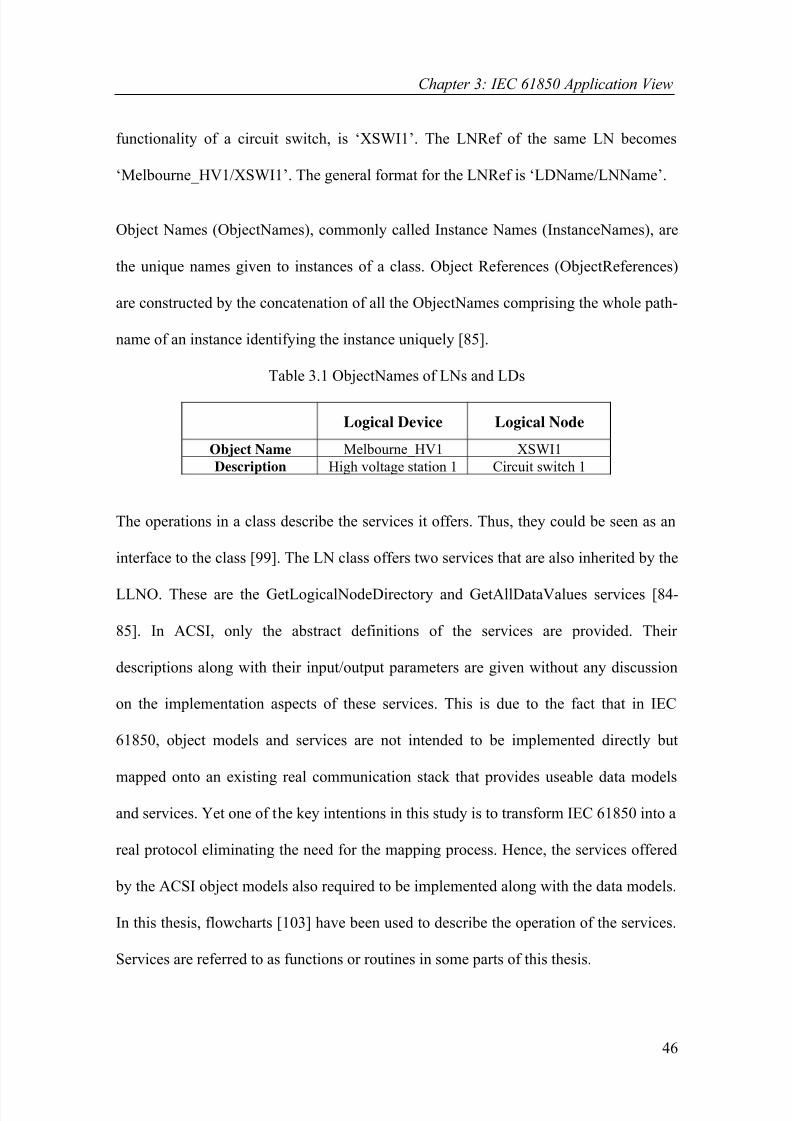
8/8/2019 02chapters1-4
http://slidepdf.com/reader/full/02chapters1-4 46/118
Chapter 3: IEC 61850 Application View
46
functionality of a circuit switch, is ‘XSWI1’. The LNRef of the same LN becomes
‘Melbourne_HV1/XSWI1’. The general format for the LNRef is ‘LDName/LNName’.
Object Names (ObjectNames), commonly called Instance Names (InstanceNames), are
the unique names given to instances of a class. Object References (ObjectReferences)
are constructed by the concatenation of all the ObjectNames comprising the whole path-
name of an instance identifying the instance uniquely [85].
Table 3.1 ObjectNames of LNs and LDs
Logical Device Logical Node
Object Name Melbourne_HV1 XSWI1
Description High voltage station 1 Circuit switch 1
The operations in a class describe the services it offers. Thus, they could be seen as an
interface to the class [99]. The LN class offers two services that are also inherited by the
LLNO. These are the GetLogicalNodeDirectory and GetAllDataValues services [84-
85]. In ACSI, only the abstract definitions of the services are provided. Their
descriptions along with their input/output parameters are given without any discussion
on the implementation aspects of these services. This is due to the fact that in IEC
61850, object models and services are not intended to be implemented directly but
mapped onto an existing real communication stack that provides useable data models
and services. Yet one of the key intentions in this study is to transform IEC 61850 into a
real protocol eliminating the need for the mapping process. Hence, the services offered
by the ACSI object models also required to be implemented along with the data models.
In this thesis, flowcharts [103] have been used to describe the operation of the services.
Services are referred to as functions or routines in some parts of this thesis.

8/8/2019 02chapters1-4
http://slidepdf.com/reader/full/02chapters1-4 47/118
Chapter 3: IEC 61850 Application View
47
3.3.1.2.1 GetLogicalNodeDirectory Service
Clients use this service to get the ObjectNames of all the instances contained within a
LN. The input/output parameters for this service are shown in Table 3.2 [85]. The
descriptions of input and output parameters of all services covered in this thesis are
provided in Appendix B.
Table 3.2 Parameters of the GetLogicalNodeDirectory service
Figure 3.7 shows the flowchart diagram of the GetLogicalNodeDirectory service. The
GetLogicalNodeDirectory service starts by declaring and initialising local variables
used throughout the program. If the LNReference parameter is not correctly assigned
with a string, the service exits with an appropriate service error message. Otherwise, it
moves on to search the LD list of the current server to locate the LD specified in the
LNReference. As described earlier, the LNReference consists of two parts: LNName
and LDName. The service runs through the LD list comparing each member’s name
with the LDName specified by the LNReference. If the end of the LD list is reached
without the target being located, the service exits with another appropriate service error
message. Otherwise, it advances to search the LN list of the recently located LD to find
the LN specified by the LNReference. Next, the ACSIClass input parameter is evaluated
to determine the ACSI class type for which ObjectNames need to be returned. The
ObjectNames of all the matching instances are copied to the InstanceName [0...n] return
parameter.
Input Parameters Output Parameters
(if operation successful)
Output Parameters
(if operation unsuccessful)LNReference InstanceName[0...n]
ACSIClass Response+Response-

8/8/2019 02chapters1-4
http://slidepdf.com/reader/full/02chapters1-4 48/118
Chapter 3: IEC 61850 Application View
48
START
Declare and initialize all variables
found = false, i = 0 , j =0
LNReference
== NULL
Response -(LNReference can
not be NULL)
END
While (found
== false)
If (The end of
Servers' s
LD list reached)
F
T
If(LDName of LD [i]
== LDName)
found = true
T
F
While (found
== false)
If(The end of LD' s
LN list reached)
F
T
If(LNName of LN [j]
== LNName)
found = true
T
F
T
F
If(ACSIClass ==
DATA)
InstanceName[0..n] =
DataNames[0..n]
If(ACSIClass ==
DATA_SET)
InstanceName[0..n] =
DataSetNames[0..n]
T T
F If(ACSIClass ==
...........)
InstanceName[0..n] =
........Names[0..n]
F
T
Split LNReference into two : LDName
and LNName
Response -
(LD can not be
found)
T
i ++
found = false
j ++
Response -
(LN can not be
found)
END
END
F
T
END
Response +(Service Request
Succeed)
F
If (A valid
ACSIClass
specification)
T
Response -
(ACSIClassincorrectly
specified)
F
Figure 3.7 Flowchart diagram of the GetLogicalNodeDirectory service

8/8/2019 02chapters1-4
http://slidepdf.com/reader/full/02chapters1-4 49/118
Chapter 3: IEC 61850 Application View
49
3.3.1.2.2 GetAllDataValues Service
Clients use this service to retrieve the data attribute values (DataAttributeValues) of all
data contained within a LN. Table 3.3 shows the input/output parameters for this service
[85]. Figure 3.8 shows the flowchart diagram of the GetAllDataValues service.
Table 3.3 Parameters of the GetAllDataValues of the service
END
If (An acceptableFC specified)
F
T
While (Not
the end LN Datalist)
move pointer to
Data[k]
While (Notthe end Data[k]'s
DataAttributelist)
DataAttributeReference [index] = ObjectReference of DataAttribute [z]DataAttributeValue [index] = Value of DataAttribute [z]index = index +1
z= z+1
T
T
k =k+1
F
Response + Service
Request Succeed
F
If (FC ofDataAttribute[z]== request FC)
T
F
Response -( FC incorrectly
specified)
Figure 3.8 Flowchart diagram of the GetAllDataValues service
Input Parameters Output Parameters(if operation successful)
Output Parameters(if operation unsuccessful)
LNReference LNReference
FunctionalConstraint [0..1] DataAttributeReference[1...n]Response-
DataAttributeValue [1...n]
Response+

8/8/2019 02chapters1-4
http://slidepdf.com/reader/full/02chapters1-4 50/118
Chapter 3: IEC 61850 Application View
50
The initial parts of the GetAllDataValues service, where the local variables are declared
and LNReference parameter is verified, are exactly the same as the previous service.
Hence, they have been excluded in the flowchart of Figure 3.8. Once the target LD and
LN are located, the service searches all DataAttributes within the data members of the
target LN and filters out the ones that have a Functional Constraint (FC) value matching
the value of the FC received in the request. ObjectReferences and values of the filtered
DataAttributes are copied to the return parameters.
3.3.2 Data
Data and LNs are the most important concepts used to describe real time system and
their functions. LNs are containers of data that represent meaningful and exchangeable
application specific information. Each LN builds up a specific functionality by grouping
several Data classes [84]. For example, the XCBR LN implements the functionality of a
circuit breaker by grouping a total number of sixteen Data classes as shown in Figure
3.9. IEC 61850-7-4 defines a total number of some 500 Data classes usually referred to
as Compatible Data Classes (CDCs).
XCBR
Mod Beh Health
CBOpCap
SumSwARa
ChMotEna
MaxOpCap
BlkOpen
Pos OpCnt
EENameEEHealth
Loc
NamPlt
POWCap BlkCls
Figure 3.9 Data Classes of the XCBR LN

8/8/2019 02chapters1-4
http://slidepdf.com/reader/full/02chapters1-4 51/118
Chapter 3: IEC 61850 Application View
51
In addition to representing application specific information, the data also builds the
basis of most information exchange over the network interacting with the environment
through services. This is depicted in Figure 3.10, which shows services that operate on
data. Some of the services shown in Figure 3.10 are the Data class assigned services
while others are the services of various other ACSI models that operate on data. Control
and substitution services fall into this category. A control service is used to group data
into data sets for reporting or logging purposes and a substitution service is used for
replacing values of DataAttributes contained in data. Get/Set and Dir/Definition are the
Data class assigned services used for reading/writing data values and retrieving
directory/definition information of a particular data instance [84-85].
Logical Node
Data SetData
Response Control
Response Get/Set
Response Substitution
Response Dir/Definition
Report
Log
Figure 3.10 Services operating on data
3.3.2.1 Modelling Data and Data Attributes
The Data class represents meaningful information of applications located in automation
devices. Figure 3.11 shows the conceptual class model of the Data class illustrating the
inheritance and relations between the Data class and its building blocks. The Data class
includes the DataName, DataRef and Presence attributes. The DataName attribute
defines the InstanceName of a data object whereas the DataRef attribute is the unique

8/8/2019 02chapters1-4
http://slidepdf.com/reader/full/02chapters1-4 52/118
Chapter 3: IEC 61850 Application View
52
path-name of a data object. The Boolean type Presence attribute states if the data object
is mandatory or optional. The Data class is also a composition of Simple Common Data
Classes (SimpleCDCs), Composite Common Data Classes (CompositeCDCs) and data
attributes (DataAttributes) as shown in Figure 3.11. Each data may be a composition of
zero or more instances of CompositeCDCs, SimpleCDCs or DataAttributes. However, it
must contain at least one of these elements [82, 85].
Figure 3.11 Data conceptual class model
The relationship between the Data and DataAttribute classes is the easiest to explain. A
composition aggregation exists between these simply indicating that each instance of
the Data class can be a composition of zero-to-many DataAttributes. Composition
aggregation is used in this case since in the absence of CompositeCDCs and
SimpleCDCs, the data object must have at least one DataAttribute.
The relationship between CompositeCDCs and the Data class is rather confusing. Each
CompositeCDC is a specialisation of the Data class indicated by the solid line with a
hollow triangle at the end. A specialisation is a relationship between the more general
element and a more specific element. In this case, the CompositeCDC happens to be the

8/8/2019 02chapters1-4
http://slidepdf.com/reader/full/02chapters1-4 53/118
Chapter 3: IEC 61850 Application View
53
more specific element that is fully consistent with the more general element (Data)
containing additional information. The structure of the Data class is recursive since
CompositeCDCs are also of type Data class. However, the number of levels of recursion
of CompositeCDCs is usually limited to 1. SimpleCDCs are of type CommonData,
which is a subclass of the Data class. This subclass relationship was once gain indicated
by the solid line with a hollow triangle connecting the SimpleCDC and Data classes.
The Data and CommonData class models can be defined as shown in Figures 3.12 and
3.13 respectively. Although the Data class diagram shows the possibility of including
zero-to-many CompositeCDCs, in practice this is limited to only 1 [85]. Part 7-3 lists a
total number of 29 CDCs [86]. Examples are: Single Point Status (SPS) and Measured
Value (MV).
tered Trial Version EA 5.0
tered Trial Version EA 5.0
tered Trial Version EA 5.0
tered Trial Version EA 5.0
DATA
+ DataName: CosNaming::NameComponent
+ DataRef: char [1..255 ] ([255])
+ Presence: bool
+ Data_att: DataAttribute*
+ CompositeCDC: DATA*
+ SimpleCDC: COMMON_DATA*
+ GetDataVal ues() : void**
+ SetDataVal ues() : void
+ GetDataDirectory() : void
+ GetDataDefinition() : void
Figure 3.12 Data class diagram
tered Trial Version EA 5.0
tered Trial Version EA 5.0
DATA
COMMON_DATA
+ DataName: CosNaming::NameComponent
+ DataRef: char [1..255] ([255])
+ Data_att: DataAttribute*
+ Presence: bool
Figure 3.13 CommonData class diagram

8/8/2019 02chapters1-4
http://slidepdf.com/reader/full/02chapters1-4 54/118
Chapter 3: IEC 61850 Application View
54
Figure 3.14 shows the conceptual model of the DataAttribute struct illustrating the
inheritance and relationships between the DataAttribute struct and its building blocks.
Each DataAttribute has a DataAttributeType, a Functional Constraint (FC) and zero-to-
many Trigger Options (TrgOps) as shown in Figure 3.14. DataAttributes are used for a
broad range of purposes; for example, for measurement indication, for controlling
purposes and for reporting. The FC is used to classify DataAttributes according to their
specific area of use. ACSI defines 18 FCs that can be used for this purpose. For
instance, “ST” is used for DataAttributes that represent status information whilst “MX”
is used for DataAttributes that represent measurement information. TrgOps, of type
TriggerConditions, are used to indicate the trigger conditions related to a DataAttribute
that may cause the transmission of a report or a new log entry into a log. There are 3
trigger conditions defined in ACSI for DataAttributes. They are the data-change (dchg);
quality-change (qchg) and data-value-update (dupd) trigger conditions [85].
A specific data type, the DAType, has been defined as the data type of the
DataAttributeType attribute. The DAType is also a class with a number of attributes.
Figure 3.14 also shows the detailed conceptual class diagram of the DAType class. The
DATName attribute identifies a DAType object within the scope of a DataAttribute
whereas the DATRef attribute is the pathname of the DAType object. The Boolean type
Presence attribute indicates whether the DataAttribute is compulsory or optional. As
demonstrated in the conceptual class diagram of Figure 3.14, the DAType class may
contain either a single Primitive Component (PrmCmp) or zero-to-many Composite
Components (CmpCmps). The structure of the DAType class is recursive as well since
CmpCmps are of type DAType. Therefore, DataAttributes can be nested, as shown in
Figure 3.15, with the number of levels of nesting being normally no greater than 3 [85].

8/8/2019 02chapters1-4
http://slidepdf.com/reader/full/02chapters1-4 55/118
Chapter 3: IEC 61850 Application View
55
Figure 3.14 DAType conceptual class model
DATA Instance
DataAttribute1 DataAttribute2
PrCmp
CmpCmp2CmpCmp1
PrCmp
CmpCmp2CmpCmp1
PrCmpPrCmp
Level 1
Level 2
Level 3
Figure 3.15 Nested DataAttributes
PrmCmps have primitive data types such as BOOLEAN, INT8, FLOAT32 or VISIBLE
STRING. On the contrary, CmpCmps have complex data types constructed from
primitive data types (BasicTypes). The structure of the complex data types can get
extremely compound due to the recursive property of the DAType class. As illustrated
in Figure 3.15, each CmpCmp can further be a composition of a number of CmpCmps
each having either a primitive type or a complex type (further nesting). However, the

8/8/2019 02chapters1-4
http://slidepdf.com/reader/full/02chapters1-4 56/118
Chapter 3: IEC 61850 Application View
56
number of levels of recursion of CmpCmps is generally no greater than 2. The identical
recursive property is also experienced when constructing Functionally Constraint Data
Attribute Types (FCDATypes). The DATypes of first level DataAttributes are often
called FCDATypes, which are created from primitive and complex data types as shown
in Figure 3.16. In ACSI, complex data types are defined either as Common ACSI Types
in Part 7-4 [87] or as Common Data Attribute Types in Part 7-3 [86].
Figure 3.16 FCDAType conceptual class model
Figure 3.17 depicts an excerpt of a data instance contained in the XCBR1. The XCBR1
LN instance (instantiated from XCBR) is composed of ‘Pos’, which is an instantiation
of the Controllable Double Point (DPC) CDC. The ‘Pos’ Data class is used to represent
switch status or position and contains the DataAttribute ‘q’. The DataAttribute ‘q’
includes information on the quality of the information received from the server. It
comprises the CompositeComponent ‘detail-qual’, a bit string containing quality
identifiers. ‘Overflow’ is one of these identifiers. The DataAttribute ‘q’ has the FC
value of “ST” (status) and the TrgOp value of “qchg” (quality change).

8/8/2019 02chapters1-4
http://slidepdf.com/reader/full/02chapters1-4 57/118
Chapter 3: IEC 61850 Application View
57
XCBR1
XCBR1.Pos.q.detail-qual BitString
XCBR1.Pos.q Quality [ST] [qchg]
XCBR1.Pos
XCBR1.Pos.q.detail-qual.overflow Bit
Compatible LN Class
Composite CommonData Class
CompositeComponent
CompositeComponent
PrimitiveComponent
XCBR
DPC
Basic TypeCommon DataAttribute type
Instances Classes/types
LN Instance
Compatible Data Class
DataAttribute
DataAttributeComponent
Figure 3.17 Example of a data instance
3.3.2.2 Implementing Data and Data Attributes
The C++ definitions of the DataAttribute struct and the DAType class model are
included in Appendix A. The FC type was implemented as an enumeration that contains
all of the 18 possible FC values. The TriggerConditions type was implemented as a
struct with all trigger conditions as its members. The C++ definitions of the Data and
CommonData class models can also be viewed in Appendix A. The Data class offers
four services that are also inherited by the CommonData class [85].
3.3.2.2.1 GetDataDirectory Service
Clients use this service to retrieve the DataAttributeNames of all DataAttributes
contained within the referenced data. Table 3.4 shows input/output parameters for this
service [85]. Figure 3.18 shows the flowchart diagram of the GetDataDirectory service
Table 3.4 Parameters of the GetDataDirectory service
Input Parameters Output Parameters
(if operation successful)
Output Parameters
(if operation unsuccessful)
DataAttributeName[0...n]DataReference
Response+Response-

8/8/2019 02chapters1-4
http://slidepdf.com/reader/full/02chapters1-4 58/118
Chapter 3: IEC 61850 Application View
58
Find target LD using LDNameand LN using LNName
Split DataReference into three strings : LDName,LNName and DataName
While (found== false)
If (The end of LN' sDataList reached)
F
T
If (TheDataName of Data [z]
== DataName)
found = true
T
T
F
END
F
While(The end of Data[z][0] 's DataAttributeList
not reached)
DataAttributeName[index] =DatName of the DataAttribute[k]
k++, index++
Response +
(Service RequestSucceed)
T
F
Response -(Data can not
be found)z++
While (The end of Data[z][0] SimpleCDCList not
reached)
T
F
While(The end of
SimpleCDC [m] 'sDataAttributeList not
reached)
DataAttributeName[index] =DatName of the DataAttribute[k]
k++, index++
T
F
m++
k = 1
Figure 3.18 Flowchart diagram of the GetDataDirectory service
The service splits the DataReference input parameter received in the request into three
strings: LDName, LNName and DataName. After the target LD and LN are located as
described in detail in the previous flowcharts, the program continues by searching the
target LN’s data list in order to find a matching data member. The DataNames of all
members are compared one by one with the desired DataName and if a match is found
before the end of LN’s data list is reached then the service jumps to the next stage. By
this stage, the pointed member will be: LD[i].LN[j].Data[z]

8/8/2019 02chapters1-4
http://slidepdf.com/reader/full/02chapters1-4 59/118
Chapter 3: IEC 61850 Application View
59
The Data [z] itself does not contain any DataAttributes or SimpleCDCs. All attributes
and SimpleCDCs are included within the CompositeCDC component of Data [z].
Considering this rule, the service jumps directly to the member: LD [i].LN [j].Data
[z].CompositeCDC [0], which will be referred to as Data [z] [0] in this thesis for
simplicity. The final stage includes two tasks. First the possibility of the presence of any
SimpleCDCs has to be considered, which is carried out by processing the Data [z] [0]’s
SimpleCDC list and copying the DatNames of all first level DataAttributes to the return
parameter. Similarly, the Data [z] [0]’s DataAttribute list is also processed and
DatNames of all first level DataAttributes are copied to the return parameter.
3.3.2.2.2 GetDataDefinition Service
Clients use this service to retrieve the definitions of all DataAttributes contained within
the referenced data. Table 3.5 shows the input/output parameters for this service [85].
Table 3.5 Parameters of the GetDataDefinition service
3.3.2.2.3 GetDataValues Service
Clients use this service to retrieve the values of DataAttributes contained within the
referenced data. Table 3.6 shows the output parameters for this service [85]. Figures
3.19 and 3.20 show the flowchart diagrams of the GetDataValues service.
Table 3.6 Parameters of the GetDataValues service
Input Parameters Output Parameters(if operation successful)
Output Parameters(if operation unsuccessful)
DataAttributeDefinition[0...n]DataReference
Response+Response-
Input Parameters Output Parameters(if operation successful)
Output Parameters(if operation unsuccessful)
DataAttributeValue[1...n]FCDA
Response+Response-

8/8/2019 02chapters1-4
http://slidepdf.com/reader/full/02chapters1-4 60/118
Chapter 3: IEC 61850 Application View
60
START
Declare andinitialize all variables
FCDA== NULL
Response -( FCDA
can not beNULL)
Find target LD, LN ,and Data
Seperate FCDA into 8 strings : FC, LDName,LNName, DataName,SimpleCDCName
DataAttributeName, CompositeDataAttributeName,CompositeCompositeDataAttributeName
While (The end ofData[z][0]'s
DataAttributeList notreached)
if (DatName ofDataAttribute [k] ==DataAttributeName)
found = true
Response -(DataAttribute can
not be found)
if (DataAttributeCompositeName
== NULL)
k ++
DataAttributeValue[0] = Value of theDataAttribute[k]
Response -(FC incorrectly
Specified)if (FC of
DataAttribute [k] ==Target FC
While (The end ofDataAttribute[k]'s
CompositeDataAttributeList
not reached)
l ++
if (DAComponentName ofComposite DataAttribute [l] ==CompositeDataAttributeName)
found = true
if (CompositeCompositeDataAttribute
Name == NULL)
DataAttributeValue
[0] = Value of theCompositeDataAttribute[l]
Response -(FC incorrectly
Specified)
if (FC ofComposite
DataAttribute [l] ==Target FC
While (The end of CompositeDataAttribute[l]'s Composite
DataAttributeList not reached)
m ++
if (DAComponentName ofCompositeComposite DataAttribute
[m] == CompositeCompositeDataAttributeName)
found = true
if (FC ofCompositeCompositeDataAttribute [m] ==
Target FC
DataAttributeValue[0] = Value of the
CompositeComposite DataAttribute[m]
Response -(FC incorrectly
specified)
Y
Y
Y
Y
Y
Y
Y
Y
Y
Y
Y
Response -(Composite
DataAttribute cannot be found)
N
N
N
N
N
N
N
N
N
N
N
Response -(CompositeCompositeDataAttributecan not befound)
N
While (The end ofData[z][0]'s
SimpleCDCList notreached)
if (DataName ofSimpleCDC [p] ==SimpleCDCName)
p ++
Y
N
SimpleCDCfound= true
Y
SECOND
FLOWCHART
N
Y
Figure 3.19 Flowchart diagram of the GetDataValues service

8/8/2019 02chapters1-4
http://slidepdf.com/reader/full/02chapters1-4 61/118
Chapter 3: IEC 61850 Application View
61
Once the target LD, LN and data are located, the target Data [z] [0]’s SimpleCDC list is
processed comparing the DataName of every member to the desired SimpleCDCName.
If a match is not found, the service moves on to locate a matching DataAttribute [k] in
the Data [z] [0]’s DataAttribute list. If a matching DataAttribute [k] is found, the service
determines whether a first, second, or third level data attribute is searched for by
validating the values of the CompositeDataAttributeName (CDAN) and
CompositeCompositeDataAttributeName (CCDAN).
While (The end ofSimpleCDC[p]'s
DataAttributeList notreached)
if (DatName ofDataAttribute [k] ==DataAttributeName)
found = true
Response -(DataAttribute can
not be found)
if (DataAttributeCompositeName
== NULL)
k ++
DataAttributeValue[0] = Value of theDataAttribute[k]
Response -(FC Incorrectly
Specified)
if (FC ofDataAttribute [k] ==
Target FC
While (The end ofDataAttribute[k]'s
CompositeDataAttributeList
not reached)
if (FC ofCompositeCompositeDataAttribute [m] ==
Target FC
DataAttributeValue[0] = Value of the
CompositeComposite DataAttribute[m]
Response -(FC incorrectly
Specified)
Y
Y
Y
Y
Y
Response -(Composite
DataAttribute cannot be found)
N
N
N
N
N
N
Y
l ++
found = true
if (CompositeCompositeDataAttribute
Name == NULL)
DataAttributeValue[0] = Value of the
CompositeDataAttribute[l]
Response -(FC incorrectlySpecified)
if (FC ofComposite
DataAttribute [l] ==Target FC
While (The end of CompositeDataAttribute[l]'s Composite
DataAttributeList not reached)
m ++
if (DAComponentName ofCompositeComposite DataAttribute
[m] == CompositeCompositeDataAttributeName)
found = true
Y
Y
Y
Y
Y
N
N
N
N
Response -(CompositeCompositeDataAttributecan not befound)
if (DAComponentName ofComposite DataAttribute [l] ==CompositeDataAttributeName)
N
Figure 3.20 Continued flowchart diagram of the GetDataValues service

8/8/2019 02chapters1-4
http://slidepdf.com/reader/full/02chapters1-4 62/118
Chapter 3: IEC 61850 Application View
62
After the service determines how many levels to advance, it progresses that many levels
and locates the DataAttribute comparing its FC value with the value of the FC specified
in the FCDA. If they are the same, it copies the value of the DataAttribute to the return
parameter. The program of GetDataValues service steps into the code illustrated by the
flowchart of Figure 3.20 only if a matching SimpleCDC [p] entry was found earlier.
3.3.2.2.4 SetDataValues Service
Clients use this service to set the values of the DataAttributes contained within the
referenced data. Table 3.7 shows the input/output parameters for this service [85].
Table 3.7 Parameters of the SetDataValues service
This service involves setting the value of the DataAttribute specified in the FCDA
making use of the value of the input parameter (DataAttributeValue [0]). Such as:
Value of DataAttribute [k] = DataAttributeValue [0]
Value of CompositeDataAttribute [l] = DataAttributeValue [0]
Value of CompositeCompositeDataAttribute [m] = DataAttributeValue [0]
3.3.3 Data Sets
The DataSet class model is used to initiate data set (DataSet) objects that hold the
ObjectReferences of DataAttributes in an organised manner as shown in Figure 3.21.
The use of DataSets brings ease to the client as the current values of data and
DataAttributes referenced in each DataSet can be retrieved without difficulty as long as
Input Parameters Output Parameters(if operation successful)
Output Parameters(if operation unsuccessful)
FCDA
DataAttributeValue[1...n]Response+ Response-

8/8/2019 02chapters1-4
http://slidepdf.com/reader/full/02chapters1-4 63/118
Chapter 3: IEC 61850 Application View
63
membership and order of ObjectReferences is known both to the client and the server.
Besides being as a safe and quick means of retrieving data and DataAttribute values,
DataSets are also used by the control models such as reporting and logging [84 -85].
Figure 3.21 DataSet members
3.3.3.1 Modelling and Implementing Data Sets
Figure 3.22 shows the DataSet class diagram, which is based on the DataSet class
definition provided in Part 7-2. Unlike the Object Models (OM) described earlier,
DataSets contain only simple attributes. The DSName attribute identifies a DataSet
within the scope of a LN while the DSRef attribute represents the unique path-name of
the DataSet object. The attribute DSMemberRef holds the ordered ObjectReferences of
data and DataAttributes. The C++ definition of the DataSet class model is included in
Appendix A as well. Other than the attributes, the DataSet class model supports five
services that can be used by the clients to perform DataSet related operations.
Figure 3.22 DataSet class diagram
DataSet
LDName/XCBR1.Pos.ctlValLDName/XCBR1.Pos.stlValLDName/XCBR1.Pos.q
LDName/XCBR1.Pos.operTimLDName/XCBR1.Pos.t……………….
cd Use Case View
EA 5.0 Unregistered Trial Version EA 5.0 Unregistered Trial Version
EA 5.0 Unregistered Trial Version EA 5.0 Unregistered Trial Version
EA 5.0 Unregistered Trial Version EA 5.0 Unregistered Trial Version
EA 5.0 Unregistered Trial Version EA 5.0 Unregistered Trial Version
EA 5.0 Unregistered Trial Version EA 5.0 Unregistered Trial Version
EA 5.0 Unregistered Trial Version EA 5.0 Unregistered Trial Version
EA 5.0 Unregistered Trial Version EA 5.0 Unregistered Trial Version
EA 5.0 Unregistered Trial Version EA 5.0 Unregistered Trial Version
EA 5.0 Unregistered Trial Version EA 5.0 Unregistered Trial Version
EA 5.0 Unregistered Trial Version EA 5.0 Unregistered Trial Version
EA 5.0 Unregistered Trial Version EA 5.0 Unregistered Trial Version
DATA_SET
+ DSName: CosNaming::NameComponent
+ DSRef: char [1..255] ([255])
+ DSMemberRef: char**
+ CreateDataSet(char*, char**, char**, char**) : void
+ DeleteDataSet(char*, char**, char**) : void
+ GetDataSetDirectory(char*, char**, char**, char**) : void
+ SetDataSetValues(char*, void**, char**, char**) : void
+ GetDataSetVal ues(char*, void**, char**, char**) : void

8/8/2019 02chapters1-4
http://slidepdf.com/reader/full/02chapters1-4 64/118
Chapter 3: IEC 61850 Application View
64
3.3.3.1.1 CreateDataSet Service
Clients can use this service to request servers to create DataSets or configure DataSets.
The input/output parameters for this service are shown in Table 3.8 [85]. Figure 3.23
shows the flowchart diagram of the CreateDataSet service.
Table 3.8 Parameters of the CreateDataSet service
END
T
T
F
T
F
Any DataSets previouslycreated for
this LN
create a newDataSet for this
LN
While(found1 == false )
if (DSRef of DataSet[k]== DataSetReference )
found1 = true
DSMemberRef of DataSet [k] = DSMemRef
DSName of DataSet[k] = DataSetNameDSRef of DataSet[k] = DataSetReferenceDSMemberRef of DataSet[k] = DSMemRef
k ++ if (The end of this LN'sDataSetList reached)
T
F
Response +(DSMemberReference
has been updated)
Response +
(A new DataSetcreated)
Figure 3.23 Flowchart diagram of the CreateDataSet service
If DataSets have not been previously created for the current LN, then a new DataSet
with the index of “zero” is created and its attributes are set. Otherwise, the DataSet is
created with the smallest available index.
Input Parameters Output Parameters
(if operation successful)
Output Parameters
(if operation unsuccessful)
DataSetReference
DSMemRef [1…n] Response+ Response-

8/8/2019 02chapters1-4
http://slidepdf.com/reader/full/02chapters1-4 65/118
Chapter 3: IEC 61850 Application View
65
3.3.3.1.2 DeleteDataSet Service
Clients can use this service to request servers to delete a DataSet. The input/output
parameters for this service are shown in Table 3.9 [85]. Figure 3.24 shows the flowchart
diagram of the DeleteDataSet service.
Table 3.9 Parameters of the DeleteDataSet service
END
T
F
if (The end of this LN 's
DataSetList reached)
if (DSRef of DataSet[k]== DataSetReference )
k ++
Response -
(DataSet can not befound)
F
found = truebreak
TWhile (The end of
this LN's DataSetList notreached)
DataSet[k] = DataSet[k+1]
Response +(Service Request
Succeed)
T
While (found == false)
k ++
F
T
Figure 3.24 Flowchart diagram of the DeleteDataSet service
3.3.3.1.3 SetDataSetValues Service
Clients can use this service to set the values of all referenced DataAttributes contained
within the DataSet. Table 3.10 shows the input/output parameters for this service [85].
Table 3.10 Parameters of the SetDataSetValues service
Input Parameters Output Parameters
(if operation successful)
Output Parameters
(if operation unsuccessful)
DataSetReference Response+ Response-
Input Parameters Output Parameters(if operation successful)
Output Parameters(if operation unsuccessful)
DataSetReference
DataAttributeValue [1…n]Response+ Response-

8/8/2019 02chapters1-4
http://slidepdf.com/reader/full/02chapters1-4 66/118
Chapter 3: IEC 61850 Application View
66
Figure 3.25 shows the flowchart diagram of the SetDataSetValues service. After the
DataSet [k] referenced by the DataSetReference is located, the service copies current
values of all the DataAttributes referenced by the DSMemberRef attribute of the
DataSet [k] to a dummy variable (OldDataValues [1...n]) for later use in the control
blocks. After this is accomplished, the service changes the values of all DataAttributes
to the new values contained within the DataAttributeValue [1...n] input parameter.
found = truebreak
T
F
z ++
while (The end of DataSet[k] ' sDSMemberList not reached )
T
OldDataValues [z] = Value of the DataAttributereferenced by DSMemberRef [z]
z ++
while (The end of DataSet[k] ' sDSMemberList not reached )
T
Value of the DataAttribute referenced byDSMemberRef [z] = DataAttributeValue[z]
z = 0
F
Figure 3.25 Flowchart diagram of the SetDataSetValues service
3.3.3.1.4 GetDataSetValues Service
Clients can use this service to get the values of all DataAttributes contained within the
referenced DataSet. Table 3.11 shows the input/output parameters for this service [85].
Table 3.11 Parameters of the GetDataSetValues service
The flowchart diagram of the GetDataSetValues service is similar to the flowchart
diagram shown in Figure 3.25 except that in the final stage, the values of the
DataAttributes referenced by the DSMemberRef [1...n] attribute of the DataSet are
copied to the return parameter (DataAttributeValue [1...n]).
Input Parameters Output Parameters(if operation successful)
Output Parameters(if operation unsuccessful)
DataAttributeValue [1…n]DataSetReference
Response+Response-

8/8/2019 02chapters1-4
http://slidepdf.com/reader/full/02chapters1-4 67/118
Chapter 3: IEC 61850 Application View
67
3.3.3.1.5 GetDataSetDirectory Service
Clients can use this service to retrieve the list of the ObjectReferences of all data and
DataAttributes referenced by the DSMemberRef [1...n] attribute of the referenced
DataSet. The input/output parameters for this service are shown in Table 3.12 [85].
Table 3.12 Parameters of the GetDataSetDirectory service
3.3.4 Reporting and logging
The internal events called DataObjects, grouped by DataSets as shown in Figure 3.26,
form the basis for reporting and logging.
controls
DO
DO
DO
DO
DO
DO
DO
DO
DO
Data change
& update
Quality changeevents
DataObjects in a
DataSet
Event
Monitor
ReportingReport Control
Report Handler
Filter & Formatting
controls
Buffered Re ort
Un uff. Report
Get/Set
Request
Get/Set
Response
Logging
controls
Get/Set
Request
Get/Set
Response
Log Control
Log Handler
Filter & Formatting
Log
Query Request
Query Response
Buffer
Figure 3.26 Reporting and logging model
Input Parameters Output Parameters
(if operation successful)
Output Parameters
(if operation unsuccessful)
DSMemRef [1...n]
DataSetReference Response+ Response-

8/8/2019 02chapters1-4
http://slidepdf.com/reader/full/02chapters1-4 68/118
Chapter 3: IEC 61850 Application View
68
Logging makes it possible to store data for future enquiries. Logs are used to store data
values in the form of log entries.The logging model is composed of four building
blocks, which are the: event monitor, log handler, log control and log. The event
monitor checks the values and state of the DataAttributes and data referenced within a
specified DataSet and determines the time when to inform the log handler of the
occurrence of an internal event. A filtering mechanism within the log handler is used to
reduce the amount of data to be stored in a log based on pre-configured conditions. The
log handler carries out the task of formatting data values as log entries storing them into
the log. Finally, the log control block is used to set/get log control attributes, which
control the operation of the log handler and event monitor [84-85].
Reporting enables a LN to transfer values of data to a client either immediately or after
some buffer time. The operation of the reporting model is quite similar to the one of the
logging model. The report control block is used to set or read the attribute values that
control the operation of the event monitor and report handler. Event monitor observes
the values and state of the DataAttributes and data informing the report handler when
changes occur. The report handler formats the data values into a report structure and
decides when to forward the report to the subscribed client. The report may be
transferred immediately or after being buffered for a while. Similarly, a filtering
mechanism within the report handler reduces the amount of data to be reported [84-85].
3.3.4.1 Reporting
The principle condition for report generation is the changes or updates in the values of
the member DataAttributes of a particular DataSet. Three types of changes, which are
also referred to as attribute TrgOps, can be expected. They are the:

8/8/2019 02chapters1-4
http://slidepdf.com/reader/full/02chapters1-4 69/118
Chapter 3: IEC 61850 Application View
69
(1) Data-change: a change in a value of a DataAttribute representing process-related
data is referred to as data-change. The data-change trigger option (TrgOp =
dchg) signifies such a change.
(2) Quality-change: a change in a quality value of a DataAttribute is called quality-
change (TrgOp= qchg).
(3) Data-update: a freeze event in a value of a DataAttribute is called data-update
(TrgOp= dupd). A change or update in a value of a DataAttribute with the same
value as before represents a freeze event.
As indicated in the previous section, a report control block is used for controlling the
procedures necessary to transmit values of data and DataAttributes from a LN to a
client. In Part 7-2, two types of report control blocks are defined. These are the:
(1) Buffered Report Control Block (BRCB) – changes in the values of DataAttributes
and data caused by trigger options data-change, quality-change and data-update issue
immediate or buffered transmission of values. Buffering is useful when there is a loss of
connection or the transport data flow is not fast enough to support the immediate
transmission. The transmission of the values can be delayed to some practical limit by
buffering and the report can be sent soon after the transmission media becomes
available. Thus, the likelihood of values getting lost is fairly low [85].
(2) Unbuffered Report Control Block (URCB) – changes in the values of DataAttributes
and data caused by trigger options data-change, quality-change and data-update can
only issue immediate transmission of values. The values may get lost if the transmission
media cannot meet the transmission needs of the immediate transfer. The key advantage
concerned with the URCB is that values are transmitted on a “best effort” service soon

8/8/2019 02chapters1-4
http://slidepdf.com/reader/full/02chapters1-4 70/118
Chapter 3: IEC 61850 Application View
70
after the event occurs without any delay [85]. It is hard to justify the need for URCB
since an instance of a BRCB can simply be configured to perform the task of an URCB
that is to issue immediate transmission of values. For this reason, in this study, only the
BRCB class has been explored in detail.
3.3.4.1.1 Modelling and Implementing the Buffered Report Control Block
The BRCB class model is shown in Figure 3.27 [85]. Other than the attributes, the
BRCB class model supports three services that can be used by the clients to perform
BRCB related operations. The C++ definition of the BRCB class model can be found in
Appendix A.
n EA 5.0 Unregistered Trial
n EA 5.0 Unregistered Trial
n EA 5.0 Unregistered Trial
n EA 5.0 Unregistered Trial
n EA 5.0 Unregistered Trial
n EA 5.0 Unregistered Trial
BRCB_Class
+ BRCBName: CosNaming::NameComponent
+ BRCBRef: char [1..255] ([255])
+ RptID: char [1..65] ([65])
+ RptEna: bool
+ DatSet: char [1..255] ([255])+ ConfRev: unsigned _in t32
+ OptFlds: PACKET_LIST_BOOLEAN
+ BufTm: unsigned _int32
+ SqNum: unsigned _int64
+ TrgOp: TriggerConditions
+ IntgPd: unsigned _int32
+ PurgeBuf: bool
+ EntryID: bool
+ Tim eOfEntry: Time_Stamp
+ GI: Tim e_Stamp
+ SetBRCBValues() : void
+ GetBRCBValues() : void
+ Report() : void
Figure 3.27 BRCB class diagram
3.3.4.1.1.1 SetBRCBValues Service
Clients can use this service to request servers to create BRCBs or configure BRCB
attribute values. Table 3.13 shows the input/output parameters for this service [85].

8/8/2019 02chapters1-4
http://slidepdf.com/reader/full/02chapters1-4 71/118
Chapter 3: IEC 61850 Application View
71
Table 3.13 Parameters of the SetBRCBValues service
Figure 3.28 shows the flowchart diagram of the SetBRCBValues service.
END
If (BRCBRef of BRCB[k] ==BRCBReference )
k ++
F
found = true
T
If (ReportIdentifier == "NULL" )
ReportIdentifier = BRCBRef of BRCB[k]
Set all the attributevalues of the
BRCB accordingto the inputparameters
Response +(SetBRCBValuesService Request
Succeed)
if (The end of this LN'sBRCBList reached)
F
T
F
If (ReportIdentifier == "NULL" )
ReportIdentifier = BRCBReference
Create a new BRCB for this LNand then set all the attribute
values of the BRCB accordingto the input parameters
T
F
T
Response +
(A new BRCB created)
Figure 3.28 Flowchart diagram of the SetBRCBValues service
Input Parameters Output Parameters
(if operation successful)
Output Parameters
(if operation unsuccessful)BRCBReference Response+ Response-
FunctionalConstraint
ReportIdentifier
ReportEnable
DataSetReference
OptionalFields
BufferTime
TriggerConditionsEnabled
IntegrityPeriod
GeneralInterrogation
PurgeBuffer
EntryIdentifier

8/8/2019 02chapters1-4
http://slidepdf.com/reader/full/02chapters1-4 72/118
Chapter 3: IEC 61850 Application View
72
SetBRCBValues service is quite similar to the previously described CreateDataSet
service. Once the target LD and LN are located, the program searches the current LN’s
BRCB list to determine whether a BRCB with the given BRCBReference has
previously been created or not. If created before, its attributes are updated. Otherwise, it
will first be created and then its attributes will be set according to the input parameters.
In both cases, if a valid ReportIdentifier is not specified, it is set as the BRCBReference.
3.3.4.1.1.2 GetBRCBValues Service
Clients can use this service to retrieve the attribute values of the referenced BRCB. The
input/output parameters for this service are shown in Table 3.14 [85].
Table 3.14 Parameters of the GetBRCBValues service
3.3.4.1.1.3 Report Service
The report service is used for sending the reports generated by the BRCBs to clients. In
this project, the report service uses the mechanisms provided by the data delivery
network middleware (discussed subsequently in Chapter 5) to accomplish this task. As
soon as a report is generated, it will be forwarded to the appropriate client. Reports have
the format shown in Figure 3.29.
Input Parameters Output Parameters(if operation successful)
Output Parameters(if operation unsuccessful)
BRCBReference ReportIdentifier Response-
FunctionalConstraint ReportEnable
DataSetReference
ConfigurationRevision
OptionalFields
BufferTime
SequenceNumber
TriggerConditionsEnabled
IntegrityPeriod
EntryIdentifier
Response+

8/8/2019 02chapters1-4
http://slidepdf.com/reader/full/02chapters1-4 73/118

8/8/2019 02chapters1-4
http://slidepdf.com/reader/full/02chapters1-4 74/118
Chapter 3: IEC 61850 Application View
74
the same condition. In some cases, long reports not fitting into a single message
are divided into sub-reports sent individually. In such cases, the SubSeqNum
field is used to denote the segment number of each sub-report. The
MoreSegmentsFollow field is also related to this situation. When set to TRUE, it
indicates that more report segments (sub-reports) should be expected,
c) If the dat-set-name sub-attribute is set to TRUE, then the name of the DataSet
being monitored by the BRCB also needs to be included within the report,
d) The inclusion of the BufOvfl and ConfRev fields depend on the buffer-overflow
and conf-revision conditions as shown in Figure 3.32. BufOvfl, when set to
TRUE, indicates that a buffer overflow has occurred. ConfRev is derived from
the respective attribute of the BRCB, and
e) The most important field of the report is undoubtedly the Entry field, which
consists of the real data (EntryData [1...n]) to be sent to the client. If the report-
time-stamp and entryID sub-attributes are both set to TRUE, the TimeofEntry
and EntryID fields, copied from their respective attributes in the BRCB, are
included at the beginning of the Entry field. Each EntryData contains the
DataRef and Value of a specific member of the DataSet accompanied by the
ReasonCode set according to the TrgOp that caused the internal event.
Conditions do exist for the inclusion of the DataRef and ReasonCode fields.
3.3.4.1.2 Procedures for report generation
In this section, implementation issues related to event monitoring and report handling
are covered. The values and state of DataAttributes and data need to be continuously
observed by the event monitor, which informs the report handler when changes occur.

8/8/2019 02chapters1-4
http://slidepdf.com/reader/full/02chapters1-4 75/118
Chapter 3: IEC 61850 Application View
75
The report handler, on the other hand, is in charge of creating and forwarding reports
immediately or after some buffer time based on the BRCB’s BufTm setting. ACSI
solely describes principles related to event monitoring and report handling. However, no
concrete services have been defined or documented for these principles. In this project,
the intention is to define and develop such services.
3.3.4.1.2.1 Event_Monitor_Reporting Service
As illustrated in Figure 3.30, in case of a change produced by the DataAttribute ‘q’ of
the data ‘MyLD/XCBR.Pos.q’, this change will be detected by the event monitor and
reported to the report handler. The value for this member will be included in the report
only if the BRCB’s TrgOp attribute has been enabled and set to qchg.
MyLD/LLNO.TestRpt1-MyLD/XCBR.Pos.stVal[dchg]
-MyLD/XCBR.Pos.q[qchg]-MyLD/XCBR.Pos.t[dupd]
DataSet member to bereported
q changed producesinternal event
ReportDataSetReference = MyLD/LLNO.TestRpt1
MyLD/XCBR1.Pos.q
3 individual DataSetmembers
Figure 3.30 DataSet members and reporting
It is the task of the event monitor building block of the reporting model to detect such
changes in the values of member DataAttributes of a DataSet. A C++ routine was
designed and implemented in this study in order to model the tasks of the event monitor.
The flowchart representation of this routine is shown in Figure 3.31.

8/8/2019 02chapters1-4
http://slidepdf.com/reader/full/02chapters1-4 76/118
Chapter 3: IEC 61850 Application View
76
START
Declare and initialise variablesDataSetReference = DataSetReference from the input argument
OldValues= Values of DataAttributes from the input argument
Obtain the new DataAttribute values using the GetDataSetValuesservice
GetDataSetValues(DataSetReference, NewValues)
Call the Report_Handler service passing the set of new values andold values
Report_Hadler(DataSetReference, OldValues,NewValues)
Pause for 10us
Create the thread passing the DataSetReference and NewValues tothe thread
_ beginthread (Event_Monitor, (void*) dummy)
The new thread executesthe Event_Monitor service
passing theDataSetReference and
NewValues to the service
Figure 3.31 Event_Monitor_Reporting service
Once a BRCB is created and its attribute values are set using the SetBRCBValues
service, the Event_Monitor_Reporting service is called internally. The ObjectReference
of the DataSet monitored by this BRCB and the current values of its member
DataAttributes are passed to the Event_Monitor_Reporting service as input parameters.
The Event_Monitor_Reporting service makes use of the ObjectReference of the DataSet
to periodically acquire the values of all referenced DataAttributes within the DataSet.
When a new set of values is obtained, they are passed to the report handler together with
the older values from the previous run. Therefore, the Event_Monitor_Reporting service
periodically calls the report handler with the new and old set of DataAttribute values.
The periodic run is achieved with the use of Multi-Threading. Visual C++ provides the
Microsoft Foundation Class Library (MFC) to support for the multi-threaded
applications. A “thread” is a path of execution within a process. The
Event_Monitor_Reporting service uses the “_beginthread” function to create a thread
that begins the execution of the routine at periodic intervals of 100 ms.

8/8/2019 02chapters1-4
http://slidepdf.com/reader/full/02chapters1-4 77/118
Chapter 3: IEC 61850 Application View
77
3.3.4.1.2.2 Report_Handler Service
The task of the report handler is filtering the data received from the event monitor
formatting it into a report structure for transmission. In the example depicted in Figure
3.30, the value for the MyLD/XCBR.Pos.q will go through the filter only if the BRCB’s
TrgOp attribute is set to dchg. The flowchart for this service is shown in Figure 3.32.
T
F
While (found == false)
If (DatSet of BRCB[p]==DataSetReference )
p ++
F
found = true
T
If (The end of LN ' sBRCB reached )
T
Get all the BRCBattribute values
While (m < index)
If (olddata ==newdata)
z++m++
T
If (TrgOp of theDataAttribute == TrgOp
of the BRCB)
F
EntryData[l].DataRef =DSMemberReference of the DataAttribute
EntryData[l].DataRef = Value of theDataAttribute
l++
T
F
If (ReportEnable== true)
m++
T
F
If (BufTm ==0)
Add new entry tothe report
send the report
else if (BufTm > 0)
Response -(Report can not be set)
BRCB not enabled
T
F
F
Add new entry tothe report
If (TimerTime >BufTm)
Send the report
T
Response -(BufTm not set)
T
F
T
Figure 3.32 Report_Handler service

8/8/2019 02chapters1-4
http://slidepdf.com/reader/full/02chapters1-4 78/118
Chapter 3: IEC 61850 Application View
78
The Report_Handler service searches the BRCB list of the located LN until a matching
entry is found. After this is accomplished, all attribute values of the located BRCB [p]
are acquired with the use of the GetBRCBValues service.
The most critical stage is the subsequent stage where the old and new values reported by
the event monitor are compared. For each set of inconsistent values, the new values and
DSMemberReferences of the DataAttributes are copied to the appropriate sub-fields of
the EntryData header field of a report structure. If the ReportEnable attribute of the
BRCB is set to TRUE and the BufTm attribute is set as zero, the remaining fields of the
report structure will be formatted before the report is sent with the use of the Report ( )
service. In cases where the specified BufTm attribute is a non-zero value, the EntryData
header field is updated with the new values despite the fact that the report is not sent
immediately. If this is the first internal event, an internal timer is started for the duration
of the BufTm. For all subsequent events, the condition of the timer gets checked. As
soon as the timer expires (timer time equals to BufTm), the report gets sent. The timer is
restarted as soon as a new internal event occurs. If the PurgeBuf attribute is set to TRUE
at any point in time, all the previously buffered events will be discarded.
3.3.4.2 Logging
A log control block is used for controlling the procedures necessary to store values of
data and DataAttributes in a log as log entries that can be enquired at any time by
clients. Unlike reporting, which does not use any media for storage; logging makes use
of a log, a circular buffer, to store events for later retrieval. Event monitor, log handler,
log control and log are the main building blocks of the logging model as previously
indicated in Section (3.3.4). Class models have been defined in Part 7-2 for only the log

8/8/2019 02chapters1-4
http://slidepdf.com/reader/full/02chapters1-4 79/118
Chapter 3: IEC 61850 Application View
79
control and log building blocks [84-85]. Although the tasks of the remaining two are
clearly outlined in Part 7-2, no specific models have been put forward for those building
blocks. This subsection focuses on the two class models and additional services
designed and implemented to perform the tasks of event monitoring and log handling.
3.3.4.2.1 Modelling and Implementing the Log Control Block
The Log-Control-Block (LCB) class model, a template for the creation of LCB
instances, is shown in Figure 3.33. Each LCB associates a DataSet with a Log where
changes in values of members of the DataSet are stored as Log entries [85]. The C++
class definition of the LCB class is presented in Appendix A. In addition to the
attributes, the LCB class model supports two services that can be used by clients to
perform LCB related operations. These are the GetLCBValues and SetLCBValues
services, which are described in the following sections.
.
ion EA 5.0 Unregistered Tri
ion EA 5.0 Unregistered Tri
ion EA 5.0 Unregistered Tri
ion EA 5.0 Unregistered Tri
LCB_Class
+ LCBName: CosNaming::NameComponent
+ LCBRef: char [1..255] ([255])
+ LogEna: bool
+ DatSet: char [1..255] ([255])
+ OptFlds: PACKET_LIST_BOOLEAN
+ TrgOp: TriggerConditions
+ IntgPd: unsigned _int32
+ LogRef: char [1..255] ([255])
+ SetLCBValues() : void
+ GetLCBValues() : void
Figure 3.33 LCB class diagram
3.3.4.2.1.1 SetLCBValues Service
Clients use this service to request servers to create LCBs and configure their attribute
values. The input/output parameters for this service are shown in Table 3.15 [85].

8/8/2019 02chapters1-4
http://slidepdf.com/reader/full/02chapters1-4 80/118
Chapter 3: IEC 61850 Application View
80
Table 3.15 Parameters of the SetLCBValues service
3.3.4.2.1.2 GetLCBValues Service
Clients use this service to retrieve the attribute values of the referenced LCB. The
input/output parameters for this service are shown in Table 3.16. The GetLCBValues
service is identical to the GetBRCBValues service in methodology.
Table 3.16 Parameters of the GetLCBValues service
3.3.4.2.2 Modelling and Implementing the Log
The log is filled on a First-In First-Out (FIFO) basis. Although LCBs can reside within
any LN, the log itself must reside within the LLNO. Each LLNO is allowed only a
single log that can be controlled and used by multiple LCBs for data storage [84-85].
The Log class diagram is illustrated in Figure 3.34. The C++ definition of the Log class
can also be viewed in Appendix A.
Input Parameters Output Parameters
(if operation successful)
Output Parameters
(if operation unsuccessful)LCBReference Response+ Response-
FunctionalConstraint
LogEnable
DataSetReference
OptionalFields
IntegrityPeriod
LogReference
Input Parameters Output Parameters
(if operation successful)
Output Parameters
(if operation unsuccessful)
LCBReference Response+ Response-
FunctionalConstraint LogEnable
DataSetReference
OptionalFields
IntegrityPeriod
LogReference

8/8/2019 02chapters1-4
http://slidepdf.com/reader/full/02chapters1-4 81/118
Chapter 3: IEC 61850 Application View
81
ion EA 5.0 Unregistered Tr
ion EA 5.0 Unregistered Tr
ion EA 5.0 Unregistered Tr
ion EA 5.0 Unregistered Tr
LOG_Class
+ LogName: CosNaming::NameComponent
+ LogRef: char [1..255] ([255])
+ OldEntryTm: Tim e_Stamp+ NewEntryTm: Tim e_Stamp
+ OldEn try: unsigned _int32
+ NewEntry: unsigned _int32
+ Entry: entry*
+ QueryLogByTime() : void
+ QueryLogAfter() : void
+ GetLogStatusValues() : void
Figure 3.34 Log class diagram
3.3.4.2.2.1 QueryLogByTime Service
Clients use this service to retrieve a range of log entries from a log based on
RangeStartTime and RangeStopTime time ranges. The input/output parameters for this
service are shown in Table 3.17 [85].
Table 3.17 Parameters of the QueryLogByTime service
The QueryLogByTime service can quickly progress to the address space of the log
without the usual procedure of looping. Once the service is pointing to the address space
of the log contained within the LD [i], it evaluates the entire log entries based on the
criteria of having a TimeOfEntry in between the range RangeStartTime and
RangeStopTime. Those matching the criteria will be copied to the return parameter.
3.3.4.2.2.2 QueryLogAfter Service
Clients use this service to retrieve a range of log entries from a log based on a start time
specified by the RangeStartTime and an ID specified by the Entry parameter. The
Input Parameters Output Parameters
(if operation successful)
Output Parameters
(if operation unsuccessful)
LogReference ListOfLogEntries [1…n] Response-
RangeStartTime Response+
RangeStopTime

8/8/2019 02chapters1-4
http://slidepdf.com/reader/full/02chapters1-4 82/118
Chapter 3: IEC 61850 Application View
82
input/output parameters for this service are shown in Table 3.18 [85]. The
QueryLogAfter service is almost identical to the QueryLogByTime service with the
exception that the log entries are evaluated for a TimeOfEntry equal to or larger than the
RangeStartTime. The starting index (a) is also specified by the Entry parameter.
Table 3.18 Parameters of the QueryLogAfter service
3.3.4.2.2.3 GetLogStatusValues Service
Clients use this service to retrieve the attribute values of the referenced log parameter.
The input/output parameters for this service are shown in Table 3.19 [85].
Table 3.19 Parameters of the GetLogStatusValues service
3.3.4.2.3 Procedures for logging
The procedures for logging are similar to the ones of the report generation. First of all,
an event monitor is used to monitor the values of DataAttributes and data. Secondly, a
log handler is utilised for filtering the DataAttributes and adding entries into the log.
3.3.4.2.3.1 Event_Monitor_Logging service
The same service described in Section (3.3.4.1.2.1), after a small modification, can also
be used for the purposes of logging. The Event_Monitor_Reporting service of Section
Input Parameters Output Parameters (if successful) Output Parameters (if unsuccessful)
LogReference ListOfLogEntries [1…n] Response-
RangeStartTime Response+
Entry
Input Parameters Output Parameters (if successful) Output Parameters (if unsuccessful)
LogReference OldestEntryTime Response-
FunctionalConstraint NewestEntryTime
OldestEntry

8/8/2019 02chapters1-4
http://slidepdf.com/reader/full/02chapters1-4 83/118
Chapter 3: IEC 61850 Application View
83
(3.3.4.1.2.1) was modified such that the log handler service gets called instead of the
report handler. All the remaining details between the two are identical. Once a LCB is
created and its attribute values are set using the SetLCBValues service, the
Event_Monitor_Logging service is called internally by the SetLCBValues service. The
ObjectReference of the DataSet monitored by this LCB and the current values of its
member DataAttributes are passed to the Event_Monitor_Logging service as input
parameters. The Event_Monitor_Logging service makes use of the DataSetReference to
periodically acquire the values of all referenced DataAttributes within the DataSet.
When a new set of values is obtained, they are passed to the log handler together with
the older values from the previous run.
3.3.4.2.3.2 Log_Handler service
The main task of the log handler is filtering the data received from the event monitor
formatting it into a Log entry (Entry [1...n]) structure for storage within the log. The
values of the DataAttributes will pass through the filter only if the LCB’s TrgOp
attribute is same as the DataAttribute’s TrgOp.
The flowchart description for this service is shown in Figure 3.35. Once the target LD,
LN and DataSet are located based on the DataSetReference, the service jumps into the
stage where the old and new DataAttribute values reported by the event monitor are
compared. For each set of differing values satisfied that the TrgOp of the DataAttribute
is the same as the TrgOp of the LCB, the new value(s) and DataSetReference(s) of the
DataAttributes get copied to the appropriate sub-fields of the EntryData header field of
a log entry structure. If the LogEnable attribute of this LCB is set to TRUE, the
TimeOfEntry and EntryID attributes of the log entry are set before it is inserted into the

8/8/2019 02chapters1-4
http://slidepdf.com/reader/full/02chapters1-4 84/118
Chapter 3: IEC 61850 Application View
84
log. The remaining attributes of the log such as the OldEntryTm, NewEntryTm, OldEntr
and NewEntr are updated where necessary as appropriate.
START
Declare and initialize all variables. k=0, z=0
DataSetReference== NULL
Response -(DataSetReference can
not be NULL)
Find target LDusing LDName
Find target LNusing LNName
Split DataSetReference into three strings : LDName,LNName and DataSetName
END
T
F
While (m < index)
If (olddata ==newdata)
z++m++
T
If (TrgOp of theDataAttribute == TrgOp
of the LCB)
F
EntryData[l].DataRef =DSMemberReference of the
DataAttributeEntryData[l].DataRef = Value of the
DataAttributel++
F
m++
T
F
T
F
While (found == false)
If (DSRef of DataSet[k] ==DataSetReference )
k ++
Response -(DataSet can not be
found)
F
T
If (The end of LN ' s
DataSetList reached )
T
If (LogEnable== true)
Response -(Logging not enabled)
F
add a new entry into the LogLog.Entry[a].EntryData = EntryData
a++Set the Log attribute values where
necessary as appropriate
Response +(A new entry
successfullly added)
T
T
Figure 3.35 Flowchart diagram of the Log_Handler service

8/8/2019 02chapters1-4
http://slidepdf.com/reader/full/02chapters1-4 85/118
Chapter 3: IEC 61850 Application View
85
3.4 Conclusion
This chapter has presented the modelling and implementation of the IEC 61850
standard’s application-view OSMs. IEC 61850 provides a solid base for interoperability
between IEDs in the substation environment leading to more flexible and powerful
protection and control systems. The IEC61850 ACSI models are abstract definitions of
common utility communication functions in field devices mainly describing
communication between clients and remote servers. However, due to their abstract
structures, ACSI models can only become practical when implemented by being
mapped to the existing models and services of an underlying communication service.
The work presented in this chapter has involved the transformation of the IEC 61850
standard into a solid protocol by the implementation of its application-view OSMs as
concrete programs. The LN, Data, DataAttribute and DataSet class models are the most
important building blocks constituting the IEC 61850 standard’s application-view
constituent. This chapter has provided broad discussion on the OO implementation of
these class models and their associated services based on their descriptions given in the
standard. In addition to the information models, the IEC 61850 standard’s application-
view constituent comprise of information exchange service models such as the reporting
and logging models. Reporting enables the transfer values of data to clients either
immediately or after some buffer time. Logging, on the other hand, makes it possible to
store this data for future enquiries. In this study, the modelling and implementation
aspects of these information exchange models have also been explained with the centre
of attention being on the procedural services such as monitoring and filtering that have
been designed and implemented for their successful internal operations.

8/8/2019 02chapters1-4
http://slidepdf.com/reader/full/02chapters1-4 86/118
Chapter 4: IEC 61850 Device View
86
Chapter 4
IEC 61850 Device View
4.1 Introduction
A detailed analysis of the IEC 61850’s application-view modelling and implementation
has been provided in Chapter 3 where the OSMs constituting the standard’s application-
view component have been implemented based on their descriptions and object oriented
models provided in the IEC 61850 documentation.
This chapter is a continuance of the previous chapter looking at the standard’s device-
view constituent. It presents the modelling and implementation aspects of the standard’s
device-view models and their related services. The need for device-view modelling
surfaced when the application-view models, by themselves, failed to provide the entire
required substation related information. Device-view models provide the remaining
information by describing the relevant device functionality. Special attention has been
taken when describing models such as the Generic Object Oriented Substation Event
(GOOSE), which enable the IED related data to be shared across the network within a
substation. Section 4.2 discusses the need for device modelling and moreover presents
the IEC 61850 device-view modelling and implementation concepts. The chapter
concludes in Section 4.3 where the final remarks are given.

8/8/2019 02chapters1-4
http://slidepdf.com/reader/full/02chapters1-4 87/118
Chapter 4: IEC 61850 Device View
87
4.2 IEC 61850 Device View
IEC 61850 application-view models such as LNs and data, which represent information
related to real application functions within substations, have so far been discussed in
Chapter 3. However, these models are not by themselves sufficient to express all the
necessary details and issues concerning substations. This has resulted in the need for
further components to be defined and modelled, a concept referred to as device-view
modelling. The main aim in this chapter is discuss the IEC 61850 device-view models
and their implementation making use of the techniques of OOP.
One of the primary challenges in standardisation is to describe device functionality by
specifying the syntax and semantics of the data exchanged and also the dynamic
behaviour of devices. Device-view models are object models that contain terms with
associated semantics and a description of the dynamic behaviour. Device-view
modelling serves to define re-usable parts to be used when specifying the data models
and behavior of various types of industrial devices. The objective is to make the
specification and implementation of information exchanges easier for the user. The re-
usability of common definitions is the main benefit it provides [104-105].
4.2.1 Logical Devices
The Logical Device (LD) model was introduced when a clear need arose for a specific
component to represent information about the resources of the host itself including real
equipment connected to that host device and also the common communication aspects
applicable to a number of LNs. Each LD can be defined as a “virtual device that exists
to enable aggregation of related LNs and DataSets” [75]. Each LD must definitely be

8/8/2019 02chapters1-4
http://slidepdf.com/reader/full/02chapters1-4 88/118
Chapter 4: IEC 61850 Device View
88
Server Lo ical Device DataDAType
Lo ical Node
TriggerCo
FC
DataSet
Server <address
XCBR1 XCBR1.Pos
XCBR1.Pos.ctlValXCBR1.Pos.stlValXCBR1.Pos.qXCBR1.Pos.operTimXCBR1.Pos.tXCBR1.Pos.origin
XCBR1.Pos.sctlNumXCBR1.Pos.d
…………….
Other Other
composed of a single LLNO (Logical Node Zero), a single LPHD (Logical Node
Physical Device) and at least one other LN. A LD can also be considered to function as
a gateway (proxy) making itself transparent from a functional point of view so that it
can be identified independently of its location. LDs reside within physical devices that
are usually defined and modelled as servers within the IEC 61850 framework. Server,
containing all the communication visible and accessible models, represents the visible
behaviour of an IED in terms of communication. Each server is usually modelled with a
single LD. Nevertheless, it may contain more than a single LD [84-85]. Figure 4.1
shows a conceptual model of a server as represented by ACSI. As shown, the server
consists of one or more LDs, each being a composition of a number of LNs.
Figure 4.1 Server conceptual model
In addition to being a container of a group of LNs, each LD contains additional services
such as the Generic Object Oriented Substation Event (GOOSE), Sampled Values (SV)
exchange and setting groups as shown in Figure 4.2 [84-85]. These services are in fact
Atlanta HV
XCBR1.Pos.ctlValXCBR1.Pos.stlVal
XCBR1.Pos.q

8/8/2019 02chapters1-4
http://slidepdf.com/reader/full/02chapters1-4 89/118
Chapter 4: IEC 61850 Device View
89
not directly included within the LD model but within the LLNO model. However, since
every LD must contain a LLNO, these services are often associated with the LD model.
Logical Device
Logical Node
Data Set
Data
Response Control
Response Get/Set
Response Substitution
Response Dir/Definition
Report
Log
Setting GroupActivateGOOSE/GSSE
Sampledmeasured values
GOOSE
GSSE
SMV
Figure 4.2 Logical device building blocks
4.2.1.1 Modelling and Implementing Logical Devices
Figure 4.3 shows the LD class diagram, which is based on the LD class definition
provided in Part 7-2 [85].
l Version EA 5.0 Unregist
l Version EA 5.0 Unregist
LOGICAL_DEVICE
+ LDName: CosNaming::NameComponent
+ LDRef: char*
+ LogicalNode: LOGICAL_NODE*
+ GetLogicalDeviceDirectory() : void
Figure 4.3 LD class diagram
The LDName attribute identifies a LD within the scope of a system whilst the LDName
attribute represents the unique path-name of the LD. Unlike the previous models, which
contained more than a single type of building block, the LD class model includes only

8/8/2019 02chapters1-4
http://slidepdf.com/reader/full/02chapters1-4 90/118
Chapter 4: IEC 61850 Device View
90
LNs and a single service, the GetLogicalDeviceDirectory service. The C++ definition of
the LD class model can be viewed in Appendix A.
4.2.1.1.1 GetLogicalDeviceDirectory Service
Clients use this service to retrieve the ObjectReferences of all LNs within the referenced
LN. The input/output parameters for this service are shown in Table 4.1 [85]. Figure 4.4
shows the flowchart diagram of the GetLogicalDeviceDirectory service.
Table 4.1 Parameters of the GetLogicalDeviceDirectory service
END
While (found== false)
If (The end ofServers' s
LD list reached)
F
T
If (LDName of LD[i] == LDReference)
found = true
T
F
F
Response -(LD can not be
found)
T
i ++
k ++
while (The end of LD[i] ' s LN listnot reached )
T
LNReference [k] = LNRef of the LD[k]
F Response +(Service Request
Succeed)
Figure 4.4 Flowchart diagram of the GetLogicalDeviceDirectory service
Input Parameters Output Parameters
(if operation successful)
Output Parameters
(if operation unsuccessful)
LDReference LNReference[3..n] Response-
Response+

8/8/2019 02chapters1-4
http://slidepdf.com/reader/full/02chapters1-4 91/118
Chapter 4: IEC 61850 Device View
91
Once the LDReference input parameter is verified, the GetLogicalDeviceDirectory
service searches the LD list of the current Server comparing each member’s name with
the LDReference input string. When the target LD is located, it progresses to the final
stage where the ObjectReferences of all LNs contained within the LD will be copied to
the LNReference return parameter until the end of LD [i]’s LN list is reached.
4.2.2 Server
Server is the most distant model containing all the ACSI models so far described as
shown in Figure 4.5. It also contains the association, time synchronisation and file
transfer models as illustrated.
Server
Logical Device
Logical Node
Data Set
Data
Response Control
Response Get/Set
Response Substi tution
Response Dir/Definition
Report
Log
Sett ing GroupActivateGOOSE/GSSE
Sampledmeasured values
GOOSE
GSSE
SM V
File Trans fer Tim e SynchronisationAssociation
Figure 4.5 Server building blocks
The Server model uses the association model to establish and maintain connections
between devices and also to implement access control mechanisms. It uses the time

8/8/2019 02chapters1-4
http://slidepdf.com/reader/full/02chapters1-4 92/118
Chapter 4: IEC 61850 Device View
92
synchronisation model to synchronise its time with that of a time server for more
accurate time tagging in applications such as reporting and logging. The file transfer
model allows the server to manage file stores as well as the ability of transferring files
between them. The server resides within a physical device representing the application
data modelling view to the outside world. A physical device may host one or more
servers [84-85].
4.2.2.1 Modelling and Implementing Servers
Figure 4.6 shows the Server class diagram, which includes the attributes illustrated as
well as a single service. Unquestionably, LDs are the most important components of a
server. The file storage areas used by the server are also included in its description.
r a ers on .
Trial Version EA 5.0 U
Trial Version EA 5.0 U
SERVER
+ LogicalDevice: LOGICAL_DEVICE*
+ File: File_Class*
+ ServiceAccessPoint: SerAccPoi*
+ TPAppAssociati on: TPAppAss*
+ MCAppAssociation: MCAppAss*
+ GetServerDirectory() : void
Figure 4.6 Server class diagram
The ServiceAccessPoint is used to identify a server within the scope of a system, e.g. its
IP address. All clients with which the server establishes and maintains a two-party
application association are identified by the TPAppAssociation attribute. Subscribers,
on the other hand, are identified by the MCAppAssociation attribute. Although the
ServiceAccessPoint, TPAppAssociation and MCAppAssociation attributes are included
in the Server class definition, they have not been explicitly defined in ACSI even
though example class definitions for their implementations are given. Their definitions
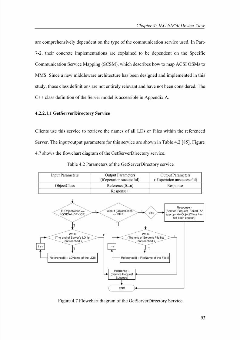
8/8/2019 02chapters1-4
http://slidepdf.com/reader/full/02chapters1-4 93/118
Chapter 4: IEC 61850 Device View
93
are comprehensively dependent on the type of the communication service used. In Part-
7-2, their concrete implementations are explained to be dependent on the Specific
Communication Service Mapping (SCSM), which describes how to map ACSI OSMs to
MMS. Since a new middleware architecture has been designed and implemented in this
study, those class definitions are not entirely relevant and have not been considered. The
C++ class definition of the Server model is accessible in Appendix A.
4.2.2.1.1 GetServerDirectory Service
Clients use this service to retrieve the names of all LDs or Files within the referenced
Server. The input/output parameters for this service are shown in Table 4.2 [85]. Figure
4.7 shows the flowchart diagram of the GetServerDirectory service.
Table 4.2 Parameters of the GetServerDirectory service
END
i ++
While
(The end of Server's LD listnot reached )
T
Reference[i] = LDName of the LD[i]
F
Response +(Service Request
Succeed)
If (ObjectClass ==LOGICAL-DEVICE)
else if (ObjectClass== FILE)
i ++
While
(The end of Server's File listnot reached )
T
Reference[i] = FileName of the File[i]
F
else
Response -(Service Request Failed. Anappropriate ObjectClass has
not been chosen)
T
F
T
F
Figure 4.7 Flowchart diagram of the GetServerDirectory Service
Input Parameters Output Parameters
(if operation successful)
Output Parameters
(if operation unsuccessful)
ObjectClass Reference[0...n] Response-
Response+

8/8/2019 02chapters1-4
http://slidepdf.com/reader/full/02chapters1-4 94/118
Chapter 4: IEC 61850 Device View
94
The GetServerDirectory service can right away point to the address space of the server
due to the fact that server resides at the top of the object tree. Although each physical
device may contain more than a single server, one server per physical device is the
common approach. The service continues by checking the ObjectClass input parameter.
If it holds the string “LOGICAL-DEVICE”, then the ObjectReferences (LDNames) of
all LDs contained within the server will be copied to the return parameter until the end
of server’s LD list is reached. Yet, if it holds the string “FILE”, then the FileNames of
all Files contained within the server will be copied to the return parameter. Otherwise,
the service exists indicating that an appropriate ObjectClass has not been chosen.
4.2.3 The Generic Substation Event
The Generic Substation Event (GSE) model makes it possible to distribute
DataAttribute values efficiently to more than one device in a simultaneous fashion
through the use of multicast/broadcast services. ACSI defines two models for the
exchange of values of a collection of DataAttributes. These are the [84-85]:
(1) Generic Object Oriented Substation Event (GOOSE) model for a wide range of
data exchange, and
(2) Generic Substation State Event (GSSE) model for the exchange of status
information in bit pairs.
The information exchange in both models is based on a publisher/subscriber (multicast)
communication model, which is to be discussed in broad detail in the following chapter
when discussing the middleware design and implementation. Figure 4.8 shows the
building blocks of the GOOSE model.

8/8/2019 02chapters1-4
http://slidepdf.com/reader/full/02chapters1-4 95/118
Chapter 4: IEC 61850 Device View
95
controls
DO
DO
DO
DO
DO
DO
DO
DO
DO
DataObjects in aDataSet
EventMonitor
GOOSE GOOSEControl
GOOSE Handler
Formatting
controls
Get/SetRequest
Get/SetResponse has association to
GOOSE message
Fast GOOSEmessages tosubcribers
GOOSE message
Figure 4.8 GOOSE model
The initiation of the message exchange is identical to the case presented for logging and
reporting. When the values of one or several DataAttributes referenced within a DataSet
change, these values will be formatted into a GOOSE message structure to be
transmitted to a number of recipients. The GOOSE Control Block (GoCB) controls and
regulates the exchange of the GOOSE messages. Hence, the reporting and GOOSE
models have numerous similarities as well as differences. While the reporting model
uses the “point-to-point” communication model, the GOOSE model uses the
“publish/subscribe” counterpart. There is no filtering involved in GOOSE since all
changes regardless of their type are to be included in the GOOSE message. When IEDs
capture the effects of abnormal system conditions within a substation, they express the
details in the form of GOOSE messages. GOOSE replaces the mechanism of
exchanging control signals between IEDs using a fixed, hardwired and sequential data
acquisition infrastructure, which is not capable of meeting the requirements of real time
substation communication systems. IEDs use the information within GOOSE messages
to decide on suitable protection responses to take in response to a particular state change
described by the GOOSE message.

8/8/2019 02chapters1-4
http://slidepdf.com/reader/full/02chapters1-4 96/118
Chapter 4: IEC 61850 Device View
96
The GSSE model is almost identical to the GOOSE model with the only difference
being the format of the information it provides. It can only provide a simple list of status
information expressed in bit pairs. In fact, GGSE model is the GOOSE model described
in UCA 2.0. The whole concept described above for the initiation and transmission of
GOOSE messages is also applicable to the GSSE model.
4.2.3.1 Modelling and Implementing the GOOSE Control Block
The GoCB is used by clients to get/set attributes controlling the operation of the event
monitor and GOOSE handler. Figure 4.9 shows the GoCB class model and its attributes
as defined in Part 7-2 [85]. The C++ class definition of the GoCB model is also
included in Appendix A. The GoCB class model supports five services that permit
clients to perform GoCB related operation such as configuring its attributes.
EA 5.0 Unregistered Trial V
EA 5.0 Unregistered Trial V
EA 5.0 Unregistered Trial V
EA 5.0 Unregistered Trial V
GoCB_Class
+ GoCBName: CosNaming::NameComponent
+ GoCBRef: char [1..255] ([255])
+ GoEna: bool
+ AppID: char [1..65] ([65])
+ DatSet: char [1..255] ([255])
+ ConfRev: unsigned _int32
+ NdsCom: bool
+ SetGoCBValues() : void
+ GetGoCBValues() : void
+ GetGoReference() : void
+ GetGOOSEElementNumber() : void
+ SendGOOSEMessage() : void
Figure 4.9 GoCB class diagram
4.2.3.1.1 SetGoCBValues Service
Clients use this service to set the attribute values of the referenced GoCB. The
input/output parameters for this service are shown in Table 4.3 [85]. Figure 4.10 shows
the flowchart diagram of the SetGoCBValues service.

8/8/2019 02chapters1-4
http://slidepdf.com/reader/full/02chapters1-4 97/118
Chapter 4: IEC 61850 Device View
97
Table 4.3 Parameters of the SetGoCBValues service
END
T
While (found == false)
If (GoCBRef of GoCB[a] ==GoCBReference )
a ++
F
found = true
T
If (GoEna == FALSE )
Set all the attribute values ofthe GoCB according to the
input parameters
Response +(SetGoCBValuesservice request
succeed)
If (the end of this LN'sGoCBList reached)
F
T
F
Create a new GoCB for this LNand then set all the attributevalues according to the input
parameters
T
Response +(SetGoCBValuesservice request
succeed)
Set only the GoEna attributeof the GoCB according to the
GoEnable input parameter
Figure 4.10 Flowchart diagram of the SetGoCBValues service
Once the target LD and LN are located, the SetGoCBValues service searches the current
LN’s GoCB list to determine whether a GoCB with the given GoCBReference has
previously been created or not. If created before and the value of its GoEna attribute is
set to “FALSE”, then all of its attributes are updated. However, if the GoEna attribute is
set to “TRUE” then no changes in the attribute values are allowed except for the GoEna.
Alternatively, if a GoCB can not be located, a new one will be created and added to the
GoCB list of the current LN. Its attribute values will also be initialised based on the
corresponding input parameters
Input Parameters Output Parameters
(if operation successful)
Output Parameters
(if operation unsuccessful)GoCBReference Response+ Response-
FunctionalConstraint
GoEnable
ApplicationID
DataSetReference

8/8/2019 02chapters1-4
http://slidepdf.com/reader/full/02chapters1-4 98/118
Chapter 4: IEC 61850 Device View
98
4.2.3.1.2 GetGoCBValues Service
Clients use this service to get the attribute values of the referenced GoCB [85]. The
input/output parameters for this service are shown in Table 4.4. Figure 4.11 shows the
flowchart diagram of the GetGoCBValues service.
Table 4.4 Parameters of the GetGoCBValues service
ENDT
T
While (found == false)
If (GoCBName of
GoCB[a] == GoCBName )
a ++
F
found = true
Tcopy all the attribute values of the GoCB[a] to
the output parameters, e.g.NeedsCommissioning = NdsCom of GoCB[a]
Response +(Service Request
Succeed)
If (The end of this LN' sGoCBList reached)
F
Figure 4.11 Flowchart diagram of the GetGoCBValues service
4.2.3.1.3 GetGoReference Service
Clients use this service to retrieve the ObjectReferences of specific members of the
DataSet monitored by the referenced GoCB [85]. Table 4.5 shows the input/output
parameters for this service. Figure 4.12 shows the flowchart diagram of the
GetGoReference service.
Input Parameters Output Parameters
(if operation successful)
Output Parameters
(if operation unsuccessful)
GoCBReference GoEnable Response-
FunctionalConstraint ApplicationIDDataSetReference
ConfigurationRevision
NeedsCommissioning
Response+

8/8/2019 02chapters1-4
http://slidepdf.com/reader/full/02chapters1-4 99/118
Chapter 4: IEC 61850 Device View
99
Table 4.5 Parameters of the GetGoReference service
ENDT
T
While (found == false)
If (GoCBName ofGoCB[a] == GoCBName )
a ++
F
found = true
T
DataSetReference = DatSet of GoCB[a]
if (The end of this LN' s
GoCBList reached)
F
DataSetReference== NULL
Response -( DataSetReferencecan not be NULL)
Find target LDusing LDName
Find target LNusing LNName
Split DataSetReference into three strings : LDName,LNName and DataSetName
T
F
T
F
While (found == false)
If (DSRef of DataSet[k] ==DataSetReference )
k ++
Response -(DataSet can not
be found)
F
If (The end of LN ' sDataSetList reached )
T
While (The end of MemberOffsetparameter not reached)
MemberReference[y] =DsMemberRef[MemberOffset[a]] of the DataSet[k]
a++y++
T
T
Response +(Service Request
Succeed)
F
Figure 4.12 Flowchart diagram of the GetGoReference service
The GetGoReference service attains a pointer to the address space of the GoCB making
use of the GoCBReference parameter. It then copies the value of its DatSet attribute to
the DataSetReference dummy variable thus acquiring the ObjectReference of the
DataSet being monitored by this GoCB. Afterwards, it uses this dummy variable when
pointing to the address space of the DataSet. The final stage includes copying the
Input Parameters Output Parameters
(if operation successful)
Output Parameters
(if operation unsuccessful)GoCBReference GoCBReference Response-
MemberOffset [1...n] ConfigurationRevision
MemberReference [1...n]
Response+

8/8/2019 02chapters1-4
http://slidepdf.com/reader/full/02chapters1-4 100/118
Chapter 4: IEC 61850 Device View
100
ObjectReferences of the members of the DataSet, but only those having the index
numbers specified by the MemberOffset input parameter.
4.2.3.1.4 GetGOOSEElementNumber Service
Clients use this service to retrieve the member positions (index) of specific
DataAttribute members of the DataSet associated with the GoCB. Table 4.6 shows the
input/output parameters for this service.
Table 4.6 Parameters of the GetGOOSEElementNumber service
Figure 4.13 shows the flowchart diagram of the GetGOOSEElementNumber service. As
the definition implies, the GetGOOSEElementNumber service is the opposite of the
GetGoReference service where index numbers were given and MemberReferences were
sought. Here, MemberReferences of the DataAttributes are provided and their index
numbers are sought. It points to the GoCB specified by the GoCBReference input
parameter acquiring the value of its DatSet attribute and then using that value to point to
the address space of the DataSet monitored by the GoCB. The final stage involves
searching the DSMemRef list of the pointed DataSet to determine index numbers of the
members specified by the MemberReference parameter. For every single member, the
DSMemRef list is searched until a matching entry is found when its index number is
copied to the return parameter. This service ends once all the members specified in the
MemberReference [1...n] parameter are dealt with.
Input Parameters Output Parameters
(if operation successful)
Output Parameters
(if operation unsuccessful)
GoCBReference GoCBReference Response-
MemberReference[1...n] ConfigurationRevision
MemberOffset[1...n]
Response+

8/8/2019 02chapters1-4
http://slidepdf.com/reader/full/02chapters1-4 101/118
Chapter 4: IEC 61850 Device View
101
END
While (The end of MemberReferencelist not reached)
T
F
While (The end of DataSet[k]'sDSMemRef list not reached)
If (DSMemRef[t] ==MemberReference[a])
MemberOffset[y] = ty++
t++a++
T
F
Response-The MemberReference[a]
couldnot be located
F
T
Response +(Service Request Succeed)
Figure 4.13 Flowchart diagram of the GetGOOSEElementNumber service
4.2.3.1.5 SendGOOSEMessage Service
The SendGOOSEMessage service is used by servers to multicast GOOSE messages,
which have the format shown in Figure 4.14.
AppID
(VISIBLESTRING65)
SqNum(INT32U)
DatSet
(ObjectRef erence)
ConfRev(INT32U)
GoCBReference(ObjectRef erence)
T(TimeStamp)
StNum(INT32U)
Test(Boolean)
NdsCom
(Boolean)
GOOSEData[1..n]
Value
(*)
Figure 4.14 GOOSE message definition
The SendGOOSEMessage service makes use of the publish/subscribe communication
model provided by the underlying data delivery network middleware to accomplish this
task. As soon as a GOOSE message is generated within the server, this service is called
to forward the GOOSE message to the network. The various fields of the GOOSE
message format are as follows [85]:

8/8/2019 02chapters1-4
http://slidepdf.com/reader/full/02chapters1-4 102/118
Chapter 4: IEC 61850 Device View
102
(1) The AppID, a string of 65 characters, is the identifier of the LD where the GoCB
is located,
(2) The DatSet, a string of 255 characters, specifies the DataSetReference of the
DataSet whose values are to be transmitted,
(3) The ConfRev, an unsigned integer of 32 bits, indicates the number of times that
the configuration of the DataSet referenced by the DatSet has been changed,
(4) The SqNum points out the sequence number of each GOOSE generated and sent
by this GoCB. The first GOOSE is to have a SqNum of 1, the second report 2
and so on,
(5) The StNum also an integer contains the counter number, which is incremented
each time a GOOSE message has been sent and a change in the value of a
DataAttribute within the referenced DataSet has been detected,
(6) The GoCBRef contains the ObjectReference of the GoCB,
(7) The T indicates the time when the StNum was incremented,
(8) The Test, if set to TRUE, indicates not to use the contents of the message for
operational purposes,
(9) The NdsCom contains the respective NdsCom attribute of the GoCB, and
(10) The GOOSEData [1...n] contains the values of the DataAttribute members of
the DataSet referenced by the DatSet. Unlike reporting and logging, the DataRef of
the members and ReasonCodes are not included in the GOOSEData.
4.2.3.2 Procedures for GOOSE messaging
This section describes the procedures of event monitoring and GOOSE handling in the
case of GOOSE messaging. The Event_Monitor_GOOSE service carries out the same

8/8/2019 02chapters1-4
http://slidepdf.com/reader/full/02chapters1-4 103/118
Chapter 4: IEC 61850 Device View
103
tasks as its reporting and logging equivalents. Once a GoCB is created, it passes the
ObjectReference of the associated DataSet and the current values of its member
DataAttributes to the Event_Monitor_GOOSE service. The Event_Monitor_GOOSE
service periodically attains the DataAttribute values and calls the GOOSE_Handler
service to format data into a GOOSE message structure in case of changes in the values
of the referenced DataAttributes. The GOOSE_Handler service is much simpler than its
reporting and logging equivalents due to the absence of a filtering mechanism. All types
of changes must be considered equally by the GOOSE model. Hence, new values of the
DataAttribute members of a DataSet are transmitted irrespective of the DataAttributes’
TrgOps. The DataAttribute values constitute the GOOSEData field of a GOOSE
message. All the remaining fields also get filled as appropriate by the GOOSE_Handler
service before the message can be multicast using the SendGOOSEMessage service.
4.2.4 The Transmission of Sampled Values
The transmission of Sampled Values (SV) relates to the fast and cyclic transfer of
samples of measured values from sensor devices such as Current Transformers (CTs)
and Voltage Transformers (VTs). Although reporting and GOOSE models can be used
for any set of data, special attention needs to be paid to the time constraints when
transmitting SV. This has caused the introduction of a new model, the Sampled Values
Model (SVM), for the organised and time-controlled exchange of SV reducing the
combined jitter of sampling and transmission [84-85]. The conceptual illustration of the
SVM is shown in Figure 4.15. The exchange of values of a DataSet is once again at the
heart of this model. However, in this case, the DataAttribute members of the DataSet in
concern are limited to the samples of measured analogue values such as amps and volts.

8/8/2019 02chapters1-4
http://slidepdf.com/reader/full/02chapters1-4 104/118
Chapter 4: IEC 61850 Device View
104
DO
DO
DO
DO
DO
DO
DO
DO
DO
Samples of measured
values in a DataSet
SVMSV Control
SV Handler
Formatting
controls
Get/SetRequest
Get/SetResponse has association to
periodicunicast or
multicast SVmessages
Figure 4.15 SV Model
IEC 61850 defines two control blocks for controlling the exchange of SV. These are the
[85]:
(1) Multicast Sampled Value Control Block (MSVCB) for the transmission of
sampled values using multicast, and
(2) Unicast Sampled Value Control Block (USVCB) for the transmission of
sampled values using unicast.
The multicast mode of transmission is once again based on the publish/subscribe
communication model where subscribers need to add themselves to the subscriber list of
a publisher to be able to receive the periodic updates. In contrast, the unicast mode is
based on a two-party application association that is the client/server model. Each
subscriber, interested in receiving sampled values from a particular publisher, needs to
establish an association with that publisher creating and configuring either a MSVCB or
a USVCB class instance enabling the transmission by setting the SvEna attribute to
TRUE. In both modes, time stamps are added to the values so that subscribers can

8/8/2019 02chapters1-4
http://slidepdf.com/reader/full/02chapters1-4 105/118
Chapter 4: IEC 61850 Device View
105
verify the timeliness of the values. The MSVCB and USVCB classes defined in Part 7-2
are almost identical to each other. Except for the inclusion of a single additional
attribute in the USVCB class, all the remaining attributes and services are common.
Therefore, the only real distinction between the two is the mode of transmission.
4.2.4.1 Modelling and Implementing the Sampled Value Control Block
Clients use the MSVCB model to create and configure instances of MSVCBs for
controlling the communication procedure. Figure 4.16 shows the MSVCB class and its
attributes [85]. The C++ definition of the MSVCB model can be viewed in Appendix A.
The MSVCB class supports three services; two that permit clients to perform MSVCB
related operations and one used by publishers when forwarding SV messages.
ersion
ersion
ersion
ersion
MSVCB_Class
+ MsvCBNam: CosNaming::NameComponent
+ MsvCBRef: char [1..255] ([255])+ SvEna: bool
+ MsvID: char [1..65] ([65])
+ DatSet: char [1..255] ([255])
+ ConfRev: unsigned _int32
+ SmpRate: unsigned _int16
+ OptFlds: PACKET_LIST_SV
+ SetMSVCBValues() : void
+ GetMSVCBValues() : void
+ SendMSVMessage() : void
Figure 4.16 MSVCB class diagram
4.2.4.1.1 SetMSVCBValues service
Clients use this service to set the attribute values of the referenced MSVCB. The
input/output parameters for this service are shown in Table 4.7. The same procedure
described for the case of SetGoCBValues service is also followed precisely when
creating a MSVCB instance and setting its attributes [85].

8/8/2019 02chapters1-4
http://slidepdf.com/reader/full/02chapters1-4 106/118
Chapter 4: IEC 61850 Device View
106
Table 4.7 Parameters of the SetMSVCBValues service
4.2.4.1.2 GetMSVCBValues service
Clients use this service to retrieve the attribute values of the referenced MSVCB. The
input/output parameters for this service are shown in Table 4.8. The GetMSVCBValues
service follows the identical procedure as the GetGoCBValues service. Once the
MSVCB referenced by the MsvCBReference parameter is located, its attribute values
will be copied to the corresponding output parameters. The ConfigurationRevision
parameter returns the value of the ConfRev attribute [85].
Table 4.8 Parameters of the GetMSVCBValues service
4.2.4.1.3 SendMSVMessage service
The SendMSVMessage service is used by publishers to periodically multicast the SV
messages based on the SmpRate making use of the publish/subscribe communication
model provided by the middleware. SV messages have the format shown in Figure 4.17.
Input Parameters Output Parameters
(if operation successful)
Output Parameters
(if operation unsuccessful)MsvCBReference Response+ Response-
FunctionalConstraint
SvEnable
MulticastSampleValueID
DataSetReference
SampleRate
Input Parameters Output Parameters(if operation successful)
Output Parameters(if operation unsuccessful)
MsvCBReference SvEnable Response-
FunctionalConstraint MulticastSampleValueID
DataSetReference
SampleRate
ConfigurationRevision
Response+

8/8/2019 02chapters1-4
http://slidepdf.com/reader/full/02chapters1-4 107/118
Chapter 4: IEC 61850 Device View
107
MsvID(VISIBLE STRING65)
ConfRev(INT32U)
DatSet(ObjectReference)
Sample[1..n]
Value(*)
OptFlds(PACKET_LIST_SV)
SmpCnt(INT16U)
If refresh-time == TRUE
RefrTm(EntryTime)
If sample-synchronized == TRUE
SmpSynch(BOOLEAN)
If sample-rate == TRUE
SmpRate(INT16U)
Figure 4.17 SV message format
The various fields of the SV message format are as follows [85]:
(1) The MsvID, a string of 65 characters, contains the value of the corresponding
MsvID attribute of the MSVCB,
(2) The OptFlds is derived from the respective OptFlds attribute of the MSVCB,
(3) The DatSet, a string of 255 characters, specifies the DataSetReference of the
DataSet whose values are to be transmitted,
(4) The Sample [1...n] contains the values of the DataAttribute members of the
DataSet referenced by the DatSet sampled at a given time,
(5) The SmpCnt, an unsigned integer of 16 bits, indicates how many samples of an
analogue value have been taken. Each time a new sample is taken, SmpCnt will
be incremented. ConfRev contains the value of the corresponding ConfRev
attribute of the MSVCB,
(6) The RefrTm points out the last transmission buffer update time, and
(7) The SmpSynch, if set to TRUE, indicates that the sampled values have been
synchronised by the clock signals and the SmpRate contains the value of the
corresponding SmpRate attribute of the MSVCB.

8/8/2019 02chapters1-4
http://slidepdf.com/reader/full/02chapters1-4 108/118
Chapter 4: IEC 61850 Device View
108
4.2.4.2 Procedures for SV messaging
The design and implementation details of the MSV_Handler service, designed to
perform the tasks of the SV handler, are provided in this subsection. The main task of
the SV handler is to sample the values of the DataAttribute members of a DataSet at
periodic intervals based on the SmpRate attribute of the MSVCB formatting them into a
SV message structure. As it was in the case of GOOSE messaging, there is no need for
any filtering. Unlike reporting and GOOSE, the information exchange is not initiated by
changes in the values of the DataAttribute members of the DataSet associated with the
MSVCB. Whether values change or not, they get sampled periodically and forwarded to
subscribers. Figure 4.18 shows the flowchart diagram of the MSV_Handler service.
When a MSVCB is created, it calls the MSV_Handler service and passes the value of its
DatSet attribute to the service as an input argument. Subsequently, the DataSet list of
the target LN is searched until a successful DataSet entry is located. The successful
entry would have the value of its DSRef attribute set same as the value of the received
DatSet attribute. The service then searches the MSVCB list of the LLNO until an entry
associated with the located DataSet is found. The service moves on and copies the
values of all the attributes of the located MSVCB to a number of local variables. It also
obtains the values of all the DataAttribute members of the DataSet, which was
previously located. Finally, it creates a SV message and copies the previously obtained
values to the necessary fields of the message. Once all the fields are filled, the SV
message gets forwarded to the subscribers using the SendMSVMessage service.
The concept of Multi-Threading, which was described in detail in Chapter 3, is also
utilised by the MSV_Handler service. A new thread is created at the end of each run

8/8/2019 02chapters1-4
http://slidepdf.com/reader/full/02chapters1-4 109/118
Chapter 4: IEC 61850 Device View
109
that starts the execution of the same service after a fixed interval. The interval depends
on the SmpRate attribute of the MSVCB. As a result, the MSV_Handler service
continues its execution in the background periodically obtaining the values of the
DataAttribute members of the DataSet and forwarding them to the subscribers.
Find target LD using LDName and target LN using LNName
END
T
F
While (found == false)
If (DSRef of DataSet[l] ==DataSetReference )
l ++Response -
(DataSet can not befound)
F
T
If (The end of LN ' sDataSetList reached )
T
T
F
While (found == false)
If (DatSet of MSVCB[a] ==DataSetReference )
a ++
Response -(MSVCB can not
be found)
F
T
If (The end of LLNO ' sMSVCBList reached )
T
Get the values of all the attributes of the
MSVCB[a], e.g.ConfRev= ConfRev of MSVCB[a]
Get the values of all the members of theDataSet[l]
create the SV messagefill all the fields as appropriate, e.g.SmpRate = SmpRate of MSVCB[a]
Sample[1..n] = values of all the members of the DataSet[l]
pause for 1/SmpRate
create a new thread and pass theDataSetReference to the thread
_beginthread (.........)
Figure 4.18 Flowchart diagram of the MSV_Handler service

8/8/2019 02chapters1-4
http://slidepdf.com/reader/full/02chapters1-4 110/118
Chapter 4: IEC 61850 Device View
110
4.2.5 The Setting Group Control Block Model
The Setting Group Control Block (SGCB) model is a special treatment for setting data
contained in LNs. Although an instance of a data can only have a single value, it might
be necessary to store several values for that instance that can be used one at a time. The
SGCB model makes it possible to store and edit several values for one or more data and
also to switch between the values. A set of values defined for several data form a
Setting Group (SG). The setting data can have as many values as the number of defined
SGs. The values of a specific SG can only be set when that group is in the “EDIT”
state. Once the values are set, they can be selected for use by the application by
switching that group to the “ACTIVE” state. The SGCB model is depicted in the
example shown in Figure 4.19 [84-85].
LN PPAM......
Settings
Phase Start Value PhsStartGround Start Value GndStartOperate Delay Time OpTimDel
Reset Delay Time RsTimDel
10
3
4
Logical Node Active buffer
Setting data
SG Control Block
#2
#3
#1
#2
P h s S t a r t
G n d S t a r t
O p T i m D e l
R s T i m D e l
1 0 3 4
1 0 2 1
1 3 2 3#3
#1
1 3 2 3
SelectEditSG #3 ConfirmEditSGValues
DataName
Data value
Total number of SG=3
SGActive
settinggroup = #1
#3
G
e t S G V a l u e s
S e l e c t A c
t i v e S G
G e t S G C B V a l u e s
Edit buffer
S e t S G V a l u e s ,
C o n f i r m E d i t S G V a l u e s
G e t S G V a l u e s
Settinggroup #3can be
edited
SelectEditSG #3
Figure 4.19 Basic model of the SGCB

8/8/2019 02chapters1-4
http://slidepdf.com/reader/full/02chapters1-4 111/118
Chapter 4: IEC 61850 Device View
111
The PPAM (phase angle relay) LN comprises four settings data:
• PhsStart,
• GndStart,
• Primed, and
• RsTimDel.
The SGCB “SG Control” provides three SGs (#1, #2, #3) each with independent values
for the three data. The members of the active SG are referenced by the
ObjectReferences of the data with functional constraint “SG” and members of the SG in
the edit buffer are referenced by the ObjectReferences of the data with functional
constraint “SE”. The values of the data are derived from the values of one of the three
SGs by using the multiplex on the left. The SelectActiveSG service determines the
values of which SG should be copied to the active buffer to be used by the PPAM LN.
In the example, SG #1 has been set to be in the “ACTIVE” state. The SelectEditSG
service determines the values of which SG should be copied to the edit buffer. When in
the edit buffer, the values of a SG can be set and get (SetSGValues and GetSGValues).
Once the new values are set, the client has to confirm using the ConfrimEditSGValues
service before the new values can be taken over by the selected SG (SG #3).
4.2.5.1 Modelling and Implementing the Setting Group Control Block
Figure 4.20 shows the SGCB class model and its attributes. Clients use the SGCB class
to create SGCB instances, which allow them to control the operation of the SGCB
model through a number of services. SGCB instances enable clients to create SGs, edit
their values and choose which SG to be in the edit buffer and which SG to be in the
active buffer [85]. The C++ definition of the SGCB class can be viewed in Appendix A.

8/8/2019 02chapters1-4
http://slidepdf.com/reader/full/02chapters1-4 112/118
Chapter 4: IEC 61850 Device View
112
on EA 5.0 Unregistered Trial
on EA 5.0 Unregistered Trial
on EA 5.0 Unregistered Trial
on EA 5.0 Unregistered Trial
on EA 5.0 Unregistered Trial
SGCB_Class
+ SGCBName: CosNaming::NameComponent
+ SGCBRef: char [1..255] ([255])
+ NumOfSG: unsigned _int8+ ActSG: unsigned _int8
+ EditSG: unsigned _int8
+ CnfEdit: bool
+ LActTm: Time_Stamp
+ SelectActiveSG() : void
+ SelectEditSG() : void
+ ConfirmEdi tSGValues() : void
+ SetSGValues() : void
+ GetSGValues() : void
+ GetSGCBValues() : void
Figure 4.20 SGCB class diagram
4.2.5.1.1 SelectActiveSG Service
Clients use this service to set the value of the ActSG attribute of the referenced SGCB
loading the values of the specified SG into the active buffer [85]. The input/output
parameters for this service are shown in Table 4.9.
Table 4.9 Parameters of the SelectActiveSG service
Figure 4.21 shows the flowchart diagram of the SelectActiveSG service. Once the LD is
located, the service progresses into setting the value of the ActSG attribute of the SGCB
to the value of the SettingGroupNumber parameter. There is no need to search for either
the LN or the SGCB since only a single SGCB resides within the LLNO and the
location of the LLNO is known to the program. Hence, the program can straight away
jump to the address space of the single SGCB contained within the LLNO. Once the
ActSG attribute is set, the values of the SG having the index number
Input Parameters Output Parameters(if operation successful)
Output Parameters(if operation unsuccessful)
SGCBReference Response+ Response-
SettingGroupNumber

8/8/2019 02chapters1-4
http://slidepdf.com/reader/full/02chapters1-4 113/118
Chapter 4: IEC 61850 Device View
113
“SettingGroupNumber” will be moved into the active buffer where the DataAttribute
values are overwritten with these values.
SGCBReference== NULL
Response -(SGCBReference can
not be NULL)
Find target LDusing LDName
Seperate SGCBReference into three strings : LDName,LNName and SGCBName
T
F
ActSG = SettingGroupNumber
Values of the SG #SettingGroupNumber --> activebuffer
Values of the DataAttributes = Values in the activebuffer
Response +(Service Request
Succeed)
END
Figure 4.21 Flowchart diagram the SelectActiveSG service
4.2.5.1.2 SelectEditSG Service
Clients use this service to set the value of the EditSG attribute of the referenced SGCB
loading the values of the specified SG into the edit buffer. The input/output parameters
for this service are shown in Table 4.10 [85]. This service is similar to the previous one
except that the value of the EditSG attribute will be set and values of the SG with the
index number “SettingGroupNumber” will be moved into the edit buffer.
Table 4.10 Parameters of the SelectEditSG service
Input Parameters Output Parameters(if operation successful)
Output Parameters(if operation unsuccessful)
SGCBReference Response+ Response-
SettingGroupNumber

8/8/2019 02chapters1-4
http://slidepdf.com/reader/full/02chapters1-4 114/118
Chapter 4: IEC 61850 Device View
114
4.2.5.1.3 SetSGValues Service
Clients use this service to set the values of the SG in the edit buffer [85]. The
input/output parameters for this service are shown in Table 4.11. Figure 4.22 shows the
flowchart diagram of the SetSGValues service.
Table 4.11 Parameters of the SetSGValues service
Response -(The referenced Data can not be
located in the edit buffer)
END
If (DataName [x] in the edit buffer== FCDA )
break
T
Edit_Buffer [x] = DataAttributeValue
for (x=0; x< 30; x ++)
F
Response +(Service Request Succeed)
T
F
If ( FC == "SE")Response -
(Check the FC value)F
T
Figure 4.22 Flowchart diagram of the SetSGValues service
Once the target LD is located, the service moves its pointer to the edit buffer of the
SGCB contained within the referenced LD. Since there is a single SGCB in each LD
and each SGCB is associated with a single edit buffer, this can be accomplished without
looping, in other words, without needing to search any lists. The service continues by
searching the edit buffer to find the data specified by the Reference parameter. A “for”
Input Parameters Output Parameters
(if operation successful)
Output Parameters
(if operation unsuccessful)
Reference Response+ Response-
DataAttributeValue

8/8/2019 02chapters1-4
http://slidepdf.com/reader/full/02chapters1-4 115/118
Chapter 4: IEC 61850 Device View
115
loop was used for this purpose as shown in Figure 4.22. If a matching entry is located in
the edit buffer, its value will be adjusted relative to the DataAttributeValue parameter
once the service confirms that the FC received in the request holds the string “SE”. If a
matching data can not be located, the service exits with an appropriate service error.
4.2.5.1.4 ConfirmEditSGValues Service
Clients use this service to confirm that the new values of the SG set using the
SetSGValues service should overwrite its old values. The input/output parameters for
this service are shown in Table 4.12 [85]. Figure 4.23 shows the final part of the
flowchart diagram of the ConfirmEditSGValues service.
Table 4.12 Parameters of the ConfrimEditSGValues service
CnfEdit attribute of the SGCB = true
Response +
(Service Request Succeed)for (x=0; x< 30; x ++)
T
F
SGValues [ EditSG] [x] = Edit_Buffer [x]
Figure 4.23 Flowchart diagram of the ConfirmEditSGValues service
Once the target SGCB is located based on the SGCBReference parameter, the service
attains a pointer to the SGCB. First, the CnfEdit attribute of the SGCB is set to true
confirming the editing process. Then, all values of the SG with the index number
Input Parameters Output Parameters(if operation successful)
Output Parameters(if operation unsuccessful)
SGCBReference Response+ Response-

8/8/2019 02chapters1-4
http://slidepdf.com/reader/full/02chapters1-4 116/118
Chapter 4: IEC 61850 Device View
116
“SettingGroupNumber” will be updated based on the values in the edit buffer. The
SettingGroupNumber is not an input parameter, yet its value can be obtained from the
EditSG attribute of the SGCB. A “for” loop was used once again because the maximum
number of values a SG can hold is known to be 30.
4.2.5.1.5 GetSGCBValues Service
Clients use this service to retrieve the attribute values of a referenced SGCB. The
input/output parameters for this service are shown in Table 4.13 [85]. Once the target
SGCB is located and the value of the FC received in the request is verified, the service
copies the attribute values of the referenced SGCB to the output parameters to be
returned to the caller program.
Table 4.13 Parameters of the GetSGCBValues service
4.2.5.1.6 GetSGValues Service
Clients use this service to get the value of a particular DataAttribute of a SG [85]. The
input/output parameters for this service are shown in Table 4.14. Figure 4.24 shows the
flowchart diagram of the GetSGValues service.
Table 4.14 Parameters of the GetSGValues service
Input Parameters Output Parameters
(if operation successful)
Output Parameters
(if operation unsuccessful)
SGCBReference Response+ Response-
FunctionalConstraint NumberOfSettingGroup
ActiveSettingGroup
EditSettingGroup
LastActiveTime
Input Parameters Output Parameters(if operation successful)
Output Parameters(if operation unsuccessful)
Reference Response+ Response-
DataAttributeValue

8/8/2019 02chapters1-4
http://slidepdf.com/reader/full/02chapters1-4 117/118
Chapter 4: IEC 61850 Device View
117
Response -(The referenced Data can not be
located in the edit buffer)
END
If (DataName [x] in the edit buffer== FCDA )
break
T
DataAttributeValue = Edit_Buffer [x]
for (x=0; x< 30; x ++)
F
Response +(Service Request Succeed)
T
F
If ( FC == "SE")
T
If ( FC == "SG")Response -
(Check the FC value)
DataAttributeValue = Active_Buffer [x]
T
FF
Figure 4.24 Flowchart diagram of the GetSGValues service
Once the target LD is located, the service searches the edit buffer to find the position
number (x) of the data specified by the Reference parameter. All data have the same
line-up whether in the edit buffer or the active buffer. Hence, the found position number
will be the same regardless whether the edit buffer or the active buffer is searched. The
service then checks the value of the FC received in the request. If it equates to “SE”,
then the value of the data in the edit buffer will be copied to the DataAttribute return
parameter. However, if it equates to “SG”, then the value of the data in the active buffer
is copied to the output parameter. Otherwise, the service ends indicating that the value
of the FC received in the request has been incorrectly specified.

8/8/2019 02chapters1-4
http://slidepdf.com/reader/full/02chapters1-4 118/118
Chapter 4: IEC 61850 Device View
4.3 Conclusion
In this chapter, the modelling and implementation of the IEC 61850 standard’s device-
view OSMs has been presented. Chapter 4 carries on from Chapter 3 and completes the
discussion of the standard’s ACSI models. In this chapter, the main centre of attention
has been on the ACSI device-view models and their associated services as well as the
standalone service models defined in ACSI for the peer-to-peer distribution of time
critical IED data. Device-view models describe device functionality by specifying the
syntax and semantics of the data exchanged and also the dynamic behaviour of devices.
The Logical Device (LD) and Server class models are the two important building blocks
constituting the IEC 61850 standard’s device-view constituent. This chapter has
provided broad discussion on the OO implementation of these class models and their
associated services.
In addition to the Server and LD class models, the IEC 61850 standard’s device-view
constituent comprise of additional standalone service models for which special attention
needs to be paid. The most significantly valued of all, the GOOSE model, enables fast


![Oh Pretty Woman4sc].pdfã ### ### ### ### ### ### ### ### 4 4 4 4 4 4 4 4 4 4 4 4 4 4 4 4 4 4 4 2 4 2 4 2 4 2 4 2 4 2 4 2 4 2 4 2 4 4 4 4 4 4 4 4 4 4 4 4 4 4 4 4](https://static.fdocuments.in/doc/165x107/60cfb349cd0cbb00d32b6774/oh-pretty-woman-4scpdf-4-4-4-4-4-4-4-4-4-4.jpg)


![Finale 2005a - [Untitled1]h).pdf · 2014-02-18 · 4 4 4 4 4 4 4 4 4 4 4 4 4 4 4 4 4 4 4 4 4 4 4 4 4 4 4 4 4 4 4 4 4 4 4 4 4 4 4 4 4 4 4 4 4 4 4 4 4 4 Picc. Flutes Oboe Bassoon Bb](https://static.fdocuments.in/doc/165x107/5b737b707f8b9a95348e2e6f/finale-2005a-untitled1-hpdf-2014-02-18-4-4-4-4-4-4-4-4-4-4-4-4-4-4.jpg)


