
02765_B
38
Installation and Operation Manual Gas Engine I/O Node 9906-129 Hardware Only Manual 02765 (Revision A)
-
Upload
maureen-moss -
Category
Documents
-
view
219 -
download
0
Transcript of 02765_B
8/2/2019 02765_B
http://slidepdf.com/reader/full/02765b 1/38
Installation and Operation Manual
Gas Engine I/O Node
9906-129Hardware Only
Manual 02765 (Revision A)
8/2/2019 02765_B
http://slidepdf.com/reader/full/02765b 2/38
DEFINITIONS
This is the safety alert symbol. It is used to alert you to potential personalinjury hazards. Obey all safety messages that follow this symbol to avoidpossible injury or death.
• DANGER —Indicates a hazardous situation which, if not avoided, will result in deathor serious injury.
• WARNING —Indicates a hazardous situation which, if not avoided, could result indeath or serious injury.
• CAUTION —Indicates a hazardous situation which, if not avoided, could result inminor or moderate injury.
• NOTICE —Indicates a hazard that could result in property damage only (includingdamage to the control).
• IMPORTANT —Designates an operating tip or maintenance suggestion.
The engine, turbine, or other type of prime mover should be equipped with anoverspeed shutdown device to protect against runaway or damage to the primemover with possible personal injury, loss of life, or property damage.
The overspeed shutdown device must be totally independent of the prime movercontrol system. An overtemperature or overpressure shutdown device may alsobe needed for safety, as appropriate.
Read this entire manual and all other publications pertaining to the work to be performed beforeinstalling, operating, or servicing this equipment. Practice all plant and safety instructions andprecautions. Failure to follow instructions can cause personal injury and/or property damage.
This publication may have been revised or updated since this copy was produced. To verify thatyou have the latest revision, be sure to check the Woodward website:
www.woodward.com/pubs/current.pdfThe revision level is shown at the bottom of the front cover after the publication number. The latestversion of most publications is available at:
www.woodward.com/publicationsIf your publication is not there, please contact your customer service representative to get thelatest copy.
Any unauthorized modifications to or use of this equipment outside its specified mechanical,
electrical, or other operating limits may cause personal injury and/or property damage, includingdamage to the equipment. Any such unauthorized modifications: (i) constitute "misuse" and/or"negligence" within the meaning of the product warranty thereby excluding warranty coveragefor any resulting damage, and (ii) invalidate product certifications or listings.
To prevent damage to a control system that uses an alternator or battery-chargingdevice, make sure the charging device is turned off before disconnecting the batteryfrom the system.
To prevent damage to electronic components caused by improper handling, readand observe the precautions in Woodward manual 82715, Guide for Handling and Protection of Electronic Controls, Printed Circuit Boards, and Modules .
Woodward Governor Company reserves the right to update any portion of this publication at any time. Informationprovided by Woodward Governor Company is believed to be correct and reliable. However, no responsibility is assumedby Woodward Governor Company unless otherwise expressly undertaken.
© Woodward 1996All Rights Reserved
8/2/2019 02765_B
http://slidepdf.com/reader/full/02765b 3/38
Manual 02765 Gas Engine I/O Node
Woodward i
Contents
ELECTROSTATIC DISCHARGE AWARENESS ..................................................III CHAPTER 1. GENERAL INFORMATION........................................................... 1 Introduction ............................................................................................................. 1 Declaration of Incorporation ................................................................................... 1 Hardware ................................................................................................................ 1 Application .............................................................................................................. 2 CHAPTER 2. INSTALLATION.......................................................................... 5 Unpacking ............................................................................................................... 5 Power Requirements .............................................................................................. 5 Location Considerations ......................................................................................... 5 Internal Jumpers ..................................................................................................... 5 Rotary Switch Settings ........................................................................................... 7 Shielded Wiring ...................................................................................................... 7 Power Supply (Terminals 2/3) ................................................................................ 7 Relay Output (Terminals 4/5/6) .............................................................................. 8 Aux Contact (Terminals 7/8) ................................................................................... 8 Stepper Motor Driver (Terminals 10/11/12/13) ....................................................... 8 Lambda Sensor Input (Terminals 15/16) .............................................................. 11 Lambda Sensor Supply (Terminals 17/18) ........................................................... 15 Potentiometer Input (Terminals 20/21/22) ............................................................ 15 MAP Sensor Input (Terminals 24/25/26) .............................................................. 16 MAT Sensor Input (Terminals 28/29/30) .............................................................. 17 RTD #2 or Analog Input #2 (Terminals 32/33/34) ................................................ 18 RTD #1 or Analog Input #1 (Terminals 36/37/38) ................................................ 19 LON Communication Channel (Terminals 40/41/42) ........................................... 19 CHAPTER 3. SERVICE OPTIONS ................................................................. 22 Product Service Options ....................................................................................... 22 Woodward Factory Servicing Options .................................................................. 23 Returning Equipment for Repair ........................................................................... 24
Replacement Parts ............................................................................................... 24 Engineering Services ............................................................................................ 25 How to Contact Woodward ................................................................................... 25 Technical Assistance ............................................................................................ 26 APPENDIX A. PART NUMBER LIST.............................................................. 27 APPENDIX B. CONTROL WIRING DIAGRAM ................................................. 28 APPENDIX C. GAS ENGINE I/O NODE SPECIFICATION ................................. 31
8/2/2019 02765_B
http://slidepdf.com/reader/full/02765b 4/38
Gas Engine I/O Node Manual 02765
ii Woodward
Illustrations and Tables
Figure 1-1. Outline Drawing of the Gas Engine I/O Node ......................................3 Figure 1-2. Typical Layout of the Gas Engine I/O Node and its Auxiliary Devices 4 Figure 2-2. Lambda/Slew Box ................................................................................9 Figure 2-3. Gas Control Valve Connector with Shielded Cable ............................. 9 Figure 2-4. Gas Control Valve ..............................................................................10 Figure 2-5. UEGO Sensor Kit ...............................................................................11 Figure 2-6. Thermal Characteristics of the UEGO Sensor ...................................12 Figure 2-7. UEGO Sensor ....................................................................................13 Figure 2-8. Mounting of the UEGO Sensor in the Exhaust Pipe ..........................13 Figure 2-9. UEGO Controller ................................................................................15 Figure 2-10. MAP Sensor Connector with Shielded Cable ..................................16 Figure 2-11. Manifold Absolute Temperature Sensor ..........................................16 Figure 2-12. MAT Connection on the Terminals ..................................................17 Figure 2-13. Manifold Absolute Temperature Sensor ..........................................18 Figure 2-14. Typical LON Setup ...........................................................................19 Figure 2-15. Location of the Network LEDs and ID Switch ..................................20 Figure A-1. Gas Engine I/O Node Control Wiring Diagram ..................................30

8/2/2019 02765_B
http://slidepdf.com/reader/full/02765b 5/38
Manual 02765 Gas Engine I/O Node
Woodward iii
Electrostatic Discharge Awareness
All electronic equipment is static-sensitive, some components more than others.To protect these components from static damage, you must take specialprecautions to minimize or eliminate electrostatic discharges.
Follow these precautions when working with or near the control.
1. Before doing maintenance on the electronic control, discharge the staticelectricity on your body to ground by touching and holding a grounded metalobject (pipes, cabinets, equipment, etc.).
2. Avoid the build-up of static electricity on your body by not wearing clothingmade of synthetic materials. Wear cotton or cotton-blend materials as muchas possible because these do not store static electric charges as much assynthetics.
3. Keep plastic, vinyl, and Styrofoam materials (such as plastic or Styrofoamcups, cup holders, cigarette packages, cellophane wrappers, vinyl books orfolders, plastic bottles, and plastic ash trays) away from the control, themodules, and the work area as much as possible.
4. Do not remove the printed circuit board (PCB) from the control cabinetunless absolutely necessary. If you must remove the PCB from the controlcabinet, follow these precautions:
• Do not touch any part of the PCB except the edges.
• Do not touch the electrical conductors, the connectors, or thecomponents with conductive devices or with your hands.
• When replacing a PCB, keep the new PCB in the plastic antistaticprotective bag it comes in until you are ready to install it. Immediatelyafter removing the old PCB from the control cabinet, place it in theantistatic protective bag.
To prevent damage to electronic components caused by improperhandling, read and observe the precautions in Woodward manual82715, Guide for Handling and Protection of Electronic Controls,Printed Circuit Boards, and Modules .

8/2/2019 02765_B
http://slidepdf.com/reader/full/02765b 6/38
Gas Engine I/O Node Manual 02765
iv Woodward

8/2/2019 02765_B
http://slidepdf.com/reader/full/02765b 7/38
Manual 02765 Gas Engine I/O Node
Woodward 1
Chapter 1.General Information
Introduction
This manual describes the Woodward Gas Engine I/O Node, part number9906-129. The combined use of this information will provide adequateinformation for the installation, operation and maintenance of the device,including its auxiliary hardware.
Use of this equipment by untrained or unqualified personnel couldresult in damage to the node or the installation's equipment andpossible loss of life or personal injury. Make sure personnel using orworking on this equipment are properly trained.
• Before operating the unit after installation verify the following:• Check all wiring for proper connections (see the control wiring diagram in
Appendix B).• Check the power sources for proper voltages and proper connections (see
Chapter 2).
Declaration of Incorporation
In accordance with the EMC Directive 89/336/EEC and its amendments, thiscontrolling device, manufactured by the Woodward Governor Company, isapplied solely as a component to be incorporated into an engine prime moversystem. Woodward Governor declares that this controlling device complies withthe requirements of EN50081-2 and EN50082-2 when put into service per theinstallation and operating instructions outlined in the product manual.
NOTICE: This controlling device is intended to be put into service only uponincorporation into an engine prime mover system that itself has met therequirements of the above Directive and bears the CE mark.
Hardware
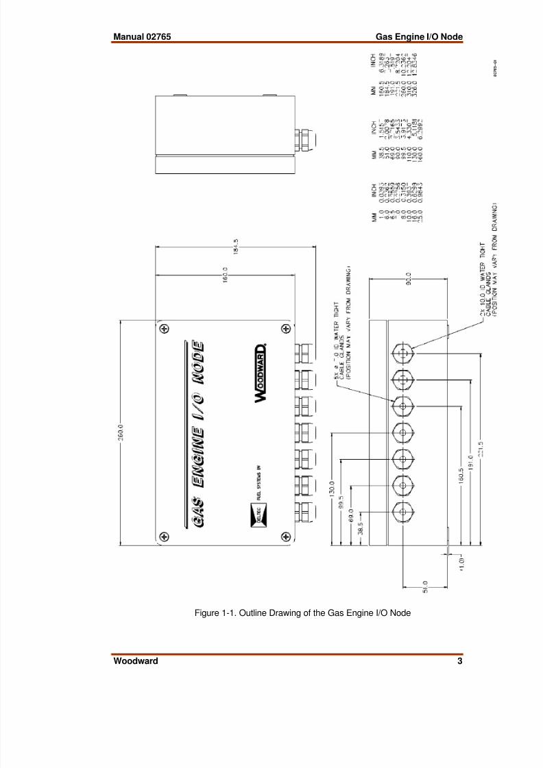
The Gas Engine I/O Node (Figure 1-1) consists of a single printed circuit board ina metal chassis with seven water tight cable glands. Connections are via twoterminal blocks. The Gas Engine I/O Node can be mounted in a control cabinetor in a convenient location in the vicinity of the gas engine that meets thetemperature and vibration specifications.
The Gas Engine I/O Node requires a power supply input voltage, with 40 Wattsas the nominal power consumption at rated voltage:• 18-40 Vdc (24 Vdc nominal)

8/2/2019 02765_B
http://slidepdf.com/reader/full/02765b 8/38
Gas Engine I/O Node Manual 02765
2 Woodward
Application
The Gas Engine I/O Node in combination with 723 DCS can be used for lean-burn gas engines running in both “closed or open loop” air fuel ratio control andfor stoichiometric gas engines, naturally aspirated or turbocharged in the powerrange of 20 to 2000 kW. In case of a V-engine, air fuel ratio control per bank ispossible using two Gas Engine I/O Nodes and a 723 DCS, one for each bank.
The Gas Engine I/O Node itself is not suitable to do the air fuel ratio control.
The Gas Engine I/O Node is specially designed to do the air fuel ratio control oncarbureted turbocharged or non turbocharged gas engines. The Gas Engine I/ONode is receiving and sending air fuel ratio related parameters to the 723 DCSvia the network using the LONTalk® protocol, an Echelon® CorporationLonWorks® network.
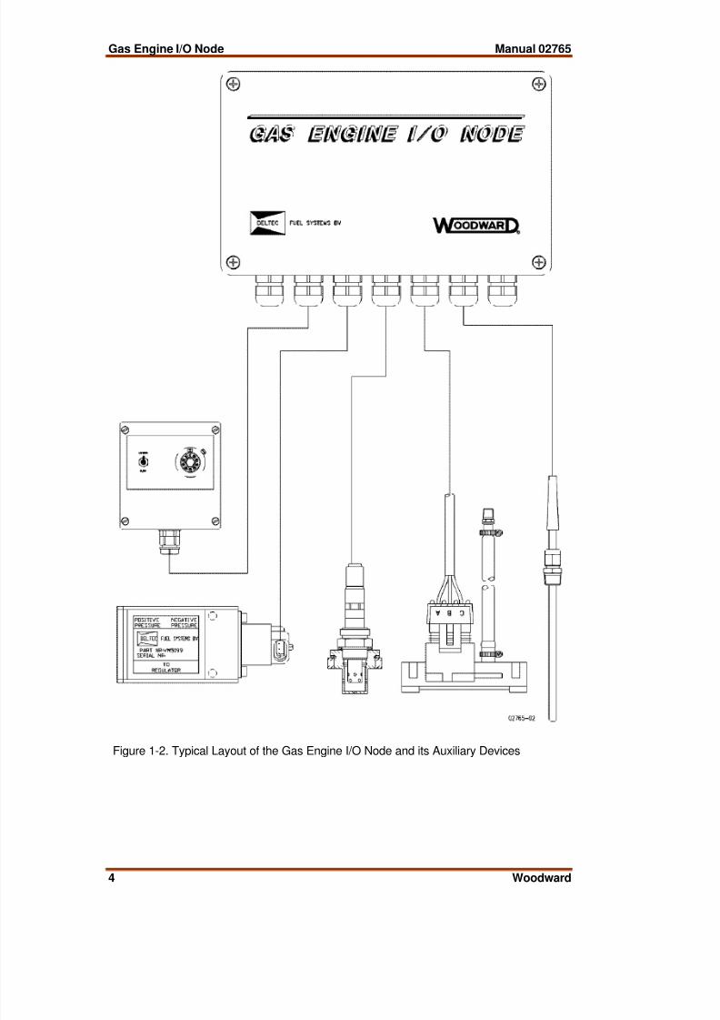
The engine skid mounting capability of the Gas Engine I/O Node makes itpossible to mount it close to the engine, saving a lot of wiring installation. Only atwisted pair shielded cable is needed to communicate with the 723 DCS. Figure1-2 shows a typical lay-out of the Gas Engine I/O Node with its auxiliary devices.
The Gas Engine I/O Node is programmed to suit air fuel ratio control applicationsrequiring the following inputs and outputs:• Relay output
• Aux. contact input
• Stepper motor output• Lambda sensor and supply
• Potentiometer input (10kΩ 10 turns)• Manifold Absolute Pressure (MAP) Sensor
• Manifold Absolute Temperature (MAT) Sensor
• RTD #2 or Analogue input #2 Sensor
• RTD #1 or Analogue input #1 Sensor• The LON channel
8/2/2019 02765_B
http://slidepdf.com/reader/full/02765b 9/38
Manual 02765 Gas Engine I/O Node
Woodward 3
Figure 1-1. Outline Drawing of the Gas Engine I/O Node
8/2/2019 02765_B
http://slidepdf.com/reader/full/02765b 10/38
Gas Engine I/O Node Manual 02765
4 Woodward
Figure 1-2. Typical Layout of the Gas Engine I/O Node and its Auxiliary Devices
8/2/2019 02765_B
http://slidepdf.com/reader/full/02765b 11/38
Manual 02765 Gas Engine I/O Node
Woodward 5
Chapter 2.Installation
Unpacking
Before handling the control, read page iii, Electrostatic Discharge Awareness. Becareful when you unpack the electronic control. Check the Gas Engine I/O Nodeand its auxiliary hardware for signs of damage such as scratches, and loose orbroken parts. If any damage is found, immediately notify the shipper.
Power Requirements
The Gas Engine I/O Node requires a voltage source of 18 to 40 Vdc.
To prevent damage to the node, do not exceed the input voltagerange.
If a battery is used for operating power, an alternator or otherbattery-charging device is necessary to maintain a stable supplyvoltage.
To prevent damage to the node, make sure that the alternator orother battery-charging device is turned off or disconnected beforedisconnecting the battery from the node.
Location ConsiderationsConsider these requirements when selecting the mounting location:• adequate ventilation for cooling
• space for servicing and repair
• protection from direct exposure to water or to a condensation-proneenvironment
• protection from high-voltage or high-current devices, or devices whichproduce electromagnetic interference
• avoidance of vibration• selection of a location that will provide an operating temperature range of –
40 to +70 °C (–40 to +158 °F)
The node must NOT be mounted on the engine, only mounting on the engineskid is allowed.
Internal Jumpers
The Gas Engine I/O Node has six, two-position internal jumpers (JPR1 & JPR2,JPR3 & JPR4, JPR5 & JPR7, JPR6 & JPR8, JPR10 & JPR11, JPR13 & JPR14)located on the top of the printed circuit board. If it is necessary to change any
jumper to match your control requirements, and this suits the nature of thesoftware, be sure to read page iii, Electrostatic Discharge Awareness.

8/2/2019 02765_B
http://slidepdf.com/reader/full/02765b 12/38
Gas Engine I/O Node Manual 02765
6 Woodward
Remove the Gas Engine I/O Node cover, with the power off. Remove the fivescrews, to take the EMI shield off. Also carefully remove the appropriate jumperwith your fingers or a small pair of tweezers. and replace it securely over theproper two connectors (see Figure 2-1).
The jumper connections are listed:
** JPR6 & JPR5 & JPR14 RTD Input #1
** JPR1 & JPR3 & JPR10 RTD Input #2
JPR8 & JPR7 & JPR13 Analogue Input #1 0-5 VdcJPR2 & JPR4 & JPR11 Analogue Input #2 0-5 Vdc
** default jumper setting
Figure 2-1. Gas Engine I/O Node Internal Jumpers and Rotary Switches

8/2/2019 02765_B
http://slidepdf.com/reader/full/02765b 13/38
Manual 02765 Gas Engine I/O Node
Woodward 7
Rotary Switch Settings
The module address circuit reads the selected module address from the rotaryswitches on each node. This address should correspond to the address of the I/Omodule hardware in the application program. If these rotary switches are setincorrectly, the node will not communicate with the 723 DCS and a LONcommunication error will be annunciated through the application program. If thenode address switches are changed, power to the module must be cycled beforeit will read the new module address and change its communication accordingly.
In case of a V-engine where the air fuel ratio per bank is controlled by means oftwo Gas Engine I/O Nodes and one 723 DCS, rotary switches RSW1 & RSW2should be set differently. In this case the left bank of the V-engine will have itsnode address set on 00 (RSW1=0 & RSW2 = 0) and the right bank will have itsnode address set on 01 (RSW1=0 & RSW2 = 1). See Figure 2-1 for the rotaryswitch settings.
Shielded Wiring
All shielded cables must be twisted conductor pairs. Do not attempt to tin thebraided shield. All signal lines should be shielded to prevent picking up straysignals from adjacent equipment. Connect the shields to the nearest chassisground. Wire exposed beyond the shield itself should be as short as possible, notexceeding 50 mm (2 inches). The other end of the shields must be left open andinsulated from any other conductor. DO NOT run shielded signal wires along withother wires carrying large currents. See Woodward application note 50532,Interference Control in Electronic Governing Systems , for more information.
Where shielded cable is required, cut the cable to the desired length and preparethe cable as instructed below.
• Strip outer insulation from one end, exposing the braided or spiral wrappedshield. DO NOT CUT THE SHIELD.
• Using a sharp, pointed tool, carefully spread the strands of the shield.• Pull inner conductor(s) out of the shield. If the shield is the braided type,
twist it to prevent fraying.
• Remove 6 mm (1/4 inch) of insulation from the inner conductors.
Installations with severe electromagnetic interference (EMI) may requireadditional shielding precautions. Contact Woodward Governor Company formore information.
Use a proper torque for assuring a rated seal for the glands. Thecompression nuts must be turned an additional half turn, beyondcontact and hand tight, without allowing the fitting to move.
Power Supply (Terminals 2/3)
Power supply output must be low impedance (for example, directly frombatteries).The Gas Engine I/O Node contains a switching power supply whichrequires a current surge to start properly.

8/2/2019 02765_B
http://slidepdf.com/reader/full/02765b 14/38
Gas Engine I/O Node Manual 02765
8 Woodward
To prevent damage to the node, do not power a low-voltage nodefrom high-voltage sources, and do not power any node from high-voltage sources with resistors and zener diodes in series with thepower input.
Run the power leads directly from the power source to the node. DO NOT
POWER OTHER DEVICES WITH LEADS COMMON TO THE NODE. Avoid longwire lengths. Use shielded twisted-pair wires to connect the positive (line) toterminal 3 and negative (common) to terminal 2. If the power source is a battery,be sure the system includes an alternator or other battery-charging device.
If possible, do not turn off node power as part of a normal shutdown procedure.Leave the node powered except for service of the system and extended periodsof disuse.
To prevent damage to the engine, apply power to the Gas Engine I/ONode at least 10 minutes prior to starting the engine. The UEGOsensor attached to the node must have time to finish its warming upcycle and become operational.
Relay Output (Terminals 4/5/6)
Use twisted-pair wires to connect to terminals 4 (normally open) & 5 (common)or 6 (normally closed) & 5 (common).The relay is energized when the applicationsoftware reaches 25% of maximum load. The relay can be used to power up theUEGO burner lambda unit (optional device).
Aux Contact (Terminals 7/8)
Use twisted-pair wires to connect the single pole switch to terminals 7 & 8. Theapplication software receives a boolean TRUE when terminal 7 is connected withterminal 8. This discrete input has got its own internal power supply, DO NOTPOWER ANY OTHER DEVICES WITH THE AUX CONTACT INPUT.
The aux contact is used to switch the application software from Lambda to Slewmode. This input, like the potentiometer input, is connected to the Lambda/Slewbox (see Figure 2-2). Use a miniature single pole switch for the Lambda/Slewswitch.
Stepper Motor Driver (Terminals 10/11/12/13)
Electrical installation of the Gas Control Valve
Use a four core shielded cable to connect the Gas Control Valve to terminals 9 &10 & 11 & 12 & 13. The special stepper motor connector (see Figure 2-3) isneeded to make the connection to the Gas Engine I/O Node. The connector itselfshows the letters A, B, C and D which should correspond with the terminals 10,11, 12, and 13 on the node. A shield connection is provided at terminal 9. Makesure to connect A to A and B to B, etc. otherwise the Gas Control Valve does notfunction.
8/2/2019 02765_B
http://slidepdf.com/reader/full/02765b 15/38
Manual 02765 Gas Engine I/O Node
Woodward 9
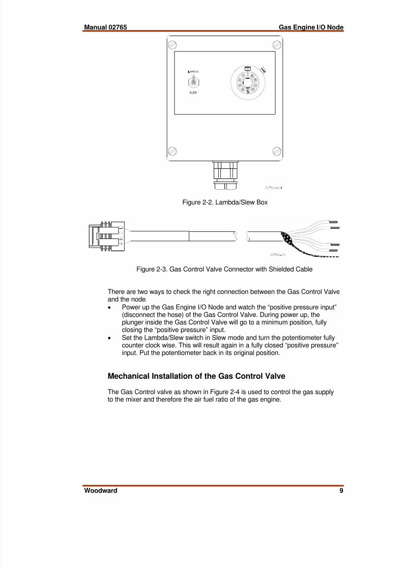
Figure 2-2. Lambda/Slew Box
Figure 2-3. Gas Control Valve Connector with Shielded Cable
There are two ways to check the right connection between the Gas Control Valve
and the node.• Power up the Gas Engine I/O Node and watch the “positive pressure input”
(disconnect the hose) of the Gas Control Valve. During power up, theplunger inside the Gas Control Valve will go to a minimum position, fullyclosing the “positive pressure” input.
• Set the Lambda/Slew switch in Slew mode and turn the potentiometer fullycounter clock wise. This will result again in a fully closed “positive pressure”input. Put the potentiometer back in its original position.
Mechanical Installation of the Gas Control Valve
The Gas Control valve as shown in Figure 2-4 is used to control the gas supply
to the mixer and therefore the air fuel ratio of the gas engine.

8/2/2019 02765_B
http://slidepdf.com/reader/full/02765b 16/38
Gas Engine I/O Node Manual 02765
10 Woodward
Figure 2-4. Gas Control Valve
The following points must be taken in account when mounting the Gas ControlValve on the engine:
• The output of the Gas Control Valve, marked with “TO REGULATOR”, mustbe connected to the sensing/impulse connection of the Zero PressureRegulator (ZPR).Therefore the ZPR must be equipped with an externalsensing/impulse connection.
•
The “POSITIVE PRESSURE” input signal of the Gas Control Valve must beconnected to the gas line between the ZPR and the Main Adjustment Screw(MAS).
• The “NEGATIVE PRESSURE” input signal of the Gas Control Valve mustbe connected to the gas line downstream of the MAS. This can be donedirectly after the MAS or to the prepared holes in the Deltec mixing unit onthe gas connection of the Deltec mixer. Especially when the air fuel ratiocontrol is used on landfill or bio-gas engines, the connection to the Deltecmixing unit points is advisable, to obtain a better response time.
• On V-engines with two mixing units an average negative pressure has to beconnected to the Gas Control Valve.
• When the special delivered hose is not used make sure, that the hose whichis used instead, has the same internal diameter. When the diameter is toosmall the response time is less and instability may occur.
• Due to the construction of the Gas Control Valve, the valve is not suitablefor mounting on the engine. Heavy and enduring vibrations will damage thevalve internally.
• The maximum allowable operating temperature is 80 °C.
• Avoid water inside the Gas Control Valve when the valve is used on landfillor bio-gas engines.
• H2S in bio-gas or landfill gas will damage the stepper motor internally.
Maintenance of the Gas Control Valve
The Gas Control Valve is the only moving part of the complete system that requires
maintenance. The Gas Control Valve needs to be cleaned and greased every 8000engine running hours for natural gas, and every 4000 hours for landfill or bio-gas.Use silicone spray to grease the moving parts in the Gas Control Valve.
Take care when disassembling the Gas Control Valve. Whenassembling and disassembling the stepper motor and the plunger,make sure NOT TO ROTATE the stepper motor or plunger. Rotatingone of those items will break down the flexible linkage between thestepper motor and the plunger. A broken flexible linkage will not bereplaced under warranty.

8/2/2019 02765_B
http://slidepdf.com/reader/full/02765b 17/38
Manual 02765 Gas Engine I/O Node
Woodward 11
Lambda Sensor Input (Terminals 15/16)
General Information
The Universal Exhaust Gas Oxygen (UEGO) sensor operates with a controllerwhich controls the temperature of the sensor and converts the sensor pumpingcurrent into an analogue signal from 2.5 Vdc to 4.5 Vdc.
The complete UEGO sensor kit (see Figure 2-5) with part number 1680-447consists of:
• the UEGO sensor• the UEGO controller
• the wiring harness
Figure 2-5. UEGO Sensor Kit
The UEGO sensor is used as a feedback signal for the closed loop air fuel ratiocontrol. The application software uses this signal to trim the Gas Control Valve inorder to run the gas engine on the right lambda.

8/2/2019 02765_B
http://slidepdf.com/reader/full/02765b 18/38
Gas Engine I/O Node Manual 02765
12 Woodward
Electrical Installation of the UEGO Sensor
Use shielded twisted-pair wires to connect the lambda signal to terminals 15 &16. For connection between the UEGO sensor and the controller use the originalwiring harness. The four wires from UEGO wiring harness must be connected tothe Gas Engine I/O Node as follows:
UEGO Gas Engine I/O Node
Black lambda sensor (–) terminal 15Green lambda sensor (+) terminal 16Yellow lambda sensor supply (–) terminal 17Orange lambda sensor supply (+) terminal 18
A shield connection is provided at terminal 14.
Mechanical Installation of the UEGO Sensor
1. Mount the sensor close to the engine to increase the response time of theUEGO sensor.
2. Mount the sensor in a horizontal position to use the air flow around theengine for cooling the outer side of the sensor.
3. Do not mount the sensor at the top or at the bottom of the exhaust pipe.
4. ALWAYS use a heat shield around the sensor to prevent the sensor housingfrom heating up by radiation (see Figure 2-6).
Figure 2-6. Thermal Characteristics of the UEGO Sensor
5. Measure the sensor housing temperatures at full load to be sure that themaximum temperatures are not reached.

8/2/2019 02765_B
http://slidepdf.com/reader/full/02765b 19/38
Manual 02765 Gas Engine I/O Node
Woodward 13
6. Always use the special protection cover and welding ring for mounting thesensor (see Figure 2-7).
Figure 2-7. UEGO Sensor
For mounting the protection cover into the welding ring and theUEGO sensor into the protection cover, always use Loctite NickelAnti-Seize (Cat Number 76777). See Figure 2-8.
Figure 2-8. Mounting of the UEGO Sensor in the Exhaust Pipe

8/2/2019 02765_B
http://slidepdf.com/reader/full/02765b 20/38
Gas Engine I/O Node Manual 02765
14 Woodward
7. The sensor should never be mounted in the exhaust pipe when the GasEngine I/O Node is powered down. The sensor is not heated then.
Running the engine with an unheated sensor will damage the sensor.Remove the UEGO sensor if not used. The hole can be plugged offwith an old spark plug (thread M18 x 1.5).
8. Before running the engine, the Gas Engine I/O Node should be powered upand the UEGO controller should be switched on at least 10 minutes prior tostarting the engine
Calibration of the UEGO Sensor
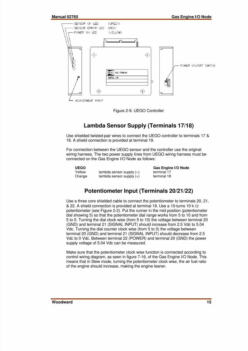
If the power on/off switch is turned on, the yellow power on LED will start to flash,this means that the power supply of the controller is functioning correctly. Thecontroller starts immediately with its warm up cycle. After 30 seconds the redsensor error LED turns off, at the same time the green sensor OK LED turns on.
If the red sensor error LED is burning during operation then the sensor is
misreading the right lambda value. This can be caused by overheating thesensor.
The UEGO controllers normally have about the same output voltages. The outputat lambda = 1.00 shall always be around 3.00 Vdc. At a lambda = ±1.55 (this isapproximately 8.5% O2 with natural gas) the output voltage should be between3.49 and 3.54 Vdc.
Lambda sensors are more or less sensitive to aging, which means that the outputvoltage may drift a little over a certain time period. Therefore the output voltageneeds to be checked every service interval of the engine. The followingprocedure can be used:
• Stop the engine.
• Turn off the power of the controller using the power on/off switch (see Figure2-9).
• Dismount the UEGO sensor from the exhaust and let it hang free in theopen air.
• Turn on the power of the controller and let the sensor clean itself with freshair during the service interval.
• Before mounting the sensor back to the exhaust, make sure you check theoutput voltage with a multimeter.
• The output voltage should be exactly 4.50 Vdc at 20.9% oxygen.
• If necessary, trim the adjustment point (see Figure 2-9) so that themultimeter is reading exactly 4.50 Vdc
• Remount the UEGO sensor back in the exhaust.
8/2/2019 02765_B
http://slidepdf.com/reader/full/02765b 21/38
Manual 02765 Gas Engine I/O Node
Woodward 15
Figure 2-9. UEGO Controller
Lambda Sensor Supply (Terminals 17/18)
Use shielded twisted-pair wires to connect the UEGO controller to terminals 17 &18. A shield connection is provided at terminal 19.
For connection between the UEGO sensor and the controller use the originalwiring harness. The two power supply lines from UEGO wiring harness must beconnected on the Gas Engine I/O Node as follows:
UEGO Gas Engine I/O NodeYellow lambda sensor supply (–) terminal 17Orange lambda sensor supply (+) terminal 18
Potentiometer Input (Terminals 20/21/22)
Use a three core shielded cable to connect the potentiometer to terminals 20, 21,
& 22. A shield connection is provided at terminal 19. Use a 10-turns 10 kΩ potentiometer (see Figure 2-2). Put the runner in the mid position (potentiometerdial showing 5) so that the potentiometer dial range works from 5 to 10 and from5 to 0. Turning the dial clock wise (from 5 to 10) the voltage between terminal 20(GND) and terminal 21 (SIGNAL INPUT) should increase from 2.5 Vdc to 5.04Vdc. Turning the dial counter clock wise (from 5 to 0) the voltage betweenterminal 20 (GND) and terminal 21 (SIGNAL INPUT) should decrease from 2.5Vdc to 0 Vdc. Between terminal 22 (POWER) and terminal 20 (GND) the powersupply voltage of 5.04 Vdc can be measured.
Make sure that the potentiometer clock wise function is connected according tocontrol wiring diagram, as seen in figure 7-16, of the Gas Engine I/O Node. Thismeans that in Slew mode, turning the potentiometer clock wise, the air fuel ratioof the engine should increase, making the engine leaner.
8/2/2019 02765_B
http://slidepdf.com/reader/full/02765b 22/38
Gas Engine I/O Node Manual 02765
16 Woodward
The potentiometer works in conjunction with the Lambda/Slew switch. In Lambdamode the potentiometer can be used for increasing or decreasing the lambdareference of the application software making the engine run leaner or richer. Inslew mode the potentiometer can be used to for moving the plunger manually inthe Gas Control Valve for the set up of the air fuel ratio application software.
MAP Sensor Input (Terminals 24/25/26)
Electrical Installation of the MAP Sensor
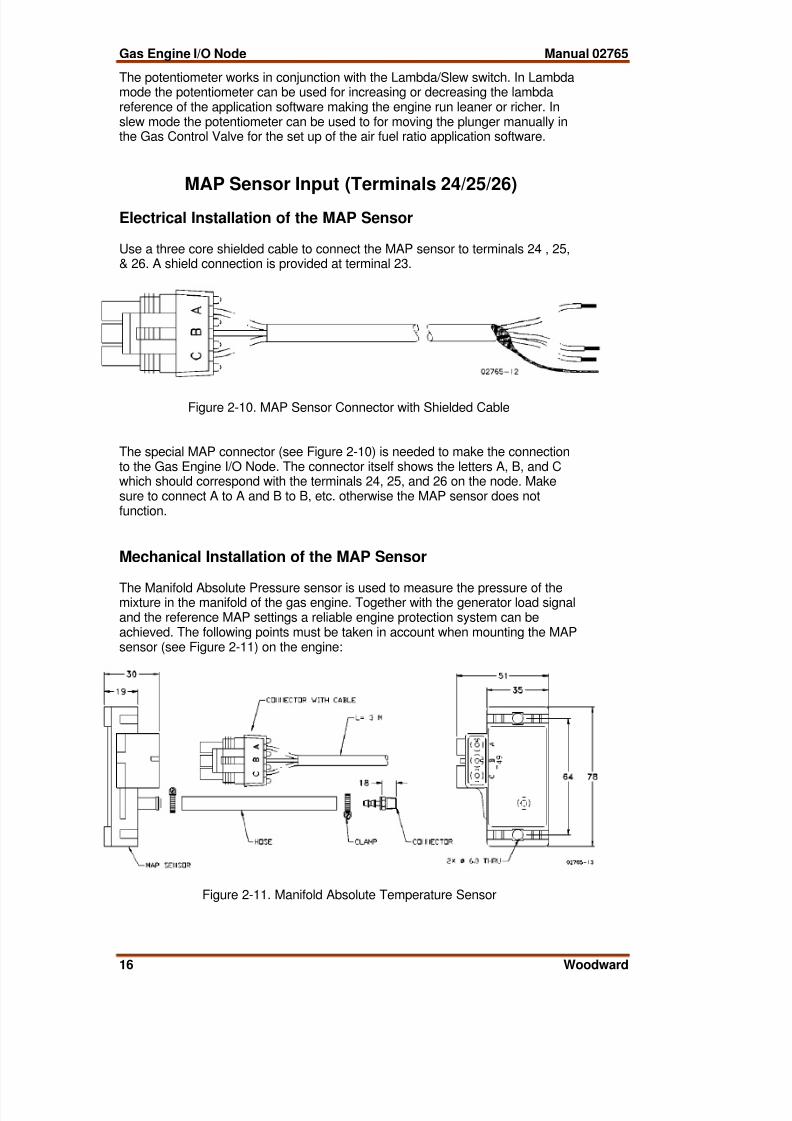
Use a three core shielded cable to connect the MAP sensor to terminals 24 , 25,& 26. A shield connection is provided at terminal 23.
Figure 2-10. MAP Sensor Connector with Shielded Cable
The special MAP connector (see Figure 2-10) is needed to make the connectionto the Gas Engine I/O Node. The connector itself shows the letters A, B, and Cwhich should correspond with the terminals 24, 25, and 26 on the node. Makesure to connect A to A and B to B, etc. otherwise the MAP sensor does notfunction.
Mechanical Installation of the MAP Sensor
The Manifold Absolute Pressure sensor is used to measure the pressure of themixture in the manifold of the gas engine. Together with the generator load signaland the reference MAP settings a reliable engine protection system can beachieved. The following points must be taken in account when mounting the MAPsensor (see Figure 2-11) on the engine:
Figure 2-11. Manifold Absolute Temperature Sensor

8/2/2019 02765_B
http://slidepdf.com/reader/full/02765b 23/38
Manual 02765 Gas Engine I/O Node
Woodward 17
• The MAP sensor must be connected to the intake manifold, downstream thethrottle valve and aftercooler.
• The MAP sensor can be mounted directly on the engine using two M6 bolts.The maximum allowable operating temperature is 80 ºC.
• Use the special rubber hose and hose connectors which are part of the MAPsensor kit
• On stationary engines the maximum length of the MAP hose is not veryimportant, however for a reasonably quick response time of the sensor,
• a maximum length of one meter is preferred.• The MAP cable is not high temperature resistance, physical contact with
high temperature parts of the engine is not allowed and can damage thecable.
MAP Sensor Checkout Procedure
The following checkout procedure can be used to see if the MAP sensor itself isfunctioning properly:
Measure the voltage between the signal wire (B) and the sensor common wire
(A), using a multimeter. At an ambient pressure of ±100 kPa, the multimeter
should read a voltage depending on the pressure range of the MAP sensor.
The following voltages can be seen:pressure range part number signal out0-100 kPa P/N 1680-439 4.559 Vdc0-200 kPa P/N 1680-441 2.398 Vdc0-300 kPa P/N 1680-443 1.625 Vdc
MAT Sensor Input (Terminals 28/29/30)
Electrical Installation of the MAT Sensor
Use a three core shielded cable to connect the MAT sensor to terminals 28 , 29,& 30. A shield connection is provided at terminal 27. The MAT sensor is aResistance Temperature Device, a PT100 type of RTD sensor. The RTD sensorprovides one connection to one end and two to the other end of the sensor.Connected to the terminals 28, 29, & 30, designed to accept three wire input,compensation is achieved for lead resistance and temperature change in leadresistance. See figure 4-12 for the MAT connection on the node.
Figure 2-12. MAT Connection on the Terminals

8/2/2019 02765_B
http://slidepdf.com/reader/full/02765b 24/38
Gas Engine I/O Node Manual 02765
18 Woodward
Mechanical Installation of the MAT Sensor
The Manifold Absolute Temperature sensor is used to measure the temperatureof the mixture in the manifold of the gas engine. The MAT signal is needed tocorrect the lambda reference value of the air fuel ratio control, to keep the NO x level constant.
Figure 2-13. Manifold Absolute Temperature Sensor
The following points must be taken in account when mounting the MAT sensor(see Figure 2-13) on the engine:• The MAT sensor must be mounted on the intake manifold, downstream the
throttle valve where the average temperature of the mixture, can bemeasured.
• The MAT sensor tip must be located in the middle of the mixture flow,otherwise the temperature measurement is less accurate, due to theinfluence radiation of the manifold.
• Use the special supplied MAT nipple for connection.
• The MAT sensor cable is high temperature resistant up to 100 ºC.
MAT Sensor Checkout Procedure
The following checkout procedure can be used to see if the MAT sensor itself isfunctioning properly:
Measure the resistance between the brown and the black wire, using amultimeter. At 0 °C, the resistance between the brown and the black wire should
be exactly 100 Ω.
Example: at 20 °C, the resistance is 107.79 Ω.
RTD #2 or Analog Input #2 (Terminals 32/33/34)Use a two or three conductor shielded wire depending on the configuration of thisinput A shield connection is provided at terminal 31 for both configurations. Thedefault jumper setting of this input is set for a RTD sensor. This input can beused to connect an Air Temperature Sensor to the node if this is required by theapplication. The same requirements as for a MAT sensor are applied if a PT100type of sensor is being used for air temperature measurement. In case of ananalog input, see Chapter 2 for the right jumper setting of this input.

8/2/2019 02765_B
http://slidepdf.com/reader/full/02765b 25/38
Manual 02765 Gas Engine I/O Node
Woodward 19
RTD #1 or Analog Input #1 (Terminals 36/37/38)
Use a two or three conductor shielded wire depending on the configuration of thisinput. A shield connection is provided at terminal 35 for both configurations. Thedefault jumper setting of this input is set for a RTD sensor. This input can beused to connect a Gas Temperature Sensor to the node if this is required by theapplication. The same requirements as for a MAT sensor are applied if a PT100type of sensor is being used for gas temperature measurement. In case ofan analogue input see Chapter 2 for the right jumper setting of this input.
LON Communication Channel (Terminals 40/41/42)
The communications network used by the Gas Engine I/O Node is Echelon® Corporation’s LonWorks® technology. An Echelon Neuron® chip operates as aslave processor to the 723 control main processor. LonWorks provides theinterconnection between all controls over which I/O (input/output) informationpasses (see Figure 2-14). There is no polarity for the LON wiring and the shieldconnection is available at terminal 39.
Figure 2-14. Typical LON Setup
The cable used for the network will affect the overall system performance withrespect to distance, stub length. and total number of nodes supported on a singlechannel. Echelon recommends the use of UL Level IV, 0.325 mm² (22 AWG)twisted pair cable for the network bus as defined in UL’s LAN Cable CertificationProgram, UL document number 200-120 20 M/11/91.
Proper LonWorks network wiring is critical to assure that the network (and thusthe air fuel ratio control system) operates correctly. Figure 2-14 illustrates atypical system with a Gas Engine I/O Node. The system may include otherLonWorks-compatible devices, such as a Woodward DSLC™, DigitalSynchronizer and Load Control. The following requirements must be met:
1. Use only recommended shielded twisted pair cabling for the LonWorksnetwork. Correct cable is available from Woodward, Belden, or othersuppliers providing an equivalent cable.
Woodward part number 2008-349

8/2/2019 02765_B
http://slidepdf.com/reader/full/02765b 26/38
Gas Engine I/O Node Manual 02765
20 Woodward
BeldenPO Box 1980Richmond, IN 47375(317) 983-5200
Belden part numberP/N Description9207 PVC 0.52 mm² (20 AWG) shielded. NC Type CL2, CSA Cert. PCC FT 1
89207 Teflon 0.52 mm² (20 AWG) shielded, Plenum version. NECType CMP, CSA Cert. FT 4YR28867 PVC 0.325 mm² (22 AWG) shielded.YQ28863 Plenum 0.325 mm² (22 AWG) shielded.
2. Maximum cable length for a LonWorks 1.25 MBEs network is 500 m (1640ft).
3. Stubs, or wiring drops, connecting intermediate devices to the main cableare limited to 300 mm in length.
4. Shields must be carried through all breakout boxes to provide a continuousshield throughout the network.
5. The network must be properly terminated at each end of the cable. Internalcomponents are provided in all Woodward 723 DCS, Gas Engine I/O Nodeor DSLC which provide proper network termination with installation of a
jumper on the controls at each end of the cable. Intermediate nodes shouldnot have the termination jumper installed.
Figure 2-15. Location of the Network LEDs and ID Switch
A special Serial LonTalk Adapter (SLTA) is needed to make a network “binding”between the Gas Engine I/O Node and the 723 DCS.
An SLTA is a network interface that enables any PC to connect to a LonWorksnetwork. An SLTA enables the attached PC to act as an application node on aLonWorks network. When used with a PC and the LonManager LonMakerInstallation Tool, the SLTA can also be used to build sophisticated networkmanagement, monitoring and control tools for the LonWorks network.

8/2/2019 02765_B
http://slidepdf.com/reader/full/02765b 27/38
Manual 02765 Gas Engine I/O Node
Woodward 21
The red service LED, as seen in Figure 2-15, will reflect the network status of theGas Engine I/O Node:
• blinking means Gas Engine I/O Node is unconfigured
• off means Gas Engine I/O Node is configured• on means Gas Engine I/O Node is applicationless
The green status LED, as seen in Figure 2-15, can be used to check with theLonManager LonMaker Installation Tool if the network is functioning correctly.
With the LonManager LonMaker Installation Tool a “wink” command can betransmitted via the network. After receiving the “wink” command the green LEDwill start to blink. It stops after 15 minutes, or when it receives a second “wink”command.
The identification push-button switch (ID switch), as seen in figure 4-15, must beused during installation to broadcast the unique 48-bit Neuron ID on the network.

8/2/2019 02765_B
http://slidepdf.com/reader/full/02765b 28/38
Gas Engine I/O Node Manual 02765
22 Woodward
Chapter 3.Service Options
Product Service Options
If you are experiencing problems with the installation, or unsatisfactoryperformance of a Woodward product, the following options are available:
• Consult the troubleshooting guide in the manual.• Contact the manufacturer or packager of your system.• Contact the Woodward Full Service Distributor serving your area.
• Contact Woodward technical assistance (see “How to Contact Woodward”later in this chapter) and discuss your problem. In many cases, your problemcan be resolved over the phone. If not, you can select which course of actionto pursue based on the available services listed in this chapter.
OEM and Packager Support: Many Woodward controls and control devices areinstalled into the equipment system and programmed by an Original EquipmentManufacturer (OEM) or Equipment Packager at their factory. In some cases, the
programming is password-protected by the OEM or packager, and they are the bestsource for product service and support. Warranty service for Woodward productsshipped with an equipment system should also be handled through the OEM orPackager. Please review your equipment system documentation for details.
Woodward Business Partner Support: Woodward works with and supports aglobal network of independent business partners whose mission is to serve theusers of Woodward controls, as described here:
• A Full Service Distributor has the primary responsibility for sales, service,system integration solutions, technical desk support, and aftermarketmarketing of standard Woodward products within a specific geographic areaand market segment.
• An Authorized Independent Service Facility (AISF) provides authorizedservice that includes repairs, repair parts, and warranty service on Woodward'sbehalf. Service (not new unit sales) is an AISF's primary mission.
• A Recognized Engine Retrofitter (RER) is an independent company thatdoes retrofits and upgrades on reciprocating gas engines and dual-fuelconversions, and can provide the full line of Woodward systems andcomponents for the retrofits and overhauls, emission compliance upgrades,long term service contracts, emergency repairs, etc.
• A Recognized Turbine Retrofitter (RTR) is an independent company thatdoes both steam and gas turbine control retrofits and upgrades globally, andcan provide the full line of Woodward systems and components for theretrofits and overhauls, long term service contracts, emergency repairs, etc.
A current list of Woodward Business Partners is available at
www.woodward.com/support .

8/2/2019 02765_B
http://slidepdf.com/reader/full/02765b 29/38
Manual 02765 Gas Engine I/O Node
Woodward 23
Woodward Factory Servicing Options
The following factory options for servicing Woodward products are availablethrough your local Full-Service Distributor or the OEM or Packager of theequipment system, based on the standard Woodward Product and ServiceWarranty (5-01-1205) that is in effect at the time the product is originally shippedfrom Woodward or a service is performed:• Replacement/Exchange (24-hour service)• Flat Rate Repair
• Flat Rate Remanufacture
Replacement/Exchange: Replacement/Exchange is a premium programdesigned for the user who is in need of immediate service. It allows you torequest and receive a like-new replacement unit in minimum time (usually within24 hours of the request), providing a suitable unit is available at the time of therequest, thereby minimizing costly downtime. This is a flat-rate program andincludes the full standard Woodward product warranty (Woodward Product andService Warranty 5-01-1205).
This option allows you to call your Full-Service Distributor in the event of anunexpected outage, or in advance of a scheduled outage, to request a
replacement control unit. If the unit is available at the time of the call, it canusually be shipped out within 24 hours. You replace your field control unit withthe like-new replacement and return the field unit to the Full-Service Distributor.
Charges for the Replacement/Exchange service are based on a flat rate plusshipping expenses. You are invoiced the flat rate replacement/exchange chargeplus a core charge at the time the replacement unit is shipped. If the core (fieldunit) is returned within 60 days, a credit for the core charge will be issued.
Flat Rate Repair: Flat Rate Repair is available for the majority of standardproducts in the field. This program offers you repair service for your products withthe advantage of knowing in advance what the cost will be. All repair work carriesthe standard Woodward service warranty (Woodward Product and Service
Warranty 5-01-1205) on replaced parts and labor.
Flat Rate Remanufacture: Flat Rate Remanufacture is very similar to the FlatRate Repair option with the exception that the unit will be returned to you in “like-new” condition and carry with it the full standard Woodward product warranty(Woodward Product and Service Warranty 5-01-1205). This option is applicableto mechanical products only.

8/2/2019 02765_B
http://slidepdf.com/reader/full/02765b 30/38
Gas Engine I/O Node Manual 02765
24 Woodward
Returning Equipment for Repair
If a control (or any part of an electronic control) is to be returned for repair,please contact your Full-Service Distributor in advance to obtain ReturnAuthorization and shipping instructions.
When shipping the item(s), attach a tag with the following information:• return number;• name and location where the control is installed;
• name and phone number of contact person;• complete Woodward part number(s) and serial number(s);
• description of the problem;
• instructions describing the desired type of repair.
Packing a Control
Use the following materials when returning a complete control:• protective caps on any connectors;• antistatic protective bags on all electronic modules;
• packing materials that will not damage the surface of the unit;• at least 100 mm (4 inches) of tightly packed, industry-approved packing
material;
• a packing carton with double walls;
• a strong tape around the outside of the carton for increased strength.
To prevent damage to electronic components caused by improperhandling, read and observe the precautions in Woodward manual82715, Guide for Handling and Protection of Electronic Controls,Printed Circuit Boards, and Modules .
Replacement Parts
When ordering replacement parts for controls, include the following information:• the part number(s) (XXXX-XXXX) that is on the enclosure nameplate;• the unit serial number, which is also on the nameplate.

8/2/2019 02765_B
http://slidepdf.com/reader/full/02765b 31/38
Manual 02765 Gas Engine I/O Node
Woodward 25
Engineering Services
Woodward offers various Engineering Services for our products. For these services,you can contact us by telephone, by email, or through the Woodward website.• Technical Support
• Product Training
• Field Service
Technical Support is available from your equipment system supplier, your local Full-Service Distributor, or from many of Woodward’s worldwide locations, dependingupon the product and application. This service can assist you with technicalquestions or problem solving during the normal business hours of the Woodwardlocation you contact. Emergency assistance is also available during non-businesshours by phoning Woodward and stating the urgency of your problem.
Product Training is available as standard classes at many of our worldwidelocations. We also offer customized classes, which can be tailored to your needsand can be held at one of our locations or at your site. This training, conductedby experienced personnel, will assure that you will be able to maintain systemreliability and availability.
Field Service engineering on-site support is available, depending on the productand location, from many of our worldwide locations or from one of our Full-Service Distributors. The field engineers are experienced both on Woodwardproducts as well as on much of the non-Woodward equipment with which ourproducts interface.
For information on these services, please contact us via telephone, email us, or
use our website and reference www.woodward.com/support , and then
Customer Support .
How to Contact Woodward
For assistance, call one of the following Woodward facilities to obtain the addressand phone number of the facility nearest your location where you will be able toget information and service.
Electrical Power SystemsFacility --------------- Phone NumberAustralia ----------- +61 (2) 9758 2322Brazil ------------- +55 (19) 3708 4800China ------------ +86 (512) 6762 6727Germany:
Kempen --- +49 (0) 21 52 14 51Stuttgart ----- +49 (711) 78954-0
India --------------- +91 (129) 4097100Japan -------------- +81 (43) 213-2191Korea--------------- +82 (51) 636-7080
Poland -------------- +48 12 618 92 00United States----- +1 (970) 482-5811
Engine SystemsFacility --------------- Phone NumberAustralia ----------- +61 (2) 9758 2322Brazil ------------- +55 (19) 3708 4800China ------------ +86 (512) 6762 6727Germany:
Stuttgart ----- +49 (711) 78954-0India --------------- +91 (129) 4097100Japan -------------- +81 (43) 213-2191Korea--------------- +82 (51) 636-7080The Netherlands - +31 (23) 5661111
United States----- +1 (970) 482-5811
Turbine SystemsFacility --------------- Phone NumbAustralia ----------- +61 (2) 9758 232Brazil ------------- +55 (19) 3708 480China ------------ +86 (512) 6762 672
India --------------- +91 (129) 409710Japan -------------- +81 (43) 213-219Korea--------------- +82 (51) 636-708The Netherlands - +31 (23) 56611
United States----- +1 (970) 482-58
You can also contact the Woodward Customer Service Department or consult our
worldwide directory on Woodward’s website (www.woodward.com/support)for the name of your nearest Woodward distributor or service facility.
For the most current product support and contact information, please refer to the
latest version of publication 51337 at www.woodward.com/publications .
8/2/2019 02765_B
http://slidepdf.com/reader/full/02765b 32/38
Gas Engine I/O Node Manual 02765
26 Woodward
Technical Assistance
If you need to telephone for technical assistance, you will need to provide the following information.Please write it down here before phoning:
GeneralYour Name
Site LocationPhone NumberFax Number
Prime Mover InformationEngine/Turbine Model NumberManufacturerNumber of Cylinders (if applicable)Type of Fuel (gas, gaseous, steam, etc)RatingApplication
Control/Governor InformationPlease list all Woodward governors, actuators, and electronic controls in your system:
Woodward Part Number and Revision Letter
Control Description or Governor Type
Serial Number
Woodward Part Number and Revision Letter
Control Description or Governor Type
Serial Number
Woodward Part Number and Revision Letter
Control Description or Governor Type
Serial Number
If you have an electronic or programmable control, please have the adjustment setting positions or
the menu settings written down and with you at the time of the call.

8/2/2019 02765_B
http://slidepdf.com/reader/full/02765b 33/38
Manual 02765 Gas Engine I/O Node
Woodward 27
Appendix A.Part Number List
Description Woodward Part Number
SensorMAP 0-1 bar absolute 1680-439MAP 0-2 bar absolute 1680-441MAP 0-3 bar absolute 1680-443
Oxygen “Lambda” sensor 1680-445UEGO sensor kit 1680-447
MAT PT100 sensor 1680-449Air Temperature PT100 sensor 1680-449
Gas Temperature PT100 sensor 1680-449
ValveGas Control Valve 1314-023
Potentiometer
10-turns 10 kΩ Potentiometer 1657-659Dial 15-turns 1659-609

8/2/2019 02765_B
http://slidepdf.com/reader/full/02765b 34/38
Gas Engine I/O Node Manual 02765
28 Woodward
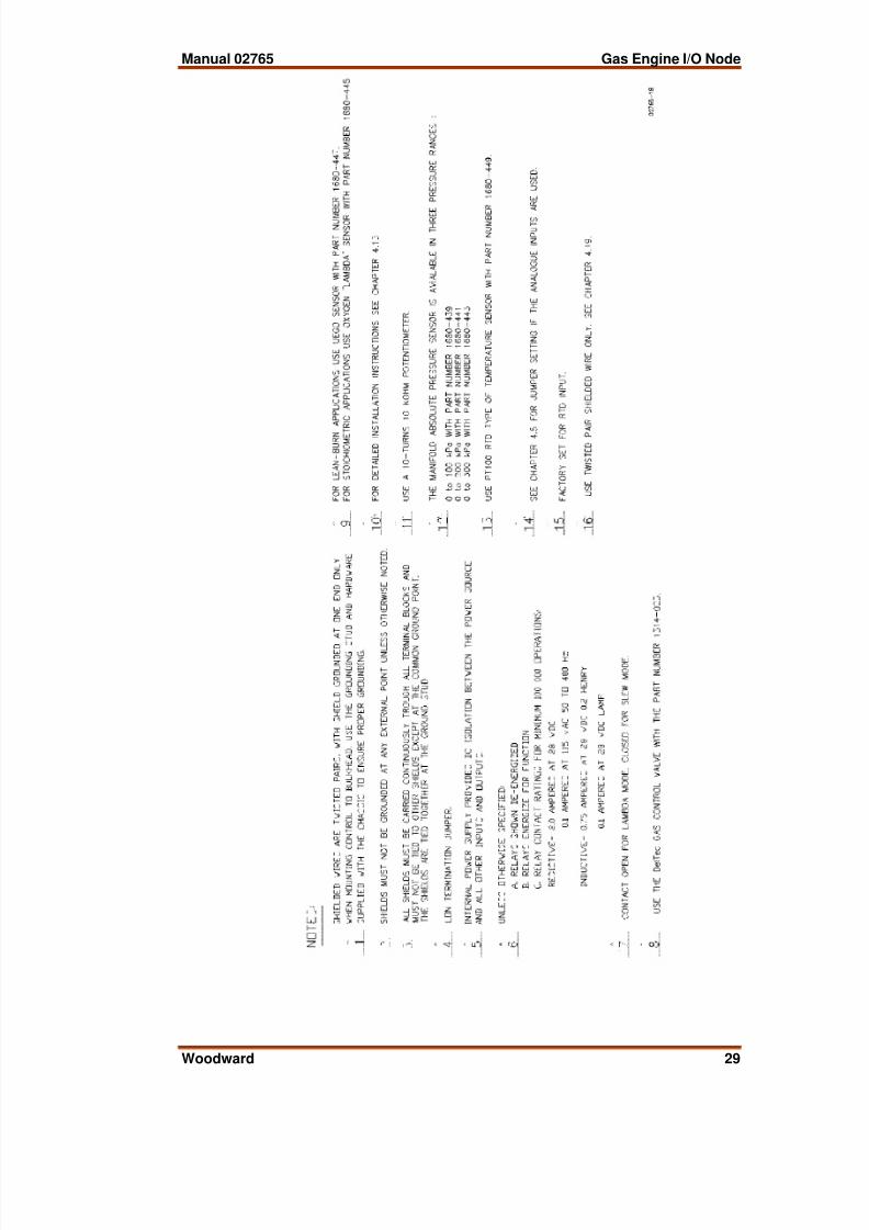
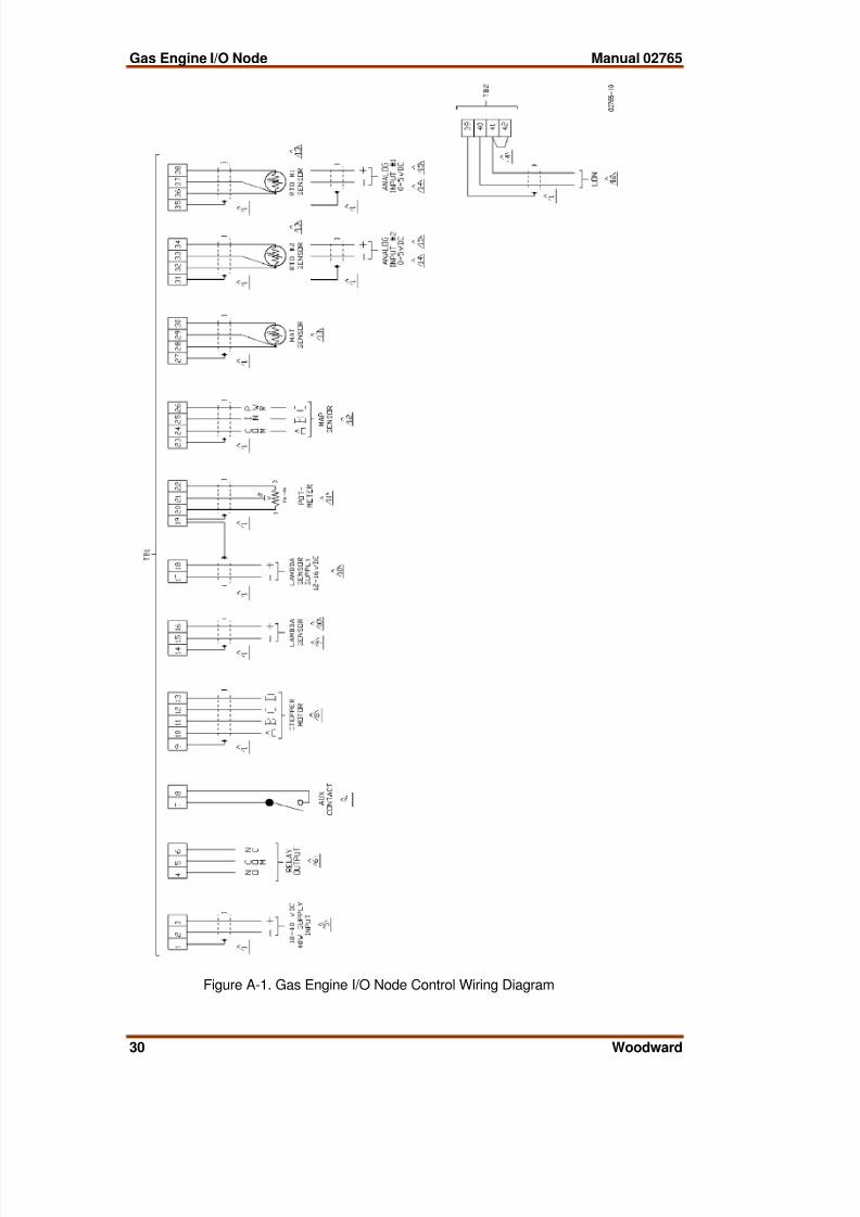
Appendix B.Control Wiring Diagram
Control wiring is shown on the next two pages.
8/2/2019 02765_B
http://slidepdf.com/reader/full/02765b 35/38
8/2/2019 02765_B
http://slidepdf.com/reader/full/02765b 36/38
Gas Engine I/O Node Manual 02765
30 Woodward
Figure A-1. Gas Engine I/O Node Control Wiring Diagram

8/2/2019 02765_B
http://slidepdf.com/reader/full/02765b 37/38
Manual 02765 Gas Engine I/O Node
Woodward 31
Appendix C.Gas Engine I/O Node Specification
Woodward Part Number: 9906-129, Gas Engine I/O Node
Power Supply Rating 18–40 Vdc (24 or 32 Vdc nominal)Power Consumption 40 W nominal
Test Spec LevelVibration US MIL-STD-810C, Method 514.2, Procedure 8 Curve WShock US MIL-STD-810C, Method 516.2, Procedure 1 40 g, 11 ms
Terminal-peakSawtooth Pulse
Storage TemperatureUS MIL-STD-810D, Method 501.2, Procedure 1 105 °CUS MIL-STD-810D, Method 502.2, Procedure 1 –50 °C
Operating TemperatureUS MIL-STD-810D, Method 501.2, Procedure 2 70 °CUS MIL-STD-810D, Method 502.2, Procedure 2 –40 °C
Humidity US MIL-STD-810D, Method 507.2, Procedure 3Salt Fog US MIL-STD-810D, Method 509.2, Procedure 1Enclosure IEC 529 IP56CE EMC Emissions
EN50081-2CE EMC Immunity
EN50082-2

8/2/2019 02765_B
http://slidepdf.com/reader/full/02765b 38/38
We appreciate your comments about the content of our publications.
Send comments to: [email protected]
Please reference publication 02765A.
PO Box 1519, Fort Collins CO 80522-1519, USA1000 East Drake Road, Fort Collins CO 80525, USA
Phone +1 (970) 482-5811 • Fax +1 (970) 498-3058
Email and Website—www.woodward.com
Woodward has company-owned plants, subsidiaries, and branches,as well as authorized distributors and other authorized service and sales facilities throughout the world.


