021 AIRFRAMES & SYSTEMS, ELECTRICS, … 021 022 AGK IR_A (prior to NPA-FCL 25).pdf021 AIRFRAMES &...
40
021 AIRFRAMES & SYSTEMS, ELECTRICS, POWERPLANT, EMERGENCY EQUIPMENT
-
Upload
truongkhue -
Category
Documents
-
view
267 -
download
2
Transcript of 021 AIRFRAMES & SYSTEMS, ELECTRICS, … 021 022 AGK IR_A (prior to NPA-FCL 25).pdf021 AIRFRAMES &...
021
AIRFRAMES & SYSTEMS,
ELECTRICS, POWERPLANT,
EMERGENCY EQUIPMENT
INSTRUMENT RATING (A) (AIRCRAFT GENERAL KNOWLEDGE)
Issue 1: Feb 2003 021-ASEPE-2 CJAA Licensing Division
JAR-FCL REF NO
LEARNING OBJECTIVES REMARKS
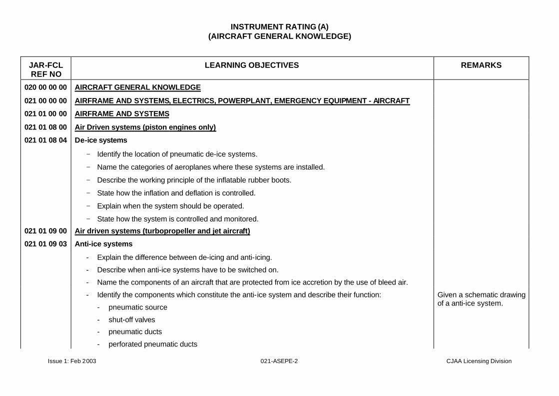
020 00 00 00 AIRCRAFT GENERAL KNOWLEDGE 021 00 00 00 AIRFRAME AND SYSTEMS, ELECTRICS, POWERPLANT, EMERGENCY EQUIPMENT - AIRCRAFT 021 01 00 00 AIRFRAME AND SYSTEMS 021 01 08 00 Air Driven systems (piston engines only) 021 01 08 04 De-ice systems
− Identify the location of pneumatic de-ice systems.
− Name the categories of aeroplanes where these systems are installed.
− Describe the working principle of the inflatable rubber boots.
− State how the inflation and deflation is controlled.
− Explain when the system should be operated.
− State how the system is controlled and monitored.
021 01 09 00 Air driven systems (turbopropeller and jet aircraft) 021 01 09 03 Anti-ice systems
- Explain the difference between de-icing and anti-icing.
- Describe when anti-ice systems have to be switched on.
- Name the components of an aircraft that are protected from ice accretion by the use of bleed air.
- Identify the components which constitute the anti-ice system and describe their function:
- pneumatic source
- shut-off valves
- pneumatic ducts
- perforated pneumatic ducts
Given a schematic drawing of a anti-ice system.
INSTRUMENT RATING (A) (AIRCRAFT GENERAL KNOWLEDGE)
Issue 1: Feb 2003 021-ASEPE-3 CJAA Licensing Division
JAR-FCL REF NO
LEARNING OBJECTIVES REMARKS
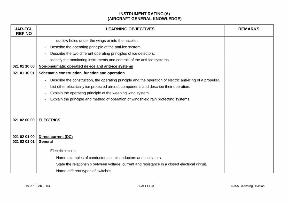
- outflow holes under the wings or into the nacelles
- Describe the operating principle of the anti-ice system.
- Describe the two different operating principles of ice detectors.
- Identify the monitoring instruments and controls of the anti-ice systems. 021 01 10 00 Non-pneumatic operated de-ice and anti-ice systems 021 01 10 01 Schematic construction, function and operation
- Describe the construction, the operating principle and the operation of electric anti-icing of a propeller.
- List other electrically ice protected aircraft components and describe their operation.
- Explain the operating principle of the weeping wing system.
- Explain the principle and method of operation of windshield rain protecting systems.
021 02 00 00 ELECTRICS
021 02 01 00 Direct current (DC) 021 02 01 01 General
− Electric circuits − Name examples of conductors, semiconductors and insulators.
− State the relationship between voltage, current and resistance in a closed electrical circuit.
− Name different types of switches.
INSTRUMENT RATING (A) (AIRCRAFT GENERAL KNOWLEDGE)
Issue 1: Feb 2003 021-ASEPE-4 CJAA Licensing Division
JAR-FCL REF NO
LEARNING OBJECTIVES REMARKS
− State the purpose of the guard cap in the case of toggle switches.
− State how the following devices work: thermo-, bimetallic-, time- and proximity-switches.
− Voltage, current, resistance − Define voltage in words and state the relevant unit of measurement.
− Define current in words and state the relevant unit of measurement.
− Ohm’s law − State Ohm’s Law in qualitative terms.
− Calculate voltage, current and resistance using Ohm’s Law.
− Resistive circuits
− Calculate the total value of resistance in series and parallel circuits
− Explain the relationship between individual voltages and current when resistors are connected in series.
− Explain the relationship between individual currents and voltage when resistors are connected in parallel.
− Resistance as a function of temperature − Define the change of resistance of a material as a function of temperature
− State that resistances can have a positive temperature coefficient (PTC) or a negative temperature coefficient (NTC)
− State that PTC and NTC resistors are used in aircraft systems for temperature measurement
− Electrical power, electrical work − Define electrical power in qualitative terms and name the relevant unit of measurement
− Define electrical work in qualitative terms and name the relevant unit of measurement.
INSTRUMENT RATING (A) (AIRCRAFT GENERAL KNOWLEDGE)
Issue 1: Feb 2003 021-ASEPE-5 CJAA Licensing Division
JAR-FCL REF NO
LEARNING OBJECTIVES REMARKS
− Fuses, circuit breaker (function, type and operation) − Describe the method of operation of the circuit-breaker.
− Explain how a fuse is rated
− State the difference between a ”trip-free” and ”non-trip-free” circuit breaker.
− State the methods of detecting failures in fuses and circuit-breakers.
− List the different types of circuit breakers.
− The electrical field − Define the term ”electrical field” in qualitative terms
− State the difference between an electrical field and a magnetic field.
− The capacitor (function) − State the principle of construction of a capacitor.
− State how the capacitance (of a capacitor) is related to the plate area, the distance between the plates ,and the dielectric constant.
− State, in qualitative terms, the alteration in total capacitance of capacitors when connected in series or in parallel.
021 02 01 02 Batteries − Types, characteristics − State the components of a battery
− Name the types of rechargeable batteries used in aircraft
− For lead acid & NiCd batteries
− describe the processes which occur during charging and discharging
− differentiate between cell voltage and charging voltage
INSTRUMENT RATING (A) (AIRCRAFT GENERAL KNOWLEDGE)
Issue 1: Feb 2003 021-ASEPE-6 CJAA Licensing Division
JAR-FCL REF NO
LEARNING OBJECTIVES REMARKS
− state the effect of temperature.
− State the charging voltages which corresponds with different battery voltages.
− Compare lead-acid and NiCd batteries in respect of voltage, load behaviour, self-discharge, thermal runaway and storage life
− Capacity
− Define the term ”capacity of batteries”.
− State the relationship between voltage and capacity when batteries are connected in series or in parallel
− Uses − List the uses of lead acid batteries and NiCd batteries.
− Compare the relative advantages and disadvantages of lead acid and NiCd batteries
− Hazards
− State the dangers involved in overcharging lead-acid and NiCd batteries
− Indicate the behaviour of NiCd batteries in the case of too high a temperature (thermal runaway).
− Indicate why charging of lead-acid batteries with too high a voltage is dangerous
− State that NiCd batteries are monitored to avoid damages resultant from excessive temperature increase
021 02 01 03 Magnetism − Permanent magnetism
− State the properties of a magnet.
− Name the two poles of a permanent magnet
− List the ferromagnetic materials that can be used for permanent magnets
INSTRUMENT RATING (A) (AIRCRAFT GENERAL KNOWLEDGE)
Issue 1: Feb 2003 021-ASEPE-7 CJAA Licensing Division
JAR-FCL REF NO
LEARNING OBJECTIVES REMARKS
− State the direction of the magnetic flux outside the magnetic poles and inside the magnet
− Electromagnetism
− State that an electrical current produces a magnetic field around a conductor and define the direction of that field
− Indicate how the strength of the magnetic field changes if supported by a ferromagnetic core
− Explain the purpose of a relay
− Name the components of a relay
− Explain the purpose of a circuit breaker
− Name the components of a circuit breaker
− Explain how the coil circuit is insulated from the contact circuit
− Explain the difference between a normally-open, a normally-closed and a changeover contact in a relay.
− Electromagnetic power
− State how the inductance of a coil depends on the number of windings, the cross-sectional area of the coil the coil length and the magnetic conductivity.
− Electromagnetic induction
− Explain the principle of electromagnetic induction.
− State how the induced voltage in a coil depends on the number of windings, the magnetic flux and the rate of change of the magnetic flux
021 02 01 04 Generators − Alternator
− Principle, function and applications
INSTRUMENT RATING (A) (AIRCRAFT GENERAL KNOWLEDGE)
Issue 1: Feb 2003 021-ASEPE-8 CJAA Licensing Division
JAR-FCL REF NO
LEARNING OBJECTIVES REMARKS
− Describe the condition for a voltage to be induced in a conductor.
− Name the type of voltage which is induced in a rotating conductor loop in a homogeneous magnetic field
− Name the components of a simple generator.
− Define resonance.
− State in qualitative terms how voltage depends on number of turns, field strength, rpm and load
− Define the term ”internal-pole machine”.
− Name the components of an alternator.
− Compare the alternator and the simple generator with regard to:
voltage response at low rpm
power/weight ratio
brush sparking
current supply for the consumer
AC-DC conversion
− Describe the different generator switching possibilities in multiengine aircraft.
− With regard to load distribution, compare and contrast the split system with the parallel system.
− List the requirements to connect DC generators in parallel
− Explain how control of load sharing is achieved when two DC generators are operating in parallel
− Monitoring devices
− Name different monitoring devices
− Regulation, control and protection

INSTRUMENT RATING (A) (AIRCRAFT GENERAL KNOWLEDGE)
Issue 1: Feb 2003 021-ASEPE-9 CJAA Licensing Division
JAR-FCL REF NO
LEARNING OBJECTIVES REMARKS
− Explain the principle of voltage control.
− List the types of voltage regulators and explain their method of operation.
− Explain why reverse current flow from the battery to the generator must be prevented.
− Name the different types of reverse-current protection devices and explain how they work.
− Describe the different alternator designs
− Starter generator
− Describe how the starter generator is constructed and indicate its purpose.
021 02 01 05 Distribution
− Current distribution (buses)
− Explain the purpose of the bus
− Name the purpose of the battery bus and of the hot bus
− Name the components of the electrical power supply system used in flight
− State the number of ammeters in a multi generator system
− Use a block diagram to describe the supply system used in flight Given appropriate diagram
− Monitoring of electrical systems
− State the methods of monitoring of electrical systems
− Name the components of a moving-coil instrument
− Explain the function of a moving-coil instrument
− Explain the function of a Wheatstone Bridge
− Ammeter, voltmeter
− State the difference between a voltmeter and an ammeter with regard to resistance

INSTRUMENT RATING (A) (AIRCRAFT GENERAL KNOWLEDGE)
Issue 1: Feb 2003 021-ASEPE-10 CJAA Licensing Division
JAR-FCL REF NO
LEARNING OBJECTIVES REMARKS
− State the purpose of an ammeter and show how it is connected to the electrical load
− State the purpose of a voltmeter and show how it is connected to the electrical load
− Describe the possibilities for extending the measuring range of voltmeters and ammeters
− Interpret the different ammeter indications of the ammeter which monitors the charge current of the battery.
− Annunciators
− Identify different types of annunciators.
− Electrical consumers
− List types of electrical consumers (loads) for an aircraft, and their different purposes:
− lighting
− heating
− magnetic devices
− avionics systems
− instruments
− Describe the components of a DC motor
− Describe the circuitry for the field winding in the case of series, shunt, and compound wound motors.
− Describe the RPM and torque behaviour of a series-wound motor and a shunt-wound motor as the load increases/decreases.
− Explain how the direction of rotation of a DC motor can be changed.
− Name typical applications for series and shunt field motor.
− DC power distribution:
INSTRUMENT RATING (A) (AIRCRAFT GENERAL KNOWLEDGE)
Issue 1: Feb 2003 021-ASEPE-11 CJAA Licensing Division
JAR-FCL REF NO
LEARNING OBJECTIVES REMARKS
− Construction, operation and system monitoring
− Using simplified schematics, explain the construction of single- and multi-engined DC flight equipment
− Using simplified schematics, show the effects of different switching operations.
− Using simplified schematics, show the effects of the following cases:
generator failure
generator overloading
overvoltage
battery over/undercharge.
− List the sources of external power supply.
− List the significant points to be observed when operating with an external power supply.
− State the effects on the progress of the flight if the generator or generator and battery fails.
− State how fire, due to electrical causes, can be checked. 021 02 01 06 Inverter
− State the purpose of static inverters
− List the parts used in the construction of a static inverter.
− Describe the function of a static inverter.
− State the commonly used output voltages of inverters
− Name typical applications for an inverter.
021 02 05 00 Basic radio propagation theory 021 02 05 01 Basic principles
INSTRUMENT RATING (A) (AIRCRAFT GENERAL KNOWLEDGE)
Issue 1: Feb 2003 021-ASEPE-12 CJAA Licensing Division
JAR-FCL REF NO
LEARNING OBJECTIVES REMARKS
- Electromagnetic waves
- List the bands of the frequency spectrum for electromagnetic waves.
- Define the following terms:
- superposition
- beat frequency
- fading
- mixture
- modulation
- Wave length, amplitude, phase angle, frequency
- With reference to a sine wave, and using a line and vector diagram, define the following terms:
- amplitude
- angular frequency
- frequency
- wavelength
- Explain the relation between frequency, wavelength, and velocity of propagation.
- Frequency bands, sideband, single sideband
- State the characteristics of the frequency bands.
- Identify typical applications for the frequency bands.
- Name the frequency band and corresponding wavelengths of different types of radio-electric equipment
- Define the term ”bandwidth”.
- State the relationship between bandwidth and minimum frequency spacing of transmitters.
INSTRUMENT RATING (A) (AIRCRAFT GENERAL KNOWLEDGE)
Issue 1: Feb 2003 021-ASEPE-13 CJAA Licensing Division
JAR-FCL REF NO
LEARNING OBJECTIVES REMARKS
- State the relationship between bandwidth and minimum frequency spacing of receivers.
- Explain how VHF communication is achieved.
- Explain how HF communication is achieved. - Pulse characteristics
- Define the following terms, as associated with a pulse string:
- pulse length
- pulse power
- continuous power
- Carrier, modulation, demodulation - Define the term ”Carrier Wave”.
- Explain the purpose of a modulator and demodulator.
- Types of modulation, (amplitude, frequency, pulse, multiplex)
- Define the following types of modulation:
- amplitude modulation (AM)
- frequency modulation (FM)
- pulse modulation, pulse coded modulation (PM, PCM)
- State that FM modulation causes an increase in bandwidth if compared with AM.
- Compare and contrast AM and FM with regard to interference and complexity of the equipment used.
- List typical applications for AM, FM, PM.
- State frequency range, channel spacing and type of modulation for a VHF-COM system.
- Oscillation circuits
INSTRUMENT RATING (A) (AIRCRAFT GENERAL KNOWLEDGE)
Issue 1: Feb 2003 021-ASEPE-14 CJAA Licensing Division
JAR-FCL REF NO
LEARNING OBJECTIVES REMARKS
- Explain the functional principle used in an oscillator.
- Describe how an electrical resonant circuit is constructed.
- Explain how a resonant circuit works.
- Define the term ”resonant frequency”.
- Define resonant frequency, bandwidth and selectivity.
- Explain the piezo-electric effect in the case of a quartz crystal.
- Compare and contrast an inductive/capacitive resonant circuit with a quartz crystal controlled resonant circuit with regard to frequency stability and frequency selection.
- Name typical applications for inductive/capacitive resonant circuits and quartz crystal controlled resonant circuits.
- Explain how capacitive reactance depends on the frequency.
- Explain how the inductive reactance depends on the frequency.
- Using diagrams, explain the functional principles involved in the magnetron and klystron.
- Name typical applications for cathode ray tubes, magnetrons, klystrons. R/t airborne equipment
Identify the task of a transmitter.
Name the major components of a transmitter.
Explain the purpose of an amplifier.
Name types of amplifier.
Explain the purpose of an oscillator.
Explain the purpose of a channel selector.
Explain the purpose of a frequency synthesizer.
INSTRUMENT RATING (A) (AIRCRAFT GENERAL KNOWLEDGE)
Issue 1: Feb 2003 021-ASEPE-15 CJAA Licensing Division
JAR-FCL REF NO
LEARNING OBJECTIVES REMARKS
Explain the purpose of the power amplifier.
Explain the purpose of a receiver.
Name the main components of a receiver.
Explain the purpose of filters.
State that digital filters can be used in addition to as analog types.
Explain the functional principles involved in:
automatic volume control (AVC)
automatic frequency control (AFC)
squelch
beat frequency oscillator (BFO)
Explain the purpose of the audio selector panel.
Name the components of an audio selector panel
Explain the purpose of:
crew interphone
maintenance interphone
cabin interphone
Explain the purpose of the VHF communication system.
List the components of a VHF-COM system
Describe how the microphone selector switch, receiver selector switch and filter switch are operated
Explain the purpose of the HF-COM system.
List the components of an HF-COM system.
State the range of an HF-COM system.
INSTRUMENT RATING (A) (AIRCRAFT GENERAL KNOWLEDGE)
Issue 1: Feb 2003 021-ASEPE-16 CJAA Licensing Division
JAR-FCL REF NO
LEARNING OBJECTIVES REMARKS
State the purpose of the SELCAL system.
List the components of a SELCAL system
Explain the functional and operating principles involved in a SELCAL system
Describe the task of an emergency locator transmitter.
State the VHF and UHF emergency frequencies
Identify the switch-on options for the emergency locator transmitter:
Describe the technical construction and principal function of a GPS, including the satellite and airborne equipment.
021 02 05 02 Antennas - Characteristics
- Describe the current and voltage distribution for a dipole/monopole antenna
- Define the term ”antenna diagram” or ”polar diagram”.
- Draw the radiation diagram of a dipole.
- Define the term ”loaded antenna”
- List the different kinds of loaded antennas
- Explain the skin effect in relation to frequency
- Explain the bending of radio beams.
- Define the terms ”parasitic antenna” and ”parasitic radiator”.
- List causes of deflection of beams
- Indicate the characteristics of the radiation diagram of glide-slope (GS) transmitters which may involve risks
- Indicate the characteristics of the radiation pattern of the localizer (LOC) which may involve risks

INSTRUMENT RATING (A) (AIRCRAFT GENERAL KNOWLEDGE)
Issue 1: Feb 2003 021-ASEPE-17 CJAA Licensing Division
JAR-FCL REF NO
LEARNING OBJECTIVES REMARKS
- State the difference between VOR and DVOR
- Interpret the radiation pattern and polar diagram of the following ground equipment:
- marker
- glide-path transmitter, glideslope (GS)
- localizer (LOC)
- Polarisation
- Define vertical and horizontal polarization.
- State that the antenna polarization is identical to the alignment of the antenna’s electrical field component
- Types of antennas
- Name the applications for different antenna arrays
- Illustrate the radiation patterns and applications for different antennas
021 02 05 03 Wave propagation
- State that, where the atmosphere is subject to intensified ionization due to solar radiation, the propagation range of a radio signal is affected.
- List the factors that affect the degree of ionization.
- Show how ionization intensities vary with time and altitudes.
- List the layers of the ionosphere by height and diurnal variation.
- State the reasons for frequency-dependent physical phenomena of electromagnetic waves
- Explain the connection between frequency and range.
- Ground waves
- Define ‘ground wave’ Given appropriate diagram
INSTRUMENT RATING (A) (AIRCRAFT GENERAL KNOWLEDGE)
Issue 1: Feb 2003 021-ASEPE-18 CJAA Licensing Division
JAR-FCL REF NO
LEARNING OBJECTIVES REMARKS
- Define ‘skip zone’ and ‘skip distance’
- Space waves
- Define ‘sky wave’
- Propagation with the frequency bands
- State how VHF and higher frequencies are propagated
- Calculate the reception range for VHF frequencies.
- State the reasons why ranges may vary from those expected.
- State the range of ground waves in the HF band.
- State that multiple reflections (from the ionized layers) can result in such large ranges that worldwide communication is possible
- Name the ionized layer which absorbs frequencies in the LF/MF band.
- State that the range of the ground wave is greater over water than over land, and is also significantly affected by the transmitting power
- State that the range in this band is increased at twilight and at night
- State that radio waves in the VLF band propagate between the surface of the Earth and the ionosphere like a wave guide
- State that the range permits global coverage if the transmitter is sufficiently powerful.
- Frequency prognosis (prediction, MUF)
- List the ranges of frequencies of the different navigational aids - Fading
- Explain the reason for fading. - Factors affecting propagation (reflection, absorption, interference, twilight)
INSTRUMENT RATING (A) (AIRCRAFT GENERAL KNOWLEDGE)
Issue 1: Feb 2003 021-ASEPE-19 CJAA Licensing Division
JAR-FCL REF NO
LEARNING OBJECTIVES REMARKS
- State that the direction of propagation is altered by refraction at shore-lines.
- State that there may be reflections by terrain elevations, buildings, etc., leading to multi-path propagation effects
- Shoreline, mountain, static
- List bearing errors arising from atmospheric disturbances, and explain their causes and effects

022
INSTRUMENTATION
INSTRUMENT RATING (A) (AIRCRAFT GENERAL KNOWLEDGE)
Issue 1: Feb 2003 022-INST-2 CJAA Licensing Division
JAR-FCL REF NO
LEARNING OBJECTIVES REMARKS
022 00 00 00 INSTRUMENTATION - AIRCRAFT 022 01 00 00 FLIGHT INSTRUMENTS 022 01 01 00 Air Data Instruments 022 01 01 01 Pilot and Static Systems – State the purpose of the pitot and static system.
– Indicate the information provided by the pitot and static system.
– Name the components of the pitot and static pressure system.
– Pitot tube, construction and principles of operation – Name and state the purpose of each element of the pitot tube.
– Explain the principles of operation of the pitot tube.
– Illustrate the distribution of the pitot pressure to instruments and systems.
– Indicate various locations of the pitot tube in relation to the direction of air flow.
– Name the existing pitot tube designs.
– Static source
– Explain the principle of operation of the static port.
– Illustrate the distribution of the static pressure to instruments and systems.
– Indicate various locations of the static port.
– Define the static pressure error
– Describe the purpose of static balancing – Malfunction
– State, in qualitative terms, the effects on the indications of altimeter, airspeed indicator and
INSTRUMENT RATING (A) (AIRCRAFT GENERAL KNOWLEDGE)
Issue 1: Feb 2003 022-INST-3 CJAA Licensing Division
JAR-FCL REF NO
LEARNING OBJECTIVES REMARKS
variometer (vertical speed indicator) in the event of a blockage or a break of:
– Total pressure line
– Static pressure line
– Total and static pressure line
– Heating
– Explain the purpose of heating.
– Interpret the effect of heating on sensed pressure.
– Alternate static source
– Explain why an alternate static source is required.
– Compare alternate static pressure with normal static pressure
– State that when the alternate pressure system is used, correction values can be taken from the Flight Manual.
– State the operating principle of the existing versions of alternate pressure systems
022 01 01 02 Altimeter
– Construction and principles of operation – State the task of the altimeter.
– Describe the fundamental principle of hydrostatic pressure.
– Describe the measuring element of a pressure altimeter.
– Explain how the altimeter is calibrated.
– State in qualitative and quantitative terms the variation of atmospheric static pressure with altitude.
– Name the components of the altimeter.
– Explain how these components work together.
INSTRUMENT RATING (A) (AIRCRAFT GENERAL KNOWLEDGE)
Issue 1: Feb 2003 022-INST-4 CJAA Licensing Division
JAR-FCL REF NO
LEARNING OBJECTIVES REMARKS
– Identify the different types of altimeters.
– Explain the connection between the altimeter indication and the reference pressure.
– Compare the existing altimeter designs and identify their advantages and defects.
– State how the non-linear distribution of atmospheric pressure is converted to linear indication.
– Indicate methods of temperature compensation and matching to the barometric pressure gradient.
– Display and setting
– Define the different subscale settings.
– Define QNH, QFE, flight level
– Define height, indicated altitude, true altitude, pressure altitude and density altitude.
– State that subscale-setting units are given in hPa or inches of mercury (inch Hg). Convert pressures from inches Hg to hPa.
– Interpret the indications of the existing types of altimeters.
– Errors
– State the purpose of vibration (knocking or vibrator) in some altimeters.
– Describe the effect of blockage of the static intake on altimeter reading.
– Interpret the errors for the altimeter and describe their effects on practice.
– Describe how the use of an alternate static source affects the altimeter indications.
– State how instrument and static source errors can be corrected.
– Apply corrections from the Aircraft Operating Manual (AOM) to altimeter readings.
– Correction tables
– Find altimeter corrections from the Aircraft Operations Manual (AOM) to determine the error due to speed, weight and altitude.
INSTRUMENT RATING (A) (AIRCRAFT GENERAL KNOWLEDGE)
Issue 1: Feb 2003 022-INST-5 CJAA Licensing Division
JAR-FCL REF NO
LEARNING OBJECTIVES REMARKS
– Tolerances
– State the maximum permissible tolerances for an altimeter.
– Describe the variation of tolerances with altitude.
– Describe how the magnitude of the tolerances varies with increase in altitude.
022 01 01 03 Airspeed Indicator
– Construction and principles of operation
– State the task of the airspeed indicator.
– Describe the measuring element of the airspeed indicator.
– Name the components of the airspeed indicator.
– State the relationship between static pressure, dynamic pressure and total pressure.
– State the units of airspeed measurement in common use.
– Identify the different airspeed indicator designs.
– State how temperature effects are compensated.
– Indicate methods of temperature compensation.
– Speed indications
– Define:
– Indicated Air Speed (IAS)
– Calibrated Air Speed (CAS)
– Equivalent Air Speed (EAS)
– True Air Speed (TAS)
– Compare values of IAS, CAS, EAS, TAS and required corrections between the speeds.
– Describe interrelationship between IAS, CAS, EAS, TAS, and Machnumber during climb and
INSTRUMENT RATING (A) (AIRCRAFT GENERAL KNOWLEDGE)
Issue 1: Feb 2003 022-INST-6 CJAA Licensing Division
JAR-FCL REF NO
LEARNING OBJECTIVES REMARKS
descent.
– Define vS0, vS1, vFE, vNO, vNE, vLO, vLE, vYSE
– Meaning of coloured arcs
– Explain the colour codings of the airspeed indicator.
– Assign the following speeds to the colour codings: VSO, VS1, VFE, VNO, VNE, vYSE
– Maximum speed indicator, VMO/MMO pointer
– State the operating principle of the VMO pointer in the Mach Limit Airspeed Indicator.
– Errors
– List the errors of the airspeed indicator and explain their causes.
– State when the compressibility error must be taken into account.
– State the maximum permissible tolerance for instrument error.
– State that the correction values for the static pressure source error can be taken from the Flight Manual.
– Describe the most probable effect on the airspeed indication if an alternate static source is used.
– Explain the effect of a blocked pitot tube on airspeed indications in straight and level flight, during climb and descent.
– Explain the effect of a blocked static intake on airspeed indications, in straight and level flight, during climb and descent.
022 01 01 05 Vertical Speed Indicator (VSI) – Construction and principles of operation
– Define vertical speed
– State the purpose of the VSI
– Explain the principles of operation of the VSI
INSTRUMENT RATING (A) (AIRCRAFT GENERAL KNOWLEDGE)
Issue 1: Feb 2003 022-INST-7 CJAA Licensing Division
JAR-FCL REF NO
LEARNING OBJECTIVES REMARKS
– State the method of operation of the capsule-type and dynamic-vane type VSI.
– Name the components of the VSI.
– State the purpose of the adjuster screw.
– Compare capsule type and dynamic vane type VSIs in respect of the time lag in indication.
– State the maximum permissible tolerance of the VSI.
– Describe the behaviour of the VSI in the event of instrument failure.
– Describe the effect of blockage of pressure source.
– Standard and Instantaneous VSI (IVSI)
– Name the existing variometer design.
– Describe the advantage of the IVSI over a standard VSI
– State the operating principle of an IVSI.
– State, in qualitative terms, how the indication on the IVSI alters on entering and exiting a turn in horizontal flight.
– State the effect of turbulence on the IVSI indication.
– Display
– State the units of measurement in common use.
– Describe how the VSI/IVSI information is presented to the pilot.
022 01 02 00 Gyroscopic Instruments 022 01 02 01 Gyro Fundamentals – Theory of gyroscopic forces (stability, precession)
– Define a gyro.
– Define angular velocity, moment of inertia, torque and precession in relation to a gyro.
INSTRUMENT RATING (A) (AIRCRAFT GENERAL KNOWLEDGE)
Issue 1: Feb 2003 022-INST-8 CJAA Licensing Division
JAR-FCL REF NO
LEARNING OBJECTIVES REMARKS
– State and explain the fundamental properties of gyroscopes.
– Explain how rigidity/precession can be increased/decreased.
– Explain the movement of the gyro axis if under the influence of an external force.
– Explain what is understood by a free and tied gyro.
– Define the spin axis. Define the terms ‘drift’ (‘wander’) and ‘topple’.
– Define a LASER gyro and compare it with a conventional gyro
– Define a rate integrating gyro
– Types, construction and principles of operation
– Describe the use of, and the property primarily utilised by the vertical gyro, directional gyro, rate gyro, rate integrating gyro, single degree-of-freedom gyro and ring laser gyro.
– State in which flight instruments gyros are used and the plane to which the gyro’s rotor axis is controlled.
– Define the expression ‘gimbal ring’.
– Define the degrees of freedom of rotation of a gyro.
– Define the degrees of freedom of precession of a gyro.
– Apparent drift and apparent topple
– Interpret the following errors of a gyro:
– apparent topple
– apparent drift (wander)
– Explain the cause of apparent drift and apparent topple.
– Random drift
– Explain the causes of random drift.
INSTRUMENT RATING (A) (AIRCRAFT GENERAL KNOWLEDGE)
Issue 1: Feb 2003 022-INST-9 CJAA Licensing Division
JAR-FCL REF NO
LEARNING OBJECTIVES REMARKS
– Mountings
– Explain how gyroscopes are mounted.
– Drive types, monitoring
– Identify the power supply of gyros.
– Identify and interpret the power supply indicators.
– For pneumatically driven gyros, explain the principles involved in the pump and governor.
– Name the components for pneumatic power supply.
– Name the existing types of electrical drives.
– Name the components for an electrical power supply.
– Explain the advantages/disadvantages of suction driven and electrically driven gyroscopes.
– Compare pneumatically and electrically driven gyro instruments with regard to use at high altitudes.
– State the monitoring options for gyro instruments.
– Interpret the effect of a defective power supply on the indicator functions of the gyro instruments.
– Explain the reasons for using different types of gyro power supply on an aircraft.
022 01 02 02 Directional Gyro – Construction and principles of operation
– State the task of the Directional Gyro (DG)
– Name the components of the directional gyro.
– Describe the gimbal system.
– State the directional stability of the gyro axis when rotating around the yaw axis of the aircraft.
– Explain the effect of friction on the directional stability of the gyro.
– State the purpose of an erection system.
INSTRUMENT RATING (A) (AIRCRAFT GENERAL KNOWLEDGE)
Issue 1: Feb 2003 022-INST-10 CJAA Licensing Division
JAR-FCL REF NO
LEARNING OBJECTIVES REMARKS
– Describe the different types of erection systems
– State the speed of the erection system.
– Define gimbal error
– Explain the effect of gimbal error on bank and pitch.
– Explain the necessity to reference the DG to the magnetic compass.
– Describe the adjustment procedure.
– Interpret the indicator of the DG.
– Calculate apparent drift of an uncompensated gyro (no random drift or transport drift) at given earth positions
– Compare the indications of a directional gyro and a magnetic compass during a turn and acceleration, and compare the accuracy of the indications over a lengthy period.
– Describe the behaviour of the instrument in the event of a gyro failure.
022 01 02 03 Slaved Gyro Compass – Construction and principles
– State the purpose of the slaved gyro compass.
– Explain the principles of operation of the slaved gyro compass
– Explain the principles of operation of the flux valve.
– Explain the functional principle involved in a flux detector with compensation device.
– Describe in general terms the signal flow.
– Using a block diagram, explain the operation of a remote compass system.
– Components
– List the main components and explain the function of a slaved gyro compass system (remote compass system).
Given appropriate diagram
INSTRUMENT RATING (A) (AIRCRAFT GENERAL KNOWLEDGE)
Issue 1: Feb 2003 022-INST-11 CJAA Licensing Division
JAR-FCL REF NO
LEARNING OBJECTIVES REMARKS
– Name the magnetic sensing device of the remote compass system.
– Mounting and modes of operation
– Describe where and how the magnetic sensing device is mounted.
– State the different modes of operation
– Turn and acceleration errors
– Define:
– Turn error
– Acceleration error
– Deviation error
– Application, uses of output data
– List the instruments and other aircraft equipment, which utilise the output from a slaved gyro compass.
– Interpret information provided by the slaved gyro compass
022 01 02 04 Attitude indicator (vertical gyro) – Construction and principles of operation
– State the purpose of the attitude indicator.
– Describe the gyroscopic properties used in the instrument.
– State the plane of the gyro axis.
– Identify the components of the artificial horizon.
– State the purpose of the adjuster knob for the aircraft symbol and the purpose of the knob for fast erection.
– Explain the behaviour of the artificial horizon in the event of failure.
With the aid of a simple diagram

INSTRUMENT RATING (A) (AIRCRAFT GENERAL KNOWLEDGE)
Issue 1: Feb 2003 022-INST-12 CJAA Licensing Division
JAR-FCL REF NO
LEARNING OBJECTIVES REMARKS
– Describe different designs of artificial horizons.
– Explain how mechanical and apparent topple are compensated.
– State the erection speed of an artificial horizon.
– Display types
– Identify the purpose of the various instrument markings.
– Turn and acceleration errors
– Describe the effects, on the instrument indications, of aircraft acceleration and turns.
– Explain how compensations for turn and acceleration errors are achieved in both pneumatically and electrically driven horizons.
– Explain the purpose of the test function in the artificial horizon.
– Application, uses of output data
– Identify the location of the vertical gyro in the case of a remote horizon.
– Describe how pitch and bank information is provided in case of a remote horizon
– Identify the instruments/systems where the attitude information is utilised.
– Describe the monitoring indications
022 01 02 05 Turn and Bank Indicator (Rate Gyro)
– Construction and principles of operation
– State the purpose of the turn and bank indicator (rate gyro).
– Identify the components of the turn and bank indicator.
– Define rotational velocity around the yaw axis and the rate of turn.
– Explain the gyroscopic property used in the turn instrument.
– State the degrees of freedom of rotation and precession.
With the aid of a simple diagram
INSTRUMENT RATING (A) (AIRCRAFT GENERAL KNOWLEDGE)
Issue 1: Feb 2003 022-INST-13 CJAA Licensing Division
JAR-FCL REF NO
LEARNING OBJECTIVES REMARKS
– Explain the movement of the pointer when performing a turn.
– State the plane of the gyro axis.
– State the number of gimbal rings.
– List the possible power supplies.
– Explain the movement of the ball (liquid level sensor) during a co-ordinated and a non co-ordinated turn.
– Explain the function of the warning flag.
– Display types
– Interpret the indication during a 2 min standard turn.
– Interpret the indication of the ball (liquid level sensor).
– Application errors
– Describe the instrument indication during a slip.
– Describe the instrument indication during a skid.
– Explain how to correct slip and skid in order to achieve co-ordinated flying.
– State the behaviour of the instrument in the event of a turn and bank indicator failure.
– Application, uses of output data
– State the use of provided information.
– List systems where rate information is used.
– List different designs.
– Explain how damping affects the indication.
– Turn co-ordinator
– Explain the purpose of turn co-ordinator.
INSTRUMENT RATING (A) (AIRCRAFT GENERAL KNOWLEDGE)
Issue 1: Feb 2003 022-INST-14 CJAA Licensing Division
JAR-FCL REF NO
LEARNING OBJECTIVES REMARKS
– Describe the construction of a turn co-ordinator.
022 01 03 00 Magnetic Compass – Construction and principles of operation
– State the role of the magnetic compass.
– State that the magnetic compass is often named as a stand-by compass.
– Describe the construction of the magnetic compass.
– Explain the working principle.
– Describe the magnetic field of the earth and explain the effects of its inclination.
– Errors (deviation, effect of inclination)
– Describe and interpret the acceleration/deceleration and turning errors.
– Identify the geographical areas where the magnetic compass is unreliable.
– State possible disturbances of the Earth’s magnetic field due to external magnetic field.
– State the causes of the aircraft’s magnetic field and explain how it affects the accuracy of the compass indications.
– Explain the different types of deviation and their origins
– Explain how this deviation error changes with aircraft heading
– Explain how the deviation compensation device works.
– Explain why every magnetic compass requires a deviation table or curve mounted in the cockpit for pilot information.
– State the maximum permissible values for deviation and total tolerance.
– Cite examples of when knowledge of compass deviation is required.
022 01 04 00 Radio Altimeter
INSTRUMENT RATING (A) (AIRCRAFT GENERAL KNOWLEDGE)
Issue 1: Feb 2003 022-INST-15 CJAA Licensing Division
JAR-FCL REF NO
LEARNING OBJECTIVES REMARKS
– Components
– State the purpose of a radio altimeter.
– List the components of the radio altimeter.
– State the purpose of the decision height warning light
– Frequency band
– Identify the frequency band in which the radio altimeter operates.
– Principle of operation
– Explain the principles of operation.
– State operator control options for a radio altimeter.
– Display
– Illustrate and interpret different types of indication.
– State the maximum range for indication.
– List instruments or units which receive altitude information from the radio altimeter.
– Errors
– Describe the errors of the radio altimeter.
022 01 05 00 Electronic Flight Instrument System (EFIS) – Information display tubes
– Identify the components of a typical EFIS system.
– Describe the function of each of the EFIS system components.
– Indicate the range of input data sources available to a typical EFIS system.
– Primary Flight Display (PFD)
– State that the PFD system displays mainly flight parameters.
INSTRUMENT RATING (A) (AIRCRAFT GENERAL KNOWLEDGE)
Issue 1: Feb 2003 022-INST-16 CJAA Licensing Division
JAR-FCL REF NO
LEARNING OBJECTIVES REMARKS
– Identify the information available on the PFD.
– Describe the colour coding on the PFD.
– State which warning may be associated with the PFD.
– State that information is displayed via the Display Management Computer.
– Navigation Display (ND)
– State that the ND displays mainly navigation data.
– Name the typical display modes for ND.
– Identify the information available in the different modes.
– Describe the colour coding on the ND.
– State that information is displayed via the Display Management Computer.
– Data input
– List the EFIS inputs.
– Control panel, display unit
– State the function and describe the operation of the EFIS control panel.
– Identify the types of display units.
– State that, in case of a display unit failure, switching to another display unit is possible.
– List the switching options in case of display-failure.
Given appropriate drawing
– Example of a typical aircraft installation
– Explain the EFIS function and information interchange.
Given appropriate diagram
022 02 00 00 AUTOMATIC FLIGHT CONTROL SYSTEMS 022 02 01 00 Flight Director - Function and application
INSTRUMENT RATING (A) (AIRCRAFT GENERAL KNOWLEDGE)
Issue 1: Feb 2003 022-INST-17 CJAA Licensing Division
JAR-FCL REF NO
LEARNING OBJECTIVES REMARKS
- Explain the purpose of the flight director commands for pitch and roll.
- Identify the inputs to the flight director computer.
- Block diagram, components
- Name the components of a flight director
- Identify the channels of the flight director computer
- Mode of operation
- Interpret the different operating modes and state the input information required
- Operation set up for various flight phases
- Describe the sequential logic switching for different vertical and lateral modes.
- Describe the selection and operation, by the pilot, of the following modes:
- take off
- climb
- cruise
- descent
- approach
- land
- go around
- Command modes (bars)
- Explain the operating principle of the flight director computer
- Name the indicators in which the flight director command bars are displayed.
- Describe the different types of flight director command indications.
- Interpret the indications of command bars
INSTRUMENT RATING (A) (AIRCRAFT GENERAL KNOWLEDGE)
Issue 1: Feb 2003 022-INST-18 CJAA Licensing Division
JAR-FCL REF NO
LEARNING OBJECTIVES REMARKS
- Flight Mode Annunciator
- Explain the purpose of the flight mode annunciator.
- Describe the different designs of flight mode annunciators.
- System monitoring
- Identify the different inputs/outputs which are controlled by the flight director monitor.
- Identify and interpret the different monitoring options
- Limitations, operational restrictions
- Explain that the commands of the flight director are given in such a way that structural limits of the aircraft for pitch and bank attitude will not be exceeded
- Describe the task of the gain program in the approach mode.
- State the task of lateral and vertical beam sensors.
- Describe the disturbances which can be compensated for with the flight director.
- State how the commands of the flight director are affected by the rate of change of deviation.
022 02 02 00 Autopilot - Function and application
- Explain the different trim steering signals for elevator, aileron, rudder and elevator trim.
- Explain the function of the pitch channel automatic trim
- Explain the principle of operation of the Control Wheel Steering (CWS)
- State the function and describe the role of the autopilot.
- Types (different axes)
- Identify the different control channels of the autopilot.
- State the JAR-OPS requirements concerning the use of the autopilot.
INSTRUMENT RATING (A) (AIRCRAFT GENERAL KNOWLEDGE)
Issue 1: Feb 2003 022-INST-19 CJAA Licensing Division
JAR-FCL REF NO
LEARNING OBJECTIVES REMARKS
- Block diagram, components
- Name the component units of an autopilot.
- Define the ”control law” of an autopilot
- Identify different signal inputs into the autopilot system.
- List the different types of autopilot actuators.
- Describe the difference between open loop and closed loop control
- List the components of a closed loop control system and name the inputs/outputs
- Identify the different types of controller and state their control behaviour
- List typical applications for closed-loop controllers in aircraft
- Lateral (roll) modes
- Describe the lateral modes of the autopilot.
- Identify the flight data which are used to set the bank in each of these modes
- Longitudinal (pitch) modes
- Describe the pitch modes of the autopilot.
- List the flight data which are used to set the pitch in each of these modes.
- Common modes
- Describe the common modes of the autopilot.
- Describe and interpret the task of the auto trim system in the case of autopilot engaged.
- Control modes
- State the settings which can be entered at the control panel.
- Describe the different control modes
- Signal interfacing to autopilot actuators
INSTRUMENT RATING (A) (AIRCRAFT GENERAL KNOWLEDGE)
Issue 1: Feb 2003 022-INST-20 CJAA Licensing Division
JAR-FCL REF NO
LEARNING OBJECTIVES REMARKS
- State that the autopilot computer compares actual values with reference values and passes control commands to the autopilot actuators.
- Explain that the position and rate of movement of the flight control surface is fed back to the autopilot computer
- Describe the automatic synchronisation of the autopilot in ”Off” or ”Disengaged” mode
- Explain how to handle a non self-synchronising autopilot before switching on
- Operation and programming for various flight phases
- Describe the following flight phases in relation to the autopilot condition:
- take off
- climb
- cruise
- descent
- approach
- land
- go around
- Describe the connection between FMS and autopilot relative to mode programming.
- System monitoring
- Describe the task of the flight mode annunciator, the autopilot disengage light and aural warning
- Identify and interpret the visual and aural alerts
- Limitations, operational restrictions
- Describe the task of the autopilot engage interlock.
- State the conditions of engagement of an autopilot
- Name the maximum pitch and bank angle in case of engaged autopilot.
INSTRUMENT RATING (A) (AIRCRAFT GENERAL KNOWLEDGE)
Issue 1: Feb 2003 022-INST-21 CJAA Licensing Division
JAR-FCL REF NO
LEARNING OBJECTIVES REMARKS
- Explain the purpose of gain adaption referring to IAS.
- Define the aircraft and autopilot conditions that are necessary before the autopilot is switched on.
022 02 04 00 Yaw Damper - Function
- State the purpose of the yaw damper computer.
- Identify the inputs of the yaw damper computer.
- State that the yaw damper computer compares reference signals with actual signals and passes control commands to the yaw damper servo of the rudder.
- State that fuselage vibrations can be reduced with the aid of the yaw damper computer and the rudder
- Interpret the information given by the yaw damper indicator
- Block diagram, components
- Name the component units of a yaw damper.
- State and interpret the monitoring options