020-000374-01 LIT MAN USR LWU505 - ProjectorCentral · Zoom and focus can also be ... 2. LWU505...
96
LWU505 USER MANUAL 020-000374-01
Transcript of 020-000374-01 LIT MAN USR LWU505 - ProjectorCentral · Zoom and focus can also be ... 2. LWU505...

LWU505
U S E R M A N U A L
020-000374-01


User ManualNetwork Supported
Refer to the User Manuals below fordetails about network function.
Network Set-up and OperationPJ Network Manager

LWU505 User Manual
020-000374-01 Rev.1 (01-2011)
This Multimedia Projector is designed with most advanced technology for portability, durability, and ease of use. This projector utilizes built-in multimedia features, a palette of 1.07 billion colors, and matrix liquid crystal display (LCD) technology.
Functionally Rich
Multi-use Remote ControlUse the remote control as wired and wireless, or as a PC wireless mouse. Eight remote control codes and selectable pointer shapes are also available.
Multilanguage Menu DisplayOperation menu is available in 12 languages; English, German, French, Italian, Spanish, Portuguese, Dutch, Swedish, Russian, Chinese, Korean, and Japanese. (p.51)
Network-capable- Through an optional Network unit, you can project an image on a computer as well as operate and manage the projector via network.
- This projector is loaded with the Wired LAN network function. You can operate and manage the projector via network. For details, refer to the user manual “Network Set-up and Operation.”
This projector has many useful functions such as lens shifting, ceiling and rear projection, perpendicular omnidirectional projection, a variety of lens options, etc.
Note:
Features and Design
Simple Computer System SettingThe projector has the Multi-scan system to conform to almost all computer output signals quickly (p.36). Supported resolution up to WUXGA.
Direct OFF Function
With the Direct OFF function, you can disconnect the power cord from the wall outlet or turn off the breaker even during projection.(p.24)
Security Function
The Security function helps you to ensure security of the projector. With the Key lock function, you can lock the operation on the side control or remote control (p.61). PIN code lock function prevents unauthorized use of the projector. (pp.61-62)
Automatic Filter Replacement FunctionThe projector monitors the condition of the filter and replaces a filter automatically when it detects the clogging.
Motor-driven Lens ShiftProjection lens can be moved up, down, right and left with the motor-driven lens shift function. This function makes it easy to provide projected image where you want. Zoom and focus can also be adjusted with a motor-driven operation. (p.17)
Power ManagementThe Power management function reduces power consumption and maintains lamp life. (p.59)
Multiple Interface TerminalsThe projector has many interface terminals that can support various types of equipment and signals. (p.11)
Shutter FunctionThe projector is equipped with the shutter that provides complete blackness when the projected image is not needed with keeping the projector on. The shutter management function allows you to set the timer. It prevents from keeping the projector on when the shutter is closed for a long time. (p.63)
Corner CorrectionWith the "Horizontal and vertical keystone correction function" and "Corner keystone correction function" of this projector, you can correct the keystone distortion even when projecting from the diagonal to the screen. (pp.31, 44, 50)
Picture in Picture Function
This projector is capable of projecting two imagessimultaneously by using either built-in P in P mode or P by P mode. (pp.55-56)
This projector employs WUXGA LCD panels with 1,920x1,200 pixels, allowing it to project high resolution signals at their native resolution.
2

LWU505 User Manual
020-000374-01 Rev.1 (01-2011)
Table of Contents
Features and Design . . . . . . . . . . . . . . . . . 2Table of Contents . . . . . . . . . . . . . . . . . . . . 3To The Owner . . . . . . . . . . . . . . . . . . . . . . . 4Safety Instructions . . . . . . . . . . . . . . . . . . . 5
Air Circulation 6Installing the Projector in Proper Directions 7Moving the Projector 8Cautions in Handling the Projector 8
Compliance . . . . . . . . . . . . . . . . . . . . . . . . . 9Part Names and Functions . . . . . . . . . . . 10
Front 10Back 10Bottom 10Rear Terminal 11Side Control and Indicators 12Remote Control 13Remote Control Battery Installation 15Remote Control Receivers and Operating Range 15Wired Remote Control Transmitter 15Remote Control Code 16Adjustable Feet 16
Installation. . . . . . . . . . . . . . . . . . . . . . . . . 17Positioning the Projector 17Lens Shift Adjustment 17Lens Installation 18Connecting to a Computer (Digital and Analog RGB) 19Connecting to Video Equipment (Video, S-video,HDMI) 20Connecting for Audio Signal 21Connecting the AC Power Cord 22
Basic Operation . . . . . . . . . . . . . . . . . . . . 23Turning On the Projector 23Turning Off the Projector 24How to Operate the On-Screen Menu 25Main Menu 26Operating with Projector Control 27Sound Adjustment 28Operating with Remote Control 29Keystone Correction 31Pointer Function 32Wireless Mouse Operation 32
Input Selection . . . . . . . . . . . . . . . . . . . . . 33Direct Operation 33Computer Input Source Selection 34Video Input Source Selection 35
Computer Input. . . . . . . . . . . . . . . . . . . . . 36Computer System Selection 36Auto PC Adjustment 37Manual PC Adjustment 38Image Level Selection 40Image Adjustment 41Screen Size Adjustment 42
Video Input . . . . . . . . . . . . . . . . . . . . . . . . 45Video System Selection 45Image Level Selection 46Image Adjustment 47Screen Size Adjustment 49
Setting . . . . . . . . . . . . . . . . . . . . . . . . . . . . 51Setting 51
Maintenance and Care . . . . . . . . . . . . . . . 66Filter Instructions 66Replacing the Filter Cartridge 67Resetting the Filter Counter 68Resetting the Scroll Counter 68Lamp Replacement 69Cleaning the Projection Lens 71Cleaning the Projector Cabinet 71Warning Indicators 72
Appendix . . . . . . . . . . . . . . . . . . . . . . . . . . 73Troubleshooting 73Menu Tree 76Indicators and Projector Condition 79Compatible Computer Specifications 82Technical Specifications 84Optional Parts 85Lens Replacement 85Configurations of Terminals 86PIN Code Number Memo 87Dimensions 88List of Picture in Picture 89Serial Control Interface 89
TrademarksEach name of corporations or products in this book is either a registered trademark or a trademark of its respective corporation.
3

LWU505 User Manual
020-000374-01 Rev.1 (01-2011)
Safety PrecautionWARNING: THIS APPARATUS MUST BE EARTHED.
TO REDUCE THE RISK OF FIRE OR ELECTRIC SHOCK, DO NOT EXPOSE THIS APPLIANCE TO RAIN OR MOISTURE.
– This projector produces intense light from the projection lens. Do not stare directly into the lens, otherwise eye damage could result. Be especially careful that children do not stare directly into the beam.
– Install the projector in a proper position. Otherwise it may result in a fire hazard.
– Allowing the proper amount of space on the top, sides, and rear of the projector cabinet is critical for proper air circulation and cooling of the unit. The diagrams shown here indicate the minimum space required. If the projector is to be built into a compartment or similarly enclosed, these minimum distances must be maintained.
– Do not cover the ventilation slots on the projector. Heat build-up can shorten the service life of your projector, and can also be dangerous.
– If the projector is unused for an extended time, unplug the projector from the power outlet.
– Do not project the same image for a long time. The afterimage may remain on the LCD panels by the characteristic of panel.
CAUTION ON HANGING FROM THE CEILING
DO NOT SET THE PROJECTOR IN GREASY, WET,OR SMOKY CONDITIONS SUCH AS IN A KITCHENTO PREVENT A BREAKDOWN OR A DISASTER. IFTHE PROJECTOR COMES IN CONTACT WITH OIL ORCHEMICALS, IT MAY BECOME DETERIORATED.
To The Owner
CAUTION :TO REDUCE THE RISK OF ELECTRIC SHOCK, DO NOT REMOVE COVER (OR BACK). NO USER-SERVICEABLE PARTS INSIDE EXCEPT LAMP REPLACEMENT.REFER SERVICING TO QUALIFIED SERVICE PERSONNEL.
THIS SYMBOL INDICATES THAT DANGEROUS VOLTAGE CONSTITUTING A RISK OF ELECTRIC SHOCK IS PRESENT WITHIN THIS UNIT.THIS SYMBOL INDICATES THAT THERE ARE IMPORTANT OPERATING AND MAINTENANCE INSTRUCTIONS IN THE USER MANUAL WITH THIS UNIT.
CAUTIONRISK OF ELECTRIC SHOCK
DO NOT OPEN
Before installing and operating the projector, read this manual thoroughly.The projector provides many convenient features and functions. Operating the projector properly enables you to manage those features and maintains it in good condition for many years to come.Improper operation may result in not only shortening the product life, but also malfunctions, fire hazard, or other accidents.If your projector seems to operate improperly, read this manual again, check operations and cable connections and try the solutions in the “Troubleshooting” section in the back of this manual. If the problem still persists, contact the dealer where you purchased the projector or the service center.
FOR EU USERSThe symbol mark and recycling systems described be-low apply to EU countries and do not apply to countries in other areas of the world.Your product is designed and manufactured with high quality materials and components which can be recy-cled and/or reused.The symbol mark means that electrical and electronic equip-ment, batteries and accumulators, at their end-of-life, should be disposed of separately from your household waste.Note:If a chemical symbol is printed beneath the symbol mark, this chemical symbol means that the battery or accumulator contains a heavy metal at a certain con-centration. This will be indicated as follows: Hg: mer-cury, Cd: cadmium, Pb: lead.In the European Union there are separate collection systems for used electrical and electronic equipment, batteries and accumulators.Please, dispose of them correctly at your local community waste collection/recycling centre.Please, help us to conserve the environ-ment we live in!
READ AND KEEP THIS USER MANUAL FOR LATER USE.
CAUTIONNot for use in a computer room as defined in the Standard for the Protection of Electronic Computer/Data Processing Equipment, ANSI/NFPA 75.
SIDE and TOP REAR
0.7’(20cm)
1.5’(50cm) 3’(1m) 3’(1m)
4

LWU505 User Manual
020-000374-01 Rev.1 (01-2011)
All the safety and operating instructions should be read before the product is operated.Read all of the instructions mentioned here and retain them for later use. Unplug this projector from AC power supply before cleaning. Do not use liquid or aerosol cleaners. Use a damp cloth for cleaning.Follow all warnings and instructions marked on the projector.For added protection to the projector during a lightning storm, or when it is left unattended and unused for long periods of time, unplug it from the wall outlet. This will prevent damage due to lightning and power line surges.
Do not expose this unit to rain or operate it near water for example, in a wet basement, near a swimming pool, etc.Do not use attachments not recommended by the manufacturer as they may cause hazards.Do not place this projector on an unstable cart, stand, or table. The projector may fall, causing serious injury to a child or adult, and serious damage to the projector. Use only with a cart or stand recommended by the manufacturer, or sold with the projector. Wall or shelf mounting should follow the manufacturer's instructions, and should use a mounting kit approved by the manufacturers.An appliance and cart combination should be moved with care. Quick stops, excessive force, and uneven surfaces may cause the appliance and cart combination to overturn.
Slots and openings in the back and side of the cabinet are provided for ventilation, to ensure reliable operation of the equipment and to protect it from overheating.The openings should never be covered with cloth or other materials, and the bottom opening should not be blocked by placing the projector on a bed, sofa, rug, or other similar surface. This projector should never be placed near or over a radiator or heat register.This projector should not be placed in a built-in installation such as a book case unless proper ventilation is provided.Never push objects of any kind into this projector through cabinet slots as they may touch dangerous voltage points or short out parts that could result in a fire or electric shock. Never spill liquid of any kind on the projector.Do not install the projector near the ventilation duct of air-conditioning equipment.
This projector should be operated only from the type of power source indicated on the marking label. If you are not sure of the type of power supplied, consult your authorized dealer or local power company.Do not overload wall outlets and extension cords as this can result in fire or electric shock. Do not allow anything to rest on the power cord. Do not locate this projector where the cord may be damaged by persons walking on it.Do not attempt to service this projector yourself as opening or removing covers may expose you to dangerous voltage or other hazards. Refer all servicing to qualified service personnel.Unplug this projector from wall outlet and refer servicing to qualified service personnel under the following conditions:a. When the power cord or plug is damaged or frayed.b. If liquid has been spilled into the projector.c. If the projector has been exposed to rain or water.d. If the projector does not operate normally by
following the operating instructions. Adjust only those controls that are covered by the operating instructions as improper adjustment of other controls may result in damage and will often require extensive work by a qualified technician to restore the projector to normal operation.
e. If the projector has been dropped or the cabinet has been damaged.
f. When the projector exhibits a distinct change in performance-this indicates a need for service.
When replacement parts are required, be sure the service technician has used replacement parts specified by the manufacturer that have the same characteristics as the original part. Unauthorized substitutions may result in fire, electric shock, or injury to persons.Upon completion of any service or repairs to this projector, ask the service technician to perform routine safety checks to determine that the projector is in safe operating condition.
Safety Instructions
NOTE FOR CUSTOMERS IN THE USHg LAMP(S) INSIDE THIS PRODUCT CONTAINMERCURYAND MUST BE RECYCLED ORDISPOSED OFACCORDING TO LOCAL, STATE ORFEDERAL LAWS.
5

LWU505 User Manual
020-000374-01 Rev.1 (01-2011)
Openings in the cabinet are provided for ventilation. To ensure reliable operation of the product and to protect it from overheating, these openings must not be blocked or covered.
CAUTION
Hot air is exhausted from the exhaust vent. When using or installing the projector, the following precautions should be taken. – Do not put any flammable object or spray can
near the projector, as hot air is exhausted from the air vents.
– Keep the exhaust vent at least 3' (1 m) away from any objects.
– Do not touch peripheral parts of the exhaust vent, especially screws and metallic parts. These areas will become hot while the projector is being used.
– Do not put anything on the cabinet. Objects put on the cabinet will not only get damaged but also may cause fire hazard by heat.
Cooling fans are provided to cool down the projector. The fans’ running speed is changed according to the temperature inside the projector.
Exhaust Vent(Hot air exhaust)
Air Intake Vent
Air flow
The projector uses a lamp which generates significant heat. The cooling fans and air vents are provided to dissipate the heat by drawing air into the housing and the filter is located in the intake vents to prevent dust from getting inside of the projector.
In order to care for the projector appropriately, regular cleaning is required. Remove any dirt or dust that has accumulated on the projector.
If the projector reaches a time set in the timer setting, a Filter replacement icon (Fig. 1) appears on the screen and WARNING FILTER indicator on the top panel lights up (see below), indicating that the filter replacement is necessary.
If the projector detects that the filter is clogged and no scroll is left in the filter cartridge, a Filter cartridge replacement icon (Fig. 2) appears on the screen and WARNING FILTER indicator on the top panel lights up (see below). Stop using the projector immediately and replace the filter cartridge.
Blocking the air vents and leaving the projector uncleaned for a long time may not only damage the projector and may require costly repairs but may also cause accidents or fire.
For maintenance of the filter, refer to “Filter counter” on page 65 and “Maintenance and Care” on pages 66-68.
Damages to the projector caused by using an uncleaned filter or improper maintenance will void the warranty on the projector.
IMPORTANT!Filter Maintenance!!
Top Panel
WARNING FILTERindicator
Fig. 1 Filter replacement icon
Fig. 2 Filter cartridge replacement icon
Safety Instructions
Air Circulation
6

LWU505 User Manual
020-000374-01 Rev.1 (01-2011)
Use the projector properly in specified positions. Improper positioning may shorten the lamp life and result in severe accidents or fire hazard.This projector can project the picture in upward, downward, or inclined position in perpendicular direction to the horizontal plane. When installing the projector in downwardly inclined position, install the projector bottom side up.
Avoid positioning the projector as described below when installing.
Positioning Precautions
Do not tilt the projector more than 10 degrees from side to side.
Do not put the projector on either side to project an image.
10° 10°
10° 10°
In upward projection, do not tilt the projector over 10 degrees right and left.
In downward projection, do not tilt the projector over 10 degrees right and left.
For ceiling mounting, you need the ceiling mount kit designed for this projector. When not mounted properly, the projector may fall, causing hazards or injury. For details, consult your dealer. The warranty on this projector does not cover any damage caused by use of any non-recommended ceiling mount kit or installation of the ceiling mount kit in an improper location.
CAUTION ON CEILING MOUNTING
Safety Instructions
Note:On
Installing the Projector in Proper Directions
Do not radiate strong light such as laser light on the projection lens directly, as this may degrade the functionality of the projector, and will void any applicable warranties.
Cautious use of equipment with laser technology
7

LWU505 User Manual
020-000374-01 Rev.1 (01-2011)
Do not hold the lens or the lens compartment tube when lifting or moving the projector. Doing so may cause damage to the lens and the projector.
Care must be taken when handling the projector; do not drop, bump, subject it to strong forces, or put other things on the cabinet.
Do not hold the lens and the peripheral part.CAUTIONProjection lens is a motorized lens. Please note the followings when using the projector.
could cause injury to the fingers.
Safety Instructions
Moving the Projector
Cautions in Handling the Projector
Notes on protectorFor safe transport of your projector it is recommend to transport the projector without the lens attached to prevent damage or attach the protector (supplied) to the projector. For quick removal, press and hold the LENS button on the projector or the LENS SHIFT button on the remote control for 5 seconds or more to have the lens automatic return to the center position (p.27). After removing the lens protector, always save it in the event the projector should require transporting.
Use the handle grip when moving the projector.
Retract the adjustable feet to prevent damage to the lens and cabinet when carrying.
When this projector is not in use for an extended period, put it into a suitable case to protect the projector.
CAUTION IN CARRYING OR TRANSPORTING THE PROJECTOR
– Do not drop or bump the projector, otherwise damages or malfunctions may result.– When carrying the projector, use a suitable carrying case.– Do not transport the projector by courier or any other transport service in an unsuitable transport
case. This may cause damage to the projector. For information about transporting the projector by courier or any other transport service, consult your dealer.
– Do not put the projector in a case before it is cooled enough.
Protector
8

LWU505 User Manual
020-000374-01 Rev.1 (01-2011)
The AC Power Cord supplied with this projector meets the requirement for use in the country you purchased it.
AC Power Cord for the United States and Canada: AC Power Cord used in the United States and Canada is listed by the Underwriters
Laboratories (UL) and certified by the Canadian Standard Association (CSA). AC Power Cord has a grounding-type AC line plug. This is a safety feature to be
sure that the plug will fit into the power outlet. Do not try to defeat this safety feature. Should you be unable to insert the plug into the outlet, contact your electrician. GROUND
THE SOCKET-OUTLET SHOULD BE INSTALLED NEAR THE EQUIPMENT AND EASILY ACCESSIBLE.
AC Power Cord Requirement
Federal Communications Commission NoticeNote: This equipment has been tested and found to comply with the limits for a Class B digital device, pursuant to Part 15 of the FCC Rules. These limits are designed to provide reasonable protection against harmful interference in a residential installation. This equipment generates, uses and can radiate radio frequency energy and, if not installed and used in accordance with the instructions, may cause harmful interference to radio communications. However, there is no guarantee that interference will not occur in a particular installation. If this equipment does cause harmful interference to radio or television reception, which can be determined by turning the equipment off and on, the user is encouraged to try to correct the interference by one or more of the following measures:
– Reorient or relocate the receiving antenna.– Increase the separation between the equipment and receiver.– Connect the equipment into an outlet on a circuit different from that to which the receiver is connected.– Consult the dealer or an experienced radio/TV technician for help.
Use of shielded cable is required to comply with class B limits in Subpart B of Part 15 of FCC Rules.Do not make any changes or modifications to the equipment unless otherwise specified in the instructions. If such changes or modifications should be made, you could be required to stop operation of the equipment.Model Number : LWU505Trade Name : ChristieResponsible party : CHRISTIE DIGITAL SYSTEMS, Inc.Address : 10550 Camden Drive Cypress, CA 90630 U.S.A.
Compliance
9

LWU505 User Manual
020-000374-01 Rev.1 (01-2011)
Part Names and Functions
CAUTION
Hot air is exhausted from the exhaust vent. Do not put heat-sensitive objects near this side.
① Lens Release Button② Indicators③ Lamp Cover ④ Speaker⑤ Lens Cap⑥ Projection Lens
Do not cover the light beam in front of the lens. High temperature from light beam may damage the lens.
⑦ Infrared Remote Receiver (Front & Top) ⑧ Side Controls ⑨ Exhaust Vent
③
④
Front
⑨⑧
②①
⑥ ⑦⑤
Bottom
Back
⑮
⑭
⑩⑫
⑬
⑪
⑰
⑨
⑯
⑯
⑰
⑩ Infrared Remote Receiver (Back)⑪ Terminals and Connectors⑫ Filter Cover & Air Intake Vent⑬ Power Cord Connector⑭ Rear Cover (Optional Parts Attachment)
⑮ Hand Grip⑯ Security Chain Hook
Note:
⑰ Adjustable Feet
CAUTION
10

LWU505 User Manual
020-000374-01 Rev.1 (01-2011)
⑧ DIGITAL (DVI-D) TERMINALConnect the computer output digital signal to this terminal. The HDTV (HDCP compatible) signal can also be connected (pp.19-20).
⑯ USB CONNECTOR (Series B)Use this connector when controlling a computer with the remote control of the projector. Connect the USB terminal of your computer to this connector with a USB cable (p.19).
⑪ VIDEO INPUT JACKConnect the component or the composite video output signal from video equipment to these jacks (p.20).
⑮ CONTROL PORT CONNECTORWhen controlling the projector with RS-232C, connect the control equipment to this connector with the serial control cable (p.19).
⑦ HDMI TERMINALConnect the HDMI signal (including sound signal) from video equipment or the DVI signal from computer to this terminal (pp.19, 20). is registered trademarks of HDMI Licensing, LLC.
④ ANALOG (COMPUTER INPUT TERMINAL)Connect the computer (or RGB scart) output signal to this terminal (pp.19-20).
⑨ 5 BNC INPUT JACKSConnect the component or composite video output signal from video equipment to VIDEO/Y, and Pr/Cr.jacks or connect the computer output signal(5 BNC Type [Green, Blue, Red, Horiz. Sync, and Vert. Sync.]) to G, B, R, H/V, and V jacks (pp.19-20).
③
Part Names and Functions
⑩ S-VIDEO INPUT JACKConnect the S-VIDEO output signal from video equipment to this jack (p.20).
④ ⑤ ⑧
⑪ ⑬
Kensington Security SlotThis slot is for a Kensington lock used to deter
theft of the projector.*Kensington is a registered trademark of ACCO Brands Corporation.
① INFRARED REMOTE RECEIVER (Back)The infrared remote receiver is also located in the front and top (pp.10, 15).
③ ANALOG OUT TERMINALThis terminal can be used to output the incoming analog RGB signal from INPUT 1-3 terminal to the other monitor (pp.19-20).
⑥ ⑦
⑭⑫⑨
②
⑮
② LAN CONNECTION TERMINALConnect the LAN cable (refer to the user manual of “Network Set-up and Operation”).
①
⑩
Rear Terminal
⑯
⑥ R/C JACKWhen using the wired remote control, connect the wired remote control to this jack with a remote control cable (not supplied) (p.15).
⑤ AUDIO OUTPUT JACK (VARIABLE)This jack outputs the audio signal from computer, video, HDMI equipment or 5 BNC INPUT jacks to external audio equipment (p.21).
⑭ AUDIO 2 JACKConnect the audio output (stereo) signal from 5 BNC INPUT jacks (INPUT 2 jacks). (p.21)
⑬ AUDIO 1 JACKConnect the audio output (stereo) signal from a computer connected to INPUT 1 terminals. (p.21)
⑫ AUDIO 3 JACKS (L(MONO)/R)Connect the audio output (stereo) signal from video equipment connected to INPUT 3 jacks (p.21). For a monaural audio signal (a single audio jack), connect it to the L (MONO) jack.
11

LWU505 User Manual
020-000374-01 Rev.1 (01-2011)
① ON/STAND-BY buttonTurn the projector on or off (pp.23-24).
② MENU buttonOpen or close the On-Screen Menu (p.25).
⑤ Point ( VOLUME – / + ) buttons– Select an item or adjust the value in the
On-Screen Menu (p.25).– Pan the image in Digital zoom + mode
(p.43).
buttons) (p.28).
⑩ WARNING TEMP. indicatorBlink red when the internal temperature of the projector exceeds the operating range (pp.72, 79-80).
④ SHUTTER buttonClose and open up the built-in shutter (p.27).
⑧ POWER indicator– Light green while the projector is in stand-
by mode.– Light green during operations.– Blink green in the Power management
mode (p.59).③ SELECT button
– Execute the selected item (p.25).– Expand or compress the image in the
Digital zoom mode (p.43).
⑨ LAMP indicator Light red during operations.
⑬ LAMP REPLACE indicatorLight orange when the projection lamp reaches its end of life (pp.69, 80).
⑪ WARNING FILTER indicator– Blink slow when the filter is being scrolled
(pp.66, 79). – Blink fast when the filter scroll is not
working properly or the filter cartridge is not installed (pp.66, 81).
– Light orange when the clogging of the filter is detected or the filter counter reaches a time set in the timer setting, urging immediate filter/ filter cartridge replacement (pp.65, 66, 81).
①
Side Control Indicators (on the top panel)
Part Names and Functions
⑦ INPUT buttonSelect an input source (pp.33-35).
⑥ LENS buttonEnter the focus, zoom, and lens shift adjustment mode (p.27).
②
④ ⑥
③
⑤
⑦⑨
⑧
⑩
⑪
⑫
⑬
⑫ SHUTTER indicatorLight blue when the shutter is closed (p.79).
Side Control and Indicators
12
LWU505 User Manual
020-000374-01 Rev.1 (01-2011)
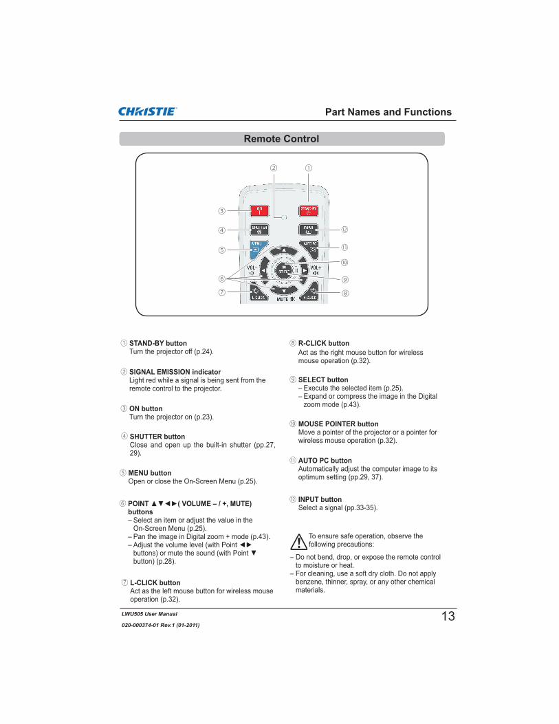
① STAND-BY buttonTurn the projector off (p.24).
③ ON buttonTurn the projector on (p.23).
⑫ INPUT buttonSelect a signal (pp.33-35).
⑦ L-CLICK buttonAct as the left mouse button for wireless mouse operation (p.32).
② SIGNAL EMISSION indicatorLight red while a signal is being sent from the remote control to the projector.
⑥ POINT ( VOLUME – / +, MUTE) buttons– Select an item or adjust the value in the
On-Screen Menu (p.25).– Pan the image in Digital zoom + mode (p.43).
button) (p.28).
To ensure safe operation, observe the following precautions:
– Do not bend, drop, or expose the remote control to moisture or heat.
– For cleaning, use a soft dry cloth. Do not apply benzene, thinner, spray, or any other chemical materials.
⑨ SELECT button– Execute the selected item (p.25).– Expand or compress the image in the Digital
zoom mode (p.43).
⑤ MENU buttonOpen or close the On-Screen Menu (p.25).
⑩ MOUSE POINTER buttonMove a pointer of the projector or a pointer for wireless mouse operation (p.32).
Part Names and Functions
⑪ AUTO PC buttonAutomatically adjust the computer image to its optimum setting (pp.29, 37).
④ SHUTTER buttonClose and open up the built-in shutter (pp.27, 29).
Remote Control
⑧ R-CLICK buttonAct as the right mouse button for wireless mouse operation (p.32).
⑫
⑪
⑧
⑩
①
③
④
⑥
⑤
⑦
⑨
②
13

LWU505 User Manual
020-000374-01 Rev.1 (01-2011)
⑰ ZOOM buttonsZoom in and out the images (p.29).
㉕ D.ZOOM buttonSelect the Digital zoom +/- mode and resize the image (p.43).
⑱ PIP buttonOperate the Picture in Picture function (pp.30, 55-56).
㉑ FILTER button Scroll the filter (p.30).
⑮ FREEZE buttonFreeze the picture on the screen (p.30).
㉔ KEYSTONE buttonCorrect keystone distortion (pp.31, 44, 50).
⑲ ON/OFF switchWhen using the remote control, set this switch to “ON”. Set it to “OFF” for power saving when it is not in use (p.16).
⑯ LENS SHIFT buttonSelect the Lens Shift function (p.29).
⑬ P-TIMER buttonOperate the P-timer function (pp.30, 60).
㉚ NUMBER buttonsAct as number buttons. Use these buttons when setting the remote control codes (p.16) or when entering the PIN code numbers (pp. 23, 54, 62).
㉙ POINTER buttonAct as the On-Off switch for the Pointer (pp.30, 32, 60).
Part Names and Functions
㉖ INPUT 1- 3 buttonsSelect an input source (INPUT 1 – INPUT 3) (pp.33-35).
Remote Control
㉒ FOCUS buttonsAdjust the focus (p.29).
㉘ SCREEN buttonSelect the screen size (p.29).
㉓ INFO. buttonDisplay the input source information (p.29).
⑭ IMAGE SEL. buttonOperate the image selection function (pp.40, 46).
㉗ IMAGE ADJ. buttonOperate the image adjustment function (pp.41-42, 47-48).
⑯
⑮
⑲
⑰
⑱
㉓㉒
㉔
㉕
For PIN code and remote control code.
㉖
㉑
⑳
㉗⑭
㉙㉘
㉚
⑬
⑳ WIRED REMOTE jackConnect the remote control cable (not supplied) to this jack when using as a wired remote control.
14

LWU505 User Manual
020-000374-01 Rev.1 (01-2011)
1 2 3Open the battery compartment lid.
Install new batteries into the compartment.
Replace the compartment lid.
Two AAA size batteriesFor correct polarity (+ and –), be sure battery terminals are in contact with pins in the compartment.
To ensure safe operation, please observe the following precautions :
and install new batteries.
rule or guidelines.
Point the remote control toward the projector (to Infrared Remote Receivers) when pressing the buttons. Maximum operating range for the remote control is about 16.4’ (5 m) and 60 degrees in front, back and top of the projector.
Infrared Remote Receivers are provided in front, back and top of the projector. You can conveniently use all of the receivers (pp. 10, 11, 59).
16.4’(5 m)
The remote control can be used as a wired remote control. Wired remote control helps you use the remote control outside of the operating range (16.4’/ 5 m). Connect the remote control and the projector with the remote control cable (sold separately). Connected with the remote control cable, the remote control does not emit wireless signal.
Part Names and Functions
16.4’(5 m)Note:
Remote Control Battery Installation
Wired Remote Control Transmitter
Remote Control Receivers and Operating Range
15

LWU505 User Manual
020-000374-01 Rev.1 (01-2011)
The eight different remote control codes (Code 1–Code 8) are assigned to this projector. Switching the remote control codes prevents interference from other remote controls when several projectors or video equipment next to each other are being operated at the same time. Change the remote control code for the projector first before changing that for the remote control. See “Remote control” in the Setting Menu on page 58.
Press and hold the MENU and a number button (1–8) for more than five seconds to switch among the codes.
Press and hold the MENU and a number button (1-8) that corresponds to the remote control code for more than five seconds to switch among the codes.
Part Names and Functions
Remote Control Code
AdjustableFeet
Projection angle can be adjusted up to 4.0 degrees with the adjustable feet.
Rotate the adjustable feet and tilt the projector to the proper height; to raise the projector, rotate the feet of both clockwise.
To lower the projector or to retract the adjustable feet, rotate the feet of both counterclockwise.
MENU button
Number buttons(1-8)
ON/OFFSwitch
1
2 To reset the remote control code, press and hold the MENU and the number button 0 for more than five seconds.
Adjustable Feet
16

LWU505 User Manual
020-000374-01 Rev.1 (01-2011)
Installation
For projector positioning, see the figures below. The projector should be set perpendicularly to the plane of the screen.
Note:
100''
46.1' (14.0 m)
34.6' (10.5 m)
23.0' (7.0 m)
11.4' (3.5 m)
200''
300''
400''
236''
177''118''
59''40''
Max. Zoom
Min. Zoom
Screen Size(W x H) mm
16:10 aspect ratio
Zoom (min.)
40''
Zoom (max.)
862 x 538
4.5'(1.4 m)
7.7'(2.4 m)
100''
2154 x 1346
11.4' (3.5 m)
19.5' (5.9 m)
200''
4308 x 2692
23.0' (7.0 m)
39.2' (12.0 m)
300''
6462 x 4039
34.6'(10.5 m)
58.9' (18.0 m)
400''
8616 x 5385
46.1'(14.0 m)
78.6' (24.0 m)
(Inch Diagonal)
(Center)
78.6' (24.0 m)
400''
4.5'(1.4 m)
60%
10%
Lens shift center position
Shift range
Projection lens can be moved from side to side and up and down with the motor-driven lens shift function. This function makes the positioning of images easy on the screen. (See page 27)
The display position can be shifted upward up to 60% elevation of the display.
The display position can be shifted downward up to 60% low level of the display.
The display position can be shifted to the left in up to 10% width of the display.
The display position can be shifted to the right in up to 10% width of the display.
When the lens is shifted to top. When the lens is shifted to bottom.
When the lens is shifted to leftmost. When the lens is shifted to rightmost.
Lens shift adjustable range
Positioning the Projector
Lens Shift Adjustment
17

LWU505 User Manual
020-000374-01 Rev.1 (01-2011)
When replacing the lens or using an optional lens, install the lens by following the instructions below. Ask the sales dealer for detailed information of the optional lens specifications.
Shift the lens to the central position by using the Lens shift function (p.27).
1
2
Removing the lens
Lens release button
CAUTIONBe careful when handling the lens. Do not drop.
3
Installation
While pressing the Lens release button on the topof the cabinet, turn the lens counterclockwise untilit stops and pull it out slowly from the projector.
Turn off the projector and unplug the AC power cord.
NOTES ON LENS INSTALLATION
electrical shock, fire hazard or other accidents.
the projector.
Fit the lens to the projector by aligning the red dot on the lens with the red dot of the projector.
Slowly turn the lens clockwise until it clicks. Make sure that the lens is fully inserted to the projector.
Remove the lens mount cover.
CAUTIONDo not press the lens release button when attaching the lens.
Lens Installation
Attaching the lens to the projector
Reddots
1
2
3
18

LWU505 User Manual
020-000374-01 Rev.1 (01-2011)
Cables used for connection ( = Cables not supplied with this projector.)
Installation
See the next page for the signals that can output to the ANALOG OUT terminal.
*
Connecting to a Computer (Digital and Analog RGB)
MonitorOutput
BNCcable
DVIOutput
G B R H/V V
HDMI-DVI
cable
VGA cable
VGA cable USB
cable
USBport
MonitorOutput
HDMIANALOG IN
ANALOGOUT
SerialCrosscable
CONTROL PORT
Serialout*Monitor Input
USBDIGITAL IN
DVI-Digitalcable
MonitorOutput
19

LWU505 User Manual
020-000374-01 Rev.1 (01-2011)
Cables used for connection ( = Cables not supplied with this projector.)
Installation
Analog Out Signal Table
A cable with one end D-sub 15 and the other end (Black box) compatible with each equipment is necessary.
Connecting to Video Equipment (Video, S-video, HDMI)
RGB Scart21-pin Output
S-videocable
S-video Output
Composite Video
Y - Pb/Cb - Pr/Cr
BNCcable
Component Video Output
Composite Video
Component Video Output (Y, Pb/Cb, Pr/Cr)
HDMI Output
HDMIcable
Scart-VGA cable
Video HDMIANALOG IN
ANALOG OUT
S-VIDEO
Refer to the Analog Out Signal Table (above).
Video Y - Pb/Cb - Pr/Cr
DVI-Digitalcable
DIGITAL IN
RCA cable
Digital Output(HDCP
compatible)
Input Terminal Monitor Out Cable
Input 1
D-sub15RGB (PC analog) YESRGB (SCART) NO
DVIRGB (PC digital) NORGB (AV HDCP) NO
HDMI HDMI NO
Input 2 5 BNCRGB YESVideo YESY, Pb/Cb, Pr/Cr YES
Input 3RCA Y, Pb/Cb, Pr/Cr YESS-video S-video NOVideo Video YES
Network NO
20

LWU505 User Manual
020-000374-01 Rev.1 (01-2011)
Cables used for connection ( = Cables not supplied with this projector.)
Installation
AudioOutput
AUDIO IN 1/2
Audio Output
Audiocable(stereo)
(R) (L)
External Audio Equipment
Audio Input
AUDIO OUT (stereo)
(R) (L)
(R) (L)
Audiocable
Audiocable(stereo) Audio
cable(stereo)
Connecting for Audio Signal
21

LWU505 User Manual
020-000374-01 Rev.1 (01-2011)
This projector uses nominal input voltages of 100–240 V AC and it automatically selects the correct input voltage. It is designed to work with single-phase power systems having a grounded neutral conductor. To reduce the risk of electrical shock, do not plug into any other type of power system.If you are not sure of the type of power being supplied, consult your authorized dealer or service center.Connect the projector with all peripheral equipment before turning on the projector.
Installation
NOTE ON THE POWER CORDAC power cord must meet the requirements of the country where you use the projector.Confirm the AC plug type with the chart below and proper AC power cord must be used.If the supplied AC power cord does not match your AC outlet, contact your sales dealer.
Projector side AC Outlet side
To POWER CORD CONNECTOR on your projector.
Ground
To the AC Outlet.(120 V AC)
For Continental EuropeFor the U.S.A. and Canada
To the AC Outlet.(200–240 V AC)
Note:
CAUTION
The AC outlet must be near this equipment and must be easily accessible.
Connecting the AC Power Cord
Connect the AC power cord (supplied) to the projector.
22

LWU505 User Manual
020-000374-01 Rev.1 (01-2011)
Connect the projector’s AC power cord into an AC outlet. The LAMP indicator lights red and the POWER indicator lights green.Press the ON/STAND-BY button on the side control or the ON button on the remote control. The LAMP indicator dims and the cooling fans start to operate. The preparation display appears on the screen and the countdown starts.
2
3
1
The preparation display will disappear after 30 seconds.
4 After the countdown, the input source that was selected the last time and the Lamp control status icon (see page 57) appear on the screen.
Selected Input Source and Lamp control
Complete peripheral connections (with a computer, VCR, etc.) before turning on the projector.
Note:
User 1-5
(See page 57 for Lamp control status.)
Lamp control statusIf the projector is locked with a PIN code, PIN code input dialog box will appear.
Note:Off
Countdown off Off
Mode 3
After the OK icon disappears, you can operate the projector.
PIN Code Input Dialog Box
Note:
Enter a PIN code
buttons on the remote control to enter a number. When using side control
move the red frame pointer to the next box. The number changes to . Repeat this step to complete entering a four-digit number. After entering the four-digit number, move the pointer to “Set”. Press the SELECT button so that you can start to operate the projector.When using remote controlPress the Number buttons on the remote control to enter a number (p.14). When you complete entering a four-digit number, the pointer moves to “Set”. Press the SELECT button so that you can start to operate the projector.If you fix anmove the pointer to the number you want to correct, and then enter the correct number.If you entered an incorrect PIN code, “PIN code” and the number ( ) will turn red for a moment. Enter the correct PIN code all over again.
Turning On the Projector
Input 1
RGB(PC analog)
Basic Operation
16
23

LWU505 User Manual
020-000374-01 Rev.1 (01-2011)
Basic Operation
What is PIN code?PIN (Personal Identification Number) code is a security code that allows the person who knows it to operate the projector. Setting a PIN code prevents unauthorized use of the projector.
A PIN code consists of a four-digit number. Refer to the PIN code lock function in the Setting Menu on pages 61-62 for locking operation of the projector with your PIN code.
CAUTION ON HANDLING PIN CODEIf you forget your PIN code, the projector can no longer be started. Take a special care in setting a new PIN code; write down the number in a column on page 87 of this manual and keep it on hand. Should the PIN code be missing or forgotten, consult your dealer or service center.
Press the ON/STAND-BY button on the side control or the STAND-BY button on the remote control, and after the countdown is over, Power off? appears on the screen.
Press the ON/STAND-BY button on the side control or the STAND-BY button on the remote control again to turn off the projector. The LAMP indicator lights bright and the POWER indicator turns off. After the projector is turned off, the cooling fans operate for 90 seconds. You cannot turn on the projector during this cooling down period.
1
2
TO MAINTAIN THE LIFE OF THE LAMP, ONCE YOU TURN THE PROJECTOR ON, WAIT AT LEAST FIVE MINUTES BEFORE TURNING IT OFF.
3 When the projector has cooled down enough, the POWER indicator lights green and then you can turn on the projector. To unplug the AC power cord, wait until the projector is completely cooled down.
Power off? disappears after 4 seconds.
Note:
On
DO NOT OPERATE THE PROJECTOR CONTINUOUSLY WITHOUT REST. CONTINUOUS USE MAY RESULT IN SHORTENING THE LAMP LIFE. TURN OFF THE PROJECTOR AND LET STAND FOR ABOUT AN HOUR IN EVERY 24 HOURS.
Turning Off the Projector
Note:ON
Power off?
You can disconnect the power cord from the wall outlet or turn off the breaker even during projection without pressing the ON/STAND-BY button.Note:
Direct OFF Function
24

LWU505 User Manual
020-000374-01 Rev.1 (01-2011)
Basic Operation
How to Operate the On-Screen Menu
Side ControlMENU button
On-Screen Menu
Remote Control
The projector can be adjusted or set via the On-Screen Menu. The menu has a hierarchical structure, with a main menu that is divided into submenus, which are further divided into other submenus. For each adjustment and setting procedure, refer to respective sections in this manual.
SELECT button to access the submenu items. (The selected item is highlighted in orange.)
submenu item and press the SELECT button to set or access the selected item.
Press the MENU button on the side control or the remote control to display the On-Screen Menu.
1
2
3
setting or switch between each option and press the SELECT button to activate it and return to the submenu.
4
menu. Press the MENU button to exit the On-Screen Menu.
5
Point
or SELECT button
Dynamic
Dynamic
The selected item ishighlighted in orange.
The currently set item is marked.
POINT buttons
SELECT button
POINT buttons
SELECT button
MENU button
Pointbutton
25

LWU505 User Manual
020-000374-01 Rev.1 (01-2011)
Basic Operation
For detailed functions of each menu, see “Menu Tree” on pages 76-78.Main Menu Sub-Menu
Image selectFor computer source, used to select an image level among Dynamic, Standard, Real, and Image 1-10(p.40).For Video source, used to select an image level among Dynamic, Standard, Natural, Cinema, andImage 1-10 (p.46).Image adjustFor computer source, used to adjust the computer image. [Contrast/Brightness/Iris/Color temp./Whitebalance (R/G/B)/Offset(R/G/B)/Sharpness/Gamma/Reset/Store] (pp.41-42). For video or HDMI source, used to adjust the video image. [Contrast/Brightness/Color/Tint/Iris/Colortemp./White balance (R/G/B)/Offset (R/G/B)/Sharpness/Gamma/Noise Reduction/Progressive/Reset/Store] (pp.47-48).
PC adjustUsed to adjust the parameters to match with the input signal format (pp.37-39).
ScreenFor computer source, used to adjust the size of the image. [Normal/Full/Wide(16:9)/Zoom/True/Custom/Custom adj./Digital zoom +/-/Keystone/Ceiling/Rear/Screen aspect/Reset] (pp.42-44).For video or HDMI source, used to adjust the size of the image. [Normal/Full/Wide(16:9)/Zoom/NaturalWide/Custom/Custom adj./Keystone/Ceiling/Rear/Screen aspect/Reset] (pp. 49-50).
InputUsed to select an input source (Input 1, Input 2, Input 3 or Network) (p.33).
: Network
SoundUsed to adjust the volume or mute the sound (p.28).
InformationDisplay the input source information: Input, System, H-sync freq., V-sync freq., Screen, Language,Lamp status, Lamp counter, Filter counter, Power management, Key lock, PIN code lock, Shutter management, Simple mode, Remote control, and SERIAL NO. (p.29).
GuideThe key operation is displayed.
SettingUsed to set the projector’s operating configurations (pp.51-65).
NetworkSee the user manual of “Network Set-up and Operation”.
Main Menu
26

LWU505 User Manual
020-000374-01 Rev.1 (01-2011)
The following lens operation can be made with the LENS button on the side control.
Press the LENS button to enter each lens operation mode. The selected adjustment display appears on the screen.
Display Lens shift buttons to position the screen to the desired point without having picture distortion. The screen can be moved up or down to 60 percent, or sideways up to 10 percent from the central axis of the lens shift.Press and hold the LENS button for more than 5 seconds to return to the central position.
Lens Shift Adjustment
Note:
Display Zoomto zoom in and out the image.
Zoom Adjustment
Display Focusto adjust focus of the image.
Focus Adjustment
Lens Operation
Basic Operation
Shutter FunctionShutter function allows you to completely block out light to the screen. Press the SHUTTER button to close the shutter inside the projector. To open up the shutter, press the SHUTTER button again. Refer to p.63 for details of setting for the Shutter function.
Note:
On
Operating with Projector Control
Side Control
Zoom
SHUTTER button
LENS button
POINT buttons
Focus
Lens shift
27

LWU505 User Manual
020-000374-01 Rev.1 (01-2011)
Side Control
Basic Operation
1
2
Press the MENU button to display the On-Screen
Soundto access the submenu items.
Press the VOLUME+/– buttons on the side control or on the remote control to adjust the volume. The volume dialog box appears on the screen for a few seconds.
control to select On to temporarily turn off the sound. To turn the sound back on, press the MUTE (Point
Off or press the VOLUME +/– buttons.
Press the SELECT button to switch the mute function On/Off. When the sound is turned off, On is displayed. Press the VOLUME +/– buttons again to turn the sound back on.
submenu item and press the SELECT button to access the selected item.
Volume
Volume
Mute
Mute
Sound Menu
Volume Dialog BoxApproximate level of the volume.
the Mute function On or Off.The dialog box disappears after 4 seconds.
SP function On/Off. When the Built-in SP sound is turned off, Off is displayed.
Built-in SP
Note:
Network
Remote Control
VOLUME +/– buttons
Sound Adjustment
Direct Operation
Menu Operation
VOLUME + button
VOLUME – button
MUTE (Point button
28
LWU505 User Manual
020-000374-01 Rev.1 (01-2011)
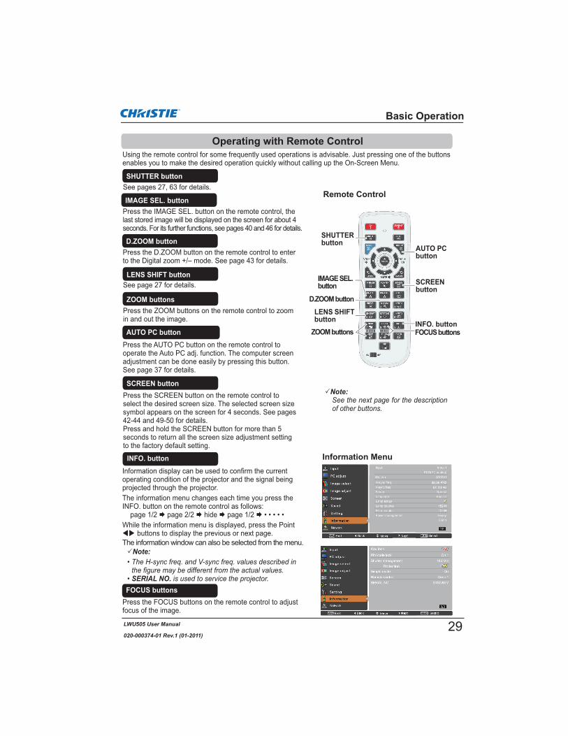
Using the remote control for some frequently used operations is advisable. Just pressing one of the buttons enables you to make the desired operation quickly without calling up the On-Screen Menu.
Press the ZOOM buttons on the remote control to zoom in and out the image.
ZOOM buttons
Press the FOCUS buttons on the remote control to adjust focus of the image.
FOCUS buttons
See page 27 for details.LENS SHIFT button
Remote Control
D.ZOOM button
SHUTTERbutton
AUTO PCbutton
ZOOM buttons FOCUS buttons
LENS SHIFT button
Note:
INFO. button
SHUTTER buttonSee pages 27, 63 for details.
SCREENbutton
INFO. button
Press the AUTO PC button on the remote control to operate the Auto PC adj. function. The computer screen adjustment can be done easily by pressing this button. See page 37 for details.
AUTO PC button
Press the SCREEN button on the remote control to select the desired screen size. The selected screen size symbol appears on the screen for 4 seconds. See pages 42-44 and 49-50 for details.Press and hold the SCREEN button for more than 5 seconds to return all the screen size adjustment setting to the factory default setting.
SCREEN button
Press the D.ZOOM button on the remote control to enter to the Digital zoom +/– mode. See page 43 for details.
D.ZOOM button
Information display can be used to confirm the current operating condition of the projector and the signal being projected through the projector.The information menu changes each time you press theINFO. button on the remote control as follows:
page 1/2 page 2/2 hide page 1/2 While the information menu is displayed, press the Point
buttons to display the previous or next page.The information window can also be selected from the menu.
Operating with Remote Control
Information Menu
Note:
SERIAL NO.
Basic Operation
IMAGE SEL.button
IMAGE SEL. buttonPress the IMAGE SEL. button on the remote control, the last stored image will be displayed on the screen for about 4 seconds. For its further functions, see pages 40 and 46 for details.
29

LWU505 User Manual
020-000374-01 Rev.1 (01-2011)
Press the FREEZE button on the remote control to freeze the picture on the screen, meanwhile, volume is muted. To cancel the FREEZE function, press the FREEZE button again or press any other button.
Fig.1 will appear when the Freeze function is working.
FREEZE button
FILTER buttonPress and hold the FILTER button for more than 5 seconds to operate electrically operated filter to replace the filter.
Remote Control
POINTER button
FILTER button
Note:
MOUSEPOINTER button
Basic Operation
Note:
0
FREEZE button
P-TIMER button
Move the pointer on the screen with this button.
MOUSE POINTER button
POINTER button
P-TIMER button
Fig.1
PIP button
Press the PIP button on the remote control several times until the desired mode of Picture in Picture appears. Each user mode (User 1-5) appears only when it has stored data.Press and hold the PIP button for more than 3 seconds to display the setting dialog box of Picture in Picture. See pages 55-56 for details of Picture in Picture function.
PIP button
User 1 of PIP (example)
User 2 of PIP (example)
Mainpicture
Subpicture
SubpictureMain
picture
IMAGE ADJ. button
IMAGE ADJ. button
Press POINTER button on the remote control to display the Pointer on the screen. (see pages 32, 60)
Press the P-TIMER button on the remote control to operate the Count up/Count down function. See page 60 for details of Setting for the P-timer function.
To stop the count time, press the P-TIMER button. To cancel the P-timer function, press and hold the P-TIMER button for a few seconds.
Press the IMAGE ADJ. button on the remote control to display the On-Screen Menu of Image Adjustment. See pages 41-42 and 47-48 for details of its functions. To cancel its function, press the IMAGE ADJ. button directly over again.
30

LWU505 User Manual
020-000374-01 Rev.1 (01-2011)
Remote Control
POINTbuttons
KEYSTONE button
Basic Operation
If a projected picture still has keystone distortion after pressing the AUTO PC button on the remote control, correct the image manually as follows:Press the KEYSTONE button on the remote control to switch the Standard (for Vertical/Horizontal) /Corner correction adjustment. The Standard or Corner correction adjustment dialog box appears. Use the Point buttons to correct the Standard or Corner distortion. The Standard or Corner correction adjustment can be stored (see pages 44, 50).
Note:
OffRed White Blue
Reduce the top left corner part with the Point buttons.
Keystone
Reduce the top right corner part with the Point buttons.
Keystone Keystone
Keystone
Reduce the bottom left corner part with the Point
buttons.
Reduce the bottom right corner part with the Point
buttons.
Press the KEYSTONE button on the remote control to switch Corner correction adjustment, press the SELECT button on the remote control to select the corner you want to adjust.
Reduce the right part with Point button.
Reduce the upper width with the Point button.
Reduce the left part with Point button.
Reduce the lower width with the Point button.
Press the SELECT button
Press the SELECT button
Press the SELECT button
Press the SELECT button
KeystoneKeystone
The top left corner adjustment as an example:
Press the
button
Press the Point button
Keystone Correction
Standard
Corner correction
Keystone
31
LWU505 User Manual
020-000374-01 Rev.1 (01-2011)
Note:Dot/Arrow
Finger
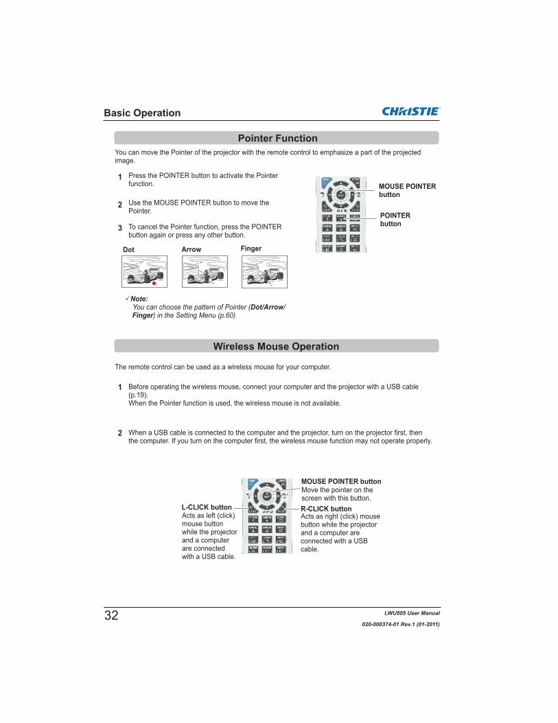
You can move the Pointer of the projector with the remote control to emphasize a part of the projected image.
Press the POINTER button to activate the Pointer function.
1
2
3 To cancel the Pointer function, press the POINTER button again or press any other button.
Use the MOUSE POINTER button to move the Pointer.
The remote control can be used as a wireless mouse for your computer.
Before operating the wireless mouse, connect your computer and the projector with a USB cable (p.19).When the Pointer function is used, the wireless mouse is not available.
When a USB cable is connected to the computer and the projector, turn on the projector first, then the computer. If you turn on the computer first, the wireless mouse function may not operate properly.
1
2
Basic Operation
Pointer Function
Wireless Mouse Operation
Dot Arrow Finger
MOUSE POINTER button
POINTERbutton
Move the pointer on the screen with this button.
MOUSE POINTER button
R-CLICK buttonL-CLICK buttonActs as right (click) mouse button while the projector and a computer are connected with a USB cable.
Acts as left (click) mouse button while the projector and a computer are connected with a USB cable.
32

LWU505 User Manual
020-000374-01 Rev.1 (01-2011)
The input source changes each time you press the INPUT button on the side control or the remote control as follows:
Before using the INPUT button on the side control or the remote control, you must select a correct input source by On-Screen Menu and the latest input source will be displayed.
Input Selection
Press the INPUT 1, INPUT 2, or INPUT 3 button on the remote control. The input source appears on the screen as you press each button. Select the connected input source.
INPUT 1 button
Input 1
RGB (PC analog)
RGB (Scart)
HDMI
INPUT 2 button
Input 2
Video
Y,Pb/Cb,Pr/Cr
RGB
INPUT 3 button
Input 3
Video
Y,Pb/Cb,Pr/Cr
S-video
Side Control Remote Control
* Only the Input button function is set Mode 1 in the Setting menu, the INPUT button is used for switching input source. (p.51)
INPUT button*
Direct Operation
Remote Control Operation
Side Control/Remote Control Operation
INPUT 1/2/3 buttons
Remote Control
INPUT button*
RGB (AV HDCP)
RGB (PC digital)
33

LWU505 User Manual
020-000374-01 Rev.1 (01-2011)
INPUT MENU
When your computer is connected to the INPUT 1 (ANALOG) terminal, select RGB (PC analog).
RGB(PC analog)
Note:
When connecting the computer output [5 BNC Type (Green, Blue, Red, Horiz. Sync, and Vert. Sync.)] from the computer to G, B, R, H/HV, and V jacks:
Input Selection
When your computer is connected to the INPUT 2 (5 BNC INPUT JACKS) terminal, select RGB.
RGB
1
2
3
Press the MENU button to display the On-Screen Input and
submenu items.
source and then press the SELECT button.
INPUT 2 MENU
INPUT 1 MENU
Computer Input Source Selection
WHEN SELECTING INPUT 1 (COMPUTER INPUT TERMINALS )
WHEN SELECTING INPUT 2 (5 BNC INPUT JACKS )
Menu Operation
34

LWU505 User Manual
020-000374-01 Rev.1 (01-2011)
When the video input signal is connected to the Y-Pb/Cb-Pr/Cr jacks, select Y,Pb/Cb,Pr/Cr.
When the video input signal is connected to the VIDEO jack, select Video.
When the video input signal is connected to the S-VIDEO jack, select S-video.
When connecting to video equipment, select the type of Video source in the Source Select Menu.
When the video input signal is connected to the Y-Pb/Cb-Pr/Cr jacks, select Y,Pb/Cb,Pr/Cr.
When the video input signal is connected to the VIDEO jack, select Video.
When connecting to video equipment, select the type of Video source in the Source Select Menu.
Video
Y,Pb/Cb,Pr/Cr
Video
S-video
When connecting to video equipment, select the type of Video source in the Source Select Menu.
INPUT 1 MENU
HDMI
RGB(Scart)When scart video equipment is connected to the INPUT 1 (ANALOG) terminal, select RGB (Scart).
When the video signal is connected to the HDMI terminal, select HDMI.
INPUT 2 MENU
INPUT 3 MENU
Y,Pb/Cb,Pr/Cr
1
2
3
Press the MENU button to display the On-Screen Input and
submenu items.
source and then press the SELECT button.
Video Input Source SelectionMenu Operation
Note:
Y,Pb/Cb,Pr/Cr RGB
RGB
WHEN SELECTING INPUT 1 (COMPUTER INPUT TERMINALS )
WHEN SELECTING INPUT 2 (5 BNC INPUT JACKS )
WHEN SELECTING INPUT 3 (AV TERMINALS )
RGB(AV HDCP)If the HDCP-compatible signal source is connected to the INPUT 1 (DIGITAL) terminal, select RGB (AV HDCP).
Input Selection
35

LWU505 User Manual
020-000374-01 Rev.1 (01-2011)
Computer Input
PC System Menu
PC System Menu
1
2
PC system can also be selected manually.
The PC System Menu Selected system is displayed.
Press the MENU button to display the On-Screen Input
System and
system and then press the SELECT button.3
Systems in this dialog box can be selected.
Customized Mode (1-10)set in the PC adjust Menu (pp.38-39).
This projector automatically tunes to various types of computers with its Multi-scan system and Auto PC adjustment. If a computer is selected as a signal source, this projector automatically detects the signal format and tunes to project a proper image without any additional settings. (Signal formats provided in this projector are shown on pages 82-83)
One of the following messages may appear when:
There is no signal input from the computer. Check the connection between your computer and the projector. (See “Troubleshooting” on pp. 73-75.)
Auto
- - - -
The preset system is manually adjusted in the PC adjust Menu. The adjusted data can be stored in Mode 1-10 (pp.38-39).
Mode 1
PC Systems provided in this projector is chosen. The projector chooses a proper system provided in the projector and displays it.
SVGA 1
*Mode 1 and SVGA 1 are examples.
Computer System Selection
Automatic Multi-Scan System
Selecting Computer System Manually
When the projector cannot recognize the connected signal conforming to the provided PC Systems, Auto is displayed on the System Menu box and the Auto PC adjustment function works to display proper images. If the image is not projected properly, a manual adjustment is required (pp. 38-39).
36

LWU505 User Manual
020-000374-01 Rev.1 (01-2011)
Auto PC Adjustment function is provided to automatically adjust Fine sync, Total dots, Position H and Position V to conform to your computer.
To store the adjusted parameters:The adjusted parameters from the Auto PC Adjustment can be stored in the projector. Once the parameters are stored, the setting can be done just by selecting Mode in PC SYSTEM Menu (p.36). See “Manual PC Adjustment” on pages 38-39.
The Auto PC adjustment function can be operated directly by pressing the AUTO PC button on the remote control.
Remote Control
Computer Input
PC adjust MenuPress the MENU button to display the On-Screen
PC adjust1
2 Auto PC adj. and then press the SELECT button.
select Auto PC adj. and press the SELECT button.Please wait... appears while the Auto PC adjustment is in process.
Auto PC Adjustment
Direct Operation
Menu Operation
Auto PC adj.
AUTO PC button
Note:
480i 575i 480p 575p 720p 1035i, 1080i1080p
37
LWU505 User Manual
020-000374-01 Rev.1 (01-2011)
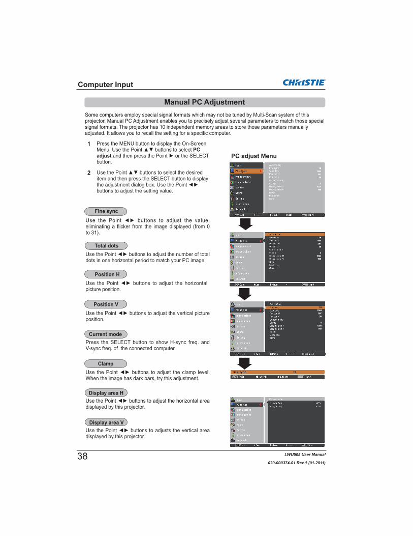
Some computers employ special signal formats which may not be tuned by Multi-Scan system of this projector. Manual PC Adjustment enables you to precisely adjust several parameters to match those special signal formats. The projector has 10 independent memory areas to store those parameters manually adjusted. It allows you to recall the setting for a specific computer.
eliminating a flicker from the image displayed (from 0 to 31).
dots in one horizontal period to match your PC image.
picture position.
position.
Press the SELECT button to show H-sync freq. and V-sync freq. of the connected computer.
When the image has dark bars, try this adjustment.
displayed by this projector.
displayed by this projector.
Computer Input
PC adjust Menu
1
2
Press the MENU button to display the On-Screen PC
adjustbutton.
item and then press the SELECT button to display
buttons to adjust the setting value.
Fine sync
Total dots
Position H
Position V
Current mode
Clamp
Display area H
Display area V
Manual PC Adjustment
38

LWU505 User Manual
020-000374-01 Rev.1 (01-2011)
Computer Input
Note:Display area (H/V) 480i575i 480p 575p 720p 1035i 1080i 1080p
Vacant
This mode has stored parameters.
Values of Total dots,Position H, Position V,Display area H and Display area V.
Press the SELECT button to store the data.
Press the MENU button to close this dialog box.
Mode free
Store
To store the adjusted data, select Store and then press the Point the SELECT button. Move the highlight to one of the Modes 1 to 10 in which you want to store, and then press the SELECT button.
To clear the stored data, select Mode free and then press the Point the SELECT button. Move the highlight to the Mode that you want to clear and then press the SELECT button.
To reset the adjusted data, select Reset and press the SELECT button. A confirmation box appears and then select Yes. All adjustments will return to their previous figures.
Reset
Mode free
Store
Press the SELECT button to clear the stored data.
39

LWU505 User Manual
020-000374-01 Rev.1 (01-2011)
Computer Input
Image Level Selection
1
2
Normal picture level preset on the projector.
Picture level with improved halftone for graphics.
User preset picture adjustment in the Image adjust Menu. (pp.41-42)
Image select Menu
Press the MENU button to display the On-Screen Image
selectbutton. The factory default setting is Standard.
item and then press the SELECT button.
Menu Operation
Standard
Real
Image 1–10
For viewing pictures in a bright room.Dynamic
* The factory default setting is Standard.
Direct Operation
The Image Selection function can be operated directly by pressing the IMAGE SEL. button on the remote control. the last stored image will be displayed on the screen for about 4 seconds.
IMAGE SEL.button
40
LWU505 User Manual
020-000374-01 Rev.1 (01-2011)
Computer Input
Image adjust Menu
Press the MENU button to display the On-Screen Image
adjustbutton.
1
2and then press the SELECT button to display the
adjust the setting value.
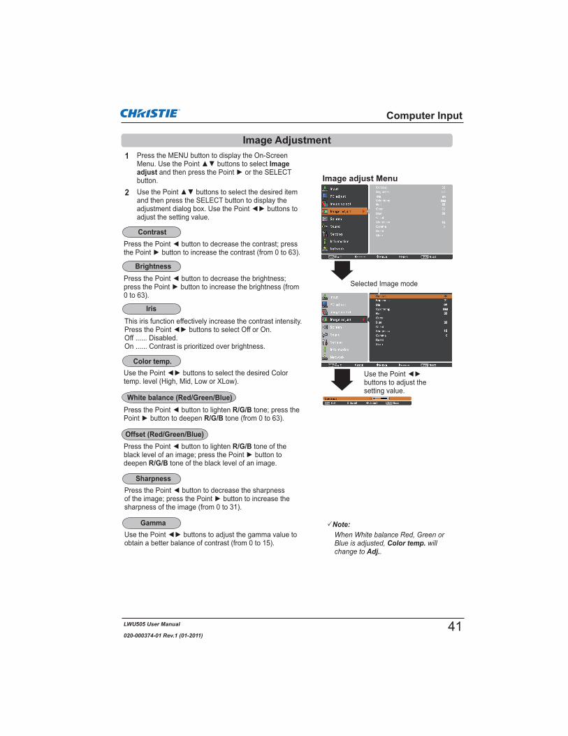
Note:
Color temp.Adj.
0 to 63).
R/G/B tone; press the R/G/B tone (from 0 to 63).
temp. level (High, Mid, Low or XLow).
obtain a better balance of contrast (from 0 to 15).
sharpness of the image (from 0 to 31).
buttons to adjust the setting value.
Selected Image mode
R/G/B tone of the
deepen R/G/B tone of the black level of an image.
Image Adjustment
Contrast
Brightness
Color temp.
Sharpness
Gamma
This iris function effectively increase the contrast intensity.
Off ...... Disabled.On ...... Contrast is prioritized over brightness.
Iris
White balance (Red/Green/Blue)
Offset (Red/Green/Blue)
41

LWU505 User Manual
020-000374-01 Rev.1 (01-2011)
Select the desired screen size that conforms to the input signal source.
SCREEN MENU
Provide the image within a screen size keeping its original aspect ratio.
Note:
Full Zoom True Custom adj. Digital zoom +/–
1
2
Press the MENU button to display the On-Screen Screen
and then press the SELECT button.
To reset the adjusted data, select Reset and press the SELECT button. A confirmation box appears and then select Yes. All adjustments will return to their previous figures.
To store the adjusted data, select Store and press the
to select one from Image 1 to 10 and press the SELECT button.A confirmation box appears and then select Yes. Stored data can be called up by selecting an Image (1-10) in the Image Mode Selection on page 40.
A confirmation box appears and then select Yes.
Store
Computer Input
Reset
Store
Screen Size Adjustment
Normal
Provide the image in its original size. When the original image size is larger than the panel size (1920 x 1200), and 16:9 or 4:3 is selected in Screen aspect, the projector goes to the panning mode automatically. Use
adjusted, the arrows will turn red. When reaching to the correction limits, the arrows will disappear.
Scale the image proportionally to fit the entire screen. Either side of image may go over the screen.
True
Zoom
Provide the image to fit full screen size.Full
Provide the last stored aspect screen image. Custom
Provide the image at the 16:9 wide screen ratio.Wide (16:9)
42

LWU505 User Manual
020-000374-01 Rev.1 (01-2011)
Computer Input
Adjust the screen scale and position manually with this function.
Custom adj. and Custom adj. is displayed on the screen,
want to adjust.Scale H/V ........ Adjust the Horizontal/Vertical screen
scale.H&V ................. When set to On, the aspect ratio is fixed.
Scale V appears dim and becomes unavailable. Adjust Scale H, and then the screen scale is automatically modified based on the aspect ratio.
Position H/V ... Adjust the Horizontal/Vertical screen position.
Common ......... Save the adjusted scale to all the inputs. Press the SELECT button at Common to display a confirmation box. To save the scale, press the SELECT button at Yes.When Custom is selected, the saved scale is used.
Reset ............... Reset all the adjusted values. Press the SELECT button at Reset to display a confirmation box. To reset, press the SELECT button at Yes.
Note:Normal
Scale H/VPosition H/V
Custom adj.
Custom adj.
Select Digital zoom +. The On-Screen Menu disappears and D. zoom + appears. Press the SELECT button to
pan the image. The Panning function can work only when the image is larger than the screen size.You can also enter the Digital zoom + mode by pressing the D.ZOOM button on the remote control.
You can also enter the Digital zoom - mode by pressing the D.ZOOM button on the remote control.
Select Digital zoom – . The On-Screen Menu disappears and D. zoom – appears. Press the SELECT button to compress image size. The projected image can be also compressed by pressing the D.ZOOM button on the remote control.
To return to the previous screen size, select a screen size from the Screen Size Adjustment Menu or select an input source from the Input Source Selection Menu (see pages 33-35) again or adjust the screen size with the D.ZOOM button.
Note:
True Digital zoom +/– 480i 575i 480p
575p
Digital zoom +/-True
Digital zoom – Custom
Digital zoom +
Digital zoom -
43

LWU505 User Manual
020-000374-01 Rev.1 (01-2011)
Computer Input
This function is used to adjust keystone distortion of theprojected image. Use the Point buttons to choose the item you want to adjust.
Keystone
This function returns all adjusted values to the factory default settings. Press the SELECT button at Reset to display a confirmation box. To reset, press the SELECT button at Yes.
Ceiling
Rear
When this function is set to On, the picture will be top/bottom and left/right reversed. This function is used to project the image from a ceiling-mounted projector.
When this function is set to On, the picture will be left/right reversed. This function is used to project the image from rear of the screen.
Keystone
Ceiling
Rear
Reset
Adjust the Horizontal/Vertical keystone distortion of the projected image.
Standard
Corner correctionAdjust the corner distortion of the projected image.
Corner patternChoose a Corner pattern mode among Red, White, Blue,and Off.
Store Store .... Keep the keystone correction even when the
AC power cord is unplugged.Reset .... Release the keystone correction when the
AC power cord is unplugged.Press the KEYSTONE button on the remote control to switch the Standard (for Vertical/Horizontal) /Corner correction adjustment. The Standard or Corner correction adjustment dialog box appears. Use the Point
buttons to correct the Standard or Corner distortion (p.31).
Screen aspectThis function is used to project the image to a 4:3 or 16:9 projection screen.Default (16:10) ....16:10 is the aspect of the LCD panel.
The original Screen Menu is available.16:9 ..................... Set to a 16:9 projection screen.4:3 ........................Set to a 4:3 projection screen.
Note:Natural wide
720p 1035i 1080i 1080p
Wide (16:9)
Natural wide
44

LWU505 User Manual
020-000374-01 Rev.1 (01-2011)
If the projector cannot reproduce proper video image, select a specific broadcast signal format from among PAL, SECAM, NTSC, NTSC 4.43, PAL-M, and PAL-N.
The projector automatically detects an incoming video signal, and adjusts itself to optimize its performance.When the Video System is 1035i, 1080i or 1080p,select the system manually.
If the projector cannot reproduce proper video image, select a specific component video signal format from among 480i, 575i, 480p, 575p, 720p, 1035i, 1080i, and 1080p.
Video Jack or S-video Jack
The projector automatically detects an incoming video system, and adjusts itself to optimize its performance.When Video System is PAL-M or PAL-N, select the system manually.
Video Input
1
AV System Menu (Video or S-video)
AV System Menu (Y, Pb/Cb, Pr/Cr)
2
Press the MENU button to display the On-Screen Input
System and then
3system and then press the SELECT button.
Note:
RGB (Scart)
Video System Selection
Auto
Y, Pb/Cb, Pr/Cr Jacks
PAL/SECAM/NTSC/NTSC4.43/PAL-M/PAL-N
Auto
Y, Pb/Cb, Pr/Cr SIGNAL FORMAT
45

LWU505 User Manual
020-000374-01 Rev.1 (01-2011)
Video Input
Image Level Selection
Normal picture level preset on the projector.
Picture level adjusted with fine tone.
User preset picture adjustment in the Image adjust Menu. (p.48)
Image select Menu
1
2
Press the MENU button to display the On-Screen Image
selectbutton.
item and then press the SELECT button.
Menu Operation
Standard
Cinema
Image 1–10
For viewing pictures in a bright room.Dynamic
Natural picture level preset on the projector. Natural
* The factory default setting is Standard.
Direct Operation
The Image Selection function can be operated directly by pressing the IMAGE SEL. button on the remote control. the last stored image will be displayed on the screen for about 4 seconds.
IMAGE SEL.button
46

LWU505 User Manual
020-000374-01 Rev.1 (01-2011)
1
2
0 to 63).
(from 0 to 63).
R/G/B tone; press R/G/B tone (from 0 to
63).
temp. level (High, Mid, Low or XLow).
of the color (from 0 to 63).
get a proper color balance (from 0 to 63).
Note:Adj.
Tint PAL SECAM PAL-M PAL-N
Image adjust Menu
Selected Image mode
Press the MENU button to display the On-Screen Image
adjustbutton.
and then press the SELECT button to display the
adjust the setting value.
to adjust the setting value.
Video Input
Image Adjustment
Contrast
Brightness
Color
Tint
Color temp.
White balance (Red/Green/Blue)
IrisThis iris function effectively increase the contrast intensity.
Off ...... Disabled.On ...... Contrast is prioritized over brightness.
47

LWU505 User Manual
020-000374-01 Rev.1 (01-2011)
to obtain a better balance of contrast (from 0 to 15).
sharpness of the image (from 0 to 31).
An interlaced video signal can be displayed in
change the progressive scan mode.Off............. Progressive scan mode is Off.On ............. Progressive scan mode is On.Film........... For watching a film. With this function,
the projector reproduces pictures faithful to the original film quality.
Noise interference on the screen can be reduced.
reduction mode.Off............. Noise reduction mode is Off.On ............. Noise reduction mode is On.
Note:Progressive 480p,575p, 720p, or 1080p Noise reduction
1080p
To reset the adjusted data, select Reset and press the SELECT button. A confirmation box appears and then select Yes. All adjustments will return to their previous figures.
To store the adjusted data, select Store and press
press the SELECT button. A confirmation box appears and then select Yes.Stored data can be called up by selecting an Image(1-10) in the Image Mode Selection on page 46.
A confirmation box appears and then select Yes.
Store
Video Input
R/G/B tone of the
deepen R/G/B tone of the black level of an image (from 0 to 63).
Offset (Red/Green/Blue)
Sharpness
Gamma
Noise reduction
Progressive
Reset
Store
48
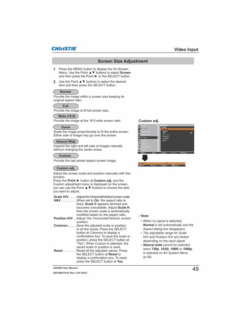
LWU505 User Manual
020-000374-01 Rev.1 (01-2011)
Note:
Normal
Natural wide720p 1035i 1080i 1080p
Video Input
Custom adj.
1
2
Press the MENU button to display the On-Screen Screen
item and then press the SELECT button.
Provide the image within a screen size keeping its original aspect ratio.
Provide the image at the 16:9 wide screen ratio.
Screen Size Adjustment
Normal
Wide (16:9)
Custom adj.
Scale the image proportionally to fit the entire screen. Either side of image may go over the screen.
Provide the image to fit full screen size.Full
Expand the right and left side of images naturally without changing the center areas.
Natural Wide
Zoom
CustomProvide the last stored aspect screen image.
Adjust the screen scale and position manually with this function.Press the Point button at Custom adj. and the Custom adjustment menu is displayed on the screen, you can use the Point you want to adjust.
Scale H/V Adjust the Horizontal/Vertical screen scale.H&V On, the aspect ratio is
fixed. Scale V appears dimmed and becomes unavailable. Adjust Scale H,then the screen scale is automatically modified based on the aspect ratio.
Position H/V Adjust the Horizontal/Vertical screen position.
Common Save the adjusted scale or position to all the inputs. Press the SELECT button at Common to display a confirmation box. To save the scale or position, press the SELECT button at "Yes", When Custom is selected, the saved scale or position is used.
Reset Reset all the adjusted values. Press the SELECT button at Reset to display a confirmation box. To reset, press the SELECT button at Yes.
49
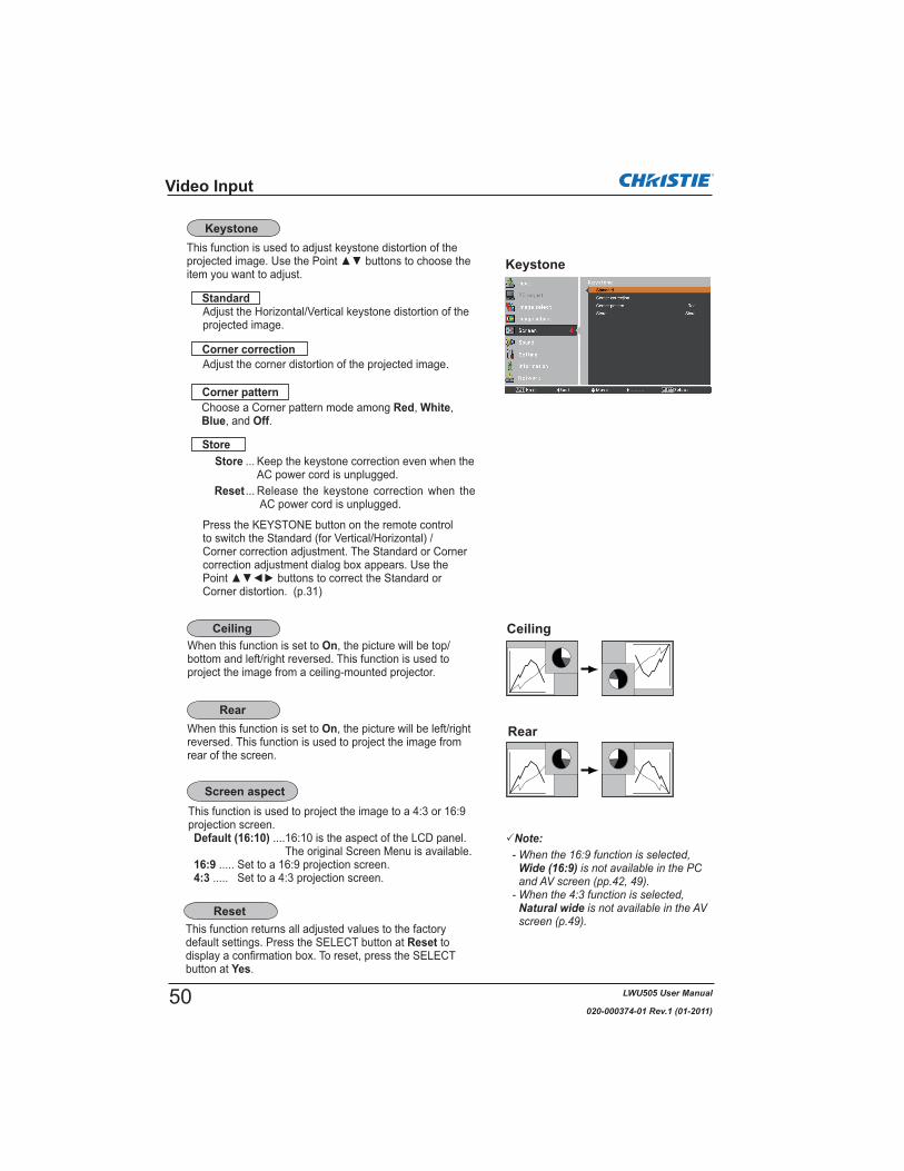
LWU505 User Manual
020-000374-01 Rev.1 (01-2011)
Video Input
This function returns all adjusted values to the factory default settings. Press the SELECT button at Reset to display a confirmation box. To reset, press the SELECT button at Yes.
Ceiling
Rear
When this function is set to On, the picture will be top/bottom and left/right reversed. This function is used to project the image from a ceiling-mounted projector.
When this function is set to On, the picture will be left/right reversed. This function is used to project the image from rear of the screen.
KeystoneThis function is used to adjust keystone distortion of the projected image. Use the Point buttons to choose the item you want to adjust.
Keystone
Adjust the Horizontal/Vertical keystone distortion of the projected image.
Standard
Corner correctionAdjust the corner distortion of the projected image.
Corner patternChoose a Corner pattern mode among Red, White,Blue, and Off.
Store Store ... Keep the keystone correction even when the
AC power cord is unplugged.Reset ... Release the keystone correction when the
AC power cord is unplugged.
Press the KEYSTONE button on the remote controlto switch the Standard (for Vertical/Horizontal) /Corner correction adjustment. The Standard or Corner correction adjustment dialog box appears. Use the Point buttons to correct the Standard or Corner distortion. (p.31)
Ceiling
Rear
Reset
This function is used to project the image to a 4:3 or 16:9 projection screen.Default (16:10) ....16:10 is the aspect of the LCD panel.
The original Screen Menu is available.16:9 ..... Set to a 16:9 projection screen.4:3 ..... Set to a 4:3 projection screen.
Screen aspect
Note:
Wide (16:9)
Natural wide
50

LWU505 User Manual
020-000374-01 Rev.1 (01-2011)
Setting
Setting Menu
Press the MENU button to display the On-Screen
Settingbutton to access the submenu items.
1
2
button to access the selected item.
This projector has a Setting menu that allows you to set up the other various functions described below.
3item and then press the SELECT button.
The language used in the On-Screen Menu is available in English, German, French, Italian, Spanish, Portuguese, Dutch, Swedish, Russian, Chinese, Korean and Japanese.
Language
PositionThis function is used to change the position of the On-Screen Menu. Select Position and press the SELECT button.The Position changes each time you press the SELECT button as follows.the center the bottom left the bottom right the top left the top right the center .....
This function detects the input signal automatically. When
buttons to select one of the following options.Mode 1...... Input search will not work.Mode 2...... Input search works under the following
situation: – When pressing the INPUT button on the
side control or the remote control.Mode 3...... Input search works under the following
situation:–When turning on the projector by pressing
the ON/STAND-BY button on the side control or pressing the ON button on the remote control.
–When pressing the INPUT button on the remote control or on the side control.
–When no signal is detected.
Setting
Language
Menu
Input button
Menu sizeThis function is used to change the display size of the On-Screen Menu. Select Menu size and press the SELECT button.
Normal Display the On-Screen Menu on the screen in its normal size.
Double Display the On-Screen Menu on the screen in its double normal size.
Note:4:3
DoubleNormal
Position
Note:Input button Mode 3
51

LWU505 User Manual
020-000374-01 Rev.1 (01-2011)
This function decides whether to display On-Screen Displays.
On......................... Show all the On-Screen displays. Use this function when you want to project images after the lamp becomes bright enough. The factory default setting is in this option.
Countdown Off.... Show the input image instead of the countdown when turning on the projector. Use this function when you want to project the image as early as possible even when the lamp is not bright enough.
Off ........................ Hide the On-Screen Displays except: On-Screen Menu Power off? (p.24) No signal for Power management.
(p.59) Please wait ... White Arrows for panning mode
(p.42)P-timer
Simple mode Video delay control Picture in Picture Corner pattern
Setting
Select the background screen for when no input signal is detected. Press the Point buttons to switch among each option.
Blue Project a blue background.User Project an image captured in the Logo setting. It is invalid when there is no image.Black Project a black background.
Logo select
This function allows you to customize the screen logo with Logo select, capture, Logo PIN code lock and Logo PIN code change functions.
Note:On
Logo select Capture Logo PIN code change
Logo selectThis function decides on the starting-up display from among following options. Off ......... Show the countdown display only.User....... Show the image you capture. Default .. Show the factory-set logo.
Display
Background
Logo (Logo and Logo PIN code lock settings)
52

LWU505 User Manual
020-000374-01 Rev.1 (01-2011)
Setting
Capture
Capture
This function enables you to capture an image being projected to use it for a starting-up display or interval of presentations.
Select Capture and press the SELECT button. A confirmation box appears and select Yes to capture the projected image.
After capturing the projected image, go to the Logo select function and set it to User. Then the captured image will be displayed the next time you turn on the projector.
To cancel the capture function, select Yes in the "Quit?" confirmation box.
Note:Standard
Logo PIN code lock On Capture
UserDefault Off
User 1-5
Logo PIN code lockThis function prevents an unauthorized person from changing the screen logo.
On.......... The screen logo cannot be changed without a Logo PIN code.
Off ......... The screen logo can be changed freely from the Logo Menu (p.52).
If you want to change the Logo PIN code lock setting, press the SELECT button and the Logo PIN code dialog box appears. Enter a Logo PIN code by following the steps below. The initial Logo PIN code is set to "4321" at the factory.
Logo PIN code lock
53

LWU505 User Manual
020-000374-01 Rev.1 (01-2011)
Setting
Enter a Logo PIN code
After a correct Logo PIN code is entered, the following dialog box appears.
Change the Logo PIN code lock setting
Change the Logo PIN code
Enter a Logo PIN code
When using side controlUse th
move the red frame pointer to the next box. The number changes to . If you fix an incorrect number, use the Point
correct, and then enter the correct number.Repeat this step to complete entering a four-digit number.After entering the four-digit number, move the pointer to “Set”. Press the SELECT button so that you can start to operate the projector.
When using remote controlPress the Number buttons on the remote control to enter a number (p.14). When you complete entering a four-digit number, the pointer moves to “Set”. Press the SELECT button so that you can start to operate the projector.
If you enter an incorrect Logo PIN code, Logo PIN codeand the number ( ) will turn red for a moment. Enter the correct Logo PIN code all over again.
On or Off, and then press the SELECT button to close the dialog box.
Change the Logo PIN code lock setting
CAUTION:WHEN YOU HAVE CHANGED THE LOGO PIN CODE,WRITE DOWN THE NEW PIN CODE IN COLUMN OFTHE LOGO PIN CODE NO. MEMO ON PAGE 87, ANDKEEP IT SECURELY. SHOULD THE LOGO PIN CODEBE LOST OR FORGOTTEN, THE LOGO PIN CODESETTING CAN NO LONGER BE CHANGED.
Logo PIN code changeLogo PIN code can be changed to your desired four-digit number. Press the SELECT button to select Logo PIN code change. Current logo PIN code dialog box appears, use the Point buttons to enter the current code. The New Logo PIN code input dialog box appears. Set a new Logo PIN code, confirmation box appears, choose Yes to set the new Logo PIN code.
Be sure to note the new Logo PIN code and keep it on hand. If you lost the number, you could no longer change the Logo PIN code setting.
buttons on the remote control to enter a number.
54

LWU505 User Manual
020-000374-01 Rev.1 (01-2011)
Setting
Picture in Picture
Picture in Picture
Show the selected mode (Off/User 1-5) and its status (Stored /Free/ Adj.). User 1 and User 2 have stored default values. See page 30 for details.
User setting
P in P: Provide the images of Main picture and Sub picture at the ratio of Screen aspect in the Screen Menu.
P by P: Provide the images of Main picture and Sub picture at the ratio of 4:3.
P in P/P by P
SelectedMode
Status (Stored /Free/ Adj.) of the selected mode.
Main picture / Sub picture
Input Select an input from Input 1-3. Source Select an input source. The display varies
depending on the selected input.Size Select the display size. Main picture can be
changed between 10 and 100%, and Sub picture can be changed between 10 to 50% in increments of 10%. When P by P is selected in Mode, the projection size is fixed to 50%.
Position Press the SELECT button at Position and the display position setting screen appears.
Use the Point buttons to adjust the display position of active frame indicated in white. The frame will disappear after 10 seconds or when the SELECT button is pressed.
Position Menu
Active frame(White)
Center linedisplay
Selecting the Main picture or Sub pictureDuring Picture in Picture mode, and being undisplayed On Screen Menu, press the SELECT button to select Main or Sub picture. (A red frame will be displayed on the selected picture.)
Switching Input and SourceWhen selecting Main picture or Sub picture, input and source can be set by pressing the INPUT button on the side control or INPUT 1/2/3 button on the remote control. Operation on the On Screen Menu is not necessary.
Note:
List of Picture in Picture
X
This function is used to project two images simultaneously by placing a separate small sub screen within or next to the main screen.Use the Point buttons to select Picture in Picture and then press the SELECT button to display a dialog box. You can also display the dialog box by pressing and holding the PIP button on the remote control for more than 3 seconds.Only the sound from the source of Main picture is valid, while the source of Sub picture cannot output the sound. ( In P in P, the larger picture is main picture, and the smaller one is sub picture; in P by P, the left picture is main picture, and the right one is sub picture.)
Note:
55

LWU505 User Manual
020-000374-01 Rev.1 (01-2011)
HDMI setup
Set the Frame Lock to Main picture or Sub picture.Frame lock
Press the SELECT button at Reset to display a confirmation box. To reset, press the SELECT button at Yes.
Reset
Setting
To store the adjusted data.
Stored data
Vacant
Return to Picture in Picture menu.
This function is only used for HDMI input source.
ImageSelect Normal or Enhanced to match the video range setting of your HDMI Digital RGB equipment.
SoundHDMI: When using the HDMI cable, select HDMI.
Both video and audio are transferred and you need not to connect any additional cables for audio.
AUDIO 1 : When using the DVI-HDMI cable, select AUDIO 1 and connect the audio cable to AUDIO 1 termimal.
The names for the output setting of Digital RGB vary from equipment to equipment. For details, refer to the user manual of your Digital RGB equipment.When the black parts of the image are destroyed or standout, please switch to Normal or Enhanced, and then switch the output type of the HDMI Digital RGB output equipment.
HDMI setup
Mode free
Store
Delete the data stored in the Mode and return to Free. Use the Point buttons to select Mode free and press the SELECT button to show the Where to free? dialog box. Move the highlight to one of the mode (User 1 - 5) which you want to delete and press the SELECT button. Then the confirmation box appears. To delete, select Yes.
Store the adjusted data in the User 1-5. Use the Point buttons to select Store and press the SELECT button to show the Where to store? dialog box. Move the highlight to one of the mode (User 1 - 5) which you want to store and press the SELECT button. Then the confirmation box appears. To store adjusted data, select Yes.
56

LWU505 User Manual
020-000374-01 Rev.1 (01-2011)
This function allows you to change brightness of the screen.
Lamp life control
Lamp control
Select the lamp operation when the total lighting time of a lamp exceeds the recommended total hours of use. Mode 1 ....... The lamp can be turned on even after
exceeding the recommended total hours of use.
Mode 2 ....... The lamp can be turned on even after exceeding the recommended total hours of use. But the projector turns off automatically after 3 minutes.
Lamp life control
Note:
Mode 2
The Lamp replacement icon will not appear when the Display function is set to Off (p.52), during "Freeze" (p.30), or "Shutter" (p.27).
Lamp replacement icon
Setting
Auto . . . . Brightness according to the input signal. Normal . . Normal brightness. Eco 1 . . . Lower brightness and decrease of fan speed.
Lower brightness reduces the lamp power consumption and extends the lamp life.
Eco 2 . . . Lower brightness and increase of fan speed. Lower brightness reduces the lamp power consumption and extends the lamp life. It is recommended to use Eco 2 when using the projector continuously over a long period of time. The fan noise becomes louder in Eco 2 than in Eco 1. Select the suitable mode for the operating environment.
Lamp control
Note:
57

LWU505 User Manual
020-000374-01 Rev.1 (01-2011)
Choose the running speed of cooling fans from the following options.Normal .. Operate in this mode under normal
conditions.Max........ Use this mode when you want to increase the
cooling effect when operating the projector in high ambient temperature environment. Fan noise is louder than Normal.
Setting
Simple mode buttons
Only these buttons are active when the simple mode is set to On. [ON, STAND-BY, SHUTTER, INPUT, MENU, AUTO
SELECT (Mouse Pointer included), L-CLICK, R-CLICK, P-TIMER, POINTER, PIP, ON-OFF switch] Number buttons (p.14) also become active only when setting the remote control codes numbers or entering the PIN code numbers (pp. 54, 62).
Filter control
This function decides whether to activate the simple mode.Off . . . Simple mode function is off.On. . . . Only the simple mode buttons are active.
SELECT button at Filter controlbox. To replace, press the SELECT button at Yes and the
scroll.Note:
Please wait...
0
A confirmation box appears and then select Yes.
The eight different remote control codes (Code 1- Code 8)are assigned to the projector; the factory-set, initial code (Code 1) and the other seven codes (Code 2 to Code 8).The same code should be set on both the projector and the remote control. For example, operating the projector in Code 7, the remote control code also must be switched to Code 7.To change the code for the projector:Select a remote control code in this Setting Menu.To change the code for the remote control:Press and hold the MENU button and a number button (1-8) on the remote control for more than five seconds to switch among the codes. See “Remote Control Code” on page 16.
Note:
Filter control
Fan control
Simple mode
Remote control
Note:Simple mode : On
58
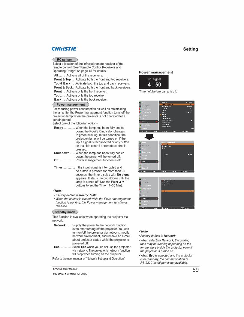
LWU505 User Manual
020-000374-01 Rev.1 (01-2011)
Note:Ready: 5 Min
Setting
Select a location of the infrared remote receiver of the remote control. See “Remote Control Receivers and Operating Range” on page 15 for details.All ........ Activate all of the receivers.Front & Top . . Activate both the front and top receivers.Top & Back . . .Activate both the top and back receivers.Front & Back . Activate both the front and back receivers.Front ... Activate only the front receiver.Top ...... Activate only the top receiver.Back .... Activate only the back receiver.
No signal
4 : 50Timer left before Lamp is off.
Power management
For reducing power consumption as well as maintaining the lamp life, the Power management function turns off the projection lamp when the projector is not operated for a certain period.Select one of the following options:Ready .............. When the lamp has been fully cooled
down, the POWER indicator changes to green blinking. In this condition, the projection lamp will be turned on if the input signal is reconnected or any button on the side control or remote control is pressed.
Shut down ...... When the lamp has been fully cooled down, the power will be turned off.
Off ................... Power management function is off.
Timer ............... If the input signal is interrupted and no button is pressed for more than 30 seconds, the timer display with No signalappears. It starts the countdown until the
buttons to set the Timer (1~30 Min).
This function is available when operating the projector via network.Network . . . .Supply the power to the network function
even after turning off the projector. You can turn on/off the projector via network, modify network environment, and receive an e-mail about projector status while the projector is powered off.
Eco............... Select Eco when you do not use the projector via network. The projector’s network function will stop when turning off the projector.
Refer to the user manual of “Network Set-up and Operation”.
Note:Network
Network
Eco
RC sensor
Power management
Standby mode
59
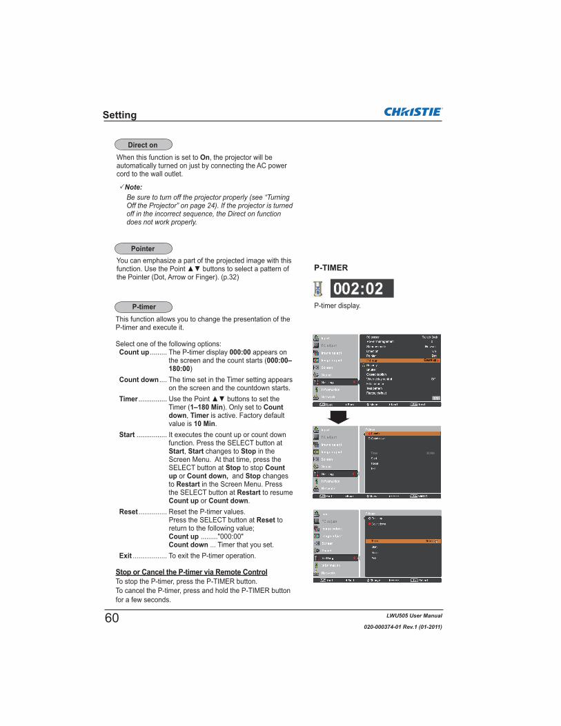
LWU505 User Manual
020-000374-01 Rev.1 (01-2011)
Setting
When this function is set to On, the projector will be automatically turned on just by connecting the AC power cord to the wall outlet.
Note:
You can emphasize a part of the projected image with this function. Use the Point buttons to select a pattern of the Pointer (Dot, Arrow or Finger). (p.32)
This function allows you to change the presentation of the P-timer and execute it.
Select one of the following options:Count up ......... The P-timer display 000:00 appears on
the screen and the count starts (000:00–180:00)
Count down .... The time set in the Timer setting appears on the screen and the countdown starts.
Timer ...............Timer (1–180 Min). Only set to Countdown, Timer is active. Factory default value is 10 Min.
Start ................ It executes the count up or count down function. Press the SELECT button at Start, Start changes to Stop in the Screen Menu. At that time, press the SELECT button at Stop to stop Countup or Count down, and Stop changes to Restart in the Screen Menu. Press the SELECT button at Restart to resume Count up or Count down.
Reset ............... Reset the P-timer values.Press the SELECT button at Reset to return to the following value;Count up ........."000:00"Count down ... Timer that you set.
Exit .................. To exit the P-timer operation.
Stop or Cancel the P-timer via Remote ControlTo stop the P-timer, press the P-TIMER button.To cancel the P-timer, press and hold the P-TIMER button for a few seconds.
P-TIMER
P-timer display.
Direct on
Pointer
P-timer
60

LWU505 User Manual
020-000374-01 Rev.1 (01-2011)
Setting
Key lockKey lock
PIN code lock
This function locks the side control and remote control buttons to prevent operation by unauthorized persons.
To unlock, use the remote control.
To unlock, use the side control.
If the side control accidentally becomes locked and you do not have the remote control nearby or there is something wrong with your remote control, contact the dealer where you purchased the projector or the service center.
This function allows you to use the Key lock and PIN code lock function to set the security for the projector operation.
This function prevents the projector from being operated by unauthorized persons and provides the following setting options for security.Off Unlocked.On 1
projector.On 2
once the power cord is disconnected; as long as the AC power cord is connected, the projector can be operated without a PIN code.
Whenever you change the PIN code lock setting or the PIN code (the four-digit number), you are required to enter the PIN code. The "1234" is set as the initial PIN code at the factory.
If you want to change the PIN code lock setting, Press the SELECT button and the PIN code dialog box appears.
PIN code lock
Security (Key lock and PIN code lock)
61

LWU505 User Manual
020-000374-01 Rev.1 (01-2011)
Setting
Enter a PIN code
Change the PIN code
Off, On 1 or On 2.Press the SELECT button to close the dialog box.
Change the PIN code lock setting
Enter a PIN code
When using side controlUse thnumber.move the red frame pointer to the next box. The number changes to . If you fix an incorrect number, use the Point
correct, and then enter the correct number.Repeat this step to complete entering a four-digit number.After entering the four-digit number, move the pointer to Set. Press the SELECT button so that you can start to operate the projector.
When using remote controlPress the Number buttons on the remote control to enter a number (p.14). When you complete entering a four-digit number, the pointer moves to “Set”. Press the SELECT button so that you can start to operate the projector.
If you enter an incorrect PIN code, PIN code and the number ( ) will turn red for a moment. Enter the correct PIN code all over again.
The PIN code can be changed to your desired four-digit PIN code
change and press the SELECT button. The Current PIN
to set the current PIN code. The New PIN code dialog box appears. Set a new PIN code, the confirmation box appears, and choose Yes to set the new PIN code.
CAUTION:WHEN YOU HAVE CHANGED THE PIN CODE,WRITE DOWN THE NEW PIN CODE IN COLUMNOF THE PIN CODE NO. MEMO ON PAGE 87, ANDKEEP IT SECURELY. IF YOU FORGET YOUR PIN CODE, THE PROJECTOR CAN NO LONGER BESTARTED.
PIN code change
buttons on the remote control to enter a number.
62

LWU505 User Manual
020-000374-01 Rev.1 (01-2011)
Shutter function is available to block out light to the screen, so that the screen can be used for the other presenters.
Prohibit the shutter operation from the remote control and the projector's side control.
both the remote control and the projector's side control.
the remote control.
the side control.
both the remote control and the projector's side control.
Protection
The Shutter Management function turns off the projection lamp when the projector is left with the shutter closed and the set time has passed away. The count-down time can be set between 5 and 480 minutes. When the count-down time has elapsed, the shutter will be opened up automatically and the lamp will be turned off to cool itself down. The SHUTTER indicator is blinking blue during this cooling-off period. When the lamp has been fully cooled down, the POWER indicator turns green lighting and the SHUTTER indicator keeps blinking. Should the ON / STAND-BY button be pressed in this condition, the projection lamp will be turned on and the SHUTTER indicator turns off.Note:
Setting
Shutter
Shutter
Management
Release keyBy using the Release function from the following options, the Shutter can be released when it stays activated (i.e. when it is closed. )Any By pressing any button on the projector's side
control or the remote control, the shutter can be released when it is closed, and meanwhile the function of the selected item will come into effect.
MUTE
SHUTTER Only by pressing the SHUTTER button on the projector’s side control or the remote control the shutter can be released when it is closed.
In addition, when the Shutter is functioning, only the following buttons are active: -- INPUT button and ON/STAND-BY button on the
projector’s side control-- INPUT 1/2/3 buttons and STAND-BY button on the
remote control
Note:
63
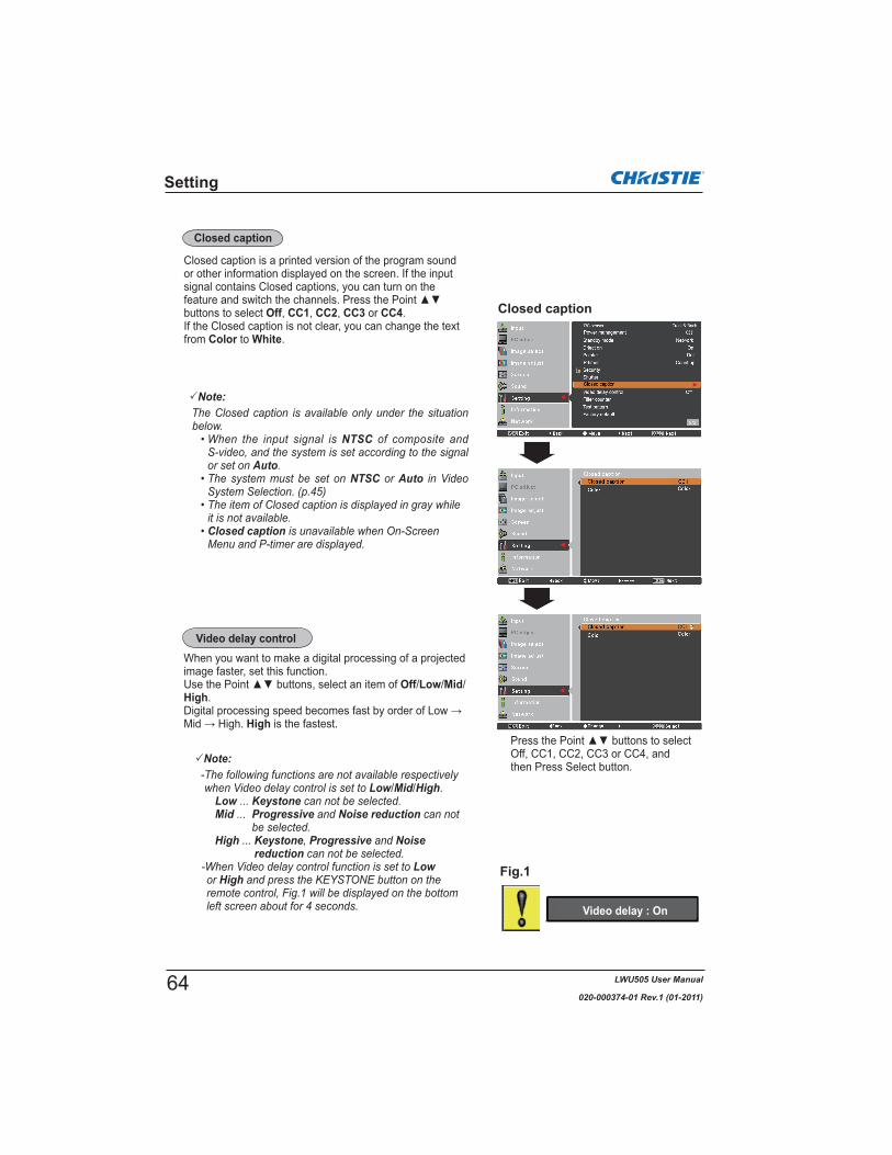
LWU505 User Manual
020-000374-01 Rev.1 (01-2011)
When you want to make a digital processing of a projected image faster, set this function.
Off/Low/Mid/High.
High is the fastest.
Video delay control
Fig.1
Note:
Low/Mid/High.Low KeystoneMid Progressive Noise reduction
High Keystone Progressive Noisereduction
Low High
Video delay : On
Setting
Closed caption
Closed caption is a printed version of the program sound or other information displayed on the screen. If the input signal contains Closed captions, you can turn on the feature and switch the channels. Press the Point buttons to select Off, CC1, CC2, CC3 or CC4.If the Closed caption is not clear, you can change the text from Color to White.
Closed caption
Note:
NTSC
AutoNTSC Auto
Closed caption
Press the Point buttons to select Off, CC1, CC2, CC3 or CC4, and then Press Select button.
64
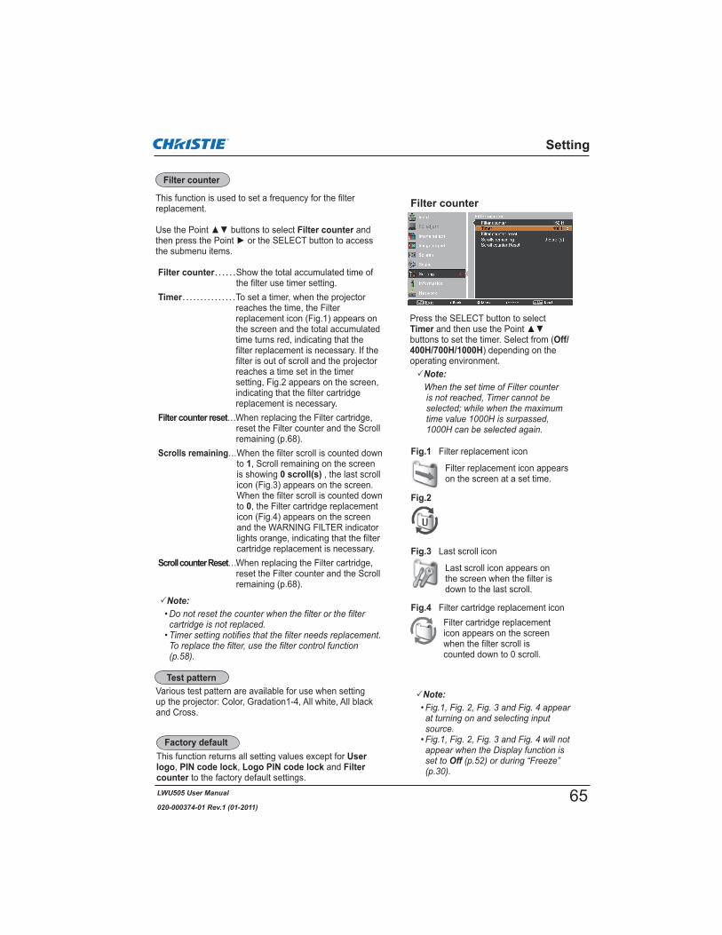
LWU505 User Manual
020-000374-01 Rev.1 (01-2011)
This function returns all setting values except for Userlogo, PIN code lock, Logo PIN code lock and Filter counter to the factory default settings.
Various test pattern are available for use when setting up the projector: Color, Gradation1-4, All white, All black and Cross.
Filter replacement icon appears on the screen at a set time.
Note:
Fig.1 Filter replacement icon
Filter cartridge replacement icon appears on the screen when the filter scroll is counted down to 0 scroll.
Fig.4 Filter cartridge replacement icon
Note:
Off
Last scroll icon appears on the screen when the filter is down to the last scroll.
Fig.3 Last scroll icon
Setting
This function is used to set a frequency for the filter replacement.
Filter counter and
the submenu items.
Filter counter Show the total accumulated time of the filter use timer setting.
Timer To set a timer, when the projector reaches the time, the Filter replacement icon (Fig.1) appears on the screen and the total accumulated time turns red, indicating that the filter replacement is necessary. If the filter is out of scroll and the projector reaches a time set in the timer setting, Fig.2 appears on the screen, indicating that the filter cartridge replacement is necessary.
Filter counter reset replacing the Filter cartridge, reset the Filter counter and the Scroll remaining (p.68).
Scrolls remaining When the filter scroll is counted down to 1, Scroll remaining on the screen is showing 0 scroll(s) , the last scroll icon (Fig.3) appears on the screen.When the filter scroll is counted down to 0, the Filter cartridge replacement icon (Fig.4) appears on the screen and the WARNING FILTER indicator lights orange, indicating that the filter cartridge replacement is necessary.
Scroll counter Reset When replacing the Filter cartridge, reset the Filter counter and the Scroll remaining (p.68).
Fig.2
Filter counter
Press the SELECT button to select Timerbuttons to set the timer. Select from (Off/400H/700H/1000H) depending on the operating environment.
Filter counter
Test pattern
Factory default
Note:
65

LWU505 User Manual
020-000374-01 Rev.1 (01-2011)
Filter prevents dust from accumulating on the optical elements inside the projector. Should the filter becomes clogged with dust particles, it will reduce cooling fans’ effectiveness and may result in internal heat buildup and adversely affect the life of the projector. This projector has an electrically operated filter which helps you to replace the filter easily. The projector monitors the condition of the filter at all time and replaces a filter with a new one automatically when it detects the clogging. If the projector reaches a time set in the timer setting (p.65), a Filter replacement icon (Fig.1) appears on the screen and the WARNING FILTER indicator on the top panel lights up (p.81). When you see this icon, replace the filter as soon as possible (pp.30, 58). If the filter is out of scroll and the projector reaches a time set in the timer setting, Fig. 2 appears on the screen, indicating that the filter cartridge replacement is necessary.
When the filter scroll is counted down to 0, the Last scroll icon (Fig.3) appears on the screen, indicating that there is one scroll left in the filter cartridge (p.65).
If the projector detects that the filter is clogged and no scroll is left in the filter cartridge, a Filter cartridge replacement icon (Fig. 4) appears on the screen and the WARNING FILTER indicator on the top panel lights up (p.81). When you see this icon, replace the filter cartridge (p.67) and reset the Filter counter (p.68) and the Scroll counter (p.68).
When the filter is being scrolled using the remote control (p.30) or the Filter control function in the setting menu (p.58), a Filter replacement icon and Please wait...message (Fig.5) appear on the screen and the WARNING FILTER indicator blinks slow (approx. 2 seconds ON, 2 seconds OFF) (p.79).
The WARNING FILTER indicator blinks fast when the projector detects an abnormal condition, the filter cartridge is not installed properly, or the filter scroll is not working properly (p.81).
Fig.1 Filter replacement icon
Fig.4 Filter cartridge replacement icon
Fig.3 Last scroll icon
Maintenance and Care
Note:
Off
Fig.5 Filter replacement icon and Please wait... message.
Fig.2
Filter Instructions
66
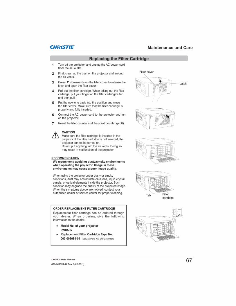
LWU505 User Manual
020-000374-01 Rev.1 (01-2011)
Turn off the projector, and unplug the AC power cord from the AC outlet.
First, clean up the dust on the projector and around the air vents.
1
2
latch and open the filter cover.3
Put the new one back into the position and close the filter cover. Make sure that the filter cartridge is properly and fully inserted.
5
CAUTIONMake sure the filter cartridge is inserted in the projector. If the filter cartridge is not inserted, the projector cannot be turned on. Do not put anything into the air vents. Doing so may result in malfunction of the projector.
4
Reset the filter counter and the scroll counter (p.68).
6
Filter cover
Pull out the filter cartridge. When taking out the filter cartridge, put your finger on the filter cartridge’s tab and then pull.
Latch
Filtercartridge
Tab
RECOMMENDATIONWe recommend avoiding dusty/smoky environments when operating the projector. Usage in these environments may cause a poor image quality.
When using the projector under dusty or smoky conditions, dust may accumulate on a lens, liquid crystal panels, or optical elements inside the projector. Such condition may degrade the quality of the projected image.When the symptoms above are noticed, contact your authorized dealer or service center for proper cleaning.
ORDER REPLACEMENT FILTER CARTRIDGEReplacement filter cartridge can be ordered through your dealer. When ordering, give the following information to the dealer.
Model No. of your projector LWU505
Replacement Filter Cartridge Type No. 003-003084-01 (Service Parts No. 610 346 9034)
Connect the AC power cord to the projector and turn on the projector.
7
Maintenance and Care
Replacing the Filter Cartridge
67
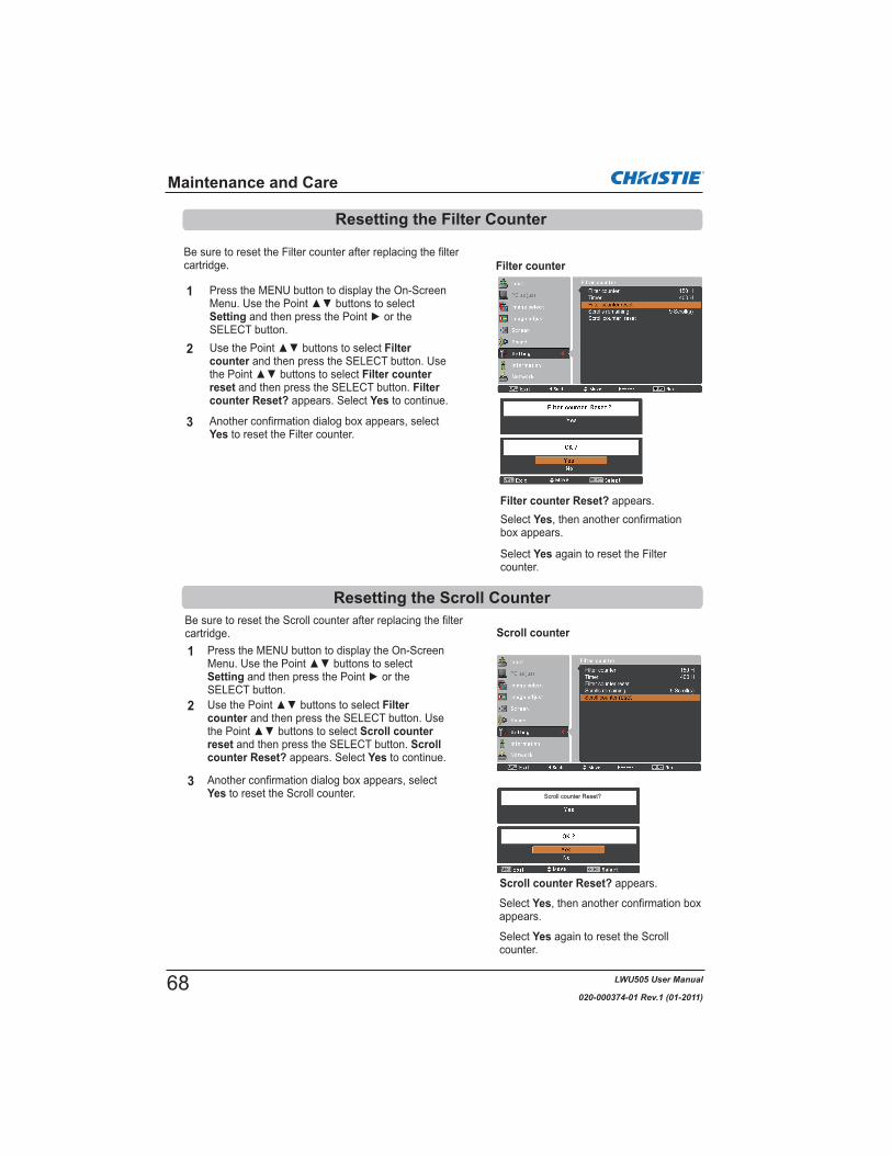
LWU505 User Manual
020-000374-01 Rev.1 (01-2011)
Be sure to reset the Scroll counter after replacing the filter cartridge.
Press the MENU button to display the On-Screen
SettingSELECT button.
Filtercounter and then press the SELECT button. Use
Scroll counter reset and then press the SELECT button. Scrollcounter Reset? appears. Select Yes to continue.
1
2
Scroll counter
3 Another confirmation dialog box appears, select Yes to reset the Scroll counter.
Filter counter
Maintenance and Care
Be sure to reset the Filter counter after replacing the filter cartridge.
Press the MENU button to display the On-Screen
SettingSELECT button.
Filtercounter and then press the SELECT button. Use
Filter counter reset and then press the SELECT button. Filtercounter Reset? appears. Select Yes to continue.
1
2
Filter counter Reset? appears.Select Yes, then another confirmation box appears.
Select Yes again to reset the Filter counter.
Another confirmation dialog box appears, select Yes to reset the Filter counter.
3
Scroll counter Reset? appears.
Select Yes, then another confirmation box appears.
Select Yes again to reset the Scroll counter.
Scroll counter Reset?
Resetting the Filter Counter
Resetting the Scroll Counter
68

LWU505 User Manual
020-000374-01 Rev.1 (01-2011)
Turn off the projector and unplug the AC power cord. Let the projector cool for at least 45 minutes.Loosen the screws and open the lamp cover. Loosen 3 screws of the lamp and pull out the lamp by using the built in handle.
1
3 Replace the lamp with a new one. Make sure that the lamp is properly and fully inserted.
4
2
Connect the AC power cord to the projector and turn on the projector.
Follow these steps to replace the lamp.
5
Note:
For continued safety, replace with a lamp of the same type. Do not drop the lamp or touch the glass bulb! The glass can shatter and may cause injury.
Allow a projector to cool for at least 45 minutes before you open the lamp cover. The inside of the projector can become very hot.
CAUTION
CAUTION
When the projection lamp of the projector reaches its end of life, the Lamp replacement icon appears on the screen and LAMP REPLACE indicator lights orange. Replace the lamp with a new one promptly. The timing when the LAMP REPLACE indicator should light is depending on the lamp mode.
Top Panel
LAMP REPLACE indicator
Lamp replacement icon
Note:
Off
Close the lamp cover and secure the screw.
Maintenance and Care
Lamp Replacement
When replacing the lamp because it has stopped illuminating, there is a possibility that the lamp may be broken.If replacing the lamp of a projector which has been installed on the ceiling, you should always assume that the lamp is broken, and you should stand to the side of the lamp cover, not underneath it. Remove the lamp cover gently. Small pieces of glass may fall out when the lamp cover is opened.If pieces of glass get into your eyes or mouth, seek medical advice immediately.
CAUTION
Lamp
Handle
Lamp cover
Screw
NewLamp
Screws
69

LWU505 User Manual
020-000374-01 Rev.1 (01-2011)
ORDER REPLACEMENT LAMPReplacement lamp can be ordered through your dealer. When ordering, give the following information to the dealer.
Model No. of your projector : LWU505Replacement Lamp Type No. : 003-120507-01
(Service Parts No.610 346 9607)
Maintenance and Care
This projector uses a high-pressure lamp which must be handled carefully and properly. Improper handling may result in accidents, injury, or create a fire hazard.
is no guarantee of the same lifetime for each lamp. Some lamps may fail or terminate their lifetime in a shorter period of time than other similar lamps.
indicator lights up, replace the lamp with a new one IMMEDIATELY after the projector has cooled down. (Follow carefully the instructions in the Lamp Replacement section of this manual.) Continuous use of the lamp with the LAMP REPLACE indicator lighted may increase the risk of lamp explosion.
as its lifetime draws to an end. Risk of explosion may differ according to the environment or conditions in which the projector and lamp are being used.
IF A LAMP EXPLODES, THE FOLLOWING SAFETY PRECAUTIONS SHOULD BE TAKEN.If a lamp explodes, disconnect the projector’s AC plug from the AC outlet immediately. Contact an authorized service center for a checkup of the unit and replacement of the lamp. Additionally, check carefully to ensure that there are no broken shards or pieces of glass around the projector or coming out from the cooling air circulation holes. Any broken shards found should be cleaned up carefully. No one should check the inside of the projector except those who are authorized trained technicians and who are familiar with projector service. Inappropriate attempts to service the unit by anyone, especially those who are not appropriately trained to do so, may result in an accident or injury caused by pieces of broken glass.
LAMP HANDLING PRECAUTIONS
70

LWU505 User Manual
020-000374-01 Rev.1 (01-2011)
Unplug the AC power cord before cleaning.
Gently wipe the projection lens with a cleaning cloth that contains a small amount of non-abrasive camera lens cleaner, or use a lens cleaning paper or commercially available air blower to clean the lens.
Avoid using an excessive amount of cleaner. Abrasive cleaners, solvents, or other harsh chemicals might scratch the surface of the lens.
Unplug the AC power cord before cleaning.
Gently wipe the projector body with a soft dry cleaning cloth. When the cabinet is heavily soiled, use a small amount of mild detergent and finish with a soft dry cleaning cloth. Avoid using an excessive amount of cleaner. Abrasive cleaners, solvents, or other harsh chemicals might scratch the surface of the cabinet.
When the projector is not in use, put the projector in an appropriate carrying case to protect from dust and scratches.
Maintenance and Care
Cleaning the Projection Lens
Cleaning the Projector Cabinet
Do not use any flammable solvents or air sprays on the projector and in its vicinity. The explosion or fire hazard may occur even after the AC power cord is unplugged because the temperature inside the projector is extremely high due to the lamps. In addition, there is a risk that the internal parts may be damaged not only by the flammable air spray but also by the cold air.
CAUTION
71

LWU505 User Manual
020-000374-01 Rev.1 (01-2011)
The WARNING indicators show the state of the function which protects the projector. Check the state of the WARNING indicators and the POWER indicator to take proper maintenance.
The projector is shut down and the WARNING TEMP.indicator is blinking red.When the temperature inside the projector reaches acertain level, the projector will be automatically shut down to protect the inside of the projector. The POWER indicator is blinking while the projector is being cooled down. When the projector has cooled down enough (to its normal operating temperature), it can be turned on again by pressing the ON/STAND-BY button.
Note:
Then check the matters below:– Did you provide appropriate space for the projector to be
ventilated? Check the installing condition to see if the air vents of the projector are not blocked.
– Has the projector been installed near an Air-Conditioning/ Heating Duct or Vent? Move the installation of the projector away from the duct or vent.
– Is the filter clean? Replace the filter with a new one.
The projector is shut down and the LAMP indicator is lighting and other indicators are blinking.When the projector detects an abnormal condition, it will be automatically shut down to protect the inside of the projector and the LAMP indicator lights on and other indicators blink. In this case, unplug the AC power cord and plug it, and then turn on the projector once again to verify operation. If the projector cannot be turned on and these indicators are still lighting and blinking, unplug the AC power cord and contact the service center.
CAUTIONDO NOT LEAVE THE PROJECTOR WITH THE AC POWER CORD CONNECTED UNDER AN ABNORMAL CONDITION. IT MAY RESULT IN FIRE OR ELECTRIC SHOCK.
Top Panel
LAMP indicator lights on and other indicators blink.
Top Panel
WARNING TEMP.blinking red
Maintenance and Care
Warning Indicators
72

LWU505 User Manual
020-000374-01 Rev.1 (01-2011)
Before calling your dealer or service center for assistance, check the items below once again.1. Make sure you have properly connected the projector to peripheral equipment as described on pages
19-21.2. Check the cable connection. Make sure that all computers, video equipment, and power cords are
properly connected.3. Make sure that all power is switched on.4. If the projector still does not produce an image, restart your computer.5. If an image still does not appear, disconnect the projector from your computer and check your computer
monitor’s display. A problem may be noticed with your graphics controller rather than with the projector. (When you reconnect the projector, be sure to turn the computer and monitor off before you turn on the projector. Turn on equipment in the order of the projector and computer.)
6. If a problem still persists, check the following solutions.
Appendix
Problem: Solutions
No power.
– Plug the power cord of the projector into the AC outlet.– Wait until the POWER indicator stops blinking to turn on the projector again. (See
page 23)– Check the WARNING TEMP. indicator. If the WARNING TEMP. indicator is blinking,
the projector cannot be turned on. (See page 72)– Unlock the Key lock function for the projector. (See page 61)– See if the filter cartridge is inserted. (See page 67)– Check the projection lamp. (See pages 69-70)
PIN code dialog box appears at start-up.
– PIN code lock is being set. Enter a PIN code; the “1234” or numbers you have set. (See pages 23, 61-62)
The initial display is not shown.
– Make sure Off or Countdown Off is not chosen at Display function. (See “Setting” section on page 52)
The initial display is not same with the default one.
– Make sure User or Off is not chosen at Logo select function. (See “Setting” section on page 52)
When the projector is on and you press the input button, an icon other than the Lamp mode icon appears.
– That is the Filter warning icon. (See page 66)
An icon other than Input mode or Lamp mode icon appears.
– That is the Lamp replacement icon or the Filter warning icon. (See pages 66,69)
No image.
– Check the connection between your computer or video equipment and the projector.– See if the input signal is correctly output from your computer. Some laptop
computers may need to be changed the setting for monitor output when connected to the projector. See your computer’s instruction manual for the setting.
– It takes about 30 seconds to display an image after turning on the projector.– See if the selected system is corresponding with your computer or video equipment.– Select correct input source once again through menu operation. (See pages 33-35)– Make sure the temperature is not out of Operating Temperature
– Make sure that the shutter is opened. (pp.27, 63)
appears on the screen
– End of lamp life is approaching. Replace the lamp with a new one promptly. (See page 69)
Troubleshooting
73
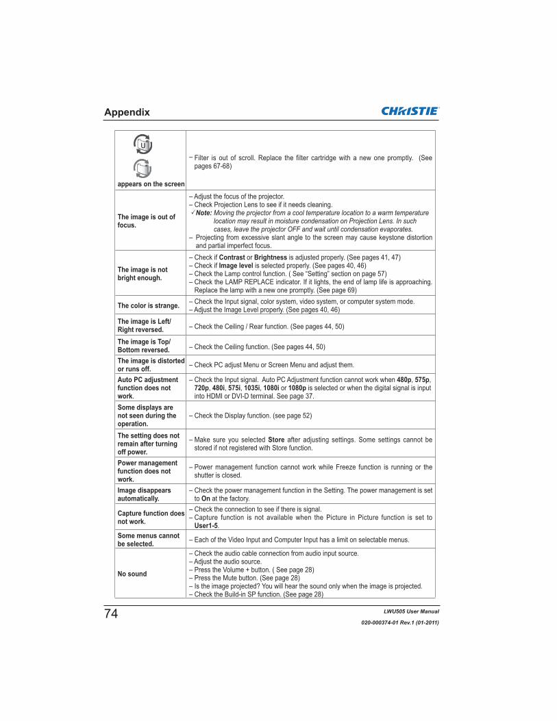
LWU505 User Manual
020-000374-01 Rev.1 (01-2011)
appears on the screen
– Filter is out of scroll. Replace the filter cartridge with a new one promptly. (See pages 67-68)
The image is out of focus.
– Adjust the focus of the projector.– Check Projection Lens to see if it needs cleaning.
Note:
– Projecting from excessive slant angle to the screen may cause keystone distortion and partial imperfect focus.
The image is not bright enough.
– Check if Contrast or Brightness is adjusted properly. (See pages 41, 47) – Check if Image level is selected properly. (See pages 40, 46)– Check the Lamp control function. ( See “Setting” section on page 57)– Check the LAMP REPLACE indicator. If it lights, the end of lamp life is approaching.
Replace the lamp with a new one promptly. (See page 69)
The color is strange. – Check the Input signal, color system, video system, or computer system mode.– Adjust the Image Level properly. (See pages 40, 46)
The image is Left/Right reversed. – Check the Ceiling / Rear function. (See pages 44, 50)
The image is Top/Bottom reversed. – Check the Ceiling function. (See pages 44, 50)
The image is distorted or runs off. – Check PC adjust Menu or Screen Menu and adjust them.
Auto PC adjustment function does not work.
– Check the Input signal. Auto PC Adjustment function cannot work when 480p, 575p,720p, 480i, 575i, 1035i, 1080i or 1080p is selected or when the digital signal is input into HDMI or DVI-D terminal. See page 37.
Some displays are not seen during the operation.
– Check the Display function. (see page 52)
The setting does not remain after turning off power.
– Make sure you selected Store after adjusting settings. Some settings cannot be stored if not registered with Store function.
Power management function does not work.
– Power management function cannot work while Freeze function is running or the shutter is closed.
Image disappears automatically.
– Check the power management function in the Setting. The power management is set to On at the factory.
Capture function does not work.
– Check the connection to see if there is signal.– Capture function is not available when the Picture in Picture function is set to
User1-5.Some menus cannot be selected. – Each of the Video Input and Computer Input has a limit on selectable menus.
No sound
– Check the audio cable connection from audio input source.– Adjust the audio source.– Press the Volume + button. ( See page 28)– Press the Mute button. (See page 28)– Is the image projected? You will hear the sound only when the image is projected.– Check the Build-in SP function. (See page 28)
Appendix
74

LWU505 User Manual
020-000374-01 Rev.1 (01-2011)
WARNING: High voltages are used to operate this projector. Do not attempt to open the cabinet.If problems still persist after following all operating instructions, contact the dealer where you purchased the projector or the service center. Specify the model number and explain about the problem. We will advise you how to obtain service.
Appendix
The shutter does not work. – Check "Protection" or "Release key" of the Shutter function. (See p.63)
The power is turned off automatically.
– Power management function runs by initial setting. Check “Setting” section on page 59.
– When the filter cartridge replacement icon keeps appearing on the screen at turning on the projector for some time and no action is taken to replace the filter cartridge, the projector will be automatically shut down in 3 minutes after turning on to protect the projector. (See pages 66, 81)
– Do not cover the ventilation slots on the projector. (See pages 4, 6)– Projector may be used in high ambient temperature environment. Make
You cannot operate with the side control.
– If the side control is locked at "Key lock" under "Security" of Setting menu, the side control is not available. Please check “Setting” section on page 61.
The Remote Control does not work.
– Check the batteries.– Check if the RC sensor is set properly. (See page 59)– Make sure no obstruction is between the projector and remote control.– Make sure you are not too far from the projector when using the remote
control.Maximum operating range is 16.4’ (5m). (See page 15)– Make sure that the remote control code conforms to the projector’s code.
(See “Setting” section on page 58.)– Unlock the Key lock function for the remote control. (See page 61)– Wireless remote control does not work when the remote control cable is
connected to the projector. (See page 15)– Check if the ON/OFF switch on the remote control is set to “ON.”– Make sure that the simple mode in the remote control function is set to Off
(See page 58).
Wireless mouse function does not work.
– Check the cable connection between the projector and your computer. (See pages 19, 32)
– Check the mouse setting on your computer.– Turn on the projector before you turn on the computer.
Indicators blink or light.
– Check the status of the projector with referring to “Indicators and projector condition” on pages 79-81.
appears on the screen– Your operation is invalid. Operate correctly.
Unable to unlock the Logo PIN code lock, Security key lock or Security PIN code lock.
– Contact the dealer where you've purchased the projector or the service center.
Forget the Logo PIN code or Security PIN code.
– Contact the dealer where you've purchased the projector or the service center.
appears on the screen
– The projector detects an abnormal condition. Unplug the AC power cord and contact the dealer where you purchased the projector or the service center.
75

LWU505 User Manual
020-000374-01 Rev.1 (01-2011)
Mode 10
Input RGB (PC analog)
Y, Pb/Cb,Pr/Cr
RGB (Scart)
HDMI
Network
Video
RGBVideoY, Pb/Cb,Pr/CrS-video
Input 3
Input
H-sync freq.V-sync freq.
Information
ScreenLanguageLamp status
Power management
Remote control
Note:
Appendix
Volume
Mute On/Off
Sound 0-63Built-in SP
PIN code lockKey lock
SERIAL NO.
Network will be displayed only when an optional Network unit is attached.
*
*
Input 1
Input 2
Lamp counterFilter counter
Simple mode
On/Off
System (1) Mode 1
System displayed in the System Menu varies depending on the input signal.
SVGA 1SVGA 2SVGA 3
Image adjust ContrastBrightness
Color temp.
Red
Gamma
Store
0–630–63
0–63
0–15
Image 1
Image 10
Reset Yes/No
Sharpness 0–31
GreenBlue
0–630–63
MidLowXLow
AdjHigh
Offset Red/Green/Blue
Image select Dynamic
RealImage 1
Image 10
PC adjust Auto PC adj.Fine sync.Total dotsPosition HPosition VCurrent modeClampDisplay area - HDisplay area - VResetMode freeStore
0–31
Yes/No
Mode 1
Mode 10
Menu TreeComputer Input/HDMI Input/Video Input
Computer Input
Image adjust
Image select
PC adjust
Sound
Information
Input
Shutter management
Standard
SVGA1
Iris On/Off
RGB (PC digital)RGB (AV HDCP)
System
76

LWU505 User Manual
020-000374-01 Rev.1 (01-2011)
Note:
System (2) AutoPALSECAMNTSCNTSC 4.43PAL-MPAL-N
System (3) Auto
1080i1035i720p575p480p575i480i
Image select
Cinema
Appendix
Screen Normal
Wide(16:9)Full
Zoom
RearCeiling
On/OffOn/Off
Custom adj.H & VScale
Position
H / VOn/OffH / V
CommonReset
Reset
Screen
Digital zoom +Digital zoom -
Video Input
Image select
Screen
Image adjust ContrastBrightness
Color temp.
Red
Gamma
Store
0–630–63
0–63
0–15
Image 1Image 10
Reset Yes/No
Sharpness 0–31
GreenBlue
0–630–63
MidLowXLow
AdjHigh
Offset Red/Green/Blue
Image adjust
Color 0–63Tint 0–63
Noise reduction Off/OnProgressive Off/On/Film
Custom
DynamicStandard
Image 1Image 10
Screen NormalFullWide(16:9)
Natural wide
Rear
Keystone
Ceiling
Corner correctionStandard
On/OffOn/Off
Custom adj. Scale
Position
H / VOn/OffH / V
CommonReset
Reset
Custom
Screen aspect
Zoom
True
HDMI Input/Video Input
1080p
Default(16:10)/16:9/4:3
Corner patternStore
Natural
Screen aspect Default(16:10)/16:9/4:3
Iris On/Off
H & V
KeystoneCorner correctionStandard
Corner patternStore
77
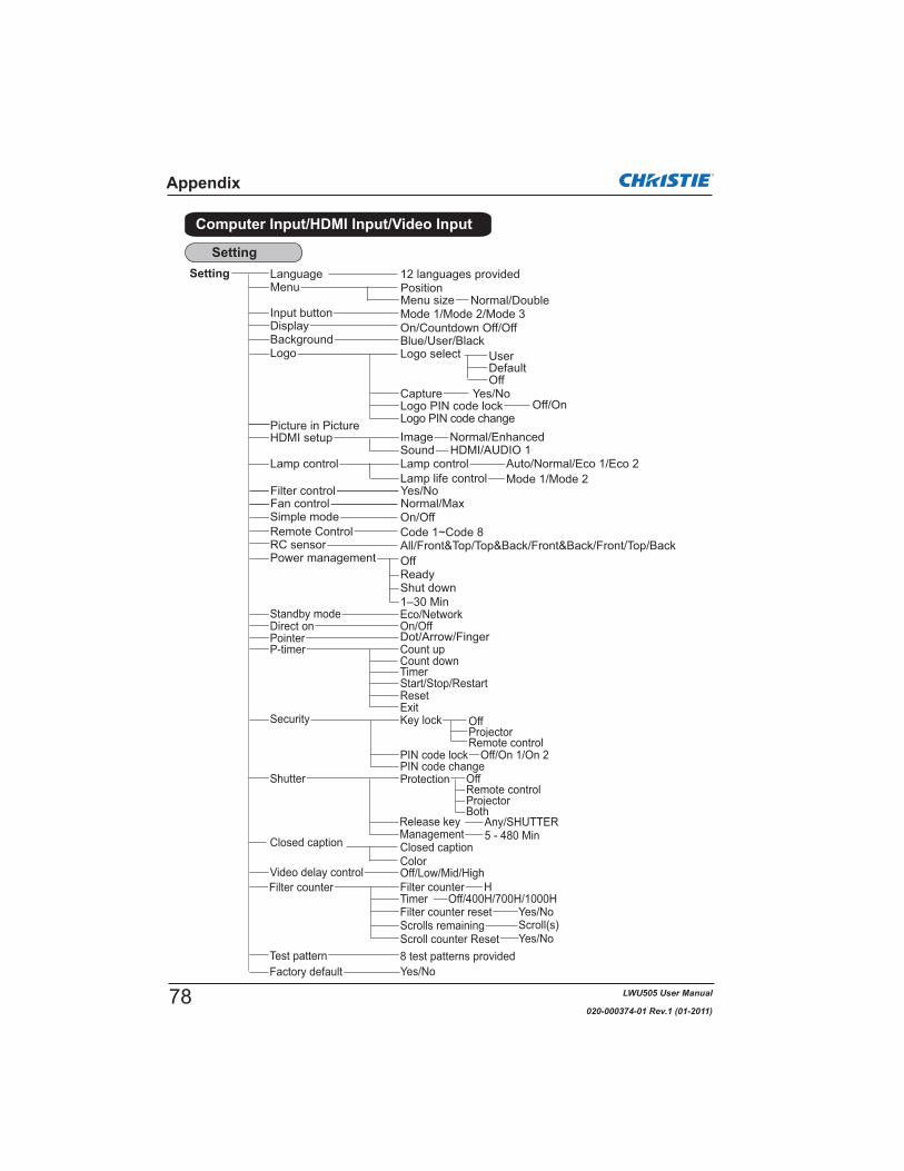
LWU505 User Manual
020-000374-01 Rev.1 (01-2011)
Setting Language
Fan control
Blue/User/Black
Yes/No
12 languages providedMenu
Lamp control
Filter control
All/Front&Top/Top&Back/Front&Back/Front/Top/Back
Normal/Max
Power management
Background
RC sensor
ReadyOff
Shut down1–30 Min
On/OffDirect onPointer
On/Countdown Off/OffDisplay
Remote Control
Dot/Arrow/Finger
Appendix
Yes/No
Management
Remote controlProjector
5 - 480 Min
Code 1~Code 8On/Off
Computer Input/HDMI Input/Video Input
Logo select
Off
User
Capture Yes/NoOff/On
Logo PIN code changeLogo PIN code lock
DefaultLogo
Input button Mode 1/Mode 2/Mode 3
Lamp life controlLamp control Auto/Normal/Eco 1/Eco 2
Mode 1/Mode 2
Simple mode
Eco/NetworkStandby mode
P-timer Count up
TimerStart/Stop/Restart
Count down
Security OffProjectorRemote control
Key lock
Off/On 1/On 2PIN code changePIN code lock
HFilter counter
Yes/NoOff/400H/700H/1000H
Filter counterTimerFilter counter reset
Yes/NoScroll(s)Scrolls remaining
Scroll counter Reset8 test patterns providedTest pattern
Setting
ResetExit
SoundImageHDMI setup
Closed caption Closed captionColorOff/Low/Mid/HighVideo delay control
Picture in Picture
Protection
Factory default
Shutter Off
Both
PositionMenu size Normal/Double
Release key Any/SHUTTER
Normal/EnhancedHDMI/AUDIO 1
78

LWU505 User Manual
020-000374-01 Rev.1 (01-2011)
Check the indicators for the projector condition.
IndicatorsProjector ConditionPOWER
greenLAMP
red
WARNINGTEMP.
red
WARNINGFILTERorange
SHUTTERblue
LAMPREPLACE
orange
The projector is off. (The AC power cord is unplugged.)
The projector is in stand-by mode. Press the ON/STAND-BY button to turn on the projector.
The projector is operating normally.(The shutter is open)
The projector is operating normally.(The shutter is closed)
The projector is preparing for stand-by or the projection lamp is being cooled down. The projector cannot be turned on until cooling is completed and the POWER indicator lights green.
The projection lamp is being cooled down in the Power management mode.
The projector is in the Power management mode.
The projection lamp is being cooled down in the Shutter management mode.
The projector is in the Shutter management mode. Press the ON/STAND-BY button to turn on the projector.
The filter is scrolled using the FILTER button on the remote control or the Filter control function in the setting menu. When the filter is being scrolled, the Filter replacement icon and Please wait... message (Fig. 1) appear on the screen for about 30 seconds.
The projector is operating normally.
(approx. 1 second ON, 1 second OFF)
ON, 2 seconds OFF)
Appendix
Fig.1 Filter replacement icon and Please wait....
rate (blue and dim red) (approx. 1 second ON, 1 second OFF)
(approx. 0.5 seconds ON, 0.5 seconds OFF)
ON, 0.5 seconds OFF)
Indicators and Projector Condition
79

LWU505 User Manual
020-000374-01 Rev.1 (01-2011)
The projector is detecting abnormal condition.
IndicatorsProjector ConditionPOWER
greenLAMP
red
WARNINGTEMP.
red
WARNINGFILTERorange
SHUTTERblue
LAMPREPLACE
orange
The temperature inside the projector is elevated close to the abnormally high level.
The temperature inside the projector is abnormally high. The projector cannot be turned on. When the projector is cooled down enough and the temperature returns to normal, the POWER indicator lights green and the projector can be turned on. (The WARNING TEMP. indicator keeps blinking.) Check and replace the filter.The projector has been cooled down enough and the temperature returns to normal. When turning on the projector, the WARNING TEMP. indicator stops blinking. Check and replace the filter.
The lamp cannot light up. (The projector is preparing for stand-by or the projection lamp is being cooled down. The projector cannot be turned on until cooling is completed.)The lamp cannot light up. (The lamp has been cooled down enough and the projector is in stand-by mode and ready to be turned on with the ON/STAND-BY button.)
The lamp has been used overtime. Replace the lamp immediately.
When the filter detects clogging, reaches a time set in the timer setting or runs out of the filter scroll, the WARNING FILTER indicator lights orange. When this indicator lights orange, replace the filter or the filter cartridge with a new one promptly. Reset the Filter counter and Scroll counter after replacing the filter cartridge (p.68).
Appendix
When the projection lamp reaches its end of life, the LAMP REPLACE indicator lights orange. When this indicator lights orange, replace the projection lamp with a new one promptly (p.69).
WARNING FILTER
LAMP REPLACE
80

LWU505 User Manual
020-000374-01 Rev.1 (01-2011)
The projector is detecting abnormal condition.
IndicatorsProjector ConditionPOWER
greenLAMP
red
WARNINGTEMP.
red
WARNINGFILTERorange
SHUTTER blue
LAMPREPLACE
orange
If the Filter counter reaches a time set in the timer setting, a Filter replacement icon (Fig.2) will appear on the screen and the WARNING FILTER indicator on the top panel will light up. Replace the filter as soon as possible. If the filter is out of scroll and the projector reaches a time set in the timer setting, Fig. 3 will appear on the screen and the WARNING FILTER indicator will light up. Replace the filter cartridge as soon as possible.If the filter is clogged and no scroll is left in the filter cartridge, a Filter cartridge replacement icon (Fig.4) will appear on the screen and the WARNING FILTER indicator will light up. Replace the filter cartridge as soon as possible.
Note:
Off
The filter cartridge is not installed in the projector. Check the filter compartment to see if the filter cartridge is installed in the projector. When the filter cartridge is installed and the indicators continue to light and blink, read the column below.
The projector detects an abnormal condition and cannot be turned on. Unplug the AC power cord and plug it again to turn on the projector. If the projector is turned off again, unplug the AC power cord and contact the dealer or the service center. Do not leave the projector on. It may cause an electric shock or a fire hazard.
The shutter is out of control.
The shutter is out of control. (The projector is in the cooling mode.)
The shutter is out of control. (The projector is in the stand-by mode.) In that case, contact the service center immediately.
Fig.2 Filter replacement icon
Fig.4 Filter cartridge replacement icon
Fig.3
Appendix
81

LWU505 User Manual
020-000374-01 Rev.1 (01-2011)
ON-SCREENDISPLAY
RESOLUTION H-Freq.(kHz)
V-Freq.(Hz)
VGA 1 640x480 31.470 59.880VGA 2 720x400 31.470 70.090VGA 3 640x400 31.470 70.090VGA 4 640x480 37.860 74.380VGA 5 640x480 37.860 72.810VGA 6 640x480 37.500 75.000VGA 7 640x480 43.269 85.000
MAC LC13 640x480 34.970 66.600MAC 13 640x480 35.000 66.670
480p 640x480 31.470 59.880575p 768x575 31.250 50.000575i 768x576
(Interlace)15.625 50.000
480i 640x480(Interlace)
15.734 60.000SVGA 1 800x600 35.156 56.250SVGA 2 800x600 37.880 60.320SVGA 3 800x600 46.875 75.000SVGA 4 800x600 53.674 85.060SVGA 5 800x600 48.080 72.190SVGA 6 800x600 37.900 61.030SVGA 7 800x600 34.500 55.380SVGA 8 800x600 38.000 60.510SVGA 9 800x600 38.600 60.310
SVGA 10 800x600 32.700 51.090SVGA 11 800x600 38.000 60.510MAC 16 832x624 49.720 74.550XGA 1 1024x768 48.360 60.000XGA 2 1024x768 68.677 84.997XGA 3 1024x768 60.023 75.030XGA 4 1024x768 56.476 70.070XGA 5 1024x768 60.310 74.920XGA 6 1024x768 48.500 60.020XGA 7 1024x768 44.000 54.580XGA 8 1024x768 63.480 79.350XGA 9 1024x768
(Interlace)36.000 87.170
XGA 10 1024x768 62.040 77.070XGA 11 1024x768 61.000 75.700XGA 12 1024x768
(Interlace)35.522 86.960
XGA 13 1024x768 46.900 58.200XGA 14 1024x768 47.000 58.300XGA 15 1024x768 58.030 72.000MAC 19 1024x768 60.240 75.080SXGA 1 1152x864 64.200 70.400SXGA 2 1280x1024 62.500 58.600SXGA 3 1280x1024 63.900 60.000SXGA 4 1280x1024 63.340 59.980SXGA 5 1280x1024 63.740 60.010SXGA 6 1280x1024 71.690 67.190SXGA 7 1280x1024 81.130 76.107SXGA 8 1280x1024 63.980 60.020SXGA 9 1280x1024 79.976 75.025
SXGA 10 1280x960 60.000 60.000SXGA 11 1152x900 61.200 65.200SXGA 12 1152x900 71.400 75.600
ON-SCREENDISPLAY
RESOLUTION H-Freq.(kHz)
V-Freq.(Hz)
SXGA 13 1280x1024(Interlace)
50.000 86.000SXGA 14 1280x1024
(Interlace)50.000 94.000
SXGA 15 1280x1024 63.370 60.010SXGA 16 1280x1024 76.970 72.000SXGA 17 1152x900 61.850 66.000SXGA 18 1280x1024
(Interlace) 46.430 86.700SXGA 19 1280x1024 63.790 60.180SXGA 20 1280x1024 91.146 85.024SXGA+ 1 1400x1050 63.970 60.190SXGA+ 2 1400x1050 65.350 60.120SXGA+ 3 1400x1050 65.120 59.900SXGA+ 4 1400x1050 64.030 60.010SXGA+ 5 1400x1050 62.500 58.600SXGA+ 6 1400x1050 64.744 59.948SXGA+ 7 1400x1050 65.317 59.978MAC 21 1152x870 68.680 75.060
MAC 1280x960 75.000 75.080MAC 1280x1024 80.000 75.080
WXGA 1 1366x768 48.360 60.000WXGA 2 1360x768 47.700 60.000WXGA 3 1376x768 48.360 60.000WXGA 4 1360x768 56.160 72.000WXGA 6 1280x768 47.776 59.870WXGA 7 1280x768 60.289 74.893WXGA 8 1280x768 68.633 84.837WXGA 9 1280x800 49.600 60.050WXGA 10 1280x800 41.200 50.000WXGA 11 1280x800 49.702 59.810WXGA 12 1280X800 63.980 60.020WUXGA 1 1920x1200 74.556 59.885WUXGA 2 1920x1200 74.038 59.950WSXGA +1 1680x1050 65.290 59.954WXGA +1 1440x900 55.935 59.887WXGA +2 1440x900 74.918 60.000UXGA 1 1600x1200 75.000 60.000UXGA 2 1600x1200 81.250 65.000UXGA 3 1600x1200 87.500 70.000UXGA 4 1600x1200 93.750 75.000UXGA 5 1600x1200 106.250 85.000
720p 1280x720 45.000 60.000720p 1280x720 37.500 50.0001035i 1920x1035
(Interlace)33.750 60.000
1080i1920x1080(Interlace)
33.750 60.0001920x1080(Interlace)
28.125 50.000
1080p
1920x1080 33.750 30.0001920x1080 28.125 25.0001920x1080 27.000 24.0001920x1080 67.5000 60.0001920x1080 56.250 50.000
1080psf/30 1920x1080 33.750 60.0001080psf/25 1920x1080 28.125 50.0001080psf/24 1920x1080 27.000 48.000
Basically this projector can accept the signal from all computers with the V- and H-Frequency mentioned below and less than 162 MHz of Dot Clock. When the input signal is Analog, refer to the chart below.
Appendix
Note:True
Compatible Computer Specifications
82

LWU505 User Manual
020-000374-01 Rev.1 (01-2011)
ON-SCREENDISPLAY
RESOLUTION H-Freq.(kHz)
V-Freq.(Hz)
D-VGA 640x480 31.470 59.940D-480i 720x480 15.734 60.000D-575i 720x576 15.625 50.000D-480p 720x480 31.470 60.000D-575p 720x575 31.250 50.000D-SVGA 800x600 37.879 60.320D-XGA 1024x768 43.363 60.000
D-WXGA 1 1366x768 48.360 60.000D-WXGA 2 1360x768 47.700 60.000D-WXGA 3 1376x768 48.360 60.000D-WXGA 4 1360x768 56.160 72.000D-WXGA 5 1366x768 46.500 50.000D-WXGA 6 1280x768 47.776 59.870D-WXGA 7 1280x768 60.289 74.893D-WXGA 8 1280x768 68.633 84.837D-WXGA 9 1280x800 49.600 60.050
D-WXGA 10 1280x800 41.200 50.000D-WXGA 11 1280x800 49.702 59.810D-WXGA 12 1280x800 63.980 60.020D-SXGA 1 1280x1024 63.980 60.020D-SXGA 2 1280x1024 60.276 58.069
D-SXGA+ 1 1400x1050 63.970 60.190D-SXGA+ 2 1400x1050 65.350 60.120D-SXGA+ 3 1400x1050 65.120 59.900D-SXGA+ 4 1400x1050 64.030 60.010D-SXGA+ 5 1400x1050 62.500 58.600D-SXGA+ 6 1400x1050 64.744 59.948D-SXGA+ 7 1400x1050 65.317 59.978
D-UXGA 1600x1200 75.000 60.000D-WUXGA 2 1920 x 1200 74.038 59.950
ON-SCREENDISPLAY
RESOLUTION H-Freq.(kHz)
V-Freq.(Hz)
D-WSXGA+ 1 1680 x 1050 65.290 59.954D-WXGA+ 1 1440x900 55.935 59.887
D-720p 1280x720 45.000 60.000D-720p 1280x720 37.500 50.000D-1035i 1920x1035
(Interlace)33.750 60.000
D-1080i1920x1080(Interlace)
33.750 60.0001920x1080(Interlace)
28.125 50.000D-1080psf/30 1920x1080 33.750 60.000D-1080psf/25 1920x1080 28.125 50.000D-1080psf/24 1920x1080 27.000 48.000
D-1080p
1920x1080 33.750 30.0001920x1080 28.125 25.0001920x1080 27.000 24.0001920x1080 67.500 60.0001920x1080 56.250 50.000
Appendix
When the input signal is digital from HDMI/DVI-D terminal, refer to the chart below.
Note:
This symbol on the nameplate means the product is Listed by Underwriters Laboratories Inc. It is designed and manufactured to meet rigid U.L. safety standards against risk of fire, casualty and electrical hazards.
The CE Mark is a Directive conformity mark of the European Community (EC).
83

LWU505 User Manual
020-000374-01 Rev.1 (01-2011)
Mechanical InformationProjector Type Multi-media ProjectorDimensions (W x H x D) 19.27'' x 6.46'' x 14.61'' (489.5 mm x 164.0 mm x 371.1 mm)Net Weight 21.6 lbs (9.8 kg)
Panel ResolutionLCD Panel System 0.76'' TFT Active Matrix type, 3 panels Panel Resolution 1,920 x 1,200 dotsNumber of Pixels 6,912,000 (1,920 x 1,200 x 3 panels)
Signal CompatibilityColor System PAL, SECAM, NTSC, NTSC4.43, PAL-M, and PAL-NSD/HD TV Signal 480i, 480p, 575i, 575p, 720p, 1035i, 1080i and 1080pInput Scanning Frequency H-sync. 15 kHz–120 kHz, V-sync. 48 Hz–100 Hz
Optical InformationProjection Image Size (Diagonal) Adjustable from 40'' to 400'' Throw Distance 4.5' (1.4m) - 78.6' (24.0m) Projection Lens F1.7–2.3 lens with f=26.9 mm–45.4 mm with motor zoom and focusProjection Lamp 330 W lamp
InterfaceInput 1 DVI [RGB(PC digital), RGB(AV HDCP)] / HDMI (1.3 with Deepcolor) / Mini D-sub15pin
[RGB, RGB (Scart)]Input 2 BNC Type x 5 (G or Video/Y, B or Pb-Cb, R or Pr-Cr, H/HV and V)Input 3 RCA Type x 3 (Video/Y, Pb/Cb,Pr/Cr), Mini DIN 4 pin x 1 (S-video)Analog Out Analog RGB (Mini D-sub 15 pin) Terminal x 1Audio Out Audio (Mini Type stereo) x 1 (Variable)Audio In 1/2 Audio (Mini Type stereo) x 1Audio In 3 RCA Type x 2R/C Jack Mini jack (Wired Remote) x 1Control Port D-sub 9 pin x 1 USB Connector USB Series B x 1Option Network unit Terminal x 1LAN Connection Terminal RJ-45
AudioInternal Audio Amp 10 W RMSBuilt-in Speaker 1 speaker, ø1.46" (37mm)
PowerVoltage and Power Consumption AC 100-120 V (5.4A Max.), 50/60 Hz (The U.S.A and Canada)
AC 100-240 V (5.4-2.6A Max.), 50/60Hz (For other countries)
Operating Environment
Remote ControlBattery AAA or LR03 Type x 2
Dimensions 1.9'' (W) x 1.1'' (H) x 5.7'' (D) (48 mm x 27 mm x 145 mm) Net Weight 3.6 oz (102 g) (including batteries)
AccessoriesUser manual (CD-ROM) Lens Cap Setup Guide Lens Antitheft screw*Network Application (CD-ROM) VGA CableAC Power CordRemote Control and BatteriesPIN Code Label
e specifications are subject to change without notice.
99.99% of the pixels are effective, a tiny fraction of the pixels (0.01% or less) may be ineffective by the characteristics of the LCD panels.
Appendix
Technical Specifications
* Contact the dealer where you purchased the projector or the service center about the Lens Antitheft Screw.
84
LWU505 User Manual
020-000374-01 Rev.1 (01-2011)
The lens of this projector can be replaced with other optional lens. This feature enables you to use the projector for wide variety of uses.For installation and replacement of the lens, always contact the sales dealer. The projector lens must be installed or replaced by well-trained sales or service engineers. Do not attempt to install and replace the lens by yourself as it may cause injury.
Do not hold the lens when carrying or lifting the projector. It may cause serious damage to the projector.
To the sales and service engineers:For the lens replacement and lens installation, refer to the installation manual of the optional lens. Before replacing and installing the lens, make sure that you are using the lens with the correct Type No.
Model No.Standard Zoom Lens : 103-126100-01Long Zoom Lens : 103-127101-01Ultra Long Zoom Lens : 103-128102-01Short Zoom Lens : 103-125109-01Short Fixed Lens : 103-124108-01Network Option : 103-115108-02
The parts listed below are optionally available. When ordering those parts, specify the item name and Model No. to the sales dealer.
Appendix
Optional Parts
Lens Replacement
85

LWU505 User Manual
020-000374-01 Rev.1 (01-2011)
ANALOG/ ANALOG OUT (Mini D-sub 15 pin)
Appendix
Configurations of Terminals
5 123410 9 678
15 14 13 1112
CONTROL PORT CONNECTOR (D-sub 9 pin)
-----R X DT X D-----SG---------------
Serial12345678
Vcc- Data+ DataGround
1234
USB CONNECTOR (Series B)
2
3 4
1
-----9
RX –TX +TX –RX +
234
87654321
5678
1
LAN TERMINAL
-----
---------------
1 3 5 7 9 11 13 15 17 1918161412108642
TMDS Data 2+ Input
Ground (TMDS Data 1)
Ground (TMDS Data 2)
TMDS Data 1+ InputTMDS Data 2- Input
TMDS Data 1- InputTMDS Data 0+ InputGround (TMDS Data 0)
1
5
2
43
678
Ground (TMDS Clock)
SCL
TMDS Clock- Input
----------
SDAGround (DDC/CEC)
11
15
12
1413
1617
TMDS Data 0- InputTMDS Clock+ Input
910
Plug insert detection1918 +5V Power
HDMI (19 Pin Type A)
Red Input
Ground (Horiz.sync.)
Green Input
No ConnectBlue Input
Ground (Red)Ground (Green)Ground (Blue)
1
5
2
43
678
Horiz. sync. Input (Composite H/V sync.)
Ground (Vert.sync.)
DDC DataGround
Vert. sync. Input DDC Clock
9
13
10
1211
1415
+5V Power
Red Output
Ground (Horiz.sync.)
Green Output
No ConnectBlue Output
Ground (Red)Ground (Green)Ground (Blue)
1
5
2
43
678
Horiz. sync. Output
Ground (Vert.sync.)
No ConnectNo Connect
Vert. sync. OutputNo Connect
9
13
10
1211
1415
No Connect
Input
Output
DIGITAL DVI-D (DVI 24 PIN)
1917
21018
31119
41220
51321
61422
71523
81624
T.M.D.S. Data2–
No Connect
T.M.D.S. Data2+
No ConnectT.M.D.S. Data2 Shield
DDC ClockDDC DataNo Connect
1
5
2
43
678
T.M.D.S. Data1–
No Connect
T.M.D.S. Data1+
No ConnectT.M.D.S. Data1 Shield
+5V PowerGround (for +5V)Hot Plug Detect
9
13
10
1211
141516
T.M.D.S. Data0–
No Connect
T.M.D.S. Data0+
No ConnectT.M.D.S. Data0 Shield
T.M.D.S. Clock ShieldT.M.D.S. Clock+T.M.D.S. Clock–
17
21
18
2019
222324
86

LWU505 User Manual
020-000374-01 Rev.1 (01-2011)
Write down the PIN code number in the column below and keep it with this manual securely. If you forgot or lost the number and unable to operate the projector, contact the service center.
Factory default set No: 1 2 3 4*
Factory default set No: 4 3 2 1**Should the four-digit number be changed, the factory set number will be invalid.
Put the label below (supplied) on in a prominent place of the projector’s body while it is locked with a PIN code.
While the projector is locked with the PIN code...
PIN Code Lock No.
Logo PIN Code Lock No.
Appendix
PIN Code Number Memo
87

LWU505 User Manual
020-000374-01 Rev.1 (01-2011)
Appendix
Dimensions
Unit: inch (mm)3.
31(8
4.0)
16.39(416.2)
6.46(164.0)5.91(150.0)
19.27(489.5)
7.25
(184
.2)
3.34
(84.
7)6.
67(1
69.5
)
14.6
1(37
1.1)
6.25(158.8)5.
91(1
50.0
)
6.89(175.0)
2.95
(75.
0)
1.18
(30.
0)7.70(195.5)
3.78(96.0)
6.30
(160
.0)
17.1
2(43
4.8)
3.80(96.6)4.34(110.3)
9.20
(233
.6)
4°
13.5
8(34
4.9)
Screw Holes for Ceiling MountScrew: M6Depth: 0.393 (10.0)
88

LWU505 User Manual
020-000374-01 Rev.1 (01-2011)
Appendix
This projector provides a function to control and monitor the projector's operations by using the RS-232C serial port.
Connect a RS-232C serial cross cable to CONTROL PORT on the projector and serial port on the PC. (See p.19)Launch a communication software provided with PC and setup the communication condition as follows:
1
2
3
Baud rate : 9600 / 19200 bpsParity check : noneStop bit : 1Flow control : noneData bit : 8
Type the command for controlling the projector and then press the "Enter" key. ExampleWhen you want to change the input to INPUT 2, Type 'C' '0' '6' and press the Enter key.
Note:Enter with ASCII 64-byte capital characters and one-byte characters.
Note:
19200 bps
Serial Control Interface
Operation
List of Picture in Picture
o : Picture in Picture combinations are enabled. x : Picture in Picture combinations are disabled.
Note:X mark will be displayed on the Main/Sub picture.
or images may not be displayed on the Main/Sub picture. <Display resolution is lowered when;>
<Images are not displayed and X mark appears when;>
<Picture in Picture is disabled when;>
DVI
DVI
89

LWU505 User Manual
020-000374-01 Rev.1 (01-2011)
The command is sent from PC to the projector with the format below; 'C' [Command] 'CR' Command: two characters (refer to the command
table below.-The projector decodes the command and returns the 'ACK' with the format below;
'ACK' 'CR'-When the projector can not decode the command, it returns with format below.
‘?’ ‘CR’
Format
Appendix
Command FunctionC00 Turn the projector ON
C01 Turn the projector OFF (immediately OFF)
C02 Turn the projector OFFC05 Select Input 1C06 Select Input 2C07 Select Input 3C08 Select NetworkC09 Volume +C0A Volume -C0B Sound mute ONC0C Sound mute OFFC0D Video mute ONC0E Video mute OFFC0F Screen Normal SizeC10 Screen Full SizeC1C Menu ONC1D Menu OFFC20 Brightness UPC21 Brightness DOWNC23 Select Input 2 VideoC24 Select Input 2 Y, Pb/Cb,Pr/Cr C25 Select Input 2 RGBC28 Direct on ONC29 Direct on OFFC33 Select Input 3 VideoC34 Select Input 3 S-videoC35 Select Input 3 Y, Pb/Cb,Pr/Cr
Command FunctionC3A Pointer RIGHTC3B Pointer LEFTC3C Pointer UPC3D Pointer DOWNC3F EnterC46 Zoom DOWNC47 Zoom UPC4A Focus DOWNC4B Focus UPC4F Select Input 1 HDMIC50 Select Input 1 Analog RGBC51 Select Input 1 SCARTC52 Select Input 1 DVI (PC Digital)C53 Select Input 1 DVI (AV HDCP) C5D Lens shift UPC5E Lens shift DOWNC5F Lens shift LEFTC60 Lens shift RIGHTC89 Auto PC adj.C8E Keystone UPC8F Keystone DOWNC90 Keystone RIGHTC91 Keystone LEFT
Functional Execution Command
90

LWU505 User Manual
020-000374-01 Rev.1 (01-2011)
Appendix
The command is sent from PC to the projector with the format below; 'CR' [Command] 'CR' Command: one character (refer to the command
table below.The projector decodes the command and returns the 'Character string' with the format below;
Format
The tables on page 90 and 91 show the typical command lists for controlling the projector. Please consult your local dealer for further information of other commands.
Command Function ProjectorReturn Projector status
CR0 Status Read
00 Power On80 Stand-by mode40 Countdown20 Cooling down10 Power Malfunction28 Cooling down at the temperature anomaly24 Cooling down at Power Management mode04 Power Management mode after Cooling down
21Cooling down after the projector is turned off when the lamps are out.
81 Stand-by mode after Cooling down when the lamps are out.
88 Stand-by mode after Cooling down at the temperature anomaly.
2C Cooling down when the projector is turned off by the shutter management function.
8C Stand-by mode after cooling down by the shutter management function.
CR6 Temperature Read%1 %2
%3,
--> The projector displays “12.3 23.4 34.5” (For each sensor, two digit and the tenth place numbers
are displayed with a space between each temperature.)
? Communication failure
Status Read Command
91

KH2K
CanadaChristie Digital Systems Canada, Inc.809 Wellington St. N.Kitchener, Ontario N2G 4Y7PH: 519-744-8005FX: 519-749-3321Customer Service: [email protected]
USAChristie Digital Systems USA, Inc.10550 Camden DriveCypress CA 90630PH: 714-236-8610FX: 714-503-3375Customer Service: [email protected]
United KingdomBranch OfficeChristie Digital Systems Canada, Inc.ViewPoint200 Ashville WayWokinghamBerkshire, U.K.RG41 2PLPH: +44 (0) 118 977 8000FX: +44 (0) 118 977 [email protected]
ChileRepresentative OfficeChristie Digital Systems USA, Inc.Av. Pedro Fontova 7619 of 60SantiagoPH: 56-2-721 11 75Mobile: 5699 436 6555
FranceRepresentative OfficeChristie Digital Systems Canada, Inc.Bâtiment D-Hall 4Parc Louis Roche96/114 Avenue Louis RocheF-92230 GennevilliersFrancePH: +33 (0)1 41 21 44 04FX: +33 (0)1 41 21 00 [email protected]
GermanyRepresentative OfficeChristie Digital Systems Canada, Inc.Willicher Damm 129D-41066MönchengladbachPH: +49 2161 664540FX: +49 2161 [email protected]
Eastern EuropeRepresentative OfficeChristie Digital Systems Canada, Inc.Regus Bank CentreSzabadsag ter 7.H-1054 BudapestHungaryPH: +36 (0)1 47 48 100FX: +36 (0)1 47 48 [email protected]
Middle EastRepresentative OfficeChristie Digital Systems Canada, Inc.C/O Emirates Group SecurityBuilding,C Block, Room 207, 208, 209Airport Free ZonePO Box 293762Dubai, UAEPH: +971 (0) 4 299 7575FX: +971 (0) 4 299 8077
SpainChristie Authorized ResellerAntonio AbadPolígono Industrial Ventorro DelCanoEsquina C/ Aldea del Fresno, 3 3ª Puerta. Izqda28925 Alcorcón, MadridPH: + 34 91 633 9990 FX: + 34 91 633 9991
ItalyChristie Authorized ResellerAngelo TaccaVia Garibaldi, 8820024 Garbagnate Milanese (MI) PH: +39 02 9902 1161FX: +39 02 9902 2641
AfricaRepresentative OfficeChristie Digital Systems Canada, Inc.4 Patricia RoadGillittsKwaZulu Natal3610Republic of South AfricaPH: +27 (0) 317 671 347FX: +27 (0) 317 671 347MB: +27 (0) 823 045 442
SingaporeBranch OfficeChristie Digital Systems USA, Inc.627A Aljunied Road# 05-02 Biz Tech Centre Singapore, 389842PH: +65 6877-8737FX: +65 [email protected]
China - BeijingRepresentative OfficeChristie Digital Systems USA, Inc.7B15, Hanwei PlazaGuanghua RoadChaoyang District, Beijing, 100004PH: +86 10 6561 0240 FX: +86 10 6561 [email protected]
China - ShanghaiRepresentative OfficeChristie Digital Systems USA, Inc.Room 1109--1116 Shartex PlazaNo. 88 Zun Yi South RoadShanghai 200336PH: +86 21 6278 7708FX: +86 21 6278 [email protected]
JapanRepresentative OfficeChristie Digital Systems USA, Inc.A-bldg., 2nd FloorAriake Frontier Building 3-1-25, Ariake, Koto-kuTokyo, 135-0063PH: 81-3-3599-7481FX: [email protected]
South KoreaRepresentative OfficeChristie Digital Systems USA, Inc.6F, ILSIN Building, 15-15Yeouido-dong,Yeongdeungpo-gu, Seoul,150-872 South KoreaPH:+82 2 702 1601FX: +82 2 702 1602
IndiaRepresentative OfficeChristie Digital Systems USA, Inc.Unit No. 03, Navigator BuildingInternational Technology ParkWhitefield RoadBangalore 560 066IndiaPH: (080) 41468941 – 48FX: (080) 41468949
Americas
Europe, Middle East & Africa
Asia Pacific


For the most current technical documentation, please visit www.christiedigital.com
USA – Cypressph: 714-236-8610
Canada – Kitchenerph: 519-744-8005
United Kingdomph: +44 118 977 8000
Germanyph: +49 2161 664540
Franceph: +33 (0) 1 41 21 44 04
Hungary/Eastern Europeph: +36 (0) 1 47 48 100
Singaporeph: +65 6877 8737
Shanghaiph: +86 21 6278 7708
Beijingph: +86 10 6561 0240
Koreaph: +82 2 702 1601
Japanph: +81 3 3599 7481
Corporate offi ces Worldwide offi ces