02 Training Excitation-Basicsartavakoli.iauahvaz.ac.ir/Files/02 Training Excitation-Basics .pdf ·...
46
Unitrol 5000 Training Release 10.06.2004 Excitation Basics Page 1 MPW Release 10 March 2003 1 Operation and Maintenance Training UNITROL ® 5000 Excitation Basics • What is an Excitation System? • Synchronous Machine Operation Modes and Characteristics. Fundamentals of Excitation System
Transcript of 02 Training Excitation-Basicsartavakoli.iauahvaz.ac.ir/Files/02 Training Excitation-Basics .pdf ·...

U nitro l 5000 T rain ing
Release 10.06.2004 Excitation Basics Page 1
MPW Release 10 March 2003 1Operation and Maintenance Training UNITROL® 5000
Excitation Basics
• What is an Excitation System?
• Synchronous Machine Operation Modes and Characteristics.
Fundamentals of Excitation System

U nitro l 5000 T rain ing
Release 10.06.2004 Excitation Basics Page 2
MPW Release 10 March 2003 2Operation and Maintenance Training UNITROL® 5000
What is an Excitation System?North
South
Current
Rotor The rotor of a synchronous machine is an electromagnet.
The effect of the rotating flux on the
stator windings produces an induced
voltage.
The excitation systems primary function is to supply current to the “electromagnet”.
The inducing of a voltage using the electromagnet is said to “EXCITE” the machine, and therefore the system that supplies the current is called an Excitation System.
The amount of current supplied directly influences the strength of the electromagnet and therefore the level of the induced voltage on the stator.
For a synchronous generator, the field winding (the electromagnet) is always on the rotor. This is because the amount of current is smaller than on the stator and is therefore easier to arrange on a moving shaft. (e.g. by use of brushes)
It is also possible to eliminate the need for brushes and large scale power electronics by use of an exciter machine, and diodes. (see configuration section)
However, with modern Power Electronic equipment it is possible to take advantage of the superior control characteristic of a direct excitation. This is usually cheaper than buying a second machine.

U nitro l 5000 T rain ing
Release 10.06.2004 Excitation Basics Page 3
MPW Release 10 March 2003 3Operation and Maintenance Training UNITROL® 5000
What is an Excitation System?
Excitation System
Current Control
Voltage Regulation Voltage
Rotor Current Production
Power Supply
In any excitation system, several components can be identified. Depending on the age and type of the system, the equipment may vary greatly, however the basic components can still be classified.
Rotor Current ProductionThe rotor of the machine must be supplied with a current. For example this could be by:A large power electronic converter (direct), or a small current supply feeding an excitation machine, which in turn produces the large rotor current. (indirect system). The current production could also be done by a “Variac”.
Power SupplyThe excitation system needs a power supply in order to produce a current. There are many different configurations.Shunt Supply – The supply is taken from the machine terminals.Line Supply – The supply is taken from an auxiliary supply.Permanent Magnet Generator – A small permanent magnet generator is mounted on the same shaft as the main machine.
Current ControlNo matter how the current is produced, there must be some method of controlling how much current is produced. In the case of Unitrol 5000 this is a state of the art control system, but in other the systems this could be very different. In the case of aVariac, this might be a wheel mounted on the front of the device.
Voltage RegulationVoltage regulation in Unitrol 5000 is done in the control system by the Automatic Voltage Regulator (AVR).In some older systems, the AVR was a separate control unit, but in Unitrol 5000 it is integrated.In some systems the voltage regulation might have been done by the operator continually monitoring the voltage.

U nitro l 5000 T rain ing
Release 10.06.2004 Excitation Basics Page 4
MPW Release 10 March 2003 4Operation and Maintenance Training UNITROL® 5000
Duties of an Excitation System
The principle function of an excitation system is to produce field current, however there are many other functions which may be fulfilled in the excitation control system.
• To keep the generator operating in a safe operating zone, by restricting the field current of the machine:
e.g. Field current limitation, stator current limitation, voltage limitation, under excitation current limitation etc.
• To monitor the excitation equipment for failure:
e.g. rotor temperature, transformer temperature, rotor earth fault, internal faults, rotating diode failure etc.
In any excitation system, the principle function is produce the field current.
In Unitrol 5000 excitation systems there is a high speed sophisticated control system.
Due to the fact that the excitation systems is in a perfect situation to monitor the operation of the machine, many protective features are included on board the control system.

U nitro l 5000 T rain ing
Release 10.06.2004 Excitation Basics Page 5
MPW Release 10 March 2003 5Operation and Maintenance Training UNITROL® 5000
Where to find the Excitation System?
Primary Mechanical Electrical ConsumerEnergy Energy Energy
Turbine Generator
Excitation System
GeneratorVoltage
FieldCurrent
Where is the Excitation System in relation to the plant?Let us look at the main features of an energy distribution system.
Primary Consumer EnergyCoal, gas, water, wind, nuclear and the sun etc. are primarily sources of energy. Ideally the energy can be used directly by the end user (e.g. for heating), however there are many examples of where this is simply not possible or it is more efficient or convenient to convert the energy to electrical energy and then transmit the energy to a remote end user.Of course in the modern world, there are almost countless requirements for electricity in its own right.Have you ever heard of a coal powered radio?
Conversion to Motion & Electrical EnergyFor large scale energy conversion, the primary form of energy is usually converted first into mechanical and later in electrical energy using turbines and generators.
The Output VoltageTo make the conversion from mechanical energy to electrical energy, a synchronous generator is normally used. The output voltage of the machine is controlled by an excitation system.
Transmission & DistributionThe electrical energy is then distributed to end users via transmission lines.
U nitro l 5000 T rain ing
Release 10.06.2004 Excitation Basics Page 6
MPW Release 10 March 2003 6Operation and Maintenance Training UNITROL® 5000
The Excitation System in the power plant
STEP UP TRANSFORMER
GENERATORBREAKER
1GOVERNOR
1
AC & DCAUXILIARY SYSTEMS
LV SWITCHGEAR
AUX.TRANSF
.
EXCITATIONSYSTEM
PT’s&CT’s
STARPOINT
CUBICLE
CONTROL SYSTEMS
CONTROL ROOM
SYNCHRONIZING
HV SYSTEM HV- BREAKER
PROTECTION
EXCITATIONTRANSFORMER
SYNCHRONOUSGENERATORTURBINE
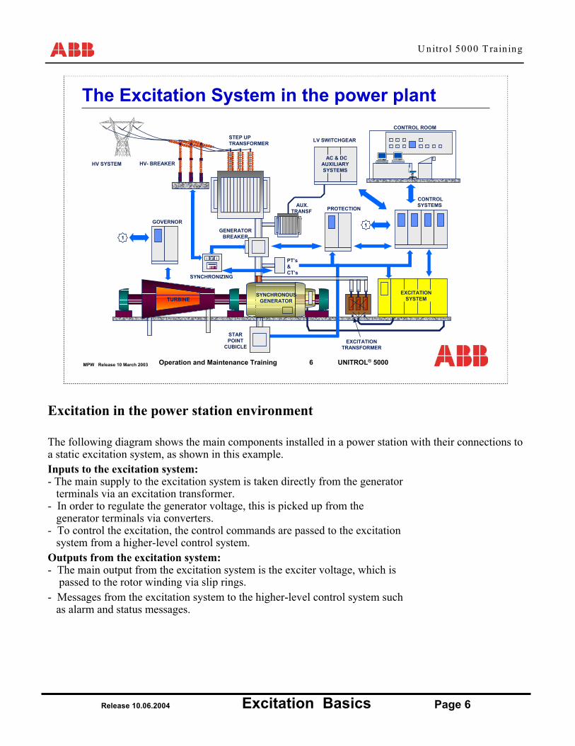
Excitation in the power station environment
The following diagram shows the main components installed in a power station with their connections to a static excitation system, as shown in this example. Inputs to the excitation system:- The main supply to the excitation system is taken directly from the generator
terminals via an excitation transformer.- In order to regulate the generator voltage, this is picked up from the
generator terminals via converters.- To control the excitation, the control commands are passed to the excitation
system from a higher-level control system.Outputs from the excitation system:- The main output from the excitation system is the exciter voltage, which is
passed to the rotor winding via slip rings.- Messages from the excitation system to the higher-level control system such
as alarm and status messages.

U nitro l 5000 T rain ing
Release 10.06.2004 Excitation Basics Page 7
MPW Release 10 March 2003 7Operation and Maintenance Training UNITROL® 5000
The Synchronous Machine on the Network
If Ug
Controlled Object Disturbance
SynchronousMachine
Network
ExcitationSystem
A generator is normally a small contributor to a large network. The characteristic is generally determined by the machine and network. The
excitation system only allows a correction of the overall behaviour.
A regulated synchronous machine coupled to the network can be represented in simplified form.The synchronous machine represents the regulated object. All other components together form the regulator or excitation system. In parallel operation with the network, the network influences the behaviour of the closed regulating circuit and in this sense acts as an external interference variable.
The characteristics of the synchronous machine and the network are largely determined by the equipment that has been used.i.e. The generator, the transformers, the transmission cables, etc.
The excitation system can be used to set up the steady state operating conditions of the machine.In transient conditions, the excitation only allows an adjustment of the overall behaviour in the sense of a technical optimisation. Optimisation is done during commissioning.
U nitro l 5000 T rain ing
Release 10.06.2004 Excitation Basics Page 8
MPW Release 10 March 2003 8Operation and Maintenance Training UNITROL® 5000
Steady State & Transient Behaviour
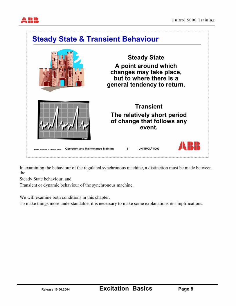
Steady StateA point around which
changes may take place, but to where there is a
general tendency to return.
TransientThe relatively short period of change that follows any
event.
In examining the behaviour of the regulated synchronous machine, a distinction must be made between theSteady State behaviour, and Transient or dynamic behaviour of the synchronous machine.
We will examine both conditions in this chapter.To make things more understandable, it is necessary to make some explanations & simplifications.

U nitro l 5000 T rain ing
Release 10.06.2004 Excitation Basics Page 9
MPW Release 10 March 2003 9Operation and Maintenance Training UNITROL® 5000
Generator Electrical & Mechanical Behaviour
Mechanical Behaviour
Machine Speed
Real Power
Electrical Behaviour
Machine Voltage
Reactive Power
The generator is where the conversion between mechanical energy and electrical energy takes place.
The generator has displays both electrical and mechanical behaviour. As this is the place where the conversion takes place it makes things simpler if a separation is made between mechanical and electrical behaviour.
Electrical BehaviourExcitation CurrentMachine VoltageReactive Power
Mechanical BehaviourMachine SpeedMachine Torque (= Power in the per unit system)
In many ways there is a strong analogy between the mechanical behaviour and the electrical behaviour of the machine, however they are most definitely separate.
It would be very nice if it were possible to make real power using the excitation system!!!!(You could then make real power without the need for coal, oil, gas etc.)

U nitro l 5000 T rain ing
Release 10.06.2004 Excitation Basics Page 10
MPW Release 10 March 2003 10Operation and Maintenance Training UNITROL® 5000
The Generalized Equivalent CircuitNorth
South
Significant Air Gap
(Quadrature Axis)
Salient Pole Machine
Solid Pole Machine
Generalized Equivalent CircuitThe formation of an equivalent machine diagram helps us to understand the synchronous machine.In this course we will concentrate on a cylindrical or solid pole machine.
To form a generalized equivalent circuit for a synchronous machine of any construction it is necessary to consider that the machine has two axis. A direct axis, and a quadrature axis.The direct axis arises from flux that flows directly from the pole face to the stator winding.The quadrature axis arises from flux that flows perpendicular to the pole face.
The solid pole machine has a smooth cylindrical profile. The flux can therefore flow between the rotor and the stator in any direction with similar difficulty, because the main obstacle is the air gap.
For a salient pole machine, the air gap in the direct axis is quite small, however the air gap in thequadrature axis is significant, and therefore it becomes necessary to produce a different (and more complex) equivalent circuit.

U nitro l 5000 T rain ing
Release 10.06.2004 Excitation Basics Page 11
MPW Release 10 March 2003 11Operation and Maintenance Training UNITROL® 5000
The solid pole synchronous machine
• High speed application for speed range > 1500 rpm • Xd and Xq are similar
The magnetic flux between rotor and stator has a small air gap in both the quadratureand direct axis.
The cylindrical / solid pole machine is characterized by:
Xd = Xq = Synchronous Reactance

U nitro l 5000 T rain ing
Release 10.06.2004 Excitation Basics Page 12
MPW Release 10 March 2003 12Operation and Maintenance Training UNITROL® 5000
The Salient Pole Machine
• Low speed application for speed range < 1500 rpm• Xd > Xq
The flux in the quadrature axis
must cover a significant air
gap
The salient pole machine is characterized by
Xd = Direct Axis Reactance > Xq Quadrature Axis Reactance
The difference between the solid pole machine and the salient pole machine makes an important difference to the operating characteristic of the machine.
For the moment, we shall study the equivalent circuit of the solid pole machine, but later on we return to the salient pole machine in order to examine the differences.
U nitro l 5000 T rain ing
Release 10.06.2004 Excitation Basics Page 13
MPW Release 10 March 2003 13Operation and Maintenance Training UNITROL® 5000
The Substitution Diagram of the Synchronous Machine
Q-Axis
D-Axis
Xd
Ep
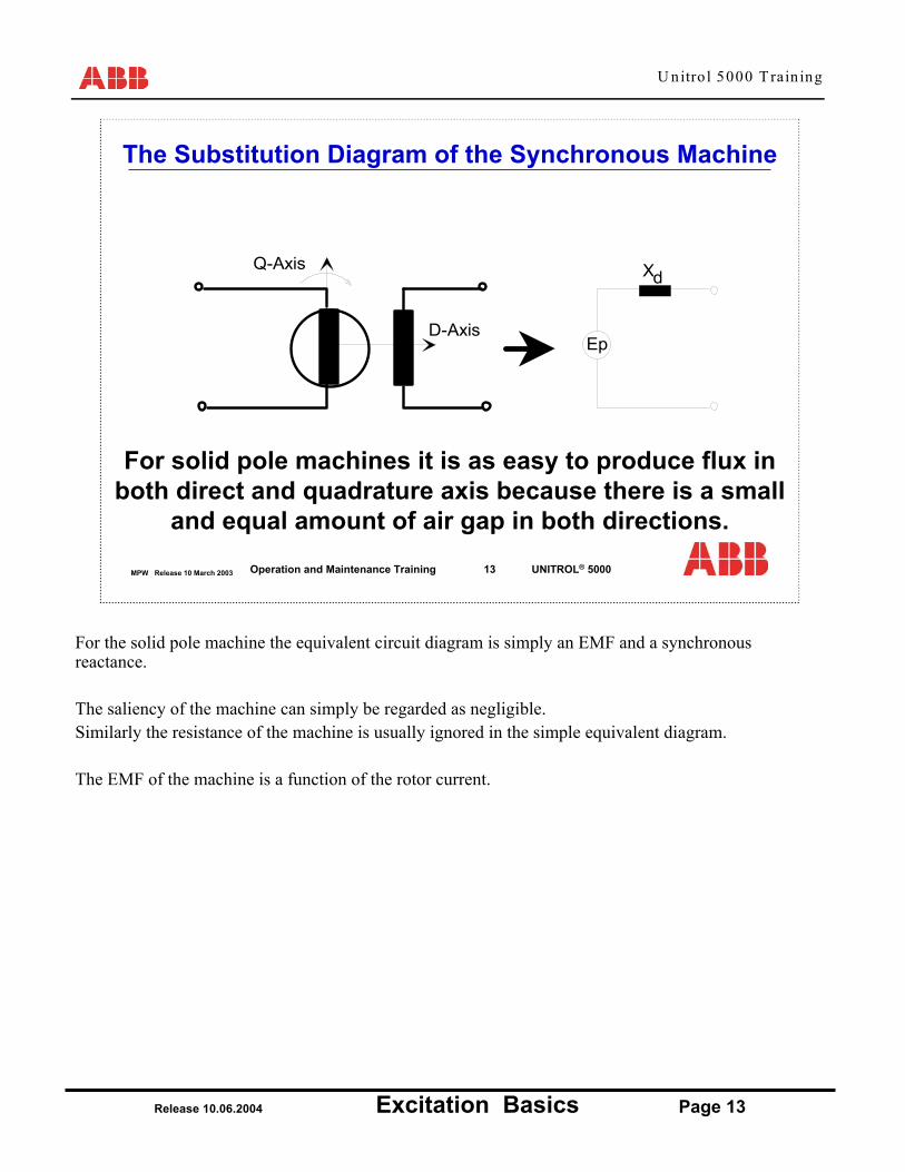
For solid pole machines it is as easy to produce flux in both direct and quadrature axis because there is a small
and equal amount of air gap in both directions.
For the solid pole machine the equivalent circuit diagram is simply an EMF and a synchronous reactance.
The saliency of the machine can simply be regarded as negligible.Similarly the resistance of the machine is usually ignored in the simple equivalent diagram.
The EMF of the machine is a function of the rotor current.

U nitro l 5000 T rain ing
Release 10.06.2004 Excitation Basics Page 14
MPW Release 10 March 2003 14Operation and Maintenance Training UNITROL® 5000
Generator Name Plate ValuesWhat values can you find on the name plate of your synchronous machine?
Physical values of your machine AbsoluteValue
Per unitvalue
Unit
Apparent PowerMachine Voltage
Power FactorRated Field Current
FrequencySpeed
MVAV-A
Hzrpm
1111
11
No Load Field Current A
What kind of generator is in your power station?
Is it a salient pole machine or a sold pole machine?
What is the per unit system?

U nitro l 5000 T rain ing
Release 10.06.2004 Excitation Basics Page 15
MPW Release 10 March 2003 15Operation and Maintenance Training UNITROL® 5000
Generator Operating Modes
1. No Load Operation.
2. Machine loaded and operating in parallel with other machines on a large network.
3. Machine loaded and operating alone with load
= island operation.
Now that an equivalent Steady State Equivalent diagram has been made, we can consider the circuit in a few different operating modes.
We can identify 3 different generator operating modes.
1. No Load Operation.The machine runs at nominal speed and the generator circuit breaker is open.The speed of the machine is set by the turbine.
2. Machine loaded and operating on a large network.The machine is only a small generator compared to the entire network. It can therefore not really influence either the network voltage or the network frequency.
3. Island OperationThe machine is connected to a load without any other generator being connected.The frequency and voltage depends on the Generator AND the Load.(In actual fact both of these quantities must be actively controlled to achieve acceptable operation.)
In he following slides, we shall consider only the first two scenarios.

U nitro l 5000 T rain ing
Release 10.06.2004 Excitation Basics Page 16
MPW Release 10 March 2003 16Operation and Maintenance Training UNITROL® 5000
Generator No Load Characteristic
Ug
IfIfo
Ugn
Saturation
No load field current
Generatorrated voltage
Xd
EpUG
EMF is dependant on excitation current & speed
No Load Operation
As the stator current is zero;The terminal voltage of the machine = The EMF of the machine
Ug = Ep
The voltage is a function of Speed and Excitation Current.
At lower values of field current, the relationship between field current and terminal voltage is linear. However, above a certain level of current, the machine starts to saturate.
Most machines are designed to have the nominal voltage of the machine lying just inside the saturated region of the characteristic.
In the range up to nominal generator voltage, a more or less linear relationship exists between field current and generator voltage. When the generator voltage exceeds the nominal value, a saturation effect takes place which is essentially determined by the design of the stator iron. If one wishes to increase the generator voltage further, above its nominal value, the field current must be increased over-proportionately.

U nitro l 5000 T rain ing
Release 10.06.2004 Excitation Basics Page 17
MPW Release 10 March 2003 17Operation and Maintenance Training UNITROL® 5000
Xd
EpUG N
etw
ork
IG X tr + ex
Ubus
Generator On Load
The machine is now connected to the Network.
The turbine delivers some load, causing a current to flow.
The excitation system can change the EMF of the machine, but theeffect on the network is considered to be negligible.
Generator On Load
The machine is now connected to a large network through a step up transformer, and the turbine delivers a real load (MW).
The internal Emf of the machine is still determined by the excitation current, however the terminal voltage of the machine also strongly dependant upon the network.
If the machine is under load, a current flows in the stator windings, which causes a voltage drop through the synchronous reactance. If the excitation current remains constant, the terminal voltage would therefore be reduced. Here, the excitation system has the function of preventing this drop in voltage by altering the excitation current.
U nitro l 5000 T rain ing
Release 10.06.2004 Excitation Basics Page 18
MPW Release 10 March 2003 18Operation and Maintenance Training UNITROL® 5000
δ 1
UgEMF 1
EMF 2
δ 2
Ig 1 * XdIg 2 * Xd
Constant power factor.
Generator On Load
δ 1
Ug
EMF 1 = EMF 2
δ 2
Ig 1 * Xd
Ig 2 * Xd
EMF 1Ig1
Ig2
Constant Field Current.
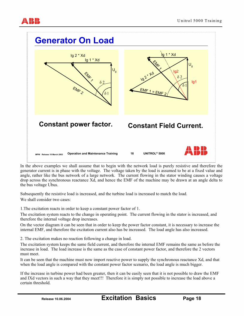
In the above examples we shall assume that to begin with the network load is purely resistive and therefore the generator current is in phase with the voltage. The voltage taken by the load is assumed to be at a fixed value and angle, rather like the bus network of a large network. The current flowing in the stator winding causes a voltage drop across the synchronous reactance Xd, and hence the EMF of the machine may be drawn at an angle delta to the bus voltage Ubus.
Subsequently the resistive load is increased, and the turbine load is increased to match the load.We shall consider two cases:
1.The excitation reacts in order to keep a constant power factor of 1.The excitation system reacts to the change in operating point. The current flowing in the stator is increased, and therefore the internal voltage drop increases.On the vector diagram it can be seen that in order to keep the power factor constant, it is necessary to increase the internal EMF, and therefore the excitation current also has be increased. The load angle has also increased.
2. The excitation makes no reaction following a change in load.The excitation system keeps the same field current, and therefore the internal EMF remains the same as before the increase in load. The load increase is the same as the case of constant power factor, and therefore the 2 vectors must meet.It can be seen that the machine must now import reactive power to supply the synchronous reactance Xd, and that when the load angle is compared with the constant power factor scenario, the load angle is much bigger.
If the increase in turbine power had been greater, then it can be easily seen that it is not possible to draw the EMF and IXd vectors in such a way that they meet!!! Therefore it is simply not possible to increase the load above a certain threshold.

U nitro l 5000 T rain ing
Release 10.06.2004 Excitation Basics Page 19
MPW Release 10 March 2003 19Operation and Maintenance Training UNITROL® 5000
δ=45
ωel
ωmech
ωel
ωmech
δ=90
ωel
ωmech
δ=0
ω
"rubber band"
T95_0154.DRW
o o o
The Synchronizing Torque
The importance of the angle delta can be seen from the previous example.The drawing of the voltage drop and the EMF is no longer possible when delta reaches 90°. At this point it would not be possible to remain synchronized with the network.We could see that if the excitation current is increased, then the situation is changed. The excitation current therefore provides a synchronizing torque.
One analogy that is used, is to think of an elastic band.
We can imagine the rotor of the machine to be connected to the network voltage by an elastic band.•The strength of the elastic band is dependant on its elastic constant. In the case of the machine, the elastic constant is variable, and is dependant on the amount of excitation current.•The extension of the elastic band depends on how strongly it is pulled. In the case of the machine this is the amount of torque applied to the shaft.
If the torque is increased, then the elastic band stretches.
If the excitation current is increased, then the elastic band becomes stronger, and the rotor is pulled back towards the network voltage.
U nitro l 5000 T rain ing
Release 10.06.2004 Excitation Basics Page 20
MPW Release 10 March 2003 20Operation and Maintenance Training UNITROL® 5000
Stability limitMd
δ
Μ d2
Md1
~
~
I
I
f2
f1Drive torque
δ δ 12
δδ sinsin ⋅⋅
=⋅⋅=d
GpGpd X
UEIEM
The Torque Equation
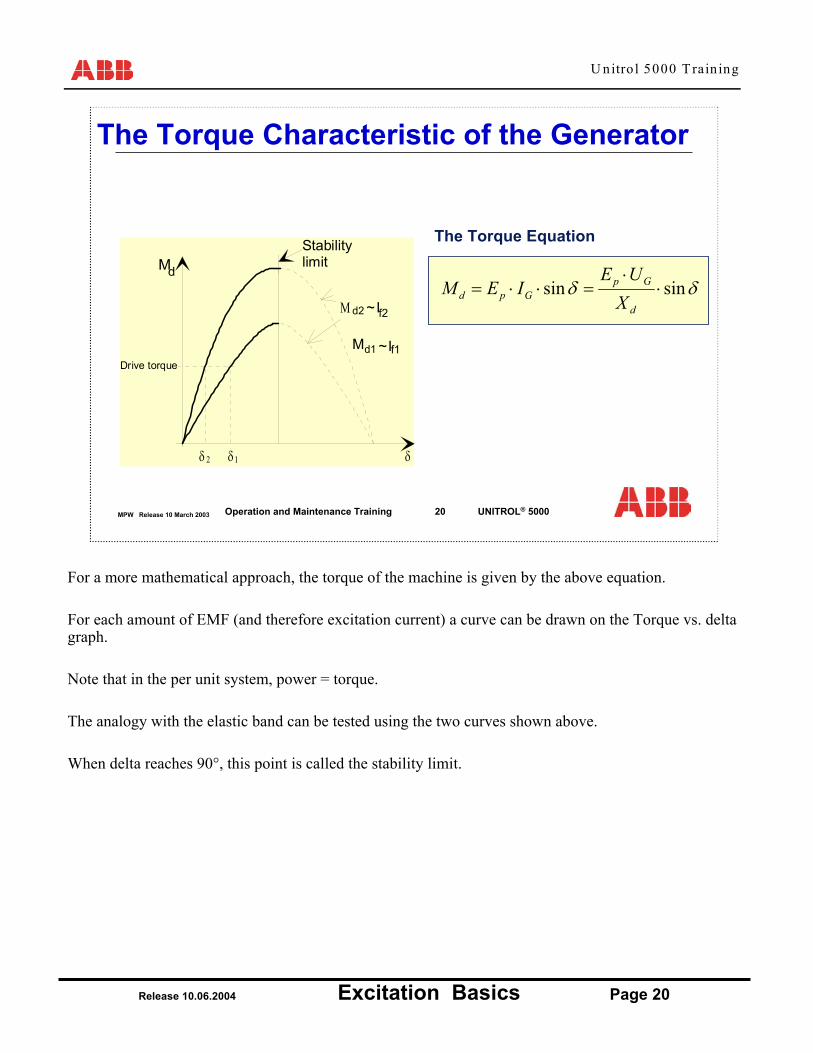
The Torque Characteristic of the Generator
For a more mathematical approach, the torque of the machine is given by the above equation.
For each amount of EMF (and therefore excitation current) a curve can be drawn on the Torque vs. delta graph.
Note that in the per unit system, power = torque.
The analogy with the elastic band can be tested using the two curves shown above.
When delta reaches 90°, this point is called the stability limit.
U nitro l 5000 T rain ing
Release 10.06.2004 Excitation Basics Page 21
MPW Release 10 March 2003 21Operation and Maintenance Training UNITROL® 5000
ActivePower
Reactivepower
ratedpower
Motor
Drive Limit
P
+ Q- Q
Sn
1xd
Field currentlimit
Load anglelimit
-1 +1
1
Pf
Ifoover
excitedunder
excited
δ
Drive Limit
The Power Chart of the Synchronous Machine
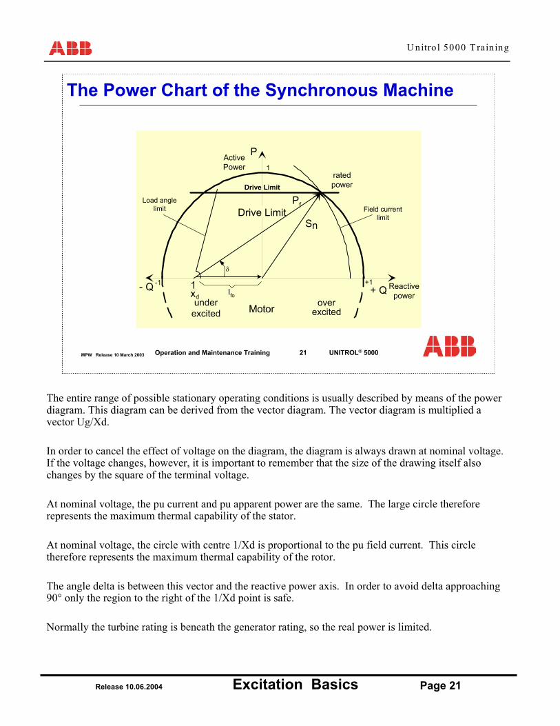
The entire range of possible stationary operating conditions is usually described by means of the power diagram. This diagram can be derived from the vector diagram. The vector diagram is multiplied a vector Ug/Xd.
In order to cancel the effect of voltage on the diagram, the diagram is always drawn at nominal voltage. If the voltage changes, however, it is important to remember that the size of the drawing itself also changes by the square of the terminal voltage.
At nominal voltage, the pu current and pu apparent power are the same. The large circle therefore represents the maximum thermal capability of the stator.
At nominal voltage, the circle with centre 1/Xd is proportional to the pu field current. This circle therefore represents the maximum thermal capability of the rotor.
The angle delta is between this vector and the reactive power axis. In order to avoid delta approaching 90° only the region to the right of the 1/Xd point is safe.
Normally the turbine rating is beneath the generator rating, so the real power is limited.

U nitro l 5000 T rain ing
Release 10.06.2004 Excitation Basics Page 22
MPW Release 10 March 2003 22Operation and Maintenance Training UNITROL® 5000
Power Chart inc. Salient Pole
active power P
reactive power Q
maximum turbine power
ϕ
I fn
I GN
δ
0-1 1Xq1- 1
Xd-
capacitive generator current limiter inductive generator current limiter
reactive power limiter(P/Q-limiter)
minimumfield current limiter
maximum field current limiter
XiUact
2 -1
region of underexcitation region of overexcitation
The power chart for a salient pole machine is quite different to the solid pole machine.
The origin of the Field vector is different. 1/XqThe vector measurement starts from the circle formed between the 1/Xq and 1/Xd points.

U nitro l 5000 T rain ing
Release 10.06.2004 Excitation Basics Page 23
MPW Release 10 March 2003 23Operation and Maintenance Training UNITROL® 5000
(“Static” or Steady State)1. The voltage at the consumer connection
should be kept within defined limits
2. Stable reactive power distribution
3. Setting of Reactive Power should ensure efficient power transmission
4. Generator should be kept within safe operational limits
Static Network Requirements of the AVR
The basic requirements of the automatic voltage regulating systems, which must be fulfilled in a typical network under stationary conditions, i.e. without faults, are:
1. The voltage at the consumer connection should be kept within acceptable limits.
The consumer operates equipment that is designed to work within a particular voltage tolerance.
2. Stable reactive power distribution in the case of several parallel-operated generators within the power station must be guaranteed.
Generators can absorb or generate reactive power. In order to have stable operation, it is essential that reactive power is shared and not merely passed around between generators!
3. The reactive power distribution within the network system should create minimal line losses, with good stability, also during load changes.
If a network is to be operated efficiently it is essential to have some way of managing the node voltages at various points in the network. This can be achieved by excitation systems and tap changing transformers.
4. The generator should always be operated within the safe operating limits.(see power chart)
U nitro l 5000 T rain ing
Release 10.06.2004 Excitation Basics Page 24
MPW Release 10 March 2003 24Operation and Maintenance Training UNITROL® 5000
12
3
T95_0157.DRW
Tie
Regional grid
Substation
Power station
The Network
A machine may be connected to a large and
complex network.
How can the reactive power be used to understand the
relationship between the machine and the
network?
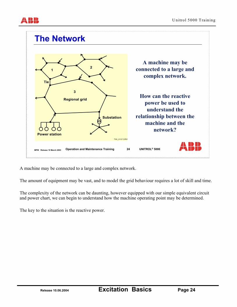
A machine may be connected to a large and complex network.
The amount of equipment may be vast, and to model the grid behaviour requires a lot of skill and time.
The complexity of the network can be daunting, however equipped with our simple equivalent circuit and power chart, we can begin to understand how the machine operating point may be determined.
The key to the situation is the reactive power.

U nitro l 5000 T rain ing
Release 10.06.2004 Excitation Basics Page 25
MPW Release 10 March 2003 25Operation and Maintenance Training UNITROL® 5000
RL UNet
GXTr Xe
Substitution Diagram of the Network with the Generator
The machine and the network can be represented by the greatly simplified equivalent circuit shown above.
The equivalent-circuit diagram shows the generator G, which can also stand for an entire power station, with the reactance XTr (transformer reactance) between generator terminals and high voltage busbar. The resulting load impedance ZL relates to this feed point. The rest of the system is reduced to an external reactance Xe and a voltage of the rigid networks. All power-generating units are united at this point. The line resistance's in the immediate vicinity can usually be ignored, whereas the capacity of longer transmission lines must be taken into account.

U nitro l 5000 T rain ing
Release 10.06.2004 Excitation Basics Page 26
MPW Release 10 March 2003 26Operation and Maintenance Training UNITROL® 5000
RL UNet
GXTr Xe
UG = 1.05 pu
= 0.1 pu = 0.2 pu
Consumers
UN = 1.0 pu
IQReactive Power
Export of Reactive Power
If the per unit terminal voltage is greater than per unit network voltage, reactive power is exported.
If reactive power is exported, then the per unit generator voltage will be greater than the per unit network voltage.
The generator is therefore making a positive contribution to the network voltage. i.e. keeping the voltage level up.
Note: The measurement point is important!
If the reactive power is measured at the generator terminals, then it is the machine contribution alone which is considered. The transformer and external reactance will also requires reactive power, and therefore the net effect may not be a positive contribution.
If the reactive power is measured after the step up transformer, then it is the combination of the machine + transformer that is considered.
From the network point of view, it is the measurement after the transformer that should be considered.

U nitro l 5000 T rain ing
Release 10.06.2004 Excitation Basics Page 27
MPW Release 10 March 2003 27Operation and Maintenance Training UNITROL® 5000
RL UNet
GXTr Xe
UG = 0.95 pu
= 0.1 pu = 0.2 pu
Consumers
UN = 1.0 pu
IQReactive Power
Import of Reactive Power
If the per unit terminal voltage is lower than per unit network voltage, reactive power is imported.
If reactive power is imported, then the per unit generator voltage will be less than the per unit network voltage.
The generator is therefore making a negative contribution to the network voltage. i.e. keeping the voltage level down.
Note: The measurement point is important!
If the reactive power is measured at the generator terminals, then it is the machine contribution alone which is considered. The transformer and external reactance will also requires reactive power, and therefore the net effect may not be a negative contribution.
If the reactive power is measured after the step up transformer, then it is the combination of the machine + transformer that is considered.
From the network point of view, it is the measurement after the transformer that should be considered.
U nitro l 5000 T rain ing
Release 10.06.2004 Excitation Basics Page 28
MPW Release 10 March 2003 28Operation and Maintenance Training UNITROL® 5000
Analogy between governor and AVR
G
RT
Turbine
G R
Generator
P
n,f
Q
U
T 95_0158.DR W
Network Network
AVR
Governor
• Static behavior of closed loop control• Analogy between governor and AVR
Steady State REAL Power Depends on
the mechanical output of the power plant
e.g. Amount of gas that is
burnt
Steady State REACTIVE
Power Depends on
the excitation system.
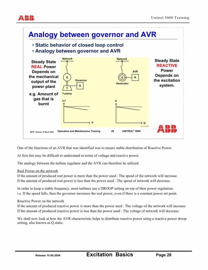
One of the functions of an AVR that was identified was to ensure stable distribution of Reactive Power.
At first this may be difficult to understand in terms of voltage and reactive power.
The analogy between the turbine regulator and the AVR can therefore be utilized.
Real Power on the networkIf the amount of produced real power is more than the power used : The speed of the network will increase.If the amount of produced real power is less than the power used : The speed of network will decrease.
In order to keep a stable frequency, most turbines use a DROOP setting on top of their power regulation.i.e. If the speed falls, then the governor increases the real power, even if there is a constant power set point.
Reactive Power on the networkIf the amount of produced reactive power is more than the power used : The voltage of the network will increase.If the amount of produced reactive power is less than the power used : The voltage of network will decrease.
We shall now look at how the AVR characteristic helps to distribute reactive power using a reactive power droop setting, also known as Q static.

U nitro l 5000 T rain ing
Release 10.06.2004 Excitation Basics Page 29
MPW Release 10 March 2003 29Operation and Maintenance Training UNITROL® 5000
UG
pos. static
neg. static
+Q-Q
In the AVR, it is possible to give the machine a different characteristic by adjusting the droop.
Static behaviour of AVR
Reactive power influence to AVR
In Unitrol 5000 it is possible to use either a positive droop or a negative droop. This is set by a parameter.

U nitro l 5000 T rain ing
Release 10.06.2004 Excitation Basics Page 30
MPW Release 10 March 2003 30Operation and Maintenance Training UNITROL® 5000
G AVR +Exciter
G AVR +Exciter
BUS NETWORK
Setpoint 1 Setpoint 2
Vbus Vbus• If the setpoint of
Generator 1 was higher than Generator 2 then the two machines could never share reactive power.
• Generator 1 would export reactive power and Generator 2 would import reactive power.
• No stable point would be possible.
Generators Operating On The Same Bus.Without Generator Transformer
Two generators operating on the same bus are considered in this example.
The terminal voltage MUST be the same on both machines because they are directly connected.
If the setpoint on machine 1 was larger than on machine 2, then the AVR of machine 1 would keep increasing its excitation current until eventually the over excitation limit would become active.
In the same way, the AVR of machine 2 would keep decreasing the excitation current until eventually its under excitation limit would become active.
Reactive power would therefore be passed from machine 1 to machine 2, regardless of network requirements!

U nitro l 5000 T rain ing
Release 10.06.2004 Excitation Basics Page 31
MPW Release 10 March 2003 31Operation and Maintenance Training UNITROL® 5000
Voltage generator 2
Voltage generator 1
Voltage
-ve Q +ve Q
• Each controller TRIES to make its own voltage.
• BUT both generators are connected together.
• As the characteristics do not cross, operation is not stable.
Generators in Parallel without Droop
The control characteristic of the 2 generators is plotted on the above graph.
There is no point at which the 2 characteristics cross, and therefore the distribution of reactive power between the machines is undefined.

U nitro l 5000 T rain ing
Release 10.06.2004 Excitation Basics Page 32
MPW Release 10 March 2003 32Operation and Maintenance Training UNITROL® 5000
Reactive Power Distribution
AVR
Generator 1
AVR
Generator 2
BusbarGrid
Uref1 Uref2
IQ
Q, IQ
U
Busbar voltageUref1
Uref2
IQ IQ
Generator 2 Generator 1
For the 2 machines considered we could see that:
for machine 1, the reactive power was positive, andfor machine 1, the reactive power was negative.
HOWEVER, this was the same reactive power!
Therefore, it can be said that the reactive power of one machine AS SEEN FROM THE OTHER machine is opposite.
A droop characteristic is now applied to each of the 2 AVR’s with the same droop characteristic.
The droop characteristic of machine 2 as seen by machine 1 is in the opposite direction as its own.
U nitro l 5000 T rain ing
Release 10.06.2004 Excitation Basics Page 33
MPW Release 10 March 2003 33Operation and Maintenance Training UNITROL® 5000
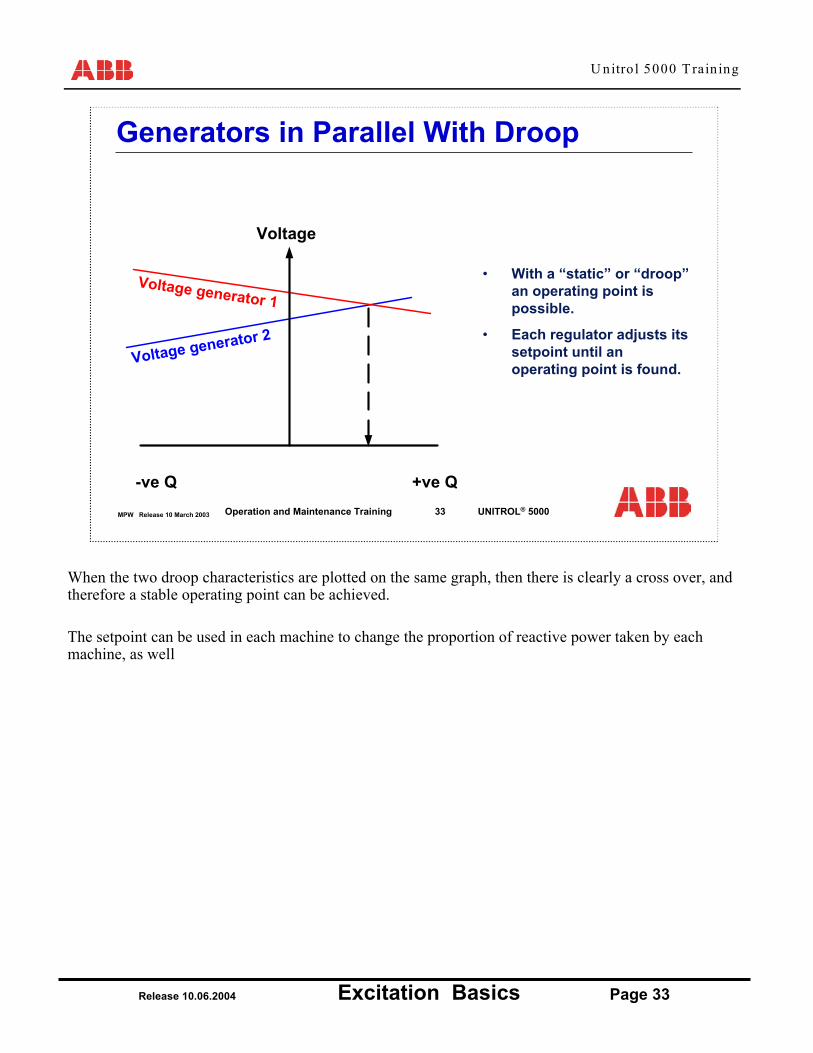
• With a “static” or “droop” an operating point is possible.
• Each regulator adjusts its setpoint until an operating point is found.
Voltage generator 2
Voltage generator 1
Voltage
-ve Q +ve Q
Generators in Parallel With Droop
When the two droop characteristics are plotted on the same graph, then there is clearly a cross over, and therefore a stable operating point can be achieved.
The setpoint can be used in each machine to change the proportion of reactive power taken by each machine, as well
U nitro l 5000 T rain ing
Release 10.06.2004 Excitation Basics Page 34
MPW Release 10 March 2003 34Operation and Maintenance Training UNITROL® 5000
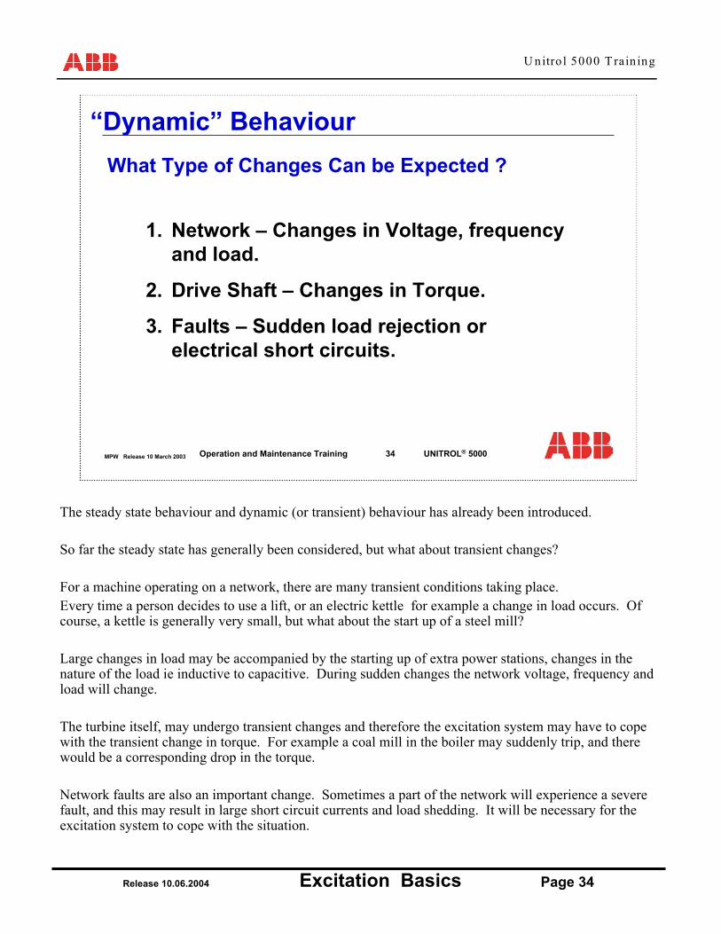
1. Network – Changes in Voltage, frequency and load.
2. Drive Shaft – Changes in Torque.
3. Faults – Sudden load rejection or electrical short circuits.
“Dynamic” BehaviourWhat Type of Changes Can be Expected ?
The steady state behaviour and dynamic (or transient) behaviour has already been introduced.
So far the steady state has generally been considered, but what about transient changes?
For a machine operating on a network, there are many transient conditions taking place.Every time a person decides to use a lift, or an electric kettle for example a change in load occurs. Of course, a kettle is generally very small, but what about the start up of a steel mill?
Large changes in load may be accompanied by the starting up of extra power stations, changes in the nature of the load ie inductive to capacitive. During sudden changes the network voltage, frequency and load will change.
The turbine itself, may undergo transient changes and therefore the excitation system may have to cope with the transient change in torque. For example a coal mill in the boiler may suddenly trip, and there would be a corresponding drop in the torque.
Network faults are also an important change. Sometimes a part of the network will experience a severe fault, and this may result in large short circuit currents and load shedding. It will be necessary for the excitation system to cope with the situation.

U nitro l 5000 T rain ing
Release 10.06.2004 Excitation Basics Page 35
MPW Release 10 March 2003 35Operation and Maintenance Training UNITROL® 5000
Flux, Voltage and Frequency
UG
f
115%110%
100%
U
fV/Hz-gradient = dV/df
Maximum Voltage = f{insulation} Max Voltage at Nominal Speed
Recall once again, the no load characteristic of the machine.The voltage of the machine in no load is dependant on:1. Speed, and2. Field Current.The same is still true in load operation, however there is the additional influence of the network/load.
If the voltage of the machine is regulated by a voltage regulator, then the speed can present a problem. i.e. at lower speeds, more excitation current is required to achieve the same voltage. As we have already seen, the machine displays saturation above a certain amount of current. The saturation curve becomes flatter at even higher currents.
To avoid the possibility of saturation, Unitrol 5000 uses a software function called a “Volt per Herz” Limiter.
The limitation of machine voltage should be defined according to a speed dependant characteristic. The characteristic has a cut off point that reflects the insulation limit of the machine. Naturally the insulation properties of the machine are not speed dependant.
Should the voltage reach the level of limitation, then Unitrol 5000 will automatically take action to ensure that the voltage does not increase any further.
U nitro l 5000 T rain ing
Release 10.06.2004 Excitation Basics Page 36
MPW Release 10 March 2003 36Operation and Maintenance Training UNITROL® 5000
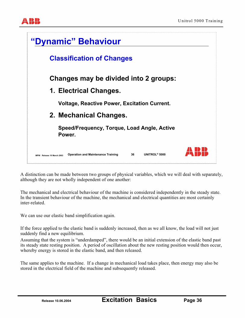
Changes may be divided into 2 groups:
1. Electrical Changes.
Voltage, Reactive Power, Excitation Current.
2. Mechanical Changes.
Speed/Frequency, Torque, Load Angle, Active Power.
“Dynamic” Behaviour
Classification of Changes
A distinction can be made between two groups of physical variables, which we will deal with separately, although they are not wholly independent of one another:
The mechanical and electrical behaviour of the machine is considered independently in the steady state. In the transient behaviour of the machine, the mechanical and electrical quantities are most certainly inter-related.
We can use our elastic band simplification again.
If the force applied to the elastic band is suddenly increased, then as we all know, the load will not just suddenly find a new equilibrium.Assuming that the system is “underdamped”, there would be an initial extension of the elastic band past its steady state resting position. A period of oscillation about the new resting position would then occur, whereby energy is stored in the elastic band, and then released.
The same applies to the machine. If a change in mechanical load takes place, then energy may also be stored in the electrical field of the machine and subsequently released.

U nitro l 5000 T rain ing
Release 10.06.2004 Excitation Basics Page 37
MPW Release 10 March 2003 37Operation and Maintenance Training UNITROL® 5000
S
UgX E
If = konst.
t
Ug
Ugo
t = 0
∆U = Ig *Xd
Behaviour of Generator voltage in case of reactive power surgewith constant field current
What happens when a reactive load is suddenly applied to an idling generator?
Reactive Power Surge
Example of an Electrical Change:The transient effect varies greatly, depending on whether a change in active power or reactive power is involved. We will consider the case of a pure reactive power change, for example when an idling machine is connected to an inductive load.
The unloaded generator has a terminal voltage Ug which is equal to the induced rotor voltage Ep.After the circuit breaker S is closed, a reactive current Ig begins to flow immediately and causes a voltage drop through the generator reactance.The original magnetic flux, which passes through stator and rotor, cannot change instantly. The consequence of this is that a contrary current is induced in the rotor circuit via the air gap in order to compensate the changes on the stator side and maintain the balance of the circulation.
In the simplified equivalent circuit diagram shown, this means that the direct axis reactance Xd is replaced by the either the transient reactance Xd’, or the sub-transient reactance Xd’’ (see below) which is 5…10 times smaller than the synchronous reactance Xd.
Note: Most generators have a rotor damper winding. The damper winding is an extra cage type winding that is not connected to the main winding, and allows an induced current to flow that is related to the slip frequency between the rotor and stator fields. The induced current helps to keep the rotor synchronized with the stator, by developing a synchronizing torque. The damper winding may be compared with the rotor winding of an induction motor.This winding is responsible for introducing the sub-transient reactance Xd’’For very fast transient changes, it is this sub-transient reactance which is used.

U nitro l 5000 T rain ing
Release 10.06.2004 Excitation Basics Page 38
MPW Release 10 March 2003 38Operation and Maintenance Training UNITROL® 5000
with rotating exciter
t
Ug
Ugo
t = 0
∆U = Ig *Xd
static excitation systemsWhen an AVR is used, the excitation current is adjusted to bring the voltage back to its original value
Generator voltage in case of reactive power surge
Reactive Power Surge
For a machine operating with Automatic Voltage Regulation, the transient condition is automatically compensated.
The initial drop is fixed by the sub/transient reactance of the machine and the generator current.
The regulator reacts to the drop in voltage by automatically increasing the field current, and therefore returning the voltage to its previous voltage level.
The response of a static excitation system and a rotating exciter machine can be compared in the example above.

U nitro l 5000 T rain ing
Release 10.06.2004 Excitation Basics Page 39
MPW Release 10 March 2003 39Operation and Maintenance Training UNITROL® 5000
δ
UE
I · XDP = ω· M
P = U · I = U ·
Torque Equation
M - M = Θ
A
E
A
X D
E · sin δ
A Edωdt
θ Inertiaω speed
ω
PA URo R1
Active power surgewith power oscillations
Behaviour of generator voltage during power surges
Change in Real Power (ohmic Load)
The behaviour of the machine when it reacts to a change in mechanical load is quite different.
When the switch is closed, the load current through R1 flows instantaneously.The turbine response, however is much slower, and the energy being supplied to the load must come either from stored kinetic energy in the shaft, or from the energy stored in the field of the generator. (analogous to the stored “elastic band” energy).
If the field energy was kept constant, then all of the energy must be supplied by releasing the kinetic of the shaft, which therefore causes the shaft to slow down.
Eventually the turbine governor will react to the fall in speed, and the turbine power will be increased.
In Unitrol 5000, there is a feature called the “Power System Stabilizer”. This purposefully uses the excitation system to smooth out the exchange of energy between the shaft and the system using the energy stored in the field of the generator.

U nitro l 5000 T rain ing
Release 10.06.2004 Excitation Basics Page 40
MPW Release 10 March 2003 40Operation and Maintenance Training UNITROL® 5000
Overvoltage relay
IQ x Xd "
t = 0 1 Sec.
t
Ug
Uo
with AVR (static excitation system)with constant field current
Generator Voltage during Reactive Load Rejection
Load Rejection
Look at the generator ratings for:No Load Field Current, andFull Load Field Current
If there were to be a load rejection (the generator circuit breaker opens) at the nominal operating point of the generator then you can easily see that the field current would be much too high!
An important function of the AVR is therefore to bring the voltage back to a safe level in the event of such a load rejection.
The initial rise is dependant on the Xd’’ of the machine, but again the AVR can take fast corrective action to ensure that the over voltage trip level is not reached.

U nitro l 5000 T rain ing
Release 10.06.2004 Excitation Basics Page 41
MPW Release 10 March 2003 41Operation and Maintenance Training UNITROL® 5000
Generator Voltage during Reactive Load Rejection
Example of a load rejection using a Static Excitation System.

U nitro l 5000 T rain ing
Release 10.06.2004 Excitation Basics Page 42
MPW Release 10 March 2003 42Operation and Maintenance Training UNITROL® 5000
Voltage Support during Network Faults
The protection system normally requires that current flows into the fault in order to correctly detect WHICH line should be
disconnected.
It is therefore essential that the excitation system supports the system voltage during the period that the “selection” takes place.
Faults
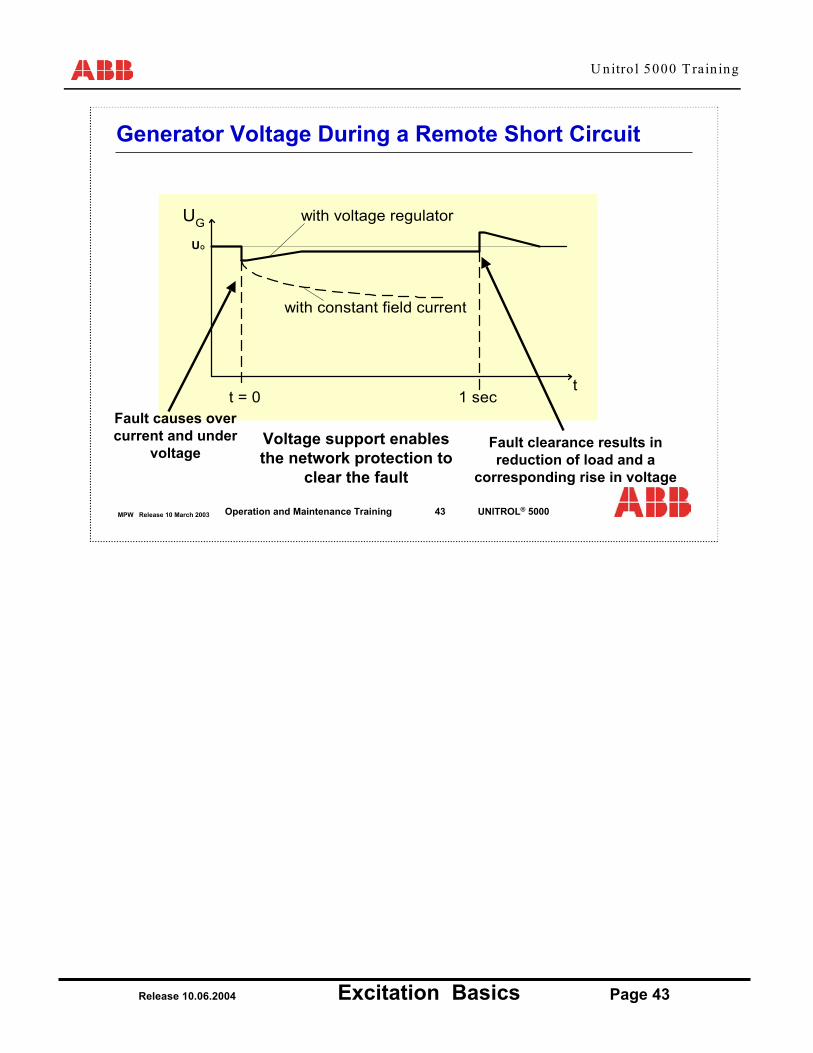
During a distant network fault, it is very important that the network voltage is maintained.
If a fault occurred, then the normally the generator voltage would fall and the generator current would increase.
If this were allowed to continue, the protection relay may not correctly detect where the fault has occurred, resulting in the disconnection of more equipment than was actually necessary.
The AVR helps the selection, by feeding current into the fault.
U nitro l 5000 T rain ing
Release 10.06.2004 Excitation Basics Page 43
MPW Release 10 March 2003 43Operation and Maintenance Training UNITROL® 5000
1 sec
UO
with constant field current
with voltage regulatorUG
t = 0t
Fault causes over current and under
voltageVoltage support enables the network protection to
clear the fault
Fault clearance results in reduction of load and a
corresponding rise in voltage
Generator Voltage During a Remote Short Circuit

U nitro l 5000 T rain ing
Release 10.06.2004 Excitation Basics Page 44
MPW Release 10 March 2003 44Operation and Maintenance Training UNITROL® 5000
The need for de-excitation
Thyristors(Or switch)
ResistorV = -L dI/dt
The field winding consists of a large inductance.
If the current is suddenly interrupted either by a breaker or byturning the converter off, then the voltage will become very large.
One method is the “Crowbar”
Another function that an excitation system has to be able to cope with is de-excitation.
The field current flows through an inductance.
If the current is interrupted for any reason, the inductance will produce an extremely large voltage to try and maintain the flow of current.
On method of overcoming this problem is to introduce a “Crowbar” circuit.A “Crowbar” is a large metal tool used for levering items such as man hole covers. In electrical terms it was used because such a bar could be dropped across the busbars, and the bar would be large enough to take the short circuit current.
In Unitrol 5000 the crowbar is in fact a carefully calculated non-linear resistance. A thyristor switch is used to control when the resistors are connected.
The crowbar is meant to act during emergency de-excitation.

U nitro l 5000 T rain ing
Release 10.06.2004 Excitation Basics Page 45
MPW Release 10 March 2003 45Operation and Maintenance Training UNITROL® 5000
Normal De-excitation
Normally de-excitation of the field is made by “Inverting” the
converter.
This is the fastest way of reducing the
field current.
Normally, de-excitation is done by inverting the converter.This uses the converter to convert DC energy to AC energy, and therefore the current in the rotor is very quickly reduced.

U nitro l 5000 T rain ing
Release 10.06.2004 Excitation Basics Page 46
MPW Release 10 March 2003 46Operation and Maintenance Training UNITROL® 5000
Emergency De-excitation
Crowbar De-excitation occurs
in the event of field breaker
opening, excitation tripping
or field overvoltage.
De-excitation by crowbar is done in the event of a trip because it provides a fail safe method.i.e. If the excitation system is not functioning correctly, then the crowbar provides secure de-excitation.
If for example there were thyristor failures, then inversion would no longer be possible.