02 41 00 Demolition - thomasarchitect.com Ashton House MEP Specs... · Structural Welding...
144
ASHTON HOUSE RENOVATIONS 2013 4/17/2013 CITY OF IOWA CITY INNOVATIVE ENGINEERS, INC. DEMOLITION Project #10140 02 41 00 - 1 SECTION 02 41 00 DEMOLITION PART 1 GENERAL 1.01 SECTION INCLUDES A. Removal and disposal of existing equipment, structures, and associated work. PART 2 PRODUCTS – NOT USED PART 3 EXECUTION 3.01 PREPARATION A. Site Inspection: 1. Prior to all work of this section, carefully inspect entire site and work areas, and all objects designated to be removed and to be preserved. 2. Contractor is responsible for determining actual site conditions, extent to which demolition is required, and method of demolition. 3. Demolition work shown on Drawings is intended to represent general intent only. Demolition shall be complete and adequate for intended purpose and all necessary work, in addition to work indicated on plans and specifications, shall be included. 4. 5. Locate all existing utilities and determine all requirements for disconnecting and capping. B. Clarification: 1. Drawings do not purport to show all objects existing on the site or work areas. Review Work shown on Drawings and sections and verify that conditions as indicated are representative of in-place construction. C. Disconnect, remove, and cap designated utility services within demolition areas shown on Drawings. D. Mark location of disconnected utilities. 3.02 PROTECTION A. Exercise extreme caution in removing adjoining construction, walls, structure and framing so as to preserve the structural integrity, finish and appearance of the existing construction or wall shown to remain. B. Protect Work from injury by keeping all piping capped and plugged or otherwise protected. This includes damage by freezing and/or stoppage from building materials, sand, dirt, or concrete. C. Protect all equipment from damage during project; provide all tarpaulins, drop cloths, barricades, or auxiliary equipment. D. Provide temporary shoring, bracing, and staging as may be required to ensure stability of construction and adjoining structures shown to remain. E. Provide, erect, and maintain temporary enclosures, barriers and security devices. F. Contractor shall be repair damage(s) to surfaces not identified to be demolished to match existing at no cost to Owner. 3.03 TIME SEQUENCE COORDINATION A. In general, coordinate removals with replacement Work such as to coordinate with Owner’s occupancy and construction phases, maintain security at building openings, fire exit requirements, etc. B. Coordinate removal of items from exterior walls with installation of permanent or temporary replacement materials such that the buildings are maintained weather tight at the end of each day.
Transcript of 02 41 00 Demolition - thomasarchitect.com Ashton House MEP Specs... · Structural Welding...
ASHTON HOUSE RENOVATIONS 2013 4/17/2013 CITY OF IOWA CITY
INNOVATIVE ENGINEERS, INC. DEMOLITION Project #10140 02 41 00 - 1
SECTION 02 41 00 DEMOLITION
PART 1 GENERAL
1.01 SECTION INCLUDES
A. Removal and disposal of existing equipment, structures, and associated work.
PART 2 PRODUCTS – NOT USED
PART 3 EXECUTION
3.01 PREPARATION
A. Site Inspection: 1. Prior to all work of this section, carefully inspect entire site and work areas, and all objects designated to
be removed and to be preserved. 2. Contractor is responsible for determining actual site conditions, extent to which demolition is required,
and method of demolition. 3. Demolition work shown on Drawings is intended to represent general intent only. Demolition shall be
complete and adequate for intended purpose and all necessary work, in addition to work indicated on plans and specifications, shall be included.
4. 5. Locate all existing utilities and determine all requirements for disconnecting and capping.
B. Clarification: 1. Drawings do not purport to show all objects existing on the site or work areas. Review Work shown on
Drawings and sections and verify that conditions as indicated are representative of in-place construction.
C. Disconnect, remove, and cap designated utility services within demolition areas shown on Drawings.
D. Mark location of disconnected utilities.
3.02 PROTECTION
A. Exercise extreme caution in removing adjoining construction, walls, structure and framing so as to preserve the structural integrity, finish and appearance of the existing construction or wall shown to remain.
B. Protect Work from injury by keeping all piping capped and plugged or otherwise protected. This includes damage by freezing and/or stoppage from building materials, sand, dirt, or concrete.
C. Protect all equipment from damage during project; provide all tarpaulins, drop cloths, barricades, or auxiliary equipment.
D. Provide temporary shoring, bracing, and staging as may be required to ensure stability of construction and adjoining structures shown to remain.
E. Provide, erect, and maintain temporary enclosures, barriers and security devices.
F. Contractor shall be repair damage(s) to surfaces not identified to be demolished to match existing at no cost to Owner.
3.03 TIME SEQUENCE COORDINATION
A. In general, coordinate removals with replacement Work such as to coordinate with Owner’s occupancy and construction phases, maintain security at building openings, fire exit requirements, etc.
B. Coordinate removal of items from exterior walls with installation of permanent or temporary replacement materials such that the buildings are maintained weather tight at the end of each day.
ASHTON HOUSE RENOVATIONS 2013 4/17/2013 CITY OF IOWA CITY
INNOVATIVE ENGINEERS, INC. DEMOLITION Project #10140 02 41 00 - 2
3.04 REMOVAL OF PORTIONS OF EXISTING CONSTRUCTION
A. Cutting of structural support members shall not be permitted without prior approval of Owner.
B. General: Following verification that active utilities serving work areas have been disconnected or rerouted, remove all designated existing construction as indicated, including all mechanical and electrical equipment, piping, etc., except for elements required to remain.
C. Demolish in an orderly and careful manner. Protect existing foundation, supporting structural members, and construction.
D. Completely remove items of construction so shown or specified to be completely removed. Where not shown to be completely removed, remove existing construction as necessary to clear new construction and properly receive or member with new construction in a neat and finished manner.
E. Relics, antiques, and similar objects remain Owner’s property. Notify the Owner in writing prior to removal and obtain written acceptance regarding removal method.
F. All existing piping and equipment which interferes with the new work shall be removed and relocated.
G. Where existing mechanical equipment, devices, control valves, piping, etc. interferes with any work, it shall be removed and relocated to another location where required. All existing equipment relocated shall be left in good operating condition.
H. Existing piping in remodeled areas which are required to be extended, altered, or reconnected, shall be left in proper working order. Where existing pipes are required to be revised or which will be essential to the functioning of a particular system are cut or exposed due to construction changes, new connections shall be made in the most expeditious manner as required. Attention is called to the fact that all new piping and apparatus shall be connected to the existing systems so as to function as complete systems. Maintain continuity of all systems which pass through the remodeled areas and serve loads in other areas of building.
I. Where existing piping is shown on the drawings, it is shown for reference only and exact routing of existing piping shall be determined on the job site by Contractor.
3.05 DISPOSITION OF MATERIAL
A. All items of material removed, except those to be reused or turned over to Owner are to be removed from site.
B. Remove demolished materials from site as work progresses. Site shall remain thoroughly clean of all rubble, debris, unused material, and left in good order. Upon completion of work, leave areas in clean condition.
C. Remove and promptly dispose of contaminated, vermin infested, or dangerous materials encountered.
D. No burning or burying of materials on site will be permitted.
E. Disposal shall be in accordance with all applicable requirements for disposal of construction waste.
3.06 REPAIRS AND PATCHING
A. Provide repairs, patching, and patch painting of existing structure as required for installation of Work.
B. Patching shall match adjacent materials and surfaces and shall be performed by skilled craftsmen in respective craft.
C. Furnish lintels and supports for openings.
END OF SECTION

ASHTON HOUSE RENOVATIONS 2013 4/17/2013 CITY OF IOWA CITY
INNOVATIVE ENGINEERS, INC. STRUCTURAL STEEL Project #10140 05 10 00 - 1
SECTION 05 10 00 STRUCTURAL STEEL
PART 1 GENERAL
1.01 WORK INCLUDES
A. Furnish all labor, material, equipment, services, and tools necessary to complete structural steel installation as shown on Drawings and as specified herein.
1.02 QUALITY ASSURANCE
A. Qualifications of Suppliers and Personnel: 1. Steel fabricator shall have not less than five years’ continuous experience in fabrication of structural
steel. 2. Steel erector shall have not less than five years’ continuous experience in erection of structural steel. 3. All welding shall be performed by operators who have been recently qualified as prescribed in
“Qualification Procedure” of American Welding Society (except for welds which do not carry calculated stress).
B. Codes and Standards: 1. International Building Code. 2. American Institute of Steel Construction’s (AISC) specifications for “Design, Fabrication, and Erection of
Structural Steel for Buildings”. 3. American Welding Society’s (AWS) “Structural Welding Code - Steel”, AWS D1.1, latest edition. 4. AISC specification for “Structural Joints Using ASTM A325 or A490 Bolts”. 5. Occupational Safety and Health Administrator’s (OSHA) “Occupation Safety and Health Standards”. 6. Steel Structures Painting Council (SSPC) Specifications. 7. ASTM A36 – Standard Specification for Carbon Structural Steel. 8. ASTM A53 - Hot-dipped, Zinc-coated Welded and Seamless Steel Pipe. 9. ASTM A233 - Structural Welding 10. ASTM A325-H - High Strength Bolts for Structural Steel Joints. 11. ASTM A307 - Anchor bolts 12. ASTM A500 - Cold-formed Welded and Seamless Carbon Steel Structural Tubing in Round and
Shapes. 13. ASTM A500 Grade B - Steel Tubing 14. ASTM A992 – Standard Specification for Structural Steel Shapes.
1.03 SUBMITTALS
A. Prior to fabrication, and in accordance with General Conditions, three (3) sets of shop drawings shall be submitted to Architect/Engineer for approval. No fabrication shall begin until drawings have been approved by Architect/Engineer.
B. Shop drawings shall show size, shapes, locations, quantities, and materials. Drawings shall also indicate methods of connection, anchoring, fastening, and bracing (all clearly distinguishing field welding and bolting from shop work). Indicate welded connections using standard AWS welding symbols. Indicate net weld lengths.
C. Where field dimensions are possible to obtain before shop drawings are made, those dimensions shall be shown on drawings and noted as having been verified in field.
D. All steel members shall be matchmarked on erection drawings.
1.04 DELIVERY, STORAGE, AND HANDLING
A. Protection: 1. Store structural steel members at project site above ground on platforms, skids, or other supports. 2. Store other materials in a weather-tight and dry place until ready for use in work 3. Store packaged materials in their original unbroken package or container.
ASHTON HOUSE RENOVATIONS 2013 4/17/2013 CITY OF IOWA CITY
INNOVATIVE ENGINEERS, INC. STRUCTURAL STEEL Project #10140 05 10 00 - 2
PART 2 PRODUCTS
2.01 MATERIALS
A. All materials shall conform to following standard unless otherwise noted: 1. Structural Steel Members: ASTM A36, or ASTM A992 Grade 50, as indicated on drawings. 2. Structural Tubing: ASTM A500, Grade B. 3. High Strength Bolts, Nuts and Washers: ASTM A325-F. 4. Structural Welding Materials: ASTM A233, Class E70 series electrodes. 5. Anchor bolts: ASTM A-307, size and type as indicated on Drawings. 6. Grout: Non-shrink, non-metallic grout. Five Star Grout by U.S. Grout Corp.; V-1 Grout by W. R.
Meadows; Sonogrout by Sonneborn; Masterflow 713 Grout by Master Builders. 7. Miscellaneous Anchors: 8. Primer: Prime all structural steel with primer compatible with finish coatings to be received, equal to:
a. Sherwin Williams: B-66 Pro Industrial Pro-Cryl Universal Primer.
PART 3 EXECUTION
3.01 SURFACE CONDITIONS
A. Inspection: 1. Verify that structural steel may be fabricated and erected in strict accordance with original design,
approved shop drawings, and referenced standards.
B. Discrepancies: 1. In event of discrepancy, immediately notify Architect/Engineer. 2. Do not proceed with fabrication or installation in areas of discrepancy until all such discrepancies have
been fully resolved.
3.02 FABRICATION
A. All design and fabrication shall be done in accordance with latest edition of AISC specifications, AWS code, and OSHA standards.
B. Fabricate all structural steel in strict accordance with approved shop drawings and referenced standards.
C. Connections: 1. All connections shall be standard framed, double angle, web connections unless otherwise shown on
drawings. If no reaction or details are shown at end of a beam on drawings, beam’s connections shall be designed for one-half total uniform load capacity of a laterally supported beam.
2. All shop and field connections shall be made with 3/4 inch diameter A325 high strength bolts unless otherwise shown on drawings or approved by Architect/Engineer.
3. All beams framing into existing columns or beams shall have slotted holes for adjustments. After steel is plumbed and connections tightened, field weld connection to beam.
4. Joints of beams or bracing member shall be concentric about their center of gravity to avoid eccentric loadings on connections. Where this is not possible, connection shall be designed for eccentricity.
5. Connections and splice plates of bracing members shall be designed to develop total capacity of net section of bracing members.
D. Shop Cleaning and Priming: 1. Shop paint all structural steel one coat, except:
a. Steel to be encased in concrete. b. Surfaces to be field welded. c. Contact surfaces to be high strength bolted.
2. Thoroughly clean all steel to be encased in concrete.
E. Appearance: 1. Exposed welds are to be uniform and neat; edges cut or sheared (not burned); faces free of globs or
runs of paint.
F. Punch or drill for temporary field connections and for attachment of work by other trades.

ASHTON HOUSE RENOVATIONS 2013 4/17/2013 CITY OF IOWA CITY
INNOVATIVE ENGINEERS, INC. STRUCTURAL STEEL Project #10140 05 10 00 - 3
G. Straightness of Structural Members 1. Members: Per AISC Specifications. 2. Straightness of architecturally exposed structural steel comply with AISC Specification for
Architecturally Exposed Steel.
3.03 PAINTING
A. Structural steel surfaces at steel in exterior walls and at exterior exposed steel and canopies, shall be prepared for shop painting as required for prime paint application as specified herein.
B. Immediately after cleaning or sandblasting (on same day) one shop coat of primer shall be applied to all structural steel surfaces except those surfaces which will be field welded. All areas within 2 inches of these filed welds shall not be painted.
C. Apply primer according to manufacturer’s written instructions and at rate recommended by SSPC to provide a dry film thickness of not less than 2 mils (0.050 mm). Use priming methods that result in full coverage of joints, corners, edges, and exposed surfaces. 1. Stripe paint corners, crevices, bolts, welds, and sharp edges. 2. Apply two coats of shop paint to inaccessible surfaces after assembly or erection. Change color of
second coat to distinguish it from first.
D. Each structural steel member shall be clearly match marked in coordination with erection shop drawings so as to aid steel erection.
E. After structural steel is erected, all field welds, areas around field welds, and all scratches and mars of paint shall be power tool cleaned per SSPC-SP3 and touched up with shop prime paint.
3.04 WELDING
A. General: 1. For details of joints, comply with requirements for AWS joints accepted without qualification tests. 2. Use ASTM A-233, E-70 series electrodes. 3. Follow applicable sections of AWS specifications.
3.05 ERECTION
A. General: 1. All erection shall be done in accordance with latest edition of AISC specifications, AWS code, and
OSHA standards. 2. Erect all structural steel in strict accordance with Drawings, approved shop drawings, and all pertinent
regulations and standards.
B. Contractor shall be responsible for unloading and storing steel at site. Storage areas shall be approved by Owner prior to actual steel shipment.
C. All bearing plates and column base plates shall be set on steel shims of sufficient size to support dead load of structure. After structure has been plumbed, leveled, and bolted, grout beneath plates per grout manufacturer’s recommended installation instructions. Areas of grout not vertically contained shall be formed as required to contain flow of grout.
D. No finish materials shall be used for erection or temporary purposes.
E. Material shall be handled so that members will not be bent, broken or otherwise damaged.
F. Members shall not be distorted by hammering.
G. Field burning and cutting is not permitted.
H. Each day before leaving site, Contractor shall securely brace structural steel using permanent and temporary bracing as necessary to take care of all loads to which structure may be subjected. Such bracing shall be left in place as long as may be required for safety.
I. As erection progresses work shall be securely bolted or welded to take care of all stresses to which structure may be subjected.
ASHTON HOUSE RENOVATIONS 2013 4/17/2013 CITY OF IOWA CITY
INNOVATIVE ENGINEERS, INC. STRUCTURAL STEEL Project #10140 05 10 00 - 4
J. Do not field cut or alter members without approval of Architect/Engineer through UI Construction Manager.
K. After erection is completed structure shall be plumb and level, and shall conform to elevations and dimensions as shown on Contract Drawings.
3.06 FIELD QUALITY CONTROL
A. Upon completion of erection, structural steel frame may be tested for plumb and tightness of connections by an independent agency employed by Owner.
B. Inspection of Field Assembled High Strength Bolted Construction will be in accordance with AISC Specification for Structural Joints.
C. Inspection of Field Welds will be in accord with AWS Building Code or ASTM.
END OF SECTION

ASHTON HOUSE RENOVATIONS 2013 4/17/2013 CITY OF IOWA CITY
INNOVATIVE ENGINEERS, INC. GRATING Project #10140 05 30 00 - 1
SECTION 05 30 00 GRATING
PART 1 GENERAL
1.01 SECTION INCLUDES
A. Formed metal grating.
1.02 REFERENCES
A. AWS A2.4 - Standard Symbols for Welding, Brazing, and Nondestructive Examination; American Welding Society; 2007.
B. AWS D1.1/D1.1M - Structural Welding Code - Steel; American Welding Society; 2006.
C. NAAMM MBG 532 - Heavy Duty Metal Bar Grating Manual; National Association of Architectural Metal Manufacturers; 2000 (ANSI/NAAMM MBG 531).
1.03 PERFORMANCE REQUIREMENTS
A. Load Design: NAAMM MBG 531.
B. Design Live (Truck) Load: H-20 (8000 lb concentrated force min.).
C. Maximum Allowable Deflection Under Live Load: 1/240; size components by single support design.
D. Maximum spacing between bars: 1-3/8"
1.04 SUBMITTALS
A. Product Data: Provide span and deflection tables.
B. Shop Drawings: 1. Indicate details of component supports, openings, perimeter construction details, and
tolerances. 2. Indicate welded connections using standard AWS A2.4 welding symbols. Indicate net weld
lengths.
C. Manufacturer's Installation Instructions: Indicate special requirements for opening and perimeter framing.
1.05 PROJECT CONDITIONS
A. Verify that field measurements are as indicated on Drawings.
B. Coordinate work with placement of frames.
PART 2 PRODUCTS
2.01 ACCEPTABLE MANUFACTURERS:
A. McNichols Co., Rectangular Bar Grating HWC series, GHB series, or pre-approved equal.
2.02 MATERIALS
A. Cross Bars: ASTM b211 (ASTM B211M) solid bars.
B. Welding Materials: AWS D1.1; type required for materials being welded.

ASHTON HOUSE RENOVATIONS 2013 4/17/2013 CITY OF IOWA CITY
INNOVATIVE ENGINEERS, INC. GRATING Project #10140 05 30 00 - 2
2.03 ACCESSORIES
A. Fasteners and Saddle Clips.
B. Perimeter Closure: of same material as grating.
2.04 FABRICATION
A. Grating Type: NAAMM MBG 531, Pressure Locked Type.
B. Fabricate grates to accommodate design loads.
C. Mechanically clinch joints of intersecting metal sections.
D. Fabricate support framing for openings.
E. Top Surface: Smooth unless noted otherwise on Drawings.
F. Finish: Black powder coat.
G. Heavy weld 3” x ¼” bars 1-3/8” on center with 4” bearing bars.
PART 3 EXECUTION
3.01 EXAMINATION
A. Verify that opening sizes and dimensional tolerances are acceptable.
B. Verify that supports are correctly positioned.
3.02 INSTALLATION
A. Install components in accordance with manufacturer's instructions.
B. Place frames in correct position, plumb and level.
C. Anchor by clips.
D. Set perimeter closure flush with top of grating and surrounding construction.
E. Secure to prevent movement.
3.03 TOLERANCES
A. Conform to NAAMM MBG531.
B. Maximum Space Between Adjacent Sections: 1 - 3/8”.
C. Maximum Variation from Top Surface Plane of Adjacent Sections: 1/8”.
END OF SECTION

ASHTON HOUSE RENOVATIONS 2013 4/17/2013 CITY OF IOWA CITY
INNOVATIVE ENGINEERS, INC. GRATING Project #10140 05 53 00 - 1
SECTION 05 53 00 GRATING
PART 1 GENERAL
1.01 SECTION INCLUDES
A. Formed metal grating.
1.02 REFERENCES
A. AWS A2.4 - Standard Symbols for Welding, Brazing, and Nondestructive Examination; American Welding Society; 2007.
B. AWS D1.1/D1.1M - Structural Welding Code - Steel; American Welding Society; 2006.
C. NAAMM MBG 532 - Heavy Duty Metal Bar Grating Manual; National Association of Architectural Metal Manufacturers; 2000 (ANSI/NAAMM MBG 531).
1.03 PERFORMANCE REQUIREMENTS
A. Load Design: NAAMM MBG 531.
B. Design Live (Truck) Load: H-20 (8000 lb concentrated force min.).
C. Maximum Allowable Deflection Under Live Load: 1/240; size components by single support design.
D. Maximum spacing between bars: 1-3/8"
1.04 SUBMITTALS
A. Product Data: Provide span and deflection tables.
B. Shop Drawings: 1. Indicate details of component supports, openings, perimeter construction details, and
tolerances. 2. Indicate welded connections using standard AWS A2.4 welding symbols. Indicate net weld
lengths.
C. Manufacturer's Installation Instructions: Indicate special requirements for opening and perimeter framing.
1.05 PROJECT CONDITIONS
A. Verify that field measurements are as indicated on Drawings.
B. Coordinate work with placement of frames.
PART 2 PRODUCTS
2.01 ACCEPTABLE MANUFACTURERS:
A. McNichols Co., Rectangular Bar Grating HWC series, GHB series, or pre-approved equal.
2.02 MATERIALS
A. Cross Bars: ASTM b211 (ASTM B211M) solid bars.
B. Welding Materials: AWS D1.1; type required for materials being welded.
ASHTON HOUSE RENOVATIONS 2013 4/17/2013 CITY OF IOWA CITY
INNOVATIVE ENGINEERS, INC. GRATING Project #10140 05 53 00 - 2
2.03 ACCESSORIES
A. Fasteners and Saddle Clips.
B. Perimeter Closure: of same material as grating.
2.04 FABRICATION
A. Grating Type: NAAMM MBG 531, Pressure Locked Type.
B. Fabricate grates to accommodate design loads.
C. Mechanically clinch joints of intersecting metal sections.
D. Fabricate support framing for openings.
E. Top Surface: Smooth unless noted otherwise on Drawings.
F. Finish: Black powder coat.
G. Heavy weld 3” x ¼” bars 1-3/8” on center with 4” bearing bars.
PART 3 EXECUTION
3.01 EXAMINATION
A. Verify that opening sizes and dimensional tolerances are acceptable.
B. Verify that supports are correctly positioned.
3.02 INSTALLATION
A. Install components in accordance with manufacturer's instructions.
B. Place frames in correct position, plumb and level.
C. Anchor by clips.
D. Set perimeter closure flush with top of grating and surrounding construction.
E. Secure to prevent movement.
3.03 TOLERANCES
A. Conform to NAAMM MBG531.
B. Maximum Space Between Adjacent Sections: 1 - 3/8”.
C. Maximum Variation from Top Surface Plane of Adjacent Sections: 1/8”.
END OF SECTION

ASHTON HOUSE RENOVATIONS 2013 4/17/2013 CITY OF IOWA CITY
INNOVATIVE ENGINEERS, INC. COMMON WORK RESULTS FOR PLUMBING Project #10140 22 05 00 - 1
SECTION 22 05 00 COMMON WORK RESULTS FOR PLUMBING
PART 1 GENERAL
1.01 SECTION INCLUDES
A. Work to be performed under this Division shall include all labor, materials, equipment, transportation, construction plant and facilities necessary to provide a complete and satisfactory system ready to use. Examine all drawings and all sections of specifications to ascertain to what extent other contracts affect work.
1.02 QUALITY ASSURANCE
A. Qualifications of contractor: All materials and equipment shall be new and all work shall be executed with maximum speed consistent with current accepted trade practices. Furnish materials and equipment promptly after authorization to proceed, and proceed with work in progress with contractor on project. Perform all work included in contract in a manner that will not cause interferences or delays to, or interfere with, progress of contractor.
B. Requirements of regulatory agencies: 1. Permits: Arrange and pay for all permits, inspections and utility connections required. 2. Referenced standards:
a. Comply with specified codes and standards. If conflict exists between codes or standards and drawings, project manual or addenda requirements, request clarification from Architect/Engineer.
b. Conform to installation rules and regulations of standards listed including all subsequently published amendments thereto issued prior to date of bidding documents.
c. Conform to requirements of all local, state and federal agencies, which have authority over this project. Include all items of labor and material required to meet such requirements regardless of failure to specify in project manual or indicate on drawings each individual item.
d. All equipment, apparatus and systems shall be rated, tested, fabricated and installed with applicable industry standards.
e. Applicable portions of latest editions of following standards form a part of this project manual to same force and effect as if repeated herein. 1) American Gas Association, Inc. (AGA) 2) American Society for Testing Materials (ASTM) 3) American Society of Heating, Refrigeration, and Air Conditioning Engineers (ASHRAE) 4) American Society of Mechanical Engineers (ASME) 5) American Water Works Association (AWWA) 6) National Electrical Code (NEC) 7) National Electric Manufacturers Association (NEMA) 8) National Fire Protection Association (NFPA) 9) Sheet Metal and Air Conditioning Contractors National Association, Inc. (SMACNA) 10) Underwriters Laboratories, Inc. (UL) 11) Environmental Protection Agency (EPA) 12) Department of Public Health (DPH) 13) Iowa Plumbing Code, Current Edition
1.03 COORDINATION & SUBMITTALS
A. Contractor shall resolve all conflicts before actual installation begins. Order of space preference throughout building shall be: 1. Recessed light fixtures 2. Duct work 3. Soil, waste, vent and storm piping 4. Domestic water piping 5. Sprinkler piping 6. Electrical conduit 7. Exception: Plumbing lines below or behind plumbing fixtures shall have precedence over all other work.
Electrical conduit above or below switchgear, panel boards and control panels shall have precedence over all other work. Do not install any fluid conveying piping over electrical or elevator equipment.
8. Submit following Certifications: a. Fire Protection

ASHTON HOUSE RENOVATIONS 2013 4/17/2013 CITY OF IOWA CITY
INNOVATIVE ENGINEERS, INC. COMMON WORK RESULTS FOR PLUMBING Project #10140 22 05 00 - 2
b. Welding c. Insulation d. Air & Water Balance e. Domestic Water Disinfection
1.04 STARTING, TESTING, ADJUSTING & BALANCING
A. See sections 23 05 93 Testing, Adjusting, and Balancing
1.05 WARRANTY
A. Guarantee all work including labor, material and equipment for this project for a period of one (1) year from date of acceptance by Owner.
PART 2 PRODUCTS – NOT USED
PART 3 EXECUTION
3.01 EXISTING CONDITIONS
A. In order to become familiar with scope of work involved, visit existing site, before submitting bid, and carefully examine existing condition in order to have full knowledge and understanding of conditions and restrictions affecting performance of work required. Include in bid all work which is reasonably inferred by contract drawings and specifications, whether specifically shown or not, as a result of existing conditions, construction, irregularities and interferences which may affect work. No additional compensation will be considered for misunderstanding conditions to be met.
B. Layout shown on drawings is necessarily diagrammatic but shall be followed as closely as other work will permit. Changes from these drawings required to make this work conform to building construction shall be made only with prior written approval of Architect/Engineer. All proposed changes shall be shown on shop drawings. All measurements shall be verified by actual observation and all work shall fit in place meeting approval of Architect/Engineer.
C. Contractor shall provide openings required in new and existing construction that may be necessary for installation of mechanical work and all patching and workmen competent in trade required, at expense of contractor shall do repairing. Contractor shall be responsible for arranging work so that minimum cutting will be required. All rubbish and excess materials involved in such cutting shall be promptly removed from site and disposed of by contractor. Cutting through floor or roof systems or load bearing walls shall be done only with prior written approval of Architect/Engineer so as to avoid damaging structural system.
D. Sequencing, scheduling: 1. Confer with contractor regarding location and size of pipes, equipment, ducts, openings and special
architectural treatments in order that there may be no interferences between installation or progress of work of contractor on project. order of space preference shall be as listed above.
2. In case of interconnection of work of two or more contractors, verify at site or on shop drawings all dimensions relating to such work. All errors due to failure to so verify any such dimensions shall be promptly rectified.
3. All line voltage wiring and final connections to complete mechanical systems shall be provided by Electrical Contractor. All electrical conduit, wire, and connections relating to mechanical equipment controls and all wiring associated with starter holding coils, shall be responsibility of contractor installing mechanical equipment unless otherwise indicated on drawings. Contractor installing mechanical equipment shall be responsible for magnetic motor starters where such starters are part of control package of equipment supplied. All other starters shall be furnished and installed by Electrical Contractor. Contractor installing starters that are part of a control package shall coordinate starter requirements with Division 26 of specifications.
4. Access panels, in walls or ceilings, required for access and maintenance (i.e., automatic or manual damper, fire or smoke damper, coil or control instrument mounted in a duct or pipe) shall be provided by respective contractor. Access panels are not required in areas where ceiling system is lay-in tile; however, sufficient space must be available in and through ceiling system to allow maintenance and adjustment of dampers, and cleaning of coils as necessary, or a suitable access panel shall be provided for that purpose. Access panels shall be approximately 15 inches by 18 inches wherever possible and shall be provided with flush trim and an allenkey operated camlock fastener. Karp, Milcor, or Bilco shall manufacture panels.

ASHTON HOUSE RENOVATIONS 2013 4/17/2013 CITY OF IOWA CITY
INNOVATIVE ENGINEERS, INC. COMMON WORK RESULTS FOR PLUMBING Project #10140 22 05 00 - 3
5. Items of equipment may be specified in singular however, provide and install number of items of equipment as indicated on drawings and as required for a complete system.
6. Each contractor shall provide excavating, pumping, backfilling, and compacting required for installation of their respective work as shown on drawings.
7. Equipment and devices furnished and installed by mechanical contractors, which have factory prime coat, or final surface finish shall be replaced, repaired or refinished if defective or damaged during installation.
8. Arrange all work so a minimum period of interruption or outages will occur in temporary or permanent transfer of services as required for all mechanical revisions. Not less than 48 hours notification to Owner shall be required before approval will be granted for any disruption of gas, water, or sanitary services. Outage request shall include extent of work to be done, length of outage time required, and time at which outage is to begin. No allowance will be made for extra payment as a result of scheduling “overtime” work necessary to perform before or after normal or regular working hours to accomplish work intended.
9. Submit a “Sequence of Work Schedule” in respect to all temporary and permanent utility and service cutovers after final determination. This schedule shall be submitted for approval to Architect/Engineer. Submittal shall designate priority order, service or utility affected, date of cutover, and time of day to start and finish.
3.02 CLEANING
A. Upon completion of contract all remaining materials and rubbish shall be removed from building and premises and work areas shall be left clean and free from stains, mortar, paint spots, etc.
B. All switches, controls, and safety devices shall be clearly and permanently marked with embossed or printed plates as to purpose and as to operation and shall be tested in presence of Owner's designated representative to insure that their function and purpose is understood.
C. Upon completion of work, put systems into service maintaining responsibility for equipment during all testing operations including lubricating and turning on and off of such apparatus.
END OF SECTION

ASHTON HOUSE RENOVATIONS 2013 4/17/2013 CITY OF IOWA CITY
INNOVATIVE ENGINEERS, INC. COMMON WORK RESULTS FOR PLUMBING Project #10140 22 05 00 - 4
THIS PAGE
INTENTIONALLY
LEFT BLANK
ASHTON HOUSE RENOVATIONS 2013 4/17/2013 CITY OF IOWA CITY
INNOVATIVE ENGINEERS, INC. HANGERS AND SUPPORTS FOR PLUMBING PIPING AND EQUIPMENT Project #10140 22 05 29 - 1
SECTION 22 05 29 HANGERS AND SUPPORTS FOR PLUMBING PIPING AND EQUIPMENT
PART 1 GENERAL
1.01 SECTION INCLUDES
A. Hangers and supports for Plumbing Systems.
1.02 REFERENCES
A. American Concrete Institute, ACI: 1. ACI 301: Specifications for Structural Concrete for Buildings. 2. ACI 304: Recommended Practice for Measuring, Mixing, Transporting and Placing Concrete. 3. ACI 347: Recommended Practice for Concrete Formwork. 4. American Society of Testing and Materials, ASTM:
a. ASTM A82: Cold Drawn Steel Wire for Concrete Reinforcement. b. ASTM A185: Welded Steel Wire Fabric For Concrete Reinforcement. c. ASTM C33: Concrete Aggregates. d. ASTM C150: Portland Cement. e. ASTM C171: Sheet Materials for Curing Concrete. f. ASTM C260: Air-Entraining Admixtures for Concrete. g. ASTM C309: Liquid Membrane Forming Compounds for Curing Concrete. h. ASTM C404: Aggregates for Masonry Group.
1) American National Standards Institute, ANSI: a) ANSI B31, 1: Power Piping.
(1) Concrete Reinforcing Steel Institute, CRSI: (2) CRSI Manual of Standard Practice. (3) Manufacturers Standardization Society of the Valve and Fittings Industry, MSS: (4) MSS SP-58: Pipe Hangers and Supports - Materials, Design and Manufacturer. (5) MSS SP-69: Pipe Hangers and Supports - Selection and Application. (6) National Electrical Manufacturers Association, NEMA: (7) NEMA ML 1: Metal Framing (Continuous Slot Metal Channel Systems). (8) Sheet Metal & Air Conditioning Contractor's National Association, Inc., SMACNA: (9) Duct Hangers: SMACNA Duct Manuals.
1.03 REGULATORY REQUIREMENTS
A. National Fire Protection Association, NFPA: 1. NFPA 13: Installation of Sprinkler Systems. 2. NFPA 14: Installation of Standpipe and Hose Systems. 3. NFPA 90A: Installation of Air Conditioning and Ventilating Systems. 4. Underwriter's Laboratories/Factory Mutual, UL/FM:
a. Provide products UL listed and FM approved.
PART 2 PRODUCTS
2.01 ACCEPTABLE MANUFACTURERS
A. Hangers and Supports: 1. Mason Industries: www.mason-industries.com. 2. Nibco: www.nibco.com. 3. PHD Mfg, Inc: www.phd-mfg.com. 4. ITT Grinnell Corp: www.grinnell.com.
a. Saddles and Shields: 1) Mason Industries: www.mason-industries.com 2) Pipe Shields, Inc: www.pipeshieldsinc.com. 3) PHD, Mfg., Inc.: www.phd-mfg.com.
2.02 HORIZONTAL PIPING HANGERS AND SUPPORTS
A. Provide factory fabricated horizontal piping hangers and supports, in compliance with ANSI SP-58 and ANSI SP-69.

ASHTON HOUSE RENOVATIONS 2013 4/17/2013 CITY OF IOWA CITY
INNOVATIVE ENGINEERS, INC. HANGERS AND SUPPORTS FOR PLUMBING PIPING AND EQUIPMENT Project #10140 22 05 29 - 2
1. Use only one type by one manufacturer for each piping service. 2. Select hangers and supports sized to exactly fit pipe size for bare piping; and to exactly fit around pipe
insulation with saddle and shield for insulated piping. 3. Provide rubber or neoprene lined pipe ring isolators and copper plated hangers and supports for copper
piping systems. 4. Type:
a. Adjustable Steel Clevises: MSS Type 1.
2.03 VERTICAL PIPING CLAMPS
A. Provide factory fabricated vertical piping clamps, in compliance with ANSI/MSS SP-58 and ANSI/MSS SP-69. 1. Select vertical piping clamps sized to exactly fit pipe size of bare pipe. 2. Provide rubber or neoprene lined pipe ring and copper plated clamps for copper piping systems.
a. Type: 1) Four-Bolt Riser Clamps: MSS Type 42.
2.04 HANGER ROD ATTACHMENTS
A. Provide factory fabricated hanger rod attachments, in compliance with ANSI/MSS SP-58 and ANSI/MSS SP-69. 1. Use only one type by one manufacturer for each piping service. 2. Select Size of hanger rod attachments to suit hanger rods. 3. Provide copper plated hanger rod attachments for copper piping systems.
a. Type: 1) Steel Turnbuckles: MSS Type 13.
2.05 BUILDING ATTACHMENTS
A. Provide factory fabricated building attachments, in compliance with ANSI/MSS SP-58 and ANSI/MSS SP-69. 1. Select size of building attachments to suit hanger rods. 2. Provide copper plated building attachments for copper piping systems.
a. Types: 1) C-Clamps: MSS Type 23. 2) Steel Brackets: One of following for indicated loading:
a) Light Duty: MSS Type 31. b) Medium Duty: MSS Type 32. c) Heavy Duty: MSS Type 33.
2.06 SADDLES AND SHIELDS
A. Provide saddles or shields under piping hangers and supports, factory fabricated, for all insulated piping. 1. Size saddles and shields for exact fit to mate with pipe insulation.
a. Types: 1) Protection Saddles: MSS Type 39; fill interior voids with segments of insulation matching
adjoining insulation. 2) Protection Shields: MSS Type 40; length recommended by manufacturer to prevent crushing
insulation. 3) Thermal Hanger Shields:
a) Constructed of 360 insert of high density, 100 psi waterproofed calcium silicate, encased in 360 sheet metal shield.
b) Provide assembly of same thickness as adjoining insulation.
2.07 SPRING HANGERS AND SUPPORTS
A. Provide factory fabricated spring hangers and supports, in compliance with ANSI/MSS SP-58 and ANSI/MSS SP-69. 1. Use only one type by one manufacturer for each piping service. 2. Select spring hangers and supports to suit pipe size and loading.
a. Types: 1) Spring Cushion Hangers: MSS Type 48 2) Constant Supports: Selected to suit piping system; including auxiliary stops for erection and
hydrostatic test, and field load adjustment capability.

ASHTON HOUSE RENOVATIONS 2013 4/17/2013 CITY OF IOWA CITY
INNOVATIVE ENGINEERS, INC. HANGERS AND SUPPORTS FOR PLUMBING PIPING AND EQUIPMENT Project #10140 22 05 29 - 3
a) Horizontal Type: MSS Type 54. b) Vertical Type: MSS Type 55. c) Trapeze Type: MSS Type 56.
2.08 PIPE SLEEVES
A. Where pipes pass through walls and suspended ceilings, provide pipe sleeves of No. 18 gauge galvanized iron, 1/2 inch larger than insulated pipe or bare pipe outside diameter.
B. Pipe passing through floors and foundation shall be provided with sleeves of standard weight galvanized steel pipe. Sleeves shall be at least 1 inch larger than bare pipe and 1/2 inch larger than insulated pipe outside diameter. Ends shall be cut square and smooth and finish flush with surface of building construction. Where specifically noted, ends shall extend 1 inch above floor and edges chamfered.
2.09 FLASHING MATERIALS
A. Provide locations of roof penetrations to Roofing Contractor for Coordination. 1. Roofing Contractor provides flashing material specified in Division 7.
a. Provide flashings for each penetration of plumbing systems through floors, roofs or waterproof membranes.
2.10 FIRE STOPPING MATERIAL
A. Caulk wall opening with fire retardant sealant whenever piping passes through fire rated walls or floors.
B. Fire stopping materials shall consist of commercially manufactured products capable of passing ASTM E-814 (UL 1479) Standard Method of Fire Test for Through Penetration Fire Stops.
C. Fire stopping materials shall maintain the rating of the wall, partition or floor opening that penetration is made.
D. Fire stopping materials shall be UL classified.
E. Acceptable products: 1. 3M - Fire Barrier 2. Thomas & Betts - Flame Safe 3. Nelson Electric – Flameseal 4. Metacaulk 800-900
2.11 MISCELLANEOUS SUPPORT MATERIALS
A. Metal Framing: NEMA Standard ML 1.
B. Steel Plates, Shapes and Bars: ANSI/ASTM A36.
C. Hanger Rods: Steel; threaded both ends, threaded 1 end, or continuously threaded.
D. Cement Grout: Portland cement: ANSI/ASTM C150, Type I or Type III; clean uniformly grades, natural sand, ANSI/ASTM C404, Size No. 2; mix ration of 1.0 part cement to 3.0 parts sand, by volume, with minimum amount of water for placement and hydration.
E. Heavy Duty Steel Trapezes. 1. Fabricate from steel shapes selected for loads specified. 2. Weld steel in accordance with AWS standards.
a. Pipe Guides: Factory fabricated cast semi-steel or heavy fabricated steel, including bolted 2-section outer cylinder and base with 2-section guiding spider bolted tight to pipe 1) Size guide and spiders to clear pipe, insulation, and cylinder. 2) Guides Length: Recommended by manufacturer to allow indicated travel.
PART 3 EXECUTION
3.01 INSTALLATION PERFORMANCE
A. Comply with MSS SP-69 for installation of hangers, supports, and anchors.
ASHTON HOUSE RENOVATIONS 2013 4/17/2013 CITY OF IOWA CITY
INNOVATIVE ENGINEERS, INC. HANGERS AND SUPPORTS FOR PLUMBING PIPING AND EQUIPMENT Project #10140 22 05 29 - 4
B. Install in accordance with manufacturer's recommendations.
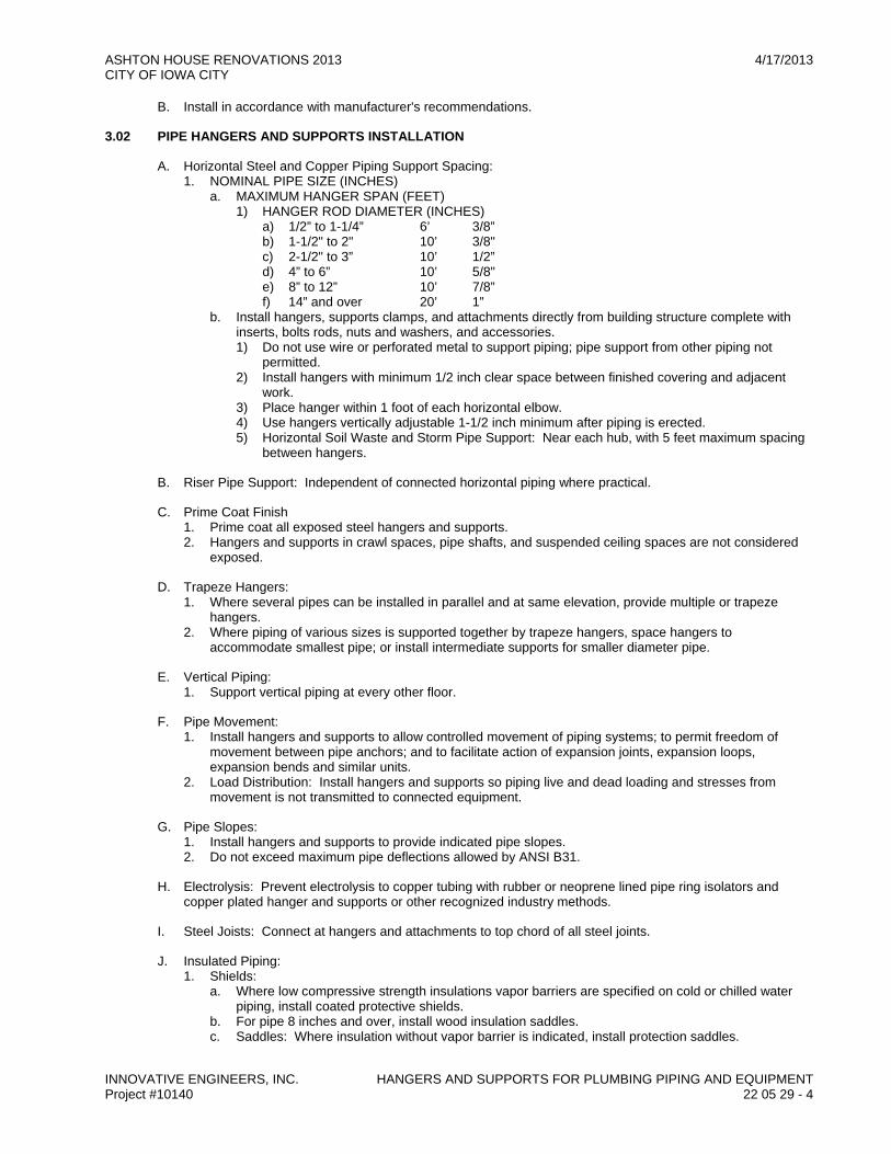
3.02 PIPE HANGERS AND SUPPORTS INSTALLATION
A. Horizontal Steel and Copper Piping Support Spacing: 1. NOMINAL PIPE SIZE (INCHES)
a. MAXIMUM HANGER SPAN (FEET) 1) HANGER ROD DIAMETER (INCHES)
a) 1/2” to 1-1/4” 6’ 3/8” b) 1-1/2" to 2" 10’ 3/8" c) 2-1/2" to 3” 10’ 1/2” d) 4” to 6” 10’ 5/8" e) 8” to 12” 10’ 7/8” f) 14” and over 20’ 1”
b. Install hangers, supports clamps, and attachments directly from building structure complete with inserts, bolts rods, nuts and washers, and accessories. 1) Do not use wire or perforated metal to support piping; pipe support from other piping not
permitted. 2) Install hangers with minimum 1/2 inch clear space between finished covering and adjacent
work. 3) Place hanger within 1 foot of each horizontal elbow. 4) Use hangers vertically adjustable 1-1/2 inch minimum after piping is erected. 5) Horizontal Soil Waste and Storm Pipe Support: Near each hub, with 5 feet maximum spacing
between hangers.
B. Riser Pipe Support: Independent of connected horizontal piping where practical.
C. Prime Coat Finish 1. Prime coat all exposed steel hangers and supports. 2. Hangers and supports in crawl spaces, pipe shafts, and suspended ceiling spaces are not considered
exposed.
D. Trapeze Hangers: 1. Where several pipes can be installed in parallel and at same elevation, provide multiple or trapeze
hangers. 2. Where piping of various sizes is supported together by trapeze hangers, space hangers to
accommodate smallest pipe; or install intermediate supports for smaller diameter pipe.
E. Vertical Piping: 1. Support vertical piping at every other floor.
F. Pipe Movement: 1. Install hangers and supports to allow controlled movement of piping systems; to permit freedom of
movement between pipe anchors; and to facilitate action of expansion joints, expansion loops, expansion bends and similar units.
2. Load Distribution: Install hangers and supports so piping live and dead loading and stresses from movement is not transmitted to connected equipment.
G. Pipe Slopes: 1. Install hangers and supports to provide indicated pipe slopes. 2. Do not exceed maximum pipe deflections allowed by ANSI B31.
H. Electrolysis: Prevent electrolysis to copper tubing with rubber or neoprene lined pipe ring isolators and copper plated hanger and supports or other recognized industry methods.
I. Steel Joists: Connect at hangers and attachments to top chord of all steel joints.
J. Insulated Piping: 1. Shields:
a. Where low compressive strength insulations vapor barriers are specified on cold or chilled water piping, install coated protective shields.
b. For pipe 8 inches and over, install wood insulation saddles. c. Saddles: Where insulation without vapor barrier is indicated, install protection saddles.
ASHTON HOUSE RENOVATIONS 2013 4/17/2013 CITY OF IOWA CITY
INNOVATIVE ENGINEERS, INC. HANGERS AND SUPPORTS FOR PLUMBING PIPING AND EQUIPMENT Project #10140 22 05 29 - 5
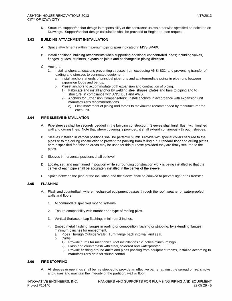
K. Structural support/anchor design is responsibility of the contractor unless otherwise specified or indicated on Drawings. Support/anchor design calculation shall be provided to Engineer upon request.
3.03 BUILDING ATTACHMENT INSTALLATION
A. Space attachments within maximum piping span indicated in MSS SP-69.
B. Install additional building attachments when supporting additional concentrated loads; including valves, flanges, guides, strainers, expansion joints and at changes in piping direction.
C. Anchors: 1. Install anchors at locations preventing stresses from exceeding ANSI B31; and preventing transfer of
loading and stresses to connected equipment. a. Install anchors at ends of principal pipe runs and at intermediate points in pipe runs between
expansion loops and bends. b. Preset anchors to accommodate both expansion and contraction of piping.
1) Fabricate and install anchor by welding steel shapes, plates and bars to piping and to structure; in compliance with ANSI B31 and AWS.
2) Anchors for Expansion Compensators: Install anchors in accordance with expansion unit manufacturer's recommendations. a) Limit movement of piping and forces to maximums recommended by manufacturer for
each unit.
3.04 PIPE SLEEVE INSTALLATION
A. Pipe sleeves shall be securely bedded in the building construction. Sleeves shall finish flush with finished wall and ceiling lines. Note that where covering is provided, it shall extend continuously through sleeves.
B. Sleeves installed in vertical positions shall be perfectly plumb. Provide with special collars secured to the pipes or to the ceiling construction to prevent the packing from falling out. Standard floor and ceiling plates herein specified for finished areas may be used for this purpose provided they are firmly secured to the pipes.
C. Sleeves in horizontal positions shall be level.
D. Locate, set, and maintained in position while surrounding construction work is being installed so that the center of each pipe shall be accurately installed in the center of the sleeve.
E. Space between the pipe or the insulation and the sleeve shall be caulked to prevent light or air transfer.
3.05 FLASHING
A. Flash and counterflash where mechanical equipment passes through the roof, weather or waterproofed walls and floors.
1. Accommodate specified roofing systems.
2. Ensure compatibility with number and type of roofing plies.
3. Vertical Surfaces: Lap flashings minimum 3 inches.
4. Embed metal flashing flanges in roofing or composition flashing or stripping, by extending flanges minimum 6 inches for embedment. a. Pipes Through Outside Walls: Turn flange back into wall and seal. b. Curbs:
1) Provide curbs for mechanical roof installations 12 inches minimum high. 2) Flash and counterflash with steel, soldered and waterproofed. 3) Provide flashing around ducts and pipes passing from equipment rooms, installed according to
manufacturer's data for sound control.
3.06 FIRE STOPPING
A. All sleeves or openings shall be fire stopped to provide an effective barrier against the spread of fire, smoke and gases and maintain the integrity of the partition, wall or floor.
ASHTON HOUSE RENOVATIONS 2013 4/17/2013 CITY OF IOWA CITY
INNOVATIVE ENGINEERS, INC. HANGERS AND SUPPORTS FOR PLUMBING PIPING AND EQUIPMENT Project #10140 22 05 29 - 6
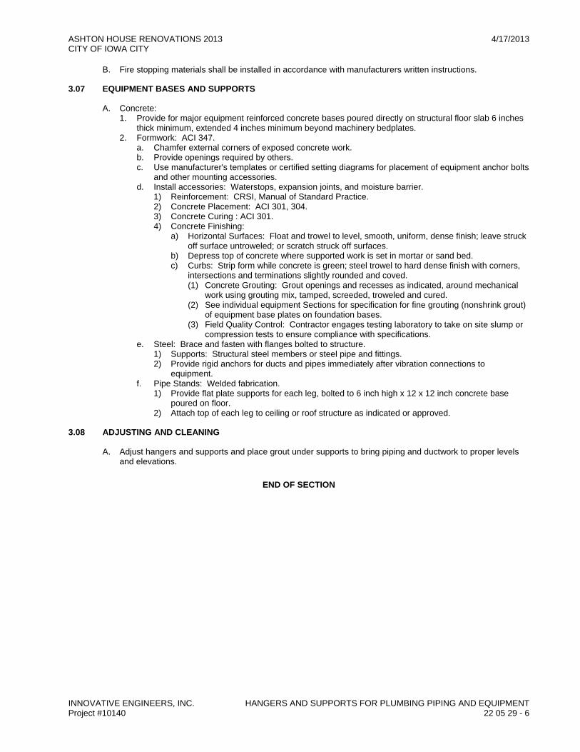
B. Fire stopping materials shall be installed in accordance with manufacturers written instructions.
3.07 EQUIPMENT BASES AND SUPPORTS
A. Concrete: 1. Provide for major equipment reinforced concrete bases poured directly on structural floor slab 6 inches
thick minimum, extended 4 inches minimum beyond machinery bedplates. 2. Formwork: ACI 347.
a. Chamfer external corners of exposed concrete work. b. Provide openings required by others. c. Use manufacturer's templates or certified setting diagrams for placement of equipment anchor bolts
and other mounting accessories. d. Install accessories: Waterstops, expansion joints, and moisture barrier.
1) Reinforcement: CRSI, Manual of Standard Practice. 2) Concrete Placement: ACI 301, 304. 3) Concrete Curing : ACI 301. 4) Concrete Finishing:
a) Horizontal Surfaces: Float and trowel to level, smooth, uniform, dense finish; leave struck off surface untroweled; or scratch struck off surfaces.
b) Depress top of concrete where supported work is set in mortar or sand bed. c) Curbs: Strip form while concrete is green; steel trowel to hard dense finish with corners,
intersections and terminations slightly rounded and coved. (1) Concrete Grouting: Grout openings and recesses as indicated, around mechanical
work using grouting mix, tamped, screeded, troweled and cured. (2) See individual equipment Sections for specification for fine grouting (nonshrink grout)
of equipment base plates on foundation bases. (3) Field Quality Control: Contractor engages testing laboratory to take on site slump or
compression tests to ensure compliance with specifications. e. Steel: Brace and fasten with flanges bolted to structure.
1) Supports: Structural steel members or steel pipe and fittings. 2) Provide rigid anchors for ducts and pipes immediately after vibration connections to
equipment. f. Pipe Stands: Welded fabrication.
1) Provide flat plate supports for each leg, bolted to 6 inch high x 12 x 12 inch concrete base poured on floor.
2) Attach top of each leg to ceiling or roof structure as indicated or approved.
3.08 ADJUSTING AND CLEANING
A. Adjust hangers and supports and place grout under supports to bring piping and ductwork to proper levels and elevations.
END OF SECTION

ASHTON HOUSE RENOVATIONS 2013 4/17/2013 CITY OF IOWA CITY
INNOVATIVE ENGINEERS, INC. IDENTIFICATION FOR PLUMBING PIPING AND EQUIPMENT Project #10140 22 05 53 - 1
SECTION 22 05 53 IDENTIFICATION FOR PLUMBING PIPING AND EQUIPMENT
PART 1 GENERAL
1.01 SECTION INCLUDES
A. Nameplates.
B. Tags.
C. Pipe Markers.
1.02 REFERENCE STANDARDS
A. ASME A13.1 - Scheme for the Identification of Piping Systems; The American Society of Mechanical Engineers; 2007.
1.03 SUBMITTALS
A. List: Submit list of wording, symbols, letter size, and color coding for mechanical identification.
B. Chart and Schedule: Submit valve chart and schedule, including valve tag number, location, function, and valve manufacturer's name and model number.
C. Product Data: Provide manufacturers catalog literature for each product required.
D. Manufacturer's Installation Instructions: Indicate special procedures, and installation.
E. Project Record Documents: Record actual locations of tagged valves.
PART 2 PRODUCTS
2.01 MANUFACTURERS
A. Brady Corporation: www.bradycorp.com.
B. Champion America, Inc: www.Champion-America.com.
C. Seton Identification Products: www.seton.com/aec.
2.02 NAMEPLATES
A. Description: Laminated three-layer plastic with engraved letters. 1. Letter Color: White. 2. Letter Height: 1/4 inch. 3. Background Color: Black.
2.03 TAGS
A. Metal Tags: Brass with stamped letters; tag size minimum 1-1/2 inch diameter with smooth edges.
B. Chart: Typewritten letter size list in anodized aluminum frame.
2.04 PIPE MARKERS
A. Color: Conform to ASME A13.1 or Iowa State University Standards or NFPA 13.
B. Plastic Pipe Markers: Factory fabricated, flexible, semi- rigid plastic, preformed to fit around pipe or pipe covering; minimum information indicating flow direction arrow and identification of fluid being conveyed.
C. Manufacturer: Seton Setmark, Brimar.
ASHTON HOUSE RENOVATIONS 2013 4/17/2013 CITY OF IOWA CITY
INNOVATIVE ENGINEERS, INC. IDENTIFICATION FOR PLUMBING PIPING AND EQUIPMENT Project #10140 22 05 53 - 2
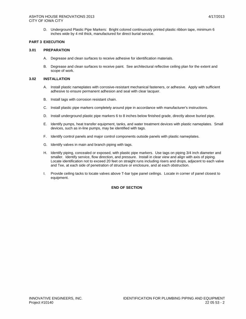
D. Underground Plastic Pipe Markers: Bright colored continuously printed plastic ribbon tape, minimum 6 inches wide by 4 mil thick, manufactured for direct burial service.
PART 3 EXECUTION
3.01 PREPARATION
A. Degrease and clean surfaces to receive adhesive for identification materials.
B. Degrease and clean surfaces to receive paint. See architectural reflective ceiling plan for the extent and scope of work.
3.02 INSTALLATION
A. Install plastic nameplates with corrosive-resistant mechanical fasteners, or adhesive. Apply with sufficient adhesive to ensure permanent adhesion and seal with clear lacquer.
B. Install tags with corrosion resistant chain.
C. Install plastic pipe markers completely around pipe in accordance with manufacturer's instructions.
D. Install underground plastic pipe markers 6 to 8 inches below finished grade, directly above buried pipe.
E. Identify pumps, heat transfer equipment, tanks, and water treatment devices with plastic nameplates. Small devices, such as in-line pumps, may be identified with tags.
F. Identify control panels and major control components outside panels with plastic nameplates.
G. Identify valves in main and branch piping with tags.
H. Identify piping, concealed or exposed, with plastic pipe markers. Use tags on piping 3/4 inch diameter and smaller. Identify service, flow direction, and pressure. Install in clear view and align with axis of piping. Locate identification not to exceed 20 feet on straight runs including risers and drops, adjacent to each valve and Tee, at each side of penetration of structure or enclosure, and at each obstruction.
I. Provide ceiling tacks to locate valves above T-bar type panel ceilings. Locate in corner of panel closest to equipment.
END OF SECTION

ASHTON HOUSE RENOVATIONS 2013 4/17/2013 CITY OF IOWA CITY
INNOVATIVE ENGINEERS, INC. PLUMBING PIPING INSULATION Project #10140 22 07 19 - 1
SECTION 22 07 19 PLUMBING PIPING INSULATION
PART 1 GENERAL
1.01 SECTION INCLUDES
A. Piping insulation.
B. Jackets and accessories.
1.02 REFERENCE STANDARDS
A. ASTM B 209 - Standard Specification for Aluminum and Aluminum-Alloy Sheet and Plate; 2007.
B. ASTM B 209M - Standard Specification for Aluminum and Aluminum-Alloy Sheet and Plate [Metric]; 2007.
C. ASTM C 177 - Standard Test Method for Steady-State Heat Flux Measurements and Thermal Transmission Properties by Means of the Guarded Hot Plate Apparatus; 2004.
D. ASTM C 518 - Standard Test Method for Steady-State Thermal Transmission Properties by Means of the Heat Flow Meter Apparatus; 2004.
E. ASTM C 534 - Standard Specification for Preformed Flexible Elastomeric Cellular Thermal Insulation in Sheet and Tubular Form; 2007a.
F. ASTM C 547 - Standard Specification for Mineral Fiber Pipe Insulation; 2007.
G. ASTM C 585 - Standard Practice for Inner and Outer Diameters of Rigid Thermal Insulation for Nominal Sizes of Pipe and Tubing (NPS System); 1990 (Reapproved 2004).
H. ASTM C 591 - Standard Specification for Unfaced Preformed Rigid Cellular Polyisocyanurate Thermal Insulation; 2007.
I. ASTM C 795 - Standard Specification for Thermal Insulation for Use in Contact with Austenitic Stainless Steel; 2003.
J. ASTM D 2842 - Standard Test Method for Water Absorption of Rigid Cellular Plastics; 2006.
K. ASTM E 84 - Standard Test Method for Surface Burning Characteristics of Building Materials; 2008.
L. ASTM E 96/E 96M - Standard Test Methods for Water Vapor Transmission of Materials; 2005.
M. NFPA 255 - Standard Method of Test of Surface Burning Characteristics of Building Materials; National Fire Protection Association; 2006.
N. UL 723 - Standard for Test for Surface Burning Characteristics of Building Materials; Underwriters Laboratories Inc.; 2003.
1.03 SUBMITTALS
A. Product Data: Provide product description. 1. Indicate complete material data, mastics, and adhesives. 2. List of materials proposed for this project. Indicate thermal characteristics, list of materials, thickness
for each service, and locations. a. Certification:
1) Certification to show compliance with these specifications and governing regulations. 2) Proof of compliance for test of products for fire rating, corrosiveness, and compressive
strength.
1.04 QUALITY ASSURANCE
A. Applicator Qualifications: Company specializing in performing the type of work specified in this section with minimum 3 years of experience.
ASHTON HOUSE RENOVATIONS 2013 4/17/2013 CITY OF IOWA CITY
INNOVATIVE ENGINEERS, INC. PLUMBING PIPING INSULATION Project #10140 22 07 19 - 2
1.05 DELIVERY, STORAGE, AND HANDLING
A. Deliver material to site in factory fabricated containers with manufacturer's stamp or label, showing fire and smoke hazard ratings of products.
B. Accept materials on site, labeled with manufacturer's identification, product density, and thickness.
C. Store material in original wrappings and protect from weather and construction traffic.
D. Protect against sun, dirt, water, chemical and mechanical damage.
E. Remove damaged insulation from project site. Do not install.
PART 2 PRODUCTS
2.01 REQUIREMENTS FOR ALL PRODUCTS OF THIS SECTION
A. Surface Burning Characteristics: Flame spread/Smoke developed index of 25/50, maximum, when tested in accordance with ASTM E 84, NFPA 255, or UL 723.
2.02 GLASS FIBER
A. Manufacturers: 1. Knauf Insulation: www.knaufusa.com. 2. Johns Manville Corporation: www.jm.com. 3. Owens Corning Corp: www.owenscorning.com. 4. CertainTeed Corporation: www.certainteed.com. 5. Insulation: ASTM C 547 and ASTM C 795; rigid molded, noncombustible.
a. 'K' value: ASTM C 177, 0.22 at 75°F. b. Maximum service temperature: 850°F. c. Maximum moisture absorption: 0.2 percent by volume.
6. Vapor Barrier Jacket: White kraft paper with glass fiber yarn, bonded to aluminized film; moisture vapor transmission when tested in accordance with ASTM E 96/E 96M of 0.02 perm-inches.
2.03 FLEXIBLE ELASTOMERIC CELLULAR INSULATION
A. Manufacturer: 1. Armacell International: www.armacell.com. 2. Insulation: Preformed flexible elastomeric cellular rubber insulation complying with ASTM C 534 Grade
1; use molded tubular material wherever possible. a. Minimum Service Temperature: -40°F. b. Maximum Service Temperature: 220°F. c. Connection: Waterproof vapor barrier adhesive.
3. Elastomeric Foam Adhesive: Air dried, contact adhesive, compatible with insulation.
2.04 JACKETS
A. PVC Plastic. 1. Manufacturers:
a. Johns Manville Corporation: www.jm.com. 1) Jacket: One piece molded type fitting covers and sheet material in white color Conform to
ASME 13.1 or ISU Standards a) Minimum Service Temperature: 0°F. b) Maximum Service Temperature: 150°F. c) Moisture Vapor Permeability: 0.002 perm inch, maximum, when tested in accordance with
ASTM E 96/E 96M. d) Thickness: 10 mil. e) Connections: Brush on welding adhesive.

ASHTON HOUSE RENOVATIONS 2013 4/17/2013 CITY OF IOWA CITY
INNOVATIVE ENGINEERS, INC. PLUMBING PIPING INSULATION Project #10140 22 07 19 - 3
PART 3 EXECUTION
3.01 EXAMINATION
A. Verify piping has been tested before applying insulation materials.
B. Verify that surfaces are clean and dry, with foreign material removed.
3.02 INSTALLATION
A. Insulation: Continuous through inside walls and at all hangers; pack insulation around pipes with fireproof self-supporting mineral wool insulation material, fully sealed. 1. Install adhesives at ambient and equipment temperatures recommended by adhesive manufacturer. 2. Fittings:
a. Hot Piping: 1) Do not insulate unions, flanges, strainers, valves, flexible connections, or expansion joints. 2) Terminate insulation neatly with mastic material troweled on bevel. 3) Finish insulation neatly at hangers, supports and other protrusions or interruptions. 4) Ensure hangers and cradles are properly installed to avoid crushing insulation. 5) Locate insulation or cover seams in least visible locations. 6) Cold Piping:
a) Cold Piping: Insulate all fittings, including flanges, all valve bodies and devices, and all air separators associated with cold surfaces. Maintain vapor barrier integrity throughout.
b) Cover fittings, valves, strainers, and flexible connections with equivalent thickness of insulation material.
c) Apply 1 piece PVC cover on fittings and piping. d) Seal lap joints with 100% coverage of vapor barrier sealant and adhesive. e) Seal butt joints with 4 inch wide strips of vapor barrier sealed with vapor barrier adhesive;
or use double self-sealing factory joints. f) Do not use staples on insulation for cold surfaces.
7) Hot Piping: a) Cover fittings with equivalent thickness of insulation material. b) Apply 1-piece PVC cover on fittings and piping.
8) Insulate all condensate drains from equipment. 9) Install protective metal saddles and insulated inserts to prevent insulation compression. 10) Piping exposed to finish areas and in mechanical rooms provide with white PVC jacket covers.
3. Install in accordance with manufacturer's instructions. 4. Glass fiber insulated pipes conveying fluids above ambient temperature:
a. Provide standard jackets, with or without vapor barrier, factory-applied or field-applied. Secure with self-sealing longitudinal laps and butt strips with pressure sensitive adhesive. Secure with outward clinch expanding staples.
b. Insulate fittings, joints, and valves with insulation of like material and thickness as adjoining pipe. Finish with glass cloth and adhesive or PVC fitting covers.
5. Inserts and Shields: a. Application: Piping 1-1/2 inches diameter or larger. b. Shields: Galvanized steel between pipe hangers or pipe hanger rolls and inserts. c. Insert location: Between support shield and piping and under the finish jacket. d. Insert configuration: Minimum 6 inches long, of same thickness and contour as adjoining
insulation; may be factory fabricated. e. Insert material: Hydrous calcium silicate insulation or other heavy density insulating material
suitable for the planned temperature range. 6. Continue insulation through walls, sleeves, pipe hangers, and other pipe penetrations. Finish at
supports, protrusions, and interruptions.
3.03 SCHEDULES
A. Plumbing Systems: 1. Domestic Cold Water:
a. Flexible elastomeric insulation: 1) Pipe Size Range: All
a) Thickness: 1 inch
ASHTON HOUSE RENOVATIONS 2013 4/17/2013 CITY OF IOWA CITY
INNOVATIVE ENGINEERS, INC. PLUMBING PIPING INSULATION Project #10140 22 07 19 - 4
2. Domestic Hot Water: a. Glass Fiber Insulation:
1) Pipe Size Range: 1/2 inch to 1-1/2 inches a) Thickness: 1-1/2 inch
3. Domestic Hot Water Recirculation a. Glass Fiber Insulation:
1) Pipe Size Range: 1/2 inch to 1-1/2 inches a) Thickness: 1-1/2 inch
END OF SECTION

ASHTON HOUSE RENOVATIONS 2013 4/17/2013 CITY OF IOWA CITY
INNOVATIVE ENGINEERS, INC. PLUMBING PIPING Project #10140 22 10 05 - 1
SECTION 22 10 05 PLUMBING PIPING
PART 1 GENERAL
1.01 SECTION INCLUDES
A. Pipe, pipe fittings, valves, and connections for domestic water piping systems.
1.02 REFERENCE STANDARDS
A. ASME B16.1 - Gray Iron Pipe Flanges and Flanged Fittings: Classes 25, 125, and 250; The American Society of Mechanical Engineers; 2005.
B. ASME B16.3 - Malleable Iron Threaded Fittings; The American Society of Mechanical Engineers; 1998 (R2006).
C. ASME B16.4 - Gray Iron Threaded Fittings; The American Society of Mechanical Engineers; 1998 (R2006).
D. ASME B16.18 - Cast Copper Alloy Solder Joint Pressure Fittings; The American Society of Mechanical Engineers; 2001 (R2005) (ANSI B16.18).
E. ASME B16.22 - Wrought Copper and Copper Alloy Solder Joint Pressure Fittings; The American Society of Mechanical Engineers; 2001 (R2005).
F. ASME B16.26 - Cast Copper Alloy Fittings for Flared Copper Tubes; The American Society of Mechanical Engineers; 2006.
G. ASME B16.29 - Wrought Copper and Wrought Copper Alloy Solder Joint Drainage Fittings - DWV; The American Society of Mechanical Engineers; 2001.
H. ASME B31.1 - Power Piping; The American Society of Mechanical Engineers; 2007 (ANSI/ASME B31.1).
I. ASME B31.9 - Building Services Piping; The American Society of Mechanical Engineers; 2004 (ANSI/ASME B31.9).
J. ASME (BPV IV) - Boiler and Pressure Vessel Code, Section IV - Rules for Construction of Heating Boilers; The American Society of Mechanical Engineers; 2007.
K. ASME (BPV IX) - Boiler and Pressure Vessel Code, Section IX - Welding and Brazing Qualifications; The American Society of Mechanical Engineers; 2007.
L. ASTM A 53/A 53M - Standard Specification for Pipe, Steel, Black and Hot-Dipped, Zinc-Coated, Welded and Seamless; 2007.
M. ASTM A 234/A 234M - Standard Specification for Piping Fittings of Wrought Carbon Steel and Alloy Steel for Moderate and High Temperature Service; 2007.
N. ASTM B 32 - Standard Specification for Solder Metal; 2004.
O. ASTM B 42 - Standard Specification for Seamless Copper Pipe, Standard Sizes; 2002.
P. ASTM B 88 - Standard Specification for Seamless Copper Water Tube; 2003.
Q. AWWA C651 - Disinfecting Water Mains; American Water Works Association; 2005 (ANSI/AWWA C651).
R. MSS SP-80 - Bronze Gate, Globe, Angle and Check Valves; Manufacturers Standardization Society of the Valve and Fittings Industry, Inc.; 2003.
S. MSS SP-110 - Ball Valves Threaded, Socket-Welding, Solder Joint, Grooved and Flared Ends; Manufacturers Standardization Society of the Valve and Fittings Industry, Inc.; 1996.

ASHTON HOUSE RENOVATIONS 2013 4/17/2013 CITY OF IOWA CITY
INNOVATIVE ENGINEERS, INC. PLUMBING PIPING Project #10140 22 10 05 - 2
1.03 SUBMITTALS
A. Product Data: Provide data on pipe materials, pipe fittings, valves, and accessories. Provide manufacturers catalog information. Indicate valve data and ratings.
B. Project Record Documents: Record actual locations of valves.
1.04 QUALITY ASSURANCE
A. Valves: Manufacturer's name and pressure rating marked on valve body. Valves shall be manufactured in the United States of America
B. Welding Materials and Procedures: Conform to ASME (BPV IX) and applicable state labor regulations.
C. Identify pipe with marking including size, ASTM material classification, ASTM specification, potable water certification, water pressure rating.
1.05 REGULATORY REQUIREMENTS
A. Perform Work in accordance with State of Iowa plumbing code.
B. Conform to applicable code for installation of backflow prevention devices.
1.06 DELIVERY, STORAGE, AND HANDLING
A. Accept valves on site in shipping containers with labeling in place. Inspect for damage.
B. Provide temporary end caps and closures on piping and fittings. Maintain in place until installation.
C. Protect piping systems from entry of foreign materials by temporary covers, completing sections of the work, and isolating parts of completed system.
PART 2 PRODUCTS
2.01 DOMESTIC WATER PIPING, ABOVE GRADE
A. Copper Tube: ASTM B 88 (ASTM B 88M), Type L (B), Drawn (H). 1. Fittings: ASME B16.18, cast copper alloy or ASME B16.22, wrought copper and bronze. 2. Joints: ASTM B 32, alloy Sn95 solder.
2.02 FLANGES, UNIONS, AND COUPLINGS
A. Flanges for Pipe Size Over 1 Inch: 1. Ferrous pipe: Class 150 malleable iron threaded or forged steel slip-on flanges; preformed neoprene
gaskets. 2. Copper tube and pipe: Class 150 slip-on bronze flanges; preformed neoprene gaskets.
B. Dielectric Connections: Union with galvanized or plated steel threaded end, copper solder end, water impervious isolation barrier.
2.03 VALVES IN WATER LINES
A. Check Valves 2.5 Inches Diameter and Smaller: Class 125 # SWP, 200 # WOG, horizontal swing check, body and cap shall be of ASTM B62 cast bronze, TFE disc, integral bronze seats, MSS SP-80.
B. Ball Valves 3 Inches Diameter and Smaller: 600 # WOG, 150 # SWP, 2 piece body style, CP brass tunneled ball, reinforced TFE seats, hex gland follower, bronze body of ASTM B584, blow-out proof stem, lever handle.
2.04 RELIEF VALVES
A. Pressure Relief: 1. AGA Z21.22 certified, bronze body, teflon seat, steel stem and springs, automatic, direct pressure
actuated, ASME rated.
ASHTON HOUSE RENOVATIONS 2013 4/17/2013 CITY OF IOWA CITY
INNOVATIVE ENGINEERS, INC. PLUMBING PIPING Project #10140 22 10 05 - 3
2.05 STRAINERS
A. Manufacturers: 1. Armstrong International, Inc: www.armstronginternational.com. 2. Green Country Filtration: greencountryfiltration.com. 3. WEAMCO: www.weamco.com.
B. Size 2 inch and Under: 1. Threaded brass body for 175 psi CWP, Y pattern with 1/32 inch stainless steel perforated screen. 2. Class 150, threaded bronze body 300 psi CWP, Y pattern with 1/32 inch stainless steel perforated
screen.
C. Strainers must be rated acceptable for domestic water service.
PART 3 EXECUTION
3.01 PREPARATION
A. Ream pipe and tube ends. Remove burrs. Bevel plain end ferrous pipe.
B. Remove scale and dirt, on inside and outside, before assembly.
C. Prepare piping connections to equipment with flanges or unions.
3.02 INSTALLATION
A. Install in accordance with manufacturer's instructions.
B. Provide non-conducting dielectric connections wherever jointing dissimilar metals.
C. Route piping in orderly manner and maintain gradient. Route parallel and perpendicular to walls.
D. Install piping to maintain headroom, conserve space, and not interfere with use of space.
E. Group piping whenever practical at common elevations.
F. Provide clearance in hangers and from structure and other equipment for installation of insulation and access to valves and fittings.
G. Provide access where valves and fittings are not exposed. Coordinate size and location of access doors.
H. Install vent piping penetrating roofed areas to maintain integrity of roof assembly.
I. Provide support for utility meters in accordance with requirements of utility companies.
J. Prepare exposed, unfinished pipe, fittings, supports, and accessories ready for finish painting.
K. Install valves with stems upright or horizontal, not inverted.
L. Install water piping to ASME B31.9.
3.03 EXECUTION
A. Workmanship 1. Piping shown on Drawings shall be installed complete and shall be of size shown on Drawings. When a
size is not indicated, request pipe size from Engineer. 2. All vertical offsets shall have a drip leg full size of pipe and a minimum of 6 inches long. 3. All piping shall be installed parallel or perpendicular to the building construction. 4. All piping shall be installed to allow for expansion. 5. Perform all work in accordance with State of Iowa Plumbing Code.
B. Joints 1. All pipe shall be reamed to full pipe diameter before joining. 2. Joints may be sweat or screwed.

ASHTON HOUSE RENOVATIONS 2013 4/17/2013 CITY OF IOWA CITY
INNOVATIVE ENGINEERS, INC. PLUMBING PIPING Project #10140 22 10 05 - 4
3. Screwed joints shall be made with standard pipe thread and approved compound applied to male thread only.
4. Use only shaped nipples, welding laterals, or saddle fittings for intersection welding of branches to mains. 5. Valves and specialties shall have screwed or flanged joints.
C. Testing 1. Entire system shall be tested per international plumbing code. 2. Owner or Owner's representative to be present for all testing and provide final signature of acceptance. 3. See system startup.
D. Sectionalized 1. Pipe may be tested a section at a time in order to facilitate construction. Contractor will provide
necessary fittings to accomplish testing.
E. Protection 1. Piping shall be protected at all times from dirt and moisture. 2. During storage on job site or construction, keep pipe ends plugged or capped to prevent dirt or moisture
from entering the pipe.
3.04 APPLICATION
A. Install unions downstream of valves and at equipment or apparatus connections.
B. Install ball valves for shut-off and to isolate equipment, part of systems, or vertical risers.
3.05 DISINFECTION OF DOMESTIC WATER PIPING SYSTEM
A. Prior to starting work, verify system is complete, flushed and clean.
B. Ensure Ph of water to be treated is between 7.4 and 7.6 by adding alkali (caustic soda or soda ash) or acid (hydrochloric).
C. Inject disinfectant, free chlorine in liquid, powder, tablet or gas form, throughout system to obtain 50 to 80 mg/L residual.
D. Bleed water from outlets to ensure distribution and test for disinfectant residual at minimum 15 percent of outlets.
E. Maintain disinfectant in system for 24 hours.
F. If final disinfectant residual tests less than 25 mg/L, repeat treatment.
G. Flush disinfectant from system until residual equal to that of incoming water or 1.0 mg/L.
H. Take samples no sooner than 24 hours after flushing, from 2 percent of outlets and from water entry, and analyze in accordance with AWWA C651.
END OF SECTION
ASHTON HOUSE RENOVATIONS 2013 4/17/2013 CITY OF IOWA CITY
INNOVATIVE ENGINEERS, INC. NATURAL GAS PIPING Project #10140 22 11 23 - 1
SECTION 22 11 23 NATURAL GAS PIPING
PART 1 GENERAL
1.01 SECTION INCLUDES
A. Natural gas pipe and pipe fittings.
1.02 REFERENCE STANDARDS
A. Gas piping and connections to equipment shall be in accordance with NFPA-54, City of Iowa City Gas Code, and local utility company.
1.03 SUBMITTALS
A. Product Data: Provide manufacturers catalogue information. 1. Pipe materials. 2. Pipe fittings
1.04 REGULATORY REQUIREMENTS
A. Conform to ASME B31.9 and ASME B31.1 code for installation of piping system.
1.05 DELIVERY, STORAGE, AND HANDLING
A. Provide factory-applied plastic end-caps on each length of pipe and tube. Maintain end-caps through shipping, storage, and handling as required to prevent pipe-end damage and eliminate dirt and moisture from inside of pipe and tube.
B. Where possible, store pipe and tube inside and protected from weather. Where necessary to store outside, elevate well above grade and enclose with durable, waterproof wrapping.
C. Protect flanges and fittings from moisture and dirt by inside storage and enclosure, or by packaging with durable, waterproof wrapping.
PART 2 PRODUCTS
2.01 NATURAL GAS PIPING
A. Steel Pipe: ASTM A106 Carbon Steel, seamless black pipe.
B. Flexible Stainless Steel Piping: ASTM A240 Stainless Steel tubing with fire-retardant polyethylene plastic jacket.
PART 3 EXECUTION
3.01 PREPARATION
A. Ream pipe and tube ends. Remove burrs. Bevel plain end ferrous pipe.
B. Remove scale and dirt on inside and outside before assembly.
C. Prepare piping connections to equipment with flanges or unions.Keep open ends of pipe free from scale and dirt.
D. Whenever work is suspended during construction protect open ends with temporary plugs or caps.
E. After completion, fill, clean and treat systems.
3.02 INSTALLATION
A. Comply with requirements of ANSI Z 223.l, and in accordance with recognized industry practices to insure that products serve intended functions.
ASHTON HOUSE RENOVATIONS 2013 4/17/2013 CITY OF IOWA CITY
INNOVATIVE ENGINEERS, INC. NATURAL GAS PIPING Project #10140 22 11 23 - 2
B. Install in accordance with manufacturer's instructions.
C. Route piping in orderly manner, plumb and parallel to building structure, and maintain gradient.
D. Install piping to conserve building space and avoid interference with use of space.
E. Install gas shutoff plug valve in main, in each branch line and at each appliance.
F. Install service plug valve at each outlet.
G. Use sealants on metal gas piping threads that are chemically resistant to LP and natural gas. Use sealants sparingly and apply to only male threads of metal joints.
H. Remove cutting and threading burrs before assembling piping.
I. Do not install defective piping or fittings. Do not use pipe with threads that are chipped, stripped or damaged.
J. Plug each gas outlet, including valves, with a threaded plug or cap immediately after installation, andretain until continuing piping or equipment connections are completed.
K. Install dirt-legs in gas piping at connections to equipment and elsewhere as indicated, and where required by code or regulation.
L. Install tee fittings with bottom outlet plugged, or capped, at bottom of pipe risers.
M. Use dielectric unions where dissimilar metals are joined together.
N. Install piping with 1/64" per foot (1/8%) downward slope in direction flow.
O. Installation of Valves:
P. Gas Cocks: Provide at connection to gas train for each gas-fired equipment item; and on risers and braces where indicated. 1. Locate gas cocks where easily accessible, and where they will be protected from possible injury. 2. Install valves with stems upright or horizontal, not inverted.
3.03 PIPE TESTING
A. Prior to initial operation: Test and purge fuel gas piping in accordance with ANSI Z 223.I, National Fuel Gas Code.
B. Piping Tests: 1. Using dry nitrogen, purge each segment to be tested. Cap or otherwise seal the segment to be tested.
Fill system with dry nitrogen and test in accordance with NFPA 54. 2. Repair or replace fuel gas piping as required to eliminate leaks, and retest as specified to demonstrate
compliance. 3. All welded pipe shall be pressure tested to 100 psig for a minimum period of one hour. Isolate
equipment from piping during this test. Submit test results.
C. Purge System: 1. After all segments have been tested and entire system completed, purge the system free of air in
accordance with NFPA 54. Do not leave purge discharge points unattended.
END OF SECTION
ASHTON HOUSE RENOVATIONS 2013 4/17/2013 CITY OF IOWA CITY
INNOVATIVE ENGINEERS, INC. PLUMBING FIXTURES Project #10140 22 40 00 - 1
SECTION 22 40 00 PLUMBING FIXTURES
PART 1 GENERAL
1.01 SECTION INCLUDES
A. Mop (Utility) Faucet.
B. Tankless Natural Gas Water Heater.
1.02 REFERENCE STANDARDS
A. ASME A112.18.1 - Plumbing Supply Fittings; The American Society of Mechanical Engineers; 2005.
B. ASME Z21.10.3/CSA 4.3-2011 Gas Water Heaters – Volume III.
1.03 SUBMITTALS
A. Product Data: Provide catalog illustrations of fixtures, sizes, rough-in dimensions, utility sizes, trim, and finishes.
B. Maintenance Data: Include fixture trim exploded view and replacement parts lists.
C. Warranty: Submit manufacturer warranty and ensure forms have been completed in Iowa State University's name and registered with manufacturer.
1.04 DELIVERY, STORAGE, AND HANDLING
A. Accept fixtures on site in factory packaging. Inspect for damage.
B. Protect installed fixtures from damage by securing areas and by leaving factory packaging in place to protect fixtures and prevent use.
PART 2 PRODUCTS
2.01 MOP (UTILITY) FAUCET
A. Acceptable manufacturers: 1. American Standard 8344.012 2. Chicago Faucet 3. Aqua-Spec 4. Approved equivalent.
B. Exposed yoke, wall-mount utility type with lever handles, spout wall brace, vacuum breaker spout, hose end spout, integral supply stops. Rough chrome finish.
2.02 TANKLESS NATURAL GAS WATER HEATER
A. Acceptable manufacturers: 1. Navien NPE-240A. 2. Approved equivalent.
B. Type: Factory-assembled and wired, natural gas instantaneous water heater domestic hot water with stainless steel heat exchanger in carbon steel casing with integral micro-processor controls.
C. Performance: 1. Outlet (Hot) water temperature: 120°F, minimum. 2. Outlet temperature accuracy: +/- 1%. 3. Capacity: 5 gpm. 4. Built in buffer tank and recirculation pump.

ASHTON HOUSE RENOVATIONS 2013 4/17/2013 CITY OF IOWA CITY
INNOVATIVE ENGINEERS, INC. PLUMBING FIXTURES Project #10140 22 40 00 - 2
D. Fuel Characteristics: 1. Natural Gas. 2. Heat input: 19,900-199,000 Btu/hr.
E. Electrical Characteristics: 120 volts, single phase, 60 Hz.; 2 Amps, max.
F. Connections: 1. Cold Water: 3/4". 2. Hot Water: 3/4". 3. Natural Gas: 3/4”. 4. Intake Air: 2” or 3”. 5. Vent: 2” or 3”.
PART 3 EXECUTION
3.01 INSTALLATION
A. Install components level and plumb.
B. Install and secure fixtures in place with wall supports and bolts.
C. Solidly attach water heater to wall.
3.02 CLEANING AND ADJUSTING
A. After plumbing fixtures have been installed, the fixtures and trimmings shall be thoroughly cleaned of all grease, oil, dirt, labels and stickers, and other foreign matter, and all packing materials shall be promptly removed from the premises. All valves and faucets shall be adjusted to suit the operating water pressure and all work maintained in clean and proper operating condition until accepted by the Architect/Engineer.
B. Following completion of installation, clean all construction dirt dust, and debris from all plumbing fixtures. Verify that all flow or temperature settings have been made where required and that all necessary electrical connections are powered up.
C. Protect installed products from damage due to subsequent construction operations.
3.03 SCHEDULES
A. Fixture Heights: Install fixtures to heights above finished floor as indicated. 1. Mop (Utility) Faucet:
a. Standard: 32 inches to bottom of spout. 2. Tankless Natural Gas Water Heater:
a. Standard: 44 inches to bottom of head.
B. Fixture Rough-In 1. Mop (Utility) Faucet:
a. Hot Water: 1/2 Inch. b. Cold Water: 1/2 Inch.
END OF SECTION

ASHTON HOUSE RENOVATIONS 2013 4/17/2013 CITY OF IOWA CITY
INNOVATIVE ENGINEERS, INC. COMMON WORK RESULTS FOR HVAC Project #10140 23 05 00 - 1
SECTION 23 05 00 COMMON WORK RESULTS FOR HEATING, VENTILATING & AIR CONDITIONING
PART 1 GENERAL
1.01 SECTION INCLUDES
A. Work to be performed under this Division shall include all labor, materials, equipment, transportation, construction plant and facilities necessary to provide a complete and satisfactory system ready to use. Examine all drawings and all sections of specifications to ascertain to what extent other contracts affect work.
1.02 QUALITY ASSURANCE
A. Qualifications of contractor: All materials and equipment shall be new and all work shall be executed with maximum speed consistent with current accepted trade practices. Furnish materials and equipment promptly after authorization to proceed, and proceed with work in progress with contractor on project. Perform all work included in contract in a manner that will not cause interferences or delays to, or interfere with, progress of contractor.
B. Requirements of regulatory agencies: 1. Permits: Arrange and pay for all permits, inspections and utility connections required. 2. Referenced standards:
a. Comply with specified codes and standards. If conflict exists between codes or standards and drawings, project manual or addenda requirements, request clarification from Architect/Engineer.
b. Conform to installation rules and regulations of standards listed including all subsequently published amendments thereto issued prior to date of bidding documents.
c. Conform to requirements of all local, state and federal agencies, which have authority over this project. Include all items of labor and material required to meet such requirements regardless of failure to specify in project manual or indicate on drawings each individual item.
d. All equipment, apparatus and systems shall be rated, tested, fabricated and installed with applicable industry standards.
e. Applicable portions of latest editions of following standards form a part of this project manual to same force and effect as if repeated herein. 1) American Gas Association, Inc. (AGA) 2) American Society for Testing Materials (ASTM) 3) American Society of Heating, Refrigeration, and Air Conditioning Engineers (ASHRAE) 4) American Society of Mechanical Engineers (ASME) 5) American Water Works Association (AWWA) 6) National Electrical Code (NEC) 7) National Electric Manufacturers Association (NEMA) 8) National Fire Protection Association (NFPA) 9) Sheet Metal and Air Conditioning Contractors National Association, Inc. (SMACNA) 10) Underwriters Laboratories, Inc. (UL) 11) Environmental Protection Agency (EPA) 12) Department of Public Health (DPH) 13) Iowa Plumbing Code, Current Edition
1.03 COORDINATION & SUBMITTALS
A. Contractor shall resolve all conflicts before actual installation begins. Order of space preference throughout building shall be: 1. Recessed light fixtures 2. Duct work 3. Soil, waste, vent and storm piping 4. Domestic water piping 5. Sprinkler piping 6. Electrical conduit 7. Exception: Plumbing lines below or behind plumbing fixtures shall have precedence over all other work.
Electrical conduit above or below switchgear, panel boards and control panels shall have precedence over all other work. Do not install any fluid conveying piping over electrical or elevator equipment.
8. Submit following Certifications: a. Fire Protection
ASHTON HOUSE RENOVATIONS 2013 4/17/2013 CITY OF IOWA CITY
INNOVATIVE ENGINEERS, INC. COMMON WORK RESULTS FOR HVAC Project #10140 23 05 00 - 2
b. Welding c. Insulation d. Air & Water Balance e. Domestic Water Disinfection
1.04 STARTING, TESTING, ADJUSTING & BALANCING
A. See sections 23 05 93 Testing, Adjusting, and Balancing
1.05 WARRANTY
A. Guarantee all work including labor, material and equipment for this project for a period of one (1) year from date of acceptance by Owner.
PART 2 PRODUCTS – NOT USED
PART 3 EXECUTION
3.01 EXISTING CONDITIONS
A. In order to become familiar with scope of work involved, visit existing site, before submitting bid, and carefully examine existing condition in order to have full knowledge and understanding of conditions and restrictions affecting performance of work required. Include in bid all work which is reasonably inferred by contract drawings and specifications, whether specifically shown or not, as a result of existing conditions, construction, irregularities and interferences which may affect work. No additional compensation will be considered for misunderstanding conditions to be met.
B. Layout shown on drawings is necessarily diagrammatic but shall be followed as closely as other work will permit. Changes from these drawings required to make this work conform to building construction shall be made only with prior written approval of Architect/Engineer. All proposed changes shall be shown on shop drawings. All measurements shall be verified by actual observation and all work shall fit in place meeting approval of Architect/Engineer.
C. Contractor shall provide openings required in new and existing construction that may be necessary for installation of mechanical work and all patching and workmen competent in trade required, at expense of contractor shall do repairing. Contractor shall be responsible for arranging work so that minimum cutting will be required. All rubbish and excess materials involved in such cutting shall be promptly removed from site and disposed of by contractor. Cutting through floor or roof systems or load bearing walls shall be done only with prior written approval of Architect/Engineer so as to avoid damaging structural system.
D. Sequencing, scheduling: 1. Confer with contractor regarding location and size of pipes, equipment, ducts, openings and special
architectural treatments in order that there may be no interferences between installation or progress of work of contractor on project. order of space preference shall be as listed above.
2. In case of interconnection of work of two or more contractors, verify at site or on shop drawings all dimensions relating to such work. All errors due to failure to so verify any such dimensions shall be promptly rectified.
3. All line voltage wiring and final connections to complete mechanical systems shall be provided by Electrical Contractor. All electrical conduit, wire, and connections relating to mechanical equipment controls and all wiring associated with starter holding coils, shall be responsibility of contractor installing mechanical equipment unless otherwise indicated on drawings. Contractor installing mechanical equipment shall be responsible for magnetic motor starters where such starters are part of control package of equipment supplied. All other starters shall be furnished and installed by Electrical Contractor. Contractor installing starters that are part of a control package shall coordinate starter requirements with Division 26 of specifications.
4. Access panels, in walls or ceilings, required for access and maintenance (i.e., automatic or manual damper, fire or smoke damper, coil or control instrument mounted in a duct or pipe) shall be provided by respective contractor. Access panels are not required in areas where ceiling system is lay-in tile; however, sufficient space must be available in and through ceiling system to allow maintenance and adjustment of dampers, and cleaning of coils as necessary, or a suitable access panel shall be provided for that purpose. Access panels shall be approximately 15 inches by 18 inches wherever possible and shall be provided with flush trim and an allenkey operated camlock fastener. Karp, Milcor, or Bilco shall manufacture panels.
ASHTON HOUSE RENOVATIONS 2013 4/17/2013 CITY OF IOWA CITY
INNOVATIVE ENGINEERS, INC. COMMON WORK RESULTS FOR HVAC Project #10140 23 05 00 - 3
5. Items of equipment may be specified in singular however, provide and install number of items of equipment as indicated on drawings and as required for a complete system.
6. Each contractor shall provide excavating, pumping, backfilling, and compacting required for installation of their respective work as shown on drawings.
7. Equipment and devices furnished and installed by mechanical contractors, which have factory prime coat, or final surface finish shall be replaced, repaired or refinished if defective or damaged during installation.
8. Arrange all work so a minimum period of interruption or outages will occur in temporary or permanent transfer of services as required for all mechanical revisions. Not less than 48 hours notification to Owner shall be required before approval will be granted for any disruption of gas, water, or sanitary services. Outage request shall include extent of work to be done, length of outage time required, and time at which outage is to begin. No allowance will be made for extra payment as a result of scheduling “overtime” work necessary to perform before or after normal or regular working hours to accomplish work intended.
9. Submit a “Sequence of Work Schedule” in respect to all temporary and permanent utility and service cutovers after final determination. This schedule shall be submitted for approval to Architect/Engineer. Submittal shall designate priority order, service or utility affected, date of cutover, and time of day to start and finish.
3.02 CLEANING
A. Upon completion of contract all remaining materials and rubbish shall be removed from building and premises and work areas shall be left clean and free from stains, mortar, paint spots, etc.
B. All switches, controls, and safety devices shall be clearly and permanently marked with embossed or printed plates as to purpose and as to operation and shall be tested in presence of Owner's designated representative to insure that their function and purpose is understood.
C. Upon completion of work, put systems into service maintaining responsibility for equipment during all testing operations including lubricating and turning on and off of such apparatus.
END OF SECTION

ASHTON HOUSE RENOVATIONS 2013 4/17/2013 CITY OF IOWA CITY
INNOVATIVE ENGINEERS, INC. COMMON WORK RESULTS FOR HVAC Project #10140 23 05 00 - 4
THIS PAGE
INTENTIONALLY
LEFT BLANK

ASHTON HOUSE RENOVATIONS 2013 4/17/2013 CITY OF IOWA CITY
INNOVATIVE ENGINEERS, INC. COMMON MOTOR REQUIREMENTS FOR HVAC EQUIPMENT Project #10140 23 05 13 - 1
SECTION 23 05 13 COMMON MOTOR REQUIREMENTS FOR HVAC EQUIPMENT
PART 1 GENERAL
1.01 SECTION INCLUDES
A. Single phase electric motors.
1.02 SUBMITTALS
A. Product Data: Provide wiring diagrams with electrical characteristics and connection requirements.
B. Test Reports: Indicate test results verifying nominal efficiency and power factor for three phase motors larger than 1/2 horsepower.
C. Manufacturer's Installation Instructions: Indicate setting, mechanical connections, lubrication, and wiring instructions.
D. Operation Data: Include instructions for safe operating procedures.
E. Maintenance Data: Include assembly drawings, bearing data including replacement sizes, and lubrication instructions.
1.03 QUALITY ASSURANCE
A. Conform to NFPA 70.
1.04 DELIVERY, STORAGE, AND HANDLING
A. Protect motors stored on site from weather and moisture by maintaining factory covers and suitable weather-proof covering. For extended outdoor storage, remove motors from equipment and store separately.
PART 2 PRODUCTS
2.01 GENERAL CONSTRUCTION AND REQUIREMENTS
A. Electrical Service: 1. Motors 1/2 HP and Smaller: 115 volts, single phase, 60 Hz. 2. Motors 3/4 horsepower and larger or motors used in outdoor application (regardless of horsepower)
shall be three phase, 60 Hertz. 3. Motors configured in duplex applications shall have an individual electrical circuit to each motor. 4. Motor starter coils and control circuits shall be powered by 120 volt control transformers located within
the motor started enclosure.
B. Construction: 1. Open drip-proof type except where specifically noted otherwise. 2. Motors shall be of Cast Iron Construction. 3. Design for continuous operation in 40 °C environment. 4. Design for temperature rise in accordance with NEMA MG 1 limits for insulation class, service factor,
and motor enclosure type.
C. All motors furnished shall be the manufacturer's premium efficiency design. The nominal efficiency and the minimum guaranteed efficiency shall be stamped on the nameplate of the motor. All efficiency testing and labeling shall be done in accordance with the NEMA MG 1 standard.
D. Explosion-proof motors must be UL approved and labeled for hazard classification, with over temperature protection.
E. Visible nameplates must be stainless steel, indicating motor horsepower, voltage, phase, cycles, RPM, full load amps, locked rotor amps, frame size, manufacturer's name and model number, service factor, power factor, and efficiency.

ASHTON HOUSE RENOVATIONS 2013 4/17/2013 CITY OF IOWA CITY
INNOVATIVE ENGINEERS, INC. COMMON MOTOR REQUIREMENTS FOR HVAC EQUIPMENT Project #10140 23 05 13 - 2
F. Wiring Terminations 1. Motor leads shall be stranded copper and shall be permanently identified and brought out into the motor
terminal box through a neoprene gasket. Conduit opening suitable for locknut type connector. Include UL listed ground lug in terminal enclosure.
2. For fractional horsepower motors where connection is made directly, provide conduit opening suitable for locknut type fitting in end frame.
2.02 SINGLE PHASE POWER - SPLIT PHASE MOTORS
A. Starting Torque: Less than 150 percent of full load torque.
B. Starting Current: Up to seven times full load current.
C. Breakdown Torque: Approximately 200 percent of full load torque.
D. Drip-proof Enclosure: Class A (50°C temperature rise) insulation, NEMA Service Factor, prelubricated sleeve or ball bearings.
E. Enclosed Motors: Class A (50°C temperature rise) insulation, 1.0 Service Factor, prelubricated ball bearings.
2.03 SINGLE PHASE POWER - CAPACITOR START MOTORS
A. Starting Torque: Three times full load torque.
B. Starting Current: Less than five times full load current.
C. Pull-up Torque: Up to 350 percent of full load torque.
D. Breakdown Torque: Approximately 250 percent of full load torque.
E. Motors: Capacitor in series with starting winding; provide capacitor-start/capacitor-run motors with two capacitors in parallel with run capacitor remaining in circuit at operating speeds.
F. Drip-proof Enclosure: Class A (50°C temperature rise) insulation, NEMA Service Factor, prelubricated sleeve bearings.
G. Enclosed Motors: Class A (50°C temperature rise) insulation, 1.0 Service Factor, prelubricated ball bearings.
PART 3 EXECUTION
3.01 APPLICATION
A. Single phase motors for shaft mounted fans or blowers: Permanent split capacitor type.
B. Motors located in exterior locations: Totally closed type.
3.02 INSTALLATION
A. Install in accordance with manufacturer's instructions.
B. Install securely on firm foundation. Mount ball bearing motors with shaft in any position.
C. Check line voltage and phase and ensure agreement with nameplate.
3.03 MOTOR DYNAMIC BALANCING
A. Perform dynamic balancing and test motors for vibration after manufacture. Self excite vibration velocity of motor shall not exceed 0.157/0.06 inches per second at the bearing caps.
3.04 STARTUP
A. Inspect, test and start each motor and align with a dial indicator to 0.002"
END OF SECTION

ASHTON HOUSE RENOVATIONS 2013 4/17/2013 CITY OF IOWA CITY
INNOVATIVE ENGINEERS, INC. METERS AND GAGES FOR HVAC Project #10140 23 05 19 - 1
SECTION 23 05 19 METERS AND GAGES FOR HVAC
PART 1 GENERAL
1.01 SECTION INCLUDES
A. Positive displacement meters.
B. Pressure gages and pressure gage taps.
C. Thermometers and thermometer wells.
D. Static pressure gages.
1.02 REFERENCES
A. ASME B40.100 - Pressure Gauges and Gauge Attachments; The American Society of Mechanical Engineers; 2005.
B. ASTM E 1 - Standard Specification for ASTM Thermometers; 2005.
C. ASTM E 77 - Standard Test Method for Inspection and Verification of Thermometers; 1998 (Reapproved 2003).
D. AWWA C700 - Cold Water Meters -- Displacement Type, Bronze Main Case; American Water Works Association; 2002 (ANSI/AWWA C700).
E. AWWA C706 - Direct-Reading, Remote-Registration Systems for Cold Water Meters; American Water Works Association; 1996 (R 2005) (ANSI/AWWA C706).
F. AWWA M6 - Water Meters -- Selection, Installation, Testing, and Maintenance; American Water Works Association; 1999.
G. UL 393 - Indicating Pressure Gauges for Fire-Protection Service; Underwriters Laboratories Inc.; 2005.
1.03 SUBMITTALS
A. Product Data: Provide list that indicates use, operating range, total range and location for manufactured components.
1.04 FIELD CONDITIONS
A. Do not install instrumentation when areas are under construction, except for required rough-in, taps, supports and test plugs.
PART 2 PRODUCTS
2.01 POSITIVE DISPLACEMENT METERS (LIQUID)
A. Manufacturers: 1. Dwyer Instruments, Inc: www.dwyer-inst.com. 2. Venture Measurement Company: www.venturemeasurement.com. 3. McCrometer: www.mccrometer.com.
B. AWWA C700, positive displacement disc type suitable for fluid with bronze case and cast iron frost-proof, breakaway bottom cap, hermetically sealed register, remote reading to AWWA C706.
C. Meter: Brass body turbine meter with magnetic drive register.
2.02 PRESSURE GAGES
A. Manufacturers: 1. Dwyer Instruments, Inc: www.dwyer-inst.com.

ASHTON HOUSE RENOVATIONS 2013 4/17/2013 CITY OF IOWA CITY
INNOVATIVE ENGINEERS, INC. METERS AND GAGES FOR HVAC Project #10140 23 05 19 - 2
2. Moeller Instrument Co., Inc: www.moellerinstrument.com. 3. Omega Engineering, Inc: www.omega.com.
B. Pressure Gages: ASME B40.100, UL 393 drawn steel case, phosphor bronze bourdon tube, rotary brass movement, brass socket, with front recalibration adjustment, black scale on white background. 1. Case: Cast aluminum with phosphor bronze bourdon tube. 2. Size: 4-1/2 inch diameter. 3. Mid-Scale Accuracy: One percent. 4. Scale: Psi.
2.03 PRESSURE GAGE TAPPINGS
A. Gage Cock: Shall be 1/4 turn ballvalave with 1/4" NPT female threads and lever or T handle. They shall be rated for sevice at 600 # WOG.
2.04 STEM TYPE THERMOMETERS
A. Manufacturers: 1. Dwyer Instruments, Inc: www.dwyer-inst.com. 2. Omega Engineering, Inc: www.omega.com. 3. Weksler Glass Thermometer Corp: www.wekslerglass.com.
B. Thermometers - Adjustable Angle: Red- or blue-appearing non-toxic liquid in glass; ASTM E 1; lens front tube, cast aluminum case with enamel finish, cast aluminum adjustable joint with positive locking device; adjustable 360° in horizontal plane, 180° in vertical plane. 1. Size: 7 inch scale. 2. Window: Clear glass. 3. Stem: 3/4 inch NPT brass. 4. Accuracy: 2 percent, per ASTM E 77. 5. Calibration: °F.
2.05 DIAL THERMOMETERS
A. Manufacturers:
1. Dwyer Instruments, Inc: www.dwyer-inst.com. 2. Omega Engineering, Inc: www.omega.com. 3. Weksler Glass Thermometer Corp: www.wekslerglass.com.
B. Thermometer: ASTM E 1, stainless steel case, adjustable angle with front recalibration, bimetallic helix actuated with silicone fluid damping, white with black markings and black pointer hermetically sealed lens, stainless steel stem. 1. Size: 3 inch diameter dial. 2. Lens: Clear glass. 3. Accuracy: 1 percent. 4. Calibration: °F.
2.06 THERMOMETER SUPPORTS
A. Socket: Brass separable sockets for thermometer stems with or without extensions as required, and with cap and chain.
2.07 TEST PLUGS
A. Test Plug: 1/4 inch or 1/2 inch brass fitting and cap for receiving 1/8 inch outside diameter pressure or temperature probe with neoprene core for temperatures up to 200°F.
2.08 STATIC PRESSURE GAGES
A. Manufacturers: 1. Dwyer Instruments, Inc: www.dwyer-inst.com. 2. Omega Engineering, Inc: www.omega.com. 3. Weksler Glass Thermometer Corp: www.wekslerglass.com.

ASHTON HOUSE RENOVATIONS 2013 4/17/2013 CITY OF IOWA CITY
INNOVATIVE ENGINEERS, INC. METERS AND GAGES FOR HVAC Project #10140 23 05 19 - 3
B. 3-1/2 inch diameter dial in metal case, diaphragm actuated, black figures on white background, front recalibration adjustment, 2 percent of full scale accuracy.
C. Accessories: Static pressure tips with compression fittings for bulkhead mounting, 1/4 inch diameter tubing.
PART 3 EXECUTION
3.01 INSTALLATION
A. Install in accordance with manufacturer's instructions.
B. Install positive displacement meters with isolating valves on inlet and outlet to AWWA M6. Provide full line size valve bypass with globe valve for liquid service meters.
C. Install thermometers in piping systems in sockets in short couplings. Enlarge pipes smaller than 2-1/2 inch for installation of thermometer sockets. Ensure sockets allow clearance from insulation.
D. Provide instruments with scale ranges selected according to service with largest appropriate scale.
E. Install gages and thermometers in locations where they are easily read from normal operating level. Install vertical to 45° off vertical.
F. Adjust gages and thermometers to final angle, clean windows and lenses, and calibrate to zero.
3.02 SCHEDULE
A. Stem Type Thermometers, Location and Scale Range: 1. Headers to central equipment, 0 to 200°F. 2. Water Heater - inlets and outlets, 0 to 200°F. 3. Domestic hot water supply and recirculation, 0 to 200°F.
B. Thermometers, Location and Scale Range: 1. Each supply air zone, 0 to 100°F. 2. Outside air, 0 to 100°F. 3. Return air, 0 to 100°F.
C. Static Pressure and Filter Gages, Location and Scale Range: 1. Built up filter banks, 0 to 100 inches W.C.. 2. Supply fan discharge, 0 to 100 inches W.C..
END OF SECTION
ASHTON HOUSE RENOVATIONS 2013 4/17/2013 CITY OF IOWA CITY
INNOVATIVE ENGINEERS, INC. METERS AND GAGES FOR HVAC Project #10140 23 05 19 - 4
THIS PAGE
INTENTIONALLY
LEFT BLANK

ASHTON HOUSE RENOVATIONS 2013 4/17/2013 CITY OF IOWA CITY
INNOVATIVE ENGINEERS, INC. HANGERS AND SUPPORTS FOR HVAC Project #10140 23 05 29 - 1
SECTION 23 05 29 HANGERS AND SUPPORTS FOR HVAC
PART 1 GENERAL
1.01 SECTION INCLUDES
A. Hangers and supports for all piping systems related to heating, cooling, and all other systems installed by this contractor.
1.02 REFERENCES
A. American National Standards Institute, ANSI: 1. ANSI B31, 1: Power Piping.
B. Manufacturers Standardization Society of the Valve and Fittings Industry, MSS: 1. MSS SP-58: Pipe Hangers and Supports - Materials, Design and Manufacturer. 2. MSS SP-69: Pipe Hangers and Supports - Selection and Application.
C. National Electrical Manufacturers Association, NEMA: 1. NEMA ML 1: Metal Framing (Continuous Slot Metal Channel Systems).
D. Sheet Metal & Air Conditioning Contractor's National Association, Inc., SMACNA: 1. Duct Hangers: SMACNA Duct Manuals.
E. National Fire Protection Association, NFPA: 1. NFPA 90A: Installation of Air Conditioning and Ventilating Systems.
F. Underwriter's Laboratories/Factory Mutual, UL/FM: 1. Provide products UL listed and FM approved.
1.03 GENERAL
A. Hangers, structural supports, and attachments shall include all labor, supplemental steel or other material necessary for support of pipe furnished by Contractor. Factory fabricated items shall be complete with nuts, bolts, washers, etc. Where type and size are not indicated, proper selection shall be determined by Contractor.
B. Do NOT hang/support any single point loads greater than 500 lbs. from steel beams/purlins; and NOT greater than 250 lbs. from concrete slab or steel bar joists; unless specifically noted otherwise on the structural drawings. Weights shall not exceed framing member allowance. Where this Contractor violates allowances, any and all resultant damage and costs to correct, as determined by the Architect/Engineer, will be borne by this Contractor.
C. Supports include equipment anchoring to floor slab, brackets to wall, hangers to equipment supported from structure above, etc. Refer to drawings for equipment and locations.
D. Submit, for approval, complete calculations and details for field fabricated support installations (e.g. trapeze hangers, equipment supports, etc) designed by a Registered Structural Engineer, with Engineers' Seal affixed thereto.
E. Supplemental steel spanning structural framing elements may be steel angles or channels specifically sized for equipment/pipe weight. Supports shall be sized with a minimum safety factor of 5 to 1, or as required by code; most stringent requirement shall apply. Contractor may provide supplemental supports as manufactured by Unistrut or B-Line systems.
F. Hangers and supports shall conform to recommendations of Standard Practice No. 58 and 69 of Manufacturer's Standardization Society of the Valve and Fitting Industry (MSS).
PART 2 PRODUCTS
2.01 ACCEPTABLE MANUFACTURERS
A. Hangers and Supports:
ASHTON HOUSE RENOVATIONS 2013 4/17/2013 CITY OF IOWA CITY
INNOVATIVE ENGINEERS, INC. HANGERS AND SUPPORTS FOR HVAC Project #10140 23 05 29 - 2
1. ATO, Inc/Fee & Mason Mfg Co 2. Elcen Metal Products Co 3. ITT Grinnell Corp 4. PHD Mfg, Inc 5. Bang it. 6. Wood-Knocker 7. Drop-In Anchors 8. Saddles and Shields: 9. Elcen Metal Products Co 10. Fee & Mason Mfg Co 11. Pipe Shields, Inc
2.02 HORIZONTAL PIPING HANGERS AND SUPPORTS
A. Provide factory fabricated horizontal piping hangers and supports, in compliance with ANSI SP-58 and ANSI SP-69. 1. Use only one type by one manufacturer for each piping service. 2. Select hangers and supports sized to exactly fit pipe size for bare piping; and to exactly fit around pipe
insulation with saddle and shield for insulated piping. 3. Provide rubber or neoprene lined pipe ring isolators and copper plated hangers and supports for copper
piping systems. 4. Type:
a. Adjustable Steel Clevises: MSS Type 1. 5. Pipe hangers and supports on insulated piping shall be installed outside the insulation and shall include
insulation supports/inserts between pipe and hanger/shield. EXCEPTION: Seismic restraint hangers/supports shall be installed in contact with the pipe; insulation shall be carried over hanger/support and sealed.
6. Inserts and Shields: a. Shields: Galvanized steel between pipe hangers or pipe hanger rolls and inserts. b. Insert location: Between support shield and piping and under the finish jacket. c. Insert configuration: Minimum 6 inches long, of same thickened and contour as adjoining insulation;
may be factory fabricated. d. Insert material: Hydrous calcium silicate insulation or other heavy density insulating material
suitable for the planned temperature range.
2.03 VERTICAL PIPING CLAMPS
A. Provide factory fabricated vertical piping clamps, in compliance with ANSI/MSS SP-58 and ANSI/MSS SP-69. 1. Select vertical piping clamps sized to exactly fit pipe size of bare pipe. 2. Provide rubber or neoprene lined pipe ring and copper plated clamps for copper piping systems. 3. Type:
a. Four-Bolt Riser Clamps: MSS Type 42.
B. HANGER ROD ATTACHMENTS 1. Provide factory fabricated hanger rod attachments, in compliance with ANSI/MSS SP-58 and ANSI/MSS
SP-69. a. Use only one type by one manufacturer for each piping service. b. Select Size of hanger rod attachments to suit hanger rods. c. Provide copper plated hanger rod attachments for copper piping systems.
1) Type: (a) Steel Turnbuckles: MSS Type 13.
2.04 BUILDING ATTACHMENTS
A. Provide factory fabricated building attachments, in compliance with ANSI/MSS SP-58 and ANSI/MSS SP-69. 1. Select size of building attachments to suit hanger rods. 2. Provide copper plated building attachments for copper piping systems. 3. Types:
a. Steel Brackets: One of following for indicated loading: 1) Light Duty: MSS Type 31. 2) Medium Duty: MSS Type 32. 3) Heavy Duty: MSS Type 33.

ASHTON HOUSE RENOVATIONS 2013 4/17/2013 CITY OF IOWA CITY
INNOVATIVE ENGINEERS, INC. HANGERS AND SUPPORTS FOR HVAC Project #10140 23 05 29 - 3
2.05 SADDLES AND SHIELDS
A. Provide saddles or shields under piping hangers and supports, factory fabricated, for all insulated piping. 1. Size saddles and shields for exact fit to mate with pipe insulation. 2. Types:
a. Protection Saddles: MSS Type 39; fill interior voids with segments of insulation matching adjoining insulation.
b. Protection Shields: MSS Type 40; length recommended by manufacturer to prevent crushing insulation.
c. Thermal Hanger Shields: 1) Constructed of 360 insert of high density, 100 psi waterproofed calcium silicate, encased in
360 sheet metal shield. 2) Provide assembly of same thickness as adjoining insulation.
2.06 DUCT HANGERS AND SUPPORTS
A. Strap Hangers: 18 gauge galvanized steel bands.
B. Angle Iron: Galvanized angle iron with 3/8-inch rods.
C. Wall Supports: Galvanized steel band iron or fabricated angle bracket.
D. Vertical Support at Floor: Rolled 1-1/4 inch x 3/16 inch angle.
E. Cable Hangers: Support with stainless steel air-craft cable sized and rated for load, minimum size cable to be 7 x 9 - 3/32", with matching fastener rated for actual load installed with cable double looped on duct and at point of support. Acceptable products: Ductmate "Clutcher" or approved equal.
2.07 FLASHING MATERIALS
A. Provide locations of roof penetrations to Roofing Contractor for Coordination. 1. Roofing Contractor provides flashing material specified in Division 7. 2. Provide flashings for each penetration of mechanical systems through floors, roofs or waterproof
membranes.
2.08 SLEEVES
A. Pipes through floors where no plumbing fixtures are installed: 18 gauge galvanized steel.
B. Pipes through Beams, Walls, Fireproofing, Footings, Potentially Wet Floors: Schedule 40 steel pipe or 18 gauge galvanized steel.
C. UL Labeled Sleeves: Prefabricated with insulation and fireproofing.
D. Round Ducts: Galvanized steel.
E. Rectangular Ducts: Galvanized steel.
F. Sleeves through Fire and Smoke Walls: NFPA 90A.
G. Size sleeves to allow for expansion movement and to provide for continuous insulation.
H. Prefabricated Wall or Floor Penetration Seals: Modular mechanical type; interlocking synthetic rubber links filling annular space between pipe and wall opening. 1. Manufacturer:
a. Thunderline Corp: Link-Seal b. Bolt and pressure plate fasteners and rubber seal provide watertight seal between pipe and wall. c. Seal provides electrical insulation between pipe and wall. d. Provide fire rated seals where required.
2.09 MISCELLANEOUS SUPPORT MATERIALS
A. Metal Framing: NEMA Standard ML 1.
B. Steel Plates, Shapes and Bars: ANSI/ASTM A6.
C. Hanger Rods: Steel; threaded both ends, threaded 1 end, or continuously threaded.
D. Heavy Duty Steel Trapeze: 1. Fabricate from steel shapes selected for loads specified. 2. Weld steel in accordance with AWS standards.
ASHTON HOUSE RENOVATIONS 2013 4/17/2013 CITY OF IOWA CITY
INNOVATIVE ENGINEERS, INC. HANGERS AND SUPPORTS FOR HVAC Project #10140 23 05 29 - 4
3. Pipe Guides: Factory fabricated cast semi-steel or heavy fabricated steel, including bolted 2-section outer cylinder and base with 2-section guiding spider bolted tight to pipe. a. Size guide and spiders to clear pipe, insulation, and cylinder. b. Guides Length: Recommended by manufacturer to allow indicated travel.
PART 3 EXECUTION
3.01 INSTALLATION PERFORMANCE
A. Comply with MSS SP-69 for installation of hangers, supports and anchors; install in accordance with manufacturer's recommendations. 1. Install all lines/hangers/supports to prevent sway, vibration or sag. Support piping at drops to equipment
preventing stress at the equipment connections. 2. Locate a hanger within three feet of a direction change. Provide additional supports for heavy valves and
equipment. 3. Do NOT hang pipes from ductwork, conduits or ceiling suspension systems. 4. Adjust hangers/supports after insulation installation to provide uniform loading and to bring piping to
proper levels and elevations. 5. Use bracket type hanger fastened to walls to support piping running adjacent to walls and not supported
from ceilings. Valves 3 inches and over in horizontal lines shall be supported independent of the pipelines.
6. Perforated strap iron hangers or wire will NOT be accepted. 7. Hanger supports shall be securely fastened to structural members by beam clamps and clips, concrete
inserts, anchors and all required accessories. 8. On insulated piping, jacket shall be continuous at hangers/supports/inserts and all seams shall be sealed. 9. Nonferrous Pipe: copper plated or plastic coated hangers/trapeze may contact nonferrous pipe; ferrous
hangers/trapeze, if used, must be isolated from nonferrous pipe to prevent galvanic action and corrosion; a split plastic shield, 6 inches long by 1/16 inch thick, 360° arc with a 225°F rating may be used between pipe hanger; or B-Line Vibra Cushion Clamp or B-Line Iso Pipe rubber tape, 2 wraps extended 2 inches each side of hanger/clamp; or wrap pipe with a minimum of three (3) wraps of 3 mil, black electrical tape of PVC tape, extend two (2) inches each side of hanger; painted hanger/trapeze is NOT acceptable.
3.02 PIPE HANGERS AND SUPPORTS INSTALLATION
A. Horizontal Steel and Copper Piping Support Spacing: 1. Hanger Spacing for Copper Tubing.
a. 3/4 inch (20 mm): Maximum span, 5 feet (1500 mm); minimum rod size, 1/4 inch (6 mm). b. 1 inch (25 mm): Maximum span, 6 feet (1800 mm); minimum rod size, 1/4 inch (6 mm). c. 1-1/2 inch (40 mm) and 2 inch (50 mm): Maximum span, 8 feet (2400 mm); minimum rod size, 3/8
inch (9 mm). d. 2-1/2 inch (65 mm): Maximum span, 9 feet (2700 mm); minimum rod size, 3/8 inch (9 mm). e. 3 inch (80 mm): Maximum span, 10 feet (3.0 m); minimum rod size, 3/8 inch (9 mm). f. 4 inch (100 mm): Maximum span, 12 feet (3.6 m); minimum rod size, 1/2 inch (13 mm). g. 6 inch (150 mm): Maximum span, 14 feet (4.2 m); minimum rod size, 1/2 inch (13 mm). h. 8 inch (200 mm): Maximum span, 16 feet (4.8 m); minimum rod size, 5/8 inch (16 mm). i. 10 inch (250 mm): Maximum span, 18 feet (5.5 m); minimum rod size, 3/4 inch (19 mm). j. 12 inch (300 mm): Maximum span, 19 feet (5.8 m); minimum rod size, 7/8 inch (22 mm).
1) Hanger Spacing for Steel Steam Piping. (a) 3/4 inch (20 mm) and 1 inch (25 mm): Maximum span, 9 feet (2700 mm); minimum rod
size, 1/4 inch (6 mm). (b) 1-1/4 inches (32 mm): Maximum span, 11 feet (3.3 m); minimum rod size, 3/8 inch (9
mm). (c) 1-1/2 inches (40 mm): Maximum span, 12 feet (3.6 m); minimum rod size, 3/8 inch (9
mm). (d) 2 inches (50 mm): Maximum span, 13 feet (4.0 m); minimum rod size, 3/8 inch (9 mm). (e) 2-1/2 inches (65 mm): Maximum span, 14 feet (4.2 m); minimum rod size, 3/8 inch (9
mm). (f) 3 inches (80 mm): Maximum span, 15 feet (4.5 m); minimum rod size, 3/8 inch (9 mm). (g) 4 inches (100 mm): Maximum span, 17 feet (5.1 m); minimum rod size, 1/2 inch (13
mm). (h) 6 inches (150 mm): Maximum span, 21 feet (6.4 m); minimum rod size, 1/2 inch (13
mm). (i) 8 inches (200 mm): Maximum span, 24 feet (7.3 m); minimum rod size, 5/8 inch (16
mm). (j) 10 inches (250 mm): Maximum span, 26 feet (7.9 m); minimum rod size, 3/4 inch (19

ASHTON HOUSE RENOVATIONS 2013 4/17/2013 CITY OF IOWA CITY
INNOVATIVE ENGINEERS, INC. HANGERS AND SUPPORTS FOR HVAC Project #10140 23 05 29 - 5
mm). (k) 12 inches (300 mm): Maximum span, 30 feet (9.1 m); minimum rod size, 7/8 inch (22
mm). (l) 14 inches (350 mm): Maximum span, 32 feet (9.7 m); minimum rod size, 1 inch (25 mm). (m) 16 inches (400 mm): Maximum span, 35 feet (10.6 m); minimum rod size, 1 inch (25
mm). (n) 18 inches (450 mm): Maximum span, 37 feet (11.2 m); minimum rod size, 1-1/4 inch (38
mm). (o) 20 inches (500 mm): Maximum span, 39 feet (11.8 m); minimum rod size, 1-1/4 inch (38
mm). 2) Hanger Spacing for Steel Steam Condensate Piping.
(a) 3/4 inch (20 mm), and 1 inch (25 mm): Maximum span, 7 feet (2100 mm); minimum rod size, 1/4 inch (6 mm).
(b) 1-1/4 inches (32 mm): Maximum span, 8 feet (2400 mm); minimum rod size, 3/8 inch (9 mm).
(c) 1-1/2 inches (40 mm): Maximum span, 9 feet (2700 mm); minimum rod size, 3/8 inch (9 mm).
(d) 2 inches (50 mm): Maximum span, 10 feet (3.0 m); minimum rod size, 3/8 inch (9 mm). (e) 2-1/2 inches (65 mm): Maximum span, 11 feet (3.4 m); minimum rod size, 3/8 inch (9
mm). (f) 3 inches (80 mm): Maximum span, 12 feet (3.6 m); minimum rod size, 3/8 inch (9 mm). (g) 4 inches (100 mm): Maximum span, 14 feet (4.3 m); minimum rod size, 1/2 inch (13
mm). (h) 6 inches (150 mm): Maximum span, 17 feet (5.1 m); minimum rod size, 1/2 inch (13
mm). (i) 8 inches (200 mm): Maximum span, 19 feet (5.8 m); minimum rod size, 5/8 inch (16
mm). (j) 10 inches (250 mm): Maximum span, 20 feet (6.1 m); minimum rod size, 3/4 inch (19
mm). (k) 12 inches (300 mm): Maximum span, 23 feet (7.0 m); minimum rod size, 7/8 inch (22
mm). (l) 14 inches (350 mm): Maximum span, 25 feet (7.6 m); minimum rod size, 1 inch (25 mm). (m) 16 inches (400 mm): Maximum span, 27 feet (8.2 m); minimum rod size, 1 inch (25 mm). (n) 18 inches (450 mm): Maximum span, 28 feet (8.5 m); minimum rod size, 1-1/4 inch (38
mm). (o) 20 inches (500 mm): Maximum span, 30 feet (9.1 m); minimum rod size, 1-1/4 inch (38
mm).
B. Install hangers and attachments directly from building structure complete with inserts, bolts rods, nuts and washers, and accessories. 1. Do not use wire or perforated metal to support piping; pipe support from other piping not permitted. 2. Install hangers with minimum 1/2 inch clear space between finished covering and adjacent work. 3. Place hanger within 1 foot of each horizontal elbow. 4. Use hangers vertically adjustable 1-1/2 inch minimum after piping is erected.
C. Riser Pipe Support: Independent of connected horizontal piping where practical.
D. Prime Coat Finish 1. Prime coat all steel hangers and supports.
E. Trapeze Hangers: 1. Where several pipes can be installed in parallel and at same elevation, provide multiple or trapeze
hangers. 2. Where piping of various sizes is supported together by trapeze hangers, space hangers to accommodate
smallest pipe; or install intermediate supports for smaller diameter pipe.
F. Vertical Piping: 1. Support vertical piping at every floor.
G. Pipe Movement: 1. Install hangers and supports to allow controlled movement of piping systems; to permit freedom of
movement between pipe anchors; and to facilitate action of expansion joints, expansion loops, expansion bends and similar units.
ASHTON HOUSE RENOVATIONS 2013 4/17/2013 CITY OF IOWA CITY
INNOVATIVE ENGINEERS, INC. HANGERS AND SUPPORTS FOR HVAC Project #10140 23 05 29 - 6
2. Load Distribution: Install hangers and supports so piping live and dead loading and stresses from movement is not transmitted to connected equipment.
3. Pipe Slopes: a. Install hangers and supports to provide indicated pipe slopes. b. Do not exceed maximum pipe deflections allowed by ANSI B31.
H. Pipe Guides: Install pipe guides near expansion loop, expansion joints and ball joints, unless indicated otherwise.
I. Electrolysis: Prevent electrolysis to copper tubing with rubber or neoprene lined pipe ring isolators and copper plated hanger and supports or other recognized industry methods.
J. Steel Joists: Connect at hangers and attachments to top chord of all steel joints.
K. Insulated Piping: 1. Shields:
a. Where low compressive strength insulations vapor barriers are specified on cold or chilled water piping, install coated protective shields.
b. For pipe 8 inches and over, install wood insulation saddles. 1) Saddles: Where insulation without vapor barrier is indicated, install protection saddles.
L. Structural support/anchor design is the responsibility of the contractor unless otherwise specified or indicated on drawings. Support/Anchor design calculation(s) shall be provided to the architect or engineer upon request. Calculations shall be performed by a Licensed Structural Engineer in possession of a license issued by the state of Iowa.
3.03 BUILDING ATTACHMENT INSTALLATION
A. Space attachments within maximum piping span indicated in MSS SP-69. B. Install additional building attachments when supporting additional concentrated loads; including valves, flanges,
guides, strainers, expansion joints and at changes in piping direction.
C. Anchors: 1. Install anchors at locations preventing stresses from exceeding ANSI B31; and preventing transfer of
loading and stresses to connected equipment. a. Install anchors at ends of principal pipe runs and at intermediate points in pipe runs between
expansion loops and bends. b. Preset anchors to accommodate both expansion and contraction of piping.
1) Fabricate and install anchor by welding steel shapes, plates and bars to piping and to structure; in compliance with ANSI B31 and AWS.
2) Anchors for Expansion Compensators: Install anchors in accordance with expansion unit manufacturer's recommendations. (a) Limit movement of piping and forces to maximums recommended by manufacturer for
each unit.
3.04 DUCT HANGERS AND SUPPORTS INSTALLATION
A. Low Velocity Ducts: 1. Hanger Minimum Sizes:
a. Up to 30 inches wide: 1-1/4 inch x 3/16 inch angle at 10 feet spacing. 1) 31 inches to 48 inches wide: 1-1/2 inches x 3/16 inch angle at 10 feet spacing. 2) Over 48 inches wide: 1-1/2 inches x 3/16 inch angle at 8 feet spacing. 3) Horizontal Duct on Wall Supports Minimum Sizes:
(a) Up to 18 inches wide: 1-1/2 inches x 16 gauge or 1 inch x 1 inch x 1/8 inch at 8 feet spacing.
(b) 19 inches to 40 inches wide: 1-1/2 inches x 1-1/2 inches x 1/8 inch at 4 feet spacing. (1) Vertical Duct on Wall Supports Minimum Sizes: (2) At 12 feet spacing. (3) Up to 24 inches wide: 1-1/4 inches x 3/16 inch angle. (4) 25 inches to 36 inches wide: 1-1/2 inch x 3/16 inch angle. (5) 37 inches to 48 inches wide: 1-1/2 inch x 1/4 inch angle. (6) Vertical Duct Floor Supports Minimum Sizes: (7) Riveted or screwed to duct. (8) Up to 60 inches wide: 1-1/2 inches x 3/16 inch angle. (9) Over 60 inches wide: 2 inches x 2 inches x 3/16 inch angle. (10) Covered Ducts: Install hangers below insulation with rod hangers.

ASHTON HOUSE RENOVATIONS 2013 4/17/2013 CITY OF IOWA CITY
INNOVATIVE ENGINEERS, INC. HANGERS AND SUPPORTS FOR HVAC Project #10140 23 05 29 - 7
(11) Lined Ducts: Install hangers below duct; sheet metal duct not punctured. (12) Install hangers, supports to permit free, noiseless expansion and contraction.
B. Medium and High Velocity Ducts: 1. Rectangular Duct Hangers Minimum Sizes:
a. Up to 36 inches wide: 2 at 1 inch x 16 gauge at 10 feet spacing. b. 37 inches to 60 inches wide: 2 at 1 inch x 16 gauge at 8 feet spacing and 2 inches x 2 inches x 1/4
inch trapeze. c. 61 inches to 120 inches wide: 2 at 1-1/2 inches x 12 gauge at 8 feet spacing and 2 inches x 2
inches x 1/4 inch trapeze. d. 121 inches to 240 inches wide: 3 at 3/8 inch diameter at 4 feet spacing and 2-1/2 inches x 2-1/2
inches x 3/16 inch trapeze. 1) Round Duct Hangers Minimum Sizes:
(a) At 10 feet spacings. (b) Up to 18 diameter: 1 inch x 16 gauge. (c) 19 inches to 36 inches diameter: 1 inch x 12 gauge. (d) 37 inches to 50 inches diameter: 1-1/2 inches x 12 gauge. (e) 51 inches to 84 inches diameter: 2 at 1-1/2 inches x 12 gauge from girth reinforcing
angle. 2) Vertical Duct Floor Supports Minimum Sizes:
(a) Rivet to duct and tie angles together with rod, angles or cinch band. (b) Up to 48 inches wide: 1-1/2 inches x 1-1/2 inches x 1/8 inch. (c) Over 48 inches wide: 2 inches x 2 inches x 3/16 inch.
3) Angle reinforcing may be used for support omitting trapeze.
C. Round: 1. Use cable hangers in exposed areas. 2. Size and spacing per manufactures recommendations.
3.05 SLEEVES
A. Setting: Set sleeves in advance of concrete work; provide reinforcing around sleeves.
B. Wet Areas: Extend sleeves through potentially wet floors 2 inch above finished floor level. 1. Caulk sleeves full depth and provide floor plate.
C. Insulation: Where piping or ductwork passes through floor, ceiling or wall, close off space between pipe or duct and construction with noncombustible mineral wool insulation. 1. Provide tight fitting metal caps on both sides and caulk.
D. Install chrome plated escutcheons where piping passes through finished surfaces.
E. Prefabricated Wall Penetration Seals: Install and tighten seals in accordance with manufacturer's recommendations. 1. Ensure watertight pipe penetration.
3.06 EQUIPMENT BASES AND SUPPORTS
A. Concrete: 1. Provide for major equipment reinforced concrete bases poured directly on structural floor slab 6 inches
thick minimum, extended 4 inches minimum beyond machinery bedplates. Install #8 dowel bars full depth into the existing strauctural slab at 16" centers, starting 16" from the edge of the slab.
2. Formwork: ACI 347. a. Chamfer external corners of exposed concrete work. b. Provide openings required by others. c. Use manufacturer's templates or certified setting diagrams for placement of equipment anchor bolts
and other mounting accessories. d. Install accessories: Waterstops, expansion joints, and moisture barrier.
1) Reinforcement: CRSI, Manual of Standard Practice. 2) Concrete Placement: ACI 301, 304. 3) Concrete Curing: ACI 301. 4) Concrete Finishing:
(a) Horizontal Surfaces: Float and trowel to level, smooth, uniform, dense finish; leave struck off surface untroweled; or scratch struck off surfaces.
(b) Depress top of concrete where supported work is set in mortar or sand bed.

ASHTON HOUSE RENOVATIONS 2013 4/17/2013 CITY OF IOWA CITY
INNOVATIVE ENGINEERS, INC. HANGERS AND SUPPORTS FOR HVAC Project #10140 23 05 29 - 8
(c) Curbs: Strip form while concrete is green; steel trowel to hard dense finish with corners, intersections and terminations slightly rounded and coved.
5) Concrete Grouting: Grout openings and recesses as indicated, around mechanical work using grouting mix, tamped, screeded, troweled and cured. (a) See individual equipment Sections for specification for fine grouting (nonshrink grout) of
equipment base plates on foundation bases. 6) Field Quality Control: Contractor engages testing laboratory to take on site slump or
compression tests to ensure compliance with specifications.
B. Steel: Brace and fasten with flanges bolted to structure. 1. Supports: Structural steel members or steel pipe and fittings. 2. Provide rigid anchors for ducts and pipes immediately after vibration connections to equipment.
C. Pipe Stands: Welded fabrication. 1. Provide flat plate supports for each leg, bolted to 6 inch high x 12 x 12 inch concrete base poured on
floor. 2. Attach top of each leg to ceiling or roof structure as indicated or approved.
3.07 ADJUSTING AND CLEANING
A. Adjust hangers and supports and place grout under supports to bring piping and ductwork to proper levels and elevations.
END OF SECTION
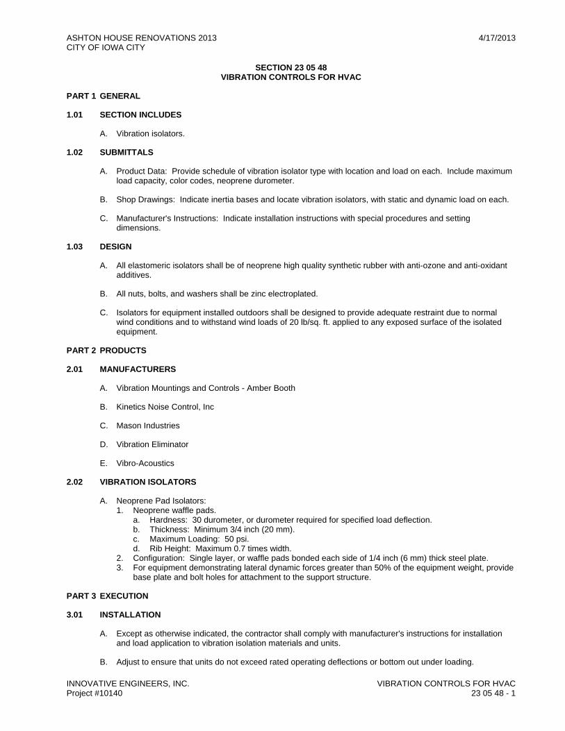
ASHTON HOUSE RENOVATIONS 2013 4/17/2013 CITY OF IOWA CITY
INNOVATIVE ENGINEERS, INC. VIBRATION CONTROLS FOR HVAC Project #10140 23 05 48 - 1
SECTION 23 05 48 VIBRATION CONTROLS FOR HVAC
PART 1 GENERAL
1.01 SECTION INCLUDES
A. Vibration isolators.
1.02 SUBMITTALS
A. Product Data: Provide schedule of vibration isolator type with location and load on each. Include maximum load capacity, color codes, neoprene durometer.
B. Shop Drawings: Indicate inertia bases and locate vibration isolators, with static and dynamic load on each.
C. Manufacturer's Instructions: Indicate installation instructions with special procedures and setting dimensions.
1.03 DESIGN
A. All elastomeric isolators shall be of neoprene high quality synthetic rubber with anti-ozone and anti-oxidant additives.
B. All nuts, bolts, and washers shall be zinc electroplated.
C. Isolators for equipment installed outdoors shall be designed to provide adequate restraint due to normal wind conditions and to withstand wind loads of 20 lb/sq. ft. applied to any exposed surface of the isolated equipment.
PART 2 PRODUCTS
2.01 MANUFACTURERS
A. Vibration Mountings and Controls - Amber Booth
B. Kinetics Noise Control, Inc
C. Mason Industries
D. Vibration Eliminator
E. Vibro-Acoustics
2.02 VIBRATION ISOLATORS
A. Neoprene Pad Isolators: 1. Neoprene waffle pads.
a. Hardness: 30 durometer, or durometer required for specified load deflection. b. Thickness: Minimum 3/4 inch (20 mm). c. Maximum Loading: 50 psi. d. Rib Height: Maximum 0.7 times width.
2. Configuration: Single layer, or waffle pads bonded each side of 1/4 inch (6 mm) thick steel plate. 3. For equipment demonstrating lateral dynamic forces greater than 50% of the equipment weight, provide
base plate and bolt holes for attachment to the support structure.
PART 3 EXECUTION
3.01 INSTALLATION
A. Except as otherwise indicated, the contractor shall comply with manufacturer's instructions for installation and load application to vibration isolation materials and units.
B. Adjust to ensure that units do not exceed rated operating deflections or bottom out under loading.
ASHTON HOUSE RENOVATIONS 2013 4/17/2013 CITY OF IOWA CITY
INNOVATIVE ENGINEERS, INC. VIBRATION CONTROLS FOR HVAC Project #10140 23 05 48 - 2
C. Remove space blocks and similar devices intended for temporary protection against overloading during installation.
D. Anchor and attach units to structural supports and equipment as required.
E. Adjust leveling devices as required where leveling uniformly onto isolators. Shim units as required where leveling devices cannot be used to distribute loading properly.
F. Where equipment base frames are specified, install base frames on isolator units so that a minimum of 1/2" clearance below the base will result when the supported equipment has been installed and loaded for operation. (2" clearance for inertia bases).
G. Contractor shall adjust all vibration isolators after the system has achieved full operating weight so that: no vibration isolation element is short circuited; no undue stress is applied to the equipment, connected piping or structure; and no noise is transmitted to any support structure, connected surface or adjacent environment.
H. After equipment installation and operation, it shall be the contractors' responsibility to demonstrate that the isolation system meets all of the criteria specified in this Section and on Drawings, and has been properly installed.
I. Prior to making piping connections to equipment with operating weights substantially different from installed weights, block up equipment with temporary shims to final height. When full load is applied, adjust isolators to load to allow shim removal.
J. Support piping connections to equipment mounted on isolators using isolators or resilient hangers for first three points of support.
3.02 SCHEDULE
A. Provide vibration isolators for AHU-1 and AHU-2.
END OF SECTION

ASHTON HOUSE RENOVATIONS 2013 4/17/2013 CITY OF IOWA CITY
INNOVATIVE ENGINEERS, INC. IDENTIFICATION FOR MECHANICAL SYSTEMS Project #10140 23 05 53 - 1
SECTION 23 05 53 IDENTIFICATION FOR MECHANICAL SYSTEMS
PART 1 GENERAL
1.01 SECTION INCLUDES
A. Nameplates.
B. Tags.
C. Pipe Markers.
1.02 REFERENCE STANDARDS
A. ASME A13.1 - Scheme for the Identification of Piping Systems; The American Society of Mechanical Engineers; 2007.
1.03 SUBMITTALS
A. List: Submit list of wording, symbols, letter size, and color coding for mechanical identification.
B. Chart and Schedule: Submit valve chart and schedule, including valve tag number, location, function, and valve manufacturer's name and model number.
C. Product Data: Provide manufacturers catalog literature for each product required.
PART 2 PRODUCTS
2.01 IDENTIFICATION APPLICATIONS
A. Air Handling Units: Nameplates.
B. Automatic Controls: Tags. Key to control schematic.
C. Dampers: Color coded tag.
D. Ductwork: Nameplates with gauge.
E. Instrumentation: Tags.
F. Major Components: Nameplates.
G. Piping: Tags printed with service and direction of flow.
H. Small-sized Equipment: Tags.
I. Thermostats: Nameplates.
2.02 MANUFACTURERS
A. Brady Corporation: www.bradycorp.com.
B. Champion America, Inc: www.Champion-America.com.
C. Seton Identification Products: www.seton.com/aec.
D. Brimar.
2.03 NAMEPLATES
A. Description: Laminated three-layer plastic with engraved letters. 1. Letter Color: White. 2. Letter Height: 1/4 inch.
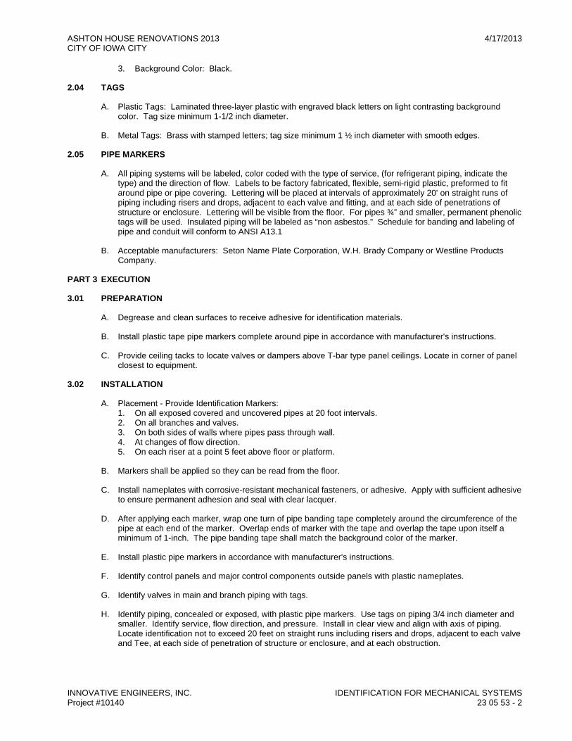
ASHTON HOUSE RENOVATIONS 2013 4/17/2013 CITY OF IOWA CITY
INNOVATIVE ENGINEERS, INC. IDENTIFICATION FOR MECHANICAL SYSTEMS Project #10140 23 05 53 - 2
3. Background Color: Black.
2.04 TAGS
A. Plastic Tags: Laminated three-layer plastic with engraved black letters on light contrasting background color. Tag size minimum 1-1/2 inch diameter.
B. Metal Tags: Brass with stamped letters; tag size minimum 1 ½ inch diameter with smooth edges.
2.05 PIPE MARKERS
A. All piping systems will be labeled, color coded with the type of service, (for refrigerant piping, indicate the type) and the direction of flow. Labels to be factory fabricated, flexible, semi-rigid plastic, preformed to fit around pipe or pipe covering. Lettering will be placed at intervals of approximately 20' on straight runs of piping including risers and drops, adjacent to each valve and fitting, and at each side of penetrations of structure or enclosure. Lettering will be visible from the floor. For pipes ¾” and smaller, permanent phenolic tags will be used. Insulated piping will be labeled as “non asbestos.” Schedule for banding and labeling of pipe and conduit will conform to ANSI A13.1
B. Acceptable manufacturers: Seton Name Plate Corporation, W.H. Brady Company or Westline Products Company.
PART 3 EXECUTION
3.01 PREPARATION
A. Degrease and clean surfaces to receive adhesive for identification materials.
B. Install plastic tape pipe markers complete around pipe in accordance with manufacturer's instructions.
C. Provide ceiling tacks to locate valves or dampers above T-bar type panel ceilings. Locate in corner of panel closest to equipment.
3.02 INSTALLATION
A. Placement - Provide Identification Markers: 1. On all exposed covered and uncovered pipes at 20 foot intervals. 2. On all branches and valves. 3. On both sides of walls where pipes pass through wall. 4. At changes of flow direction. 5. On each riser at a point 5 feet above floor or platform.
B. Markers shall be applied so they can be read from the floor.
C. Install nameplates with corrosive-resistant mechanical fasteners, or adhesive. Apply with sufficient adhesive to ensure permanent adhesion and seal with clear lacquer.
D. After applying each marker, wrap one turn of pipe banding tape completely around the circumference of the pipe at each end of the marker. Overlap ends of marker with the tape and overlap the tape upon itself a minimum of 1-inch. The pipe banding tape shall match the background color of the marker.
E. Install plastic pipe markers in accordance with manufacturer's instructions.
F. Identify control panels and major control components outside panels with plastic nameplates.
G. Identify valves in main and branch piping with tags.
H. Identify piping, concealed or exposed, with plastic pipe markers. Use tags on piping 3/4 inch diameter and smaller. Identify service, flow direction, and pressure. Install in clear view and align with axis of piping. Locate identification not to exceed 20 feet on straight runs including risers and drops, adjacent to each valve and Tee, at each side of penetration of structure or enclosure, and at each obstruction.

ASHTON HOUSE RENOVATIONS 2013 4/17/2013 CITY OF IOWA CITY
INNOVATIVE ENGINEERS, INC. IDENTIFICATION FOR MECHANICAL SYSTEMS Project #10140 23 05 53 - 3
I. Install ductwork with plastic nameplates. Identify with air handling unit identification number and area served. Locate identification at air handling unit, at each side of penetration of structure or enclosure, and at each obstruction.
J. Where a service is indicated on the drawings as a circulating system, the pipe marker legend for the particular service shall be followed by either the word “supply” or “return” to clarify the line function. An arrow designating direction of flow shall follow the legend on each marker.
K. Flow Indicators:
1. Provide an arrow marker at each identification marker, with arrow pointed away from legend in the direction of flow. When flow may be both ways, provide double-headed arrows.
L. Equipment Schedule: Tag and number each and every piece of equipment for every service included in this contract..
END OF SECTION
ASHTON HOUSE RENOVATIONS 2013 4/17/2013 CITY OF IOWA CITY
INNOVATIVE ENGINEERS, INC. IDENTIFICATION FOR MECHANICAL SYSTEMS Project #10140 23 05 53 - 4
THIS PAGE
INTENTIONALLY
LEFT BLANK

ASHTON HOUSE RENOVATIONS 2013 4/17/2013 CITY OF IOWA CITY
INNOVATIVE ENGINEERS, INC. TESTING ADJUSTING AND BALANCING FOR HVAC Project #10140 23 05 93 - 1
SECTION 23 05 93 TESTING ADJUSTING AND BALANCING FOR HVAC
PART 1 GENERAL
1.01 SECTION INCLUDES
A. Testing, adjustment, and balancing of air systems.
1.02 REFERENCE STANDARDS
A. ASHRAE Std 111 - Practices for Measurement, Testing, Adjusting and Balancing of Building Heating, Ventilation, Air-Conditioning, and Refrigeration Systems; American Society of Heating, Refrigerating and Air-Conditioning Engineers, Inc.; 1988, with 1997 Errata.
B. NEBB (TAB) - Procedural Standards for Testing Adjusting Balancing of Environmental Systems; National Environmental Balancing Bureau; 2005, Seventh Edition.
C. SMACNA (TAB) - HVAC Systems Testing, Adjusting, and Balancing; Sheet Metal and Air Conditioning Contractors' National Association; 2002.
D. AABC - Associated Air Balance Council; Test and Balance Procedure.
E. AABC - Associated Air Balance Council; National Standards for Total System Balance.
1.03 SUBMITTALS
A. TAB Plan: Submit a written plan indicating testing, adjusting, and balancing standard to be followed and specific approach for each system and component. 1. Detailed step-by-step Procedures for TAB work for each system and issue, including:
1) Terminal flow calibration (for each terminal type). 2) Diffuser proportioning. 3) Branch/submain proportioning. 4) Total flow calculations. 5) Rechecking. 6) Diversity issues. 7) Expected problems and solutions, etc. 8) Details of how TOTAL flow will be determined; for example:
a) Air: Sum of terminal flows via control system calibrated readings or via hood readings of all terminals, supply air (SA) and return air (RA) pitot traverse, SA or RA flow stations.
9) Specific procedures that will ensure that both air and water side are operating at lowest possible pressures and methods to verify this.
10) Methods for making coil or other system plant capacity measurements, if specified. 11) Exhaust fan balancing and capacity verifications, including any required room pressure
differentials. 12) Procedures for formal deficiency reports, including scope, frequency and distribution.
2. Sample report formats.
B. Final Report: Submit draft copies of report for review prior to final acceptance of Project. Provide final copies for Engineer and for inclusion in operating and maintenance manuals. 1. Preface: An explanation of intended use of control system. 2. Indicate deficiencies in systems that would prevent proper testing, adjusting, and balancing of systems
and equipment to achieve specified performance. 3. List of all air flow, system capacity and efficiency measurements to be performed and a description of
specific test procedures, parameters, formulas to be used. 4. Copy of field checkout sheets and logs to be used, listing each piece of equipment to be tested,
adjusted and balanced with data cells to be gathered for each. 5. Include actual instrument list, with manufacturer name, serial number, and date of calibration. 6. Identification and types of measurement instruments to be used and their most recent calibration date.
PART 2 PRODUCTS - NOT USED
ASHTON HOUSE RENOVATIONS 2013 4/17/2013 CITY OF IOWA CITY
INNOVATIVE ENGINEERS, INC. TESTING ADJUSTING AND BALANCING FOR HVAC Project #10140 23 05 93 - 2
PART 3 EXECUTION
3.01 GENERAL REQUIREMENTS
A. Perform total system balance in accordance with one of following: 1. AABC MN-1, AABC National Standards for Total System Balance. 2. ASHRAE Std 111, Practices for Measurement, Testing, Adjusting and Balancing of Building Heating,
Ventilation, Air-Conditioning, and Refrigeration Systems. 3. SMACNA HVAC Systems Testing, Adjusting, and Balancing. 4. Begin work after completion of systems to be tested, adjusted, or balanced and complete work prior to
Substantial Completion of project. 5. Where HVAC systems and/or components interface with life safety systems, including fire and smoke
detection, alarm, and control, coordinate scheduling and testing and inspection procedures with authorities having jurisdiction.
6. TAB Agency Qualifications: a. Company specializing in testing, adjusting, and balancing of systems specified in this section. b. Certified by one of following:
1) AABC, Associated Air Balance Council: www.aabchq.com; upon completion submit AABC National Performance Guaranty.
2) TABB, Testing, Adjusting, and Balancing Bureau of National Energy Management Institute: www.tabbcertified.org.
c. TAB Supervisor Qualifications: Professional Engineer licensed in Iowa.
3.02 EXAMINATION
A. Verify that systems are complete and operable before commencing work. Ensure following conditions: 1. Systems are started and operating in a safe and normal condition. 2. Temperature control systems are installed complete and operable. 3. Proper thermal overload protection is in place for electrical equipment. 4. Final filters are clean and in place. If required, install temporary media in addition to final filters. 5. Fans are rotating correctly. 6. Outdoor air dampers are in place and operating properly. 7. Air outlets are installed and connected. 8. Duct system leakage is minimized. 9. Submit field reports. Report defects and deficiencies that will or could prevent proper system balance. 10. Beginning of work means acceptance of existing conditions.
3.03 PREPARATION
A. Conduct pre-balancing meeting at least one week prior to starting TAB work. 1. Require attendance by all installers whose work will be tested, adjusted, or balanced. 2. Provide additional balancing devices, as required.
3.04 RECORDING AND ADJUSTING
A. Field Logs: Maintain written logs including: 1. Running log of events and issues. 2. Discrepancies, deficient or uncompleted work by others. 3. Contract interpretation requests. 4. Lists of completed tests. 5. Ensure recorded data represents actual measured or observed conditions. 6. Permanently mark settings of valves, dampers, and other adjustment devices allowing settings to be
restored. Set and lock memory stops. 7. After adjustment, take measurements to verify balance has not been disrupted or that such disruption
has been rectified. 8. Leave systems in proper working order, replacing belt guards, closing access doors, closing doors to
electrical switch boxes, and restoring thermostats to specified settings.
3.05 AIR SYSTEM PROCEDURE
A. Adjust air handling and distribution systems to provide required or design supply, return, and exhaust air quantities at site altitude.
ASHTON HOUSE RENOVATIONS 2013 4/17/2013 CITY OF IOWA CITY
INNOVATIVE ENGINEERS, INC. TESTING ADJUSTING AND BALANCING FOR HVAC Project #10140 23 05 93 - 3
B. Measure air quantities at air inlets and outlets.
C. Vary total system air quantities by adjustment of fan speeds. Provide drive changes required. Vary branch air quantities by damper regulation.
D. Provide system schematic with required and actual air quantities recorded at each outlet or inlet.
E. Measure static air pressure conditions on air supply units, including filter and coil pressure drops, and total pressure across fan.
3.06 SCOPE
A. Test, adjust, and balance following: 1. Air Handling Units 2. Air Dampers 3. Air Inlets and Outlets
3.07 MINIMUM DATA TO BE REPORTED
A. Electric Motors: 1. Manufacturer 2. HP/BHP 3. Phase, voltage, amperage; nameplate, actual, no load 4. RPM 5. V-Belt Drives:
a. Identification/location b. Required driven RPM c. Driven sheave, diameter and RPM d. Belt, size and quantity e. Motor sheave diameter and RPM
6. Cooling Coils: a. Identification/number b. Location c. Service d. Manufacturer e. Air flow, design and actual f. Entering air DB temperature, design and actual g. Leaving air DB temperature, design and actual h. Refrigerant flow, design and actual i. Refrigerant pressure drop, design and actual j. Entering refrigerant temperature, design and actual k. Leaving refrigerant temperature, design and actual l. Air pressure drop, design and actual
7. Furnace: a. Identification/number b. Location c. Service d. Manufacturer e. Air flow, design and actual f. Natural gas flow, design and actual g. Entering air temperature, design and actual h. Leaving air temperature, design and actual i. Air pressure drop, design and actual
8. Air Moving Equipment: a. Location b. Manufacturer c. Model number d. Serial number e. Arrangement/Class/Discharge f. Air flow, specified and actual g. Outside air flow, specified and actual h. Total static pressure (total external), specified and actual i. Inlet pressure

ASHTON HOUSE RENOVATIONS 2013 4/17/2013 CITY OF IOWA CITY
INNOVATIVE ENGINEERS, INC. TESTING ADJUSTING AND BALANCING FOR HVAC Project #10140 23 05 93 - 4
j. Discharge pressure k. Sheave Make/Size/Bore l. Number of Belts/Make/Size m. Fan RPM
9. Outside Air: a. Identification/location b. Design air flow c. Actual air flow d. Design outside air flow e. Actual outside air flow
10. Exhaust Fans: a. Location b. Manufacturer c. Model number d. Serial number e. Air flow, specified and actual f. Total static pressure (total external), specified and actual g. Sheave Make/Size/Bore h. Number of Belts/Make/Size i. Fan RPM
11. Air Monitoring Stations: a. Identification/location b. System c. Size d. Area e. Design velocity f. Design air flow g. Test velocity h. Test air flow
12. Existing Terminal Unit Data: a. Manufacturer b. Type, constant, variable, single, dual duct c. Identification/number d. Location e. Model number f. Size g. Minimum static pressure h. Minimum design air flow i. Maximum design air flow j. Maximum actual air flow k. Inlet static pressure l. Water flow, design and actual m. Entering water temperature, design and actual n. Leaving water temperature, design and actual
END OF SECTION
ASHTON HOUSE RENOVATIONS 2013 4/17/2013 CITY OF IOWA CITY
INNOVATIVE ENGINEERS, INC. DUCT INSULATION Project #10140 23 07 13 - 1
SECTION 23 07 13 DUCT INSULATION
PART 1 GENERAL
1.01 SECTION INCLUDES
A. Duct insulation.
1.02 REFERENCE STANDARDS
A. ASTM C 518 - Standard Test Method for Steady-State Thermal Transmission Properties by Means of the Heat Flow Meter Apparatus; 2004.
B. ASTM C 553 - Specification for Mineral Fiber Blanket Thermal Insulation for Commercial and Industrial Applications; 2002.
C. ASTM C 612 - Standard Specification for Mineral Fiber Block and Board Thermal Insulation; 2004.
D. ASTM E 84 - Standard Test Method for Surface Burning Characteristics of Building Materials; 2008.
E. ASTM E 96/E 96M - Standard Test Methods for Water Vapor Transmission of Materials; 2005.
F. SMACNA (DCS) - HVAC Duct Construction Standards - Metal and Flexible; Sheet Metal and Air Conditioning Contractors' National Association; 2005.
G. UL 723 - Standard for Test for Surface Burning Characteristics of Building Materials; Underwriters Laboratories Inc.; 2008.
1.03 SUBMITTALS
A. Product Data: Provide product description, thermal characteristics, list of materials and thickness for each service, and locations.
B. Shop Drawings: 1. Indicate complete material data, mastics and adhesives. 2. Materials proposed for this project thickness of material for individual services.
C. Certification: 1. Certifications or other data to show compliance with these specifications and governing regulations. 2. Proof of compliance for test of products for fire rating, corrosiveness and compressive strength.
PART 2 PRODUCTS
2.01 REQUIREMENTS FOR ALL PRODUCTS OF THIS SECTION
A. Surface Burning Characteristics: Flame spread/Smoke developed index of 25/50, maximum, when tested in accordance with ASTM E 84, NFPA 255, or UL 723.
2.02 GLASS FIBER, FLEXIBLE - Type DC-1
A. Manufacturer: 1. Knauf Insulation: www.knaufusa.com. 2. Johns Manville Corporation: www.jm.com. 3. Owens Corning Corp: www.owenscorning.com. 4. CertainTeed Corporation: www.certainteed.com.
B. Insulation: ASTM C 553; flexible, noncombustible blanket. 1. 'K' value: 0.36 at 75°F, when tested in accordance with ASTM C 518. 2. Maximum Service Temperature: 450°F. 3. Maximum Water Vapor Sorption: 5.0 percent by weight. 4. Accessories:
a. Jacket: Factory applied foil-reinforced-kraft vapor barrier type. b. Fire Hazard Classification: 25 flame spread; 50 smoke developed.

ASHTON HOUSE RENOVATIONS 2013 4/17/2013 CITY OF IOWA CITY
INNOVATIVE ENGINEERS, INC. DUCT INSULATION Project #10140 23 07 13 - 2
c. Provide staples, bands, wires, tape, anchors, corner angles and similar accessories recommended by insulation manufacturer for applications indicated.
d. Provide cements, waterproof adhesives, coatings, sealers, protective finishes and similar compounds recommended by insulation manufacturer for applications indicated.
2.03 GLASS FIBER, RIGID - Type DC-2
A. Manufacturer: 1. Knauf Insulation: www.knaufusa.com. 2. Johns Manville Corporation: www.jm.com. 3. Owens Corning Corp: www.owenscorning.com. 4. CertainTeed Corporation: www.certainteed.com.
B. Insulation: ASTM C 612; rigid, noncombustible blanket. 1. 'K' value: 0.24 at 75 degrees F, when tested in accordance with ASTM C 518. 2. Maximum service temperature: 450°F. 3. Maximum Water Vapor Sorption: 5.0 percent. 4. Maximum Density: 8.0 lb/cu ft.
C. Accessories:
1. Jacket: Factory applied foil-reinforced-kraft vapor barrier type.
2. Fire Hazard Classification: 25 flame spread; 50 smoke developed.
3. Provide staples, bands, wires, tape, anchors, corner angles and similar accessories recommended by insulation manufacturer for applications indicated.
4. Provide cements, waterproof adhesives, coatings, sealers, protective finishes and similar compounds recommended by insulation manufacturer for applications indicated.
D. Install work at ambient and equipment temperatures recommended by adhesive manufacturer.
PART 3 EXECUTION
3.01 EXAMINATION
A. Verify that ducts have been tested before applying insulation materials.
B. Verify that surfaces are clean, foreign material removed, and dry.
3.02 INSTALLATION
A. Install in accordance with manufacturer's instructions.
B. Install in accordance with NAIMA National Insulation Standards.
C. Insulated ducts conveying air below ambient temperature: 1. Provide insulation with vapor barrier jackets. 2. Finish with tape and vapor barrier jacket. 3. Continue insulation through walls, sleeves, hangers, and other duct penetrations. 4. Insulate entire system including fittings, joints, flanges, fire dampers, flexible connections, and
expansion joints.
3.03 TYPE DC-1 and DC-2 INSULATION INSTALLATION
A. Insulation: Continuous through inside non-fire rated walls; see details on drawings for fire, smoke and smoke-fire damper installation in fire rated walls; or for undampered penetrations of fire rated walls.
B. Finish neatly at hangers, supports and other protrusions.

ASHTON HOUSE RENOVATIONS 2013 4/17/2013 CITY OF IOWA CITY
INNOVATIVE ENGINEERS, INC. DUCT INSULATION Project #10140 23 07 13 - 3
C. Wrap insulation tight on duct, ensure corners are not compressed, with all circumferential joints butted. Provide a 2” facing overlap at all joints. Staple longitudinal joints with outward clinching staples, 6” on center; tape all joints with a vapor-barrier tape compatible with insulation facing. 1. Duct surfaces over 24” wide, insulation shall utilize mechanical fasteners spaced not more than 18” on
center, not more than 3” from an edge. 2. Seal all punctures, staples, penetrations with vapor-barrier tape. 3. Apply to top exterior surface of diffusers, including neck if exposed. Seal all seams, joints and ends
with vapor-barrier tape.
3.04 SCHEDULES
A. Exhaust Ducts within 10 ft of Exterior Openings: Type DC-2 1. Rigid Glass Fiber Duct Insulation: 2 inches thick.
B. Exhaust Ducts Exposed to Outdoor Air: 1. No insulation.
C. Supply Ducts (Cooling and Heating): 1. Supply and Return Ducts Exposed in Mechanical Rooms - Type DC-2
a. Rigid Glass Fiber Duct Insulation: 2 inches thick. 2. Supply Ducts and Return in Vertical Shafts: Type DC-1
a. Flexible Glass Fiber Duct Insulation: 1-1/2 inches thick. 3. Supply and Return Ducts in concealed ceilings in finished spaces: Type DC-1
a. Flexible Glass Fiber Duct Insulation: 1-1/2 inches thick.
END OF SECTION

ASHTON HOUSE RENOVATIONS 2013 4/17/2013 CITY OF IOWA CITY
INNOVATIVE ENGINEERS, INC. DUCT INSULATION Project #10140 23 07 13 - 4
THIS PAGE
INTENTIONALLY
LEFT BLANK
ASHTON HOUSE RENOVATIONS 2013 4/17/2013 CITY OF IOWA CITY
INNOVATIVE ENGINEERS, INC. PIPE INSULATION Project #10140 23 07 19 - 1
SECTION 23 07 19 PIPE INSULATION
PART 1 GENERAL
1.01 SECTION INCLUDES
A. Piping insulation.
B. Jackets and accessories.
1.02 REFERENCE STANDARDS
A. ASTM A 666 - Standard Specification for Annealed or Cold-Worked Austenitic Stainless Steel Sheet, Strip, Plate, and Flat Bar; 2003.
B. ASTM C 177 - Standard Test Method for Steady-State Heat Flux Measurements and Thermal Transmission Properties by Means of the Guarded Hot Plate Apparatus; 2004.
C. ASTM C 534/C 534M - Standard Specification for Preformed Flexible Elastomeric Cellular Thermal Insulation in Sheet and Tubular Form; 2008.
D. ASTM C 547 - Standard Specification for Mineral Fiber Pipe Insulation; 2007.
E. ASTM C 795 - Standard Specification for Thermal Insulation for Use in Contact with Austenitic Stainless Steel; 2008.
F. ASTM E 84 - Standard Test Method for Surface Burning Characteristics of Building Materials; 2008.
G. ASTM E 96/E 96M - Standard Test Methods for Water Vapor Transmission of Materials; 2005.
H. NFPA 255 - Standard Method of Test of Surface Burning Characteristics of Building Materials; National Fire Protection Association; 2006.
I. UL 723 - Standard for Test for Surface Burning Characteristics of Building Materials; Underwriters Laboratories Inc.; 2008.
1.03 SUBMITTALS
A. Product Data: Provide product description, thermal characteristics, list of materials and thickness for each service, and locations.
1.04 QUALITY ASSURANCE
A. Manufacturer Qualifications: Company specializing in manufacturing the Products specified in this section with not less than three years of documented experience.
B. Applicator Qualifications: Company specializing in performing the type of work specified in this section with minimum 3 years of experience.
1.05 DELIVERY, STORAGE, AND HANDLING
A. Accept materials on site, labeled with manufacturer's identification, product density, and thickness.
1.06 FIELD CONDITIONS
A. Maintain ambient conditions required by manufacturers of each product.
B. Maintain temperature before, during, and after installation for minimum of 24 hours.

ASHTON HOUSE RENOVATIONS 2013 4/17/2013 CITY OF IOWA CITY
INNOVATIVE ENGINEERS, INC. PIPE INSULATION Project #10140 23 07 19 - 2
PART 2 PRODUCTS
2.01 REQUIREMENTS FOR ALL PRODUCTS OF THIS SECTION
A. Surface Burning Characteristics: Flame spread/Smoke developed index of 25/50, maximum, when tested in accordance with ASTM E 84, NFPA 255, or UL 723.
2.02 GLASS FIBER
A. Manufacturers: 1. Knauf Insulation: www.knaufusa.com. 2. Johns Manville Corporation: www.jm.com. 3. Owens Corning Corp: www.owenscorning.com. 4. CertainTeed Corporation: www.certainteed.com.
B. Insulation: ASTM C 547 and ASTM C 795; rigid molded, noncombustible. 1. 'K' value: ASTM C 177, 0.22 at 75°F. 2. Maximum service temperature: 850°F. 3. Maximum moisture absorption: 0.2 percent by volume.
C. Vapor Barrier Jacket: White kraft paper with glass fiber yarn, bonded to aluminized film; moisture vapor transmission when tested in accordance with ASTM E 96/E 96M of 0.02 perm-inches.
2.03 FLEXIBLE ELASTOMERIC CELLULAR INSULATION
A. Manufacturer: 1. AP-Armacell International: www.armacell.com. 2. Rubatex International: www.rubatex.com.
B. Insulation: Preformed flexible elastomeric cellular rubber insulation complying with ASTM C 534 Grade 1; use molded tubular material wherever possible. 1. Minimum Service Temperature: -40°F. 2. Maximum Service Temperature: 220°F. 3. Connection: Waterproof vapor barrier adhesive. 4. Elastomeric Foam Adhesive: Air dried, contact adhesive, compatible with insulation.
2.04 JACKETS
A. PVC Plastic. 1. Jacket: One piece molded type fitting covers and sheet material.
a. Minimum Service Temperature: 0°F. b. Maximum Service Temperature: 150°F. c. Moisture Vapor Permeability: 0.002 perm inch, maximum, when tested in accordance with ASTM E
96/E 96M. d. Thickness: 10 mil. e. Connections: Brush on welding adhesive.
PART 3 EXECUTION
3.01 EXAMINATION
A. Verify that piping has been tested before applying insulation materials. Notice shall be sent to the engineer before installation with a copy of the system's test report before insulating lines
B. Verify that surfaces are clean and dry, with foreign material removed.
3.02 PREPARATION:
A. Before covering, test and approve piping.
B. Entire surface: Clean and dry at time of installation. 1. Insulation: dry before and during application. 2. Finish with systems at operating conditions.
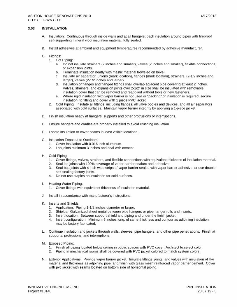
ASHTON HOUSE RENOVATIONS 2013 4/17/2013 CITY OF IOWA CITY
INNOVATIVE ENGINEERS, INC. PIPE INSULATION Project #10140 23 07 19 - 3
3.03 INSTALLATION
A. Insulation: Continuous through inside walls and at all hangers; pack insulation around pipes with fireproof self-supporting mineral wool insulation material, fully sealed.
B. Install adhesives at ambient and equipment temperatures recommended by adhesive manufacturer.
C. Fittings: 1. Hot Piping:
a. Do not insulate strainers (2 inches and smaller), valves (2 inches and smaller), flexible connections, or expansion joints.
b. Terminate insulation neatly with mastic material troweled on bevel. c. Insulate air separator, unions (mark location), flanges (mark location), strainers, (2-1/2 inches and
larger), valves (2-1/2 inches and larger). d. Insulation of flanges and flanged fittings shall overlap adjacent pipe covering at least 2 inches.
Valves, strainers, and expansion joints over 2-1/2" in size shall be insulated with removable insulation cover that can be removed and reapplied without tools or new fasteners.
e. Where rigid insulation with vapor barrier is not used or "packing" of insulation is required, secure insulation to fitting and cover with 1 piece PVC jacket
2. Cold Piping: Insulate all fittings, including flanges, all valve bodies and devices, and all air separators associated with cold surfaces. Maintain vapor barrier integrity by applying a 1-piece jacket.
D. Finish insulation neatly at hangers, supports and other protrusions or interruptions.
E. Ensure hangers and cradles are properly installed to avoid crushing insulation.
F. Locate insulation or cover seams in least visible locations.
G. Insulation Exposed to Outdoors: 1. Cover insulation with 0.016 inch aluminum. 2. Lap joints minimum 3 inches and seal with cement.
H. Cold Piping: 1. Cover fittings, valves, strainers, and flexible connections with equivalent thickness of insulation material. 2. Seal lap joints with 100% coverage of vapor barrier sealant and adhesive. 3. Seal butt joints with 4 inch wide strips of vapor barrier sealed with vapor barrier adhesive; or use double
self-sealing factory joints. 4. Do not use staples on insulation for cold surfaces.
I. Heating Water Piping: 1. Cover fittings with equivalent thickness of insulation material.
J. Install in accordance with manufacturer's instructions.
K. Inserts and Shields: 1. Application: Piping 1-1/2 inches diameter or larger. 2. Shields: Galvanized sheet metal between pipe hangers or pipe hanger rolls and inserts. 3. Insert location: Between support shield and piping and under the finish jacket. 4. Insert configuration: Minimum 6 inches long, of same thickness and contour as adjoining insulation;
may be factory fabricated.
L. Continue insulation and jackets through walls, sleeves, pipe hangers, and other pipe penetrations. Finish at supports, protrusions, and interruptions.
M. Exposed Piping: 1. Finish all piping located below ceiling in public spaces with PVC cover. Architect to select color. 2. Piping in mechanical rooms shall be covered with PVC jacket colored to match system colors
N. Exterior Applications: Provide vapor barrier jacket. Insulate fittings, joints, and valves with insulation of like material and thickness as adjoining pipe, and finish with glass mesh reinforced vapor barrier cement. Cover with pvc jacket with seams located on bottom side of horizontal piping.
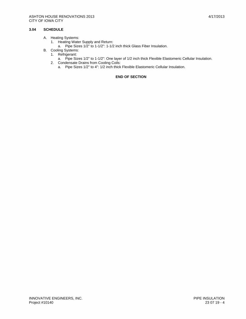
ASHTON HOUSE RENOVATIONS 2013 4/17/2013 CITY OF IOWA CITY
INNOVATIVE ENGINEERS, INC. PIPE INSULATION Project #10140 23 07 19 - 4
3.04 SCHEDULE
A. Heating Systems: 1. Heating Water Supply and Return:
a. Pipe Sizes 1/2" to 1-1/2": 1-1/2 inch thick Glass Fiber Insulation. B. Cooling Systems:
1. Refrigerant: a. Pipe Sizes 1/2" to 1-1/2": One layer of 1/2 inch thick Flexible Elastomeric Cellular Insulation.
2. Condensate Drains from Cooling Coils: a. Pipe Sizes 1/2" to 4": 1/2 inch thick Flexible Elastomeric Cellular Insulation.
END OF SECTION
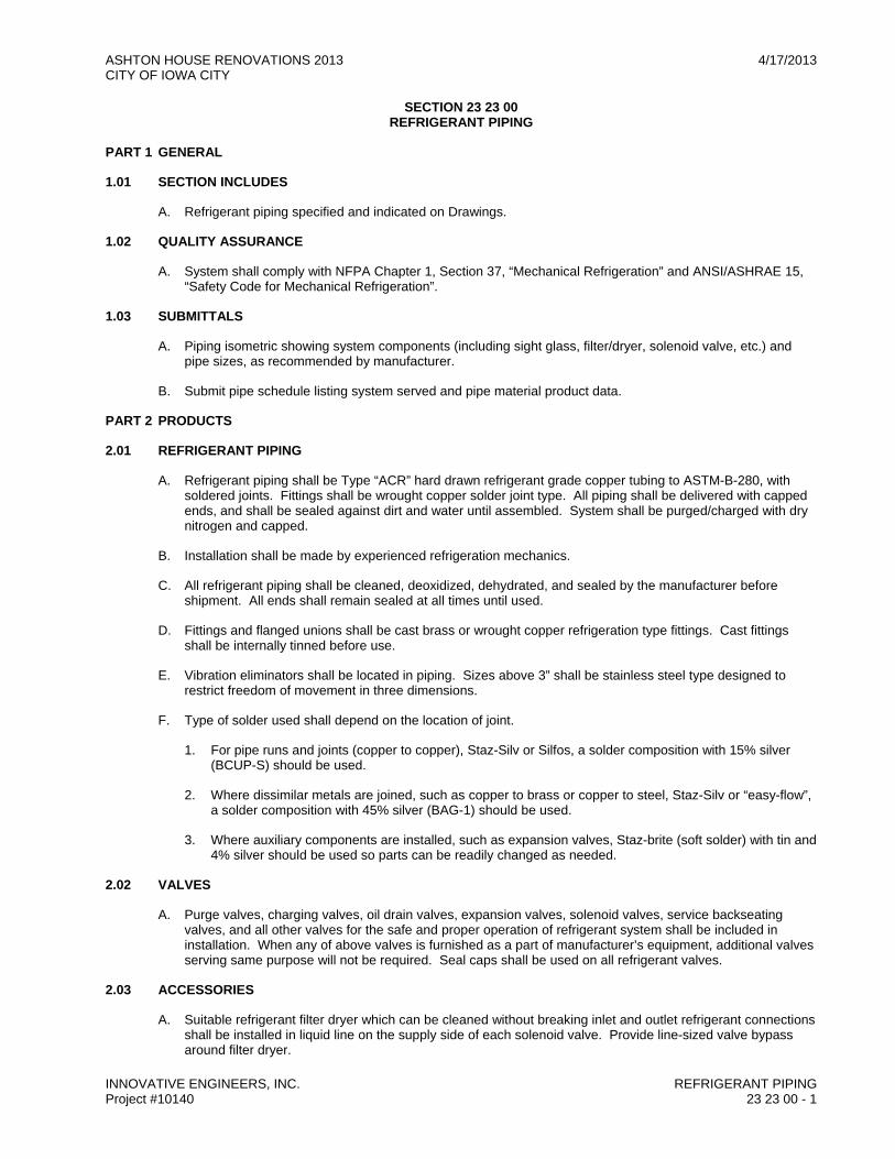
ASHTON HOUSE RENOVATIONS 2013 4/17/2013 CITY OF IOWA CITY
INNOVATIVE ENGINEERS, INC. REFRIGERANT PIPING Project #10140 23 23 00 - 1
SECTION 23 23 00 REFRIGERANT PIPING
PART 1 GENERAL
1.01 SECTION INCLUDES
A. Refrigerant piping specified and indicated on Drawings.
1.02 QUALITY ASSURANCE
A. System shall comply with NFPA Chapter 1, Section 37, “Mechanical Refrigeration” and ANSI/ASHRAE 15, “Safety Code for Mechanical Refrigeration”.
1.03 SUBMITTALS
A. Piping isometric showing system components (including sight glass, filter/dryer, solenoid valve, etc.) and pipe sizes, as recommended by manufacturer.
B. Submit pipe schedule listing system served and pipe material product data.
PART 2 PRODUCTS
2.01 REFRIGERANT PIPING
A. Refrigerant piping shall be Type “ACR” hard drawn refrigerant grade copper tubing to ASTM-B-280, with soldered joints. Fittings shall be wrought copper solder joint type. All piping shall be delivered with capped ends, and shall be sealed against dirt and water until assembled. System shall be purged/charged with dry nitrogen and capped.
B. Installation shall be made by experienced refrigeration mechanics.
C. All refrigerant piping shall be cleaned, deoxidized, dehydrated, and sealed by the manufacturer before shipment. All ends shall remain sealed at all times until used.
D. Fittings and flanged unions shall be cast brass or wrought copper refrigeration type fittings. Cast fittings shall be internally tinned before use.
E. Vibration eliminators shall be located in piping. Sizes above 3” shall be stainless steel type designed to restrict freedom of movement in three dimensions.
F. Type of solder used shall depend on the location of joint.
1. For pipe runs and joints (copper to copper), Staz-Silv or Silfos, a solder composition with 15% silver (BCUP-S) should be used.
2. Where dissimilar metals are joined, such as copper to brass or copper to steel, Staz-Silv or “easy-flow”, a solder composition with 45% silver (BAG-1) should be used.
3. Where auxiliary components are installed, such as expansion valves, Staz-brite (soft solder) with tin and 4% silver should be used so parts can be readily changed as needed.
2.02 VALVES
A. Purge valves, charging valves, oil drain valves, expansion valves, solenoid valves, service backseating valves, and all other valves for the safe and proper operation of refrigerant system shall be included in installation. When any of above valves is furnished as a part of manufacturer’s equipment, additional valves serving same purpose will not be required. Seal caps shall be used on all refrigerant valves.
2.03 ACCESSORIES
A. Suitable refrigerant filter dryer which can be cleaned without breaking inlet and outlet refrigerant connections shall be installed in liquid line on the supply side of each solenoid valve. Provide line-sized valve bypass around filter dryer.

ASHTON HOUSE RENOVATIONS 2013 4/17/2013 CITY OF IOWA CITY
INNOVATIVE ENGINEERS, INC. REFRIGERANT PIPING Project #10140 23 23 00 - 2
B. Receivers shall be of steel construction, ASME rated and shall carry ASME stamp. Receiver shall be completely insulated with a removable cover over the ASME label. Receivers shall be fitted with armored sight glasses with ball check gauge valves. Receivers shall be fitted with drain valves accessibly located and fitted with hose coupling threads.
C. Acceptable manufacturers: Refrigeration Research, Sporlan, or Superior.
PART 3 EXECUTION
3.01 INSTALLATION OF PIPING
A. Refrigerant piping shall be installed as indicated on the drawings, and all equipment and piping shall be maintained absolutely dry and clean during handling and assembly. All flux and solder and scale shall be thoroughly cleaned from tube, and tubes shall be used during start up and shall be removed upon completion of testing. System will be inspected by the Design Professional before it is released for unattended operation.
B. Piping shall be carefully jointed using a nitrogen bleed during soldering. Piping shall have oil trap and suction line shall pitch down in direction of flow.
C. Refrigeration piping shall be tested for leaks and evacuated as follows: 1. Build up 20 psig in system with mixture of 90% nitrogen and 10% freon and then increase pressure to
150 psig in suction piping and 350 psig in high side piping with dry nitrogen. Leak test with halide torch or leak detector. Repair all leaks. Repeat procedure until system is proven tight.
2. Bleed off pressure into portable storage containers (not to atmosphere) and install vacuum pump capable of evacuating to 0.1” HG absolute. Temperature shall be above 60°F during evacuation. Evacuate the system to 0.1” HG absolute with ZIMMERLI vacuum gauge or manometer. If the system does not hold vacuum for a period of two hours, go to step two.
3. Charge system with proper quantity of refrigerant. 4. After 80 hours of operation place new elements in filter driers. 5. Venting of refrigerant to atmosphere is prohibited. Reclaim all refrigerant whenever system is to be
evacuated.
D. Refrigerant and Oil:
1. Contractor shall furnish sufficient refrigerant to charge each system. Amount of installed charges shall be permanently stamped on the receiver or compressor. Systems shall be fully charged at time of acceptance. In addition, Contractor shall furnish whatever additional amount of refrigerant may be required during guaranteed period due to repairs, replacements, or adjustments that Contractor may be required to make under guarantee provisions.
2. Same requirement shall apply to compressor lubricating oil except that amount charged or added shall be stamped on system.
END OF SECTION

ASHTON HOUSE RENOVATIONS 2013 4/17/2013 CITY OF IOWA CITY
INNOVATIVE ENGINEERS, INC. HVAC DUCTS AND CASINGS Project #10140 23 31 00 - 1
SECTION 23 31 00 HVAC DUCTS AND CASINGS
PART 1 GENERAL
1.01 SECTION INCLUDES
A. Metal ductwork.
B. Nonmetal ductwork.
C. Miscellaneous Blankoff Panels
1.02 REFERENCE STANDARDS
A. ASHRAE Handbooks - Fundamentals, Applications, Systems, latest editions.
B. ASTM A 653/A 653M - Standard Specification for Steel Sheet, Zinc-Coated (Galvanized) or Zinc-Iron Alloy-Coated (Galvannealed) by Hot-Dip Process; 2007.
C. NFPA 90A - Standard for Installation of Air-Conditioning and Ventilating Systems; National Fire Protection Association; 2009.
D. SMACNA (LEAK) - HVAC Air Duct Leakage Test Manual; Sheet Metal and Air Conditioning Contractors' National Association; 1985, First Edition.
E. SMACNA (DCS) - HVAC Duct Construction Standards - Metal and Flexible; Sheet Metal and Air Conditioning Contractors' National Association; 2005.
F. SMACNA - HVAC Systems - Duct Design.
1.03 PERFORMANCE REQUIREMENTS
A. Ducts shall have minimum internal dimensions indicated on drawings. Whenever necessary to change shape of duct, it shall be done gradually and full area retained in accordance with ASHRAE “Table of Equivalence Rectangular and Round Ducts.”
B. Ductwork, unless otherwise shown on drawings, or specified herein, shall be G-90 galvanized steel sheets (F.S. QQ-S-775, Type 1, Class E) and joints shall be constructed so as not to trap condensed water.
C. Minimum construction standards for sound plenums, supply air plenums, return air plenums, outside air plenums, mixed air plenums shall be SMACNA design for four (4) inches water gauge. All remaining ductwork shall be per Schedule in 3.04B.
D. Contractor may furnish equivalent round duct in lieu of rectangular ductwork shown on drawings; round pipe and fittings shall be as specified, maintaining friction rate equal to design. Design ceiling heights, soffits, lighting layouts, piping layouts, etc. shall not be revised to facilitate round duct option unless approved by Architect. Contractor remains responsible for coordination with and/or revisions to work of other trades.
E. Where it is necessary that any portion of duct system be built around pipes, conduits, beams, or other obstructions, provide air stream deflectors for smooth flow at Contractor's cost. Maintain air stream velocity at obstruction; if required, enlarge duct to maintain this velocity at Contractor's cost.
F. Mitered elbows shall be furnished with turning vanes, unless noted otherwise, consisting of single thickness vanes, constructed to prevent vibration and eliminate air noise. 1. Elbows with unequal dimensions in plane of turn shall have leading and trailing edges of vanes parallel
to sides of duct. 2. Use radius throat elbows where shown or noted on drawings; Contractor may elect to use radius throat
elbows in lieu of square elbows with turning vanes as shown. Where indicated on drawings large radius throat elbows shall be provided with radius air turn vanes.
1.04 SUBMITTALS
A. Product Data: Provide data for duct materials.
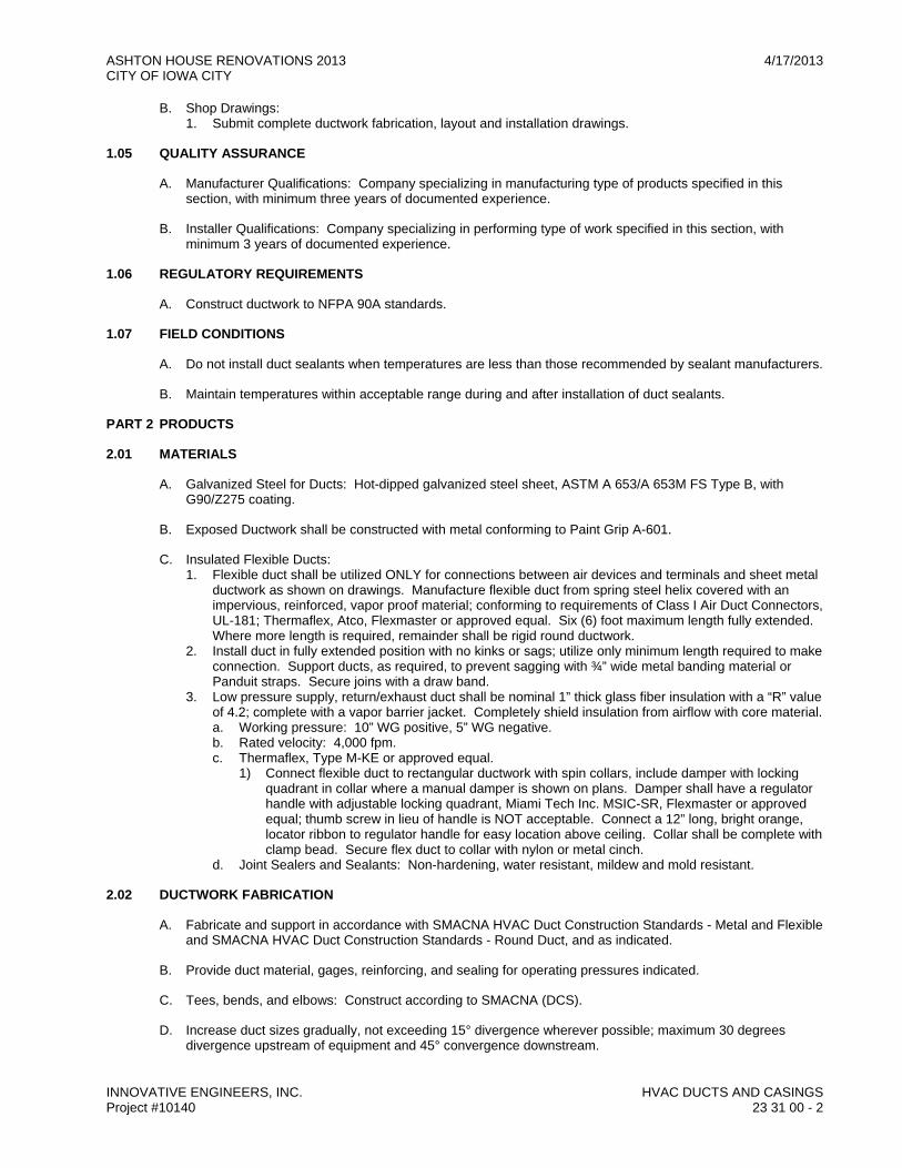
ASHTON HOUSE RENOVATIONS 2013 4/17/2013 CITY OF IOWA CITY
INNOVATIVE ENGINEERS, INC. HVAC DUCTS AND CASINGS Project #10140 23 31 00 - 2
B. Shop Drawings: 1. Submit complete ductwork fabrication, layout and installation drawings.
1.05 QUALITY ASSURANCE
A. Manufacturer Qualifications: Company specializing in manufacturing type of products specified in this section, with minimum three years of documented experience.
B. Installer Qualifications: Company specializing in performing type of work specified in this section, with minimum 3 years of documented experience.
1.06 REGULATORY REQUIREMENTS
A. Construct ductwork to NFPA 90A standards.
1.07 FIELD CONDITIONS
A. Do not install duct sealants when temperatures are less than those recommended by sealant manufacturers.
B. Maintain temperatures within acceptable range during and after installation of duct sealants.
PART 2 PRODUCTS
2.01 MATERIALS
A. Galvanized Steel for Ducts: Hot-dipped galvanized steel sheet, ASTM A 653/A 653M FS Type B, with G90/Z275 coating.
B. Exposed Ductwork shall be constructed with metal conforming to Paint Grip A-601.
C. Insulated Flexible Ducts: 1. Flexible duct shall be utilized ONLY for connections between air devices and terminals and sheet metal
ductwork as shown on drawings. Manufacture flexible duct from spring steel helix covered with an impervious, reinforced, vapor proof material; conforming to requirements of Class I Air Duct Connectors, UL-181; Thermaflex, Atco, Flexmaster or approved equal. Six (6) foot maximum length fully extended. Where more length is required, remainder shall be rigid round ductwork.
2. Install duct in fully extended position with no kinks or sags; utilize only minimum length required to make connection. Support ducts, as required, to prevent sagging with ¾” wide metal banding material or Panduit straps. Secure joins with a draw band.
3. Low pressure supply, return/exhaust duct shall be nominal 1” thick glass fiber insulation with a “R” value of 4.2; complete with a vapor barrier jacket. Completely shield insulation from airflow with core material. a. Working pressure: 10” WG positive, 5” WG negative. b. Rated velocity: 4,000 fpm. c. Thermaflex, Type M-KE or approved equal.
1) Connect flexible duct to rectangular ductwork with spin collars, include damper with locking quadrant in collar where a manual damper is shown on plans. Damper shall have a regulator handle with adjustable locking quadrant, Miami Tech Inc. MSIC-SR, Flexmaster or approved equal; thumb screw in lieu of handle is NOT acceptable. Connect a 12” long, bright orange, locator ribbon to regulator handle for easy location above ceiling. Collar shall be complete with clamp bead. Secure flex duct to collar with nylon or metal cinch.
d. Joint Sealers and Sealants: Non-hardening, water resistant, mildew and mold resistant.
2.02 DUCTWORK FABRICATION
A. Fabricate and support in accordance with SMACNA HVAC Duct Construction Standards - Metal and Flexible and SMACNA HVAC Duct Construction Standards - Round Duct, and as indicated.
B. Provide duct material, gages, reinforcing, and sealing for operating pressures indicated.
C. Tees, bends, and elbows: Construct according to SMACNA (DCS).
D. Increase duct sizes gradually, not exceeding 15° divergence wherever possible; maximum 30 degrees divergence upstream of equipment and 45° convergence downstream.
ASHTON HOUSE RENOVATIONS 2013 4/17/2013 CITY OF IOWA CITY
INNOVATIVE ENGINEERS, INC. HVAC DUCTS AND CASINGS Project #10140 23 31 00 - 3
E. Fabricate continuously welded round fittings in accordance with SMACNA HVAC Duct Construction Standards - Metal and Flexible.
F. Provide standard 45° lateral wye takeoffs unless otherwise indicated where 90° conical tee connections may be used.
G. Where exhaust and relief air ductwork is connected to exterior wall louvers and duct outlet is smaller than louver frame, provide insulated metal blank-out panels sealing louver area around duct. Use same material as duct, painted black on exterior side; seal to louver frame and duct. Transition intake ductwork to full louver area.
H. Duct connectors as manufactured by Ductmate Industries may be used at Contractors option, but must meet all SMACNA requirements, including leakage class as specified.
2.03 ROUND DUCTWORK
A. Ductwork and fittings shall be factory manufactured or machine fabricated of galvanized steel with lock formed joints and seams. 1. Pressure classes up to 2” static pressure round ductwork shall be spiral seam pipe (spiral, grooved)
with all joints and seams sealed with Hardcast Foil Grip, or equal; brush on sealant of any kid is NOT considered an equal. Include damper with locking quadrant in collar where a manual damper is shown on plans.
2. Connect to rectangular ductwork with spin collars or job fabricated transitions; seal airtight with Hardcast Foil Grip or equal; brush on sealant of any kind is NOT considered an equal. Where drawings indicate 45 degree entry taps or 45 degree lateral fittings, conical lateral or like fittings shall be used.
3. Fittings shall be wall thickness not less than that specified for ductwork; mitered, pleated and adjustable elbows are not acceptable. Where drawings indicate 45 degree entry taps or lateral fittings, conical lateral or like fittings shall be used.
4. Snaplock ductwork is NOT acceptable. a. Pressure classes above 2” static pressure round ductwork and fittings of rigid spiral seam
construction as manufactured by SEMCO or United McGill. Submit manufacturer's data for approval.
b. Construct fittings of spiral seam bodies and continuously welded longitudinal seam bodies and arms. Use “one piece” die formed elbow in sizes 3 thru 8 inch. Smoothly draw branch entry on divided flow fittings before welding branch.
c. Seal joints with Hardcast Aluma Grip AFT-701 or equal; brush on sealant of any kind is NOT considered an equal.
PART 3 EXECUTION
3.01 INSTALLATION
A. Install, support, and seal ducts in accordance with SMACNA HVAC Duct Construction Standards - Metal and Flexible. SMACNA seal class “A” for all operating pressures. Locate ducts with sufficient space around equipment to allow normal operating and maintenance activities. 1. Duct sizes indicated are inside clear dimensions. 2. Install and seal metal and flexible ducts in accordance with SMACNA HVAC Duct Construction
Standards - Metal and Flexible. 3. Provide openings in ductwork where required to accommodate thermometers and controllers. Provide
pilot tube openings where required for testing of systems, complete with metal can with spring device or screw to ensure against air leakage. Where openings are provided in insulated ductwork, install insulation material inside a metal ring.
4. Use crimp joints with or without bead for joining round duct sizes 8 inch and smaller with crimp in direction of air flow.
5. All ductwork seams shall be sealed with hard cast joint sealant compound or heat shrink plastic per SMACNA high pressure standards.
6. Ducts shall be of internal dimensions shown on drawings. In no case shall be indicated size of ductwork be changed without prior approval of Architect/Engineer. Wherever it is necessary to change shape of duct, it shall be done gradually and full area retained.
7. Ducts shall be constructed with easy elbow fittings except where square turns are specifically indicated on drawings or are approved by Architect/Engineer. throat radius elbows shall be 12 inches minimum except where space is not available in which case radius shall be as large as possible, but not less than a radius ratio of 1.5. Turning vanes must be used in miter elbows.
ASHTON HOUSE RENOVATIONS 2013 4/17/2013 CITY OF IOWA CITY
INNOVATIVE ENGINEERS, INC. HVAC DUCTS AND CASINGS Project #10140 23 31 00 - 4
8. Ducts shall be stiffened as necessary to prevent sagging or buckling and to provide a rigid installation and freedom from vibration and noise when fan is operating.
9. Means for expansion of long lengths of duct should be provided. 10. Use double nuts and lock washers on threaded rod supports. 11. As an option contractor can substitute double wall for rectangular ductwork in exposed areas.
a. Ductwork delivered to jobsite shall be covered watertight, and not placed directly on ground or floor without being elevated by blocking to prevent water intrusion. No ductwork shall be installed without first having interior wiped clean and dry.
b. NO DUCTWORK SHALL BE INSTALLED WITH DAMP INSULATION OR DUST/DIRT IN INTERIOR. Any ductwork found in this condition shall be removed from site immediately and replaced, all at contractor's expense.
12. During construction provide temporary closures of metal or taped polyethylene on open ductwork to prevent construction dust from entering ductwork system. NO DUCTWORK SHALL BE LEFT OPEN AT END OF A WORKDAY. Any ductwork found open at start of a workday shall be cleaned immediately or replaced, at contractor's expense.
3.02 HANGERS AND SUPPORTS FOR DUCTS
A. Horizontal ducts shall be supported with substantial angle and rod or strap iron trapeze hangers not less than 1/8 inch by 1 inch placed entirely around sides and bottoms of ducts and securely fastened to ducts and to construction above.
B. Attachments to steel beams shall be by “C” clamps. Rods shall be not less than 5/16 inch diameter with eye close to ceiling and matching bolt to attach trapeze duct hanger. Use double nuts and lock washers on threaded rod supports.
C. Horizontal duct supports shall be spaced not to exceed 8 feet apart and at least two trapeze supports per section of duct (this maximum spacing applies to both round and rectangular ducts).
D. Ducts 24 inches or greater in width, height or diameter shall be stiffened with galvanized structural angle reinforcing (round ducts shall be reinforced with prefabricated rings), not to exceed four feet on centers and on all four surfaces (entire circumference on round ducts), to prevent sagging or buckling and to provide a rigid installation and freedom from vibration and noise. Where angle cleats are made of same gauge metal as ducts (or heavier) angle cleats shall serve as reinforcing members on two surfaces of ducts at joints in ducts. Additional reinforcing angles shall be provided adjacent to branch duct connections, which are of less width or depth than surface of main duct at points of connection and at all other locations to make ductwork free from noise and vibration when fans are operating.
3.03 CLEANING PROCEDURE AFTER INSTALLATION
A. Initial Cleaning: Clean duct system and force air at high velocity through duct to remove accumulated dust. To obtain sufficient air, clean half system at a time. Protect equipment that could be harmed by excessive dirt with temporary filters, or bypass during cleaning.
B. Intermediate Cleaning: Clean duct systems with high power HEPA vacuum machines. Protect equipment that could be harmed by excessive dirt with filters, or bypass during cleaning. Provide adequate access into ductwork for cleaning purposes.
C. Final Cleaning: All ductwork and equipment that is accessible through access panels shall be hand wiped with oil-free tack rags.
3.04 SCHEDULES
A. Ductwork Material: 1. All Supply: Steel. 2. Return and Relief: Steel. 3. Outside Air Intake: Steel. 4. Ductwork Pressure Class:
a. Supply (Downstream of Air Terminal Unit): 2 inch. b. Supply (From Air Handling Unit to Air Terminal Unit): 4 inch. c. Return and Relief: 3 inch. d. Outside Air Intake: 3 inch.

ASHTON HOUSE RENOVATIONS 2013 4/17/2013 CITY OF IOWA CITY
INNOVATIVE ENGINEERS, INC. HVAC DUCTS AND CASINGS Project #10140 23 31 00 - 5
3.05 LEAKAGE TESTING OF INSTALLED SYSTEM
A. Contractor shall perform a leak test all duct fabricated. Testing of duct system in sections is permissible provided that all sections are tested.
B. Conduct tests, in presence of Engineer, at static pressures equal to maximum design pressure of system or section being tested. Do not pressurize systems above maximum design operating pressure. Give seven (7) days advanced notice for testing.
C. Maximum Allowable Leakage: As described in SMACNA “HVAC Air Duct Leakage Test Manual.” Comply with requirements for SMACNA Leakage Classification 3 for all pressure classes.
D. Leakage test procedures shall follow outlines and classifications in SMACNA “HVAC Duct Leakage Test Manual.”
E. If specimen fails to meet allotted leakage level, contractor shall modify to bring it into compliance and shall retest it until acceptable leakage is demonstrated.
F. Tests and necessary repair shall be completed prior to insulation and/or concealment of ducts.
END OF SECTION

ASHTON HOUSE RENOVATIONS 2013 4/17/2013 CITY OF IOWA CITY
INNOVATIVE ENGINEERS, INC. HVAC DUCTS AND CASINGS Project #10140 23 31 00 - 6
THIS PAGE
INTENTIONALLY
LEFT BLANK
ASHTON HOUSE RENOVATIONS 2013 4/17/2013 CITY OF IOWA CITY
INNOVATIVE ENGINEERS, INC. AIR DUCT ACCESSORIES Project #10140 23 33 00 - 1
SECTION 23 33 00 AIR DUCT ACCESSORIES
PART 1 GENERAL
1.01 SECTION INCLUDES
A. Duct Access Doors.
B. Duct Test Holes.
C. Flexible Duct Connections.
D. Volume Control Dampers.
1.02 REFERENCE STANDARDS
A. NFPA 90A - Standard for the Installation of Air-Conditioning and Ventilating Systems; National Fire Protection Association; 2009.
B. NFPA 92A - Standard for Smoke-Control Systems Utilizing Barriers and Pressure Differences; 2009.
C. SMACNA (DCS) - HVAC Duct Construction Standards - Metal and Flexible; Sheet Metal and Air Conditioning Contractors' National Association; 2005.
D. UL 33 - Heat Responsive Links for Fire-Protection Service; Underwriters Laboratories Inc.; 2003.
E. UL 555 - Standard for Fire Dampers; Underwriters Laboratories Inc.; 2006.
F. UL 555S - Standard for Leakage Rated Dampers for Use in Smoke Control Systems; Underwriters Laboratories Inc.; 1999.
1.03 SUBMITTALS
A. Product Data: Provide for shop fabricated assemblies. Include electrical characteristics and connection requirements.
B. Shop Drawings: Indicate for shop fabricated assemblies including volume control dampers.
1.04 QUALITY ASSURANCE
A. Manufacturer Qualifications: Company specializing in manufacturing the type of products specified in this section, with minimum three years of documented experience.
B. Products Requiring Electrical Connection: Listed and classified by Underwriters Laboratories Inc. as suitable for the purpose specified and indicated.
1.05 DELIVERY, STORAGE, AND HANDLING
A. Protect dampers from damage to operating linkages and blades.
B. Cover all temporary ductwork locations outdoors and indoors with tape and polyethylene covers to prevent dust and dirt from entering the ductwork at all times.
PART 2 PRODUCTS
2.01 DUCT ACCESS DOORS
A. Manufacturers: 1. Greenheck Fan Corp: www.greenheck.com 2. Nailor Industries Inc: www.nailor.com. 3. Ruskin Company: www.ruskin.com. 4. SEMCO Incorporated: www.semcoinc.com. 5. United Enertech

ASHTON HOUSE RENOVATIONS 2013 4/17/2013 CITY OF IOWA CITY
INNOVATIVE ENGINEERS, INC. AIR DUCT ACCESSORIES Project #10140 23 33 00 - 2
B. Fabrication: Rigid and close-fitting of galvanized steel with sealing gaskets and quick fastening locking devices. For insulated ducts, install minimum 1 inch thick insulation with sheet metal cover. 1. Up to 18 inches Square: Provide two hinges and two sash locks. 2. Up to 24 x 48 inches: Three hinges and two compression latches with outside and inside handles. 3. Larger Sizes: Provide an additional hinge.
C. Access doors with sheet metal screw fasteners are not acceptable.
2.02 DUCT TEST HOLES
A. Temporary Test Holes: Cut or drill in ducts as required. Cap with neat patches, neoprene plugs, threaded plugs, or threaded or twist-on metal caps.
B. Permanent Test Holes: Factory fabricated, air tight flanged fittings with screw cap. Provide extended neck fittings to clear insulation.
2.03 FLEXIBLE DUCT CONNECTIONS
A. Fabricate in accordance with SMACNA HVAC Duct Construction Standards - Metal and Flexible, and as indicated.
B. Flexible Duct Connections: Fabric crimped into metal edging strip. 1. Fabric: UL listed fire-retardant neoprene coated woven glass fiber fabric to NFPA 90A, minimum
density 30 oz per sq yd. 2. Net Fabric Width: Approximately 2 inches wide. 3. Metal: 3 inches wide, 24 gage thick galvanized steel. 4. Temperature: 10°F to 275°F. 5. Pressure: (+) (-) 10” w.g.
C. Flexible duct connections for stainless steel lab exhaust or similar systems shall be stainless steel flanged with a two-layer Teflon coated fiberglass construction. Connectors shall comply with UL Standards #214 and NFPA 102.
D. Connections shall be factory fabricated 1-unit molded body and flanges with adequate joint flexibility to allow for thermal, axial, transverse and torsional movement. Connections shall also be capable of absorbing vibrations of connected equipment. Equip with corrosion-resistant steel flanges and retaining rings with a fabric reinforced elastomer.
E. Where duct connections are made to fans, air handlers, rooftop units, etc. or where ducts of dissimilar metal are connected, a noncombustible flexible connection having a nonfibrous surface exposed to the air stream (i.e. rubber or neoprene coated fabric) or other noncombustible materials approximately 6 inches in width, conforming to ASTM Specification D 1571-67 shall be installed.
F. Interior connections shall be fire retardant, 30 ounce closely woven glass fabric, double coated with neoprene. Ventfabrics, Inc. Ventglas Metaledge; Duro Dyne Corp.; or approved equal.
G. Exterior connections exposed to weather shall be fire retardant, 26 ounce closely woven glass fabric, double coated with Hypalon, resistant to sunlight, ozone and weather. Ventfabrics, Inc. Ventlon; duro Dyne Corp.; or approved equal.
2.04 VOLUME CONTROL DAMPERS
A. Manufacturers: 1. Ruskin Company: www.ruskin.com (MD35, MD25, MDRS25) 2. Louvers & Dampers, Inc: www.louvers-dampers.com 3. Nailor Industries Inc: www.nailor.com 4. Greenheck Fan Corp: www.greenheck.com 5. Pottorff 6. United Enertech
B. Fabricate in accordance with SMACNA HVAC Duct Construction Standards - Metal and Flexible, and as indicated. Fabricate of galvanized steel, minimum 16 ga thickness (equal to above).

ASHTON HOUSE RENOVATIONS 2013 4/17/2013 CITY OF IOWA CITY
INNOVATIVE ENGINEERS, INC. AIR DUCT ACCESSORIES Project #10140 23 33 00 - 3
C. Splitter Dampers: 1. Material: Same gage as duct to 24 inches size in either direction, and two gages heavier for sizes over
24 inches.
D. Single Blade Dampers: Fabricate for duct sizes up to 6 x 24 inch.
E. Multi-Blade Damper: Fabricate of opposed blade pattern with maximum blade sizes 8 x 72 inch. Assemble center and edge crimped blades in prime coated or galvanized channel frame with suitable hardware.
PART 3 EXECUTION
3.01 INSTALLATION
A. Install accessories in accordance with manufacturer's instructions, NFPA 90A, and follow SMACNA HVAC Duct Construction Standards - Metal and Flexible and SMACNA HVAC Duct Construction Standards - Round Ducts. Refer to Section 23 31 00 for duct construction and pressure class.
1. Provide backdraft dampers on exhaust fans or exhaust ducts nearest to outside, relief air louver and where indicated.
2. Provide duct access doors for inspection and cleaning before and after filters, coils, fans, automatic dampers, at fire dampers, combination fire and smoke dampers, and elsewhere as indicated. Provide minimum 18 x 18 inch size and as indicated. Provide 4 x 4 inch for balancing dampers only. Review locations prior to fabrication.
3. Provide duct test holes where indicated and required for testing and balancing purposes.
4. For fans developing static pressures of 5.0 inches and over, cover flexible connections with leaded vinyl sheet, held in place with metal straps.
5. Use splitter dampers only where indicated.
6. Provide balancing dampers on duct take-off to diffusers, grilles, and registers, regardless of whether dampers are specified as part of the diffuser, grille, or register assembly. Install minimum 2 duct widths from duct take-off.
END OF SECTION

ASHTON HOUSE RENOVATIONS 2013 4/17/2013 CITY OF IOWA CITY
INNOVATIVE ENGINEERS, INC. AIR DUCT ACCESSORIES Project #10140 23 33 00 - 4
THIS PAGE
INTENTIONALLY
LEFT BLANK

ASHTON HOUSE RENOVATIONS 2013 4/17/2013 CITY OF IOWA CITY
INNOVATIVE ENGINEERS, INC. AIR OUTLETS AND INLETS Project #10140 23 37 00 - 1
SECTION 23 37 00 AIR OUTLETS AND INLETS
PART 1 GENERAL
1.01 SECTION INCLUDES
A. Diffusers.
B. Registers/grilles.
C. Relief hoods.
1.02 REFERENCE STANDARDS
A. AMCA 500-L - Laboratory Methods of Testing Louvers for Rating; Air Movement and Control Association International, Inc.; 2007.
B. ASHRAE Std 70 - Method of Testing for Rating Performance of Air Outlets and Inlets; American Society of Heating, Refrigerating and Air Conditioning Engineers, Inc.; 2006.
C. SMACNA (DCS) - HVAC Duct Construction Standards - Metal and Flexible; Sheet Metal and Air Conditioning Contractors' National Association; 2005.
1.03 SUBMITTALS
A. Product Data: Provide data for equipment required for this project. Review outlets and inlets as to size, finish, and type of mounting prior to submission. Submit schedule of outlets and inlets showing type, size, location, application, and noise level.
B. Architect shall review all diffuser and grille submittal.
C. All diffusers and grilles final finishes and colors to be selected by architect from standard finish chart. Submit finish and color chart with submittals.
1.04 QUALITY ASSURANCE
A. Test and rate air outlet and inlet performance in accordance with ASHRAE Std 70.
B. Manufacturer Qualifications: Company specializing in manufacturing type of products specified in this section, with minimum three years of documented experience.
PART 2 PRODUCTS
2.01 MANUFACTURERS
A. Titus: www.titus-hvac.com.
B. Carnes Company HVAC: www.carnes.com.
C. Krueger: www.krueger-hvac.com.
D. Price Industries: www.price-hvac.com.
E. Metal*aire www.metalaire.com
F. Nailor
G. Tuttle and Bailey.
2.02 RECTANGULAR CEILING DIFFUSERS
A. Basis of design, Titus OMNI.

ASHTON HOUSE RENOVATIONS 2013 4/17/2013 CITY OF IOWA CITY
INNOVATIVE ENGINEERS, INC. AIR OUTLETS AND INLETS Project #10140 23 37 00 - 2
B. Fabrication: Aluminum with factory off-white enamel finish.
C. Type: Square, panel ceiling diffuser to discharge air in 360 degree pattern with sectorizing baffles where indicated.
D. Frame: Hard ceiling type. In plaster ceilings, provide plaster frame and ceiling frame.
2.03 WALL EXHAUST AND RETURN REGISTERS/GRILLES
A. Basis of design, Titus 350 FL.
B. Type: Streamlined blades, 3/4 inch minimum depth, 3/4 inch maximum spacing, with spring or other device to set blades, horizontal face.
C. Frame: 1-1/4 inch margin with concealed mounting.
D. Fabrication: Steel with factory white finish.
E. Damper: Integral, gang-operated, opposed blade type with removable key operator, operable from face.
PART 3 EXECUTION
3.01 INSTALLATION
A. Install in accordance with manufacturer's instructions.
B. Check location of outlets and inlets and make necessary adjustments in position to conform with architectural features, symmetry, and lighting arrangement.
C. Install diffusers to ductwork with air tight connection.
D. Provide balancing dampers on duct take-off to diffusers, and grilles and registers, despite whether dampers are specified as part of diffuser, or grille and register assembly.
E. All screws and fastening hardware to be concealed where available. Fasteners exposed to chlorine environment, provide 316L stainless steel hardware.
3.02 SCHEDULES
A. See plan drawings for schedule.
B. Verify plan drawings for all duct connection sizes and ceiling types prior to final selection.
END OF SECTION
ASHTON HOUSE RENOVATIONS 2013 4/17/2013 CITY OF IOWA CITY
INNOVATIVE ENGINEERS, INC. HVAC AIR CLEANING DEVICES Project #10140 23 40 00 - 1
SECTION 23 40 00 HVAC AIR CLEANING DEVICES
PART 1 GENERAL
1.01 SECTION INCLUDES
A. Air filtration filters.
B. Filter frames.
C. Filter gages.
1.02 REFERENCE STANDARDS
A. ARI 850 - Commercial and Industrial Air Filter Equipment; Air-Conditioning and Refrigeration Institute; 2004.
B. ASHRAE Std 52.2 - Method of Testing General Ventilation Air-Cleaning Devices for Removal Efficiency by Particle Size; American Society of Heating, Refrigerating and Air-Conditioning Engineers, Inc.; 2007.
C. UL 900 - Standard for Air Filter Units; Underwriters Laboratories Inc.; 2004.
1.03 PERFORMANCE REQUIREMENTS
A. Conform to ARI 850 Section 7.4. 1. Dust Spot Efficiency: Plus or minus 5 percent.
1.04 SUBMITTALS
A. Product Data: Provide data on filter media, filter performance data, filter assembly and filter frames, dimensions, motor locations and electrical characteristics and connection requirements.
B. Shop Drawings: Indicate filter assembly and filter frames, dimensions, motor locations, and electrical characteristics and connection requirements.
C. Manufacturer's Installation Instructions: Indicate assembly and change-out procedures.
D. Operation and Maintenance Data: Include instructions for operation, changing, and periodic cleaning.
E. Maintenance Materials: Furnish the following for University of Missouri's use in maintenance of project. 1. Extra Filters: Provide new clean filters at substantial completion when building is turned over to Owner.
1.05 QUALITY ASSURANCE
A. Products Requiring Electrical Connection: Listed and classified by Underwriters Laboratories Inc. as suitable for the purpose specified and indicated.
1.06 EXTRA MATERIALS
A. Provide specified filters for temporary use during construction, and replace with new filters when the differential pressure is at 70 percent of dirty filter reading.
B. Replace filters at start of Commissioning and again at final acceptance by Owner.
C. Furnish one (1) extra set of new filters for each filter bank after Substantial Completion, including but not limited to the following: 1. Replaceable throwaway. 2. Replaceable dry type medium and high efficiency. 3. High efficiency caissons.
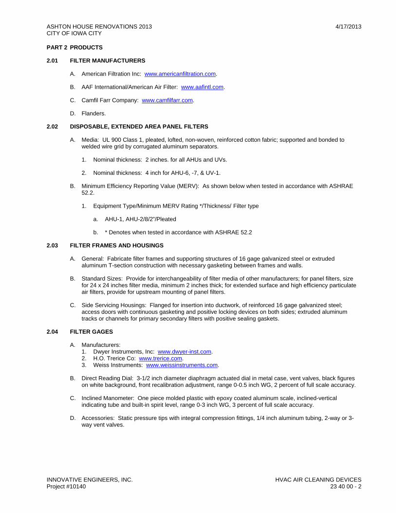
ASHTON HOUSE RENOVATIONS 2013 4/17/2013 CITY OF IOWA CITY
INNOVATIVE ENGINEERS, INC. HVAC AIR CLEANING DEVICES Project #10140 23 40 00 - 2
PART 2 PRODUCTS
2.01 FILTER MANUFACTURERS
A. American Filtration Inc: www.americanfiltration.com.
B. AAF International/American Air Filter: www.aafintl.com.
C. Camfil Farr Company: www.camfilfarr.com.
D. Flanders.
2.02 DISPOSABLE, EXTENDED AREA PANEL FILTERS
A. Media: UL 900 Class 1, pleated, lofted, non-woven, reinforced cotton fabric; supported and bonded to welded wire grid by corrugated aluminum separators.
1. Nominal thickness: 2 inches. for all AHUs and UVs.
2. Nominal thickness: 4 inch for AHU-6, -7, & UV-1.
B. Minimum Efficiency Reporting Value (MERV): As shown below when tested in accordance with ASHRAE 52.2.
1. Equipment Type/Minimum MERV Rating */Thickness/ Filter type
a. AHU-1, AHU-2/8/2”/Pleated
b. * Denotes when tested in accordance with ASHRAE 52.2
2.03 FILTER FRAMES AND HOUSINGS
A. General: Fabricate filter frames and supporting structures of 16 gage galvanized steel or extruded aluminum T-section construction with necessary gasketing between frames and walls.
B. Standard Sizes: Provide for interchangeability of filter media of other manufacturers; for panel filters, size for 24 x 24 inches filter media, minimum 2 inches thick; for extended surface and high efficiency particulate air filters, provide for upstream mounting of panel filters.
C. Side Servicing Housings: Flanged for insertion into ductwork, of reinforced 16 gage galvanized steel; access doors with continuous gasketing and positive locking devices on both sides; extruded aluminum tracks or channels for primary secondary filters with positive sealing gaskets.
2.04 FILTER GAGES
A. Manufacturers: 1. Dwyer Instruments, Inc: www.dwyer-inst.com. 2. H.O. Trerice Co: www.trerice.com. 3. Weiss Instruments: www.weissinstruments.com.
B. Direct Reading Dial: 3-1/2 inch diameter diaphragm actuated dial in metal case, vent valves, black figures on white background, front recalibration adjustment, range 0-0.5 inch WG, 2 percent of full scale accuracy.
C. Inclined Manometer: One piece molded plastic with epoxy coated aluminum scale, inclined-vertical indicating tube and built-in spirit level, range 0-3 inch WG, 3 percent of full scale accuracy.
D. Accessories: Static pressure tips with integral compression fittings, 1/4 inch aluminum tubing, 2-way or 3-way vent valves.

ASHTON HOUSE RENOVATIONS 2013 4/17/2013 CITY OF IOWA CITY
INNOVATIVE ENGINEERS, INC. HVAC AIR CLEANING DEVICES Project #10140 23 40 00 - 3
PART 3 EXECUTION
3.01 INSTALLATION
A. Install air cleaning devices in accordance with manufacturer's instructions.
B. Prevent passage of unfiltered air around filters with felt, rubber, or neoprene gaskets.
C. Install filter gage static pressure tips upstream and downstream of filters. Mount filter gages on outside of filter housing or filter plenum, in accessible position. Adjust and level.
D. Do not operate fan system until filters (temporary or permanent) are in place. Replace temporary filters used during construction and testing, with clean set.
E. Provide filter gages on filter banks, installed with separate static pressure tips upstream and downstream of filters.
END OF SECTION

ASHTON HOUSE RENOVATIONS 2013 4/17/2013 CITY OF IOWA CITY
INNOVATIVE ENGINEERS, INC. HVAC AIR CLEANING DEVICES Project #10140 23 40 00 - 4
THIS PAGE
INTENTIONALLY
LEFT BLANK

ASHTON HOUSE RENOVATIONS 2013 4/17/2013 CITY OF IOWA CITY
INNOVATIVE ENGINEERS, INC. AIR COOLED REFRIGERANT CONDENSERS Project #10140 23 63 13 - 1
SECTION 23 63 13 AIR COOLED REFRIGERANT CONDENSERS
PART 1 GENERAL
1.01 SECTION INCLUDES
A. Refrigerant condenser package.
B. Charge of refrigerant and oil.
C. Electrical power connections.
1.02 REFERENCE STANDARDS
A. ARI 210/240 - Standard for Performance Rating of Unitary Air Conditioning and Air-Source Heat Pump Equipment; Air-Conditioning, Heating, and Refrigeration Institute; 2006.
B. ASHRAE Std 15 - Safety Standard for Refrigeration Systems; American Society of Heating, Refrigerating and Air-Conditioning Engineers, Inc.; 2007.
C. ASHRAE Std 20 - Methods of Testing for Rating Remote Mechanical-Draft Air Cooled Refrigerant Condensers; American Society of Heating, Refrigerating and Air-Conditioning Engineers, Inc.; 1997 (R2006).
D. ASHRAE Std 90.1 - Energy Efficient Design of New Buildings Except Low-Rise Residential Buildings; American Society of Heating, Refrigerating and Air Conditioning Engineers, Inc.; 2004.
E. NEMA 250 - Enclosures for Electrical Equipment (1000 Volts Maximum); National Electrical Manufacturers Association; 2003.
F. UL 207 - Refrigerant-Containing Components and Accessories, Nonelectrical; Underwriters Laboratories Inc.; 2001.
1.03 SUBMITTALS
A. Product Data: Provide rated capacities, weights, accessories, electrical requirements, and wiring diagrams.
B. Shop Drawings: Indicate components, assembly, dimensions, weights and loading, required clearances, and location and size of field connections. Include schematic layouts showing condenser, refrigeration compressors, cooling coils, refrigerant piping and accessories required for complete system.
C. Manufacturer's Instructions: Submit manufacturer's complete installation instructions.
1.04 DELIVERY, STORAGE, AND HANDLING
A. Comply with manufacturer's installation instruction for rigging, unloading and transporting units.
B. Protect units on site from physical damage. Protect coils.
PART 2 PRODUCTS
2.01 MANUFACTURERS
A. Carrier 24ABB: www.carrier.com.
B. Approved equivalent.
2.02 MANUFACTURED UNITS
A. Provide packaged, factory assembled, pre-wired unit, suitable for outdoor use consisting of casing, condensing coil and fans, integral sub-cooling coil liquid accumulator.

ASHTON HOUSE RENOVATIONS 2013 4/17/2013 CITY OF IOWA CITY
INNOVATIVE ENGINEERS, INC. AIR COOLED REFRIGERANT CONDENSERS Project #10140 23 63 13 - 2
B. Capacity: As Scheduled on drawings.
C. Construction and Ratings: In accordance with ARI 210/240 and UL 207. Testing shall be in accordance with ASHRAE Std 20.
D. House components in welded steel frame with steel panels with weather resistant, baked enamel finish. Unit casing shall be steel, reinforced and braced with a steel angle framework. Casing and accessories shall be chemically cleaned, phosphatized and coated with a baked enamel primer finish before assemble. Finish coat of air dry enamel shall be applied to all exterior surfaces after final assembly.
E. Coils shall be aluminum fins mechanically bonded to seamless copper tubing. Provide sub-cooling circuits. Air test under water to 425 psig (2900 kPa), and vacuum dehydrate. Seal with holding charge of nitrogen. All coils shall have an integral subcooling circuit for a minimum of 15°F subcooling and external liquid receiver.
F. Coil Guard: Expanded metal with lint screens.
G. Fans shall be vertical discharge direct driven propeller type condenser fans with fan guard on discharge, equipped with roller or ball bearings with grease fittings extended to outside of casing. All fans shall be statically and dynamically balanced and factory tested with the fan installed in the casing.
H. Weatherproof motors suitable for outdoor use, SINGLE PHASE, with permanent lubricated ball bearings and built-in current and thermal overload protection.
I. Controls shall be factory wired and mounted control panel, NEMA 250, containing fan motor starters, fan cycling thermostats, compressor interlock, and control transformer.
J. Provide thermostat to cycle fan motors in response to outdoor ambient temperature.
PART 3 EXECUTION
3.01 INSTALLATION
A. Install with manufacturer’s instructions.
B. Provide for connection to electrical service.
C. Provide connection to refrigeration piping system. Comply with ASHRAE Std 15.
D. Install condensing units on concrete base with isolation pads or vibration isolators.
E. Anchor condensing units to concrete base according to manufacturer’s written instructions.
F. Charge the condensing units and condensers with refrigerant.
G. Install accessories and any other equipment furnished loose by the manufacturer, according to manufacturer written instructions and electrical requirements.
H. Install thermometers and gages as recommended by the manufacturer and/or as shown on drawings.
I. Purge system to the outside.
J. Provide cooling season start-up, winter season shut-down service, for first year of operation.
K. Shut-down system if initial start-up and testing takes place in winter and machines are to remain inoperative. Repeat start-up and testing operation at beginning of first cooling season.
3.02 STARTUP AND TESTING
A. Inspect, equipment installation, including field-assembled components, and piping and electrical connections.
B. After complete installation startup checks, according to manufacturers written instructions, do following to demonstrate equipment operation and performance as intended. 1. Check refrigerant charge is sufficient and equipment has been tested for refrigerant leak. 2. Check bearing lubrication and oil levels. 3. Verify proper motor rotation. 4. Verify purge system, if installed, is functional and relief piping is routed outdoor. 5. Prepare a written report outlining the results of tests and inspections, and submit.
END OF SECTION

ASHTON HOUSE RENOVATIONS 2013 4/17/2013 CITY OF IOWA CITY
INNOVATIVE ENGINEERS, INC. EVAPORATIVE COILS Project #10140 23 73 13 - 1
SECTION 23 73 13 EVAPORATIVE COILS
PART 1 GENERAL
1.01 SECTION INCLUDES
A. Evaporative coils.
1.02 REFERENCE STANDARDS
A. ARI 210/240 - Standard for Performance Rating of Unitary Air Conditioning and Air-Source Heat Pump Equipment; Air-Conditioning, Heating, and Refrigeration Institute; 2006.
B. ASHRAE Std 15 - Safety Standard for Refrigeration Systems; American Society of Heating, Refrigerating and Air-Conditioning Engineers, Inc.; 2007.
C. ASHRAE Std 90.1 - Energy Efficient Design of New Buildings Except Low-Rise Residential Buildings; American Society of Heating, Refrigerating and Air Conditioning Engineers, Inc.; 2004.
D. UL 207 - Refrigerant-Containing Components and Accessories, Nonelectrical; Underwriters Laboratories Inc.; 2001.
1.03 SUBMITTALS
A. Product Data.
1.04 DELIVERY, STORAGE, AND HANDLING
A. Protect coils on site from physical damage.
PART 2 PRODUCTS
2.01 MANUFACTURERS
A. Carrier: www.carrier.com
B. Approved equivalent.
2.02 EVAPORATIVE COIL
A. Provide coil modules for cooling coils in air handling unit associated with air cooled refrigerant unit. Enclose coil case so no tubes are exposed or visible.
B. Coil selection shall not exceed maximum face velocity allowed by coil manufacturer. Face velocity shall not allow for moisture carryover from cooling coil.
C. Coils shall be burst tested to 450 psig and proof tested to 300 psig air pressure under water.
D. Suction headers shall be constructed of copper tubing and shall penetrate unit casing to allow for sweat connections to refrigerant lines. Unit casing shall have suction and liquid line connections clearly labeled on exterior of unit.
E. Cooling coil sections shall include sloped, insulated, double-walled drain pan to extend under coil section. 1. Drain connections shall be provided on one side of each drain pan. 2. Drain pans shall slope to prevent standing water.
PART 3 EXECUTION
3.01 INSTALLATION
A. Install in accordance with manufacturer's instructions.
B. Provide connection to refrigeration piping system. Comply with ASHRAE Std 15.

ASHTON HOUSE RENOVATIONS 2013 4/17/2013 CITY OF IOWA CITY
INNOVATIVE ENGINEERS, INC. EVAPORATIVE COILS Project #10140 23 73 13 - 2
C. Purge system to outside.
D. Provide cooling season start-up, winter season shut-down service, for first year of operation.
END OF SECTION
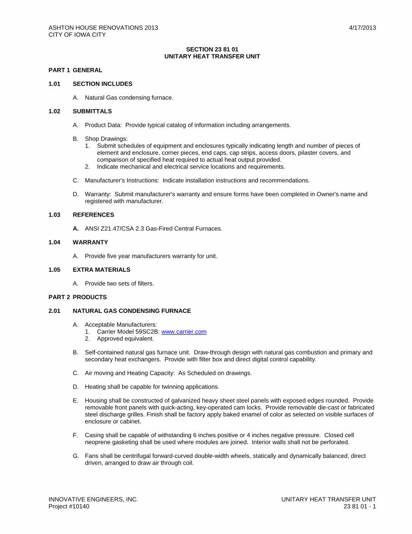
ASHTON HOUSE RENOVATIONS 2013 4/17/2013 CITY OF IOWA CITY
INNOVATIVE ENGINEERS, INC. UNITARY HEAT TRANSFER UNIT Project #10140 23 81 01 - 1
SECTION 23 81 01 UNITARY HEAT TRANSFER UNIT
PART 1 GENERAL
1.01 SECTION INCLUDES
A. Natural Gas condensing furnace.
1.02 SUBMITTALS
A. Product Data: Provide typical catalog of information including arrangements.
B. Shop Drawings: 1. Submit schedules of equipment and enclosures typically indicating length and number of pieces of
element and enclosure, corner pieces, end caps, cap strips, access doors, pilaster covers, and comparison of specified heat required to actual heat output provided.
2. Indicate mechanical and electrical service locations and requirements.
C. Manufacturer's Instructions: Indicate installation instructions and recommendations.
D. Warranty: Submit manufacturer's warranty and ensure forms have been completed in Owner's name and registered with manufacturer.
1.03 REFERENCES
A. ANSI Z21.47/CSA 2.3 Gas-Fired Central Furnaces.
1.04 WARRANTY
A. Provide five year manufacturers warranty for unit.
1.05 EXTRA MATERIALS
A. Provide two sets of filters.
PART 2 PRODUCTS
2.01 NATURAL GAS CONDENSING FURNACE
A. Acceptable Manufacturers: 1. Carrier Model 59SC2B: www.carrier.com 2. Approved equivalent.
B. Self-contained natural gas furnace unit. Draw-through design with natural gas combustion and primary and secondary heat exchangers. Provide with filter box and direct digital control capability.
C. Air moving and Heating Capacity: As Scheduled on drawings.
D. Heating shall be capable for twinning applications.
E. Housing shall be constructed of galvanized heavy sheet steel panels with exposed edges rounded. Provide removable front panels with quick-acting, key-operated cam locks. Provide removable die-cast or fabricated steel discharge grilles. Finish shall be factory apply baked enamel of color as selected on visible surfaces of enclosure or cabinet.
F. Casing shall be capable of withstanding 6 inches positive or 4 inches negative pressure. Closed cell neoprene gasketing shall be used where modules are joined. Interior walls shall not be perforated.
G. Fans shall be centrifugal forward-curved double-width wheels, statically and dynamically balanced, direct driven, arranged to draw air through coil.

ASHTON HOUSE RENOVATIONS 2013 4/17/2013 CITY OF IOWA CITY
INNOVATIVE ENGINEERS, INC. UNITARY HEAT TRANSFER UNIT Project #10140 23 81 01 - 2
H. Motor shall be tap wound multiple speed permanent split capacitor with sleeve bearings, resiliently mounted. Motor nameplate horsepower shall exceed brake horsepower by a minimum of 20 percent with forward curved fans. Motor shall be especially designed for quiet operation.
I. Control: Micro-processor based integrated electronic controls, factory wired, controllable by digital thermostat controller.
J. Filter: Easily removed 1 inch thick glass fiber throw-away type, located to filter air before coil.
K. Isolators shall be provided with internal leveling bolts, adjustable neoprene stabilizers, locating pin in center of top casting, 1/4-inch thick neoprene jacketed precompressed molded fiberglass noise isolation pad bonded to the underside of the unit, and 1/4-inch thick precompressed molded fiberglass noise isolation pad bonded to the top of the isolator. Vibration isolators shall be adjusted for maximum efficiency.
PART 3 EXECUTION
3.01 INSTALLATION
A. Install in accordance with manufacturer's instructions.
B. Install equipment exposed to finished areas after walls and ceiling are finished. Do not damage equipment or finishes.
C. Protection: Provide finished cabinet units with protective covers during balance of construction.
D. Locate as indicated on drawings, level and shim units, and anchor to structure. .
E. Connect thermostat and controls to units.
3.02 CLEANING
A. After construction is completed, including painting, clean exposed surfaces of units. Vacuum clean coils and inside of cabinets.
B. Touch-up marred or scratched surfaces of factory-finished cabinets, using finish materials furnished by manufacturer.
C. Install new filters. END OF SECTION

ASHTON HOUSE RENOVATIONS 2013 4/17/2013 CITY OF IOWA CITY
INNOVATIVE ENGINEERS, INC. COMMON WORK RESULTS FOR ELECTRICAL Project #10140 260500 - 1
SECTION 26 05 00 COMMON WORK RESULTS FOR ELECTRICAL
PART 1 - GENERAL
1.01 WORK INCLUDES
A. All labor, materials, equipment, tools and services required to perform all work and services for execution, installation and completion of all electrical work including all parts lists, operating instructions, wiring and control diagrams as shown on the drawings and as specified and completely coordinated with work of all other trades.
B. All supplementary or miscellaneous items, appurtenances and devices incidental to or necessary for a sound, secure and complete electrical installation, although such work is not specifically indicated.
C. Complete, in operative condition and to approval of Architect/Engineer, materials contemplated herein and shown on drawings.
D. Equipment, materials and accessories for electrical systems as shown and noted on the drawings including but not limited to the following: 1. Complete rough-in system including conduit, outlet boxes, pull boxes, junction boxes, sleeves and
hangers. 2. Complete wiring system. 3. All cutting and patching. 4. Wiring devices and coverplates.
a. Interconnecting power raceway and wiring for specified heating and refrigeration equipment, unless otherwise shown.
b. Interconnecting power raceway and wiring for specified ventilating equipment, unless otherwise shown.
c. Starters, controllers and interconnecting power and control raceway and wiring for specified pumps unless otherwise shown.
d. Flashing and sealing of all raceway roof penetration.
1.02 RELATED WORK
A. Specified elsewhere: 1. 26 05 26 - Grounding and Bonding for Electrical Systems 2. 26 05 53 - Identification for Electrical Systems 3. 26 08 00 - Commissioning of Electrical Systems 4. 26 24 16 - Panelboards 5. 26 28 00 - Low0Voltage Circuit Protective Devices 6. 26 28 16 - Enclosed Switches 7. 26 29 33 - Mechanical Equipment Connections 8. 26 51 00 - Lighting 9. 28 31 10 - Fire Detection and Alarm
1.03 DELIVERY, STORAGE AND HANDLING
A. Manufacturer to prevent damage during shipment shall suitably package materials. Damaged materials will not be acceptable for use.
B. Store materials on site in clean, dry storage area; when outside, elevated above grade and enclosed with durable watertight wrapping.
C. Handle all materials carefully to prevent damage. Minor scratches, marks or blemishes to finish shall be repaired to satisfaction of Architect/Engineer.
1.04 QUALITY ASSURANCE
A. Regulatory Requirements: 1. Permits: Arrange and pay for all permits, inspections and utility connections required. 2. Comply with ANSI C1, National Electrical Code, 2008. 3. Reference Publications:
a. American National Standards Institute, ANSI. 1) C80.3 - Specification for Electrical Metallic Tubing, zinc coated. 2) C80.4 - Specification for fittings for Rigid Metal Conduit and EMT.
b. National Electrical Manufacturers Association, NEMA. 1) OS-1 - Sheet steel outlet boxes, device boxes, covers and box supports. 2) 250 Enclosures for electrical equipment.

ASHTON HOUSE RENOVATIONS 2013 4/17/2013 CITY OF IOWA CITY
INNOVATIVE ENGINEERS, INC. COMMON WORK RESULTS FOR ELECTRICAL Project #10140 260500 - 2
3) WC-5 - Thermoplastic insulated wire and cable. 4) WD-1, WD-5 - General Purpose Wiring Devices. 5) FB-1 - Conduit and cable assemblies. 6) KS-1 - Switches.
c. Manufacturer's Catalog. 1) Catalogs of specified manufactures current at date of contract documents are incorporated by
reference to same force and effect as if repeated herein. In conflicts between catalogs and project manual. Project Manual governs.
4. Provide all new materials, without blemish or defect, in accord with standards specified and NRTL (Nationally Recognized Testing Laboratory) listed or labeled.
1.05 STANDARDS
A. Provide materials, perform work and install materials in strict accordance with the latest requirements of the following: 1. National Electrical Code (NEC) of National Fire Protection Association (NFPA). 2. Other applicable codes and standards of NFPA. 3. Factory Mutual System (FM). 4. American National Standards Institute (ANSI). 5. Occupational Safety and Health Act (OSHA). 6. Federal, state and local codes, laws, ordinances; and rules and regulations of authorities having
jurisdiction. 7. In case of conflict or disagreement between codes, laws, ordinances, rules and regulations or within
either document itself, the more stringent condition shall govern. 8. Use electrical materials tested, listed and labeled by NRTL and bearing the NRTL label.
a. All fabricated assemblies, manufactured items or electrically operated equipment shall have NRTL approval or NRTL re-examination listing in every case where such approval has been established for the particular type of materials or devices in question.
1.06 COORDINATION & SUBMITTALS
A. The contractor shall provide 1/4" = 1'-0" coordination drawings showing locations, dimensions and height of installation of all major pieces of equipment, electrical conduits >1-1/2", ductwork, and piping provided under their respective contracts. The contractor shall overlay their respective drawings and resolve all conflicts before actual installation begins.
B. Submit copies of drawings and information for review in accordance with project specifications.
C. Submit for review and before installation, shop drawings and/or descriptive literature on all electrical products, materials and specialties proposed to be furnished including the following: 1. Wiring devices and coverplates. 2. All cuts for the above shall have rough-in dimensions, connection sizes and any special installation
requirements.
D. Operation & Maintenance Manual: 1. Upon completion of the work, provide the Owner with three (3) copies of a hard bound-operating manual
for all equipment furnished and installed under this work. The manual shall, however, first be approved by the Architect/Engineer.
1.07 DEFINITIONS
A. Wherever the words “the Contractor”, “this Contractor” or “Electrical Contractor”, appear in this section, they refer to the Contractor for Electrical Work.
B. The term “provide” includes such labor, methods, materials, equipment and transportation or other facilities required to complete the Contract, and the performance of all duties thereby upon the Contractor.
1.08 GUARANTEE
A. In entering into a contract covering this work, the contractor accepts the specifications and guarantees that the work will be carried out in accordance with the requirements of this specification or such modifications as may be made under the contract documents.
B. Contractor further guarantees that the workmanship and material will be of the best procurable and that none but experienced workmen familiar with each particular class of work will be employed.
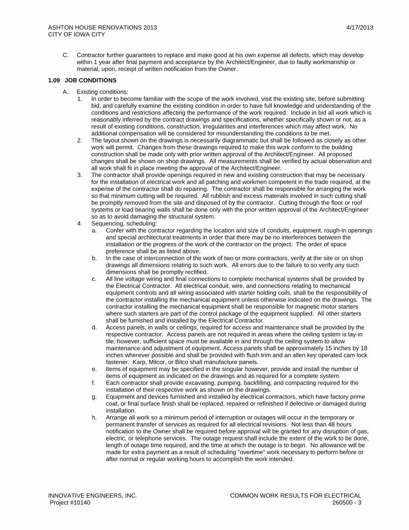
ASHTON HOUSE RENOVATIONS 2013 4/17/2013 CITY OF IOWA CITY
INNOVATIVE ENGINEERS, INC. COMMON WORK RESULTS FOR ELECTRICAL Project #10140 260500 - 3
C. Contractor further guarantees to replace and make good at his own expense all defects, which may develop within 1 year after final payment and acceptance by the Architect/Engineer, due to faulty workmanship or material, upon, receipt of written notification from the Owner.
1.09 JOB CONDITIONS
A. Existing conditions: 1. In order to become familiar with the scope of the work involved, visit the existing site, before submitting
bid, and carefully examine the existing condition in order to have full knowledge and understanding of the conditions and restrictions affecting the performance of the work required. Include in bid all work which is reasonably inferred by the contract drawings and specifications, whether specifically shown or not, as a result of existing conditions, construction, irregularities and interferences which may affect work. No additional compensation will be considered for misunderstanding the conditions to be met.
2. The layout shown on the drawings is necessarily diagrammatic but shall be followed as closely as other work will permit. Changes from these drawings required to make this work conform to the building construction shall be made only with prior written approval of the Architect/Engineer. All proposed changes shall be shown on shop drawings. All measurements shall be verified by actual observation and all work shall fit in place meeting the approval of the Architect/Engineer.
3. The contractor shall provide openings required in new and existing construction that may be necessary for the installation of electrical work and all patching and workmen competent in the trade required, at the expense of the contractor shall do repairing. The contractor shall be responsible for arranging the work so that minimum cutting will be required. All rubbish and excess materials involved in such cutting shall be promptly removed from the site and disposed of by the contractor. Cutting through the floor or roof systems or load bearing walls shall be done only with the prior written approval of the Architect/Engineer so as to avoid damaging the structural system.
4. Sequencing, scheduling: a. Confer with the contractor regarding the location and size of conduits, equipment, rough-in openings
and special architectural treatments in order that there may be no interferences between the installation or the progress of the work of the contractor on the project. The order of space preference shall be as listed above.
b. In the case of interconnection of the work of two or more contractors, verify at the site or on shop drawings all dimensions relating to such work. All errors due to the failure to so verify any such dimensions shall be promptly rectified.
c. All line voltage wiring and final connections to complete mechanical systems shall be provided by the Electrical Contractor. All electrical conduit, wire, and connections relating to mechanical equipment controls and all wiring associated with starter holding coils, shall be the responsibility of the contractor installing the mechanical equipment unless otherwise indicated on the drawings. The contractor installing the mechanical equipment shall be responsible for magnetic motor starters where such starters are part of the control package of the equipment supplied. All other starters shall be furnished and installed by the Electrical Contractor.
d. Access panels, in walls or ceilings, required for access and maintenance shall be provided by the respective contractor. Access panels are not required in areas where the ceiling system is lay-in tile; however, sufficient space must be available in and through the ceiling system to allow maintenance and adjustment of equipment. Access panels shall be approximately 15 inches by 18 inches wherever possible and shall be provided with flush trim and an allen key operated cam lock fastener. Karp, Milcor, or Bilco shall manufacture panels.
e. Items of equipment may be specified in the singular however, provide and install the number of items of equipment as indicated on the drawings and as required for a complete system.
f. Each contractor shall provide excavating, pumping, backfilling, and compacting required for the installation of their respective work as shown on the drawings.
g. Equipment and devices furnished and installed by electrical contractors, which have factory prime coat, or final surface finish shall be replaced, repaired or refinished if defective or damaged during installation.
h. Arrange all work so a minimum period of interruption or outages will occur in the temporary or permanent transfer of services as required for all electrical revisions. Not less than 48 hours notification to the Owner shall be required before approval will be granted for any disruption of gas, electric, or telephone services. The outage request shall include the extent of the work to be done, length of outage time required, and the time at which the outage is to begin. No allowance will be made for extra payment as a result of scheduling "overtime" work necessary to perform before or after normal or regular working hours to accomplish the work intended.

ASHTON HOUSE RENOVATIONS 2013 4/17/2013 CITY OF IOWA CITY
INNOVATIVE ENGINEERS, INC. COMMON WORK RESULTS FOR ELECTRICAL Project #10140 260500 - 4
i. Submit a "Sequence of Work Schedule" in respect to all temporary and permanent utility and service cutovers after final determination. This schedule shall be submitted for approval to the Architect/Engineer. The submittal shall designate priority order, service or utility affected, date of cutover, and time of day to start and finish.
PART 2 - PRODUCTS
2.01 RACEWAYS AND CONDUIT
A. Electrical Metallic Tubing (thin wall conduit, EMT) 1. All electrical metallic tubing shall be hot dipped galvanized coated, bear a NRTL label and shall conform
to Federal Specifications WW-C-563, ANSI C80-3, and UL 797. 2. Allied Tube and Conduit Corp., Republic Steel Corp., Wheatland Tube Co., Southwire Co. shall
manufacture all electrical metallic tubing, or Architect/Engineer approved equal.
B. Rigid Steel Conduit 1. All rigid steel conduits shall be hot dipped galvanized coated plus a secondary coat with galvanized
threads bears a NRTL label and shall conform to Federal Specifications WW-C-581d, ANSI C80-1. 2. Allied Tube and Conduit Corp., Republic Steel Corp, Wheatland Tube Co., Southwire Co. shall
manufacture all rigid steel conduits, or Architect/Engineer approved equal.
C. Intermediate Metal Conduit (IMC) 1. Intermediate metal conduit shall be hot dipped galvanized coated; galvanized coated threads bear a
NRTL label and shall conform to a NRTL standard for IMC. 2. Allied Tube and Conduit Corp., Republic Steel Corp., Wheatland Tube Co., Southwire Co. shall
manufacture intermediate metal conduit or Architect/Engineer approved equal.
D. Flexible Steel Conduit 1. All flexible steel conduits shall be hot dipped galvanized coated bears a NRTL label and shall conform to
Federal Specifications WW-C-566C. 2. Triangle PWC, American Flexible Conduit Co., Inc., Anaconda Metal Hose, shall manufacture all flexible
steel conduits or Architect/Engineer approved equal.
E. Liquid-tight Flexible Steel Conduit 1. All liquid-tight flexible steel conduit shall be interlocking flexible galvanized steel conduit with a special
polyvinyl chloride covering extruded over the flexible conduit to make the conduit liquid-tight resistant to moisture, oil, chemicals and corrosive fumes.
2. Anaconda Metal Hose, O-Z/Gedney, Triangle PWC shall manufacture all liquid-tight flexible steel conduits, or Architect/Engineer approved equal.
F. PVC Plastic Conduit 1. All PVC conduits shall be schedule 40 heavy wall duct. Conduit shall be composed of high impact PVC
(Polyvinyl Chloride-C-200 compound) and shall conform to industry NEMA Standards and be NRTL listed for underground and exposed use. Material shall have tensile strength of 7,000 psi at 73.4°F, flexural strength of 11,000 psi, compression strength of 8,600 psi, and minimum wall thickness in various sizes.
2. All conduit fittings, couplings, terminal adapters, junction boxes and necessary fittings shall be of the solvent welding material.
3. Carlon, Can-Tex, Triangle PWC Inc., shall manufacture all PVC conduits or Architect/Engineer approved equal.
2.02 CONDUIT HANGERS AND SUPPORTS
A. Surface Mounted Conduits 1. Rigid steel, IMC and EMT conduits 1 inch and smaller shall be supported with hot dipped galvanized one
hole steel pipe straps. 2. Rigid steel, IMC and EMT conduits 1 1/4 inches and larger shall be supported with hot dipped galvanized
one hole malleable iron pipe straps with pipe spacers. 3. Raco, Efcor, T & B, Appleton shall manufacture all pipe straps, or Architect/Engineer approved equal.
B. Suspended Conduits 1. Individual rigid steel, IMC and EMT conduit 1 inch and smaller shall be supported with conduit clips of
high carbon spring steel or zinc plated steel and support 100 pounds static load. Conduit clip shall be provided with 1/4” 20 threaded impression for attachment to 1/4 inch 20 threaded rod.
2. Individual rigid steel, IMC and EMT conduit 1 1/4 inches and larger shall be supported with stamped steel conduit clamps with 1/4 inch 20 bolt and nut and support 150 pounds static load. Provide conduit clamps with 3/8 inch 16 threaded boss for attachment to 3/8 inch 16 threaded rod.

ASHTON HOUSE RENOVATIONS 2013 4/17/2013 CITY OF IOWA CITY
INNOVATIVE ENGINEERS, INC. COMMON WORK RESULTS FOR ELECTRICAL Project #10140 260500 - 5
3. Support two or more rigid steel, IMC or EMT conduits adjacent to each other by 1 5/8 inches by 1 5/8 inches metal framing channel with minimum of two 1/2 inch 13 threaded rod at each end. Attach conduits to metal framing channel with electro-galvanized split pipe clamps with screw and nut.
4. Raco, Efcor, T & B, Appleton shall manufacture conduit clips and clamps, or Architect/Engineer approved equal.
5. Unistrut, Super Strut, Kindorf shall manufacture metal framing channel and split pipe clamps, or Architect/Engineer approved equal.
6. Conduit shall not be supported from plumbing lines or ductwork.
C. Anchors 1. Toggle bolts or spider type expansion anchors shall be used for hollow masonry. 2. Lead expansion anchors or preset anchors shall be used for solid masonry. 3. Self-drilling anchors or preset anchors shall be used for concrete. 4. Machine screws, bolts, self-tapping screws or welded studs shall be used for metal. 5. Wood screws shall be used for wood.
2.03 CONDUIT FITTINGS
A. All conduit fittings and box connectors shall be strong in construction and shall be of such material and finish as not to cause any chemical reaction between itself and the conduit or outlet box which it is fastened or supported.
B. All conduit fittings and box connectors shall be listed by a NRTL.
C. Insulated throat fittings are only required on conduits 2” and larger.
D. All conduit fittings, box connectors and lock nuts shall be of steel or malleable iron materials.
E. Fittings for EMT shall be set screw type, rain-tight and concrete-tight. Connectors, couplings, locknuts and other fittings for rigid steel heavy wall and IMC conduit shall be threaded type.
F. Connectors specified in this paragraph can be zinc plated steel in lieu of malleable iron.
G. Liquid-tight flexible conduit connectors shall be steel or malleable iron compression type with insulated throat and “O” ring assembly.
H. Fittings for flexible conduit or liquid-tight flexible conduit shall be of the straight 45 degree or 90 degree connectors and approved for grounding purposes.
I. Provide expansion joint fittings where expansion joints are shown on architectural drawings.
2.04 BOXES AND COVERS
A. All junction boxes pull boxes, fixture outlet boxes and switch boxes shall be listed by a NRTL.
B. All boxes and covers shall meet all requirements of the National Electrical Code.
C. All boxes and covers shall be made of code gauge steel.
D. All boxes shall be of proper size and shape for all conduits and conductors entering them.
E. Install device boxes with bracket attached to box and wall stud to eliminate movement of box in wall.
F. All boxes installed in poured concrete, block, brick or tile shall be masonry type.
G. All multiple gang switch boxes of more than three-gang shall be solid gang box.
H. Surface mount boxes on the ceiling are note required to be FS or FD type boxes. Stamped steel boxes are acceptable for boxes on the ceiling.
I. Where two or more conduits enter a box, the minimum size of boxes shall be 4 inches by 4 inches by 1 1/2 inches minimum depth. For single device installation, install square cut single device cover.
J. Install all device boxes with square cut device covers for number of devices required.
K. All boxes shall have tapped hole for 10-32 ground screw.
L. Raco, Steel City, Appleton shall manufacture boxes and covers, or Architect/Engineer approved equal.
2.05 CABLE AND WIRE
A. All wire shall have copper conductors and be listed by a NRTL.

ASHTON HOUSE RENOVATIONS 2013 4/17/2013 CITY OF IOWA CITY
INNOVATIVE ENGINEERS, INC. COMMON WORK RESULTS FOR ELECTRICAL Project #10140 260500 - 6
B. Service entrance conductors shall be 600 volts insulation type XHHW-2 90°C. All other wire shall be 600 volts insulation type THWN 90°C insulation for sizes No. 6 to 500 MCM and type THHN 90°C insulation for sizes No. 12 to No. 8.
C. Under ground wire to pole mounted light fixtures shall be type USE in conduit.
D. Provide long barrel, NEMA 2 hole copper compression connectors for all cables connected to the padmounted transformer. Make all connections with stainless steel hardware.
E. Minimum wire size shall be No. 12 except for internal fixture wire that shall be minimum size of No. 14 type AF, CF or TFN, 300 volt.
F. All wire (excluding fire alarm and low voltage wiring) shall be stranded, including #12 AWG and #10 AWG branch circuit wiring.
G. All branch circuit wiring and feeder cables for circuits over 20 amperes shall be sized as noted on the drawings. If size is not specifically noted, size all branch circuit wiring and feeder cables in accordance with the National Electrical Code.
H. Cable and wire not installed in conduit shall be #12 AWG SO or SJO type grounded cord. Cord shall terminate at junction boxes and devices with strain relief cord grids.
I. Triangle, Crescent, Colleyer, and General Cable shall manufacture all wire, or Architect/Engineer approved equal.
2.06 METAL CLAD CABLE
A. MC cable is not allowed.
2.07 ELECTRICAL WIRING DEVICES
A. All devices are specified as having black finish in wood, white finish if in drywall. The Architect/Engineer reserves the right to change the color.
B. Furnish all special outlets with mating caps with cord grips.
C. Schedule of all electrical devices: 1. Single Pole Switch - 20 amperes at 120 volts
a. Hubbell DS120 2. Three Way Switch - 20 amperes at 120 volts
a. Hubbell DS320 3. Four Way Switch - 20 amperes at 120 volts
a. Hubbell DS420 4. Duplex Convenience Outlet - 20 amperes at 120 volts
a. Hubbell DR20 5. Duplex Convenience Tamper Resistant Outlet - 20 amperes at 120 volts
a. Hubbell D20TR 6. Duplex Convenience Outlet - GFI - 20 amperes at 120 volts
a. Hubbell GF20
D. Forward submittals to Architect/Engineer for review.
2.08 WIRING DEVICE PLATES
A. All device plates shall be furnished with proper openings for the device with which it is being used. Where required, multiple gang plates for correct combination shall be used.
B. Device plates shall fit tight against the finished walls and shall completely cover the openings in the walls for the boxes.
C. Device plates shall be attached and adjusted so they finish straight and level.
D. Where more than one light switch is gained or a light switch and outlet are installed in a two gang box, install multiple gang device plates with proper openings.
E. Provide 1/2 inch raised galvanized device covers where used for exposed conduit work.
F. All device plates shall be black if located on wood and white if located on drywall, with the proper openings for the device with which they are being used.
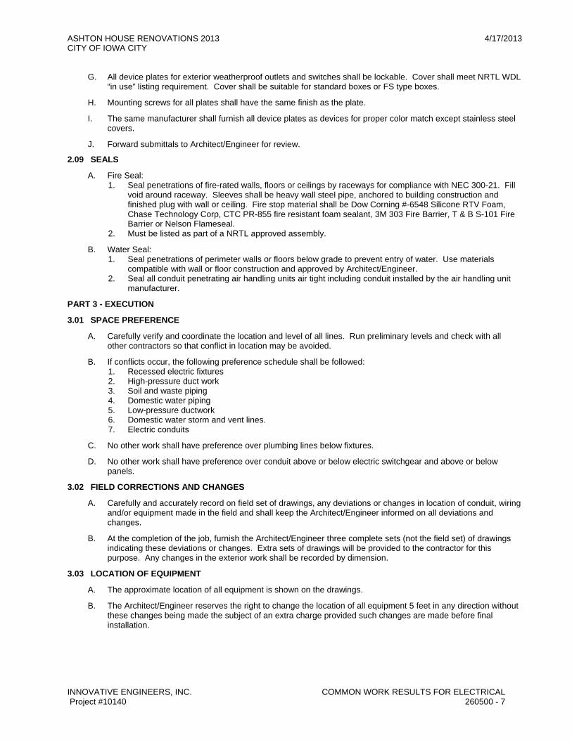
ASHTON HOUSE RENOVATIONS 2013 4/17/2013 CITY OF IOWA CITY
INNOVATIVE ENGINEERS, INC. COMMON WORK RESULTS FOR ELECTRICAL Project #10140 260500 - 7
G. All device plates for exterior weatherproof outlets and switches shall be lockable. Cover shall meet NRTL WDL “in use” listing requirement. Cover shall be suitable for standard boxes or FS type boxes.
H. Mounting screws for all plates shall have the same finish as the plate.
I. The same manufacturer shall furnish all device plates as devices for proper color match except stainless steel covers.
J. Forward submittals to Architect/Engineer for review.
2.09 SEALS
A. Fire Seal: 1. Seal penetrations of fire-rated walls, floors or ceilings by raceways for compliance with NEC 300-21. Fill
void around raceway. Sleeves shall be heavy wall steel pipe, anchored to building construction and finished plug with wall or ceiling. Fire stop material shall be Dow Corning #-6548 Silicone RTV Foam, Chase Technology Corp, CTC PR-855 fire resistant foam sealant, 3M 303 Fire Barrier, T & B S-101 Fire Barrier or Nelson Flameseal.
2. Must be listed as part of a NRTL approved assembly.
B. Water Seal: 1. Seal penetrations of perimeter walls or floors below grade to prevent entry of water. Use materials
compatible with wall or floor construction and approved by Architect/Engineer. 2. Seal all conduit penetrating air handling units air tight including conduit installed by the air handling unit
manufacturer.
PART 3 - EXECUTION
3.01 SPACE PREFERENCE
A. Carefully verify and coordinate the location and level of all lines. Run preliminary levels and check with all other contractors so that conflict in location may be avoided.
B. If conflicts occur, the following preference schedule shall be followed: 1. Recessed electric fixtures 2. High-pressure duct work 3. Soil and waste piping 4. Domestic water piping 5. Low-pressure ductwork 6. Domestic water storm and vent lines. 7. Electric conduits
C. No other work shall have preference over plumbing lines below fixtures.
D. No other work shall have preference over conduit above or below electric switchgear and above or below panels.
3.02 FIELD CORRECTIONS AND CHANGES
A. Carefully and accurately record on field set of drawings, any deviations or changes in location of conduit, wiring and/or equipment made in the field and shall keep the Architect/Engineer informed on all deviations and changes.
B. At the completion of the job, furnish the Architect/Engineer three complete sets (not the field set) of drawings indicating these deviations or changes. Extra sets of drawings will be provided to the contractor for this purpose. Any changes in the exterior work shall be recorded by dimension.
3.03 LOCATION OF EQUIPMENT
A. The approximate location of all equipment is shown on the drawings.
B. The Architect/Engineer reserves the right to change the location of all equipment 5 feet in any direction without these changes being made the subject of an extra charge provided such changes are made before final installation.
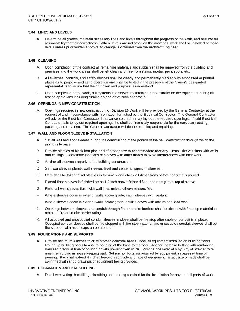
ASHTON HOUSE RENOVATIONS 2013 4/17/2013 CITY OF IOWA CITY
INNOVATIVE ENGINEERS, INC. COMMON WORK RESULTS FOR ELECTRICAL Project #10140 260500 - 8
3.04 LINES AND LEVELS
A. Determine all grades, maintain necessary lines and levels throughout the progress of the work, and assume full responsibility for their correctness. Where levels are indicated on the drawings, work shall be installed at those levels unless prior written approval to change is obtained from the Architect/Engineer.
3.05 CLEANING
A. Upon completion of the contract all remaining materials and rubbish shall be removed from the building and premises and the work areas shall be left clean and free from stains, mortar, paint spots, etc.
B. All switches, controls, and safety devices shall be clearly and permanently marked with embossed or printed plates as to purpose and as to operation and shall be tested in the presence of the Owner's designated representative to insure that their function and purpose is understood.
C. Upon completion of the work, put systems into service maintaining responsibility for the equipment during all testing operations including turning on and off of such apparatus.
3.06 OPENINGS IN NEW CONSTRUCTION
A. Openings required in new construction for Division 26 Work will be provided by the General Contractor at the request of and in accordance with information furnished by the Electrical Contractor. The General Contractor will advise the Electrical Contractor in advance so that he may lay out the required openings. If said Electrical Contractor fails to lay out required openings, he shall be financially responsible for the necessary cutting, patching and repairing. The General Contractor will do the patching and repairing.
3.07 WALL AND FLOOR SLEEVE INSTALLATION
A. Set all wall and floor sleeves during the construction of the portion of the new construction through which the piping is to pass.
B. Provide sleeves of black iron pipe and of proper size to accommodate raceway. Install sleeves flush with walls and ceilings. Coordinate locations of sleeves with other trades to avoid interferences with their work.
C. Anchor all sleeves properly to the building construction.
D. Set floor sleeves plumb, wall sleeves level and center all piping in sleeves.
E. Care shall be taken to set sleeves in formwork and check all dimensions before concrete is poured.
F. Extend floor sleeves in finished areas 1/2 inch above finished floor and neatly level top of sleeve.
G. Finish all wall sleeves flush with wall lines unless otherwise specified.
H. Where sleeves occur in exterior walls above grade, caulk sleeves with sealant.
I. Where sleeves occur in exterior walls below grade, caulk sleeves with oakum and lead wool.
J. Openings between sleeves and conduit through fire or smoke barriers shall be closed with fire stop material to maintain fire or smoke barrier rating.
K. All occupied and unoccupied conduit sleeves in closet shall be fire stop after cable or conduit is in place. Occupied conduit sleeves shall be fire stopped with fire stop material and unoccupied conduit sleeves shall be fire stopped with metal caps on both ends.
3.08 FOUNDATIONS AND SUPPORTS
A. Provide minimum 4 inches thick reinforced concrete bases under all equipment installed on building floors. Rough up building floors to assure bonding of the base to the floor. Anchor the base to floor with reinforcing bars set in floor at time of pouring or with power driven studs. Provide one layer of 6 by 6 by #6 welded wire mesh reinforcing in house keeping pad. Set anchor bolts, as required by equipment, in bases at time of pouring. Pad shall extend 4 inches beyond each side and face of equipment. Exact size of pads shall be confirmed with shop drawings of equipment being provided.
3.09 EXCAVATION AND BACKFILLING
A. Do all excavating, backfilling, sheathing and bracing required for the installation for any and all parts of work.
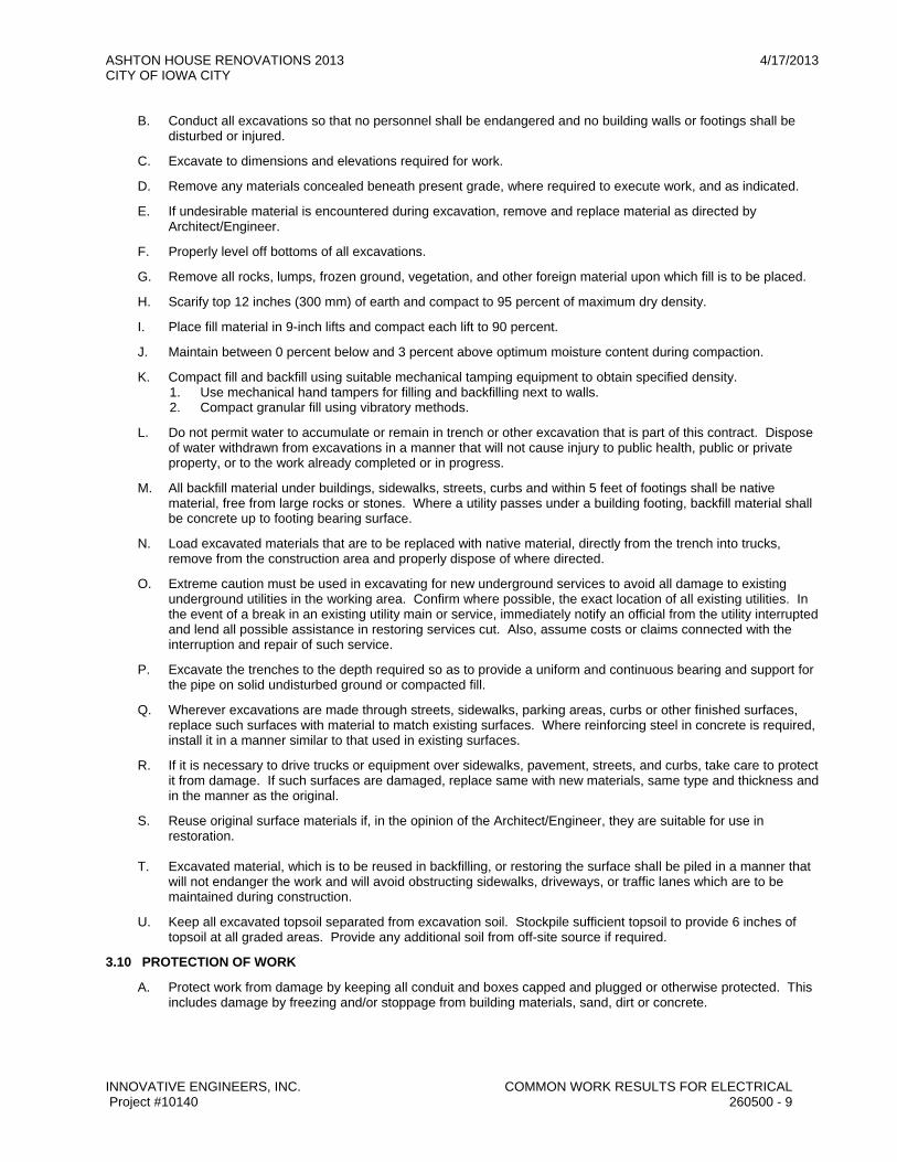
ASHTON HOUSE RENOVATIONS 2013 4/17/2013 CITY OF IOWA CITY
INNOVATIVE ENGINEERS, INC. COMMON WORK RESULTS FOR ELECTRICAL Project #10140 260500 - 9
B. Conduct all excavations so that no personnel shall be endangered and no building walls or footings shall be disturbed or injured.
C. Excavate to dimensions and elevations required for work.
D. Remove any materials concealed beneath present grade, where required to execute work, and as indicated.
E. If undesirable material is encountered during excavation, remove and replace material as directed by Architect/Engineer.
F. Properly level off bottoms of all excavations.
G. Remove all rocks, lumps, frozen ground, vegetation, and other foreign material upon which fill is to be placed.
H. Scarify top 12 inches (300 mm) of earth and compact to 95 percent of maximum dry density.
I. Place fill material in 9-inch lifts and compact each lift to 90 percent.
J. Maintain between 0 percent below and 3 percent above optimum moisture content during compaction.
K. Compact fill and backfill using suitable mechanical tamping equipment to obtain specified density. 1. Use mechanical hand tampers for filling and backfilling next to walls. 2. Compact granular fill using vibratory methods.
L. Do not permit water to accumulate or remain in trench or other excavation that is part of this contract. Dispose of water withdrawn from excavations in a manner that will not cause injury to public health, public or private property, or to the work already completed or in progress.
M. All backfill material under buildings, sidewalks, streets, curbs and within 5 feet of footings shall be native material, free from large rocks or stones. Where a utility passes under a building footing, backfill material shall be concrete up to footing bearing surface.
N. Load excavated materials that are to be replaced with native material, directly from the trench into trucks, remove from the construction area and properly dispose of where directed.
O. Extreme caution must be used in excavating for new underground services to avoid all damage to existing underground utilities in the working area. Confirm where possible, the exact location of all existing utilities. In the event of a break in an existing utility main or service, immediately notify an official from the utility interrupted and lend all possible assistance in restoring services cut. Also, assume costs or claims connected with the interruption and repair of such service.
P. Excavate the trenches to the depth required so as to provide a uniform and continuous bearing and support for the pipe on solid undisturbed ground or compacted fill.
Q. Wherever excavations are made through streets, sidewalks, parking areas, curbs or other finished surfaces, replace such surfaces with material to match existing surfaces. Where reinforcing steel in concrete is required, install it in a manner similar to that used in existing surfaces.
R. If it is necessary to drive trucks or equipment over sidewalks, pavement, streets, and curbs, take care to protect it from damage. If such surfaces are damaged, replace same with new materials, same type and thickness and in the manner as the original.
S. Reuse original surface materials if, in the opinion of the Architect/Engineer, they are suitable for use in restoration.
T. Excavated material, which is to be reused in backfilling, or restoring the surface shall be piled in a manner that
will not endanger the work and will avoid obstructing sidewalks, driveways, or traffic lanes which are to be maintained during construction.
U. Keep all excavated topsoil separated from excavation soil. Stockpile sufficient topsoil to provide 6 inches of topsoil at all graded areas. Provide any additional soil from off-site source if required.
3.10 PROTECTION OF WORK
A. Protect work from damage by keeping all conduit and boxes capped and plugged or otherwise protected. This includes damage by freezing and/or stoppage from building materials, sand, dirt or concrete.

ASHTON HOUSE RENOVATIONS 2013 4/17/2013 CITY OF IOWA CITY
INNOVATIVE ENGINEERS, INC. COMMON WORK RESULTS FOR ELECTRICAL Project #10140 260500 - 10
3.11 INSTALLATION
A. Coordinate with other contractors engaged in project. Execute work in a manner not to interfere with other contractors or Owner's operation.
B. Coordinate work with other contractors regarding location and size of pipes, raceways, ducts, openings, switches, outlets, so there is no interference between installations or of progress of any contractor.
C. Install all equipment with ample space allowed for removal, repair, or changes to equipment. Provide ready accessibility to removable parts of equipment and to all wiring without moving equipment installed or already in place. Provide access panels for all devices installed above non-accessible ceilings or within walls or partitions.
D. At project completion, clean all equipment to the original finish. Remove all shipping labels.
E. Provide touch-up painting of all equipment marred in any way during shipment or installation.
3.12 INSTALLATION OF RACEWAYS AND CONDUITS
A. All raceways shall be concealed in wall construction and/or above ceiling construction except in mechanical equipment rooms, where it may be exposed at the ceiling or on walls.
B. There shall not be any branch circuit conduits installed horizontally in the concrete floor slabs throughout the building, except where specifically shown on the drawings.
C. In mechanical and electrical equipment spaces, expose ceiling outlets and conduit with due consideration to ventilating ducts and mechanical piping. Where numerous ducts occur, install conduits and outlets after ventilating ducts. Puncturing of ductwork or hanging equipment such as light fixtures, ceiling hangers, conduit, from ductwork, is prohibited, unless specifically noted otherwise.
D. Lay out all partitions on the project, for proper rough-in locations of all boxes and conduits. Verify all partition locations, door swings, cabinet locations before roughing in, and make any/all changes necessary to ensure that all switches, outlets, systems equipment, rough-ins are located properly. Any changes necessary in locations and rough-ins, due to a partition change and this contractor's failure to coordinate and verify same, shall be made.
E. The routing of conduit shown on the drawings is diagrammatic only, and this contractor shall install conduit as required to complete the systems so as not to interfere with other trades in both elevation and location.
F. The location of all conduit, boxes, fixtures, etc., in all areas finished and unfinished shall be coordinated.
G. Route conduit through roof openings for piping and ductwork where possible. Provide flashing making waterproof joints where conduits pass through roof or roofing membrane.
H. Provide conduit expansion joints at building expansion joints for conduit runs 1 1/2 inches and larger. Provide conduit expansion joints or flexible conduit connection at building expansion joints for conduits less than 1 1/2 inches.
I. Conduit shall be a minimum of 3/4 inch unless otherwise noted on the drawings.
J. All conduit bends shall be long radius with not more than the equivalent of three 90-degree bends between pull points.
K. Provide all open ends of conduit with bush caps to exclude any foreign material during construction.
L. All conduits installed in or under concrete or underground shall have joints sealed to exclude all water or other foreign material.
M. Coordinate the installation of all conduits in mechanical equipment spaces or where large amounts of ductwork and piping are present, with the other contractors so as to avoid interferences.
N. Unless otherwise noted on the drawings, size all conduits according to the National Electrical Code.
O. Install all exposed conduits parallel or perpendicular to adjacent walls, ceilings or floors.
P. All conduit couplings and fittings shall be made up wrench tight.
Q. Make all conduit systems mechanically and electrically continuous from source of current to all outlets, and ground in accordance with the National Electrical Code.

ASHTON HOUSE RENOVATIONS 2013 4/17/2013 CITY OF IOWA CITY
INNOVATIVE ENGINEERS, INC. COMMON WORK RESULTS FOR ELECTRICAL Project #10140 260500 - 11
R. Where building construction or other conditions make it impossible to use standard threaded couplings, install watertight threaded unions.
S. Install rigid steel conduit for the following: 1. All conduit in poured concrete construction (unless noted as PVC). 2. All conduit underground (unless noted as PVC). 3. All conduit exposed in exterior areas. 4. All conduit installed through foundation or basement wall, below grade, to a minimum of 10'0” beyond
wall. 5. All service entrance conduit and all exterior conduit larger than 2” trade size.
T. Install electrical metallic tubing (thin wall) conduit for the following: 1. All conduits in block, brick, tile or stud walls. 2. All feeders for panelboards and distribution equipment. 3. All conduit exposed in interior areas.
U. Install flexible steel conduit for the following: 1. Final connections for all recessed lighting fixtures (fluorescent and incandescent). 2. All vibration generating equipment except where flexible liquid-tight is specifically called for. 3. A maximum length of flexible steel conduit shall be limited to 6'0”.
V. Install liquid-tight flexible steel conduit for the following: 1. Final connections to all motors, except exhaust fans in ceiling space and wall 1/8 horsepower and less. 2. All vibration generating equipment exposed to exterior conditions. 3. Maximum length of liquid-tight flexible conduit shall be limited to 6'0”.
W. Install PVC conduit for the following: 1. All conduit for underground exterior circuits 2” and smaller. PVC conduit shall be complete with all
accessories, such as, couplings, male and female adapters, expansion couplings, elbows and support straps. Install one expansion coupling for every 100 feet of run, or in any run solidly connected at both ends. Use solvent welding cement recommended by the duct manufacturer, for all conduit terminations at fittings of all types to seal and secure the connections. Support the plastic conduit horizontal conduit runs 4 feet on center and vertical runs every 8 feet.
X. Communications 1. Minimum communications raceway size to be 1" conduit, unless otherwise noted on drawings. 2. Provide one conduit from each communications box. Horizontal conduit runs between wall boxes are not
allowed. 3. Provide insulated grounding bushings on end of conduit. 4. Provide flush two-gang box with single gang plaster ring for each communications outlet or as noted on
drawings. 5. Conduit bends to be no less than 10 times outside diameter of conduit. 6. Conduits shall have no more that (2) 90 degree bends or total of 180 degree bends or offsets without a
pull box. Pull boxes shall be installed in accessible locations. 7. No underslab installations allowed.
3.13 RACEWAY SUPPORTS AND HANGERS
A. Securely fasten raceways in place and support from ceiling or walls. 1. Maximum Spacing of Supports Material
a. 1/2" through 1” trade size 6 feet b. 1 1/4" through 1 1/2" trade size 8 feet c. 2” through 4” trade size 10 feet d. Flexible metal conduit 4 1/2 feet
B. Support IMC or EMT conduit within three feet of every outlet box, junction box, pull box, cabinet or termination. Support flexible conduit within 12 inches of every outlet box or fitting.
C. Support vertical runs or conduits at each floor level and at interval not to exceed ten feet.
D. Support conduits by pipe straps, wall brackets, hangers, or ceiling trapeze. The use of perforated iron on wire for supporting conduits is prohibited. Fasten with wood screws or screw nails to wood; by toggle bolts on hollow masonry units, by concrete inserts, or expansion steel conduits on steel. Do not weld conduits or pipe straps to steel structures unless specifically indicated.
E. The load applied to fasteners shall not exceed one-third the proof test load of the fasteners.
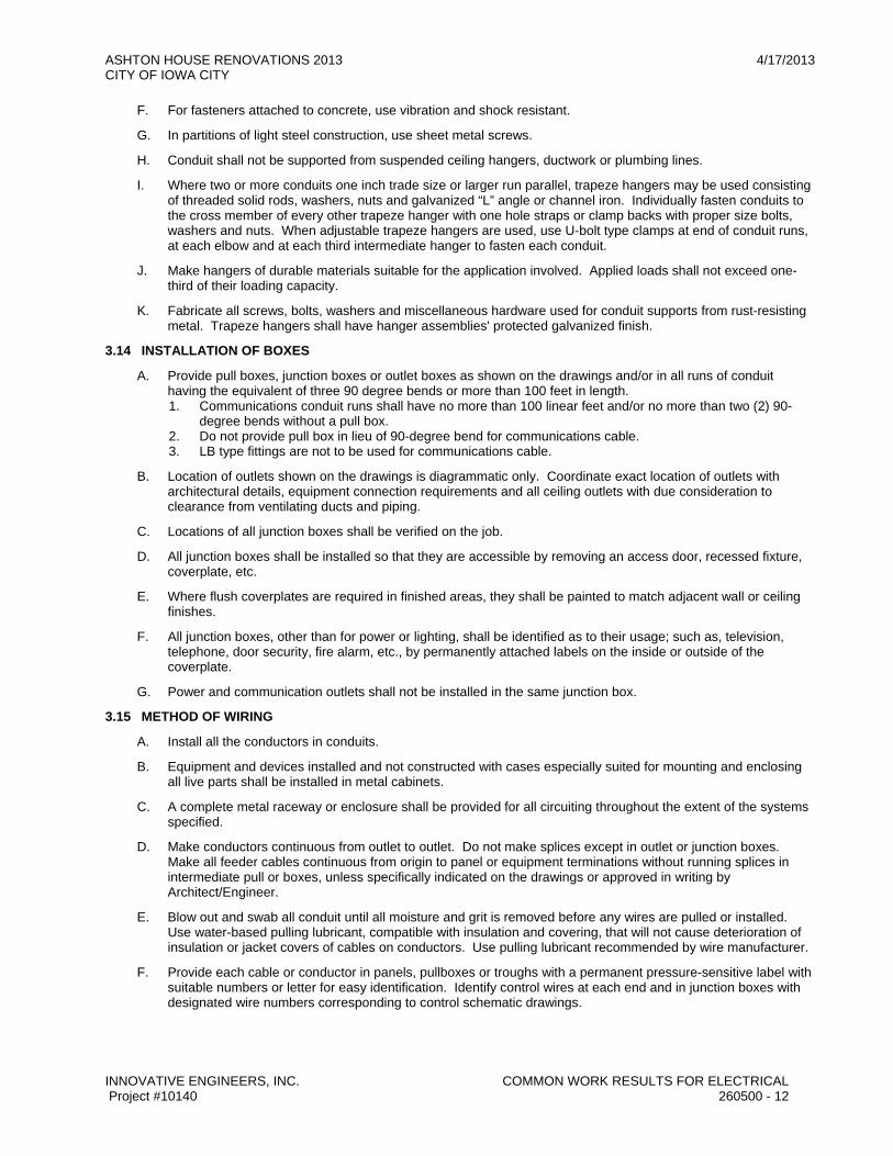
ASHTON HOUSE RENOVATIONS 2013 4/17/2013 CITY OF IOWA CITY
INNOVATIVE ENGINEERS, INC. COMMON WORK RESULTS FOR ELECTRICAL Project #10140 260500 - 12
F. For fasteners attached to concrete, use vibration and shock resistant.
G. In partitions of light steel construction, use sheet metal screws.
H. Conduit shall not be supported from suspended ceiling hangers, ductwork or plumbing lines.
I. Where two or more conduits one inch trade size or larger run parallel, trapeze hangers may be used consisting of threaded solid rods, washers, nuts and galvanized “L” angle or channel iron. Individually fasten conduits to the cross member of every other trapeze hanger with one hole straps or clamp backs with proper size bolts, washers and nuts. When adjustable trapeze hangers are used, use U-bolt type clamps at end of conduit runs, at each elbow and at each third intermediate hanger to fasten each conduit.
J. Make hangers of durable materials suitable for the application involved. Applied loads shall not exceed one-third of their loading capacity.
K. Fabricate all screws, bolts, washers and miscellaneous hardware used for conduit supports from rust-resisting metal. Trapeze hangers shall have hanger assemblies' protected galvanized finish.
3.14 INSTALLATION OF BOXES
A. Provide pull boxes, junction boxes or outlet boxes as shown on the drawings and/or in all runs of conduit having the equivalent of three 90 degree bends or more than 100 feet in length. 1. Communications conduit runs shall have no more than 100 linear feet and/or no more than two (2) 90-
degree bends without a pull box. 2. Do not provide pull box in lieu of 90-degree bend for communications cable. 3. LB type fittings are not to be used for communications cable.
B. Location of outlets shown on the drawings is diagrammatic only. Coordinate exact location of outlets with architectural details, equipment connection requirements and all ceiling outlets with due consideration to clearance from ventilating ducts and piping.
C. Locations of all junction boxes shall be verified on the job.
D. All junction boxes shall be installed so that they are accessible by removing an access door, recessed fixture, coverplate, etc.
E. Where flush coverplates are required in finished areas, they shall be painted to match adjacent wall or ceiling finishes.
F. All junction boxes, other than for power or lighting, shall be identified as to their usage; such as, television, telephone, door security, fire alarm, etc., by permanently attached labels on the inside or outside of the coverplate.
G. Power and communication outlets shall not be installed in the same junction box.
3.15 METHOD OF WIRING
A. Install all the conductors in conduits.
B. Equipment and devices installed and not constructed with cases especially suited for mounting and enclosing all live parts shall be installed in metal cabinets.
C. A complete metal raceway or enclosure shall be provided for all circuiting throughout the extent of the systems specified.
D. Make conductors continuous from outlet to outlet. Do not make splices except in outlet or junction boxes. Make all feeder cables continuous from origin to panel or equipment terminations without running splices in intermediate pull or boxes, unless specifically indicated on the drawings or approved in writing by Architect/Engineer.
E. Blow out and swab all conduit until all moisture and grit is removed before any wires are pulled or installed. Use water-based pulling lubricant, compatible with insulation and covering, that will not cause deterioration of insulation or jacket covers of cables on conductors. Use pulling lubricant recommended by wire manufacturer.
F. Provide each cable or conductor in panels, pullboxes or troughs with a permanent pressure-sensitive label with suitable numbers or letter for easy identification. Identify control wires at each end and in junction boxes with designated wire numbers corresponding to control schematic drawings.

ASHTON HOUSE RENOVATIONS 2013 4/17/2013 CITY OF IOWA CITY
INNOVATIVE ENGINEERS, INC. COMMON WORK RESULTS FOR ELECTRICAL Project #10140 260500 - 13
G. Provide wires and cables entering equipment or panels with enough slack to eliminate stretched, angular connection. Neatly arrange wiring, bundle and fan out to termination panels. Make minimum bending radius for conductors in accord with National Electrical Code.
H. Support all conductors in vertical raceways in accord with National Electrical Code.
I. Leave at least six-inch loops or ends at each outlet for installation of devices or fixtures. Roll up all wires in outlet boxes not for connection to fixture or device at that outlet, connect together and tape.
J. Size all branch circuit wiring for circuits over 20 amperes as shown on the drawings and/or as required by the National Electrical Code. All home run branch circuit wiring from the first outlet, fixture or device on 120 volt, 1 phase, or 277 volt, 1 phase circuit to the panelboard shall conform to the following wire sizes for amp circuits unless otherwise noted on the drawings: 1. 120-VOLT CIRCUITS
a. 0 to 50 feet #12 wire b. 51 to 100 feet #10 wire c. 101 to 150 feet # 8 wire d. 151 to 200 feet #6 wire
K. Clarification to the color-coding of conductors is as follows: For all voltages and systems equipment grounds shall be green, isolated grounds shall be green with yellow stripe or with yellow tape bands and travelers for 3-way switches shall be violet.
L. At the Electrical Contractor's option, the three phase power circuits and feeder cables can be installed with color-coded conductors or with three conductors of the same color. If they are installed with the same color of insulation, mark with colored tape in the panelboard and starter.
M. Phase all distribution equipment left-to-right, A, B, and C for continuity of phasing throughout the installation. N. All stranded cables shall terminate into mechanical type or compression type lugs at termination points.
O. Neatly group all circuits in all distribution equipment and tie with Seine Twine, Ty-Rap or Wrap Tabs.
P. Special care shall be taken to balance connections of circuit wires on different phases at the lighting panelboards using distinguishing colors for identifying the particular phase on which the circuit belongs.
Q. In general, lighting and outlet circuits shall distribute from single pole 20-ampere breakers, 2 wire with solid neutral. Where noted on drawings, run single phase or 3 phase power circuits from two or three pole breakers.
R. A separate neutral conductor shall be pulled for each phase conductor for all 120 volt and 277 volt branch circuits. Common neutrals are not allowed.
3.16 WIRING JOINTS
A. Joints in conductors shall be as few in number as practicable and where they are necessary they shall be mechanically strong, well made and shall provide complete electrical contact.
B. Joints shall be so made that they have an electrical resistance not in excess of that of two feet of the conductor.
C. Make all branch circuit joints for wire up to and including No. 10 AWG with expandable steel spring and polypropylene body type connectors and wire nuts manufactured by Ideal, Scotch, Buchanan or Architect/Engineer approved equal.
D. Make all wire splices in wire No. 6 and larger with mechanical compression crimp type connectors of proper size and wire configuration. Cover all connectors with a minimum of three layers of 600 volts tape or heat shrinkable insulation equivalent to 150 percent conductor insulation.
E. Neutral conductors in outlet boxes at receptacles shall be jointed and pigtailed to the outlet. The removal of a receptacle from the circuit shall not affect the continuity of the neutral conductor.
3.17 HEIGHTS OF WALL SWITCHES AND RECEPTACLES
A. Determine the exact height of each light, receptacle outlets, and outlet boxes on the premises and examine the general drawings and details to see that outlets are properly spaced and located with relation to the interior finish and treatment.

ASHTON HOUSE RENOVATIONS 2013 4/17/2013 CITY OF IOWA CITY
INNOVATIVE ENGINEERS, INC. COMMON WORK RESULTS FOR ELECTRICAL Project #10140 260500 - 14
B. In order that all outlets may be located in proper relation to paneling and decorated areas, become familiar with the details of these areas. Consult with the other contractors on the project and procure all details of the various areas so as to make the outlet boxes and panelboards come in proper relation to the work of all other contractors. Be responsible for the exact and proper location of the various portions of work. Such work must be entirely satisfactory to the Architect/Engineer.
C. Mounting heights of devices shall comply with ADA. The following is a list of mounting heights for equipment: 1. Locate wall switches 3'6” above the floor, except where special treatment requires a higher or lower
setting. 2. Locate receptacles as follows:
a. In general, locate 18 inches above finished floor except as hereinafter specified or as indicated on the drawings.
b. In block walls, locate either in the bottom or top of the nearest block course. c. In brick walls, mount in the horizontal position, in the fourth brick course. d. In spaces where noted to be above counters, mount in the horizontal position, 4 inches from
backsplash to bottom of box. e. In rooms that house mechanical and electrical equipment, locate 40 inches above finished floor. f. Locate weatherproof receptacles 24 inches above finished grade.
3. F.A. Speakers and Visual Indicators: 84” above finished floor to bottom of device. 4. F.A. Pull Stations: 3'6” above finished floor to center of device. 5. Disconnect Switches: 5'0” above finished floor. 6. Manual and Magnetic Starters or Pushbutton Controls: 5'0” above finished floor. 7. Telephone/Data Outlets: Same as receptacles above.
D. All of the above mounting heights shall be held as near as possible to the center line of the equipment.
E. The above list is general in nature. Examine all Architectural Drawings and consult with the Architect/Engineer and vary mounting heights as directed.
3.18 TESTING 600 VOLT
A. After wires and cables are in place and before connection to the devices and equipment is made, test the system for shorts and grounds by means of an approved type of constant potential “Megger”, which is to be furnished by the Electrical Contractor.
B. Remove and replace all hot wires if shorted or grounded.
END OF SECTION

ASHTON HOUSE RENOVATIONS 2013 4/17/2013 CITY OF IOWA CITY
INNOVATIVE ENGINEERS, INC. GROUNDING AND BONDING FOR ELECTRICAL SYSTEMS Project # 10140 260526 - 1
SECTION 26 05 26 GROUNDING AND BONDING FOR ELECTRICAL SYSTEMS
PART 1 - GENERAL
1.01 WORK INCLUDES
A. Completely grounded system. Electrical equipment, conduits, supports, cabinets and panels shall be grounded in accord with NEC and as shown on the drawings.
1.02 QUALITY ASSURANCE
A. Codes & Standards: 1. UL listed. 2. NFPA 70 (NEC), 2008 3. NEMA 4. NEC Article 250
PART 2 - PRODUCTS
2.01 MATERIALS
A. Ground Grid: 1. Ground rods shall be 3/4" diameter, 10 feet long, copper-plated type. 2. Grounding conductors installed in direct contact with the earth shall be insulated Type USE. 3. Connections shall be exothermic welding process.
B. Ground Water Main: 1. Ground to water main pipe. Provide jumper across water meter.
C. Equipment: 1. All grounding clamps and devices shall be of type approved by UL. 2. Approved Manufacturers:
a. Thomas & Betts Co. b. O.Z. c. Burndy
PART 3 - EXECUTION
3.01 INSTALLATION
A. Electrical System shall be grounded. Grounding shall be in accord with NEC 250 and NEC 680. By reference herein, NEC Sections 250 and 680 shall become a part of this specification and shall be adhered to strictly.
B. All conduit, raceways, equipment, enclosures, panel housings, fixture housings, bus ducts, shall be grounded back to the service equipment location utilizing the continuous metallic conduit system as the grounding means. Discontinuity of the metallic conduit grounding system will not be acceptable.
C. All connections to motors, receptacles and equipment shall contain a separate grounding conductor bonded to the panelboard grounding bus at one end and the motor frame, receptacles, or equipment at the other end.
D. Provide a ground wire in all lighting circuits. Ground all lighting equipment.
E. Provide a ground wire for all 120V receptacle outlet circuits.
F. See Section 26 05 00 for ground type duplex receptacle.
G. See Section 26 05 00 for ground fault interrupting receptacles in wet locations.
H. See Sections 26 05 00 for fittings for continuous conduit grounding system.
I. All ground wires shall be run in conduit except where otherwise indicated on the drawings.
J. Color code of ground wire shall be green.

ASHTON HOUSE RENOVATIONS 2013 4/17/2013 CITY OF IOWA CITY
INNOVATIVE ENGINEERS, INC. GROUNDING AND BONDING FOR ELECTRICAL SYSTEMS Project # 10140 260526 - 2
K. Exterior grade mounted equipment shall have enclosures grounded directly to a separate driven ground at the equipment in addition to the building ground connection. This includes grade mounted light fixtures.
3.02 TESTING
A. Reference Section 26 08 00 for requirements.
END OF SECTION
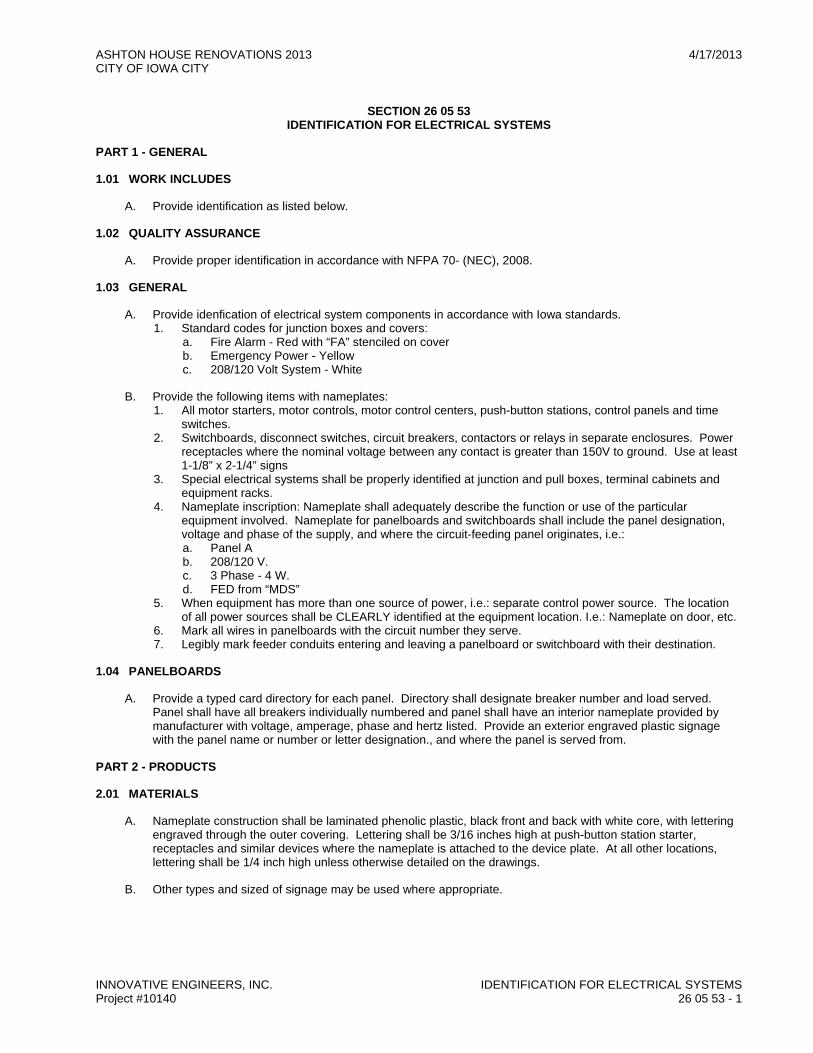
ASHTON HOUSE RENOVATIONS 2013 4/17/2013 CITY OF IOWA CITY
INNOVATIVE ENGINEERS, INC. IDENTIFICATION FOR ELECTRICAL SYSTEMS Project #10140 26 05 53 - 1
SECTION 26 05 53
IDENTIFICATION FOR ELECTRICAL SYSTEMS
PART 1 - GENERAL
1.01 WORK INCLUDES
A. Provide identification as listed below.
1.02 QUALITY ASSURANCE
A. Provide proper identification in accordance with NFPA 70- (NEC), 2008.
1.03 GENERAL
A. Provide idenfication of electrical system components in accordance with Iowa standards. 1. Standard codes for junction boxes and covers:
a. Fire Alarm - Red with “FA” stenciled on cover b. Emergency Power - Yellow c. 208/120 Volt System - White
B. Provide the following items with nameplates: 1. All motor starters, motor controls, motor control centers, push-button stations, control panels and time
switches. 2. Switchboards, disconnect switches, circuit breakers, contactors or relays in separate enclosures. Power
receptacles where the nominal voltage between any contact is greater than 150V to ground. Use at least 1-1/8” x 2-1/4” signs
3. Special electrical systems shall be properly identified at junction and pull boxes, terminal cabinets and equipment racks.
4. Nameplate inscription: Nameplate shall adequately describe the function or use of the particular equipment involved. Nameplate for panelboards and switchboards shall include the panel designation, voltage and phase of the supply, and where the circuit-feeding panel originates, i.e.: a. Panel A b. 208/120 V. c. 3 Phase - 4 W. d. FED from “MDS”
5. When equipment has more than one source of power, i.e.: separate control power source. The location of all power sources shall be CLEARLY identified at the equipment location. I.e.: Nameplate on door, etc.
6. Mark all wires in panelboards with the circuit number they serve. 7. Legibly mark feeder conduits entering and leaving a panelboard or switchboard with their destination.
1.04 PANELBOARDS
A. Provide a typed card directory for each panel. Directory shall designate breaker number and load served. Panel shall have all breakers individually numbered and panel shall have an interior nameplate provided by manufacturer with voltage, amperage, phase and hertz listed. Provide an exterior engraved plastic signage with the panel name or number or letter designation., and where the panel is served from.
PART 2 - PRODUCTS
2.01 MATERIALS
A. Nameplate construction shall be laminated phenolic plastic, black front and back with white core, with lettering engraved through the outer covering. Lettering shall be 3/16 inches high at push-button station starter, receptacles and similar devices where the nameplate is attached to the device plate. At all other locations, lettering shall be 1/4 inch high unless otherwise detailed on the drawings.
B. Other types and sized of signage may be used where appropriate.
ASHTON HOUSE RENOVATIONS 2013 4/17/2013 CITY OF IOWA CITY
INNOVATIVE ENGINEERS, INC. IDENTIFICATION FOR ELECTRICAL SYSTEMS Project #10140 26 05 53 - 2
PART 3 - EXECUTION
3.01 INSTALLATION
A. Install labels on motor starters, TT switches, relays, disconnect switches, main distribution switchboard, power distribution panels, branch power panels, branch lighting panels and cable trays.
B. Special outlets and receptacles shall be clearly labeled to identify the utilization equipment.
C. Overcurrent devices in panels clearly identify what they feed. This may be accomplished by means of the typewritten panel schedules mounted inside of the front cover doors under glass or plastic.
END OF SECTION

ASHTON HOUSE RENOVATIONS 2013 4/17/2013 CITY OF IOWA CITY
INNOVATIVE ENGINEERS, INC. COMMISSIONING OF ELECTRICAL SYSTEMS Project # 10140 26 08 00 - 1
SECTION 26 08 00 COMMISSIONING OF ELECTRICAL SYSTEMS
PART 1 - GENERAL
1.01 WORK INCLUDES
A. Contractor: Test electrical systems.
1.02 RELATED WORK
A. Specified elsewhere: 1. 26 05 26 - Grounding and Bonding for Electrical Systems 2. 26 24 16 - Panelboards 3. 26 28 00 - Low-Voltage Circuit Protective Devices 4. 26 28 16 - Enclosed Switches and Circuit Breakers 5. 26 29 33 - Mechanical Equipment Connections 6. 26 51 00 - Lighting 7. 28 31 10 - Fire Detection & Alarm
PART 2 - PRODUCTS
2.01 MATERIALS
A. Furnish all meters, instruments, cable connections, equipment or apparatus for making all tests.
PART 3 - EXECUTION
3.01 TESTING
A. All electrical testing documents, including dates and signatures, shall be compiled into a binder on site that is available for review by the Commissioning Authority. This binder will be updated weekly with the previous week's activities.
B. After wires and cables are in place and connected to devices and equipment, the system shall be tested for short circuits, improper grounds, and other faults. When fault condition is present, the trouble shall be rectified, and then retested.
C. All wiring devices and electrical apparatus furnished under this contract, when grounded or shorted on any integral “live” part, shall be removed and the trouble rectified by replacing all defective parts and materials.
D. All service and feeder cables, after being pulled in place and before being connected, shall have a Megger test conducted to determine that wire and cable insulation resistance is not less than that recommended by the NEC. Two (2) copies of all tests shall be given to the Architect/Engineer. All cables failing insulation test shall be removed, replaced, and retested.
E. All motors shall be tested under load with ammeter readings taken for each phase, and the rpm of motors recorded at the time. All motors shall be tested for correct direction of rotation. Run tests on all motors and verify that proper overload devices have been installed. The following shall be submitted for approval by the Architect/Engineer: 1. Test and record the following on all motors:
a. Fuse size. b. Heater size. c. Full load amp. d. Running amp. e. Rated voltage. f. Terminal operating voltage.
2. Two (2) copies of all test data shall be delivered to the Using Agency and Architect/Engineer.
END OF SECTION

ASHTON HOUSE RENOVATIONS 2013 4/17/2013 CITY OF IOWA CITY
INNOVATIVE ENGINEERS, INC. COMMISSIONING OF ELECTRICAL SYSTEMS Project # 10140 26 08 00 - 2
THIS PAGE
INTENTIONALLY
LEFT BLANK

ASHTON HOUSE RENOVATIONS 2013 4/17/2013 CITY OF IOWA CITY
INNOVATIVE ENGINEERS, INC. PANELBOARDS Project #10140 262416 - 1
SECTION 26 24 16 PANELBOARDS
PART 1 - GENERAL
1.01 WORK INCLUDES
A. Provide panelboards specified and indicated on drawings.
1.02 RELATED WORK
A. Specified elsewhere: 1. 26 05 00 - Common Work Results for Electrical 2. 26 05 26 - Grounding and Bonding for Electrical Systems 3. 26 08 00 - Commissioning of Electrical Systems 4. 26 28 00 - Low-Voltage Circuit Protective Devices
1.03 QUALITY ASSURANCE
A. All panelboards shall conform to and be manufactured to the standards of: UL50, UL67, UL489, UL873, UL891 and have the UL label as well as NEMA Standards PB1-1977, PB1.2-1977, PB2-1978 and ANSI C33.38 and C84.1.
B. Comply with: 1. National Electrical Code (NEC), 2008
PART 2 - PRODUCT
2.01 MATERIALS
A. Panels shall have the voltage characteristics, bus size, main lugs only or main switch/breakers, flush or surface cabinet, and number and size of branch circuit switch/breakers as scheduled on the drawings.
B. Panel cabinets shall be not less than 20 inches wide, 5-3/4 inches deep and shall have gutters at each side and at top and bottom of ample width to accommodate branch circuit feeder conductors. All gutters shall be minimum 5-inch width except that gutters where cables are connected to panelboard main lugs and gutters used for through feed of feeder conductors shall be sized in accordance with ANSI Standards.
C. Double-section panel cabinets shall not be stacked vertically.
D. Cabinets for panels shall comply with all NEMA Standards and shall be of the dead front type suitable for surface or flush mountings. Enclosure shall be of code gauge steel with ample wiring space on all sides. Trim and door shall be of #12 gauge steel fastened to the tub with adjustable clamps. Door shall be provided with flush type hinges and chrome plated flush type combination catch and cylinder lock master. GE-75 keyed Panel shall be provided with a circuit directory under glass or plastic cover in a metal frame. Panelboard tub shall be galvanized.
E. Bus bars for all panels shall be hard drawn electrolytic silver plated copper of 98 percent conductivity rated in accord with UL 67 for heat rise and shall be of sizes in strict accordance with NEMA and UL requirements and shall have ratings established by heat rise tests conducted in accordance with UL 67. A ground bus bonded to the panel cabinet shall be provided. Provide proper main lugs to receive incoming feeder cables.
F. Neutrals shall be grouped on a common bar and each terminal on the neutral bar shall be stamped or tagged with the number of the circuit with which it is associated. Neutral bus shall be insulated from cabinet. In addition, provide a ground bus bonded to cabinet. All panels shall have ground bus.
2.02 BRANCH PANELBOARDS
A. Branch panelboards shall be circuit breaker type with bolt-on type branch circuit breakers. Panels shall be Square D, Cutler-Hammer, G.E..
B. Panelboard short circuit interrupting capacity shall be 22,000 amperes minimum and depending on the devices used shall not be below the lowest rated interrupting capacity for any branch or main breaker. See panel schedules for short circuit AIC.

ASHTON HOUSE RENOVATIONS 2013 4/17/2013 CITY OF IOWA CITY
INNOVATIVE ENGINEERS, INC. PANELBOARDS Project #10140 262416 - 2
2.03 BREAKERS
A. Breakers for all panelboards shall be thermal-magnetic with each pole providing inverse time delay and instantaneous circuit protection.
B. All breakers shall be completely enclosed in a molded case and be operated by a toggle type handle. Breakers shall be quick-make, quick-break with all poles constructed to open, close and trip simultaneously.
C. The minimum interrupting capacity of the circuit breakers shall be 240 or 600 volt rated, 3 phase, molded case, thermal magnetic and rated a minimum of 22,000 amperes.
D. Breakers shall be back connected to bus bars with studs. All spaces for future breakers in all panels shall be equipped with proper bus connecting links to facilitate the installation of future breakers. Breakers shall have trip elements calibrated in accordance with the drawings. The trip element shall ensure constant calibration and be capable of withstanding excessive short current conditions without injury to the breaker.
E. Breakers 250 amperes and greater shall have adjustable magnetic trip.
F. Breakers, which are required to be ground fault type, shall be GFCI type, Class A, UL FE48340 and 943. Breakers shall have noise suppression circuit, push to test, and trip indication. Splices will not be allowed in circuits fed from GFCI breakers.
PART 3 - EXECUTION
3.01 INSTALLATION
A. Panelboards shall be installed level and plumb with respect to surrounding surfaces with the top of the panel 6'0” above the finished floor.
B. Cabinets shall be installed, conduits connected, and all wires pulled before the interior is installed. Every flush mounted panelboard shall have a minimum of five spare 3/4-inch EMT conduits stubbed above the ceiling.
C. Branch wiring shall be neatly arranged in the panelboard gutters and all conductors shall be of sufficient length to reach any breaker located adjacent to the same gutter containing the conductor.
3.02 PROTECTION DURING CONSTRUCTION
A. During the construction period the panel interior shall be protected with a suitable cover to prevent dirt or damage to the interior. After energizing, the panel shall have all live exposed parts covered with an approved barrier and a temporary sign shall be posted indicating that the panel is “HOT”. Temporary sign shall be removed upon completion of work.
END OF SECTION

ASHTON HOUSE RENOVATIONS 2013 4/17/2013 CITY OF IOWA CITY
INNOVATIVE ENGINEERS, INC. LOW VOLTAGE CIRCUIT PROTECTIVE DEVICES Project #10140 262800 - 1
SECTION 26 28 00 LOW VOLTAGE CIRCUIT PROTECTIVE DEVICES
PART 1 - GENERAL
1.01 WORK INCLUDES
A. Circuit breakers
1.02 RELATED WORK
A. Specified elsewhere: 1. 26 05 00 - Common Work Results for Electrical 2. 26 05 26 - Grounding and Bonding for Electrical Systems 3. 26 05 53 - Identification for Electrical Systems 4. 26 08 00 - Commissioning of Electrical Systems 5. 26 24 16 - Panelboards
1.03 QUALITY ASSURANCE
A. Comply with: 1. UL listed 2. NFPA 70 (NEC), 2008. 3. ANSI 4. NEMA
1.04 SUBMITTALS
A. Submit manufacturer's data demonstrating compliance with the drawings and these specifications.
B. Shop drawings shall clearly indicate type of breaker, size, trip, characteristics, interrupting capacity, with features listed and identified.
PART 2 - PRODUCTS
2.01 ACCEPTABLE MANUFACTURERS
A. Breakers: 1. Square D 2. Cutler Hammers 3. G.E.
2.02 CIRCUIT BREAKERS
A. Circuit breakers shall meet the following: 1. Be quick-make, quick-break type. 2. Have toggle mechanism insuring full contact pressure until time of opening whether manually or
automatically operated. 3. Have inverse time tripping characteristics with fixed thermal trip action to hold on harmless
momentary overload. 4. A short circuit condition shall cause the magnetic trip element to instantly trip without damage or
injury. 5. Have non-welding, non-corroding contacts. 6. Have mechanism enclosed in molded bake-lite case, sealed to prevent tampering or unauthorized
changes in calibration. 7. Be NRTL listed. 8. Meet NEMA standards. 9. Be bolt-on type unless otherwise specified for use in common bus equipment. 10. Have contacts operate in a multiple plate arc quenching chamber vented to load side of breaker - UL
listed. 11. Be fully rated for panel or switchboard bus they are to be used in as scheduled on the drawings. 12. Be calibrated for operation in a minimum ambient temperature of 40°C. 13. Multi-pole breakers shall have common trip molded inside breaker housing. 14. Twenty ampere minimum unless otherwise specifically called for.
ASHTON HOUSE RENOVATIONS 2013 4/17/2013 CITY OF IOWA CITY
INNOVATIVE ENGINEERS, INC. LOW VOLTAGE CIRCUIT PROTECTIVE DEVICES Project #10140 262800 - 2
15. When used as main breaker be minimum 65,000 AIC rated and sized in accordance with UL 67 unless otherwise noted on drawings.
16. Multi-pole breakers shall not require more space than the equivalent number of single pole breakers. 17. Have operating handle that visually indicates “on”, “off”, or “tripped”. 18. Clearly indicate ampacity and frame size. 19. Be labeled as to what circuit number or numbers and load they serve. 20. All circuit breakers shall be rated “SWD” indicating they are suitable for switching loads. 21. Single breakers per one-pole space only.
PART 3 - EXECUTION
3.01 INSTALLATION
A. No equipment shall be electrically activated without proper overcurrent protection.
B. Breakers shall indicate clearly their size; must clear panel doors and be mounted on frame allowing outward and inward adjustment. The depth of the tubs shall also permit adjustment.
C. Breakers shall be provided with a numerical designation strip.
D. 120V lighting and receptacle circuits shall be run from 20 A. single pole breakers. Unless specifically called for, or NEC required, no breakers less than 20 A. shall be allowed.
E. Snap switch type breakers only.
F. Breakers shall be fully rated.
G. Breakers rated 250 amps and above shall be provided with adjustable magnetic trip
END OF SECTION

ASHTON HOUSE RENOVATIONS 2013 4/17/2013 CITY OF IOWA CITY
INNOVATIVE ENGINEERS, INC. ENCLOSED SWITCHES Project #10140 26 28 16 - 1
SECTION 26 28 16
ENCLOSED SWITCHES
PART 1 - GENERAL
1.01 WORK INCLUDES
A. Provide blade type disconnects specified and indicated on the drawings.
1.02 RELATED WORK
A. Specified elsewhere: 1. 01 11 00 - Summary of Work 2. 26 05 00 - Common Work Results for Electrical 3. 26 05 26 - Grounding and Bonding for Electrical Systems 4. 26 29 13 - Enclosed Controllers 5. 26 29 33 - Mechanical Equipment Connections
1.03 QUALITY ASSURANCE
A. All switches shall be UL labeled and conform to NEMA Standards.
B. Comply with: National Electrical Code (NEC), 2008
PART 2 - PRODUCTS
2.01 MATERIALS
A. Acceptable manufacturers: 1. Square D 2. Cutler-Hammer 3. General Electric
B. Switches shall be fusible or non-fusible and have the size and pole arrangement as noted on the drawings. Switches shall have a NEMA 1 enclosure for interior locations and a NEMA 3R enclosure for exterior locations unless otherwise noted.
C. Requirements: 1. Dead front 2. Visible blades 3. Quick-make, quick-break mechanism 4. Single-throw operation 5. Switch ratings shall be NEMA standard determined by the HP rating of the motors or for the duty
indicated. 6. A handle projecting through the enclosure shall operate each switch. 7. Heavy duty 8. Provide rejection type fuse clips
PART 3 - EXECUTION
3.01 INSTALLATION
A. Provide disconnect switches in those locations indicated on the drawings and in accord with NEC.
B. Disconnect switches installed on drywall type partitions shall be provided with a 3/4-inch thick plywood backing securely fastened to the wall.
END OF SECTION

ASHTON HOUSE RENOVATIONS 2013 4/17/2013 CITY OF IOWA CITY
INNOVATIVE ENGINEERS, INC. ENCLOSED SWITCHES Project #10140 26 28 16 - 2
THIS PAGE
INTENTIONALLY
LEFT BLANK

ASHTON HOUSE RENOVATIONS 2013 4/17/2013 CITY OF IOWA CITY
INNOVATIVE ENGINEERS, INC. ENCLOSED CONTROLLERS Project #10140 26 29 13 - 1
SECTION 26 29 13
ENCLOSED CONTROLLERS
PART 1 - GENERAL
1.01 WORK INCLUDES
A. Provide motor starters unless starters will be provided with the equipment served.
B. Wire all branch circuits for all motors to non-fused or fused disconnect switch or combination magnetic starters or thermal overload switches and then to the motors, complete with all control wiring for automatic and remote control. Include all the conduit, fittings, junction boxes, and angle iron framework for mounting of control equipment on floors and walls; handling, setting, and wiring up all motors and starters; except direct connected motors, which will be set on foundation by Contractor providing motor.
C. Except where otherwise noted, motors 2 horsepower and under will operate on 120 volts, single-phase, and will be controlled by manual starters with thermal overload protection. Motors above 2 horsepower, except where otherwise noted, will operate on 208 volts, three-phase.
D. In addition to power connections to motors and starters, set and connect various automatic control devices together with interconnecting wiring to complete their installation.
E. Consult all other sections of the Project Manual and become acquainted with the requirements of the various pieces of equipment.
F. Provide equipment pads.
1.02 RELATED WORK
A. Specified elsewhere: 1. 01 11 00 - Summary of Work 2. Division 22 - Plumbing 3. Division 23 - Heating Ventilating and Air-Conditioning (HVAC) 4. 26 05 00 - Common Work Results for Electrical 5. 26 05 26 - Grounding and Bonding for Electrical Systems 6. 26 24 16 - Panelboards 7. 26 28 00 - Low-Voltage Circuit Protective Devices 8. 26 28 16 - Enclosed Switches and Circuit Breakers 9. 26 29 33 - Mechanical Equipment Connections
1.03 QUALITY ASSURANCE
A. Comply with: 1. NEMA CS-2-322 Standards 2. UL 845 3. IEEE 4. NFPA-70 (NEC), 2008
1.04 SUBMITTALS
A. Shop Drawings: 1. Submit manufacturer's data demonstrating compliance with this specification. 2. Submittals for individual motor starters shall include:
a. Name (mark) of motor(s) for which intended b. Use c. Horsepower d. Voltage e. Phase f. Fuse (or circuit breaker) size g. Number and size of wires required between starter and motor h. Location (room name and number)
ASHTON HOUSE RENOVATIONS 2013 4/17/2013 CITY OF IOWA CITY
INNOVATIVE ENGINEERS, INC. ENCLOSED CONTROLLERS Project #10140 26 29 13 - 2
i. NEMA size and enclosure type j. Auxiliary contacts and mode (N.O., N.C.) k. Whether multi-speed or not l. Control circuit diagram and O.C. protection m. Interlocking requirements n. H-O-A, pilot light, start-stop, jog o. Time delay or timer p. Heater sizes q. Control transformer r. Dimensions
3. Submittals for Motor Control Centers shall include: a. A schedule indicating the specific motor or load a disconnect starter serve, their size, fusing,
overloads, etc. b. Integrated interrupting capacity of the center c. Bus rating and AIC bracing d. Maximum overall dimensions e. Accessories clearly indicated for each starter f. Indicate ground bus and control connection terminal blocks g. Finish
PART 2 - PRODUCTS
2.01 MANUFACTURERS
A. Acceptable manufacturers: 1. Square D 2. Cutler-Hammer 3. General Electric
2.02 MOTOR STARTERS
A. Manual 1 Pole Thermal Toggle Manual Starter Switch 1. Square D FG-1P 2. Cutler Hammer 9101 H76 3. GE Equal
B. Manual 2 Pole Thermal Toggle Manual Starter Switch 1. Square D FG-2P 2. Cutler Hammer 9101 H77 3. GE Equal
C. Combination Magnetic Starter with Fusible Disconnect 1. Square D 8538 2. Cutler Hammer 9589 3. GE Equal
D. Part Winding Starter 1. Square D 8640 2. Cutler Hammer 9612 3. GE Equal
E. Auto Transformer Starter 1. Square D 8606 2. Cutler Hammer 9621 3. GE Equal
F. Push Button Stations 1. Square D 9001-K Line 2. Cutler Hammer 10250 Line 3. GE Equal

ASHTON HOUSE RENOVATIONS 2013 4/17/2013 CITY OF IOWA CITY
INNOVATIVE ENGINEERS, INC. ENCLOSED CONTROLLERS Project #10140 26 29 13 - 3
G. Manual 2 Speed 1 Pole Thermal Toggle Manual Starter Switch 1. Square D FG-11P 2. Cutler Hammer 9106 HZ 3. GE Equal
H. Manual 2 Speed 2 Pole Thermal Toggle Manual Starter Switch 1. Square D FG-22P 2. Cutler Hammer 9106 H6 3. GE Equal
I. Magnetic 2 Speed 1. Square D 8810 2. Cutler Hammer 9736 3. GE Equal
2.03 FULL VOLTAGE STARTERS
A. Manual Motor Starters: All motors 1/2 horsepower and smaller shall be provided with manual motor starters complete with thermal overload protection. Motors 1/2 horsepower and smaller shall be single-phase and shall operate at either 120 volts or 208 volts as shown on the drawings. Starters shall be two-pole or single-pole as indicated. Enclosure shall be NEMA 1 or as noted. Provide manual starting toggle switch with reset on-off position and green running lights in cover. Switch shall be rated for 1 horsepower, NEMA 0, maximum duty. Provide flush cover and flush mounting in finished area.
B. Magnetic Motor Starters: All motors 3/4 horsepower and larger shall have magnetic motor starters listed on the Motor Starter Schedule on the drawings and herein specified. Motors 3/4 horsepower and larger shall operate on 208 volt, three-phase, power as noted. All motor starters shall be of the proper size per NEMA designation for voltage, phase, and horsepower of each motor. All magnetic starters shall be full-voltage, non-reversing type. Starters shall have a 120-volt operating coil. When 120 volts is not available from the starter power wiring, the starter shall contain an integral control transformer to provide the 120-volt control voltage. The starter shall contain the following accessories: Hand-Off-Automatic selector switch with green run light, one N/O auxiliary contact, and one N/C auxiliary contact. Pilot lights to be the “push to test” type. See Starter Schedule on drawings for additional requirements. Enclosures shall be NEMA 1 or as noted.
2.04 MULTI-SPEED MAGNETIC MOTOR STARTER
A. Multi-speed magnetic motor starters shall be provided on all 3/4 horsepower and larger variable speed motors listed on the Starter Schedule on the drawings. All starters shall be variable torque, constant torque, or constant horsepower depending on the motor served. All motor starters shall be of the proper size in accordance with NEMA designation for voltage, phase, and horsepower of each winding. All starters shall be of the full non-reversing type. Starters shall have decelerating relays. Starters shall have a 120-volt operating coil. When 120 volts is not available from the starter power wiring, the starter shall contain an integral control transformer to provide the 120-volt control voltage. The starter shall contain the following accessories: Off-High-Low selector switches with green High light, amber Low light, and red Off light; one N/O auxiliary contact and one N/C auxiliary contact. See Starter Schedule on drawings for additional requirements. Enclosures shall be NEMA 1 or as noted.
2.05 REMOTE CONTROL STATIONS
A. Ratings: 7200 VA make, 7200 VA break, 120-600 volts AC; 60 ampere make, 6 ampere break, 0-120 volts AC.
B. Enclosure: NEMA 1
C. Assembled Control Station Specifications: 1. Start-stop push button and 230 volt AC or DC pilot light stations shall be heavy duty, momentary contact
type with NEMA 1 general purpose enclosure or flush mounting for recessed installation as specified. 2. Start-stop push button and 115 volt AC or DC pilot light stations shall be heavy duty, momentary contact
type with general purpose enclosure or flush mounting for recessed installation as specified. 3. Hand-Off-Auto selector switch stations shall be heavy duty, maintained contact type with NEMA 1 general
purpose enclosure or flush mounting for recessed installation as specified.

ASHTON HOUSE RENOVATIONS 2013 4/17/2013 CITY OF IOWA CITY
INNOVATIVE ENGINEERS, INC. ENCLOSED CONTROLLERS Project #10140 26 29 13 - 4
2.06 MOTOR OVERLOAD FUSE PROTECTION
A. All motor starters shall be provided with thermal overloads, heaters, or cutouts for protection of each motor. Size the thermal fuse for exact full load amperage multiplied by the service factor requirements of each particular motor. Install a thermal fuse for each pole or phase.
PART 3 - EXECUTION
3.01 INSTALLATION
A. Install all motor starters and complete all power wiring and final connections to motors and mechanical equipment where shown on the drawings, or in accordance with the NEC, a disconnection switch or circuit breaker shall be provided within sight of the motor starter and shall disconnect all power wiring to the starter. Disconnect switches shall be provided within sight of all motors. Combination disconnect switch and motor starter units may be furnished where disconnects are indicated adjacent to motor starters.
B. Cooperate with Contractor in placing the various motors and equipment in operation. The proper phasing and motor rotation shall be verified.
C. Final connection to motors shall be made with liquid-tight flexible conduit specified in Section 16110. Conduit shall be minimum of 18 inches in length.
D. Install all motor control centers, individually mounted starters and starters furnished loose with machines by the contractor.
E. Provide concrete pads, 6 inches high, for all floor mounted equipment, bolt equipment to concrete pad securely. Concrete shall be as specified in Section 26 05 00.
F. Manual motor starters, single phase, disconnect means and starters installed in finished areas shall be flush mounted.
G. Interlocking shall be accomplished with auxiliary contact on magnetic starter or control relay.
3.02 GROUNDING
A. The power wiring to all motors shall include a separate continuous green insulated copper ground conductor. The conductor shall be bonded to the panelboard ground bus at one end and to the motor frame at the other end. The ground conductor shall be sized in accordance with Table 250-95 of the NEC.
END OF SECTION
ASHTON HOUSE RENOVATIONS 2013 4/17/2013 CITY OF IOWA CITY
INNOVATIVE ENGINEERS, INC. MECHANICAL EQUIPMENT CONNECTIONS Project #10140 262933 - 1
SECTION 26 29 33 MECHANICAL EQUIPMENT CONNECTIONS
PART 1 - GENERAL
1.01 WORK INCLUDES
A. Provide mechanical equipment wiring specified and indicated on the drawings.
1.02 RELATED WORK
A. Specified elsewhere: 1. 01 11 00 - Summary of Work 2. 26 05 00 - Common Work Results for Electrical 3. 26 28 16 - Enclosed Switches and Circuit Breakers 4. 26 29 13 - Enclosed Controllers
1.03 QUALITY ASSURANCE
A. Codes & Standards: NFPA-70 (NEC), 2008.
PART 2 - PRODUCTS
2.01 MATERIALS
A. Provide all material to complete final power wiring connections to all mechanical equipment items.
B. See applicable sections of Division 26 specifications.
C. Motor Connections: Provide power wiring for fans, pumps, etc., and their associated control equipment furnished by others. Review mechanical plans for all motor locations. Final connections to all motors shall be made with flexible liquid-tight metallic conduit with grounding conductor. Power wiring includes feeder from distribution panel to disconnect, from disconnect to starter, and feeder from starter to motor. Provide sufficient slack in final connections to allow for minor repositioning or motor mount.
PART 3 - EXECUTION
3.01 INSTALLATION
A. Install power wiring, conduit, disconnects, starters, remote push button stations, fuses or breakers, and make final connections to electrically powered or motorized equipment indicated on the drawings. Final connection to equipment items shall be made in accord with sections specified in paragraph 1.02.
B. Verify proper location of equipment, outlets, controls, mounting heights, and size and number of wires prior to roughing in. Verify motor types, voltages, and sizes with the starter types, voltages, sizes, holding coil voltages, thermal overload capacities, and interlocks.
C. Motors shall be furnished under the section responsible for the driven machine or system. Set loose motors and wire complete, in place. Motor starters for “package” type equipment shall be factory furnished under the section responsible for the packaged equipment system.
D. Provide fractional horsepower manual starters, surface and recessed types. Recessed types shall be installed in all finished spaces. All motor starters shall contain pilot lights. Install and wire motor starters complete, in place, and ready for operation.
E. Provide overload heaters in starters and motor control devices requiring same. Install overload heaters, sized in accord to motor nameplate data in conformance to applicable codes.
F. The contractor furnishing the equipment shall provide all integral packaged control panels. Verify with other contractors what electrical equipment is furnished with mechanical equipment. Provide starters, unless otherwise noted on the drawings. When starters or control panels come as an integral part of the respective equipment (e.g., packaged air conditioning units and sump pumps), provide wiring and make final connections.
ASHTON HOUSE RENOVATIONS 2013 4/17/2013 CITY OF IOWA CITY
INNOVATIVE ENGINEERS, INC. MECHANICAL EQUIPMENT CONNECTIONS Project #10140 262933 - 2
G. Provide assistance during start-up and installation to the contractor furnishing various equipment. Test all motors for proper rotation and phase connection. Verify with ampere meter that motor is running under normal conditions and is not drawing excessive amperage. All motors shall have proper fuse and thermal overload protection.
END OF SECTION

ASHTON HOUSE RENOVATIONS 2013 4/17/2013 CITY OF IOWA CITY
INNOVATIVE ENGINEERS, INC. LIGHTING Project #10140 26 51 00 - 1
SECTION 26 51 00 LIGHTING
PART 1 - GENERAL
1.01 WORK INCLUDES
A. Light fixtures
B. Lamps
C. Ballast
D. Fixture bases
E. Fixture lens
F. Accessories
1.02 RELATED WORK
A. Specified elsewhere: 1. 01 11 00 - Summary of Work 2. 26 05 00 - Common Work Results for Electrical
1.03 QUALITY ASSURANCE
A. All fixtures shall have UL label.
B. Ballasts shall be in accord with ANSI Standards.
C. Comply with: 1. NFPA - 70 2. I.E.S.
D. Verify the ceiling trim requirements for fixtures to assure proper installation for the type of ceiling construction.
1.04 SUBMITTALS
A. Submit in accord with Division 01.
B. Submit manufacturer's data demonstrating compliance with this specification and the schedule on the drawings.
C. Shop Drawings: 1. Include data specified herein including fixture “mark” corresponding to the Drawings. 2. Clearly indicate type and color of each lamp(s) to be used for each fixture type. 3. Submit shop drawings for each type of lamp.
D. Submittals will be reviewed a maximum of three revisions. If after the third submission submittal package does not conform to Specifications herein, CONTRACTOR will be billed at Electrical Engineer's standard hourly rate.
E. Maintenance data for fixtures to include in the operation and maintenance manual specified in Division 1.
PART 2 - PRODUCTS
2.01 FIXTURE SCHEDULE
A. Light fixtures shall be as listed on the drawing Fixture Schedule.
B. Various types of fixtures to be provided are indicated on the drawings. A fixture shall be provided for each ceiling outlet, bracket outlet and other lighting fixture outlets. Where a fixture type is not indicated, provide a fixture of the same type used in similar areas.

ASHTON HOUSE RENOVATIONS 2013 4/17/2013 CITY OF IOWA CITY
INNOVATIVE ENGINEERS, INC. LIGHTING Project #10140 26 51 00 - 2
2.02 FIXTURES
A. Where installed on combustible surfaces, fixtures shall be specifically UL listed for this condition or be spaced not less than 1-1/2-inch from the combustible surface.
B. All glassware shall be high quality, homogeneous in texture and free from streaks, cords, stones, or blisters and of uniform thickness and properly annealed.
C. Enamel finish shall be baked. The finish of each fixture shall be uniform in quality, durable and free from defects.
D. All plastic molded lenses shall be acrylic prismatic K19, 0.156” type.
E. Disconnecting Means: 1. All applicable luminaires must be provided with means to comply with luminaire disconnect requirements
specified in NEC 410.130(G), 2008 Edition.
2.03 LAMPS
A. Acceptable manufacturers of incandescent, fluorescent, and HID lamps: 1. Sylvania 2. Westinghouse 3. General Electric
B. Incandescent lamps shall be 130 volt inside frosted unless otherwise specified in the Light Fixture Schedule.
C. Fluorescent lamps shall be rapid start. Lamp shall be cool white: 1. Acceptable manufacturers:
a. General Electric b. Sylvania c. Westinghouse
2. These lamps shall be the above manufacturer except: a. When otherwise shown on the Light Fixture Schedule b. In dimming circuits c. In no case shall these lamp types be used in area where ambient temperatures are less than 65oF
D. Metal-halide lamps shall be phosphor coated in interior fixtures and clear in exterior fixtures and floodlights; unless otherwise specified in the Lighting Fixture Schedule.
2.04 BALLASTS
A. Acceptable manufacturers: 1. Advance 2. Universal Lighting Technologies 3. Sylvania
B. T8 Fluorescent Ballasts shall be: 1. Electronic Programmed Rapid Start 2. High efficiency in conformance with the NEMA/CEE high performance specifications 3. Normal ballast factor (0.88) 4. UL Type CC Rated 5. Semi-independent lamp operation 6. High frequency above 42 kHz through 52kHz 7. <10% THD, >0.98 PF 8. Class A sound rating 9. Shall not contain any PCB 10. Be UL listed, Class P, and Type 1 Outdoor
C. High intensity discharge ballasts for metal halide fixtures shall be: 1. Auto-transformer-constant wattage type CWA-90% pf, 18% maximum loss, low starting current (single
lamp-all types) 2. Sound rated “B”
ASHTON HOUSE RENOVATIONS 2013 4/17/2013 CITY OF IOWA CITY
INNOVATIVE ENGINEERS, INC. LIGHTING Project #10140 26 51 00 - 3
3. Free of magnetic hum 4. Isolated from direct contact with building structure with vibration dampeners where required 5. Individually fused 6. Not exceed 90°C operating temperature 7. High power factor type
PART 3 - EXECUTION
3.01 FIXTURE INSTALLATION
A. Light fixtures for all outlets shown on the drawings shall be furnished and installed complete including the assembly, wiring, support materials, and installation of each unit in place. All lenses, glassware and metal parts shall be thoroughly cleaned just prior to final acceptance.
B. Lighting fixtures shall be mounted as specified, and shall include all necessary fittings for a complete installation. Provide all materials to adequately and safely support all fixture installations.
C. Verify ceiling suspension material and systems in the various areas and provide plaster frames and proper fixture trims.
3.02 FIXTURE LOCATION
A. Space fixtures as indicated on the drawings and in keeping with ceiling patterns, air inlets and outlets.
B. Light fixtures recessed in ceiling shall be coordinated with ceiling construction. Recessed fixtures as scheduled serve only as a guide as to the type of fixture, lamp, and lens. Supply fixture that shall integrate with the type of ceiling as scheduled on architectural drawings approved for construction. Recessed light fixtures installed in grid ceiling shall have tee grid clamps.
C. Exit lights shall be coordinated with adjacent architectural work and shall be located and modified as to type of mounting, as directed by Architect/Engineer.
3.03 FIXTURE SUPPORT
A. Conduits run to recessed fixtures shall terminate in a suitable box adjacent to fixture opening with final connections to fixture made with flexible conduit and Type AF wire. Airtight fiberglass gaskets shall be provided around recessed fixtures to eliminate light leakage or hot air dirt streaks between fixture trim and finished ceiling. Fixtures shall be designed, insulated and ventilated to prevent scorching of adjacent construction. Plaster or other special frames, including extension pan for exposed conduit installation, shall be provided.
B. Light fixtures shall have proper supports, flanges, and plaster frames to integrate with the type of ceiling construction. All fixtures shall be constructed so that they may be securely supported. All fixtures shall be supported from 3/8-inch stud in outlet box. Outlet boxes shall have fixture studs and shall be securely hung independently of conduits.
C. Provide auxiliary supports for mounting fixtures in areas without ceilings (i.e., exposed beams and slabs), for proper installation of fixtures. Such supports shall span a minimum of 2 beams for each individual fixture and shall be securely and suitably anchored.
D. Fixtures shall be supported with a stem and “L” hanger on one end and pipe stem on the other end. When conduit is used to support fixtures, 1-inch rigid heavy wall shall be the minimum size. When conduits are used as stems, locknuts and washers shall be employed. Conduit may not be reduced in size between fixtures.
E. Fixtures installed adjacent to unit heaters or mechanical equipment, which may cause fixtures to vibrate, shall be installed so not to sway.
F. Fixtures shall not be supported from underside of metal roof decks, except where specifically noted otherwise on the drawings.
G. Compression or indenter type couplings will not be acceptable for fixtures supports.
H. Recessed grid fixtures shall be provided with T-bar clips. Install 4 per fixture.

ASHTON HOUSE RENOVATIONS 2013 4/17/2013 CITY OF IOWA CITY
INNOVATIVE ENGINEERS, INC. LIGHTING Project #10140 26 51 00 - 4
I. Fixtures installed in continuous rows shall be supported a minimum of 8'-0” on center. Where fixtures are mounted in continuous rows over 16 feet long, support from Kindorf, Unistrut, or Storack which will limit deflection to acceptable values. When channels are used for a wireway, thus eliminating conduit shown on the drawings as running parallel to the channels. Channels shall have closure plates if used as wireways. Continuous wireways may be used in place of conduit when approved in writing by Architect/Engineer for the installation.
J. In general, support all fluorescent fixtures from the building structure and not from the ceiling suspension system (such as tee bar system for a suspended acoustical tile ceiling.)
K. At the Electrical Contractor's option recessed fluorescent fixtures can be supported from the ceiling suspension system if the Electrical Contractor makes arrangements and pays for additional ceiling hanger wires of adequate strength and quantity to support the fixtures. Where recessed fixtures occur in grid system, install tie wires on all four corners of the grid system about the fixture. Fixtures so supported shall be securely fastened to the grid system members with safety tee bar clips.
3.04 MISCELLANEOUS REQUIREMENTS
A. Color of exit light lettering shall be green LED. All letters shall be 6 inches high by 3/4-inch stroke. Exit signs at an egress shall read “EXIT”.
B. Fixtures marked “WP” shall be waterproof with special waterproof boxes and gaskets as required to keep rain or hose spray from coming into contact with wiring.
C. Letters “a”, “b”, “c”, etc., indicate associated switch or switches. Figures “1”, “2”, “3', etc., indicate associated branch circuit. “F1”, “F2”, “F3”, etc. indicate fixture type.
3.05 LAMP INSTALLATION
A. Provide all lamps for all outlets and fixtures. All fixtures shall be complete with lamps and in operating condition when the building is turned over to the Using Agency. All “burnt out” or broken lamps that occur during the construction period shall be replaced.
B. All fixtures, reflectors, lenses, and lamps shall be cleaned.
END OF SECTION

ASHTON HOUSE RENOVATIONS 2013 4/17/2013 CITY OF IOWA CITY
INNOVATIVE ENGINEERS, INC. FIRE DETECTION AND ALARM Project #10140 28 31 10 - 1
SECTION 28 31 10 FIRE DETECTION AND ALARM
PART 1 - GENERAL
1.01 WORK INCLUDES
A. Provide a complete electrically-supervised, addressable fire alarm system based upon a micro-computer distributed processing system, including all panels, wiring, conduit, material, and devices and incorporating all functions such as smoke and heat detectors, fan shutdown, duct smoke detectors, pullstations, and supply and exhuast fan shutdown system. 1. Provide all auxiliary panels, relays, conduit, wiring, and necessary material for a complete and functional
system. 2. Installation shall include all memory, software, and electronic hardware for a completely operable system.
1.02 STANDARDS
A. The complete installation is to conform to the applicable sections of NFPA 72 2008, the latest version of the National Electrical Code with particular attention to Article 760, and all local code and ordinances as required by the local authority having jurisiction.
B. NFPA 90A
C. NFPA 101 - Life Safety Code
D. ADA
E. ASME / ANSI A17.1 and A17.3
1.03 SUMMARY
A. This Section includes fire alarm systems, including manual stations, detectors, notification appliances, signal equipment, controls, and devices.
B. Work covered by this specification section includes the furnishing of labor, equipment, materials, and complete operational performance required for installation of the Fire Alarm System as shown on the drawings, as specified, and as directed by the Architect/Engineer.
C. Work covered by this section of the specification is to be coordinated with the related work as specified elsewhere under the project specifications.
D. Fire Alarm System shall consist of all necessary hardware equipment and software programming to perform following functions: 1. Fire Alarm and Detection Operations 2. Remote Manual and Automatic Control of Elevators, all Smoke Control Related Fan System, Remote
Monitoring of Sprinkler, and Off Premise Notification.
1.04 DEFINITIONS
A. Addressable Device: A fire alarm system component with discrete identification that can have its status individually identified or that is used to individually control other functions.
B. Initiating Device: A system component that originates transmission of a change of state condition, such as a smoke detector, manual fire alarm box, supervisory switch, etc.
C. Notification Appliance: A fire alarm system component such as a bell, horn, speaker, strobe, printer, etc., that provides an audible or visible output, or both.
D. Style D/Z Wiring (Class A): Circuits arranged and electrically supervised so a single break or single ground fault condition will be indicated by a trouble signal at the fire alarm control unit (FACP) and the circuit will continue to be capable of operation for its intended service in the faulted condition no matter where the break or ground fault condition occurs.

ASHTON HOUSE RENOVATIONS 2013 4/17/2013 CITY OF IOWA CITY
INNOVATIVE ENGINEERS, INC. FIRE DETECTION AND ALARM Project #10140 28 31 10 - 2
E. Style B/Y Wiring (Class B): Circuits electrically supervised such that a single break or a single ground fault condition will be indicated by a trouble signal at the Fire Alarm Control Unit (FACP) no matter where the break or ground fault condition occurs.
F. Style 6 Signaling Line Circuit (Class A): Circuits arranged and electrically supervised so a break or ground fault condition will be indicated by a trouble signal at the Fire Alarm Control Unit (FACP) and the communication circuit will continue to be capable of operation for its intended service in the faulted condition no matter where the break or ground fault condition occurs.
G. Style 7 Signaling Line Circuit (Class A): Circuits arranged and electrically supervised so a break, short, or ground fault condition will be indicated by a trouble signal at the Fire Alarm Control Unit (FACP) and the communication circuit will continue to be capable of operation for its intended service in the faulted condition no matter where the break, short, or ground fault condition occurs.
1.05 SYSTEM DESCRIPTION
A. General: Complete, addressable, microprocessor-based fire detection and alarm system with manual and automatic alarm initiation, addressable analog initiating devices.
B. The fire alarm system shall allow for loading and editing special instructions and operating sequences as required. The system shall be capable of on-site programming to accommodate system expansion and facilitate changes in operation. All software operations shall be stored in a non-volatile programmable memory within the fire alarm control unit. Loss of primary and secondary power shall not erase the instructions stored in memory.
C. The system shall have the capability of loading software operations from a single node to all other nodes on the network.
D. Resident software shall allow for full configuration of initiating circuits so that additional hardware shall not be necessary to accommodate future changes. For example, monitoring of normally open contact devices to monitoring of normally closed contact devices, or from sensing of normally open contact devices to sensing a combination circuit and being able to differentiate between the two.
E. Resident software shall allow for configuration of notification appliance and control circuits so that additional hardware shall not be necessary to accommodate changes. For example, changing a non-coded notification appliance circuit to a coded circuit, or from a slow march time (20 BPM) to fast march time (120 BPM) coding.
F. The system shall have the capability of recalling alarms and trouble conditions in chronological order for the purpose of recreating an event history.
G. Signal Transmission: A combination of hard-wired, using separate individual circuits for each zone of alarm initiation and alarm device operation as required, and multiplexing signal transmission for addressable alarm initiation and alarm device operation, dedicated to fire alarm service only.
H. Audible Alarm Notification: By voice alarm messages and tone signals on loudspeakers.
I. System connections for alarm-initiation and alarm-notification circuits shall be: Style B and Y wiring.
J. Signaling Line Circuits shall be: Style 4.
K. Functional Description: The following are required system functions and operating features: 1. Priority of Signals: Accomplish automatic response functions by the first zone initiated. Alarm functions
resulting from initiation by the first zone are not altered by subsequent alarms. The highest priority is an alarm signal. Priority two, Supervisory Service and Trouble signals have second-, third-, and fourth-level priority. Signals of a higher-level priority take precedence over signals of lower priority even though the lower-priority condition occurred first. Annunciate all alarm signals regardless of priority or order received.
2. Noninterfering: Zone, power, wire, and supervise the system so a signal on one zone does not prevent the receipt of signals from any other zone. All zones are manually resettable from the fire alarm control panel FACP after the initiating device or devices are restored to normal.
3. Signal Initiation: The manual or automatic operation of an alarm-initiating or supervisory-operating device shall cause the FACP to transmit an appropriate signal including: a. General alarm.

ASHTON HOUSE RENOVATIONS 2013 4/17/2013 CITY OF IOWA CITY
INNOVATIVE ENGINEERS, INC. FIRE DETECTION AND ALARM Project #10140 28 31 10 - 3
b. Fire-suppression alarm. c. Manual station alarm. d. Smoke detector alarm. e. Heat detector alarm. f. Fan shutdown. g. Smoke control initiation. j. System trouble. k. Valve tamper supervisory.
4. Loss of primary power at the FACP shall sound a trouble signal at the FACP and shall indicate at the FACP when the system is operating on an alternate power supply.
5. Annunciation: Manual and automatic operation of alarm and supervisory initiating devices shall be annunciated both on the FACP and on the annunciator, indicating the location and type of device.
6. FACP Alphanumeric Display: Shall display plain-language description of alarms, trouble signals, supervisory signals, monitoring actions, system and component status, and system commands.
7. General Alarm: A system general alarm shall include: a. Indicating the general alarm condition at the FACP and the annunciator. b. Identifying the device that is the source of the alarm at the FACP and the annunciator. c. Displaying the alarm on an 80 character LCD display. The system alarm LED shall flash on the
control unit and the graphic annunciator until the alarm has been acknowledged. Once acknowledged, this same LED shall latch on. A subsequent alarm received from another zone shall flash the system alarm LED on the control unit and graphic annunciator. The display shall show the new alarm information.
d. A pulsing alarm tone shall occur within the control unit and the graphic annunciator until the event has been acknowledged.
e. Operating audible and visible alarm notification signals throughout the building. f. Sounding a continuous fire alarm signal until silenced by the alarm silence switch at the control unit
or at the graphic annunciator. g. All visible alarm notification appliances shall flash continuously until the System Reset Switch is
operated. h. Any subsequent alarm shall reactivate the alarm notification appliances. i. Releasing hold-open devices on fire doors. j. Initiating smoke control sequence through a signal to the building automatic temperature control
system. k. Activating any and all FACPs programmed for control of dedicated supply and exhaust fans in an
alarm situation. Provide dedicated override control points located near the fan control centers. If the building HVAC controls are used for smoke exhaust, the designated fire alarm control unit shall be programmed to override the HVAC controls and put all fan and dampers into the appropriate fire mode.
l. Activating the air handling systems per life safety code, NFPA 90A and NFPA 101. m. Activating a supervised signal to notify the local fire department. n. Initiating automatic elevator recall per ASME/ANSI A17.1 and A17.3.
8. Alarm activation of any elevator lobby smoke detector shall, in addition to the operations listed above, cause the elevator cabs to be recalled according to the following sequence: a. If the alarmed device is on any floor other than the main level of egress, the elevator cabs shall be
recalled to the main level of egress. b. If the alarmed device is on the main egress level, the elevator cabs shall be recalled to the
predetermined alternate recall level as determined by the local authority having jurisdiction. 9. Water-flow alarm switch operation:
a. Initiates a general alarm. 10. Smoke detection initiates a general alarm. 11. Smoke Sensor Sensitivity Adjustment:
a. Authorized operation of controls at the FACP shall cause the selection of specific addressable smoke sensors for adjustment, display of their current status and sensitivity settings, and control of changes in those settings.
12. Sensitivity of each sensor will be as high as it can possibly be for its location without being so sensitive that it will be nuisance alarm-prone.
13. Smoke Sensor Sensitivity: Between .2- and 3.7-percent-per-foot smoke obscuration when tested according to UL 268.
14. Control unit shall maintain a moving average of the sensors smoke chamber value to automatically compensate (move the threshold) for dust, dirt, and component degradation conditions that could affect detection operations. The control unit shall automatically maintain constant smoke obscuration sensitivity for each sensor (via the floating threshold) by compensating for environmental factors.
ASHTON HOUSE RENOVATIONS 2013 4/17/2013 CITY OF IOWA CITY
INNOVATIVE ENGINEERS, INC. FIRE DETECTION AND ALARM Project #10140 28 31 10 - 4
15. Control unit shall automatically indicate when an individual sensor needs cleaning. When a sensors average value reaches a predetermined value, a “DIRTY SENSOR” trouble condition shall be audibly and visually indicated at the control unit for the individual sensor. Additionally, the LED on the sensor base shall glow steady giving a visible indication at the sensor location. If a “DIRTY SENSOR” is left unattended, and its average value increases to a second predetermined value, an “EXCESSIVELY DIRTY SENSOR” trouble condition shall be indicated at the control unit for the individual sensor. To prevent false alarms, these “DIRTY” conditions shall in no way decrease the amount of smoke obscuration necessary for system activation.
16. Control unit shall continuously perform an automatic self-test routine on each sensor which will functionally check sensor electronics and ensure the accuracy of the values being transmitted to the control unit. Any sensor that fails this test shall indicate a “SELF TEST ABNORMAL” trouble condition.
17. Sprinkler valve tamper switch operation shall cause or initiate the following: a. The activation of any standpipe or sprinkler valve supervisory (tamper) switch shall activate the
system supervisory service audible signal and illuminate the LED at the control unit and the graphic annunciator. Differentiation between valve tamper activation and opens and/or grounds on the initiation circuit wiring shall be provided. The differentiation shall be clearly identified in plain-language on the FACP Alphanumeric display.
b. Pressing the Supervisory Service Acknowledge Key shall silence the supervisory audible signal while maintaining the Supervisory Service LED "on" indicating the off-normal condition.
c. A record of the event in the FACP historical log. d. Transmission of supervisory signal to remote central station. e. Restoring the valve to the normal position shall cause the Supervisory Service LED to extinguish,
indicating restoration to normal.
L. Recording of Events: Record all alarm, supervisory, and trouble events.
M. Trouble conditions shall indicate and differentiate in plain-language open circuit trouble, short circuit trouble, disable trouble, and manual override trouble for each circuit. 1. Permissible Signal Time Elapse: The maximum permissible elapsed time between the actuation of any
fire alarm or fire-detection system alarm-initiating device and its indication at the FACP shall be five seconds.
2. Circuit Supervision: Circuit faults shall be indicated by means of both a zone and a trouble signal at the FACP. Provide a distinctive indicating audible tone and alphanumeric annunciation.
3. Independent System Monitoring: Supervise each independent smoke detection system, fire suppression system, duct detector, and elevator smoke detection system for both normal operation and trouble.
N. Automatic Voice Evacuation Sequence: 1. The audio alarm signal shall consist of an alarm tone for a maximum of five seconds followed by an
automatic digital voice message. At the end of the voice message, the alarm tone shall resume. The audio alarm signals shall sound alternately until the signal silence switch has been operated.
2. All audio operations (speaker circuit selection and alarm tone / voice messages and timing variations) shall be activated by the system software so that any required future changes can be facilitated by authorized personnel without any component rewiring or hardware additions.
3. Voice system is to include recorded messages for severe weather alert and for chemical spill. Contact Owner's representative for message details.
O. Manual Voice Paging 1. The system shall be configured to allow voice paging. Upon activation of any speaker manual control
switch, the alarm tone shall be sounded over all speakers in that group. 2. If any speaker manual control switches are activated, the control panel operator shall be able to make
announcements via the push-to-talk paging microphone over the preselected speakers. When the microphone button is released, the alarm tone shall resume.
3. Facility for total building paging shall be accomplished by the means of an “All Circuits” switch.
P. Alarm Silencing 1. If the “Alarm Silence” button is pressed, all audio alarm signals shall cease operation. 2. Signals shall not be silenced during the [60] second alarm silence inhibit mode.
Q. System Reset 1. The “System Reset” button shall be used to return the system to its normal state after an alarm condition
has been remedied. Display messages shall provide operator assurance of the sequential steps (“IN PROGRESS,””RESET COMPLETED”) as they occur, should all alarm conditions be cleared.
2. Should an alarm condition continue, the system will remain in an alarmed state. System control relays
ASHTON HOUSE RENOVATIONS 2013 4/17/2013 CITY OF IOWA CITY
INNOVATIVE ENGINEERS, INC. FIRE DETECTION AND ALARM Project #10140 28 31 10 - 5
shall not reset. The control unit alarm LED shall remain on. The alarmed points will not require acknowledgment if they were previously acknowledged.
3. Upon reset of the fire alarm control unit, air handling units shall sequentially start up to minimize power demand.
R. A manual evacuation (drill) switch shall be provided to operate the notification appliances without causing other control circuits to be activated. However, should an actual alarm occur, all alarm functions would occur as described previously.
S. Activation of an auxiliary bypass switch shall override the selected automatic functions.
T. The actuation of the "enable one person test" program at the control unit shall activate the "One Person Testing" mode of the system which shall cause the following to occur: 1. The city circuit connection shall be bypassed. 2. Control relay functions shall be bypassed. 3. The control unit shall show a trouble condition. 4. The unit shall automatically reset itself after signaling is complete. 5. Any momentary opening of an initiating or notification appliance circuit wiring shall cause the audible
signals to sound for 4 seconds indicating the trouble condition. 6. The system shall have 8 programmable passcode protected one person testing groups, such that only a
portion of the system need be disabled during testing.
U. Auxiliary manual controls shall be supervised so that an "off normal" position of any switch shall cause an "off normal" system trouble. The “off normal” status shall be clearly identified in plain-language on the FACP alphanumeric display.
V. Each independently supervised circuit shall include a discrete readout to indicate disarrangement conditions per circuit.
W. The System Modules shall be electrically supervised for module placement. Should a module become disconnected the system trouble indicator shall illuminate and the audible trouble signal shall sound.
X. The system shall have provisions for disabling and enabling all circuits individually for maintenance or testing purposes.
Y. Power Requirements 1. Each control unit shall receive 120 VAC power via a dedicated circuit. 2. The system shall be provided with sufficient battery capacity to operate the entire system upon loss of
normal 120 VAC power in a normal supervisory mode for a period of 24 hours with 5 minutes of alarm operation at the end of this period. The system shall automatically transfer to battery standby upon power failure. All battery charging and recharging operations shall be automatic.
3. All circuits requiring system operating power shall be 24 VDC and shall be individually fused at the control unit.
4. The incoming power to the system shall be supervised so that any power failure must be audibly and visibly indicated at the control unit and the graphic annunciator. A green "power on" LED shall be displayed continuously while incoming power is present.
5. The system batteries shall be supervised so that a low battery condition or disconnection of the battery shall be audibly and visibly indicated at the control unit and the graphic annunciator.
6. Where door holder or similar a.c. devices are installed, provide a new a.c. whip to bring power for these devices from an a.c. source. Do not run a.c. in with any of the fire alarm system wiring. The a.c. will be switched by a detector relay base (contract rating 3 amps., 120 v.a.c. or 30 v.d.c.). If coils have different voltage rating, change coils. If coils are 24 v.d.c., provide relay and a reverse-biased diode (clamping) to each and every coil. In this case, wiring can be run in same raceway as fire alarm wiring.
1.06 SUBMITTALS
A. General: Submit the following according to Conditions of Contract and Division 1 Specification Sections.
B. Product data for system components. Include dimensioned plans and elevations showing minimum clearances and installed features and devices. Include list of materials and NRTL-listing data.

ASHTON HOUSE RENOVATIONS 2013 4/17/2013 CITY OF IOWA CITY
INNOVATIVE ENGINEERS, INC. FIRE DETECTION AND ALARM Project #10140 28 31 10 - 6
C. Wiring diagrams from manufacturer differentiating between factory- and field-installed wiring. Include diagrams for equipment and for system with all terminals and interconnections identified. Indicate components for both field and factory wiring.
D. Shop drawings showing details of graphic annunciator.
E. System operation description covering this specific Project including method of operation and supervision of each type of circuit and sequence of operations for all manually and automatically initiated system inputs and outputs. Manufacturer's standard descriptions for generic systems are not acceptable.
F. Operating instructions for mounting at the FACP.
G. Operation and maintenance data for inclusion in Operating and Maintenance Manual specified in Division 1. Include data for each type product, including all features and operating sequences, both automatic and manual. Include recommendations for spare parts to be stocked at the site. Provide the names, addresses, and telephone numbers of service organizations that carry stock of repair parts for the system to be furnished.
H. Product certification signed by the manufacturer of the fire alarm system components certifying that their products comply with indicated requirements.
I. Submission to Authority Having Jurisdiction: In addition to routine submission of the above material, make an identical submission to the authority having jurisdiction. Include copies of annotated Contract Drawings as required to depict component locations to facilitate review. Upon receipt of comments from the Authority, submit them for review. Make resubmissions if required to make clarifications or revisions to obtain approval.
J. Submittals, shop drawings and the design of software programming is to be done by a NICET level 3 or 4 fire alarm technician.
K. Record of field tests of system.
L. Contractor is to provide as-built drawings. Drawings shall show actual location of devices if different than on plans, locations of end of line resistors, and addresses or circuit number of all devices.
M. Contractor is to provide an electronic file listing all system devices that are in the system program. List shall at a minimum include device type, location, and address or circuit number.
1.07 QUALITY ASSURANCE
A. Installer Qualifications: A factory-authorized Installer is to perform the Work of this Section.
B. Compliance With Local Requirements: Comply with the applicable building code, local ordinances, and regulations, and the requirements of the authority having jurisdiction.
C. Comply with NFPA 70, the latest version of the "National Electrical Code."
D. NFPA Compliance: Provide fire alarm and detection systems conforming to the requirements of the following publications:
1. NFPA 72, "National Fire Alarm Code 2008"
E. NRTL Listing: Provide systems and equipment that are listed and labeled.
1. Terms "Listed" and "Labeled": As defined in the "National Electrical Code," Article 100.
2. Listing and Labeling Agency Qualifications: A "Nationally Recognized Testing Laboratory"(NRTL) as defined in OSHA Regulation 1910.7.
F. Each and all items of the Fire Alarm System shall be listed as a product of a SINGLE fire alarm system manufacturer under the appropriate category by Underwriters Laboratories, Inc. (UL), and shall bear the "U.L." label. All control equipment shall be listed under UL category UOJZ as a single control unit. Partial listings shall NOT be acceptable.
G. All control equipment must have transient protection to comply with UL864 requirements.
ASHTON HOUSE RENOVATIONS 2013 4/17/2013 CITY OF IOWA CITY
INNOVATIVE ENGINEERS, INC. FIRE DETECTION AND ALARM Project #10140 28 31 10 - 7
H. Architectural and Transportation Barrier Compliance Board: Title III of the Americans with Disabilities Act.
I. FM Compliance: Provide fire alarm systems and components that are FM-approved.
1.08 MAINTENANCE SERVICE
A. Maintenance Service Contract: Provide maintenance of fire alarm systems and equipment for a period of 12 months commencing with Substantial Completion, using factory-authorized service representatives:
B. Basic Services: Systematic, routine maintenance visits on an annual basis at times coordinated with the Owner. In addition, respond to service calls within 24 hours of notification of system trouble. Adjust and replace defective parts and components with original manufacturer's replacement parts, components, and supplies.
C. Additional Services: Perform services within the above 12-month period not classified as routine maintenance or as warranty work as described in Division 1 Section "Warranties and Bonds" when authorized in writing. Compensation for additional services must be agreed upon in writing prior to performing services.
D. Renewal of Maintenance Service Contract: No later than 60 days prior to the expiration of the maintenance services contract, deliver to the Owner a proposal to provide contract maintenance and repair services for an additional one-year term. Owner will be under no obligation to accept maintenance service contract renewal proposal.
1.09 EXTRA MATERIALS
A. General: Furnish extra materials, matching products installed (as described below), packaging with protective covering for storage, and identifying with labels clearly describing contents.
B. Glass Rods for Manual Stations: Furnish quantity equal to 15 percent of the number of manual stations installed; minimum of 6 rods.
C. Lamps for Remote Indicating Lamp Panels: Furnish quantity equal to 10 percent of the number of units installed, but not less than one.
D. Lamps for Strobe Units: Furnish quantity equal to 10 percent of the number of units installed, but not less than one.
E. Smoke Detectors and Heat Detectors: Furnish quantity equal to 10 percent of the number of units of each type installed but not less than one of each type.
F. Detector Bases: Furnish quantity equal to 2 percent of the number of units of each type installed but not less than one of each type.
PART 2 - PRODUCTS
2.01 MANUFACTURERS
A. Subject to compliance with requirements, provide products by one of the following: 1. Simplex 2. Siemens 3. Notifier (NESCO distributor)
B. Being listed as an acceptable Manufacturer in no way relieves the Contractors obligation to provide all equipment and features in accordance with these specifications.
C. The Manufacturer shall be a nationally recognized company specializing in Level II fire alarm systems. This organization shall employ factory trained and NICET certified technicians, and shall maintain a service organization within 50 miles of this project location. The Manufacturer and service organization shall have a minimum of 10 years experience in the fire protective signaling systems industry.
D. Equipment must be supplied by a factory-authorized Iowa-based distributor.

ASHTON HOUSE RENOVATIONS 2013 4/17/2013 CITY OF IOWA CITY
INNOVATIVE ENGINEERS, INC. FIRE DETECTION AND ALARM Project #10140 28 31 10 - 8
2.02 MANUAL PULL STATIONS
A. Description: Single-action type, fabricated of high impact red LEXAN or metal, and finished in red with molded, raised-letter operating instructions of contrasting color. Station will mechanically latch upon operation and remain so until manually reset by opening with a key common with the control units. Stations requiring the breaking of a glass panel are not acceptable. Stations requiring the breaking of a concealed rod may be provided.
B. Pull stations shall have a white face with red lettering.
C. Station Reset: The front of the station is to be hinged to a backplate assembly and must be opened with a key to reset the station. The key shall be common with the control units. 1. Addressable pull stations will contain a communication transmitter and receiver having a unique
identification and capability for status reporting to the FACP. There shall be no limit to the number of stations, detectors, or zone adapter modules, which may be activated or “in alarm” simultaneously.
2. The addressable manual station shall be Underwriters' Laboratories, Inc. listed.
2.03 SMOKE DETECTORS
A. General: Comply with UL 268, "Smoke Detectors for Fire Protective Signaling Systems." Include the following features: 1. Factory Nameplate: Serial number and type identification. 2. Operating Voltage: 24-V d.c., nominal. 3. Self-Restoring: Detectors do not require resetting or readjustment after actuation to restore them to
normal operation. 4. Detectors shall have a white face with red lettering. 5. Plug-In Arrangement: Detector and associated encapsulated electronic components are mounted in a
module that connects to a fixed base with a twist-locking plug connection. The plug connection requires no springs for secure mounting and contact maintenance. Terminals in the fixed base accept building wiring. Detector construction shall have a mounting base with a twist-lock detecting head that is lockable. The locking feature must be field removable when not required. Removal of the detector head shall interrupt the supervisory circuit of the fire alarm detection loop and cause a trouble signal at the control Unit. Detector design shall provide compatibility with other fire alarm detection loop devices (heat detectors, pull stations, etc.)
6. Each sensor base shall contain a LED that will flash each time it is scanned by the Control Unit (once every 4 seconds). When the Control Unit determines that a sensor is in an alarm or a trouble condition, the Control Unit shall command the LED on that sensor's base to turn on steady indicating that abnormal condition exists. Sensors which do not provide a visible indication of an abnormal condition at the sensor location shall not be acceptable.
7. Each sensor shall be scanned by the Control Unit for its type identification to prevent inadvertent substitution of another sensor type. The Control Unit shall operate with the installed device but shall initiate a "Wrong Device" trouble condition until the proper type is installed or the programmed sensor type is changed.
8. The sensor's electronics shall be immune from false alarms caused by EMI and RFI. 9. Visual Indicator: Connected to indicate detector has operated. 10. Addressability: Sensors include a communication transmitter and receiver having a unique identification
and capability for status reporting to the FACP.
B. Photoelectric Smoke Detectors: Include the following features and characteristics: 1. Infrared detector light with matching silicon cell receiver and actuated by the presence of visible products
of combustion.
C. Duct Smoke Detector: Photoelectric type, with sampling tube of design and dimensions as recommended by the manufacturer for the specific duct size and installation conditions where applied. Detector includes relay as required for fan shutdown. 1. Addressable duct smoke sensors shall operate on the light scattering, photo-diode principle, and shall
communicate actual smoke chamber values to the system control. The sensors shall not have a self contained smoke sensitivity setting and shall automatically communicate actual smoke chamber values to the system control unit. The sensor's electronics shall be shielded to protect against nuisance alarms from EMI and RFI.
ASHTON HOUSE RENOVATIONS 2013 4/17/2013 CITY OF IOWA CITY
INNOVATIVE ENGINEERS, INC. FIRE DETECTION AND ALARM Project #10140 28 31 10 - 9
2. Duct Housing shall provide an auxiliary alarm relay with two "Form C" contacts rated at 2A@ 28VDC or 120 VAC resistive. This auxiliary relay operates when the sensor reaches its alarm threshold, or when the control unit via software control, manually or automatically operates the relay in response to inputs from other devices.
3. For maintenance purposes, it shall be possible to clean the duct housing sampling tubes by accessing them through the duct housing front cover.
4. Each duct detector shall have a Remote Test Station with an alarm LED and test switch.
2.04 OTHER DETECTORS
A. Heat (Thermal) Detector: Combination fixed-temperature and rate-of-rise unit with mounting plate arranged for outlet box mounting; 135-deg F fixed-temperature setting except as indicated.
2.05 ALARM-NOTIFICATION APPLIANCES
A. General: Equipment alarm-notification appliances for mounting as indicated. Provide terminal blocks for system connections.
B. Visual Notification Appliances: multi selectable candela Xenon flash output, 110 cd min., 24 VDC operation, wall mounted, compatible with ADA requirements with "FIRE" printed vertically. Where indicated, mini strobe visual notification device may be utilized where shown as 15 cd in small rooms. 1. Combination notification appliances consist of factory-combined, voice/tone speakers and visual
notification units in a single mounting assembly.
C. Voice/Tone Speakers: Comply with UL 1480, "Speakers for Fire Protective Signaling." 1. Speakers: Compression-driver type with flared projectors having a frequency response of 400 to 4000
Hz; equipped with a multiple tap, varnish-impregnated, sealed, matching transformer. Match transformer tap range and speaker power rating to the acoustical environment of the speaker location.
2. High-Range Speaker Units: Rated 2-15 watts. 3. Low-Range Speaker Units: Rated .25-2 watts. 4. Speaker Mounting: Flush as indicated.
2.06 ADDRESSABLE CIRCUIT INTERFACE MODULES
A. Addressable Circuit Interface Modules: Arrange to monitor one or more system components that are not otherwise equipped for multiplexing communication. Modules transmit identification and status to the FACP using a communication transmitter and receiver with unique identification and capability for status reporting to the FACP. Modules shall be used for monitoring of waterflow, valve tamper, non-addressable detectors, and for control of evacuation indicating appliances and AHU systems.
B. Addressable Circuit Interface Modules will be capable of mounting in a standard electric outlet box. Modules will include cover plates to allow surface or flush mounting. Modules will receive their operating power from the signaling line or a separate two wire pair running from an appropriate power supply as required.
C. There shall be three types of modules: 1. Type 1: Monitor Circuit Interface Module
a. For conventional 2-wire smoke detector and/or contact device monitoring with Class B or Class A wiring supervision: 1) This type of module will provide power to and monitor the status of a zone consisting of
conventional 2-wire smoke detectors and/or N/O contact devices as specified elsewhere and identified in a schedule on the plans. The supervision of the zone wiring will be Class B. This module will communicate the zone's status (normal, alarm, trouble) to the FACP.
b. For conventional 4-wire smoke detector with Class B wiring supervision: 1) This type of module will provide power to and monitor the contact status of a zone consisting
of conventional 4-wire smoke detectors as specified elsewhere and identified in a schedule on the plans. The module will provide detector reset capability and a 2 amp fuse to provide over-current power protection for the 4-wire detector. This module will communicate the zone's status (normal, alarm, trouble) to the FACP.
2. Type 2: Control Circuit Interface Module a. Module for signals, speakers, fire fighter phone jacks and other device control with Style D and Style
Z wiring supervision.

ASHTON HOUSE RENOVATIONS 2013 4/17/2013 CITY OF IOWA CITY
INNOVATIVE ENGINEERS, INC. FIRE DETECTION AND ALARM Project #10140 28 31 10 - 10
b. For Non-Supervised Control: 1) This type of module will provide double pole double throw relay switching for voltages up to
120VAC. It shall contain easily replaceable 2 amp fuses, one on each common leg of the relay.
3. Type 3: Monitor Circuit Interface Module a. This type of module is an individually addressable module that has both its power and its
communications supplied by the two wire multiplexing signaling line circuit. b. It provides location specific addressability to an initiating device by monitoring normally open dry
contacts. This module is required for monitoring waterflow and tamper switches.
D. Circuit Interface Module shall be supervised and uniquely identified by the control unit. Module identification shall be transmitted to the control unit for processing according to the program instructions. Should the module become non-operational, tampered with, or removed, a discrete trouble signal, unique to the module, shall be transmitted to, and annunciated at, the control Unit.
E. Circuit Interface Module shall be capable of being programmed for its "address" location on the multiplexing signaling line circuit. The Circuit Interface Module shall be compatible with addressable manual stations and addressable detectors on the same multiplexing signaling line circuit.
2.07 FIRE ALARM CONTROL PANEL (FACP)
A. General: Comply with UL 864, "Control Units for Fire-Protective Signaling Systems."
B. Cabinet: Lockable steel enclosure. Arrange unit so all operations required for testing or for normal care and maintenance of the system are performed from the front of the enclosure. If more than a single unit is required to form a complete control unit, provide exactly matching modular unit enclosures. Accommodate all components plus capability of 20% for future expansion and allow ample gutter space for interconnection of units as well as field wiring. Identify each enclosure by an engraved, red-laminated, phenolic resin nameplate.
C. Systems: Alarm and supervisory systems are separate and independent in the FACP. The alarm-initiating zone boards in the FACP consist of plug-in modules plus capability of 25% for future expansion.. Construction requiring removal of field wiring for module replacement is not acceptable.
D. Control Modules: Types and capacities required to perform all functions of the fire alarm systems plus capability of 25% for future expansion. Local, visible, and audible signals notify of alarm, supervisory, and trouble conditions
E. Zones: Provide for all alarm and supervisory zones indicated. Each NAC and SLC shall not be loaded to more than 75% and shall include capability of 25% for future expansion.
F. Indicating Lights: Provide individual LED devices for each zone. An LED test switch for each FACP section illuminates all LED devices on that section of the control unit. Manual toggle test switches or push test-buttons do not require a key to operate. Alarm and supervisory signals light a red LED of the associated zone. Trouble signals light an amber LED for the associated zone.
G. Resetting: Provide the necessary controls to prevent the resetting of any alarm, supervisory, or trouble signal while the alarm or trouble condition still exists.
H. The fire alarm panel shall include buttons for bypassing the following functions: notification applicance circuits, alarm signal transmission, supervisory signal transmission, air handler shutdown, elevator capture and door release. Enabling any of these bypasses shall cause a trouble signal to be transmitted. The trouble signal cannot be bypassed.
I. A digital communicator shall be furnished with the new panel for future use, but shall not be enabled at this time. The fire alarm panel is to include four (4) contact relays for transmission of alarm, trouble signals, supervisory signals and chemical spill alert. Each of these relays is to be wired to a binary input on the building automation system (Metasys).
J. Alphanumeric Display and System Controls: Provide the basic interface between human operator at FACP and addressable system components, including annunciation, supervision, and control. A display with a minimum of 80 characters displays alarm, supervisory, and component status messages and indicates control commands to be entered into the system for control of smoke detector sensitivity and other parameters. Arrange keypad for use in entering and executing control commands.

ASHTON HOUSE RENOVATIONS 2013 4/17/2013 CITY OF IOWA CITY
INNOVATIVE ENGINEERS, INC. FIRE DETECTION AND ALARM Project #10140 28 31 10 - 11
K. Voice Alarm: An emergency communication system, integral with the FACP, includes central voice alarm system components complete with microphones, pre-amplifiers, amplifiers, and tone generators. Features include: 1. Amplifiers comply with UL 1711, "Amplifiers for Fire Protective Signaling Systems." 2. One alarm channel permit transmission of announcements to zones or floors automatically or by use of
the central control microphone. All announcements are made over dedicated, supervised communication lines.
3. Status annunciator indicates the status of the various voice alarm speaker zones and the status of fire fighter telephone two-way communication zones.
L. Instructions: Printed or typewritten instruction card mounted behind a LEXAN plastic or glass cover in a painted steel or aluminum frame. Install the frame in a location observable from the FACP. Include interpretation and appropriate response for displays and signals, and briefly describe the functional operation of the system under normal, alarm, and trouble conditions.
2.08 GRAPHIC ANNUNCIATOR - REMOTE LCD TYPE
A. Provide Remote LCD Annunciator with the same "look and feel" as the FACP operator interface. The Remote LCD Annunciator shall use the same Primary Acknowledge, Silence, and Reset Keys, Status LEDs and LCD Display as the FACP.
B. Annunciator shall have super-twist LCD display with two lines of 40 characters each. Annunciator shall be provided with four (4) programmable control switches and associated LEDs.
C. Under normal conditions the LCD shall display a "SYSTEM IS NORMAL" message and the current time and date.
D. Should an abnormal condition be detected the appropriate LED (Alarm, Supervisory or Trouble) shall flash. The unit audible signal shall pulse for alarm conditions and sound steady for trouble and supervisory conditions.
E. The LCD shall display the following information relative to the abnormal condition of a point in the system: 1. 40 character custom location label. 2. Type of device (e.g., smoke, pull station, waterflow). 3. Point status (e.g., alarm, trouble).
F. Operator keys shall be key switch enabled to prevent unauthorized use. The key shall only be removable in the disabled position. Acknowledge, Silence and Reset operation shall be the same as the FACP.
2.09 EMERGENCY POWER SUPPLY
A. General: Components include battery, charger, and an automatic transfer switch.
B. Battery: Sealed lead-acid or nickel cadmium type. Provide sufficient capacity to operate the complete alarm system in normal or supervisory (non-alarm) mode for a period of 24 hours. Following this period of operation on battery power, the battery shall have sufficient capacity to operate all components of the system, including all alarm indicating devices in alarm or supervisory mode for a period of 5 minutes.
2.10 WIRE
A. Line-Voltage and Low-Voltage Circuits: Solid copper conductors with 600 V-rated insulation.
B. Individual Circuits for: 1. Voice/Tone Device Circuits. 2. Visual Device Circuits.
C. All cable assemblies, including those installed in raceway, shall be plenum rated.
2.11 TAGS
A. Tags For Identifying Tested Components: Comply with NFPA 72.
ASHTON HOUSE RENOVATIONS 2013 4/17/2013 CITY OF IOWA CITY
INNOVATIVE ENGINEERS, INC. FIRE DETECTION AND ALARM Project #10140 28 31 10 - 12
PART 3 - EXECUTION
3.01 INSTALLATION, GENERAL
A. Install system according to NFPA Standards referenced in Parts 1 and 2 of this Section.
B. Provide separate voice audio circuits, visual appliance circuits, and signal line circuits. All system wiring shall be installed in metallic raceway.
3.02 EQUIPMENT INSTALLATION
A. Furnish and install a complete Fire Alarm System as described herein and as shown on the plans; to be wired, connected, and left in first class operating condition. Include sufficient control unit(s), annunciator(s), manual stations, automatic fire detectors, smoke detectors, audible and visible notification appliances, wiring, terminations, electrical boxes, and all other necessary material for a complete operating system.
B. Refer to fire alarm plans for determination of location and quantity of duct smoke detectors.
C. Manual Pull Stations: Mount semi-flush in recessed back boxes with operating handles 42 inches above finished floor or as indicated.
D. Water-Flow Detectors and Valve Supervisory Switches: Connect for each sprinkler valve station required to be supervised.
E. Smoke Detectors: Install ceiling-mounted detectors not less than 4 inches from a side wall to the near edge. Install detectors located on the wall at least 4 inches but not more than 12 inches below the ceiling. Install detectors no closer than 5 feet from air registers.
F. Audible Notification Appliances: Install not less than 80 inches above the finished floor nor less than 6 inches below the ceiling. Install speakers on surface-mounted back boxes with the device-operating mechanism concealed behind a grille or as indicated. Combine audible and visual notification appliances at the same location into a single unit.
G. Visual Notification Appliances: Install not less than 80 inches above the finished floor and at least 6 inches below the ceiling.
H. Device Location-Indicating Lights: Locate in the public space immediately adjacent to the device they monitor.
I. Fire Alarm Control Panel (FACP): Surface mount with tops of cabinets not more than 6 feet above the finished floor.
J. Graphic Annunciator: Arrange as indicated, flush mount with the top of the Unit no more than 6 feet above the finished floor.
3.03 WIRING INSTALLATION
A. Wiring Method: Install wiring in metallic raceway according to Division 26.
B. Wiring Within Enclosures: Install conductors parallel with or at right angles to the sides and back of the enclosure. Bundle, lace, and train the conductors to terminal points with no excess. Connect conductors that are terminated, spliced, or interrupted in any enclosure associated with the fire alarm system to terminal blocks. Mark each terminal according to the wiring diagrams of the system. Make all connections with approved crimp-on terminal spade lugs, pressure-type terminal blocks, or plug connectors.
C. Cable Taps: Use numbered terminal strips in junction, pull or outlet boxes, cabinets, or equipment enclosures where any circuit tap is made.

ASHTON HOUSE RENOVATIONS 2013 4/17/2013 CITY OF IOWA CITY
INNOVATIVE ENGINEERS, INC. FIRE DETECTION AND ALARM Project #10140 28 31 10 - 13
D. System Wiring: Wire and cable shall be a type listed for its intended use by an approval agency acceptable to the Authority Having Jurisdiction (AHJ) and shall be installed in accordance with the appropriate articles from the current approved edition of the NFPA 70. Provide separate voice/tone speaker and visual NAC and SLC circuits for each floor. Each floor shall be considered a separate zone. Use FPLR in raceway to serve each zone per NFPA 72. It is the Contractor's responsibility to obtain from the Fire Alarm System Manufacturer written instruction regarding the appropriate wire/cable to be used for this installation. No deviation from the written instruction shall be made by the Contractor without the prior written approval of the Fire Alarm System Manufacturer.
E. Color Coding: Color-code fire alarm conductors differently from the normal building power wiring. Use one color code for alarm initiating device circuits wiring and a different color code for supervisory circuits. Color-code notification appliance circuits differently from alarm-initiating circuits. Paint fire alarm system junction boxes and covers red.
F. Fan Shutdown: Air handling equipment shall be connected to relays in its' respective duct smoke detector.
3.04 GROUNDING
A. Ground equipment and conductor and cable shields as specified by the equipment manufacturer. For audio circuits, minimize to the greatest extent possible ground loops, common mode returns, noise pickup, cross talk, and other impairments. Provide 5-ohm ground atmain equipment location. Measure, record, and report ground resistance.
3.05 FIELD QUALITY CONTROL
A. Manufacturer's Field Services: Provide services of a factory-authorized service representative to supervise the field assembly and connection of components and the pretesting, testing, and adjustment of the system.
B. Pretesting: Upon completing installation of the system, align, adjust, and balance the system and perform complete pretesting. Determine, through pretesting, the conformance of the system to the requirements of the Drawings and Specifications. Correct deficiencies observed in pretesting. Replace malfunctioning or damaged items with new and retest until satisfactory performance and conditions are achieved. Prepare forms for systematic recording of acceptance test results.
C. Report of Pretesting: After pretesting is complete, provide a letter certifying the installation is complete and fully operable, including the names and titles of the witnesses to the preliminary tests.
D. Final Test Notice: Provide a 10-day minimum notice in writing when the system is ready for final acceptance testing.
E. Minimum System Tests: Test the system according to the procedures outlined in NFPA 72. Minimum required tests are as follows: 1. Verify the absence of unwanted voltages between circuit conductors and ground. 2. Megger test all conductors other than those intentionally and permanently grounded with electronic
components disconnected. Test for resistance to ground. Report readings less than 1-megohm for evaluation.
3. Test all conductors for short circuits utilizing an insulation-testing device. 4. With each circuit pair, short circuit at the far end of the circuit and measure the circuit resistance with an
ohmmeter. Record the circuit resistance of each circuit on the record drawings. 5. Verify the control unit is in the normal condition as detailed in the manufacturer's operating and
maintenance manual. 6. Test initiating, notification, and signaling circuits for proper signal transmission under open circuit
conditions. One connection each should be opened at not less than 10 percent of the initiating and notification devices. Observe proper signal transmission according to class of wiring used.
7. Test each initiating device and notification appliance for alarm operation and proper response at the control unit. Test smoke detectors with actual products of combustion.
8. Measure and record the actual current draw of each Notification Appliance Circuit.
ASHTON HOUSE RENOVATIONS 2013 4/17/2013 CITY OF IOWA CITY
INNOVATIVE ENGINEERS, INC. FIRE DETECTION AND ALARM Project #10140 28 31 10 - 14
9. Test the system for all specified functions according to the manufacturer's operating and maintenance manual. Systematically initiate specified functional performance items at each station including making all possible alarm and monitoring initiations and using all communications options. For each item, observe related performance at all devices required to be affected by the item under all system sequences. Observe indicating lights, displays, signal tones, and annunciatorindications. Observe all voice audio for routing, clarity, quality, freedom from noise and distortion, and proper volume level.
10. Test both primary power and secondary power. Verify, by test, the secondary power system is capable of operating the system for the period and in the manner specified.
F. Retesting: Correct deficiencies indicated by tests and completely retest work affected by such deficiencies. Verify by the system test that the total system meets the Specifications and complies with applicable standards.
G. Report of Tests and Inspections: Provide a written record of inspections, tests, and detailed test results in the form of a test log. Submit log upon the satisfactory completion of tests.
H. Tag all equipment, stations, and other components at which tests have been satisfactorily completed.
I. Final Test, Certificate of Completion, and Certificate of Occupancy: 1. Start-up and certification testing is to be provided by a NICET level 2 or higher fire alarm technician. Test
the system as required by the Authority Having Jurisdiction in order to obtain a certificate of occupancy. Demonstrate that the system meets the Specifications and complies with applicable standards. This final test shall be witnessed by a representative of the Authority Having Jurisdiction and a factory-authorized service representative.
3.06 CLEANING AND ADJUSTING
A. Cleaning: Remove paint splatters and other spots, dirt, and debris. Touch up scratches and mars of finish to match original finish. Clean unit internally using methods and materials recommended by manufacturer.
B. Occupancy Adjustments: When requested within one year of date of Substantial Completion, provide on-site assistance in adjusting sound levels and adjusting controls and sensitivities to suit actual occupied conditions. Provide up to three visits to the site for this purpose.
3.07 TRAINING
A. Provide the services of a factory-authorized service representative to demonstrate the system and train Owner's maintenance personnel as specified below. 1. Train Owner's maintenance personnel in the procedures and schedules involved in operating,
troubleshooting, servicing, and preventive maintaining of the system. Provide a minimum of 8 hours' training.
2. Schedule training with the Owner at least seven days in advance.
END OF SECTION