02-01 Chap Gere
17
63 Changes in Lengths of Axially Loaded Members Problem 2.2-1 The T-shaped arm ABC shown in the figure lies in a vertical plane and pivots about a horizontal pin at A. The arm has constant cross-sectional area and total weight W. A vertical spring of stiffness k supports the arm at point B. Obtain a formula for the elongation of the spring due to the weight of the arm. Solution 2.2-1 T-shaped arm 2 Axially Loaded Numbers b b A B C k b FREE-BODY DIAGRAM OF ARM F tensile force in the spring elongation of the spring F k 4W 3k — F 4W 3 F( b) W 3 ¢ b 2 ≤ W 3 ¢ 3b 2 ≤ W 3 (2b) 0 ©M A 0 b b A B C F W 3 W 3 W 3 Problem 2.2-2 A steel cable with nominal diameter 25 mm (see Table 2-1) is used in a construction yard to lift a bridge section weighing 38 kN, as shown in the figure. The cable has an effective modulus of elasticity E 140 GPa. (a) If the cable is 14 m long, how much will it stretch when the load is picked up? (b) If the cable is rated for a maximum load of 70 kN, what is the factor of safety with respect to failure of the cable?
-
Upload
tortellinitim -
Category
Documents
-
view
572 -
download
15
description
Mehanics of Materials Solution Key Chapter 2 Mechanics of Materials Gere
Transcript of 02-01 Chap Gere

63
Changes in Lengths of Axially Loaded Members
Problem 2.2-1 The T-shaped arm ABC shown in the figure lies in a vertical plane and pivots about a horizontal pin at A. The arm has constant cross-sectional area and total weight W. A vertical spring of stiffness k supports the arm at point B.
Obtain a formula for the elongation � of the spring due to the weight of the arm.
Solution 2.2-1 T-shaped arm
2Axially Loaded Numbers
bb
A B C
k
b
FREE-BODY DIAGRAM OF ARM F � tensile force in the spring
� � elongation of the spring
� �F
k�
4W
3k—
F �4W
3
F(b) �W
3 ¢b
2≤�
W
3 ¢3b
2≤�
W
3(2b) � 0
©MA � 0 � �
bb
A B CF
W3
W3
W3
Problem 2.2-2 A steel cable with nominal diameter 25 mm (see Table 2-1) is used in a construction yard to lift a bridge section weighing 38 kN,as shown in the figure. The cable has an effective modulus of elasticity E � 140 GPa.
(a) If the cable is 14 m long, how much will it stretch when the load ispicked up?
(b) If the cable is rated for a maximum load of 70 kN, what is the factorof safety with respect to failure of the cable?

Solution 2.2-2 Bridge section lifted by a cable
64 CHAPTER 2 Axially Loaded Numbers
A � 304 mm2
(from Table 2-1)
W � 38 kN
E � 140 GPa
L � 14 m
(a) STRETCH OF CABLE
� 12.5 mm —
� �WL
EA�
(38 kN)(14 m)
(140 GPa)(304 mm2)
(b) FACTOR OF SAFETY
PULT � 406 kN (from Table 2-1)
Pmax � 70 kN
n �PULT
Pmax�
406 kN
70 kN� 5.8 —
Problem 2.2-3 A steel wire and a copper wire have equal lengths andsupport equal loads P (see figure). The moduli of elasticity for the steeland copper are Es � 30,000 ksi and Ec � 18,000 ksi, respectively.
(a) If the wires have the same diameters, what is the ratio of theelongation of the copper wire to the elongation of the steel wire?
(b) If the wires stretch the same amount, what is the ratio of thediameter of the copper wire to the diameter of the steel wire?
P
Steelwire
P
Copper wire
Solution 2.2-3 Steel wire and copper wire
P
Steelwire
P
Copper wire
Equal lengths and equal loads
Steel: Es � 30,000 ksi
Copper: Ec � 18,000 ksi
(a) RATIO OF ELONGATIONS
(EQUAL DIAMETERS)
�c
�s
�Es
Ec
�30
18� 1.67 —
�c �PL
Ec A��s �
PL
EsA
(b) RATIO OF DIAMETERS (EQUAL ELONGATIONS)
dc2
ds2 �
Es
Ec
�dc
ds
�BEs
Ec
�B30
18� 1.29 —
Ec ¢�4≤ dc
2 � Es ¢�4≤ ds
2
�c � �s�PL
Ec Ac
�PL
Es As
or�EcAc� EsAs

Problem 2.2-4 By what distance h does the cage shown in thefigure move downward when the weight W is placed inside it?
Consider only the effects of the stretching of the cable, whichhas axial rigidity EA � 10,700 kN. The pulley at A has diameter dA � 300 mm and the pulley at B has diameter dB � 150 mm.Also, the distance L1 � 4.6 m, the distance L2 � 10.5 m, and the weight W � 22 kN. (Note: When calculating the length of thecable, include the parts of the cable that go around the pulleys at A and B.)
SECTION 2.2 Changes in Lengths of Axially Loaded Members 65
L1
L2
A
B
W
Cage
Solution 2.2-4 Cage supported by a cable
L1
L2
A
B
W
dA � 300 mm
dB � 150 mm
L1 � 4.6 m
L2 � 10.5 m
EA � 10,700 kN
W � 22 kN
LENGTH OF CABLE
� 4,600 mm � 21,000 mm � 236 mm � 236 mm
� 26,072 mm
ELONGATION OF CABLE
LOWERING OF THE CAGE
h � distance the cage moves downward
h �1
2 � � 13.4 mm —
� �TL
EA�
(11 kN)(26,072 mm)
(10,700 kN)� 26.8 mm
L � L1 � 2L2 �1
4(�dA) �
1
2(�dB)
TENSILE FORCE IN CABLE
T �W
2� 11 kN
Problem 2.2-5 A safety valve on the top of a tank containingsteam under pressure p has a discharge hole of diameter d (seefigure). The valve is designed to release the steam when thepressure reaches the value pmax.
If the natural length of the spring is L and its stiffness is k, what should be the dimension h of the valve? (Express your result as a formula for h.)
h
p
d

Solution 2.2-5 Safety valve
66 CHAPTER 2 Axially Loaded Numbers
h
d
h � height of valve (compressed length of thespring)
d � diameter of discharge hole
P � pressure in tank
pmax � pressure when valve opens
L � natural length of spring (L > h)
k � stiffness of spring
FORCE IN COMPRESSED SPRING
F � k(L � h) (From Eq. 2-1a)
PRESSURE FORCE ON SPRING
EQUATE FORCES AND SOLVE FOR h:
h � L ��pmax d2
4k� —
F � P�k(L � h) ��pmax d2
4
P � pmax ¢�d2
4≤
Problem 2.2-6 The device shown in the figure consists of apointer ABC supported by a spring of stiffness k � 800 N/m. The spring is positioned at distance b � 150 mm from the pinnedend A of the pointer. The device is adjusted so that when there is no load P, the pointer reads zero on the angular scale.
If the load P � 8 N, at what distance x should the load beplaced so that the pointer will read 3° on the scale?
k
0A B
P
Cx
b
Solution 2.2-6 Pointer supported by a spring
FREE-BODY DIAGRAM OF POINTER
Let � � angle of rotation of pointer
SUBSTITUTE NUMERICAL VALUES:
� � 3�
� 118 mm —
x �(800 N�m)(150 mm)2
8 N tan 3�
tan � ��
b�
Px
kb2�x �kb2
P tan � —
�Px � (k�)b � 0�or�� �Px
kb
©MA � 0���
F = k�
A B
P
C
x
b
P � 8 N
k � 800 N/m
b � 150 mm
� � displacement of spring
F � force in spring
� k�

Problem 2.2-7 Two rigid bars, AB and CD, rest on a smoothhorizontal surface (see figure). Bar AB is pivoted end A andbar CD is pivoted at end D. The bars are connected to eachother by two linearly elastic springs of stiffness k. Before theload P is applied, the lengths of the springs are such that thebars are parallel and the springs are without stress.
Derive a formula for the displacement �C at point C whenthe load P is acting. (Assume that the bars rotate through verysmall angles under the action of the load P.)
SECTION 2.2 Changes in Lengths of Axially Loaded Members 67
bb
b
B
D
A
C
P
Solution 2.2-7 Two bars connected by springs
A
b b B
Cb b D
P
A b b B
C
b b
D
P
F1 F2
F1 F2
A B
C D
�B2
�B
�C2�C
k � stiffness of springs
�C � displacement at point C due to load P
FREE-BODY DIAGRAMS
DISPLACEMENT DIAGRAMS
F1 � tensile force in first spring
F2 � compressive force in second spring
EQUILIBRIUM
©MA � 0 �bF1 � 2bF2 � 0 F1 � 2F2
©MD � 0 2bP � 2bF1 � bF2 � 0 F2 � 2F1 � 2P
Solving, F1 �4P
3�F2 �
2P
3
���
�B � displacement of point B
�C � displacement of point C
�1 � elongation of first spring
�2 � shortening of second spring
SOLVE THE EQUATIONS:
Eliminate �B and obtain �C :
�C �20P
9k —
¢2 � ¢2��B ��C
2�
2P
3k
¢1 � ¢1��C ��B
2�
4P
3k
Also,�¢1 �F1
k�
4P
3k;�¢2 �
F2
k�
2P
3k
� �B ��C
2
� �C ��B
2
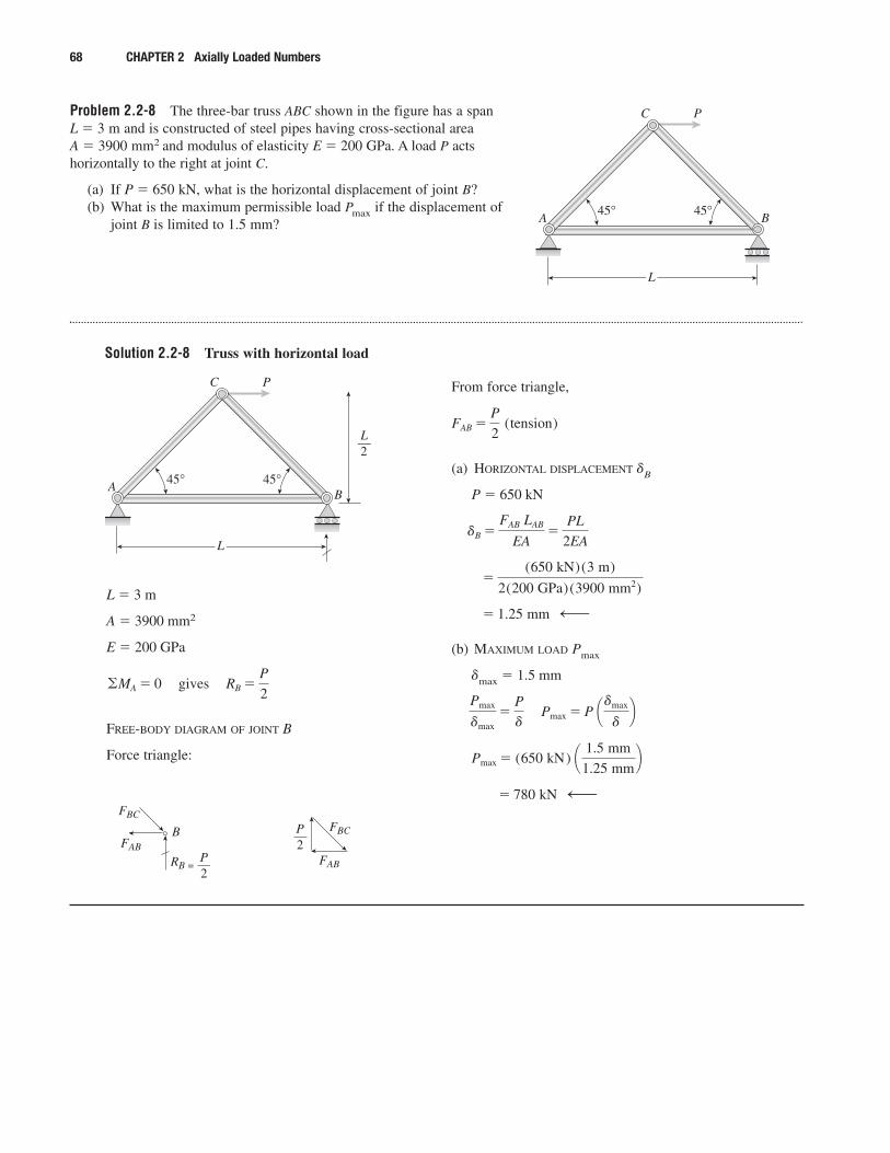
Problem 2.2-8 The three-bar truss ABC shown in the figure has a spanL � 3 m and is constructed of steel pipes having cross-sectional area A � 3900 mm2 and modulus of elasticity E � 200 GPa. A load P actshorizontally to the right at joint C.
(a) If P � 650 kN, what is the horizontal displacement of joint B?(b) What is the maximum permissible load Pmax if the displacement of
joint B is limited to 1.5 mm?
68 CHAPTER 2 Axially Loaded Numbers
L
A B45° 45°
PC
Solution 2.2-8 Truss with horizontal load
L
AB
45° 45°
PC
L2—
P2
FBC
FAB
RB =
B
L � 3 m
A � 3900 mm2
E � 200 GPa
FREE-BODY DIAGRAM OF JOINT B
Force triangle:
©MA � 0�gives�RB �P
2
From force triangle,
(a) HORIZONTAL DISPLACEMENT �B
P � 650 kN
(b) MAXIMUM LOAD Pmax
�max � 1.5 mm
� 780 kN —
Pmax � (650 kN) ¢ 1.5 mm
1.25 mm≤
Pmax
�max�
P
��Pmax � P ¢�max
�≤
� 1.25 mm —
�(650 kN)(3 m)
2(200 GPa)(3900 mm2)
�B �FAB LAB
EA�
PL
2EA
FAB �P
2 (tension)
P2
FBC
FAB
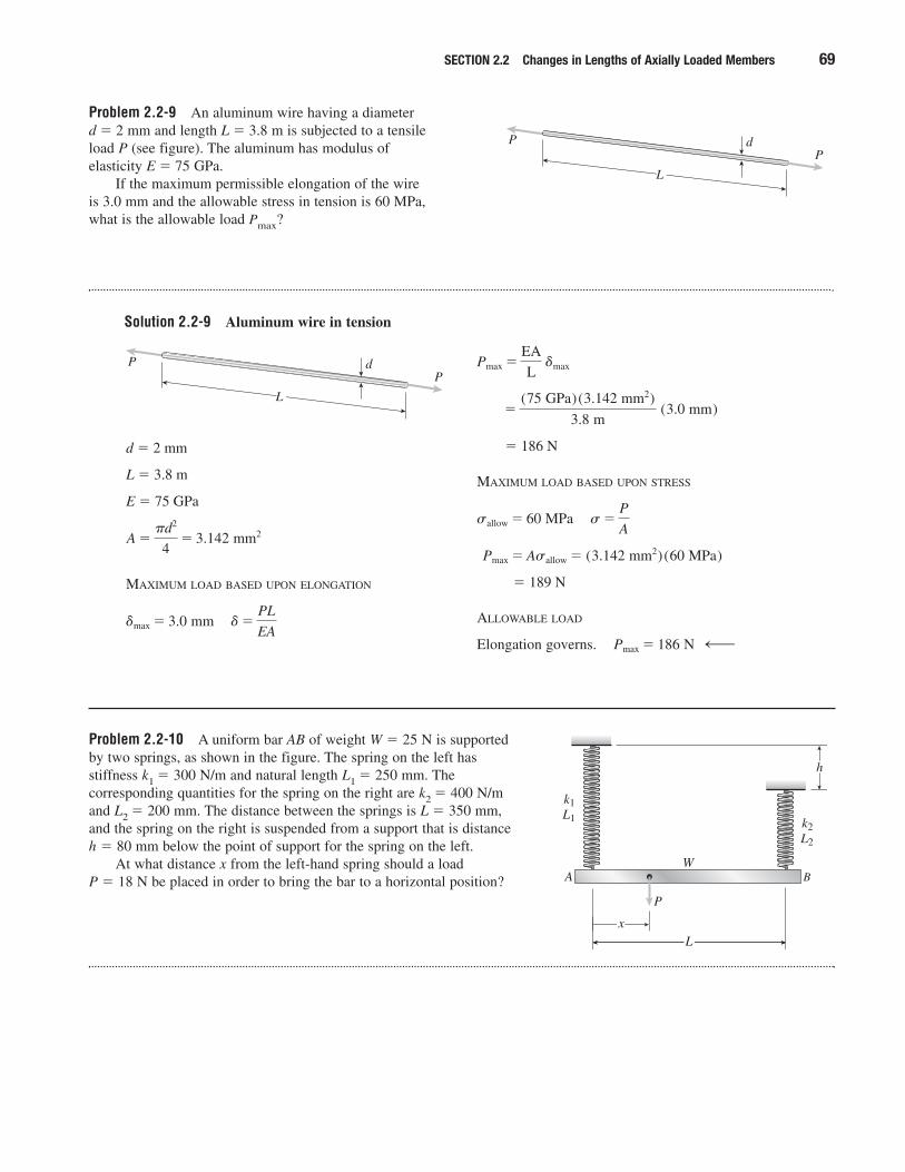
Problem 2.2-9 An aluminum wire having a diameter d � 2 mm and length L � 3.8 m is subjected to a tensileload P (see figure). The aluminum has modulus ofelasticity E � 75 GPa.
If the maximum permissible elongation of the wire is 3.0 mm and the allowable stress in tension is 60 MPa,what is the allowable load Pmax?
SECTION 2.2 Changes in Lengths of Axially Loaded Members 69
PdP
L
Solution 2.2-9 Aluminum wire in tension
PdP
L
d � 2 mm
L � 3.8 m
E � 75 GPa
MAXIMUM LOAD BASED UPON ELONGATION
�max � 3.0 mm�� �PL
EA
A ��d2
4� 3.142 mm2
� 186 N
MAXIMUM LOAD BASED UPON STRESS
� 189 N
ALLOWABLE LOAD
Elongation governs.�Pmax � 186 N —
Pmax � Asallow � (3.142 mm2)(60 MPa)
sallow � 60 MPa�s�P
A
�(75 GPa)(3.142 mm2)
3.8 m (3.0 mm)
Pmax �EA
L �max
Problem 2.2-10 A uniform bar AB of weight W � 25 N is supportedby two springs, as shown in the figure. The spring on the left hasstiffness k1 � 300 N/m and natural length L1 � 250 mm. Thecorresponding quantities for the spring on the right are k2 � 400 N/mand L2 � 200 mm. The distance between the springs is L � 350 mm,and the spring on the right is suspended from a support that is distanceh � 80 mm below the point of support for the spring on the left.
At what distance x from the left-hand spring should a load P � 18 N be placed in order to bring the bar to a horizontal position?
P
W
x
h
L
A
k1L1 k2
L2
B

Solution 2.2-10 Bar supported by two springs
Reference line
70 CHAPTER 2 Axially Loaded Numbers
P
x
A
�1
k1k2
L2
B
W
�2
L1
h
L2—L
2—
W � 25 N
k1 � 300 N/m
k2 � 400 N/m
L � 350 mm
h � 80 mm
P � 18 N
NATURAL LENGTHS OF SPRINGS
L1 � 250 mm L2 � 200 mm
OBJECTIVE
Find distance x for bar AB to be horizontal.
FREE-BODY DIAGRAM OF BAR AB
(Eq. 1)
c� T�
F1 � F2 � P � W � 0 (Eq. 2)
SOLVE EQS. (1) AND (2):
SUBSTITUTE NUMERICAL VALUES:
UNITS: Newtons and meters
ELONGATIONS OF THE SPRINGS
BAR AB REMAINS HORIZONTAL
Points A and B are the same distance below thereference line (see figure above).
or 0.250 � 0.10167 � 0.17143 x� 0.080 � 0.200 � 0.12857 x � 0.031250
SOLVE FOR x:
0.300 x � 0.040420 x � 0.1347 m
x � 135 mm —
∴ L1 � �1 � h � L2 � �2
�2 �F2
k2�
F2
400� 0.12857x � 0.031250
�1 �F1
k1�
F1
300� 0.10167 � 0.17143x
F2 � (18)¢ x
0.350≤� 12.5 � 51.429x � 12.5
F1 � (18)¢1 �x
0.350≤� 12.5 � 30.5 � 51.429x
F1 � P¢1 �x
L≤�
W
2�F2 �
PX
L�
W
2
©Fvert � 0
F2L � PX �WL
2� 0
©MA � 0 � �
P
x
A B
W
F1 F2
L2— L
2—

Problem 2.2-11 A hollow, circular, steel column (E � 30,000 ksi) issubjected to a compressive load P, as shown in the figure. The columnhas length L � 8.0 ft and outside diameter d � 7.5 in. The load P � 85 k.
If the allowable compressive stress is 7000 psi and the allowableshortening of the column is 0.02 in., what is the minimum required wallthickness tmin?
SECTION 2.2 Changes in Lengths of Axially Loaded Members 71
P
d
t
L
Solution 2.2-11 Column in compression
P
d
t
L
P � 85 k
E � 30,000 ksi
L � 8.0 ft
d � 7.5 in.
�allow � 7,000 psi
�allow � 0.02 in.
REQUIRED AREA BASED UPON ALLOWABLE STRESS
s�P
A�A �
Psallow
�85 k
7,000 psi� 12.14 in.2
REQUIRED AREA BASED UPON ALLOWABLE SHORTENING
SHORTENING GOVERNS
Amin � 13.60 in.2
MINIMUM THICKNESS tmin
SUBSTITUTE NUMERICAL VALUES
tmin � 0.63 in. —
tmin �7.5 in.
2�B¢7.5 in.
2≤
2
�13.60 in.2
�
tmin �d
2�B¢d2≤2 �
Amin
�
t �d
2�B¢d2≤2 �
A��or
�Bd 2�4A�
(d � 2t)2 � d 2�4A��or�d � 2t
� � (d � 2t)2
A ��
4[d 2� (d � 2t)2 ]�or�4A
�� d 2
� 13.60 in.2
� �PL
EA�A �
PL
E�allow�
(85 k)(96 in.)
(30,000 ksi)(0.02 in.)

Problem 2.2-12 The horizontal rigid beam ABCD issupported by vertical bars BE and CF and is loaded byvertical forces P1 � 400 kN and P2 � 360 kN acting at points A and D, respectively (see figure). Bars BE and CF aremade of steel (E � 200 GPa) and have cross-sectional areasABE � 11,100 mm2 and ACF � 9,280 mm2. The distancesbetween various points on the bars are shown in the figure.
Determine the vertical displacements �A and �D of pointsA and D, respectively.
72 CHAPTER 2 Axially Loaded Numbers
A
P1 = 400 kN P2 = 360 kN
B C
1.5 m 1.5 m
2.4 m
0.6 m
2.1 m
D
F
E
Solution 2.2-12 Rigid beam supported by vertical bars
A
P1 = 400 kN P2 = 360 kN
B C
1.5 m 1.5 m
2.4 m
0.6 m
2.1 m
D
F
E
ABE � 11,100 mm2
ACF � 9,280 mm2
E � 200 GPa
LBE � 3.0 m
LCF � 2.4 m
P1 � 400 kN; P2 � 360 kN
FREE-BODY DIAGRAM OF BAR ABCD
SHORTENING OF BAR BE
SHORTENING OF BAR CF
DISPLACEMENT DIAGRAM
� 0.600 mm
�CF �FCF LCF
EACF
�(464 kN)(2.4 m)
(200 GPa)(9,280 mm2)
� 0.400 mm
�BE �FBE LBE
EABE
�(296 kN)(3.0 m)
(200 GPa)(11,100 mm2)
A
P1 = 400 kN FBE FCF P2 = 360 kN
B C
1.5 m 1.5 m 2.1 mD
(400 kN)(1.5 m) � FCF(1.5 m) � (360 kN)(3.6 m) � 0
FCF � 464 kN
(400 kN)(3.0 m) � FBE(1.5 m) � (360 kN)(2.1 m) � 0
FBE � 296 kN
©MC � 0 � �
©MB � 0 ��
A B C1.5 m 1.5 m 2.1 m D
�A�BE
�CF
�D
�BE � �A � �CF � �BE or �A � 2�BE � �CF
(Downward)
(Downward)
� 0.880 mm —
�12
5(0.600 mm) �
7
5(0.400 mm)
or��D �12
5 �CF �
7
5 �BE
�D � �CF �2.1
1.5(�CF � �BE)
� 0.200 mm —
�A � 2(0.400 mm) � 0.600 m

Problem 2.2-13 A framework ABC consists of two rigidbars AB and BC, each having length b (see the first part ofthe figure). The bars have pin connections at A, B, and Cand are joined by a spring of stiffness k. The spring isattached at the midpoints of the bars. The framework has apin support at A and a roller support at C, and the bars areat an angle � to the hoizontal.
When a vertical load P is applied at joint B (see thesecond part of the figure) the roller support C moves to the right, the spring is stretched, and the angle of the barsdecreases from � to the angle �.
Determine the angle � and the increase � in thedistance between points A and C. (Use the following data;b � 8.0 in., k � 16 lb/in., � � 45°, and P � 10 lb.)
SECTION 2.2 Changes in Lengths of Axially Loaded Members 73
� �
k
A C
B
b2—
b2—
b2—
b2—
A C
B
��
P
Solution 2.2-13 Framework with rigid bars and a spring
� �
k
A C
B
b2—
b2—
b2—
b2—
L1
A C
B
��
P
L2
C
B
�
P
P2—
F
L2 2—
F
h2— P
2—
h2—
h
WITH NO LOAD
L1 � span from A to C
� 2b cos �
S1 � length of spring
�L1
2� b cos �
WITH LOAD P
L2 � span from A to C
� 2b cos �
S2 � length of spring
FREE-BODY DIAGRAM OF BC
�L2
2� b cos u
h � height from C to B � b sin �
F � force in spring due to load P
or P cos � � F sin � (Eq. 1)P
2 ¢L2
2≤� F ¢h
2≤� 0
©MB � 0 � �
L2
2� b cos u
Probs. 2.1-13 and 2.2-14

74 CHAPTER 2 Axially Loaded Numbers
DETERMINE THE ANGLE �
�S � elongation of spring
� S2 � S1 � b(cos � � cos �)
For the spring: F � k(�S )
F � bk(cos � � cos �)
Substitute F into Eq. (1):
P cos � � bk(cos � � cos �)(sin �)
(Eq. 2)
This equation must be solved numerically for theangle �.
DETERMINE THE DISTANCE �
� � L2 � L1 � 2b cos � � 2b cos �
� 2b(cos � � cos �)
or�P
bk cot u� cos u� cos � � 0 —
From Eq. (2):
Therefore,
(Eq. 3)
NUMERICAL RESULTS
b � 8.0 in. k � 16 lb/in. � � 45� P � 10 lb
Substitute into Eq. (2):
0.078125 cot � � cos � � 0.707107 � 0 (Eq. 4)
Solve Eq. (4) numerically:
Substitute into Eq. (3):
� � 1.78 in. —
u� 35.1� —
�2P
b cot u� —
� � 2b ¢cos u� cos u�P cot u
bk≤
cos � � cos u�P cot u
bk
Problem 2.2-14 Solve the preceding problem for the following data:b � 200 mm, k � 3.2 kN/m, � � 45°, and P � 50 N.
Solution 2.2-14 Framework with rigid bars and a spring
See the solution to the preceding problem.
EQ. (2):
EQ. (3): � �2P
k cot u
P
bk cot u� cos u� cos � � 0
NUMERICAL RESULTS
b � 200 mm k � 3.2 kN/m � � 45� P � 50 N
Substitute into Eq. (2):
0.078125 cot � � cos � � 0.707107 � 0 (Eq. 4)
Solve Eq. (4) numerically:
Substitute into Eq. (3):
� � 44.5 mm —
u� 35.1� —

Changes in Lengths Under Nonuniform Conditions
Problem 2.3-1 Calculate the elongation of a copper bar of solid circular cross section with tapered ends when it isstretched by axial loads of magnitude 3.0 k (see figure).
The length of the end segments is 20 in. and the length of the prismatic middle segment is 50 in. Also, the diameters at cross sections A, B, C, and D are 0.5, 1.0, 1.0, and 0.5 in.,respectively, and the modulus of elasticity is 18,000 ksi.(Hint: Use the result of Example 2-4.)
SECTION 2.3 Changes in Lengths under Nonuniform Conditions 75
A BC
D
3.0 k20 in.
20 in.3.0 k
50 in.
Solution 2.3-1 Bar with tapered ends
A BC
D
3.0 k20 in.
20 in.3.0 k
50 in.
dA � dD � 0.5 in. P � 3.0 k
dB � dC � 1.0 in. E � 18,000 ksi
END SEGMENT (L � 20 in.)
From Example 2-4:
� 0.008488 in.�1 �4(3.0 k)(20 in.)
�(18,000 ksi)(0.5 in.) (1.0 in.)
� �4PL
�E dA dB
MIDDLE SEGMENT (L � 50 in.)
ELONGATION OF BAR
� 2(0.008488 in.) � (0.01061 in.)
� 0.0276 in. —
� � a NL
EA� 2�1 � �2
� 0.01061in.
�2 �PL
EA�
(3.0 k)(50 in.)
(18,000 ksi)(�4 ) (1.0 in.)2
Problem 2.3-2 A long, rectangular copper bar under a tensile load Phangs from a pin that is supported by two steel posts (see figure). Thecopper bar has a length of 2.0 m, a cross-sectional area of 4800 mm2, and a modulus of elasticity Ec � 120 GPa. Each steel post has a height of 0.5 m, a cross-sectional area of 4500 mm2, and a modulus of elasticityEs � 200 GPa.
(a) Determine the downward displacement � of the lower end of thecopper bar due to a load P � 180 kN.
(b) What is the maximum permissible load Pmax if the displacement � is limited to 1.0 mm?
P
Steelpost
Copperbar

Solution 2.3-2 Copper bar with a tensile load
76 CHAPTER 2 Axially Loaded Numbers
LS
LC
P
Steelpost
Copperbar
Lc � 2.0 m
Ac � 4800 mm2
Ec � 120 GPa
Ls � 0.5 m
As � 4500 mm2
Es � 200 GPa
(a) DOWNWARD DISPLACEMENT � (P � 180 kN)
(b) MAXIMUM LOAD Pmax (�max � 1.0 mm)
Pmax � (180 kN) ¢ 1.0 mm
0.675 mm≤ � 267 kN —
Pmax
P�
�max
��Pmax � P ¢�max
�≤
� 0.675 mm —
� � �c � �s � 0.625 mm � 0.050 mm
� 0.050 mm
�s �(P�2)Ls
Es As
�(90 kN)(0.5 m)
(200 GPa)(4500 mm2)
� 0.625 mm
�c �PLc
Ec Ac
�(180 kN)(2.0 m)
(120 GPa)(4800 mm2)
Problem 2.3-3 A steel bar AD (see figure) has a cross-sectional area of 0.40 in.2 and is loaded by forces P1 � 2700 lb, P2 � 1800 lb, and P3 � 1300 lb. The lengths of the segments of the bar are a � 60 in., b � 24 in., and c � 36 in.
(a) Assuming that the modulus of elasticity E � 30 � 106 psi, calculate the change in length � of the bar. Does the bar elongateor shorten?
(b) By what amount P should the load P3 be increased so that the bar does not change in length when the three loads are applied?
a b c
B
P1 P2P3
A C D
Solution 2.3-3 Steel bar loaded by three forces
B
P1 P2 P3
A C D
60 in. 24 in. 36 in.
A � 0.40 in.2 P1 � 2700 lb P2 � 1800 lb
P3 � 1300 lb E � 30 � 106 psi
AXIAL FORCES (t � tension)
NAB � P1 � P2 � P3 � 3200 lb
NBC � P2 � P3 � 500 lb
NCD � �P3 � �1300 lb
(a) CHANGE IN LENGTH
� 0.0131 in. (elongation) —� (1300 lb)(36 in.)]� (500 lb)(24 in.)
�1
(30 � 106 psi) (0.40 in.2)
[(3200 lb)(60 in.)
�1
EA (NABLAB � NBCLBC � NCDLCD)
� � a NiLi
EiAi

Problem 2.3-4 A rectangular bar of length L has a slot inthe middle half of its length (see figure). The bar has widthb, thickness t, and modulus of elasticity E. The slot haswidth b/4.
(a) Obtain a formula for the elongation � of the bar dueto the axial loads P.
(b) Calculate the elongation of the bar if the material ishigh-strength steel, the axial stress in the middleregion is 160 MPa, the length is 750 mm, and themodulus of elasticity is 210 GPa.
SECTION 2.3 Changes in Lengths under Nonuniform Conditions 77
(b) INCREASE IN P3 FOR NO CHANGE IN LENGTH
P � increase in force P3
The force P must produce a shortening equal to 0.0131 in.in order to have no change in length.
P � 1310 lb —
�P(120 in.)
(30 � 106 psi) (0.40 in.2)
∴ 0.0131 in. � � �PL
EA
b4—
L4—
L4—
L2—
b t
P
P
Solution 2.3-4 Bar with a slot
b4—
b PP
L2—L
4— L
4—
t � thickness L � length of bar
(a) ELONGATION OF BAR
�PL
Ebt ¢1
4�
4
6�
1
4≤�
7PL
6Ebt—
� � a NiLi
EAi
�P(L�4)
E(bt)�
P(L�2)
E(34bt)
�P(L�4)
E(bt)
STRESS IN MIDDLE REGION
Substitute into the equation for �:
(b) SUBSTITUTE NUMERICAL VALUES:
� �7(160 MPa)(750 mm)
8 (210 GPa)� 0.500 mm —
s� 160 MPa�L � 750 mm�E � 210 GPa
�7sL
8E
� �7PL
6Ebt�
7L
6E ¢ P
bt≤�
7L
6E ¢3s
4≤
s�P
A�
P
(34bt)
�4P
3 bt�or
P
bt�
3s
4
P
120 in.

78 CHAPTER 2 Axially Loaded Numbers
b4—
b PP
L2—L
4— L
4—
t � thickness L � length of bar
(a) ELONGATION OF BAR
� PL
Ebt¢14
�4
6�
1
4≤�
7PL
6Ebt —
� � a NiLi
EAi
�P(L�4)
E(bt)�
P(L�2)
E (34 bt)
�P(L�4)
E(bt)
STRESS IN MIDDLE REGION
SUBSTITUTE INTO THE EQUATION FOR �:
(b) SUBSTITUTE NUMERICAL VALUES:
� �7(24,000 psi)(30 in.)
8(30 � 106 psi)
� 0.0210 in. —
E � 30 � 106 psi
s� 24,000 psi�L � 30 in.
�7sL
8E
� �7PL
6Ebt�
7L
6E ¢ P
bt≤�
7L
6E ¢3s
4≤
s�P
A�
P
(34 bt)
�4P
3bt�or�
P
bt�
3s
4
Problem 2.3-6 A two-story building has steel columns AB in the firstfloor and BC in the second floor, as shown in the figure. The roof load P1equals 400 kN and the second-floor load P2 equals 720 kN. Each columnhas length L � 3.75 m. The cross-sectional areas of the first- and second-floor columns are 11,000 mm2 and 3,900 mm2, respectively.
(a) Assuming that E � 206 GPa, determine the total shortening �ACof the two columns due to the combined action of the loads P1and P2.
(b) How much additional load P0 can be placed at the top of thecolumn (point C) if the total shortening �AC is not to exceed 4.0 mm?
P1 = 400 kN
P2 = 720 kNB
A
C
L = 3.75 m
L = 3.75 m
Solution 2.3-6 Steel columns in a building
P1 = 400 kN
P2 = 720 kNB
A
C
L
L
L � length of each column
� 3.75 m
E � 206 GPa
AAB � 11,000 mm2
ABC � 3,900 mm2
(a) SHORTENING �AC OF THE TWO COLUMNS
�AC � 3.72 mm —
� 1.8535 mm � 1.8671 mm � 3.7206 mm
�(400 kN)(3.75 m)
(206 GPa)(3,900 mm2)
� (1120 kN)(3.75 m)
(206 GPa)(11,000 mm2)�
�AC � a Ni Li
Ei Ai
�NAB L
EAAB
�NBC L
EABC
Problem 2.3-5 Solve the preceding problem if the axial stress in themiddle region is 24,000 psi, the length is 30 in., and the modulus ofelasticity is 30 � 106 psi.
Solution 2.3-5 Bar with a slot

Problem 2.3-7 A steel bar 8.0 ft long has a circular cross section of diameter d1 � 0.75 in. over one-half of its length and diameter d2 � 0.5 in. over the other half (see figure). The modulus of elasticity E � 30 � 106 psi.
(a) How much will the bar elongate under a tensile load P � 5000 lb?
(b) If the same volume of material is made into a bar of constant diameter d and length 8.0 ft, what will be the elongation under the same load P?
SECTION 2.3 Changes in Lengths under Nonuniform Conditions 79
(b) ADDITIONAL LOAD P0 AT POINT C
(�AC)max � 4.0 mm
�0 � additional shortening of the two columnsdue to the load P0
�0 � (�AC)max � �AC � 4.0 mm � 3.7206 mm
� 0.2794 mm
Also, �0 �P0 L
EAAB
�P0 L
EABC
�P0 L
E¢ 1
AAB
�1
ABC
≤
Solve for P0:
SUBSTITUTE NUMERICAL VALUES:
P0 � 44,200 N � 44.2 kN —
ABC � 3,900 � 10�6 m2
L � 3.75 m� AAB � 11,000 � 10�6 m2
�0 � 0.2794 � 10�3 mE � 206 � 109
N�m2
P0 �E�0
L ¢ AAB ABC
AAB � ABC
≤
d1 = 0.75 in.
P
d2 = 0.50 in.
4.0 ft 4.0 ft
P = 5000 lb
Solution 2.3-7 Bar in tension
d1 = 0.75 in.
P
d2 = 0.50 in.
4.0 ft 4.0 ft
P = 5000 lb
P � 5000 lb
E � 30 � 106 psi
L � 4 ft � 48 in.
(a) ELONGATION OF NONPRISMATIC BAR
� 0.0589 in. —
� B 1�4 (0.75 in)2 �
1�4 (0.50 in.)2 R
� �(5000 lb)(48 in.)
30 � 106 psi
� � a Ni Li
Ei Ai
�PL
E a1
Ai
(B) ELONGATION OF PRISMATIC BAR OF SAME VOLUME
Original bar: Vo � A1L � A2L � L(A1 � A2)
Prismatic bar: Vp � Ap(2L)
Equate volumes and solve for Ap:
Vo � Vp L(A1 � A2) � Ap(2L)
NOTE: A prismatic bar of the same volume willalways have a smaller change in length than will anonprismatic bar, provided the constant axial loadP, modulus E, and total length L are the same.
� 0.0501 in. —
� �P(2L)
EAp
�(5000 lb)(2)(48 in.)
(30 � 106 psi) (0.3191 in.2)
� �
8[ (0.75 in.)2 � (0.50 in.)2 ] � 0.3191 in.2
Ap �A1 � A2
2�
1
2 ¢�
4≤ (d1
2 � d22)