
0199912100k.pdf
25
AutoSwitchable, 4 Nucleus, and ATB NMR Probes Varian, Inc. NMR Systems Pub. No. 01-999121-00, Rev. K 0606
-
Upload
oscar-frizzi -
Category
Documents
-
view
53 -
download
1
description
ASW ATB probe
Transcript of 0199912100k.pdf

AutoSwitchable,4 Nucleus, and
ATB NMR ProbesVarian, Inc. NMR SystemsPub. No. 01-999121-00, Rev. K 0606

01-999121-00 K 0606 AutoSwitchable, 4 Nucleus, and ATB NMR Probes Installation 1
AutoSwitchable, 4 Nucleus, and ATB NMR ProbesVarian, Inc. NMR Systems
• Overview, page 2
• Safety Precautions, page 3
• Inserting the Probe, page 3
• Connecting the PFG and Temperature Cables, page 3
• Connecting and Adjusting the Air and Nitrogen, page 3
• Connecting the Probe, page 3
• Tuning Controls, page 4
• Tuning Characteristics, page 5
• Tuning Ranges, page 6
• Using Capacitor Sticks, page 7
• Tuning X-CHANNEL from Unknown to 4-Nuc Mode, page 7
• Tuning the Low-Band Channel, page 8
• Tuning Summary for 4-Nucleus to Switchable, page 11
• AutoSwitchable Tuning Charts, page 11
• Calibrating and Testing Probes, page 13
• Probe Test Results, page 21
Pub. No. 01-999121-00, Rev. K 0606

AutoSwitchable, 4 Nucleus, and ATB NMR Probes
2 AutoSwitchable, 4 Nucleus, and ATB NMR Probes Installation 01-999121-00 K 0606
OverviewAutoSwitchable probes and 4 Nucleus probes are (listed in Table 1) combine simplified 4-nucleus operation with the versatility of multinuclear broadband nuclear observation.
ATB (Automation Triple Resonance Broadband) probes (listed in Table 2) support a wide possible array of liquids NMR techniques in an automation environment where performance is critical. The inner coil of this probe is broadband tunable and is constructed with circuitry to completely eliminate the need to tune this coil on a sample to sample basis. The outer coil is simultaneously tuned to 19F and 1H making X-{1H, 19F} indirect detection experiments and 1H or 19F direct observe NMR experiments convenient.
Table 1. AutoSwitchable and 4 Nucleus Probes
Magnet (MHz)
Bore (mm)
Sample (mm)
Range Probe Part No.
200 54 5 1H/19F/13C/31P 01-910569-00
200 89 5 1H/19F/13C/31P 01-910570-00
200 PFG 54 5 1H/19F/13C/31P 01-907876-00
200 PFG 89 5 1H/19F/13C/31P 01-907875-00
300 54 5 1H/19F/13C/31P 01-910572-00
300 89 5 1H/19F/13C/31P 01-910573-00
300 PFG 54 5 1H/19F/13C/31P 01-910575-00
300 PFG 89 5 1H/19F/13C/31P 01-91197-00
300 54 5 1H/19F/13C/31P, 1H/19F/{15N–31P} 01-903109-05
300 PFG 54 5 1H/19F/13C/31P, 1H/19F/{15N–31P} 01-904083-05
300 89 5 1H/19F/13C/31P, 1H/19F/{15N–31P} 01-903110-05
300 PFG 89 5 1H/19F/13C/31P, 1H/19F/{15N–31P} 01-904084-05
400 54 5 1H/19F/13C/31P 01-910550-00
400 89 5 1H/19F/13C/31P 01-910581-00
400 PFG 54 5 1H/19F/13C/31P 01-910583-00
400 PFG 54 5 1H/19F/13C/31P, 1H/19F/{15N–31P} 01-904089-06
400 PFG 89 5 1H/19F/13C/31P, 1H/19F/{15N–31P} 01-904090-06
400 54 5 1H/19F/13C/31P, 1H/19F/{15N–31P} 01-910585-00
400 89 5 1H/19F/13C/31P, 1H/19F/{15N–31P} 01-910586-00
Table 2. Automation Triple Resonance Broadband Probes
Magnet (MHz)
Bore (mm)
Sample (mm)
Range Probe Part No.
300 ATB PFG 54 5 1H/19F/{15N–31P} 01-907194-01
300 ATB PFG 89 5 1H/19F/{15N–31P} 01-907193-01
400 ATB PFG 54 5 1H/19F/{15N–31P} 01-908036-00
400 ATB PFG 89 5 1H/19F/{15N–31P} 01-908037-00

01-999121-00 K 0606 AutoSwitchable, 4 Nucleus, and ATB NMR Probes Installation 3
Safety Precautions
Safety Precautions
CAUTION: Tighten a capacitor stick to finger-tight. Overtightening can damage the probe.
CAUTION: Do not attempt to tune the AutoSwitchable, 4 Nucleus, or ATB probe before thoroughly reading the instructions in this manual. Any slight altering of the tuning on the AutoSwitchable can completely throw off the delicate balance between the two nuclei resonant on a port.
Inserting the Probe1. Make sure the upper barrel and probe mounting flange are installed and adjusted for
the probe.
2. Insert the probe into the bottom of the magnet dewar.
3. Secure the probe with the thumbscrews attached.
Connecting the PFG and Temperature Cables1. Connect the cable from the variable temperature (VT) controller to the 9-pin
connector (VT Control) on the probe.
2. PFG probes only — connect the system PFG cable from the NMR console to the PFG connector on the probe base.
Connecting and Adjusting the Air and Nitrogen1. Connect the VT nitrogen gas hose to the stub tee on the glass dewar projecting to the
side at the base of the probe.
2. Connect the body-cooling air hose to the hose barb protruding from the side of the probe. Adjust the air flow:
• Temperatures between –20°C and +80°C, use an air flow of 10 to 15 LPM.
• Temperatures below –20°C and above +80°C, increase the air flow.
Connecting the Probe1. Connect the high-band (1H/19F):
a. Connect the appropriate filter (high-pass) to the highband preamplifier.
b. Connect the highband cable between the filter and the 1H/19F connector on the probe.
2. Connect the low-band:

AutoSwitchable, 4 Nucleus, and ATB NMR Probes
4 AutoSwitchable, 4 Nucleus, and ATB NMR Probes Installation 01-999121-00 K 0606
a. Connect the appropriate filters (low-pass and lock reject) to the lowband preamplifier.
b. Connect the lowband cable between the filter and the OBS connector on the probe.
3. Connect the lock:
a. Connect a notch filter (2H bandpass notch) to the lock preamplifier.
b. Connect the lock cable between the filter and the LOCK connector on the probe.
Tuning ControlsThe tuning controls for the AutoSwitchable and ATB probes extend from the bottom of the probe base. Shown in Figure 1 is the base of the AutoSwitchable. The base of the ATB is similar.
AutoSwitchable Probes
The tuning controls of this probe are operated with the coaxial, brass-colored tuning knobs. Both the high-band channel (labeled 1H/19F in red) and the low-band channel (labeled X-CHANNEL in green) are tuned by independent controls that control two resonances for each channel.
The match function is controlled by the smooth knob on the bottom. The knurled knob controls two tune functions:
• DOWN position — the word DOWN is visible and the gear system for the counter is engaged (for X-channel tuning),
• UP position — with the word UP is visible and the gear system engaged.
Figure 1. AutoSwitchable PFG Probe Tuning Controls And Connectors
PFG connector
High-band tuning controls(shown in UP positions)Low-Band tuning controls
(shown in DOWN position)
Guide bore for 1/4-waveand capacitor sticks(shown with 1/4-wave stick)
Tuning counter
Counter label
Low-bandmatch
High-bandmatch

01-999121-00 K 0606 AutoSwitchable, 4 Nucleus, and ATB NMR Probes Installation 5
Tuning Characteristics
ATB Probes
Tuning the 1H/19F channel
This probe tunes much like the AutoSwitchable probe for 1H/19F tuning. Follow the instructions appropriate for the system:
Tuning the X channel
• The X-Channel tuning knob on the Automation Triple Resonance Broadband probe does not have an UP and DOWN position.
• X-Channel tuning procedures for the ATB probe are the same as the Autoswitchable when it is operated with the X-channel tuned to a single nucleus. This procedure is provided in Tuning the Low-Band Channel, page 8.
The next sections describe the tuning characteristics of the tune control.
Tuning Characteristics
High-Band
Figure 2 shows the tuning characteristics of the high-band tune controls for AutoSwitchable, 4 Nucleus, and ATB probes. Both resonances are moved simultaneously with the knob in the DOWN position. Clockwise rotation of the knob increases the frequency. The 1H resonance is moved with the knob in the UP position. Clockwise rotation of the knob increases the separation and the resonance frequency.
Low-Band 4-Nucleus Mode (AutoSwitchable and 4 Nucleus only)
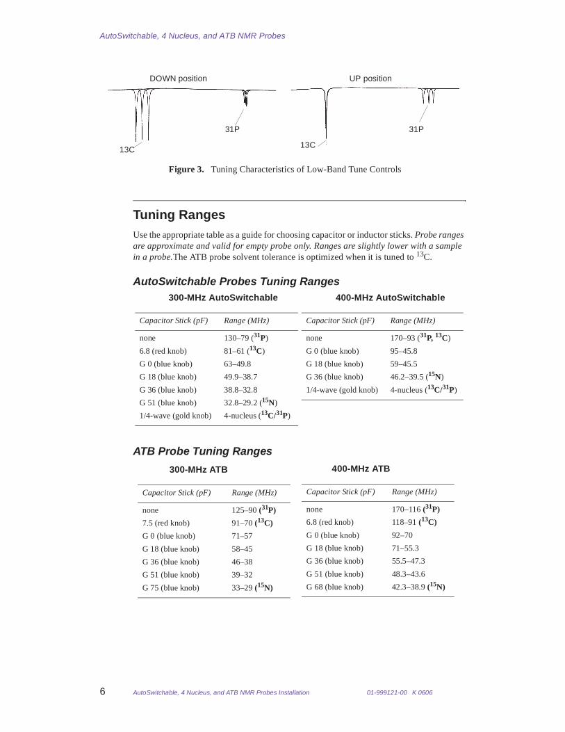
Figure 3 shows the tuning characteristics of the low-band tune controls. This applies only to the AutoSwichable and 4 Nucleus probes. Mainly the lower resonance frequency (13C) is changed in the DOWN position. Clockwise rotation of the knob increases the resonance frequency. Mainly the upper resonance frequency (31P) is changed in the UP position. Clockwise rotation of the knob increases resonance frequency.
19F 19F 1H1H
Figure 2. Tuning Characteristics of High-Band Tune Controls
DOWN position UP position
AutoSwitchable, 4 Nucleus, and ATB NMR Probes
6 AutoSwitchable, 4 Nucleus, and ATB NMR Probes Installation 01-999121-00 K 0606
Tuning Ranges Use the appropriate table as a guide for choosing capacitor or inductor sticks. Probe ranges are approximate and valid for empty probe only. Ranges are slightly lower with a sample in a probe.The ATB probe solvent tolerance is optimized when it is tuned to 13C.
AutoSwitchable Probes Tuning Ranges
ATB Probe Tuning Ranges
13C
31P
13C
31P
Figure 3. Tuning Characteristics of Low-Band Tune Controls
DOWN position UP position
300-MHz AutoSwitchable
Capacitor Stick (pF) Range (MHz)
none 130–79 (31P)
6.8 (red knob) 81–61 (13C)
G 0 (blue knob) 63–49.8
G 18 (blue knob) 49.9–38.7
G 36 (blue knob) 38.8–32.8
G 51 (blue knob) 32.8–29.2 (15N)
1/4-wave (gold knob) 4-nucleus (13C/31P)
400-MHz AutoSwitchable
Capacitor Stick (pF) Range (MHz)
none 170–93 (31P, 13C)
G 0 (blue knob) 95–45.8
G 18 (blue knob) 59–45.5
G 36 (blue knob) 46.2–39.5 (15N)
1/4-wave (gold knob) 4-nucleus (13C/31P)
300-MHz ATB
Capacitor Stick (pF) Range (MHz)
none 125–90 (31P)
7.5 (red knob) 91–70 (13C)
G 0 (blue knob) 71–57
G 18 (blue knob) 58–45
G 36 (blue knob) 46–38
G 51 (blue knob) 39–32
G 75 (blue knob) 33–29 (15N)
400-MHz ATB
Capacitor Stick (pF) Range (MHz)
none 170–116 (31P)
6.8 (red knob) 118–91 (13C)
G 0 (blue knob) 92–70
G 18 (blue knob) 71–55.3
G 36 (blue knob) 55.5–47.3
G 51 (blue knob) 48.3–43.6
G 68 (blue knob) 42.3–38.9 (15N)

01-999121-00 K 0606 AutoSwitchable, 4 Nucleus, and ATB NMR Probes Installation 7
Using Capacitor Sticks
Using Capacitor SticksCapacitor sticks extend the tuning range of the probe. Refer to the tables in Tuning Ranges, page 6 as a guide for choosing a stick.
CAUTION: Tighten a capacitor stick to finger-tight. Overtightening can damage the probe.
1. Remove the capacitor stick from the protective shipping container.
The stick value is labeled at the bottom end of the stick and color coded for easy identification:
• Red knobs – regular capacitor sticks (not required for all probes)
• Blue knobs – grounded capacitor sticks
• Gold knobs – 1/4-wavelength sticks (not used on ATB probes)
The top of the stick has a flat region that serves as a key for proper orientation of the capacitor stick in the probe.
2. Insert the stick into the probe bottom until the tip of the stick hit a barrier.
3. Hold the plastic stick end (not the colored knob) and slightly rotate the stick until the key engage and the stick move inward slightly.
4. Continue inserting the stick the rest of the way. Use finger tight. Do not overtighten.
5. When the threads of the stick knob touch the bottom of the probe, twist the knob to affix the stick to the probe.
Tuning X-CHANNEL from Unknown to 4-Nuc ModeTune the X channel from an unknown tuning state by focus on 13C while adjusting the match. This section applies only to Autoswitchable probes.
1. Make sure that the 1/4-wavelength cable is installed and the correct sample is inserted. Then set the counter (DOWN position) to the factory setting of 4 NUC (see counter label on the probe).
2. Set the console to 13C, and turn only the match knob to minimize the reflection reading. The match capacitor should be only a few turns from minimum, turn it counterclockwise until it hits the stop; then, turn it about 5 turns clockwise again.
3. Set the console to 31P, turn only the UP position to get the reflection minimum; then, switch back to 13C and turn only the match to minimize 13C.
4. Set the console to 31P and turn only the UP position to get the reflection minimum. This gets close enough to both frequencies to get started.
5. Change back to 13C, turn the DOWN position and match to optimize the reflection. The counter should remain fairly close to the factory-set value.
6. Switch to 31P and turn only the UP position to minimize the reflection.
7. Repeat steps 5 and 6 once.
8. Add about a quarter-turn clockwise to match. Turn only the DOWN position to minimize 13C; turn only the UP position to minimize 31P. Do not adjust match anymore. The meter readout should be much better on 13C than on 31P.

AutoSwitchable, 4 Nucleus, and ATB NMR Probes
8 AutoSwitchable, 4 Nucleus, and ATB NMR Probes Installation 01-999121-00 K 0606
Tuning the Low-Band ChannelThe AutoSwitchable probe is similar in operation to the ATB probe or other switchable probe in switchable mode. This procedure does not apply to 4 -nucleus probes. The high-band port is simultaneously tuned to 1H and 19F, while the low-band port is tunable from 15N to 31P. Use the correct 1/4-wavelength cable and the standard filters (the 1H high-pass for the 1H/19F channel and the lock-reject and low-pass filter for the 13C/31P/X channel).
Refer to the following sections for tuning procedures:
• Tuning 300- and 400-MHz Probes to 31P, 13C, or 15N, this page
• Tuning 300-MHz AutoSwitchable Probe to 63–130 MHz or the ATB Probe to 70–125 MHz, page 9
• Tuning 300-MHz AutoSwitchable Probe to 30–63 MHz or the ATB Probe to 29–71 MHz, page 9
• Tuning 400-MHz AutoSwitchable Probe to 94–170 MHz or the ATB Probe to 116–170 MHz, page 10
• Tuning 400-MHz AutoSwitchable Probe to 39–94 MHz or the ATB Probe to 38.9–118 MHz, page 10
Tuning 300- and 400-MHz Probes to 31P, 13C, or 15N
Tune 300- and 400-MHz AutoSwitchable or ATB probes to 31P, 13C, or 15N as follows:
1. Set the spectrometer to observe the desired nucleus.
2. Insert the standard sample into the probe and tune as follows:
• 31P nucleus – Use no capacitor stick for either the AutoSwitchable or ATB probe. Preset the down tuner to the factory counter value.
AutoSwitchable probe only — use the UP position and match to find the reflection minimum. Match should be only a few turns from minimum (fully counterclockwise), preset match first, then use the UP position to find the resonance. Iteratively twist the UP position and match for optimum reflection. There is no UP or DOWN position for the ATB probe.
• 13C nucleus
Preset counter to factory value.
• AutoSwitchable probe only — leave match close to the 4-nucleus or 31P setting, use UP position to find resonance. Use UP position and match to optimize.There is no UP or DOWN position for the ATB probe.
• 300-MHz probes
AutoSwitchable — use the 6.8 pF capacitor stick (red knob).
ATB–use the 7.5 pF capacitor stick.
• 400-MHz probes
AutoSwitchable — use no capacitor stick.
ATB–use the 6.8 pF capacitor stick (red knob)
• 15N nucleus
AutoSwitchable probe only— note that the UP position tuner has no effect with capacitor sticks with the blue knob (G-type), leave it in 4-nucleus position for

01-999121-00 K 0606 AutoSwitchable, 4 Nucleus, and ATB NMR Probes Installation 9
Tuning the Low-Band Channel
easier return. Preset the counter to factory value, add match (clockwise) to find resonance, use DOWN position and match to optimize.
• 300-MHz probes
AutoSwitchable—use the G 51pF capacitor stick (blue knob)
ATB–use the G 75pF capacitor stick (blue knob)
• 400-MHz probes
AutoSwitchable—use the G 36pF capacitor stick (blue knob)
ATB—use the G 68pF capacitor stick (blue knob)
3. Return cables to the same position as connected prior to tuning.
Tuning 300-MHz AutoSwitchable Probe to 63–130 MHz or the ATB Probe to 70–125 MHz
The following steps tune a 300-MHz AutoSwitchable probe to nuclei in the frequency range of 63–130 MHz or ATB probe to nuclei in the frequency range of 70–125 MHz.
1. Choose the appropriate capacitor stick:
• AutoSwitchable Probe:
79–130 MHz, no stick
63–79 MHz, 6.8 pF stick
• ATB probe:
90–125 MHz, no stick
70–91 MHx 7.5 pF stick
2. Preset the Broadband match knob to fully counterclockwise and then turn it several turns clockwise.
3. Preset the counter by turning the Broadband tune knob.
AutoSwitchable probe only — engage the DOWN position and turn the tune knob to a value appropriate for the nucleus of interest.
Find an approximate value by interpolating between 0 and the setting for 31P for frequencies above 79 MHz or interpolating between 0 and 80 for frequencies in the range of 63–79 MHz.
4. Turn the Broadband tune knob (the UP position for tuning an AutoSwitchable probe) and the match knob to find the reflection minimum.
5. Repeat with the tune knob (the UP position for tuning an AutoSwitchable probe) and the match knob to minimize the reflection meter reading.
6. Record the counter reading for future reference.
Tuning 300-MHz AutoSwitchable Probe to 30–63 MHz or the ATB Probe to 29–71 MHz
The following steps tune a 300-MHz AutoSwitchable probe to nuclei in the frequency range of 30–63 MHz.
1. Select the appropriate capacitor stick, refer to the tables in Tuning Ranges, page 6.
2. Turn the Broadband tune knob (the DOWN position for tuning an AutoSwitchable probe) position to find the resonance. If the probe has been operated at this frequency before, refer to the notes made at that time for the appropriate counter setting.

AutoSwitchable, 4 Nucleus, and ATB NMR Probes
10 AutoSwitchable, 4 Nucleus, and ATB NMR Probes Installation 01-999121-00 K 0606
AutoSwitchable probe only — the UP position of the tune knob has no effect with grounded capacitor sticks (blue knob). Leave the knob in the 4-nuc position for easier return to 4-nucleus operation.
3. Repeat step 2 with the tune knob (the DOWN position for tuning an AutoSwitchable probe) and the match knob to minimize the reflection meter reading.
4. Record the counter reading for future reference.
Tuning 400-MHz AutoSwitchable Probe to 94–170 MHz or the ATB Probe to 116–170 MHz
The following steps tune a 400-MHz AutoSwitchable probe to nuclei in the frequency range of 94–170 MHz or 400-MHz ATB probe to nuclei in the frequency range of 116–170 MHz. Use no capacitor stick.
1. Preset the Broadband match knob to fully counterclockwise and then turn it several turns clockwise.
2. Preset the counter by turning the Broadband tune knob (the DOWN position for tuning an AutoSwitchable probe) to a value appropriate for the nucleus of interest. If the probe has been operated at this frequency before, refer to the notes made at that time for the appropriate counter setting. Otherwise find an approximate value by interpolating between the settings for 13C and 31P.
3. Turn the Broadband tune knob (the UP position for tuning an AutoSwitchable probe) and the match knob to find the reflection minimum.
4. Repeat step 2 with the tune knob (the UP position for tuning an AutoSwitchable probe) and the match knob to minimize the reflection meter reading.
5. Record the counter reading for future reference.
Tuning 400-MHz AutoSwitchable Probe to 39–94 MHz or the ATB Probe to 38.9–118 MHz
The following steps tune a 400-MHz AutoSwitchable probe to nuclei in the frequency range of 39–94 MHz or 400-MHz ATB probe to nuclei in the frequency range of 38.9–118 MHz.
1. Select the appropriate capacitor stick according to the tables in Tuning Ranges, page 6.
2. Turn the Broadband tune knob (the DOWN position for are tuning an AutoSwitchable probe) to find the resonance. If the probe has been operated at this frequency before, refer to the notes made at that time for the appropriate counter setting.
AutoSwitchable probe only note: note that the UP position of the tune knob has no effect with grounded capacitor sticks (blue knob), leave it in 4-nuc position for easier return to 4-nucleus operation.
3. Repeat step 2 with the tune knob (the DOWN position for tuning an AutoSwitchable probe) and the match knob to minimize the reflection meter reading.
4. Record the counter reading for future reference.

01-999121-00 K 0606 AutoSwitchable, 4 Nucleus, and ATB NMR Probes Installation 11
Tuning Summary for 4-Nucleus to Switchable
Tuning Summary for 4-Nucleus to SwitchableThe following tables summarize tuning procedures for 4-nucleus to switchable operation. This section applies only to AutoSwitchable probes.
300-MHz AutoSwitchable Tuning Summary
400-MHz AutoSwitchable Tuning Summary
AutoSwitchable Tuning ChartsThis section applies only to AutoSwitchable probes.
The process involves backing out all the 13C/31P tuning capacitors and then following the number of turns listed in Table 3 or Table 4 to get the probe tuned to the specific nucleus and mode of operation. If necessary, use the label on tune capacitor and the screw hole on the match capacitor as a reference point for counting turns. Run the 90° pulse width calibrations and sensitivity tests to determine if the probe is fully optimized.
1. Set up the spectrometer for tuning.
2. Select the appropriate capacitor stick.
3. Turn the X channel tune and match capacitors counter-clockwise (looking at the probe from the bottom) until they stop.
4. Turn the match capacitor clockwise the number of turns listed in Table 3 or Table 4 for the desired nucleus.
5. Turn the UP tuner clockwise the number of turns listed in Table 3 or Table 4.
6. Turn the DOWN tuner clockwise until the counter number reaches the value listed on the probe label for the corresponding nucleus and is within the tolerance listed in Table 3 or Table 4.
Nucleus Match Tune – UP Tune–DOWN Capacitor Stick
31P clockwise clockwise counter1
1. Counter settings are based on an empty probe.
none13C clockwise clockwise counter 6.8 pF (red knob)15N clockwise (no effect)2
2. Tuning in UP position does not affect the circuit when using grounded capacitor sticks.
counter G51 pF (blue knob)
Nucleus Match Tune – UP Tune–DOWN Capacitor Stick
31P clockwise clockwise counter1
1. Counter settings are based on an empty probe.
none13C clockwise counter-clockwise counter none15N clockwise
(~ 10 turns)(no effect)2
2. Tuning in UP position does not affect the circuit when using grounded capacitor sticks.
counter G36 pF (blue knob)

AutoSwitchable, 4 Nucleus, and ATB NMR Probes
12 AutoSwitchable, 4 Nucleus, and ATB NMR Probes Installation 01-999121-00 K 0606
Table 3. 300-MHz AutoSwitchable Tuning Chart
Table 4. 400-MHz AutoSwitchable Tuning Chart
Nucleus (mode)Capacitor Stick
Match Capacitor(Number of Turns)
UP Tuner (Number of Turns)
DOWN Tuner(Counter Number)
13C/31P (4-nuc) 1/4 wave 7 ±1 29 ±2 counter # ±331P (SW) none 8 ±2 44 ±2 counter # ±313C (SW) 6.8 pF 17 ±3 53 ±2 counter # ±815N (SW) G51 23 ±1 no effect counter # ±4
Nucleus (mode)Capacitor Stick
Match Capacitor(Number of Turns)
UP Tuner (Number of Turns)
DOWN Tuner(Counter Number)
13C/31P (4-nuc) 1/4 wave 5 ±1 45 ±2 counter # ±131P (SW) none 6 ±2 45 ±2 counter # ±113C (SW) none 9 ±1 49 ±10 counter # ±215N (SW) G36 16 ±1 no effect counter # ±2

01-999121-00 K 0606 AutoSwitchable, 4 Nucleus, and ATB NMR Probes Installation 13
Calibrating and Testing Probes
Calibrating and Testing ProbesThis section contains probe calibration and test procedures. Table 5 lists the test order and samples. Do not run the 13C spinning resolution and lineshape or the 13C spinning sidebands tests for ATB probes.
Automated Calibrations with VnmrJ
Systems with VnmrJ — run the following calibrations using the VnmrJ Probe window to properly set up the probe file.
Systems with VNMR — run the calibrations from the command line as described in the next section.
• 1H Observe 90° Pulse Width
• 19F Observe 90° Pulse Width
• 31P Observe 90° Pulse Width
• 13C Observe 90° Pulse Width
VnmrJ Calibrate Probe is described in the “Calibrating a Probe” section of the System Acceptance Test or VnmrJ Installation and Administration manual.
Table 5. Probe Test Order and Samples
Test Sample Part Number
1H Observe 90° Pulse Width, page 14 0.1% ethylbenzene, 0.01% TMS99.89% deuterochloroform (CDCl3)
00-968120-70
1H Spinning Resolution & Lineshape, page 14
400 MHz systems: 1% chloroform in acetone–d6 00-968120-89
200 and 300 MHz systems: 5% chloroform in acetone–d6 00-968120-991H Spinning Sidebands, page 15
400 MHz systems: 1% chloroform in acetone–d6 00-968120-89
200 and 300 MHz systems: 5% chloroform in acetone–d6 00-968120-99
PFG Profile and Recovery, page 15 4Hz 1% H2O/99% D2O 00-901855-011H Sensitivity, page 17 0.1% ethylbenzene, 0.01% TMS
99.89% deuterochloroform (CDCl3)00-968120-70
19F Observe 90° Pulse Width, page 17 0.05% trifluorotoluene in benzene–d6 00-968120-8219F Sensitivity, page 17 0.05% trifluorotoluene in benzene–d6 00-968120-8231P Observe 90° Pulse Width, page 18 0.0485 M triphenylphosphate in CDCl3 00-968120-8731P Sensitivity, page 18 0.0485 M triphenylphosphate in CDCl3 00-968120-8713C Observe 90° Pulse Width, page 18 40% p-dioxane in benzene–d6 (ASTM) 00-968120-6913C Spinning Resolution & Lineshape, page 19 40% p-dioxane in benzene–d6 (ASTM) 00-968120-6913C Spinning Sidebands, page 20 40% p-dioxane in benzene–d6 (ASTM) 00-968120-6913C Sensitivity, page 20 40% p-dioxane in benzene–d6 (ASTM) 00-968120-69

AutoSwitchable, 4 Nucleus, and ATB NMR Probes
14 AutoSwitchable, 4 Nucleus, and ATB NMR Probes Installation 01-999121-00 K 0606
Command Line Calibrations and Tests
The calibrations and tests described in this section can be run with all currently supported VNMR and VnmrJ software. It is not necessary to repeat the command line version if the automated PW90 calibration was run. Systems running VnmrJ 1.1D or later have the option to use either the File Browser and drag-and-drop the test files or the rtp command.
1H Observe 90° Pulse Width
Do not repeat this calibration if the automated version from the VnmrJ Calibrate Probe window was run.
1. Enter rtp('/vnmr/tests/') su
2. Tune the probe on the ethylbenzene sample.
3. Enter pw=5 at=1 lb=1 spin='n'
4. Obtain the spectrum, and then adjust the phase for a positive signal.
5. Place the cursor on the quartet and type movetof.
6. Determine the correct tpwr as follows:
a. Enter tpwr=50 pw=7 ga.
b. After the acquisition is complete, enter aph to phase the spectrum.
c. Set the pw to twice the pw90 specification for the probe and array tpwr from 48 to 58 (up to 62, if necessary).
Observe the spectra as they are being collected. When the peak of interest passes through the null and goes negative, the acquisition can be halted by entering aa. The tpwr value corresponding to the first negative spectrum should then be used for pw90 calibrations.
7. Expand the spectrum so that the quartet is centered on the screen with wp=250.
8. Enter ai.
9. Set vs so that the signal occupies about half the vertical size of the screen.
10. Enter vp=50.
11. Set up the following array for determining the pw90 for a probe:
a. Enter r1=xx/5, where xx is the specified pw90 specification for the probe.
b. Enter array('pw',20,r1,r1) to create a pw array covering approximately 360 degrees of nutation.
12. Enter ga.
13. Enter dssh after the last spectrum is obtained.
14. The pw for the first minimum is the 180° pulse and this value is 90° pulse.
15. Write the results in the forms provided in Probe Test Results, page 21.
1H Spinning Resolution & Lineshape
This test measures the 50%, 0.55%, and 0.11% levels of the CHCl3 sample. This test and the 1H spinning sidebands test (the next test) must be passed simultaneously.
1. Put the appropriate CHCl3 sample in the probe and spin it.
2. Enter rtp('/vnmr/tests/H1lshp') nt=1 vs=1000 su to set up the system hardware.
3. Set the 1H 90° pulse width to the value determined during the calibration.

01-999121-00 K 0606 AutoSwitchable, 4 Nucleus, and ATB NMR Probes Installation 15
Calibrating and Testing Probes
4. Enter ga to acquire the spectrum. Phase the spectrum, then plot it using wp=250. Enter vs=10k and plot the expanded spectrum. Make sure the spectrum is normalized.
If floor vibration results in excessive noise around the base of the peak, nt can be changed to a larger value (e.g., nt=4 or nt=16); however, if extreme vibrations are present, it may be impossible to measure the lineshape accurately.
5. Measure lineshape as the linewidth of the CHCl3 peak at 50%, 0.55%, and 0.11% of the main peak amplitude. Refer to Figure 4 for the measurement points.
6. Write the results in the forms provided in Probe Test Results, page 21.
1H Spinning Sidebands
This test and the 1H lineshape test (the previous test) must be passed simultaneously.
1. Using the appropriate CHCl3 sample, measure the 1H spinning sidebands on the same spectrum as 1H lineshape.
2. Use the spectra and parameter set from the 1H lineshape test. Plot the spectrum again using a large enough value of wp to show all the spinning sidebands.
3. Measure spinning sideband amplitudes as a percentage of the main peak.
Spinning sidebands occur at frequency intervals on either side of the central peak equal to the spinning rate. The sidebands may not be split.
The standard test requires nt=1 or nt=4. If sidebands meet specifications at nt=1, repeating the test at nt=4 is unnecessary.
4. Write the results in the forms provided in Probe Test Results, page 21.
PFG Profile and Recovery
Run these tests for PFG capable probes. The profile test calibrates the G/cm-DAC units for the user global real-valued parameter gcal
PFG Profile
1. Insert the doped 4-Hz D2O/H2O sample and tune the probe.
2. Enter rtp('/vnmr/tests/shmd2o') su.
3. Enter profile. Check the values of tpwr, p1, and pw: p1=1H 90° and pw=2*p1.
4. Enter the appropriate value for gzlvl1:
• Performa I: gzlvl1=250
• Performa II: gzlvl1=4000
5. Enter ga and wait for the acquisition to finish.
6. Enter f full dc vsadj.
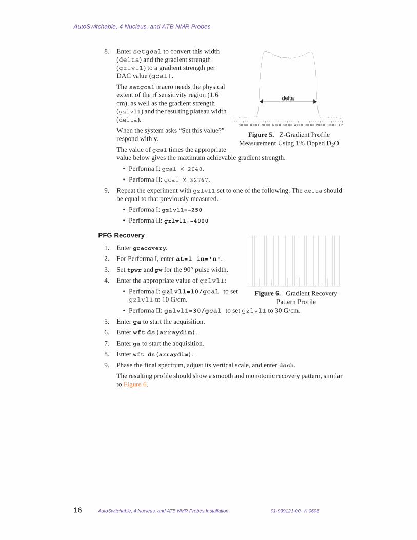
A peak (about 16 kHz for Performa I or about 50 kHz for Performa II) similar to Figure 5 is displayed.
7. Find the width of the peak at 20% of the height using the cursors.
Figure 4. 1H Lineshape Spinning Measurement
Hz-120-100-80-60-40-20020406080100120140
13C satellite13C satellite
CHCl3 peak
0.11%
0.55%
AutoSwitchable, 4 Nucleus, and ATB NMR Probes
16 AutoSwitchable, 4 Nucleus, and ATB NMR Probes Installation 01-999121-00 K 0606
8. Enter setgcal to convert this width (delta) and the gradient strength (gzlvl1) to a gradient strength per DAC value (gcal).
The setgcal macro needs the physical extent of the rf sensitivity region (1.6 cm), as well as the gradient strength (gzlvl1) and the resulting plateau width (delta).
When the system asks “Set this value?” respond with y.
The value of gcal times the appropriate value below gives the maximum achievable gradient strength.
• Performa I: gcal × 2048.
• Performa II: gcal × 32767.
9. Repeat the experiment with gzlvl1 set to one of the following. The delta should be equal to that previously measured.
• Performa I: gzlvl1=–250
• Performa II: gzlvl1=–4000
PFG Recovery
1. Enter grecovery.
2. For Performa I, enter at=1 in='n'.
3. Set tpwr and pw for the 90° pulse width.
4. Enter the appropriate value of gzlvl1:
• Performa I: gzlvl1=10/gcal to set gzlvl1 to 10 G/cm.
• Performa II: gzlvl1=30/gcal to set gzlvl1 to 30 G/cm.
5. Enter ga to start the acquisition.
6. Enter wft ds(arraydim).
7. Enter ga to start the acquisition.
8. Enter wft ds(arraydim).
9. Phase the final spectrum, adjust its vertical scale, and enter dssh.
The resulting profile should show a smooth and monotonic recovery pattern, similar to Figure 6.
Figure 5. Z-Gradient Profile Measurement Using 1% Doped D2O
Hz100002000030000400005000060000700008000090000
delta
Figure 6. Gradient Recovery Pattern Profile
01-999121-00 K 0606 AutoSwitchable, 4 Nucleus, and ATB NMR Probes Installation 17
Calibrating and Testing Probes
1H Sensitivity
1. Insert the ethylbenzene sample.
2. Enter rtp('/vnmr/tests/H1sn') su.
3. Tune the probe.
4. Set the PW90 value that was determined from the 1H PW90 calibration.
5. Enter ga to acquire the spectrum.
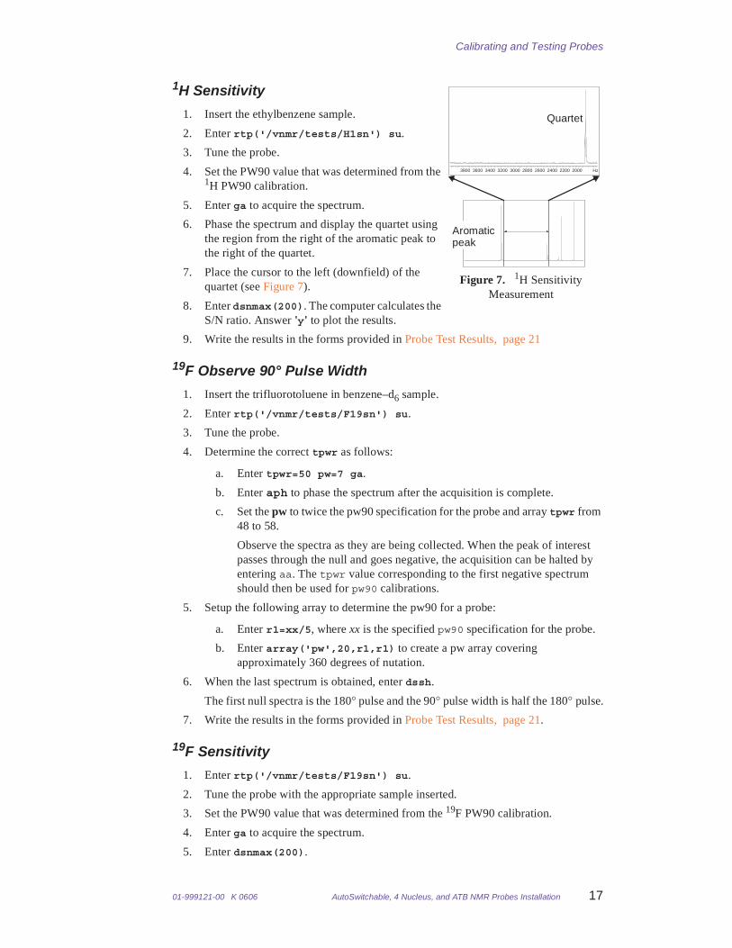
6. Phase the spectrum and display the quartet using the region from the right of the aromatic peak to the right of the quartet.
7. Place the cursor to the left (downfield) of the quartet (see Figure 7).
8. Enter dsnmax(200). The computer calculates the S/N ratio. Answer 'y' to plot the results.
9. Write the results in the forms provided in Probe Test Results, page 21
19F Observe 90° Pulse Width
1. Insert the trifluorotoluene in benzene–d6 sample.
2. Enter rtp('/vnmr/tests/F19sn') su.
3. Tune the probe.
4. Determine the correct tpwr as follows:
a. Enter tpwr=50 pw=7 ga.
b. Enter aph to phase the spectrum after the acquisition is complete.
c. Set the pw to twice the pw90 specification for the probe and array tpwr from 48 to 58.
Observe the spectra as they are being collected. When the peak of interest passes through the null and goes negative, the acquisition can be halted by entering aa. The tpwr value corresponding to the first negative spectrum should then be used for pw90 calibrations.
5. Setup the following array to determine the pw90 for a probe:
a. Enter r1=xx/5, where xx is the specified pw90 specification for the probe.
b. Enter array('pw',20,r1,r1) to create a pw array covering approximately 360 degrees of nutation.
6. When the last spectrum is obtained, enter dssh.
The first null spectra is the 180° pulse and the 90° pulse width is half the 180° pulse.
7. Write the results in the forms provided in Probe Test Results, page 21.
19F Sensitivity
1. Enter rtp('/vnmr/tests/F19sn') su.
2. Tune the probe with the appropriate sample inserted.
3. Set the PW90 value that was determined from the 19F PW90 calibration.
4. Enter ga to acquire the spectrum.
5. Enter dsnmax(200).
Figure 7. 1H Sensitivity Measurement
Hz2000220024002600280030003200340036003800
Quartet
Aromaticpeak

AutoSwitchable, 4 Nucleus, and ATB NMR Probes
18 AutoSwitchable, 4 Nucleus, and ATB NMR Probes Installation 01-999121-00 K 0606
The computer calculates the S/N ratio. Answer 'y' to plot the results.
6. Write the results in the forms provided in Probe Test Results, page 21.
31P Observe 90° Pulse Width
1. Insert the triphenylphosphate sample.
2. Enter rtp('/vnmr/tests/P31sn') su.
3. Install the 31P 1/4 wavelength cable.
4. Tune the probe observe channel without using the filter.
5. Enter gain=50 ga.
6. Phase the spectrum, place the cursor on the 31P resonance, and enter movetof.
7. Determine the correct tpwr as follows:
a. Enter tpwr=44 pw=7 ga.
b. After the acquisition is complete, enter aph to phase the spectrum.
c. Set the pw to twice the pw90 specification for the probe and array tpwr from 48 to 58.
Observe the spectra as they are being collected. When the peak of interest passes through the null and goes negative, the acquisition can be halted by entering aa. The tpwr value corresponding to the first negative spectrum should then be used for pw90 calibrations.
8. Setup the following array to determine the pw90 for a probe:
a. Enter r1=xx/5, where xx is the specified pw90 specification for the probe.
b. Enter array('pw',20,r1,r1) to create a pw array covering approximately 360 degrees of nutation.
9. When the last spectrum is obtained, enter dssh.
The first null spectra is the 180° pulse; therefore, the 90° pulse width is one-half the 180° pulse.
10. Write the results in the forms provided in Probe Test Results, page 21.
31P Sensitivity
1. Insert the triphenylphosphate sample.
2. Enter rtp('/vnmr/tests/P31sn') su.
3. Tune the probe with the appropriate sample inserted.
4. Set the PW90 value that was determined from the 31P PW90 calibration.
5. Enter ga.
6. Enter dsnmax(2000).
The computer calculates the S/N ratio. Answer 'y' to plot the results.
7. Write the results in the forms provided in Probe Test Results, page 21.
13C Observe 90° Pulse Width
1. Insert the ASTM sample.
2. Enter rtp('/vnmr/tests/C13sn') su.
3. Install the 13C 1/4 wavelength cable.

01-999121-00 K 0606 AutoSwitchable, 4 Nucleus, and ATB NMR Probes Installation 19
Calibrating and Testing Probes
4. Tune the probe.
5. Enter a dpwr 3 or 4 dB less than dpwr of γH2, dm='nny' d1=10 su.
6. Enter ga.
7. Place the cursor in the center of the dioxane triplet and type movetof.
8. Enter pw=5 at=2 lb=3.5 fn=4096. Obtain the spectrum and adjust the phase for a positive signal.
9. Array dof to set the decoupler frequency on the dioxane 1H resonance.
Optimize the position of the decoupler (dof) to within 0.4 Hz of the correct frequency to obtain the best possible resolution.
10. Expand the spectrum so that the signal is centered on the screen with wp=100.
11. Enter ai.
12. Change vs so that the signal occupies about half the vertical size of the screen and set vp=50.
13. Determine the correct tpwr as follows:
a. Enter tpwr=44 pw=7 ga.
b. Enter aph to phase the spectrum after the acquisition completes.
c. Set the pw to twice the pw90 specification for the probe.
d. Array tpwr from 48 to 58.
Observe the spectra as they are being collected. When the peak of interest passes through the null and goes negative, the acquisition can be halted by entering aa. The tpwr value corresponding to the first negative spectrum should then be used for pw90 calibrations.
14. Setup the following array to determine the pw90 for a probe:
a. Enter r1=xx/5, where xx is the specified pw90 specification for the probe.
b. Enter array('pw',20,r1,r1) to create a pw array covering approximately 360 degrees of nutation.
15. Enter d1=30 ga.
16. Enter dssh after the last spectrum is obtained. Change vs if necessary.
17. Determine pw for the first minimum.
This is the 180° pulse. The 90° pulse is one-half the 180° pulse.
18. Write the results in the forms provided in Probe Test Results, page 21.
13C Spinning Resolution & Lineshape
This test measures the 50%, 0.55%, and 0.11% levels of the ASTM sample and is not required for ATB probes. This test and the 13C spinning sidebands test (the next test) must be passed simultaneously.
1. Insert the appropriate ASTM sample in the probe and spin it.
2. Enter rtp('/vnmr/tests/C13res') su.
3. Tune the probe. Enter nt=1.
4. Change the decoupler power dpwr to 3 or 4 dB below the dpwr of γH2.
This will be the dpwr for 1H in the probe file.
5. Array dof to set the decoupler frequency on the dioxane 1H resonance.

AutoSwitchable, 4 Nucleus, and ATB NMR Probes
20 AutoSwitchable, 4 Nucleus, and ATB NMR Probes Installation 01-999121-00 K 0606
To obtain the best possible resolution, it may be necessary to optimize the position of the decoupler (dof) to within 0.4 Hz of the correct frequency.
6. Enter ga to acquire the spectrum.
7. Save the spectrum — use this spectrum for 13C spinning sideband test.
8. Measure the linewidth and plot the spectrum as follows:
a. Set wp=50. Enter res to determine the linewidth at 50% of the decoupled peak and plot the spectrum.
b. Increase vs by 100 times, plot the expanded spectrum, and measure the linewidth at 0.55% and 0.11%.
9. Write the results in the forms provided in Probe Test Results, page 21.
13C Spinning Sidebands
This test (not required for ATB probes) and the 13C spinning resolution and lineshape test (the previous test) must be passed simultaneously.
1. Use the spectrum obtained for the 13C lineshape and resolution and test and measure the 13C spinning sidebands.
2. Measure spinning sideband amplitudes as a percentage of the peak as follows.
a. Plot the spectrum again using a large enough value of wp to show all the spinning sidebands, including fourth order.
Spinning sidebands occur at integer multiples of the spinning rate and appear symmetrically about of the central peak.
b. The standard test uses nt=4. If sidebands meet specifications at nt=4, repeating the test at nt=16 is unnecessary.
3. Write the results in the forms provided in Probe Test Results, page 21.
13C Sensitivity
The specification for the 13C lineshape and resolution test must be met before performing this test.
1. Enter rtp('/vnmr/tests/C13sn') su.
2. Tune the probe with the appropriate sample inserted.
3. Set the 13C 90° pulse width to the value determined in the calibration.
4. Enter ga.
5. Wait at least 8 minutes between acquisitions to ensure that the C6D6 lines are fully relaxed.
The signal of interest is the highest line of the C6D6 triplet (see Figure 8).
6. Use the cursors to select the best 1400 Hz noise region between the dioxane and benzene peaks.
7. Enter dsnmax(1400).
8. Plot the results and record the value on the spectrum.
9. Write the results the forms provided in Probe Test Results, page 21.
Figure 8. 13C Sensitivity
Hz7000800090001000011000120001300014000
Benzene-d6
p-Dioxane

01-999121-00 K 0606 AutoSwitchable, 4 Nucleus, and ATB NMR Probes Installation 21
Probe Test Results
Probe Test Results• Probe Test Results for 4-nuc and ASW, page 22
• Probe Test Results for ATB, page 23
All specifications are subject to change without notice. The specifications supplied with the probe shall prevail unless customer contract determines otherwise.
Specifications are for probes installed with currently-shipping Varian, Inc. NMR systems. No guarantee is given that probes purchased for use in systems other than currently-shipping will meet current specifications.
Tests are performed with the following sample tubes:
• 5-mm probes: 5-mm tubes with 0.38-mm wall (Wilmad 528-PP, or equivalent).
• Using sample tubes with thinner wall thickness (e.g., Wilmad 5-mm 545-PPT, or equivalent) increases signal-to-noise.
AutoSwitchable, 4 Nucleus, and ATB NMR Probes
22 AutoSwitchable, 4 Nucleus, and ATB NMR Probes Installation 01-999121-00 K 0606
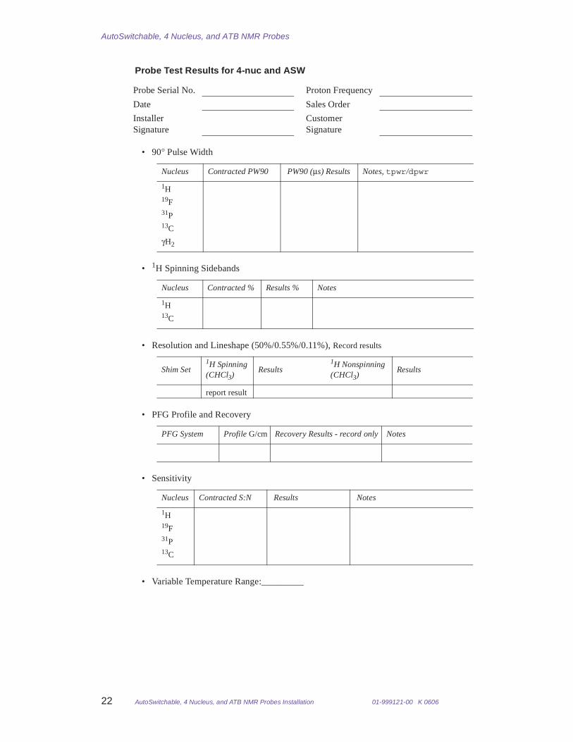
Probe Test Results for 4-nuc and ASW
• 90° Pulse Width
• 1H Spinning Sidebands
• Resolution and Lineshape (50%/0.55%/0.11%), Record results
• PFG Profile and Recovery
• Sensitivity
• Variable Temperature Range:_________
Probe Serial No. Proton Frequency
Date Sales Order
Installer Signature
Customer Signature
Nucleus Contracted PW90 PW90 (µs) Results Notes, tpwr/dpwr
1H19F31P13C
γH2
Nucleus Contracted % Results % Notes
1H13C
Shim Set1H Spinning(CHCl3)
Results1H Nonspinning(CHCl3)
Results
report result
PFG System Profile G/cm Recovery Results - record only Notes
Nucleus Contracted S:N Results Notes
1H19F31P13C
01-999121-00 K 0606 AutoSwitchable, 4 Nucleus, and ATB NMR Probes Installation 23
Probe Test Results
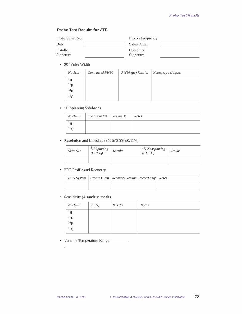
Probe Test Results for ATB
• 90° Pulse Width
• 1H Spinning Sidebands
• Resolution and Lineshape (50%/0.55%/0.11%)
• PFG Profile and Recovery
• Sensitivity (4-nucleus mode)
• Variable Temperature Range:_________
.
Probe Serial No. Proton Frequency
Date Sales Order
Installer Signature
Customer Signature
Nucleus Contracted PW90 PW90 (µs) Results Notes, tpwr/dpwr
1H19F31P13C
Nucleus Contracted % Results % Notes
1H13C
Shim Set1H Spinning(CHCl3)
Results1H Nonspinning(CHCl3)
Results
PFG System Profile G/cm Recovery Results - record only Notes
Nucleus (S:N) Results Notes
1H19F31P13C

AutoSwitchable, 4 Nucleus, and ATB NMR Probes
24 AutoSwitchable, 4 Nucleus, and ATB NMR Probes Installation 01-999121-00 K 0606
AutoSwitchable, 4 Nucleus, and ATB NMR ProbesPub. No. 01-999121-00, Rev. K 0606
Technical contributor: Knut Mehr, Rob Rice, John Sandoval, Carlos Gil, Bao Nguyen, Susan KleinTechnical writer and editor: Everett Schreiber
Revision history:A0599 – Initial release, ER 2750B1099 – ECO 8703; updated S/N specs, added tuning chart sectionC1099 – ECO 8719; changed MERCURY S/N 1H and 19F specs (10/29/99).D0501 – Updated probe part numbers per ECO 9108. E0501 – 300- and 400-MHz ATB probes; Updated S/N specs for MERCURYplus ECO 9140 F0901 – Added specs to 300 ATB probe for MERCURY 300 4-nuc per ECO 9207G0902 – Updated specifications per ECO 9466H1002 – Added Magnet Interface Box updatesI0104 – Updated specificationsJ0505 – General updatesK0606– Added probes and updates per ECO 13019, updated parameter files and macros for VnmrJ2.1B
Copyright © 2006, Varian, Inc. 3120 Hansen Way, Palo Alto, California 943041-800-356-4437http://www.varianinc.comAll rights reserved. Printed in the United States
The information in this document has been carefully checked and is believed to be entirely reliable. However, no responsibility is assumed for inaccuracies. Statements in this document are not intended to create any warranty, expressed or implied. Specifications and performance characteristics of software and hardware described in this manual may be changed at any time without notice. Varian reserves the right to make changes in any products herein to improve reliability, function, or design. Varian does not assume any liability arising out of the application or use of any product or circuit described herein; neither does it convey any license under its patent rights nor the rights of others. Inclusion in this document does not imply that any particular feature is standard on the instrument.
AutoSwitchable, ATB, VnmrS, UNITYINOVA, and MERCURYplus registered trademarks or trademarks of Varian, Inc. Other product names are trademarks of their respective holders.


