0..11 EECC DDeeccllaarraattiioonn ooff CCoonnffoorrmmiittyy
24
A720E Temperature Regulation Systems 0 0 0 . . . 1 1 1 E E E C C C D D D e e e c c c l l l a a a r r r a a a t t t i i i o o o n n n o o o f f f C C C o o o n n n f f f o o o r r r m m m i i i t t t y y y We: FHC Europe (TERMOBIT PROD srl) of: 129 Barbu Vacarescu Str, Sector 2 Bucharest 020272 Romania declare that: Equipment: Temperature Regulation Systems Model: Catalog No.s 40-90-8D, 40-90-5D-02, 40-90-3, 40-90-6, 40-90-2-XX Serial Number: ___________ has been designed and manufactured to the following specifications: IEC61326 Electrical Equipment for Measurement, Control, and Laboratory Uses I hereby declare that the equipment named above has been designed to comply with the relevant sections of the above referenced specifications. The unit complies with all essential requirements of the Directives. Signed by: __________________________________Date: ____________________ Name: Frederick Haer Position: President , FHC Done at: FHC Inc., 1201 Main Street, Bowdoin, ME 04287 USA Phone: 1207-666-8190, Fax: 207-666-8292 E-mail: [email protected], Website: http://www.fh-co.com
Transcript of 0..11 EECC DDeeccllaarraattiioonn ooff CCoonnffoorrmmiittyy

A720E Temperature Regulation Systems
000...111 EEECCC DDDeeeccclllaaarrraaatttiiiooonnn ooofff CCCooonnnfffooorrrmmmiiitttyyy
We: FHC Europe (TERMOBIT PROD srl)
of:
129 Barbu Vacarescu Str, Sector 2 Bucharest 020272 Romania
declare that:
Equipment: Temperature Regulation Systems
Model: Catalog No.s 40-90-8D, 40-90-5D-02, 40-90-3, 40-90-6, 40-90-2-XX
Serial Number: ___________
has been designed and manufactured to the following specifications:
IEC61326 Electrical Equipment for Measurement, Control, and Laboratory Uses
I hereby declare that the equipment named above has been designed to comply with the relevant sections of the above referenced specifications. The unit complies with all essential requirements of the Directives.
Signed by: __________________________________Date: ____________________
Name: Frederick Haer
Position: President , FHC
Done at: FHC Inc., 1201 Main Street, Bowdoin, ME 04287 USA
Phone: 1207-666-8190, Fax: 207-666-8292
E-mail: [email protected], Website: http://www.fh-co.com

A720E Temperature Regulation Systems
A720E Temperature Regulation Systems
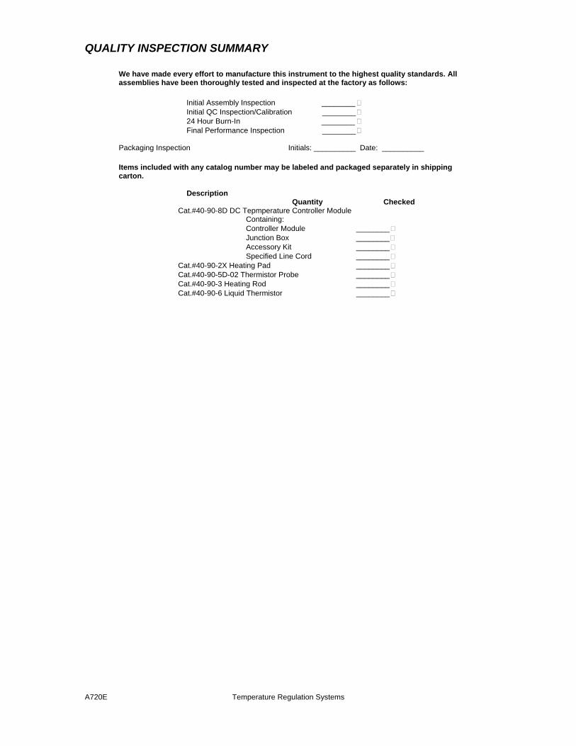
QUALITY INSPECTION SUMMARY
We have made every effort to manufacture this instrument to the highest quality standards. All assemblies have been thoroughly tested and inspected at the factory as follows:
Initial Assembly Inspection ________ Initial QC Inspection/Calibration ________ 24 Hour Burn-In ________ Final Performance Inspection ________
Packaging Inspection Initials: __________ Date: __________ Items included with any catalog number may be labeled and packaged separately in shipping carton.
Description Quantity Checked
Cat.#40-90-8D DC Tepmperature Controller Module Containing: Controller Module ________ Junction Box ________ Accessory Kit ________ Specified Line Cord ________
Cat.#40-90-2X Heating Pad ________ Cat.#40-90-5D-02 Thermistor Probe ________ Cat.#40-90-3 Heating Rod ________ Cat.#40-90-6 Liquid Thermistor ________

A720E Temperature Regulation Systems

A720E Temperature Regulation Systems
“Innovation through collaboration”
Providing Instrumentation and
Apparatus for Cellular Research, Intraoperative Recording, and
Microneurography; Micro-electrodes, Micropipettes, and Needles to the
Neuroscience Community for 30 years.
Temperature Regulation
Systems 40-90-8D DC Temperature Controller 40-90-5D-02 Rectal Thermistor Probe 40-90-3 Liquid Immersion Heating Rod 40-90-6 Liquid Thermistor Insert 40-90-2-XX Heating Pads
FHC Headquarters 1201 Main Street,
Bowdoin, ME, 04287 USA Fax: 207-666-8292
E-mail: [email protected] www.fh-co.com
24 hour technical service
+1-207-666-8190 1-800-326-2905(US & Can)
FHC Europe (TERMOBIT PROD srl)
129 Barbu Vacarescu Str, Sector 2
Bucharest 020272 Romania
L005-18B

A720E Temperature Regulation Systems

A720E Temperature Regulation Systems
TABLE OF CONTENTS
Manual A720E: Temperature Regulation Systems 40-90-8D DC Temperature Controller 40-90-5D-02 Rectal Thermistor Probe 40-90-3 Liquid Immersion Heating Rod 40-90-6 Liquid Thermistor Insert 40-90-2-XX Heating Pads
0 Declarations 0.1 Declaration Of Conformity 0.2 Conditions For Use 0.3 Symbols Used 1 Operational Manual 1.1 Features 1.2 Description 1.3 Operating Environment 1.4 Inventory 1.4.1 Items Described In This Manual 1.4.2 Additional Items Required For Operation 1.4.3 Replacement Items 1.4.4 Optional Accessories 1.4.5 System Configurations 1.5 Concepts 1.5.1 Terminology 1.5.2 Design Description 1.6 Technical Summary
1.6.1 Specifications 1.6.2 Controls / Connectors 1.6.3 Compatibilities
1.7 Illustrative Procedure 2 Reference Manual 2.1 Reference Information
2.1.1 Packaging 2.1.2 Mounting 2.1.3 Inspection 2.1.4 Power Connections 2.1.5 Warranty 2.1.6 Policies 2.1.7 Service
2.2 Installation 2.3 Functional Checkout
2.3.1 Calibration 2.4 Operational Information 2.5 Scheduled Maintenance

A720E Temperature Regulation Systems
A720E Temperature Regulation Systems
0.2 CONDITIONS FOR USE
Intended Use The Temperature Regulation Systems are used to maintain constant temperatures of subjects or liquid.
Warnings The Temperature Regulation Systems components should not be disassembled beyond their major assemblies. Any disassembly beyond this may affect function and calibration. If repair is required please contact FHC at (207) 666-8190 for evaluation and to secure a return authorization number if necessary.
In animal applications, a blanket or similar insulating material should be placed between the heating pad and support plate. Additionally the rectal thermistor probe should be taped in place once inserted. In liquid heating applications, care should be taken to keep the instrumentation and cabling in a dry place.
Storage Precautions Store at normal room temperatures between -34°C (-29°F) and 57°C (135°F). Do not expose to temperatures below -39°C (-29°F) or greater than 70°C (158°F), or a relative humidity of less than 10% or more than 100%, including condensation, or an atmospheric pressure less than 500hPa or greater than 1060hPa for long-term storage.
Sterilization The Rectal Thermistor Probe can be sterilized by dipping the tip into a sterilizing agent previous to use. No other sterilization methods are recommended.
Handling While a high degree of durability has been designed into the Temperature Regulation Systems components, care should be taken not to drop them. Place all cables and leads where they will not be inadvertently pulled or tangled.
0.3 SYMBOLS USED
None used

A720E Temperature Regulation Systems
1 OPERATIONAL MANUAL
1.1 FEATURES
• 25° - 45°C Heating Range, 40 Watt capacity • Proportional DC voltage does not generate electrical noise, no switching transient • Thermistor probes and heating elements available for all lab applications • Analog output of heater output for chart recording or other biological recording devices • Compatible with other probes (ex. YSI 400) through factory modification • Desktop or rack mountable
1.2 DESCRIPTION
The DC Temperature Regulation Systems are designed to maintain a constant temperature of a subject or liquid without introduction of electrical interference. The proportional DC power supply slowly varies its output to the heating element based on the resistance of the monitoring thermistor. Electrical noise and switching transients common in AC-based devices is eliminated.
The DC Temperature Controller (40-90-8D) is powered through an internal power supply (country specific line cord ordered separately). It has an easy-to-read three digit LED display on the front panel indicating the subject or liquid temperature in tenths of a degree Celsius. Failing thermistors or similar electrically "open" situations are indicated by a red LED on the front panel labeled "OPEN"
A junction box is provided with the Controller, which connects to the module via a 2.5m shielded cable (extension cable available); thermistors and heating elements plug into this box.
The 40-90-5D-02 Rectal Thermistor Probe is small enough (.062"/1.6mm diameter) to maintain the body temperature of a range of mammals (mouse, rat, cat etc.). Heating pads (40-90-2-XX) are available in sizes suitable for any application.
The 40-90-3 Liquid Immersion Heating Rod and 40-90-6 Liquid Thermistor Insert can heat up to 1L of liquid and maintain a constant temperature to serve as a water bath or warmed perfusate.
FHC thermistors utilize 5000Ohm resistance. The DC Temperature Controller can be factory configured for 2252Ohm thermistors, e.g. YSI 400 series, and factory-moified for other heating elements (contact FHC Technical Support for more information).
An analog output provides a voltage related to the measured temperature (100mV/°C) for use with biofeedback recording systems. (ex. Chart recorders etc.)
The DC Temperature Controller contains an internal power supply that can be user-configured for 50 or 60Hz. Country specific line cords are ordered separately. The module is compact and can be placed as a stand-alone unit on a desktop, or mounted in a standard 19" instrument rack with our SAF rack frame.
A720E Temperature Regulation Systems
1.3 OPERATING ENVIRONMENT
The Temperature Regulation System components have been designed to operate in a typical laboratory setup. They should be placed on a flat surface that is level and free from contaminants and vibration.
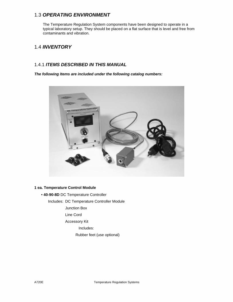
1.4 INVENTORY
1.4.1 ITEMS DESCRIBED IN THIS MANUAL
The following Items are included under the following catalog numbers:
1 ea. Temperature Control Module
• 40-90-8D DC Temperature Controller
Includes: DC Temperature Controller Module
Junction Box
Line Cord
Accessory Kit
Includes:
Rubber feet (use optional)
A720E Temperature Regulation Systems
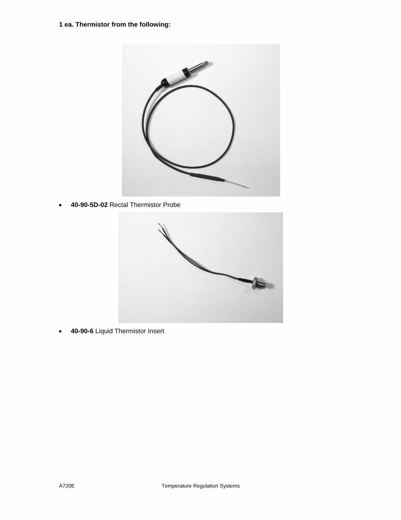
1 ea. Thermistor from the following:
• 40-90-5D-02 Rectal Thermistor Probe
• 40-90-6 Liquid Thermistor Insert

A720E Temperature Regulation Systems
1 ea. Heating Element from the following:
• 40-90-2-02 25X25cm Heating Pad • 40-90-2-05 10X12.5cm Heating Pad • 40-90-2-06 6.5X9.5cm Heating Pad • 40-90-2-07 5X12.5cm Heating Pad • 40-90-3 Liquid Immersion Heating Rod
1.4.2 ADDITIONAL ITEMS REQUIRED FOR OPERATION None Required 1.4.3 REPLACEMENT ITEMS Thermistors and Heating elements may be ordered separately. 1.4.4 OPTIONAL ACCESSORIES The following accessories are available:
55-11-0 SAF Rack Frame for Stand-Alone Modules
1.4.5 SYSTEM CONFIGURATIONS

A720E Temperature Regulation Systems
As an animal temperature regulation system
As a bath temperature regulation device
1.5 CONCEPTS
1.5.1 TERMINOLOGY
A720E Temperature Regulation Systems
Thermistor: A thermistor is a device whose resistance changes in proportion to its temperature. It is used to measure the temperature of an animal subject or of bath medium.
1.5.2 DESIGN DESCRIPTION
The DC Temperature Controller (Cat. #40-90-8D) generates a DC voltage that is proportional to the difference between the temperature set by a front panel potentiometer and the temperature sensed by a thermistor. Using this DC voltage to drive a heating element results in a closed-loop system for regulating temperature about the set-point established by the front panel control. Using a proportional DC voltage for the heater eliminates the noise-producing spikes associated with temperature controllers that switch the heater off and on to regulate temperature.
1.6 TECHNICAL SUMMARY
1.6.1 SPECIFICATIONS
DC Temperature Controller:
Output Voltage: 0-35V DC (Ripple<25mV peak to peak) Output Current: 0-1A
Temperature Range: 25°C - 45°C Temperature Display: 3 Digit LED indicating
temperature in degrees and .1degrees C Temperature Accuracy: .2°C Thermistor
Resistance Required: Standard Configuration: 5000Ohms at 25°C Heater Element Resistance Required: 35 Ohms minimum Power Requirements: 100-240 VAC, 50-60Hz Dimensions:
Height: 13cm (5.22")
Width: 10cm (4.20")
Length: 25cm (9.75")
Weight: 1.48 Kg (3.26 lbs)
Mounting Options:
Tabletop, 4 rubber feet prevent sliding.
Rack mountable with SAF Rack Frame (Cat. #55-11-0 Available separately)
1.6.2 CONTROLS/CONNECTORS
A720E Temperature Regulation Systems
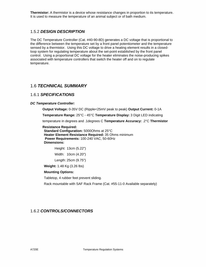
Display - DC Temperature Controller Front Panel: Temperature: 3 digit LED display of the temperature read from the thermistor to .1°C Open: Red LED display warning of an open thermistor circuit
Controls - DC Temperature Controller Front Panel:
Target: Graduated dial for setting the target subject/liquid temperature. See section 2.4 for setting/temperature chart
Connections - DC Temperature Controller Front Panel:
Heater/Sensor: 4 conductor socket for connecting the thermistor/heating element junction box
A720E Temperature Regulation Systems
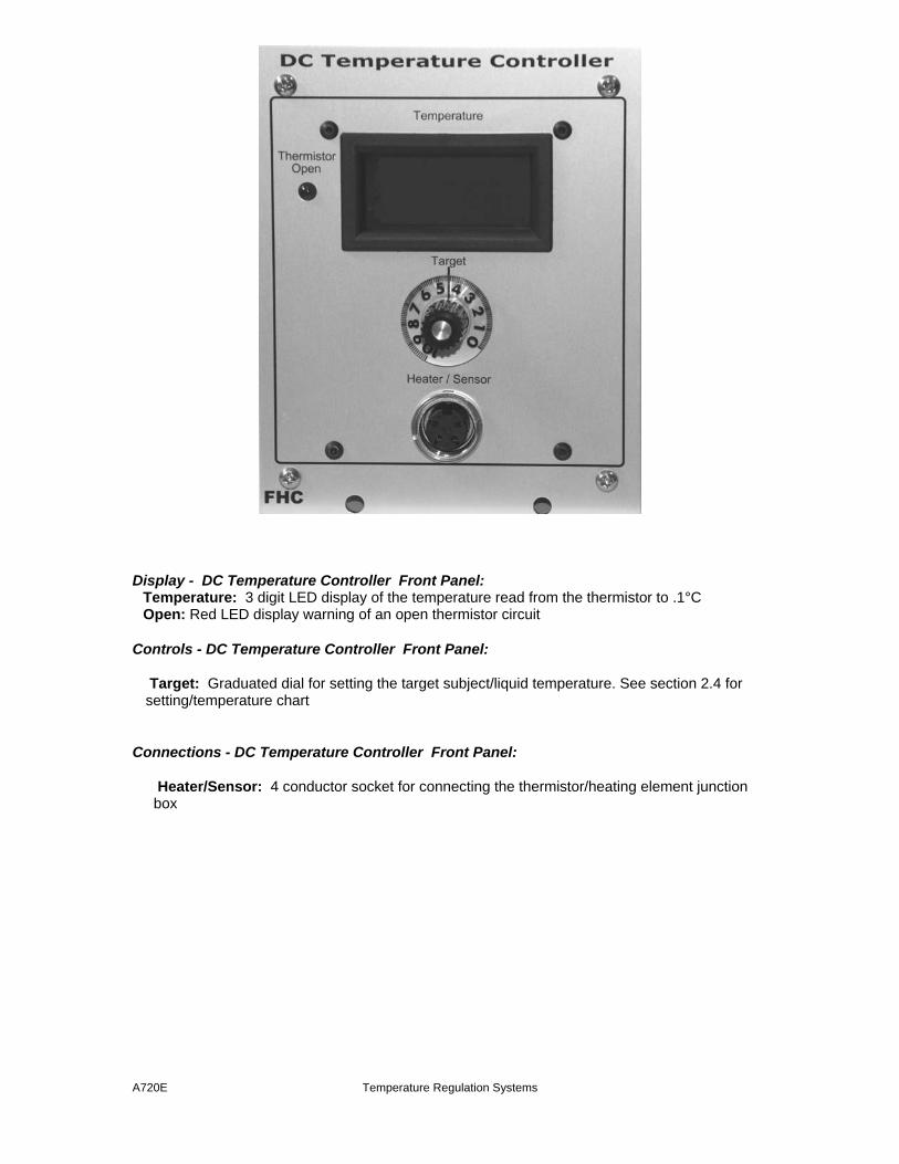
Controls - DC Temperature Controller Back Panel:
0|I: Rocker switch used to activate power.
Connections - DC Temperature Controller Back Panel:
Line Voltage: Voltage selector for 115 or 230V line voltage Fuse: Holder for 2 Slo-Blo fuses Power: 6-ft. (2m) line cord with 3-pronged plug Analog Output: Male BNC connector providing proportional voltage of thermistor's temperature measurement (100mV/°C)
1.6.3 COMPATIBILITIES
The DC Temperature Controller comes factory calibrated to work with thermistors of 5000Ohms at 25°C and heating elements of 35 Ohms minimum. We are happy to recalibrate or modify it for use with other thermistors or elements. (Contact FHC Technical Support for details)
1.7 ILLUSTRATIVE PROCEDURE
Temperature regulation in animal applications:

A720E Temperature Regulation Systems
1. Position animal in stereotaxic. 2. Slide the Heating Pad between the animal and a suitable insulating material. Direct contact
between the Heating Pad and stereotaxic support plate is not advised. 3. Insert Rectal Thermistor Probe into the animal and tape in place. 4. Connect the Junction Box to the controller 5. Plug the Rectal Thermistor Probe and Heating Pad leads into the Junction Box. 6. Adjust controller to the desired target temperature using the Target knob. (ex. "6" for 37°C) Temperature regulation in liquid applications
1. Thread the Liquid Thermistor Insert and Liquid Immersion Heating Rod into the bath sidewalls so that they will be completely immersed.
2. Fill the bath with water and cover. It is recommended that the bath water circulate. 3. Connect the Junction Box to the controller 4. Adjust controller to the desired target temperature using the Target knob (ex. "6" for 37°C)
2 REFERENCE MANUAL
2.1 REFERENCE INFORMATION

A720E Temperature Regulation Systems
2.1.1 PACKAGING The stand-alone modules of the neuro/craft™ series instruments are packaged in metal cases, which consist of standard 5.25" high front panels. Front panel widths are specified as Type 2 modules (2.05" actual), Type 4 modules (4.15" actual), and Type 6 modules (6.25" actual) Front panels are mounted on extruded top and bottom panels. Flat side panels slide into slots in the extrusions, and are held in place when the back panel is secured into the extrusion. All modules are 9.75" in depth.
Type 2 Module Type 4 Module Type 6 Module
2.1.2 MOUNTING
All stand-alone modules are completely encased and can be used without further mounting or hardware. Provided rubber feet may be used to protect surfaces from scratching. However, it may be suitable to group modules, and we have made provision for several configurations. The SAF Rack Frame for Stand-Alone Modules (cat #55-11-0) will hold up to eight Type 2 modules, four Type 4 modules, or two Type 6 modules and 2 ea. Type 2 Dress Panels (cat #55-11-1 use optional), while occupying only 3 rack units (5.25") vertically on a standard 19” instrument rack. Several combinations are available for all of the neuroCraft series stand-alone modules. For example an SAF frame could accommodate 3-Type 2, 1-Type 4, and 1-

A720E Temperature Regulation Systems
Type 6 within its 16" of horizontal rack space.
SAF Rack Frame For Stand-Alone Modules (Shown with a neuroCraft Type 2 Module)
Dress Panels for SAF (Ordered Separately): • 55-11-1 Type 2 Dress Panel
2.1.3 INSPECTION
FHC Modules are factory checked and calibrated but should be carefully inspected upon receipt, before using, or activating power. If any exterior damage to the shipping carton is noted, the instrument(s) should be inspected for obvious physical damage. The contents of each package should be physically checked against the inventory list (sec. 1.3) to determine shortages or errors in inventory.
2.1.4 POWER CONNECTIONS
All of the stand-alone modules in the neuro/craft series are powered by an internal universal power supply that accepts inputs of 85-265VAC, 50-60Hz. An international pattern Line Cord (not shown) is ordered separately, and is specified by country per the catalog number. (See table below for catalog numbers.)
66-EL-LC-AUS Australia 66-EL-LC-CH China 66-EL-LC-DAN Denmark 66-EL-LC-EURO Europe 66-EL-LC-ISR Israel 66-EL-LC-ITA Italy
A720E Temperature Regulation Systems
66-EL-LC-JA Japan 66-EL-LC-SAF South Africa 66-EL-LC-SWI Switzerland 66-EL-LC-UK United Kingdom 55-USA North America
2.1.5 WARRANTY
All FHC products are unconditionally guaranteed against defects in workmanship for one year from date of shipment as long as they have been exposed to normal and proper use. Although the one- year warranty may have expired, please contact our Service Department before attempting any repairs or alterations. Many of these repairs will still be performed at the factory at no charge to the customer.
2.1.6 POLICIES
TECHNICAL SUPPORT: It is our policy to provide our customers with the most comprehensive technical support in the industry. If any questions arise or problems occur, we encourage you to call or write and we promise to promptly and comprehensively respond to your requirements.
TRADE-UP POLICY: It is our policy to offer customers trade-up ability as new and/or expanded capabilities for their instruments are announced. In many cases, full credit will be given. In general, we will allow 100% credit for two years and depreciate 20% per year thereafter. Please contact our Marketing Department for information relating to your particular situation.
2.1.7 SERVICE
Should service be required, please contact our Service Department for a return authorization number and instructions (207-666-8190). Please have the model and serial number on hand (Both are located on the back panel). Carefully pack the instrument before returning. Please include a note indicating:
1. The model number and purchase date of the instrument 2. The person to contact if questions arise 3. The "symptoms" indicating that repair is necessary
If the instrument is not covered by the warranty, a quotation will be forwarded to the sender detailing the repairs necessary and charges, before repair is begun.
2.2 INSTALLATION
1. Attach rubber feet to bottom corners of the DC Temperature Controller module if mounting on a desktop. If rack-mounting in the SAF Rack Frame, install the device and tighten the front panel thumbscrew before plugging in any cabling. 2. Plug the line cord into the power outlet on the back panel. 3. Attach the junction box connector into the socket on the front panel. Turn clockwise to tighten.
A720E Temperature Regulation Systems
4. Plug the thermistor and heating element leads into the junction box. 5. Route cables so that they can't be inadvertently pulled or tangled.
2.3 FUNCTIONAL CHECKOUT
Equipment needed: Oscilloscope or voltmeter
1. Connect junction box to Temperature Control module. Plug heater into junction box jacks. Connect the decade resistance box ("R") to the thermistor jacks of the junction box. Connect the oscilloscope or the voltmeter across the heater; + to terminal number 4, - to terminal number 3 (see Dwg.40-90-8C(1/1). If a liquid heating rod is used, it must be immersed in water; no such precaution is necessary with the heating pad. 2. Turn the Temperature Control Module on. Set the TEMPERATURE control to zero. Vary "R". When "R" is higher than approximately 5000 ohms, the heater voltage should rise to about 29-32 volts; lower values of "R" should cause this voltage to fall to near zero. When “R” is 5000 ohms, the Analog Output should measure approximately 0V. 3. Set the TEMPERATURE control to 10. When "R" is higher than approximately 2200 ohms, the heater voltage should rise to 29-32 volts; lower values of "R" should cause this voltage to fall to near zero. 4. Set "R" to 2100 ohms; display should read 46.0 degrees and the Analog Output should at 2.1V. Set "R" to 5000 ohms; display should read 25.0 degrees. Also, the Analog Output should measure approximately 0mV. 5. Disconnect the thermistor. The THERMISTOR OPEN LED should light and the heater voltage should fall to near zero. 6. Check the magnitude of noise on the output. With a 60-Ohm, load (e.g. a 40-90-2 heating pad). the maximum AC ripple should be 25mV peak-to-peak when the DC output is maximum ("R" greater than 5000 Ohms).
2.3.1 Calibration
1. Mechanically align the calibrated knob on the front panel potentiometer shaft so that the full clockwise position lines up with “1” on the number 10. Tighten knob screw when finished. Note: Trimpots T1 and T2 along with test points Tp1 and Tp2 are all located on the front panel circuit board (1057C1.00). Trimpots T3, T4, and T5 along with test points Tp3 and Tp4 are all located on the main circuit board (1148C1.00). 2. Connect a heating pad to the output and the decade resistance box (R) to the thermister input of the module. Set R to 5000 Ohms. Adjust T2 for a voltage of 3.4V at Test Point 2 (Tp2). Adjust T1 for a voltage of 3.3V at Test Point 1 (Tp1). 3. Set R to 2100 Ohms. Adjust T1 for a digital display reading of 46.0 degrees. 4. Set R to 5000 Ohms. Adjust T2 for a digital display reading of 25.0 degrees. (Note: Steps 3 and 4 interact and should be repeated until both specified display readings are obtained.)

A720E Temperature Regulation Systems
5. Set R to 5000 for a digital display reading of 25.0 degrees. Connect the Analog Output(BNC connector) of the Temperature Controller to channel 2 of the oscilloscope. Adjust T5 so that the measure voltage equals as close to 0V as possible. (Note: It is possible to adjust T5 too far and still have the Analog output equal 0V. For example, the minimum value of the Analog output may be 4mV. Adjust T5 until the output reaches 4mV but don’t adjust T5 any further. Likewise, the Analog output may already be at 4mV, so T5 should be adjusted to the exact point where the Analog output starts to increase.) 6. Set R to 2100 Ohms. Confirm that the digital display reads 46.0. Adjust T6 so that the Analog output equal 2.1V. Set R to 2184 Ohms. Confirm that the digital display reads 45.0 and the Analog output equals 2.0V. 7. Adjust R, the decade resistance box, for a digital display reading of 25 degrees (R = 5000 Ohms). Set the TEMPERATURE control knob to 0. Adjust T4 so that the heater output is 16V (CW to raise). Confirm that the Analog Output is equals 0mV. 8. Adjust R for a display reading of 45 degrees (R approximately equals 2184 Ohms). Set the TEMPERATURE control knob to 10. Adjust T3 so that the heater output is 16 volts(CW to lower).
2.4 OPERATIONAL INFORMATION
As An Animal Temperature Regulation System
1. Install the unit per the instructions in 2.2. Installation 2. After positioning in the stereotaxic, slide the Heating Pad under the animal, and place an insulating blanket between the pad and the support plate. Wrap the animal in the blanket to minimize heat loss. 3. Insert the Rectal Thermistor Probe into the animal, and tape in place. 4. The control module will not operate without the thermistor connected. If the thermistor is removed (or fails in an open condition), the THERMISTOR OPEN LED will light and the output will turn off. 5. The TARGET control knob sets the regulation point at approximately the following temperatures:
KNOB SETTING TEMPERATURE, DEGREES C 0 25 2 29 4 33 6 37 8 41 10 45 6. Nominal resistance values for the 5000-Ohm thermistor are as follows:
TEMPERATURE, DEGREES C RESISTANCE, OHMS 25 5000
A720E Temperature Regulation Systems
30 4029 35 3266 40 2663 45 2184
As A Bath Temperature Regulation System
1. Install the unit per the instructions in 2.2. Installation 2. Thread the Immersion Heating Rod and Liquid Thermistor Insert into the bath sidewalls so that they will be completely immersed. 3. Fill the bath with water and cover. It is recommended that the bath water circulate. 4. The control module will not operate without the thermistor connected. If the thermistor is removed (or fails in an open condition), the THERMISTOR OPEN LED will light and the output will turn off. 5. The TARGET control knob sets the regulation point at approximately the following temperatures:
KNOB SETTING TEMPERATURE, DEGREES C 0 25 2 29 4 33 6 37 8 41 10 45 6. Nominal resistance values for the 5000-Ohm thermistor are as follows:
TEMPERATURE, DEGREES C RESISTANCE, OHMS 25 5000 30 4029 35 3266 40 2663 45 2184
2.5 SCHEDULED MAINTENANCE
A yearly performance of the Functional Checkout in section 2.3 should be performed to ensure function and calibration. If the unit fails any part of this functional test, contact the FHC Repair Department at (207)666-8190