01 PEFY-VML,VMR,VMS1,VMH.qx:01 PEFY-VML,VMR,VMS1,VMH…VMHS... · PEFY-P-VMS1(L)-E PEFY-P-VMH-E 1....
28
PEFY-P-VMS1(L)-E PEFY-P-VMH-E 1. SPECIFICATIONS 4. SOUND LEVELS 4-1. Sound levels 4-2. NC curves 4-3. Fan characteristics curves 2. EXTERNAL DIMENSIONS 3. ELECTRICAL WIRING DIAGRAMS 5. Optional parts for PEFY-P-VMH-E IU-A- 25 IU-A- 17 IU-A- 10 IU-A- 11 IU-A- 5 IU-A- 8 IU-A- 2 PEFY-P-VMH-E PEFY-P-VMS1(L)-E PEFY-P-VMH-E 3.2HP 8.0HP 4.0HP 5.0HP PEFY-P-VMS1(L)-E P25 P32 P40 P50 P80 P100 P125 P20 P63 P71 P140 P200 10.0HP P250 0.8HP P15 0.6HP 1.0HP 1.3HP 1.6HP 2.0HP 2.5HP 2.8HP 5.6HP Ceiling concealed Ceiling concealed R410A Data G4 PEFY-P-VMS1(L)-E,VMH-E IU - A - 1 A C B D E F G H V -A V -B CT BC
Transcript of 01 PEFY-VML,VMR,VMS1,VMH.qx:01 PEFY-VML,VMR,VMS1,VMH…VMHS... · PEFY-P-VMS1(L)-E PEFY-P-VMH-E 1....

PEFY-P-VMS1(L)-EPEFY-P-VMH-E
1. SPECIFICATIONS
4. SOUND LEVELS4-1. Sound levels4-2. NC curves4-3. Fan characteristics curves
2. EXTERNAL DIMENSIONS
3. ELECTRICAL WIRING DIAGRAMS
5. Optional parts for PEFY-P-VMH-E IU-A- 25
IU-A- 17
IU-A- 10IU-A- 11
IU-A- 5
IU-A- 8
IU-A- 2
PEFY-P-VMH-EPEFY-P-VMS1(L)-E
PEFY-P-VMH-E
3.2HP 8.0HP4.0HP 5.0HP
PEFY-P-VMS1(L)-E
P25 P32 P40 P50 P80 P100 P125P20 P63 P71 P140 P200
10.0HP
P250
0.8HP
P15
0.6HP 1.0HP 1.3HP 1.6HP 2.0HP 2.5HP 2.8HP 5.6HPCeiling concealed
Ceiling concealed R410A Data G4
PEFY-P-VMS1(L)-E,VMH-E IU - A - 1
A
C
B
D
E
F
G
H
V-A
V-B
CT
BC
01_PEFY-VML,VMR,VMS1,VMH.qx:01_PEFY-VML,VMR,VMS1,VMH.qx 25/4/08 14:43 Page 1

PEFY-P-VMS1(L)-E,VMH-E IU - A - 2
1. SPECIFICATIONS R410A Data G4
A
C
B
D
E
F
G
H
V-A
V-B
CT
BC
Ref.: Spec_PEFY-P-VMS-E_1
Cross fin (Aluminum fin and copper tube)
Direct-driven
Polystyrene foam, Polyethylene foam, Urethane foam
FuseLEV
Installation Manual, Instruction BookDrain hose (flexible joint)
Details on foundation work, duct work, insulation work, electrical wiring, power source switch, and other items shall be referred to the Installation Manual.
PURY-P-Y(S)HM-A, PUHY-P-Y(S)HM-APUMY-P100~140VHMA, PUMY-P100~140YHMA R410A, R407C, R22 CITY MULTI
Drain pump <PAC-KE07DM-E> <PAC-KE07DM-E> <PAC-KE07DM-E> <PAC-KE07DM-E>
PEFY-P15VMS1(L)-E
220-240V (50/60Hz)
22 - 24 - 28(15Pa,220-240V)
PEFY-P20VMS1(L)-E
23 - 25 - 29(15Pa,220-240V)
PEFY-P25VMS1(L)-E
24 - 26 - 30(15Pa,220-240V)
Galvanized
DC brushless motor
PP Honeycomb fabric (washable)
1.71,4505,8001,500
0.05<0.03>0.42<0.31>
1.91,6006,500
0.03<0.03>0.31<0.31>
200 x 790 x 7007-7/8" x 27-9/16" x 27-9/16"
19(42)<18(40)>
Sirocco fan x 2
0.096
5 - 6 - 783 - 100 - 117
176 - 212 - 247
ø6.35 (ø1/4") Brazedø6.35 (ø1/4") Brazedø12.7 (ø1/2") Brazedø12.7 (ø1/2") Brazed
IU-KB94-G728<IU-KB94-G731>IU-KB94-G668
-
2.21,9007,5002,000
0.05<0.03>0.47<0.36>
2.52,2008,500
0.03<0.03>0.36<0.36>
200 x 790 x 7007-7/8" x 27-9/16" x 27-9/16"
19(42)<18(40)>
Sirocco fan x 2
0.096
5.5 - 6.5 - 891 - 108 - 133194 - 229 - 282
ø6.35 (ø1/4") Brazedø6.35 (ø1/4") Brazedø12.7 (ø1/2") Brazedø12.7 (ø1/2") Brazed
IU-KB94-G728<IU-KB94-G731>IU-KB94-G668
-
2.82,4009,6002,500
0.06<0.04>0.50<0.39>
3.22,800
10,9000.04<0.04>0.39<0.39>
200 x 790 x 7007-7/8" x 27-9/16" x 27-9/16"
19(42)<18(40)>
Sirocco fan x 2
0.096
5.5 - 7 - 991 - 117 - 150
194 - 247 - 317
ø6.35 (ø1/4") Brazedø6.35 (ø1/4") Brazedø12.7 (ø1/2") Brazedø12.7 (ø1/2") Brazed
IU-KB94-G728<IU-KB94-G731>IU-KB94-G668
-
PEFY-P32VMS1(L)-E
24 - 27 - 32(15Pa,220-240V)
3.63,100
12,3003,150
0.07<0.05>0.50<0.39>
4.03,400
13,6000.05<0.05>0.39<0.39>
200 x 790 x 700
7-7/8" x 27-9/16" x 27-9/16"20(44)<19(42)>
Sirocco fan x 2
0.096
6 - 8 - 10100 - 133 - 167212 - 282 - 353
ø6.35 (ø1/4") Brazedø6.35 (ø1/4") Brazedø12.7 (ø1/2") Brazedø12.7 (ø1/2") Brazed
IU-KB94-G728<IU-KB94-G731>IU-KB94-G668
-
O.D. 32mm (1-1/4")
(220V)5 - 15 - 35 - 500.5 - 1.5 - 3.6 - 5.1
(230,240V)5 - 15 - 35 - 500.5 - 1.5 - 3.6 - 5.1
(220V)5 - 15 - 35 - 500.5 - 1.5 - 3.6 - 5.1
(230,240V)5 - 15 - 35 - 500.5 - 1.5 - 3.6 - 5.1
(220V)5 - 15 - 35 - 500.5 - 1.5 - 3.6 - 5.1
(230,240V)5 - 15 - 35 - 500.5 - 1.5 - 3.6 - 5.1
(220V)5 - 15 - 35 - 500.5 - 1.5 - 3.6 - 5.1
(230,240V)5 - 15 - 35 - 500.5 - 1.5 - 3.6 - 5.1
✻1 Nominal cooling conditionsNote :
Indoor :Outdoor :
Pipe length :Level difference :
27˚CDB/19˚CWB (81˚FDB/66˚FWB)35˚CDB (95˚FDB)7.5 m (24-9/16 ft)0 m (0 ft)
✻2 Nominal cooling conditions
27˚CDB/19.5˚CWB (81˚FDB/67˚FWB)35˚CDB (95˚FDB)5 m (16-3/8 ft)0 m (0 ft)
✻3 Nominal heating conditions Unit converter
20˚CDB (68˚FDB)7˚CDB/6˚CWB (45˚FDB/43˚FWB)7.5 m (24-9/16 ft)0 m (0 ft)
* Due to continuing improvement, above specification may be subject to change without notice.* Nominal conditions ✻1, ✻3 are subject to JIS B8615-1.
* < > is in case of PEFY-P-VMS1L-E model.* The external static pressure is set to 15 Pa at factory shipment.
kcal/h = kW x 860Btu/h = kW x 3,412cfm = m3/min x 35.31lb = kg / 0.4536
*Above specification data is subject to rounding variation.
Model
Power sourceCooling capacity (Nominal)
Heating capacity(Nominal )
External finishExternal dimension H x W x D
Net weightHeat exchangerFAN
Noise level (Low-Mid-High) (measured in anechoic room)Insulation materialAir filterProtection deviceRefrigerant control deviceConnectable outdoor unitDiameter of refrigerant pipe
Field drain pipe sizeDrawing
Standard attachment
Remark
Power inputCurrent input
Power inputCurrent input
Type x QuantityExternal static press.
Motor typeMotor outputDriving mechanismAirflow rate(Low-Mid-High)
Liquid
Gas
ExternalWiringRefrigerant cycleDocumentAccessory
Optional parts
Installation
kWkcal / hBtu / hkcal / hkWAkWkcal / hBtu / hkWA
mmin.kg (lb)
PammH2OPammH2O
kW
m3 / minL / scfm
dB <A>
mm (in.)
mm (in.) mm (in.)
✻1
✻1
✻1
✻2
✻3
✻3
✻3
(R410A)(R22, R407C)
(R410A)(R22, R407C)
01_PEFY-VML,VMR,VMS1,VMH.qx:01_PEFY-VML,VMR,VMS1,VMH.qx 25/4/08 14:43 Page 2

PEFY-P-VMS1(L)-E,VMH-E IU - A - 3
1. SPECIFICATIONS R410A Data G4
A
C
B
D
E
F
G
H
V-A
V-B
CT
BC
Ref.: Spec_PEFY-P-VMS-E_1
Cross fin (Aluminum fin and copper tube)
Direct-driven
Polystyrene foam, Polyethylene foam, Urethane foam
FuseLEV
R410A, R407C, R22 CITY MULTI
Installation Manual, Instruction BookDrain hose (flexible joint)
Details on foundation work, duct work, insulation work, electrical wiring, power source switch, and other items shall be referred to the Installation Manual.
PEFY-P40VMS1(L)-E
220-240V (50/60Hz)
28 - 30 - 33
PEFY-P50VMS1(L)-E
30 - 32 - 35
PEFY-P63VMS1(L)-E
30 - 33 - 36
Galvanized
DC brushless motor
PP Honeycomb fabric (washable)
4.53,900
15,4004,000
0.07<0.05>0.56<0.45>
5.04,300
17,1000.05<0.05>0.45<0.45>
200 x 990 x 700
7-7/8" x 35-7/16" x 27-9/16"24(53)<23(51)>
Sirocco fan x 3
0.096
8 - 9.5 - 11133 - 158 - 183282 - 335 - 388
ø6.35 (ø1/4") Brazedø6.35 (ø1/4") Brazedø12.7 (ø1/2") Brazedø12.7 (ø1/2") Brazed
IU-KB94-G728(IU-KB94-G731)IU-KB94-G668
-
5.64,800
19,1005,000
0.09<0.07>0.67<0.56>
6.35,400
21,5000.07<0.07>0.56<0.56>
200 x 990 x 7007-7/8" x 35-7/16" x 27-9/16"
24(53)<23(51)>
Sirocco fan x 3
0.096
9.5 - 11 - 13158 - 183 - 217335 - 388 - 459
ø6.35 (ø1/4") Brazedø9.52 (ø3/8") Brazedø12.7 (ø1/2") Brazed
ø15.88 (ø5/8") Brazed
IU-KB94-G728(IU-KB94-G731)IU-KB94-G668
-
7.16,100
24,2006,300
0.09<0.07>0.72<0.61>
8.06,900
27,3000.07<0.07>0.61<0.61>
200 x 1190 x 7007-7/8" x 43-5/16" x 27-9/16"
28(62)<27(60)>
Sirocco fan x 4
0.096
12 - 14 - 16.5200 - 233 - 275424 - 494 - 583
ø9.52 (ø3/8") Brazedø9.52 (ø3/8") Brazed
ø15.88 (ø5/8") Brazedø15.88 (ø5/8") Brazed
IU-KB94-G728(IU-KB94-G731)IU-KB94-G668
-
O.D. 32mm (1-1/4")
(220V)5 - 15 - 35 - 500.5 - 1.5 - 3.6 - 5.1
(230, 240V)5 - 15 - 35 - 500.5 - 1.5 - 3.6 - 5.1
(220V)5 - 15 - 35 - 500.5 - 1.5 - 3.6 - 5.1
(230, 240V)5 - 15 - 35 - 500.5 - 1.5 - 3.6 - 5.1
(220V)5 - 15 - 35 - 500.5 - 1.5 - 3.6 - 5.1
(230, 240V)5 - 15 - 35 - 500.5 - 1.5 - 3.6 - 5.1
(15Pa,220-240V) (15Pa,220-240V) (15Pa,220-240V)
Drain pump <PAC-KE07DM-E> <PAC-KE07DM-E> <PAC-KE07DM-E>
✻1 Nominal cooling conditionsNote :
Indoor :Outdoor :
Pipe length :Level difference :
27˚CDB/19˚CWB (81˚FDB/66˚FWB)35˚CDB (95˚FDB)7.5 m (24-9/16 ft)0 m (0 ft)
✻2 Nominal cooling conditions
27˚CDB/19.5˚CWB (81˚FDB/67˚FWB)35˚CDB (95˚FDB)5 m (16-3/8 ft)0 m (0 ft)
✻3 Nominal heating conditions Unit converter
20˚CDB (68˚FDB)7˚CDB/6˚CWB (45˚FDB/43˚FWB)7.5 m (24-9/16 ft)0 m (0 ft)
* Due to continuing improvement, above specification may be subject to change without notice.* Nominal conditions ✻1, ✻3 are subject to JIS B8615-1.
* < > is in case of PEFY-P-VMS1L-E model.* The external static pressure is set to 15 Pa at factory shipment.
kcal/h = kW x 860Btu/h = kW x 3,412cfm = m3/min x 35.31lb = kg / 0.4536
*Above specification data is subject to rounding variation.
Model
Power sourceCooling capacity (Nominal)
Heating capacity(Nominal )
External finishExternal dimension H x W x D
Net weightHeat exchangerFAN
Noise level (Low-Mid-High) (measured in anechoic room)Insulation materialAir filterProtection deviceRefrigerant control deviceConnectable outdoor unitDiameter of refrigerant pipe
Field drain pipe sizeDrawing
Standard attachment
Remark
Power inputCurrent input
Power inputCurrent input
Type x QuantityExternal static press.
Motor typeMotor outputDriving mechanismAirflow rate(Low-Mid-High)
Liquid
Gas
ExternalWiringRefrigerant cycleDocumentAccessory
Optional parts
Installation
kWkcal / hBtu / hkcal / hkWAkWkcal / hBtu / hkWA
mmin.kg (lb)
PammH2OPammH2O
kW
m3 / minL / scfm
dB <A>
mm (in.)
mm (in.) mm (in.)
✻1
✻1
✻1
✻2
✻3
✻3
✻3
(R410A)(R22, R407C)
(R410A)(R22, R407C)
01_PEFY-VML,VMR,VMS1,VMH.qx:01_PEFY-VML,VMR,VMS1,VMH.qx 25/4/08 14:43 Page 3

1. SPECIFICATIONS R410A Data G4
PEFY-P-VMS1(L)-E,VMH-E IU - A - 4
A
C
B
D
E
F
G
H
V-A
V-B
CT
BC
✻1 Nominal cooling conditionsNote :
Indoor :Outdoor :
Pipe length :Level difference :
27˚CDB/19˚CWB (81˚FDB/66˚FWB)35˚CDB (95˚FDB)7.5 m (24-9/16 ft)0 m (0 ft)
✻2 Nominal cooling conditions
27˚CDB/19.5˚CWB (81˚FDB/67˚FWB)35˚CDB (95˚FDB)5 m (16-3/8 ft)0 m (0 ft)
✻3 Nominal heating conditions Unit converter
20˚CDB (68˚FDB)7˚CDB/6˚CWB (45˚FDB/43˚FWB)7.5 m (24-9/16 ft)0 m (0 ft)
* Due to continuing improvement, above specification may be subject to change without notice.* Nominal conditions ✻1, ✻3 are subject to JIS B8615-1.
kcal/h = kW x 860Btu/h = kW x 3,412cfm = m3/min x 35.31lb = kg / 0.4536
*Above specification data is subject to rounding variation.
Model
Power sourceCooling capacity (Nominal)
Heating capacity(Nominal )
External finishExternal dimension H x W x D
Net weightHeat exchangerFAN
Noise level (Low-Mid-High) (measured in anechoic room)Insulation materialAir filterProtection deviceRefrigerant control deviceConnectable outdoor unitDiameter of refrigerant pipe
Field drain pipe sizeDrawing
Standard attachment
Remark
Power inputCurrent input
Power inputCurrent input
Type x QuantityExternal static press.
Motor typeMotor outputDriving mechanismAirflow rate(Low-Mid-High)
Liquid
Gas
ExternalWiringRefrigerant cycleDocumentAccessory
Optional parts
Installation
kWkcal / hBtu / hkcal / hkWAkWkcal / hBtu / hkWA
mmin.kg (lb)
PammH2OPammH2O
kW
m3 / minL / scfmdB <A>dB <A>
mm (in.)
mm (in.) mm (in.)
✻1
✻1
✻1
✻2
✻3
✻3
✻3
(R410A)(R22, R407C)
(R410A)(R22, R407C)
Ref.: Spec_PEFY-P-VMH-E_2
Cross fin (Aluminum fin and copper tube)
1-phase induction motor
Direct-driven by motor
Polystyrene foam, Polyethylene foam, Urethane foamOption : Synthetic fiber unwoven cloth filter (long life)
FuseLEV
R410A, R407C, R22 CITY MULTI
IU-W27-5924IU-W65-3956
- Installation Manual, Instruction Book
Drain hose I.D. 32mm (1-1/4") (flexible joint)
Details on foundation work, duct work, insulation work, electrical wiring, power source switch, and other items shall be referred to the Installation Manual.
PEFY-P80VMH-E
1-phase 220-240V 50Hz/60Hz9.0
7,70030,7008,000
0.32 / 0.401.47 / 1.83
10.08,600
34,1000.32 / 0.401.47 / 1.83
380 x 1,000 x 90015" x 39-3/8" x 35-7/16"
50 (111)
Sirocco fan x 1
0.180
18.0 - 25.0300 - 417636 - 883
ø9.52 (ø3/8") Flareø9.52 (ø3/8") Flare
ø15.88 (ø5/8") Flareø15.88 (ø5/8") Flare
(220V)(230, 240V)
35 - 4138 - 43
PEFY-P100VMH-E
11.29,600
38,20010,000
0.48 / 0.582.34 / 2.66
12.510,80042,700
0.48 / 0.582.34 / 2.66
380 x 1,200 x 90015" x 47-1/4" x 35-7/16"
70 (155)
Sirocco fan x 2
0.260
26.5 - 38.0442 - 633
936 - 1,342
ø9.52 (ø3/8") Flareø9.52 (ø3/8") Flare
ø15.88 (ø5/8") Flareø19.05 (ø3/4") Flare
(220V)(230, 240V)
34 - 4238 - 44
PEFY-P125VMH-E
14.012,00047,80012,500
0.48 / 0.582.34 / 2.66
16.013,80054,600
0.48 / 0.582.34 / 2.66
380 x 1,200 x 900 15" x 47-1/4" x 35-7/16"
70 (155)
Sirocco fan x 2
0.260
26.5 - 38.0442 - 633
936 - 1,342
ø9.52 (ø3/8") Flareø9.52 (ø3/8") Flareø15.88 (ø5/8") Flareø19.05 (ø3/4") Flare
34 - 4238 - 44
PEFY-P140VMH-E
16.013,80054,60014,000
0.48 / 0.592.35 / 2.70
18.015,50061,400
0.48 / 0.592.35 / 2.70
380 x 1,200 x 900 15" x 47-1/4" x 35-7/16"
70 (155)
Sirocco fan x 2
0.260
28.0 - 40.0467 - 667
989 - 1,413
ø9.52 (ø3/8") Flareø9.52 (ø3/8") Flareø15.88 (ø5/8") Flareø19.05 (ø3/4") Flare
(220V)(230, 240V)
34 - 4238 - 44
Galvanized
(220V)50 - 100 - 2005.1 - 10.2 - 20.4
(230, 240V)100 - 150 - 20010.2 - 15.3 - 20.4
(220V)50 - 100 - 2005.1 - 10.2 - 20.4
(230, 240V)100 - 150 - 20010.2 - 15.3 - 20.4
(220V)(230, 240V)
(220V)50 - 100 - 2005.1 - 10.2 - 20.4
(230, 240V)100 - 150 - 20010.2 - 15.3 - 20.4
(220V)50 - 100 - 2005.1 - 10.2 - 20.4
(230, 240V)100 - 150 - 20010.2 - 15.3 - 20.4
Long life filter Filter box
Drain pump
PAC-KE88LAFPAC-KE80TB-FPAC-KE04DM-F
PAC-KE89LAFPAC-KE140TB-FPAC-KE04DM-F
PAC-KE89LAFPAC-KE140TB-FPAC-KE04DM-F
PAC-KE89LAFPAC-KE140TB-FPAC-KE04DM-F
O.D. 32mm (1-1/4")
01_PEFY-VML,VMR,VMS1,VMH.qx:01_PEFY-VML,VMR,VMS1,VMH.qx 25/4/08 14:43 Page 4

2. EXTERNAL DIMENSIONS R410A Data G4
PEFY-P-VMS1(L)-E,VMH-E IU - A - 5
A
C
B
D
E
F
G
H
V-A
V-B
CT
BC
PEFY
-P50
VMS1
-E90
095
299
886
09
800
1000
860
770
020 2416L
900
500K
95J
1060
660H
800
600
766
079
870
075
2
Knoc
kout
hol
e ø27
(Tra
nsm
issio
n wi
ring)
Knoc
kout
hol
e ø27
(Pow
er s
ourc
e wi
ring)
G
1200
F
1000
E 11
D
1060
C
1100
B
1152
PEFY
-P15
,20,
25,3
2VM
S1-E
PEFY
-P40
VMS1
-E
PEFY
-P63
VMS1
-E
Mod
elA
1198
*1 *2*1 *2
ø12.
7ø1
5.88
ø6.3
5ø9
.52
ø6.3
5
Liqu
id p
ipe
ø9.5
2
ø12.
7
Gas
pip
e
ø15.
88
L-ø2
.9
2X2-ø2
.9
2XE-ø2
.9
Cont
rol b
ox
Air f
ilter
Susp
ensio
n bo
lt ho
le 4
-14X
30 S
lot
Ter
min
al b
ed(P
ower
sou
rce)
Refri
gera
nt p
ipin
gbr
azin
g co
nnec
tion
(liqu
id)
2
Refri
gera
nt p
ipin
gbr
azin
g co
nnec
tion
(gas
)1
Drai
n pi
pe(O
.D.ø
32)
(Spo
ntan
eous
dra
inin
g) T
erm
inal
bed
(Tra
nsm
issio
n)
Drai
npum
pDr
ain
pipe
(O.D
. ø32
)
Air
inle
tAi
rou
tlet
*1:R
410A
out
door
uni
t*2
:R40
7C,R
22 o
utdo
or u
nit
450
37
200
H 20
157.
520
100
3712
1288 100XJ=K100
88
777
50
50~1
5050G
450
More th
an 30
0
Less than 550mm
Less
than
300
mm
175m
m±5
10
49
25
More than 20mmMore than 10mm
170
102
48
27070
116
150(Duct)23
10025
700 677
23 1027
0
C
B (Suspension bolt pitch) 23
A 90
625
(Sus
pens
ion
bolt
pitc
h)
100
57
D (Duct)
30100X(E-1)=F
100
20
15
<acc
esso
ry>
mm
Drai
n ho
se (I
.D.ø
32)
(Act
ual le
ngth
)
Note
2
Acce
ss d
oor
Requ
ired
spac
e fo
r ser
vice
and
mai
nten
ance
Acce
ss d
oor
Ceilin
g su
rface
Mak
e th
e ac
cess
doo
r at t
he a
ppoi
nted
pos
ition
prop
erly
for s
ervic
e m
aint
enan
ce.
Note
1.Us
e M
10 s
crew
for t
he S
uspe
nsio
n bo
lt (fi
eld
supp
ly).
2.K
eep
the
serv
ice s
pace
for t
he m
aint
enan
ce a
t
the
bot
tom
.
3
.Thi
s ch
art i
ndica
tes
for P
EFY-
P40·
50VM
S1-E
mod
els,
which
has
3 fa
ns.
P
EFY-
P15~
32VM
S1-E
mod
els
have
2 fa
ns.
P
EFY-
P63V
MS1
-E m
odel
hav
e 4
fans
.
4
.In c
ase
of th
e in
let d
uct i
s us
ed,re
mov
e th
e ai
r filte
r(sup
ply
with
t
he u
nit),
then
inst
all t
he fi
lter(f
ield
sup
ply)
at s
uctio
n sid
e.
PEFY-P15,20,25,32,40,50,63VMS1-E Drw. : IU-KB94-G728Unit : mm
01_PEFY-VML,VMR,VMS1,VMH.qx:01_PEFY-VML,VMR,VMS1,VMH.qx 25/4/08 14:43 Page 5

PEFY
-P50
VMS1
L-E
900
952
998
860
980
010
0086
07
700
20 2416L
900
500K
95J
1060
660H
800
600
766
079
870
075
2
Knoc
kout
hol
e ø2
7(T
rans
miss
ion
wirin
g)Kn
ocko
ut h
ole ø2
7(P
ower
sou
rce
wirin
g)
G
1200
F
1000
E 11
D
1060
C
1100
B
1152
PEFY
-P15
,20,
25,3
2VM
S1L-
E
PEFY
-P40
VMS1
L-E
PEFY
-P63
VMS1
L-E
Mod
elA
1198
*1 *2*1 *2
ø12.
7ø1
5.88
ø6.3
5ø9
.52
ø6.3
5
Liqu
id p
ipe
ø9.5
2
ø12.
7
Gas
pip
e
ø15.
88
L-ø2
.9
2X2-ø2
.9
2XE-ø2
.9
Cont
rol b
ox
Air f
ilter
Susp
ensio
n bo
lt ho
le 4
-14X
30 S
lot
Ter
min
al b
ed(P
ower
sou
rce)
Refri
gera
nt p
ipin
gbr
azin
g co
nnec
tion
(liqu
id)
2
Refri
gera
nt p
ipin
gbr
azin
g co
nnec
tion
(gas
)1
Drai
n pi
pe(O
.D.ø
32)
(Spo
ntan
eous
dra
inin
g) T
erm
inal
bed
(Tra
nsm
issio
n)
Air
inle
tAi
rou
tlet
*1:R
410A
out
door
uni
t*2
:R40
7C,R
22 o
utdo
or u
nit
450
37
200
H 20
157.
520
100
3712
1288 100XJ=K100
88
777
50
50~1
5050G
450
More th
an 30
0
10
49
25
More than 20mmMore than 10mm
170
102
27070
116
150(Duct)23
10025
700 677
23
10
C
B (Suspension bolt pitch) 23
A 90
625
(Sus
pens
ion
bolt
pitc
h)
100
D (Duct)
30100X(E-1)=F
100
20
15
Note
2
Acce
ss d
oor
Requ
ired
spac
e fo
r ser
vice
and
mai
nten
ance
Acce
ss d
oor
Ceilin
g su
rface
Mak
e th
e ac
cess
doo
r at t
he a
ppoi
nted
pos
ition
prop
erly
for s
ervic
e m
aint
enan
ce.
Note
1.Us
e M
10 s
crew
for t
he S
uspe
nsio
n bo
lt (fi
eld
supp
ly).
2.K
eep
the
serv
ice s
pace
for t
he m
aint
enan
ce a
t
the
bot
tom
.
3
.Thi
s ch
art i
ndica
tes
for P
EFY-
P40·
50VM
S1L-
E m
odel
s,wh
ich h
as 3
fans
.
PEF
Y-P1
5 ~32
VMS1
L-E
mod
els
have
2 fa
ns.
P
EFY-
P63V
MS1
L-E
mod
el h
ave
4 fa
ns.
4.In
cas
e of
the
inle
t duc
t is
used
,rem
ove
the
air f
ilter(s
uppl
y wi
th
the
uni
t), th
en in
stal
l the
filte
r(fie
ld s
uppl
y) a
t suc
tion
side.
PEFY-P15,20,25,32,40,50,63VMS1L-E Drw. : IU-KB94-G731Unit : mm
BC
CT
V-B
V-A
H
G
F
E
D
B
C
A
IU - A - 6PEFY-P-VMS1(L)-E,VMH-E
R410A Data G42. EXTERNAL DIMENSIONS
01_PEFY-VML,VMR,VMS1,VMH.qx:01_PEFY-VML,VMR,VMS1,VMH.qx 25/4/08 14:43 Page 6

Ter
min
al b
ed(T
rans
mis
sion
)
Ter
min
al b
ed(P
ower
sou
rce)
Not
e : 1
. Use
M10
scr
ew fo
r the
lifti
ng b
olt (
field
sup
ply)
.2.
Kee
p th
e se
rvic
e sp
ace
for t
he m
aint
enan
ce fr
om th
e bo
ttom
whe
n th
e he
at e
xcha
nger
is c
lean
ed.
3. T
his
char
t ind
icat
es fo
r PE
FY-P
100·
125·
140V
MH
-E m
odel
s, w
hich
hav
e 2
fans
.
PE
FY-P
80 m
odel
s ha
s 1
fan.
4. M
ake
sure
to in
stal
l the
air
filte
r(fie
ld s
uppl
y) o
n th
e ai
r int
ake
side
.
In c
ase
field
sup
plie
d ai
r filt
er is
use
d, a
ttach
it w
here
the
filte
r ser
vice
is e
asily
don
e.5.
On
Mod
el 1
00, 1
25, 1
40, y
ou w
ould
use
flar
e nu
t pac
ked
with
the
Indo
or U
nit,
w
hen
conn
ectin
g th
e O
utdo
or U
nit f
or R
407C
, R22
. 6.
In o
rder
to in
crea
se th
e st
reng
th o
f the
flar
e nu
t, th
e si
ze o
f som
e of
them
has
bee
n in
crea
sed.
Ref
riger
ant p
ipin
g fla
re c
onne
ctio
n (g
as M
cop
per t
ube)
·
······
······
·· R
efrig
eran
t pip
ing
flare
con
nect
ion
(liqu
id N
cop
per t
ube)
···
······
······
D
rain
hos
e I.D
. 32(
1-1/
4") <
flexi
ble
join
t 200
mm
> (a
cces
sory
) ···
Dra
in h
ole
(Kno
ckou
t hol
e, fo
r o
ptio
nal D
rain
pum
p us
e.)
Con
trol
box
2
1
30
Dra
in p
ipe
O.D
. 32(
1-1/
4")
Term
inal
box
340
D
814
(Lift
ing
bolt
pitc
h)
B (Lifting bolt pitch)
A
904
Lifti
ng b
olt
383
60
23
15
80
3
50
10
F
G-ø
3J-ø3
5050x(J-1)=K
250
E
Less than 550 mm
Less
than
300
mm
170m
m±5
mm
(A
ctua
l len
gth)
24
50x(G-1)=H
5050x5=250 45
10
340 17
900
847
15
29
380
50 50 50 50
250
25
32894
41
13077
38734
3
200
92
Whe
n in
stal
ling
the
drai
n w
ater
lifti
ng-u
p m
ech(
optio
n).
C
41
70
Mod
el:4
0~80
(N
ote3
)
Air
outle
tA
ir in
let
Kee
p du
ct-w
ork
leng
th 8
50m
m o
r m
ore.
3
P
✻1
✻2ø1
5.88
ø19.
05✻
1✻
2ø9
.52
ø9.5
2✻
1✻
222 22
✻1
✻2
36 36
Mod
elA
1050
1250
B10
04
1204
C 930
1130
D 850
1050
E 800
1000
H 800
1000
F 25 25
G 17 21
J 15 19
K 700
900
L10
30
1230
Mø1
5.88
Nø9
.52
P(Li
quid
)22
P(G
as)
2980
VM
H-E
P10
0·12
5 ·1
40V
MH
-E
✻1:
R41
0A o
utdo
or u
nit
✻2:
R40
7C,R
22 o
utdo
or u
nit
PEFY-P80,100,125,140VMH-E Drw. : IU-W27-5924Unit : mm
BC
CT
V-B
V-A
H
G
F
E
D
B
C
A
IU - A - 7PEFY-P-VMS1(L)-E,VMH-E
2. EXTERNAL DIMENSIONS R410A Data G4
01_PEFY-VML,VMR,VMS1,VMH.qx:01_PEFY-VML,VMR,VMS1,VMH.qx 25/4/08 14:43 Page 7

42
31
8 7 6 5 4 3 2 1
4 3 2 1
1~M
M
42
31
M
13
24
12
14
56
7
6531 4321
13
51
21
32
48
13
24
56
7
13
L1:o
nly
PEFY
-P63
VMS1
(L)-E
INSI
DE S
ECTI
ON
OF
CONT
ROL
BOX
SW14
(Con
nect
ion
No.)
SWB
SWA
SWC
SW12
(2nd
dig
it)SW
11(1
st d
igit)
SW1
A.B.
I.B.
01 2 3 4 5 67
89
ABCDEF
01
2 34
56
789
01
2 34
56
789
]
AC
reac
tor(P
ower
fact
or im
prov
emen
t)
Drai
npum
p
Con
nect
or (W
irele
ss)
Aux
. rel
ay A
rrest
er V
arist
or F
use
AC25
0V 6
.3A
LEV
Fan
mot
or
Flo
at s
witc
h
Con
nect
or (R
emot
e in
dica
tion)
Con
nect
or (C
entra
lly c
ontro
l)
Con
nect
or (R
emot
e sw
itch)
Con
nect
or (D
ampe
r)
Tra
nsm
issio
n te
rmin
al b
ed
The
rmist
or (i
nlet
air
tem
p.de
tect
ion)
N
AME
SYM
BOL
SYM
BOL
Indo
or c
ontro
ller b
oard
Add
ress
boa
rd
Swi
tch
(1st
dig
it ad
dres
s se
t)
FS
CN
90
CN
32
CN
52
CN51
CN
41
TH
21
TH
23
TH22
SW
2(I.B
.) S
W3(
I.B.)
SW
B(A.
B.)
SW
A(A.
B.)
SW
C(A.
B.)
SW
E(I.B
.)
SW
11(A
.B.)
SW
12(A
.B.)
SW
14(A
.B.)
SW
1(A.
B.)
SW
4(I.B
.)
Tra
nsm
issio
n te
rmin
al b
ed P
ower
sou
rce
term
inal
bed
SYM
BOL
EXPL
ANAT
ION
N
AME
L1
X1
DS
AZN
R01,
02
FUSE
TB
15
I.B
.
A.B.
TB
2
TB5
CN
27
Con
nect
or (H
A te
rmin
al-A
)
SYM
BOL
N
AME
NOTE
:1.T
he w
iring
s to
TB2
,TB5
,TB1
5 sh
own
in d
otte
d lin
e ar
e fie
ld w
ork.
2
.Mar
k
ind
icate
s te
rmin
al b
ed,
c
onne
ctor
.
*FO
R PE
FY-P
·VM
S1-E
*FO
R PE
FY-P
·VM
S1L-
E
*FO
R PE
FY-P
·VM
S1-E
CN4F
CN82
CN43
L1
t∞t∞
U
LED1
LED2
DC31
0~34
0VRe
ctify
circ
uit
ZNR0
1
PO
WER
SUP
PLY
~220
,230
,240
V
50
,60H
z
TO N
EXT
INDO
OR
UNIT
FUSE
(16A
)
PULL
BO
X
BREA
KER
(16A
)
FUSE
X1
ZNR0
2
DSA
U
t∞
(Gre
en)
(Blu
e)
(Red
)(R
ed)
(Red
)
(Red
)
(Blu
e)
(Blu
e)
(Bla
ck)
TB5
NL
TB15
12
S(SH
IELD
)M
2
TB2
M1
FSTH
22TH
23TH
21
CN60
CN3A
CNM
FCN
P
CND
CN2M
SW2
SW4
SW3
CN90
CN42
CN81
CN32
CN27
CN20
CN4F
CN44
CN41
CN52
CN51
SWEO
NO
FF
Swi
tch
(for m
odel
sel
ectio
n) S
witc
h (fo
r sta
tic p
ress
ure
sele
ctio
n)
Swi
tch
(for s
tatic
pre
ssur
e se
lect
ion)
Con
nect
or (e
mer
genc
y op
erat
ion)
The
rmist
or (p
ipin
g te
mp.
dete
ctio
n/liq
uid)
The
rmist
or (p
ipin
g te
mp.
dete
ctio
n/ga
s)
Swi
tch
(for m
ode
sele
ctio
n)
Swi
tch
(for c
apac
ity c
ode)
Swi
tch
(2nd
dig
it ad
dres
s se
t) S
witc
h (c
onne
ctio
n No
.set
)
Swi
tch
(for m
ode
sele
ctio
n)
Swi
tch
(for m
odel
sel
ectio
n)
TO M
A RE
MO
TE
CONT
ROLL
ERTO
OUT
DOO
R UN
ITBC
CO
NTRO
LLER
REM
OTE
CO
NTRO
LLER
PEFY-P15,20,25,32,40,50,63VMS1(L)-E Drw. : IU-KB94-G668
BC
CT
V-B
V-A
H
G
F
E
D
B
C
A
IU - A - 8PEFY-P-VMS1(L)-E,VMH-E
R410A Data G43. ELECTRICAL WIRING DIAGRAMS
01_PEFY-VML,VMR,VMS1,VMH.qx:01_PEFY-VML,VMR,VMS1,VMH.qx 25/4/08 14:43 Page 8
TO
OU
TD
OO
R U
NIT
B
C C
ON
TR
OLL
ER
M
E R
EM
OT
E C
ON
TR
OLL
ER
TB
5 (
TR
AN
SM
ISS
ION
TE
RM
INA
L B
ED
)
M1
M2
CN
2M12
S(S
HIE
LD)
TO
MA
RE
MO
TE
CO
NT
RO
LLE
R
TB
15 (
TR
AN
SM
ISS
ION
TE
RM
INA
L B
ED
)
12C
N3A
13
Sw
itch(
for
volta
ge s
elec
tion)
atta
chm
ent t
o al
ter
the
exte
rnal
sta
tic p
ress
ure
on th
e fa
n
PE
✻N
OT
E 1
,2
✻N
OT
E 1
✻N
OT
E 1
✻A
con
nect
or is
atta
ched
to th
e d
rain
lift
up m
echa
nism
, w
hich
is a
n o
ptio
nal p
art.
BR
EA
KE
R(1
6A)
FU
SE
(16A
)
PU
LL B
OX
TO
NE
XT
IND
OO
R U
NIT
TO
DU
CT
P
OW
ER
SU
PP
LY~
220
,230
,240
V
50,
60H
z
Sw
itch(
for
mod
el s
elec
tion)
Sw
itch(
for
mod
e se
lect
ion)
Sw
itch
(con
nect
ion
No.
set)
Sw
itch
(2nd
dig
it ad
dres
s se
t)
Sw
itch(
for
capa
city
cod
e) S
witc
h(fo
r m
ode
sele
ctio
n)
✻B
Cap
acito
r M
OD
ELS
80
5.0μ
F M
OD
ELS
100
/125
/140
7.0
μF
The
rmis
tor (
pipi
ng te
mp.
dete
ctio
n/ga
s) T
herm
istor
(pip
ing
tem
p.de
tect
ion/
liqui
d)
Aux
.rel
ay
✻in
sert
SW5(
A.B)
NO
TE
: 1.
The
par
t of t
he b
roke
n lin
e in
dica
tes
the
circ
uit
for
optio
nal p
arts
.
2.✻
A in
the
char
t is
the
conn
ecto
r fo
r a
drai
n pu
mp
test
run
ope
ratio
n.
(
The
Dra
in P
ump
oper
ates
con
tinuo
usly
if th
e
c
onne
ctor
is in
sert
ed a
nd th
e po
wer
is s
uppl
ied.
)
A
fter
the
test
run
, mak
e su
re to
rem
ove
the
✻A
con
nect
or.
3
.The
wiri
ngs
to T
B2,
TB
5 (s
how
n in
dot
ted
line)
are
fiel
d w
ork.
4
.Mar
k
ind
icat
es te
rmin
al b
ed,
c
onne
ctor
,
boa
rd
in
sert
ion
conn
ecto
r or
fast
enin
g co
nnec
tor
of c
ontr
ol
b
oard
.
insi
de <
> is
the
optio
nal p
arts
NA
ME
SY
MB
OL
EX
PLA
NA
TIO
N
Pow
er s
ourc
e te
rmin
al b
ed T
rans
mis
sion
term
inal
bed
TB
5 T
rans
mis
sion
term
inal
bed
TB
15
TB
2
SW4(
I.B)
SW1(
A.B)
SW14
(A.B
)SW
12(A
.B)
SW11
(A.B
)
SW3(
I.B)
SW2(
I.B)
Sw
itch
(1st
dig
it ad
dres
s se
t)
Tra
nsfo
rmer
Add
ress
boa
rd I
ndoo
r co
ntro
ller
boar
d
Ele
ctro
nic
linea
r ex
pan.
val
ve
✻B
Cap
acito
r (f
or M
F)
Fan
mot
or
LEVTA
.BI.BCMF
SYM
BOL
<D
S>
<D
P>
SYM
BOL
NA
ME
TH
22T
H23
The
rmis
tor
(inle
t tem
p.de
tect
ion)
TH
21
X04~
X06
<F
2>F
1 F
use
AC
250V
6.3
A F
Fus
e A
C25
0V 5
A F
S.B
Sur
ge a
bsor
ber
boar
d
Dra
in s
enso
r
Dra
in P
ump
Col
or/E
xter
nal S
tatic
Pre
ssur
eR
ed/2
00P
a (a
t 220
,230
,240
V)
Blu
e/50
Pa
(at 2
20V
),10
0Pa(
at 2
30,2
40V
)W
hite
/100
Pa
(at 2
20V
),15
0Pa(
at 2
30,2
40V
)
C
TB
2
1 23 4 5 6 7 80
8 76
54
3210
9
9ABCDEF
19
02 3
46
578
56
SW
5
T
ZN
R
CN
82C
N62
(Blu
e)
SW
4
CN
424321
43
21
7 8
TH
2321
CN
29
8 7 123456
A.B
CN
3T
31
SW
1
SW
2S
W3
TH
22T
H21
DS
MF
LEV
NL
65
17
88
9
4
CN
31
Dra
in s
enso
r
31
33
11
32
22
44
33
11
13
31
11
654321
CN
81
CN
20C
N21
CN
60C
NT
CN
DC
NP
FAN
3
X01
X05
X06
X04
I.B
✻B
(Red
)
39
81
98
63
1
9
(Whi
te)
56
44
8 8
9 95
31
31
DP
1 2
✻A
S.B
DS
A1
CN
11 3
ZN
R1
S
W14
(Con
nect
ion
No.
)
SW
11(1
st d
igit)
S
W12
(2nd
dig
it)
AC
250V
5A
F
AC
250V
6.3A
FF
1
F2
211 2
INS
IDE
SE
CT
ION
OF
CO
NT
RO
L B
OX
PE
21
CN
31
RE
MO
TES
WIT
CH
CN
32
CENT
RALL
YCO
NTRO
LC
N51
REM
OTE
INDI
CATI
ON
CN
52
PEFY-P80,100,125,140VMH-E Drw. : IU-W65-3956
BC
CT
V-B
V-A
H
G
F
E
D
B
C
A
IU - A - 9PEFY-P-VMS1(L)-E,VMH-E
3. ELECTRICAL WIRING DIAGRAMS R410A Data G4
01_PEFY-VML,VMR,VMS1,VMH.qx:01_PEFY-VML,VMR,VMS1,VMH.qx 25/4/08 14:43 Page 9

4. SOUND LEVELS4-1. Sound levels
R410A Data G4
A
C
B
D
E
F
G
H
I
J
PEFY-P-VMS1(L)-E,VMH-E IU - A - 10
A
C
B
D
E
F
G
H
V-A
V-B
CT
BC
* Measured in anechoic room.
PEFY-P15VMS1(L)-EPEFY-P20VMS1(L)-EPEFY-P25VMS1(L)-EPEFY-P32VMS1(L)-EPEFY-P40VMS1(L)-EPEFY-P50VMS1(L)-EPEFY-P63VMS1(L)-E
Sound level at anechoic room : Low-Mid-High
5Pa22-24-2622-25-2822-25-2923-27-3026-28-3029-31-3429-32-35
15Pa22-24-2823-25-2923-26-3023-27-3228-30-3330-32-3530-33-36
35Pa23-26-2924-27-3024-28-3124-28-3330-32-3531-34-3731-35-39
50Pa23-27-3025-28-3225-29-3325-29-3431-33-3632-34-3832-36-40
Sound level dB (A)
PEFY-P-VMS1(L)-E,VMH-E
2mAux.duct1m
1.5m
Measurement location
* External static pressure of PEFY-P80-140VMH-E
PEFY-P80VMH-E
PEFY-P100,125VMH-EPEFY-P140VMHE
220V230, 240V220V230, 240V
Sound level at anechoic room : Low-High
Low*32-3937-4132-4036-42
Mid*35-4138-4334-4238-44
High*37-4339-4536-4638-47
Sound level dB (A)
220-240V220-240V220-240V220-240V220-240V220-240V220-240V
LowMidHigh
: 50Pa: 100Pa: 200Pa
at 220V, 100Pa at 230, 240Vat 220V, 150Pa at 230, 240Vat 220V, 200Pa at 230, 240V
01_PEFY-VML,VMR,VMS1,VMH.qx:01_PEFY-VML,VMR,VMS1,VMH.qx 25/4/08 14:43 Page 10

4. SOUND LEVELS4-2. NC curves
R410A Data G4
PEFY-P-VMS1(L)-E,VMH-E IU - A - 11
A
C
B
D
E
F
G
H
V-A
V-B
CT
BC
PEFY-P15VMS1(L)-EExternal static pressure : 5PaPower source : 220,230,240V, 50/60Hz
PEFY-P15VMS1(L)-EExternal static pressure : 15PaPower source : 220,230,240V, 50/60Hz
PEFY-P15VMS1(L)-EExternal static pressure : 35PaPower source : 220,230,240V, 50/60HzHz
PEFY-P15VMS1(L)-EExternal static pressure : 50PaPower source : 220,230,240V, 50/60Hz
PEFY-P20VMS1(L)-EExternal static pressure : 5PaPower source : 220,230,240V, 50/60Hz
PEFY-P20VMS1(L)-EExternal static pressure : 15PaPower source : 220,230,240V, 50/60Hz
PEFY-P20VMS1(L)-EExternal static pressure : 35PaPower source : 220,230,240V, 50/60Hz
PEFY-P20VMS1(L)-EExternal static pressure : 50PaPower source : 220,230,240V, 50/60Hz
PEFY-P25VMS1(L)-EExternal static pressure : 5PaPower source : 220,230,240V, 50/60Hz
PEFY-P25VMS1(L)-EExternal static pressure : 15PaPower source : 220,230,240V, 50/60Hz
PEFY-P25VMS1(L)-EExternal static pressure : 35PaPower source : 220,230,240V, 50/60Hz
PEFY-P25VMS1(L)-EExternal static pressure : 50PaPower source : 220,230,240V, 50/60Hz
Approximate minimum audible limit on continuous noise
70
60
50
40
30
20
63 125 250 500 1000 2000 4000 8000
10
0
NC60
NC50
NC40
NC30
NC20
Approximate minimum audible limit on continuous noiseO
CT
AV
E B
AN
D P
RE
SS
UR
E L
EV
EL
(dB
) 0d
B =
20μ
Pa
OCTAVE BAND CENTER FREQUENCIES (Hz)
High speed
Low speedMiddle speed
NC20
Approximate minimum audible limit on continuous noise
70
60
50
40
30
20
63 125 250 500 1000 2000 4000 8000
10
0
NC60
NC50
NC40
NC30
Approximate minimum audible limit on continuous noiseO
CT
AV
E B
AN
D P
RE
SS
UR
E L
EV
EL
(dB
) 0d
B =
20μ
Pa
OCTAVE BAND CENTER FREQUENCIES (Hz)
High speed
Low speedMiddle speed
Approximate minimum audible limit on continuous noise
70
60
50
40
30
20
63 125 250 500 1000 2000 4000 8000
10
0
NC60
NC50
NC40
NC30
NC20
Approximate minimum audible limit on continuous noiseO
CT
AV
E B
AN
D P
RE
SS
UR
E L
EV
EL
(dB
) 0d
B =
20μ
Pa
OCTAVE BAND CENTER FREQUENCIES (Hz)
High speed
Low speedMiddle speed
NC20
Approximate minimum audible limit on continuous noise
70
60
50
40
30
20
63 125 250 500 1000 2000 4000 8000
10
0
NC60
NC50
NC40
NC30
Approximate minimum audible limit on continuous noiseO
CT
AV
E B
AN
D P
RE
SS
UR
E L
EV
EL
(dB
) 0d
B =
20μ
Pa
OCTAVE BAND CENTER FREQUENCIES (Hz)
High speed
Low speedMiddle speed
Approximate minimum audible limit on continuous noise
70
60
50
40
30
20
63 125 250 500 1000 2000 4000 8000
10
0
NC60
NC50
NC40
NC30
NC20
Approximate minimum audible limit on continuous noiseO
CT
AV
E B
AN
D P
RE
SS
UR
E L
EV
EL
(dB
) 0d
B =
20μ
Pa
OCTAVE BAND CENTER FREQUENCIES (Hz)
High speed
Low speedMiddle speed
NC20
Approximate minimum audible limit on continuous noise
70
60
50
40
30
20
63 125 250 500 1000 2000 4000 8000
10
0
NC60
NC50
NC40
NC30
Approximate minimum audible limit on continuous noiseO
CT
AV
E B
AN
D P
RE
SS
UR
E L
EV
EL
(dB
) 0d
B =
20μ
Pa
OCTAVE BAND CENTER FREQUENCIES (Hz)
High speed
Low speedMiddle speed
Approximate minimum audible limit on continuous noise
70
60
50
40
30
20
63 125 250 500 1000 2000 4000 8000
10
0
NC60
NC50
NC40
NC30
NC20
Approximate minimum audible limit on continuous noiseO
CT
AV
E B
AN
D P
RE
SS
UR
E L
EV
EL
(dB
) 0d
B =
20μ
Pa
OCTAVE BAND CENTER FREQUENCIES (Hz)
High speed
Low speedMiddle speed
NC20
Approximate minimum audible limit on continuous noise
70
60
50
40
30
20
63 125 250 500 1000 2000 4000 8000
10
0
NC60
NC50
NC40
NC30
Approximate minimum audible limit on continuous noiseO
CT
AV
E B
AN
D P
RE
SS
UR
E L
EV
EL
(dB
) 0d
B =
20μ
Pa
OCTAVE BAND CENTER FREQUENCIES (Hz)
High speed
Low speedMiddle speed
01_PEFY-VML,VMR,VMS1,VMH.qx:01_PEFY-VML,VMR,VMS1,VMH.qx 25/4/08 14:43 Page 11
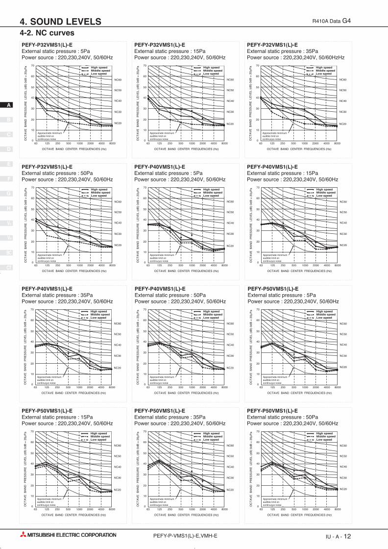
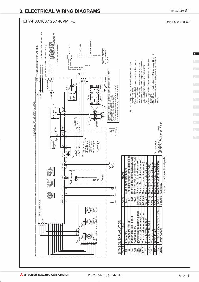
PEFY-P32VMS1(L)-EExternal static pressure : 5PaPower source : 220,230,240V, 50/60Hz
PEFY-P32VMS1(L)-EExternal static pressure : 15PaPower source : 220,230,240V, 50/60Hz
PEFY-P32VMS1(L)-EExternal static pressure : 35PaPower source : 220,230,240V, 50/60HzHz
PEFY-P32VMS1(L)-EExternal static pressure : 50PaPower source : 220,230,240V, 50/60Hz
PEFY-P40VMS1(L)-EExternal static pressure : 5PaPower source : 220,230,240V, 50/60Hz
PEFY-P40VMS1(L)-EExternal static pressure : 15PaPower source : 220,230,240V, 50/60Hz
PEFY-P40VMS1(L)-EExternal static pressure : 35PaPower source : 220,230,240V, 50/60Hz
PEFY-P40VMS1(L)-EExternal static pressure : 50PaPower source : 220,230,240V, 50/60Hz
PEFY-P50VMS1(L)-EExternal static pressure : 5PaPower source : 220,230,240V, 50/60Hz
PEFY-P50VMS1(L)-EExternal static pressure : 15PaPower source : 220,230,240V, 50/60Hz
PEFY-P50VMS1(L)-EExternal static pressure : 35PaPower source : 220,230,240V, 50/60Hz
PEFY-P50VMS1(L)-EExternal static pressure : 50PaPower source : 220,230,240V, 50/60Hz
Approximate minimum audible limit on continuous noise
70
60
50
40
30
20
63 125 250 500 1000 2000 4000 8000
10
0
NC60
NC50
NC40
NC30
NC20
Approximate minimum audible limit on continuous noiseO
CT
AV
E B
AN
D P
RE
SS
UR
E L
EV
EL
(dB
) 0d
B =
20μ
Pa
OCTAVE BAND CENTER FREQUENCIES (Hz)
High speed
Low speedMiddle speed
NC20
Approximate minimum audible limit on continuous noise
70
60
50
40
30
20
63 125 250 500 1000 2000 4000 8000
10
0
NC60
NC50
NC40
NC30
Approximate minimum audible limit on continuous noiseO
CT
AV
E B
AN
D P
RE
SS
UR
E L
EV
EL
(dB
) 0d
B =
20μ
Pa
OCTAVE BAND CENTER FREQUENCIES (Hz)
High speed
Low speedMiddle speed
Approximate minimum audible limit on continuous noise
70
60
50
40
30
20
63 125 250 500 1000 2000 4000 8000
10
0
NC60
NC50
NC40
NC30
NC20
Approximate minimum audible limit on continuous noiseO
CT
AV
E B
AN
D P
RE
SS
UR
E L
EV
EL
(dB
) 0d
B =
20μ
Pa
OCTAVE BAND CENTER FREQUENCIES (Hz)
High speed
Low speedMiddle speed
NC20
Approximate minimum audible limit on continuous noise
70
60
50
40
30
20
63 125 250 500 1000 2000 4000 8000
10
0
NC60
NC50
NC40
NC30
Approximate minimum audible limit on continuous noiseO
CT
AV
E B
AN
D P
RE
SS
UR
E L
EV
EL
(dB
) 0d
B =
20μ
Pa
OCTAVE BAND CENTER FREQUENCIES (Hz)
High speed
Low speedMiddle speed
Approximate minimum audible limit on continuous noise
70
60
50
40
30
20
63 125 250 500 1000 2000 4000 8000
10
0
NC60
NC50
NC40
NC30
NC20
Approximate minimum audible limit on continuous noiseO
CT
AV
E B
AN
D P
RE
SS
UR
E L
EV
EL
(dB
) 0d
B =
20μ
Pa
OCTAVE BAND CENTER FREQUENCIES (Hz)
High speed
Low speedMiddle speed
NC20
Approximate minimum audible limit on continuous noise
70
60
50
40
30
20
63 125 250 500 1000 2000 4000 8000
10
0
NC60
NC50
NC40
NC30
Approximate minimum audible limit on continuous noiseO
CT
AV
E B
AN
D P
RE
SS
UR
E L
EV
EL
(dB
) 0d
B =
20μ
Pa
OCTAVE BAND CENTER FREQUENCIES (Hz)
High speed
Low speedMiddle speed
Approximate minimum audible limit on continuous noise
70
60
50
40
30
20
63 125 250 500 1000 2000 4000 8000
10
0
NC60
NC50
NC40
NC30
NC20
Approximate minimum audible limit on continuous noiseO
CT
AV
E B
AN
D P
RE
SS
UR
E L
EV
EL
(dB
) 0d
B =
20μ
Pa
OCTAVE BAND CENTER FREQUENCIES (Hz)
High speed
Low speedMiddle speed
NC20
Approximate minimum audible limit on continuous noise
70
60
50
40
30
20
63 125 250 500 1000 2000 4000 8000
10
0
NC60
NC50
NC40
NC30
Approximate minimum audible limit on continuous noiseO
CT
AV
E B
AN
D P
RE
SS
UR
E L
EV
EL
(dB
) 0d
B =
20μ
Pa
OCTAVE BAND CENTER FREQUENCIES (Hz)
High speed
Low speedMiddle speed
Approximate minimum audible limit on continuous noise
70
60
50
40
30
20
63 125 250 500 1000 2000 4000 8000
10
0
NC60
NC50
NC40
NC30
NC20
Approximate minimum audible limit on continuous noiseO
CT
AV
E B
AN
D P
RE
SS
UR
E L
EV
EL
(dB
) 0d
B =
20μ
Pa
OCTAVE BAND CENTER FREQUENCIES (Hz)
High speed
Low speedMiddle speed
BC
CT
V-B
V-A
H
G
F
E
D
B
C
A
IU - A - 12PEFY-P-VMS1(L)-E,VMH-E
R410A Data G4
4-2. NC curves4. SOUND LEVELS
01_PEFY-VML,VMR,VMS1,VMH.qx:01_PEFY-VML,VMR,VMS1,VMH.qx 25/4/08 14:43 Page 12

PEFY-P63VMS1(L)-EExternal static pressure : 5PaPower source : 220,230,240V, 50/60Hz
PEFY-P63VMS1(L)-EExternal static pressure : 15PaPower source : 220,230,240V, 50/60Hz
PEFY-P63VMS1(L)-EExternal static pressure : 35PaPower source : 220,230,240V, 50/60Hz
PEFY-P63VMS1(L)-EExternal static pressure : 50PaPower source : 220,230,240V, 50/60Hz
NC20
Approximate minimum audible limit on continuous noise
70
60
50
40
30
20
63 125 250 500 1000 2000 4000 8000
10
0
NC60
NC50
NC40
NC30
Approximate minimum audible limit on continuous noiseO
CT
AV
E B
AN
D P
RE
SS
UR
E L
EV
EL
(dB
) 0d
B =
20μ
Pa
OCTAVE BAND CENTER FREQUENCIES (Hz)
High speed
Low speedMiddle speed
Approximate minimum audible limit on continuous noise
70
60
50
40
30
20
63 125 250 500 1000 2000 4000 8000
10
0
NC60
NC50
NC40
NC30
NC20
Approximate minimum audible limit on continuous noiseO
CT
AV
E B
AN
D P
RE
SS
UR
E L
EV
EL
(dB
) 0d
B =
20μ
Pa
OCTAVE BAND CENTER FREQUENCIES (Hz)
High speed
Low speedMiddle speed
NC20
Approximate minimum audible limit on continuous noise
70
60
50
40
30
20
63 125 250 500 1000 2000 4000 8000
10
0
NC60
NC50
NC40
NC30
Approximate minimum audible limit on continuous noiseO
CT
AV
E B
AN
D P
RE
SS
UR
E L
EV
EL
(dB
) 0d
B =
20μ
Pa
OCTAVE BAND CENTER FREQUENCIES (Hz)
High speed
Low speedMiddle speed
BC
CT
V-B
V-A
H
G
F
E
D
B
C
A
IU - A - 13PEFY-P-VMS1(L)-E,VMH-E
R410A Data G4
4-2. NC curves4. SOUND LEVELS
01_PEFY-VML,VMR,VMS1,VMH.qx:01_PEFY-VML,VMR,VMS1,VMH.qx 25/4/08 14:43 Page 13

PEFY-P80VMH-EExternal static pressure : 50PaPower source : 220V, 50/60Hz
PEFY-P80VMH-EExternal static pressure : 100PaPower source : 220V, 50/60Hz
PEFY-P80VMH-EExternal static pressure : 200PaPower source : 220V, 50/60Hz
PEFY-P100,125,140VMH-EExternal static pressure : 50PaPower source : 220V, 50/60Hz
PEFY-P100,125,140VMH-EExternal static pressure : 100PaPower source : 220V, 50/60Hz
PEFY-P100,125,140VMH-EExternal static pressure : 200PaPower source : 220V, 50/60Hz
NC60
NC50
NC40
NC30
NC20
Approximate minimum audible limit on continuous noise
70
60
50
40
30
20
63 125 250 500 1000 2000 4000 8000
10
0
High speedLow speed
OC
TA
VE
BA
ND
PR
ES
SU
RE
LE
VE
L (d
B)
0dB
= 2
0μP
a
OCTAVE BAND CENTER FREQUENCIES (Hz)
NC60
NC50
NC40
NC30
NC20
Approximate minimum audible limit on continuous noise
70
60
50
40
30
20
63 125 250 500 1000 2000 4000 8000
10
0
High speedLow speed
OC
TA
VE
BA
ND
PR
ES
SU
RE
LE
VE
L (d
B)
0dB
= 2
0μP
a
OCTAVE BAND CENTER FREQUENCIES (Hz)
NC60
NC50
NC40
NC30
NC20
Approximate minimum audible limit on continuous noise
70
60
50
40
30
20
63 125 250 500 1000 2000 4000 8000
10
0
High speedLow speed
OC
TA
VE
BA
ND
PR
ES
SU
RE
LE
VE
L (d
B)
0dB
= 2
0μP
a
OCTAVE BAND CENTER FREQUENCIES (Hz)
NC60
NC50
NC40
NC30
NC20
Approximate minimum audible limit on continuous noise
70
60
50
40
30
20
63 125 250 500 1000 2000 4000 8000
10
0
High speedLow speed
OC
TA
VE
BA
ND
PR
ES
SU
RE
LE
VE
L (d
B)
0dB
= 2
0μP
a
OCTAVE BAND CENTER FREQUENCIES (Hz)
NC60
NC50
NC40
NC30
NC20
Approximate minimum audible limit on continuous noise
70
60
50
40
30
20
63 125 250 500 1000 2000 4000 8000
10
0
High speedLow speed
OC
TA
VE
BA
ND
PR
ES
SU
RE
LE
VE
L (d
B)
0dB
= 2
0μP
a
OCTAVE BAND CENTER FREQUENCIES (Hz)
NC20
NC60
NC50
NC40
NC30
Approximate minimum audible limit on continuous noise
70
60
50
40
30
20
63 125 250 500 1000 2000 4000 8000
10
0
High speedLow speed
OC
TA
VE
BA
ND
PR
ES
SU
RE
LE
VE
L (d
B)
0dB
= 2
0μP
a
OCTAVE BAND CENTER FREQUENCIES (Hz)
BC
CT
V-B
V-A
H
G
F
E
D
B
C
A
IU - A - 14PEFY-P-VMS1(L)-E,VMH-E
R410A Data G4
4-2. NC curves4. SOUND LEVELS
01_PEFY-VML,VMR,VMS1,VMH.qx:01_PEFY-VML,VMR,VMS1,VMH.qx 25/4/08 14:43 Page 14

PEFY-P80VMH-EExternal static pressure : 200PaPower source : 230,240V, 50/60Hz
PEFY-P80VMH-EExternal static pressure : 100PaPower source : 230,240V, 50/60Hz
PEFY-P80VMH-EExternal static pressure : 150PaPower source : 230,240V, 50/60Hz
NC60
NC50
NC40
NC30
NC20
Approximate minimum audible limit on continuous noise
70
60
50
40
30
20
63 125 250 500 1000 2000 4000 8000
10
0
High speedLow speed
OC
TA
VE
BA
ND
PR
ES
SU
RE
LE
VE
L (d
B)
0dB
= 2
0μP
a
OCTAVE BAND CENTER FREQUENCIES (Hz)
NC60
NC50
NC40
NC30
NC20
Approximate minimum audible limit on continuous noise
70
60
50
40
30
20
63 125 250 500 1000 2000 4000 8000
10
0
High speedLow speed
OC
TA
VE
BA
ND
PR
ES
SU
RE
LE
VE
L (d
B)
0dB
= 2
0μP
a
OCTAVE BAND CENTER FREQUENCIES (Hz)
NC60
NC50
NC40
NC30
NC20
Approximate minimum audible limit on continuous noise
70
60
50
40
30
20
63 125 250 500 1000 2000 4000 8000
10
0
High speedLow speed
OC
TA
VE
BA
ND
PR
ES
SU
RE
LE
VE
L (d
B)
0dB
= 2
0μP
a
OCTAVE BAND CENTER FREQUENCIES (Hz)
BC
CT
V-B
V-A
H
G
F
E
D
B
C
A
IU - A - 15PEFY-P-VMS1(L)-E,VMH-E
R410A Data G4
4-2. NC curves4. SOUND LEVELS
01_PEFY-VML,VMR,VMS1,VMH.qx:01_PEFY-VML,VMR,VMS1,VMH.qx 25/4/08 14:43 Page 15

PEFY-P100,125,140VMH-EExternal static pressure : 100PaPower source : 230,240V, 50/60Hz
PEFY-P100,125,140VMH-EExternal static pressure : 150PaPower source : 230,240V, 50/60Hz
PEFY-P100,125,140VMH-EExternal static pressure : 200PaPower source : 230,240V, 50/60Hz
NC60
NC50
NC40
NC30
NC20
Approximate minimum audible limit on continuous noise
70
60
50
40
30
20
63 125 250 500 1000 2000 4000 8000
10
0
High speedLow speed
OC
TA
VE
BA
ND
PR
ES
SU
RE
LE
VE
L (d
B)
0dB
= 2
0μP
a
OCTAVE BAND CENTER FREQUENCIES (Hz)
NC60
NC50
NC40
NC30
NC20
Approximate minimum audible limit on continuous noise
70
60
50
40
30
20
63 125 250 500 1000 2000 4000 8000
10
0
High speedLow speed
OC
TA
VE
BA
ND
PR
ES
SU
RE
LE
VE
L (d
B)
0dB
= 2
0μP
a
OCTAVE BAND CENTER FREQUENCIES (Hz)
NC60
NC50
NC40
NC30
NC20
Approximate minimum audible limit on continuous noise
70
60
50
40
30
20
63 125 250 500 1000 2000 4000 8000
10
0
High speedLow speed
OC
TA
VE
BA
ND
PR
ES
SU
RE
LE
VE
L (d
B)
0dB
= 2
0μP
a
OCTAVE BAND CENTER FREQUENCIES (Hz)
BC
CT
V-B
V-A
H
G
F
E
D
B
C
A
IU - A - 16PEFY-P-VMS1(L)-E,VMH-E
R410A Data G4
4-2. NC curves4. SOUND LEVELS
01_PEFY-VML,VMR,VMS1,VMH.qx:01_PEFY-VML,VMR,VMS1,VMH.qx 25/4/08 14:43 Page 16

PEFY-P15VMS1(L)-EExternal static pressure : 15Pa Power source : 220,230,240V, 50/60Hz
Suction : Back inletPEFY-P15VMS1(L)-EExternal static pressure : 5Pa Power source : 220,230,240V, 50/60Hz
Suction : Back inlet
Airflow rate (m3/min)
Sta
tic p
ress
ure
(Pa)
Airflow rate (m3/min)
Sta
tic p
ress
ure
(Pa)
0
5
10
15
20
25
30
35
40
4 5 6 7 8 90
5
10
15
20
25
30
35
40
4 5 6 7 8 9
High
Limit
Limit
Low
Middle
High
Low
Middle
BC
CT
V-B
V-A
H
G
F
E
D
B
C
A
IU - A - 17PEFY-P-VMS1(L)-E,VMH-E
R410A Data G4
4-3. Fan characteristics curves4. SOUND LEVELS
01_PEFY-VML,VMR,VMS1,VMH.qx:01_PEFY-VML,VMR,VMS1,VMH.qx 25/4/08 14:43 Page 17

PEFY-P15VMS1(L)-EExternal static pressure : 50Pa Power source : 220,230,240V, 50/60Hz
Suction : Back inletPEFY-P15VMS1(L)-EExternal static pressure : 35Pa Power source : 220,230,240V, 50/60Hz
Suction : Back inlet
PEFY-P20VMS1(L)-EExternal static pressure : 15Pa Power source : 220,230,240V, 50/60Hz
Suction : Back inletPEFY-P20VMS1(L)-EExternal static pressure : 5Pa Power source : 220,230,240V, 50/60Hz
Suction : Back inlet
PEFY-P20VMS1(L)-EExternal static pressure : 50Pa Power source : 220,230,240V, 50/60Hz
Suction : Back inletPEFY-P20VMS1(L)-EExternal static pressure : 35Pa Power source : 220,230,240V, 50/60Hz
Suction : Back inlet
Airflow rate (m3/min)
Sta
tic p
ress
ure
(Pa)
Airflow rate (m3/min)S
tatic
pre
ssur
e (P
a)
Airflow rate (m3/min)
Sta
tic p
ress
ure
(Pa)
Airflow rate (m3/min)
Sta
tic p
ress
ure
(Pa)
Airflow rate (m3/min)
Sta
tic p
ress
ure
(Pa)
Airflow rate (m3/min)
Sta
tic p
ress
ure
(Pa)
4 5 6 7 8 90
10
20
30
40
50
60
70
80
4 5 6 7 8 90
10
20
30
40
50
60
70
80
0
5
10
15
20
25
30
35
40
4 5 6 7 8 90
5
10
15
20
25
30
35
40
4 5 6 7 8 9
4 5 6 7 8 90
10
20
30
40
50
60
70
80
4 5 6 7 8 90
10
20
30
40
50
60
70
80
High
Limit
Low
Middle
High
Limit
Low
Middle
High
Limit
Limit
Low
Middle
High
Low
Middle
High
Limit
Low
Middle
High
Limit
Low
Middle
BC
CT
V-B
V-A
H
G
F
E
D
B
C
A
IU - A - 18PEFY-P-VMS1(L)-E,VMH-E
R410A Data G4
4-3. Fan characteristics curves4. SOUND LEVELS
01_PEFY-VML,VMR,VMS1,VMH.qx:01_PEFY-VML,VMR,VMS1,VMH.qx 25/4/08 14:43 Page 18
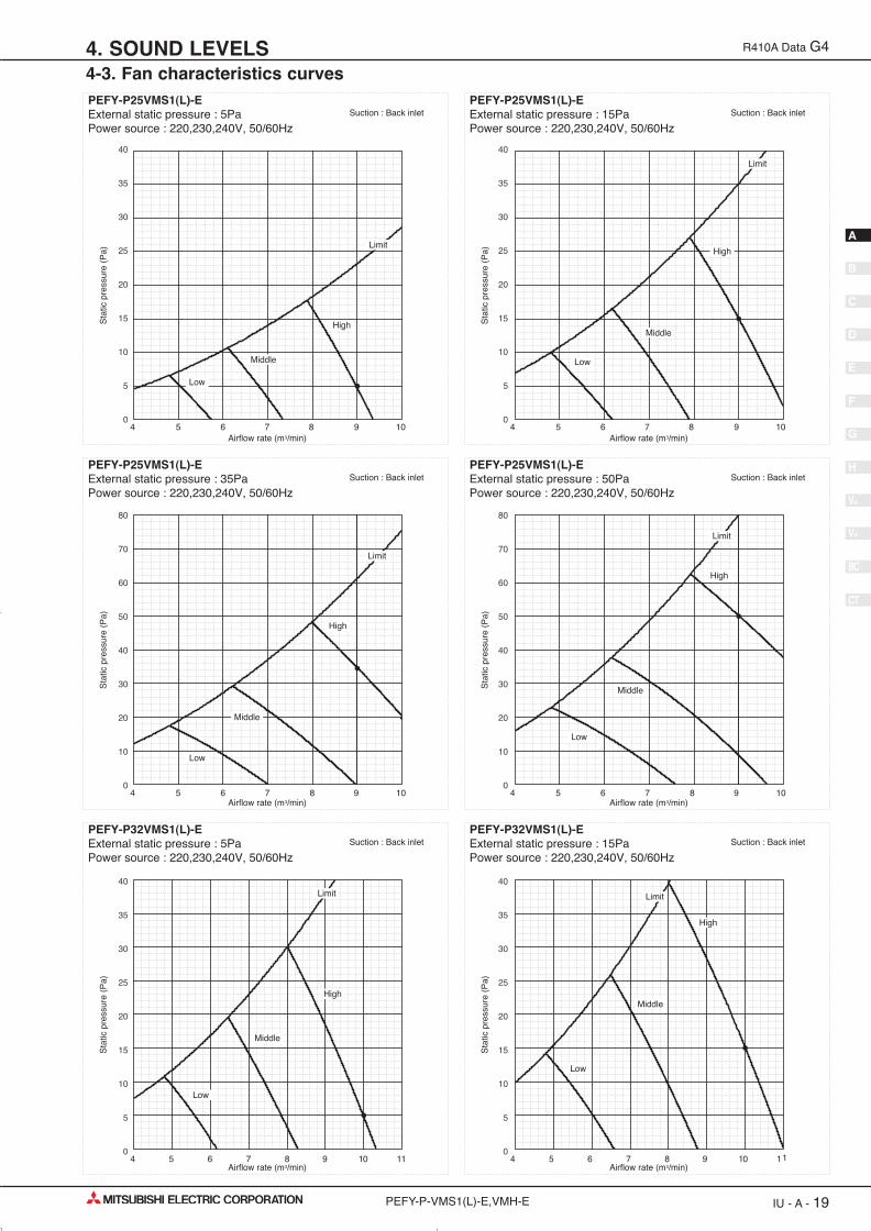
PEFY-P25VMS1(L)-EExternal static pressure : 5Pa Power source : 220,230,240V, 50/60Hz
Suction : Back inletPEFY-P25VMS1(L)-EExternal static pressure : 15Pa Power source : 220,230,240V, 50/60Hz
Suction : Back inlet
PEFY-P25VMS1(L)-EExternal static pressure : 35Pa Power source : 220,230,240V, 50/60Hz
Suction : Back inletPEFY-P25VMS1(L)-EExternal static pressure : 50Pa Power source : 220,230,240V, 50/60Hz
Suction : Back inlet
PEFY-P32VMS1(L)-EExternal static pressure : 15Pa Power source : 220,230,240V, 50/60Hz
Suction : Back inletPEFY-P32VMS1(L)-EExternal static pressure : 5Pa Power source : 220,230,240V, 50/60Hz
Suction : Back inlet
Airflow rate (m3/min)
Sta
tic p
ress
ure
(Pa)
Airflow rate (m3/min)
Sta
tic p
ress
ure
(Pa)
Airflow rate (m3/min)
Sta
tic p
ress
ure
(Pa)
Airflow rate (m3/min)
Sta
tic p
ress
ure
(Pa)
Airflow rate (m3/min)
Sta
tic p
ress
ure
(Pa)
Airflow rate (m3/min)
Sta
tic p
ress
ure
(Pa)
0
5
10
15
20
25
30
35
40
4 5 6 7 8 9 100
5
10
15
20
25
30
35
40
4 5 6 7 8 9 10
4 5 6 7 8 9 100
10
20
30
40
50
60
70
80
4 5 6 7 8 9 100
10
20
30
40
50
60
70
80
0
5
10
15
20
25
30
35
40
4 5 6 7 8 9 10 11 4 5 6 7 8 9 10 110
5
10
15
20
25
30
35
40
High
Limit
Low
Middle
High
Limit
Low
Middle
High
Limit
Low
Middle
High
Limit
Low
Middle
High
Limit
Low
Middle
High
Limit
Low
Middle
BC
CT
V-B
V-A
H
G
F
E
D
B
C
A
IU - A - 19PEFY-P-VMS1(L)-E,VMH-E
R410A Data G4
4-3. Fan characteristics curves4. SOUND LEVELS
01_PEFY-VML,VMR,VMS1,VMH.qx:01_PEFY-VML,VMR,VMS1,VMH.qx 25/4/08 14:43 Page 19

PEFY-P32VMS(L)-EExternal static pressure : 50Pa Power source : 220,230,240V, 50/60Hz
Suction : Back inletPEFY-P32VMS1(L)-EExternal static pressure : 35Pa Power source : 220,230,240V, 50/60Hz
Suction : Back inlet
PEFY-P40VMS1(L)-EExternal static pressure : 50Pa Power source : 220,230,240V, 50/60Hz
Suction : Back inletPEFY-P40VMS1(L)-EExternal static pressure : 35Pa Power source : 220,230,240V, 50/60Hz
Suction : Back inlet
PEFY-P40VMS1(L)-EExternal static pressure : 15Pa Power source : 220,230,240V, 50/60Hz
Suction : Back inletPEFY-P40VMS1(L)-EExternal static pressure : 5Pa Power source : 220,230,240V, 50/60Hz
Suction : Back inlet
Airflow rate (m3/min)
Sta
tic p
ress
ure
(Pa)
Airflow rate (m3/min)S
tatic
pre
ssur
e (P
a)
Airflow rate (m3/min)
Sta
tic p
ress
ure
(Pa)
Airflow rate (m3/min)
Sta
tic p
ress
ure
(Pa)
Airflow rate (m3/min)
Sta
tic p
ress
ure
(Pa)
Airflow rate (m3/min)
Sta
tic p
ress
ure
(Pa)
4 5 6 7 8 9 10 11 4 5 6 7 8 9 10 110
10
20
30
40
50
60
70
80
0
10
20
30
40
50
60
70
80
6 7 8 9 10 11 12 13 6 7 8 9 10 11 12 13
0
5
10
15
20
25
30
35
40
6 7 8 9 10 11 12 130
5
10
15
20
25
30
35
40
6 7 8 9 10 11 12 13
0
10
20
30
40
50
60
70
80
0
10
20
30
40
50
60
70
80
High
Limit
Low
Middle
High
Limit
Low
Middle
High
Limit
Low
Middle
High
Limit
Low
Middle
High
Limit
Low
Middle
High
Limit
Low
Middle
BC
CT
V-B
V-A
H
G
F
E
D
B
C
A
IU - A - 20PEFY-P-VMS1(L)-E,VMH-E
R410A Data G4
4-3. Fan characteristics curves4. SOUND LEVELS
01_PEFY-VML,VMR,VMS1,VMH.qx:01_PEFY-VML,VMR,VMS1,VMH.qx 25/4/08 14:43 Page 20

PEFY-P50VMS1(L)-EExternal static pressure : 15Pa Power source : 220,230,240V, 50/60Hz
Suction : Back inletPEFY-P50VMS1(L)-EExternal static pressure : 5Pa Power source : 220,230,240V, 50/60Hz
Suction : Back inlet
PEFY-P50VMS1(L)-EExternal static pressure : 50Pa Power source : 220,230,240V, 50/60Hz
Suction : Back inletPEFY-P50VMS1(L)-EExternal static pressure : 35Pa Power source : 220,230,240V, 50/60Hz
Suction : Back inlet
PEFY-P63VMS1(L)-EExternal static pressure : 15Pa Power source : 220,230,240V, 50/60Hz
Suction : Back inletPEFY-P63VMS1(L)-EExternal static pressure : 5Pa Power source : 220,230,240V, 50/60Hz
Suction : Back inlet
Airflow rate (m3/min)
Sta
tic p
ress
ure
(Pa)
Airflow rate (m3/min)
Sta
tic p
ress
ure
(Pa)
Airflow rate (m3/min)
Sta
tic p
ress
ure
(Pa)
Airflow rate (m3/min)
Sta
tic p
ress
ure
(Pa)
Airflow rate (m3/min)
Sta
tic p
ress
ure
(Pa)
Airflow rate (m3/min)
Sta
tic p
ress
ure
(Pa)
0
5
10
15
20
25
30
35
40
7 8 9 10 11 12 13 14 150
5
10
15
20
25
30
35
40
7 8 9 10 11 12 13 14 15
7 8 9 10 11 12 13 14 150
10
20
30
40
50
60
70
80
7 8 9 10 11 12 13 14 150
10
20
30
40
50
60
70
80
0
5
10
15
20
25
30
35
40
9 10 11 12 13 14 15 16 17 18 19 200
5
10
15
20
25
30
35
40
9 10 11 12 13 14 15 16 17 18 19 20
High
Limit
Low
Middle
High
Limit
Low
Middle
High
Limit
Low
Middle
High
Limit
Low
Middle
High
Limit
Low
Middle
High
Limit
Low
Middle
BC
CT
V-B
V-A
H
G
F
E
D
B
C
A
IU - A - 21PEFY-P-VMS1(L)-E,VMH-E
R410A Data G4
4-3. Fan characteristics curves4. SOUND LEVELS
01_PEFY-VML,VMR,VMS1,VMH.qx:01_PEFY-VML,VMR,VMS1,VMH.qx 25/4/08 14:43 Page 21

PEFY-P63VMS1(L)-EExternal static pressure : 50Pa Power source : 220,230,240V, 50/60Hz
Suction : Back inletPEFY-P63VMS1(L)-EExternal static pressure : 35Pa Power source : 220,230,240V, 50/60Hz
Suction : Back inlet
Airflow rate (m3/min)
Sta
tic p
ress
ure
(Pa)
Airflow rate (m3/min)S
tatic
pre
ssur
e (P
a)9 10 11 12 13 14 15 16 17 18 19 20
0
10
20
30
40
50
60
70
80
9 10 11 12 13 14 15 16 17 18 19 200
10
20
30
40
50
60
70
80
High
Limit
Low
Middle
High
Limit
Low
Middle
BC
CT
V-B
V-A
H
G
F
E
D
B
C
A
IU - A - 22PEFY-P-VMS1(L)-E,VMH-E
R410A Data G4
4-3. Fan characteristics curves4. SOUND LEVELS
01_PEFY-VML,VMR,VMS1,VMH.qx:01_PEFY-VML,VMR,VMS1,VMH.qx 25/4/08 14:43 Page 22

PEFY-P100,125VMH-EExternal static pressure : 100,150,200Pa Power source : 230,240V
Suction : Back inletPEFY-P100,125VMH-EExternal static pressure : 50,100,200Pa Power source : 220V
Suction : Back inlet
50Hz60Hz
50Hz60Hz
PEFY-P80VMH-EExternal static pressure : 100,150,200Pa Power source : 230,240V
Suction : Back inletPEFY-P80VMH-EExternal static pressure : 50,100,200Pa Power source : 220V
Suction : Back inlet
50Hz60Hz
50Hz60Hz
25 30 35 40 450
50
100
150
200
250 250
200
150
100
50
04540353025
2520150
50
100
150
200
250250
200
150
100
50
015 20 25
Sta
tic p
ress
ure
(Pa)
Sta
tic p
ress
ure
(Pa)
Airflow rate (m3/min) Airflow rate (m3/min)
Long-life filter
Highefficiency filter
Long-life filter
Highefficiency filter
Sta
tic p
ress
ure
(Pa)
Sta
tic p
ress
ure
(Pa)
Airflow rate (m3/min)Airflow rate (m 3/min)
Long-life filter
Highefficiency filter
Long-life filter
Highefficiency filter
High(200) High(200)
High(100)
High(100)
High(150)
High(50)Low Low
High(200) High(200)
High(100)
High(150)
High(100)
Low Low
High(50)
BC
CT
V-B
V-A
H
G
F
E
D
B
C
A
IU - A - 23PEFY-P-VMS1(L)-E,VMH-E
R410A Data G4
4-3. Fan characteristics curves4. SOUND LEVELS
01_PEFY-VML,VMR,VMS1,VMH.qx:01_PEFY-VML,VMR,VMS1,VMH.qx 25/4/08 14:43 Page 23
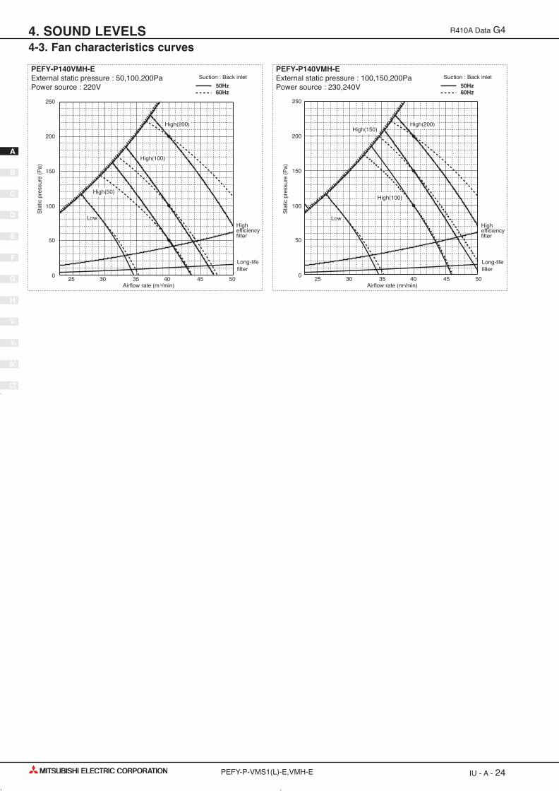
PEFY-P140VMH-EExternal static pressure : 100,150,200Pa Power source : 230,240V
Suction : Back inletPEFY-P140VMH-EExternal static pressure : 50,100,200Pa Power source : 220V
Suction : Back inlet
50Hz60Hz
50Hz60Hz
5025 30 35 40 450
50
100
150
200
250
25 30 35 40 45 500
50
100
150
200
250
Long-life filter
High efficiency filter
High efficiency filter
Long-life filter
Sta
tic p
ress
ure
(Pa)
Sta
tic p
ress
ure
(Pa)
Airflow rate (m3/min)Airflow rate (m 3/min)
High(200) High(200)
High(100)
High(100)
High(150)
High(50)
Low Low
BC
CT
V-B
V-A
H
G
F
E
D
B
C
A
IU - A - 24PEFY-P-VMS1(L)-E,VMH-E
R410A Data G4
4-3. Fan characteristics curves4. SOUND LEVELS
01_PEFY-VML,VMR,VMS1,VMH.qx:01_PEFY-VML,VMR,VMS1,VMH.qx 25/4/08 14:43 Page 24

■ Optional parts line up for the Indoor unitLong-life fi lter Filter box Drain pump
PEFY-P80VMH-E PEFY-P100,125,140VMH-E
PAC-KE88LAFPAC-KE89LAF
PAC-KE80TB-FPAC-KE140TB-F
PAC-KE04DM-FPAC-KE04DM-F
● PEFY-P-VMH-E
Long-life filter PAC-KE-LAF
Filter box PAC-KE-TB-F
PEFY-P-VMH-E
Drain pumpPAC-KE04DM-F
Long-life filter PAC-KE-LAF
BC
CT
V-B
V-A
H
G
F
E
D
B
C
A
IU - A - 25PEFY-P-VMS1(L)-E,VMH-E
5. Optional parts for PEFY-P-VMS1L-E,VMH-E R410A Data G4
01_PEFY-VML,VMR,VMS1,VMH.qx:01_PEFY-VML,VMR,VMS1,VMH.qx 25/4/08 14:43 Page 25

■ Optional parts line up for the Indoor unitLong-life fi lter Filter box Drain pump
PEFY-P80VMH-E PEFY-P100,125,140VMH-E
PAC-KE88LAFPAC-KE89LAF
PAC-KE80TB-FPAC-KE140TB-F
PAC-KE04DM-FPAC-KE04DM-F
■ Long-life fi lter PAC-KE-LAF and fi lter box PAC-KE-TB-F for PEFY-P-VMH-ELife span: 2,500 hr (Dust concentration 0.15mg/m3)
*. The actual dust situation affects the filter lif e span, which should be considered at the applying site.
Material: Synthetic fi ber unwoven cloth filter Static pressure loss is referred to 3-3 “Fan characteriastics curves”.Long-life filter should be used together with fi lter box PAC-KE-TB-F.
PAC-KE-LAF
Item PAC-KE86LAF PAC-KE88LAF PAC-KE89LAF PAC-KE85LAF
Quantity 2 3 3 2
Shape
(298X300) (298X300) (298X300) (411X600)
■ Drain pump PAC-KE04DM-FIf drain water can not flow out the Indoor unit by gravity and gradient, a Drain-pump for draining is needed.Drain pump PAC-KE04DM-F can pump water up to 550mm high from the drain pan.
Item 1 Drain pump ass'y 2 Separator 3 Rubber plug 4 Connector 5 Dummy connector
Quantity 1 1 2 1 1
Shape
Drain sensor
Drain socket
Item 6 Rubber bushing 7 Band 8 PTT screw 4X10 9 Fixing plate 0 Installation manual
Quantity 1 2 6+1 (spare) 1 1
Shape
Detailed installation information should be referred to its Installation Manual ( )
Detailed installation information should be referred to its Installation Manual ( )
PAC-KE-TB-F
Item 1 Screw 2 Filter box 3 Installation manual
Quantity 10/12* 1 1
Shape
*PAC-KE250TB has 12 pieces of screw.
Detailed installation information should be referred to its Installation Manual ( , )
WT03312X02
WT02574X04
WT03018X02 WT03019X02
BC
CT
V-B
V-A
H
G
F
E
D
B
C
A
IU - A - 26PEFY-P-VMS1(L)-E,VMH-E
R410A Data G45. Optional parts for PEFY-P-VMS1L-E,VMH-E
01_PEFY-VML,VMR,VMS1,VMH.qx:01_PEFY-VML,VMR,VMS1,VMH.qx 25/4/08 14:43 Page 26

■ Optional parts line up for the Indoor unitDrain pump
PEFY-P15VMS1L-E PAC-KE07DM-E PEFY-P20VMS1L-E PAC-KE07DM-E PEFY-P25VMS1L-E PAC-KE07DM-E PEFY-P32VMS1L-E PAC-KE07DM-E PEFY-P40VMS1L-E PAC-KE07DM-E PEFY-P50VMS1L-E PAC-KE07DM-E PEFY-P63VMS1L-E PAC-KE07DM-E
■ Drain pump PAC-KE07DM-EDrain pump is an optional part for VMS1L, and a standard for VMS1. When using drain pump, PAC-KE07DM-E (mounting type) is required.
Item 1 Drain pump 2 Attachment 3 Drain hose 1 4 Pipe cover 1 5 Pipe cover 2
Quantity 1 1 1
(385mm) (255mm) (200mm)
(100mm)
(380mm)(175mm)
1 1
Shape
Item 6 Hose band 7 Screw 8 Clamp 9 Ferrite clamp 0 Band 1
Quantity 1 3 3 1 2
Shape
Item Pipe cover 3Drain hose 2 Band 2
Quantity 1 1 6
Shape
131211
BC
CT
V-B
V-A
H
G
F
E
D
B
C
A
IU - A - 27PEFY-P-VMS1(L)-E,VMH-E
5. Optional parts for PEFY-P-VMS1L-E,VMH-E R410A Data G4
01_PEFY-VML,VMR,VMS1,VMH.qx:01_PEFY-VML,VMR,VMS1,VMH.qx 25/4/08 14:43 Page 27

PEFY-P-VMS1(L)-E,VMH-E IU - A - 28
A
C
B
D
E
F
G
H
V-A
V-B
CT
BC
01_PEFY-VML,VMR,VMS1,VMH.qx:01_PEFY-VML,VMR,VMS1,VMH.qx 28/4/08 12:38 Page 28