00_ZF_man_GT_33100 DESAN 1_AL06759
98
Maintenance and Operating Manual for Gearbox type ZF W Project: DESAN 1 - KH 850 Gearbox Model ZF W33100 NR + PTO 3 Shipyard DESAN NB 21 KH Size KH 850 Order Number AL06759 Mod. 09.2008
-
Upload
abuzer1981 -
Category
Documents
-
view
34 -
download
1
Transcript of 00_ZF_man_GT_33100 DESAN 1_AL06759
Maintenanceand OperatingManual for Gearbox type ZF W
Project:DESAN 1 - KH 850
Gearbox Model ZF W33100 NR + PTO 3Shipyard DESAN
NB 21KH Size KH 850
Order Number AL06759
Mod. 09.2008

After Receipt of Equipment
Section 1
Date
ZF Padova S.p.A.Via Penghe, 48 – I-35030 Caselle di Selvazzano (PD) – ITALY
Tel. +39-049 8299-311 – Fax +39-049 8299-550 – www.ZF-Marine.com3
Date
ZF Padova S.p.A.Via Penghe, 48 – I-35030 Caselle di Selvazzano (PD) – ITALY
Tel. +39-049 8299-311 – Fax +39-049 8299-550 – www.ZF-Marine.com
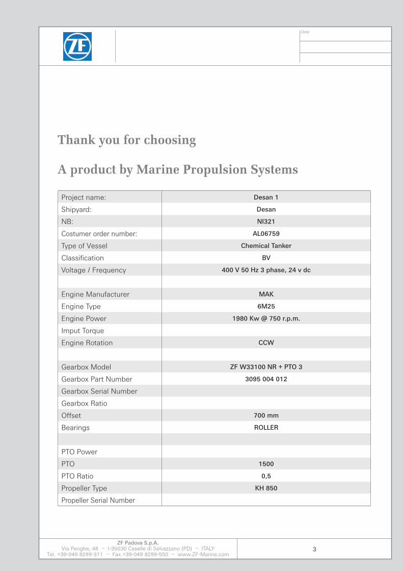
Thank you for choosing
A product by Marine Propulsion Systems
Project name: Desan 1
Shipyard: Desan
NB: NI321
Costumer order number: AL06759
Type of Vessel Chemical Tanker
Classification BV
Voltage / Frequency 400 V 50 Hz 3 phase, 24 v dc
Engine Manufacturer MAK
Engine Type 6M25
Engine Power 1980 Kw @ 750 r.p.m.
Imput Torque
Engine Rotation CCW
Gearbox Model ZF W33100 NR + PTO 3
Gearbox Part Number 3095 004 012
Gearbox Serial Number
Gearbox Ratio
Offset 700 mm
Bearings ROLLER
PTO Power
PTO 1500
PTO Ratio 0,5
Propeller Type KH 850
Propeller Serial Number
3
Date
ZF Padova S.p.A.Via Penghe, 48 – I-35030 Caselle di Selvazzano (PD) – ITALY
Tel. +39-049 8299-311 – Fax +39-049 8299-550 – www.ZF-Marine.com4
5
General Index
Date
ZF Padova S.p.A.Via Penghe, 48 – I-35030 Caselle di Selvazzano (PD) – ITALY
Tel. +39-049 8299-311 – Fax +39-049 8299-550 – www.ZF-Marine.com
The manual consists of 11 sections as follows:
Section 1: TECHNICAL DATA Page 7
Section 2: MAINTENANCE AND OPERATION MANUAL Page 13
Section 3: AFTER RECEIPT OF EQUIPMENT Page 17
Section 4: OPERATING NOTES Page 23
Section 5: WORKING PRINCIPLES Page 27
Section 6: INSTALLATION DESCRIPTION Page 41
Section 7: STARTING OPERATION Page 53
Section 8: EMERGENCY OPERATION Page 73
Section 9: MAINTENANCE Page 79
Section 10: TROUBLESHOOTING REMEDIES Page 91
Section 11: SERVICE CENTERS Page 97
Section 12: APPENDIX Page 103
Appendix 1: Recommended Oils
Appendix 2: Bearing Calculation
Appendix 3: Thermal growth
Appendix 4: Spare parts list
Appendix 5: Torsional Vibration Calculation
Appendix 6: Ortlinghaus discs
Appendix 7: Mahle filters
Appendix 8: Kracht pumps
Appendix 9: Hs cooler
Appendix 10: Gestra valves
Appendix 11: Drawings
5

Date
ZF Padova S.p.A.Via Penghe, 48 – I-35030 Caselle di Selvazzano (PD) – ITALY
Tel. +39-049 8299-311 – Fax +39-049 8299-550 – www.ZF-Marine.com6
Remarks
_________________________________________________________________________________________________
_________________________________________________________________________________________________
_________________________________________________________________________________________________
_________________________________________________________________________________________________
_________________________________________________________________________________________________
_________________________________________________________________________________________________
_________________________________________________________________________________________________
_________________________________________________________________________________________________

Section 1


Date
ZF Padova S.p.A.Via Penghe, 48 – I-35030 Caselle di Selvazzano (PD) – ITALY
Tel. +39-049 8299-311 – Fax +39-049 8299-550 – www.ZF-Marine.com9
1.1 IDENTIFICATION
The identification plate is fixed on the marine gearbox. The guarantee ceases to be valid if this plate is tampered with or removed. Every time an assistance centre is contacted the details on the plate must be reported.
Technical data
Section 1
SERIAL No RATIO
TYPE
OIL TYPE
OIL CHANGE: after first 250 hours of operation and every2000 hours or 12 months, wichever occurs first.
CHECK OIL LEVEL WEEKLY
OILCAPACITY (z)
CLUTCH OIL PRESSURE(bar)
CUSTOMER No MASS DRY (Kg)PART LIST No
ContinousMediumLightPleasure
Fig.1.1
Date
ZF Padova S.p.A.Via Penghe, 48 – I-35030 Caselle di Selvazzano (PD) – ITALY
Tel. +39-049 8299-311 – Fax +39-049 8299-550 – www.ZF-Marine.com10
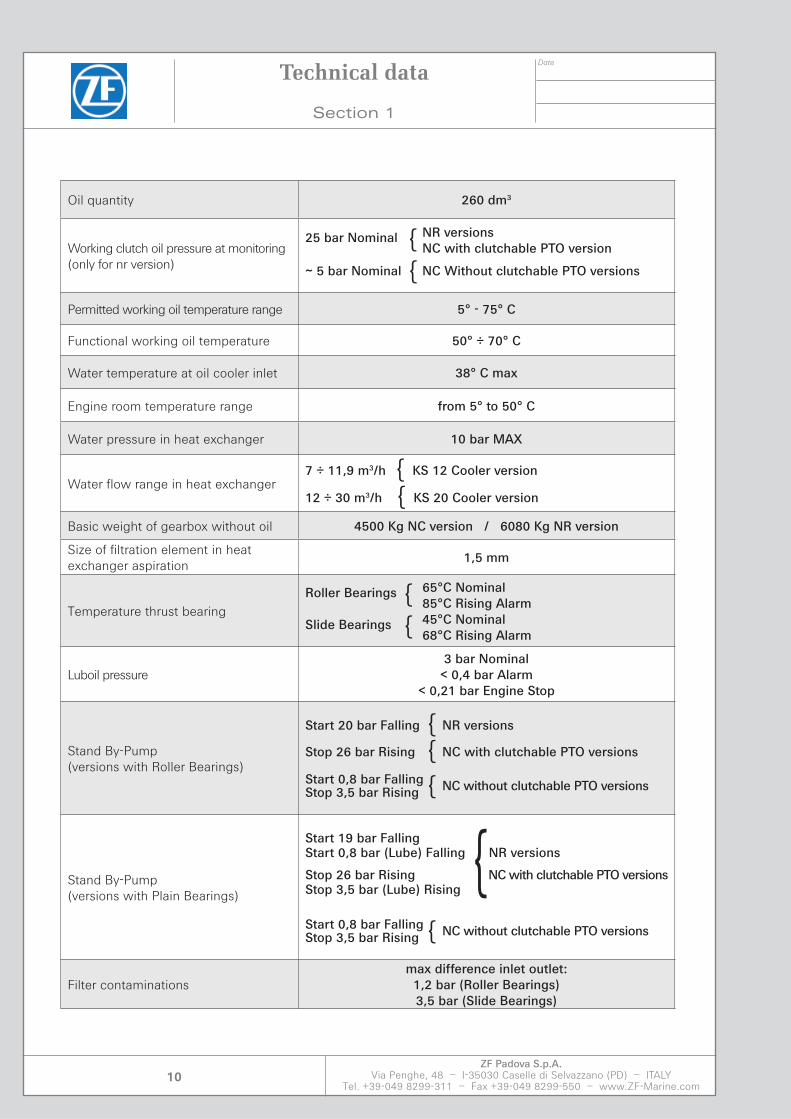
Oil quantity 260 dm3
Working clutch oil pressure at monitoring(only for nr version)
25 bar Nominal { NR versions NC with clutchable PTO version
~ 5 bar Nominal { NC Without clutchable PTO versions
Permitted working oil temperature range 5° - 75° C
Functional working oil temperature 50° ÷ 70° C
Water temperature at oil cooler inlet 38° C max
Engine room temperature range from 5° to 50° C
Water pressure in heat exchanger 10 bar MAX
Water flow range in heat exchanger 7 ÷ 11,9 m3/h { KS 12 Cooler version
12 ÷ 30 m3/h { KS 20 Cooler version
Basic weight of gearbox without oil 4500 Kg NC version / 6080 Kg NR version
Size of filtration element in heatexchanger aspiration
1,5 mm
Temperature thrust bearingRoller Bearings { 65°C Nominal 85°C Rising Alarm
Slide Bearings { 45°C Nominal 68°C Rising Alarm
Luboil pressure 3 bar Nominal
< 0,4 bar Alarm< 0,21 bar Engine Stop
Stand By-Pump(versions with Roller Bearings)
Start 20 bar Falling { NR versions
Stop 26 bar Rising { NC with clutchable PTO versions
Start 0,8 bar Falling { NC without clutchable PTO versionsStop 3,5 bar Rising
Stand By-Pump(versions with Plain Bearings)
Start 19 bar Falling Start 0,8 bar (Lube) Falling NR versions
Stop 26 bar Rising {NC with clutchable PTO versionsStop 3,5 bar (Lube) Rising
Start 0,8 bar Falling { NC without clutchable PTO versionsStop 3,5 bar Rising
Filter contaminations max difference inlet outlet:
1,2 bar (Roller Bearings)3,5 bar (Slide Bearings)
Technical data
Section 1
Date
ZF Padova S.p.A.Via Penghe, 48 – I-35030 Caselle di Selvazzano (PD) – ITALY
Tel. +39-049 8299-311 – Fax +39-049 8299-550 – www.ZF-Marine.com11
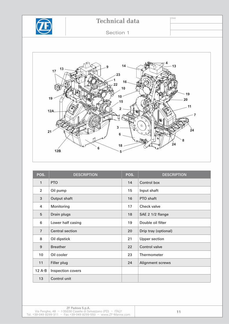
POS. DESCRIPTION POS. DESCRIPTION
1 PTO 14 Control box
2 Oil pump 15 Input shaft
3 Output shaft 16 PTO shaft
4 Monitoring 17 Check valve
5 Drain plugs 18 SAE 2 1/2 flange
6 Lower half casing 19 Double oil filter
7 Central section 20 Drip tray (optional)
8 Oil dipstick 21 Upper section
9 Breather 22 Control valve
10 Oil cooler 23 Thermometer
11 Filler plug 24 Alignment screws
12 A-B Inspection covers
13 Control unit
Technical data
Section 1
13
19
20
11
7
414
16
10
2
3
6
18
5
8
6
15
10
1
91317
19
12A
12B
22
21
23
24
24

Date
ZF Padova S.p.A.Via Penghe, 48 – I-35030 Caselle di Selvazzano (PD) – ITALY
Tel. +39-049 8299-311 – Fax +39-049 8299-550 – www.ZF-Marine.com12
Remarks
_________________________________________________________________________________________________
_________________________________________________________________________________________________
_________________________________________________________________________________________________
_________________________________________________________________________________________________
_________________________________________________________________________________________________
_________________________________________________________________________________________________
_________________________________________________________________________________________________
_________________________________________________________________________________________________
Technical data
Section 1

Section 2


Date
ZF Padova S.p.A.Via Penghe, 48 – I-35030 Caselle di Selvazzano (PD) – ITALY
Tel. +39-049 8299-311 – Fax +39-049 8299-550 – www.ZF-Marine.com15
Maintenance and Operation Manual
Purpose of this manual:
The following manual contains the information required for installers and users of ZF Ma-rine Propulsion System’s equipment. Users may include ship’s staff, shipping company superintendents, land based support staff, shipbuilders and dry-dock supervisory staff.
This manual is intended to provide the information necessary for the safe installation, onboard operation and routine ship’s maintenance. The manual also contains spare parts ordering information.
It is appreciated by ZF Marine Propulsion Systems that regional laws, insurance provi-sions, shipping company standards and shipyard regulations as well as ship’s design spe-cific considerations, etc, may result in the necessity to modify, or change the technology, practices and procedures described herein. Please be advised, however, that any modi-fication, or change of technology, practices and/or procedures may invalidate the manu-facturer warranty, unless prior written agreement has been received, from ZF Marine.
Instructions within this manual include specific symbols to be carefully observed:
: danger to life and limb
: danger to product and/or overall plant
: danger to other aspects
: attention to notes
Maintenance and Operation Manual
Section 2

Date
ZF Padova S.p.A.Via Penghe, 48 – I-35030 Caselle di Selvazzano (PD) – ITALY
Tel. +39-049 8299-311 – Fax +39-049 8299-550 – www.ZF-Marine.com16
Limitations of liability: end user, customer andmanufacturer responsibility:
Installation and Operation of the equipment, including unauthorized modifications, out-side the parameters described in this manual, may result in irreparable damage to, and/or malfunction of the equipment. Such actions may result in invalidation and rejection of existing warranty and any warranty claims, solely at the manufacturers discretion.
Installation, maintenance and/or modification work shall only be performed by certified ZF Marine service engineers or ZF Marine qualified service facilities. Please refer to the ZF Marine service organizations listed inside this manual or visit the Support Section of our web site at www.ZF-Marine.com
NOTE RELATING TO REPAIR WORK:
Due to continuing development of our products, manufacturing technology and proce-dures future repair work may require the application of work practices, test or adjustment data that are not covered by this manual at the time of issue. We therefore recommend that repair work carried out on your ZF product is performed only by skilled technicians who have undergone practical and theoretical skills training. ZF training includes re-fresher and assessment courses, and are conducted at approved ZF training centers.
The ZF group has installed a network of fully staffed Sales and Service Organization Cen-ters, (SSO’s), at strategic locations throughout the world so that our customers receive field support close to their geographical location. Repair work carried out at ZF SSO’s will be guaranteed in accordance with the prevailing contractual conditions.
NOTE RELATING TO DAMAGE:
Damages resulting from work performed by non-ZF personnel and which is deemed by ZF to have been conducted in an improper manner are, in their entirety, excluded from the ZF contractual guarantee. This includes all follow-up remedial work, the costs thereof, consequential damages such as loss of vessel operational time and any other associated loss of revenue including any and all third party liabilities.
ZF Padova S.p.A.Via Penghe, 48I-35030 Caselle di Selvazzano (PD)ITALYTel. +39-049 8299-311Fax +39-049 8299-550www.ZF-Marine.com
Maintenance and Operation Manual
Section 2

Section 3

Date
ZF Padova S.p.A.Via Penghe, 48 – I-35030 Caselle di Selvazzano (PD) – ITALY
Tel. +39-049 8299-311 – Fax +39-049 8299-550 – www.ZF-Marine.com19
After Receipt of Equipment:
Handling and Storage.
3.1 GENERAL:
The material has been shipped in good condition, protected against mechanical damage and corrosion by appropriate packaging. The consignee/shipyard shall inspect the mate-rial upon delivery and make sure that all items have been delivered as shown on the trans-port documents no item has suffered any damage during transportation and handling all parts are free of corrosion.
After Receipt of Equipment
Section 3
Date
ZF Padova S.p.A.Via Penghe, 48 – I-35030 Caselle di Selvazzano (PD) – ITALY
Tel. +39-049 8299-311 – Fax +39-049 8299-550 – www.ZF-Marine.com20
3.2 UPON RECEIPT OF THE GOODS:
NOTE:
Before ZF marine gears are supplied to our customers, they are tested on test rigs/bench-es. During this test, every function, oil pressures, temperature and noise level are checked thoroughly and recorded. After the test run, the inside of the transmission is flushed with oil to preserve it. The transmission can then be stored in a dry place for up to 12 months without the need for further special measures.
Any necessary preservation of the outside of the transmission depends on storage condi-tions and should be undertaken by the customer. Preservation measures for long storage periods must be specified when ordering.
All shipping crates and packages must immediately undergo an inspection for external damage. If any damage is noticed, the damaged locations must be photographed and together with a notification letter sent to the ZF Marine contract administration depart-ment.
Please note that failure to do so promptly may invalidate or delay any insurance claims filed on behalf of either shipyard and/or ZF Marine and shall absolve ZF Marine of any responsibility for damages that might be found during the installation process.
After unpacking of the equipment, the scope of supply shall be carefully checked against the packing list and the technical specification of the system. Please contact the ZF Marine contract administration department in the event that any part(s) are missing for a speedy replacement.
Once the consignee/shipyard has accepted the delivery of the goods, the consignee/shipyard is responsible for ensuring that the goods are stored in a covered storage site to prevent mechanical damage to and/or corrosion of the goods. No dirt, dust, humidity or any other matter shall be allowed to penetrate into the mechanical devices and/or electric or electronic components.
After Receipt of Equipment
Section 3
Date
ZF Padova S.p.A.Via Penghe, 48 – I-35030 Caselle di Selvazzano (PD) – ITALY
Tel. +39-049 8299-311 – Fax +39-049 8299-550 – www.ZF-Marine.com21
3.3 NOTES ON HANDLING AND STORAGE:
When handling the equipment make sure the carrying capacity of the crane is adequate.
• Use exclusively approved handling equipment.
• Attach the handling equipment carefully to the suspension devices indicated in the in-stallation drawing.
Lift the gearbox carefully and without jolts.
• Move the gearbox in its mounting position only and avoid jolts and shocks.
• Put the gearbox down carefully and without jolts.
• When lifting the gearbox make sure that the handling elements do not cause damage to attachment parts.
• Store the gearboxes in dry and moderately heated rooms only.
• Store the gearboxes only in their intended mounting position.
• Make sure that the gearboxes are only set down in the area of the alignment bolts as indicated in the installation drawing.
• Make sure that gearboxes put on the ground rest immovably and are not exposed to external forces.
• Remove blank flanges and plugs closing off oil and cooling water connections only after gearbox mounting has been completed.
Make sure that dirt, foreign substances and water cannot enter the gearbox interior.
• Note: ZF will dispose of any packing material supplied with the gearboxes when this is returned to the factory free of charge.
After Receipt of Equipment
Section 3
Date
ZF Padova S.p.A.Via Penghe, 48 – I-35030 Caselle di Selvazzano (PD) – ITALY
Tel. +39-049 8299-311 – Fax +39-049 8299-550 – www.ZF-Marine.com22
3.4 CORROSION PREVENTION:
Gearboxes supplied by ZF are not filled with oil. The interior of the gearboxes has been protected against corrosion by oil flushing.
The surfaces of external flanges, shaft ends and flange attachment faces are protected against corrosion.
The gearboxes are protected against corrosion for a period of 12 months provided the instructions given under point 3.2 are carefully observed.
If the gearboxes are turned prior to commissioning and only taken into service at a much later date, suitable corrosion preventive measures must in any case be taken. For further details in this connection, please contact the ZF Service Department.
FOLLOWING INSTRUCTIONS MUST BE ADHERED TO!CUSTOMER IS RESPONSIBLE FOR STORAGE/ PROTECTION.
CORROSION PROTECTION MUST IMMEDIATELY BE RENEWED.
CORROSION PROTECTION MUST BE RENEWED AT MONTHLY INTERVALS.
MINOR CORROSION SPOTS MUST BE POLISHED AND NEW PROTECTION APPLIED.
After Receipt of Equipment
Section 3

Section 4

Date
ZF Padova S.p.A.Via Penghe, 48 – I-35030 Caselle di Selvazzano (PD) – ITALY
Tel. +39-049 8299-311 – Fax +39-049 8299-550 – www.ZF-Marine.com25
Operating notes
Section 4
4.1 SAFETY NOTES
• The gear unit is constructed in accordance with the state of the art and is reliable in the condition as shipped. Unauthorized modifications which impair its reliability are NOT permissible. This also applies to guards which are fitted as protection against accidental contact.
• The gear unit may only be used and operated within the scope of the conditions speci-fied in the contract of performance and supply.
• The customer has to ensure that the persons entrusted with installation, operation and maintenance have read and understood the Operating Instructions and observe them in all respects in order to:
– Prevent hazard to life and limb of the user and third parties
– Ensure the reliability of the gear unit
and
– Prevent failure and evironmental pollution due to incorrect handling.
• The relevant regulations concerning industrial safery and pollution control should be observed during handling, installation, operation, and care and maintenance.
• The gear unit may only be operated, serviced and repaired by authorized, trained and properly instructed personnel.
• Cleaning with a high-pressure cleaning device is not permissible.
• All work should be carried out with care with the safety aspect in mind.
• All work on the gear unit may only be carried out when it is stationary. The drive unit must be secured to prevent accidental startup (e.g. by locking the key
switch or by removing the fuses in the power supply). A notice should be displayed at the switch-on point stating that work is in progress on the gear unit.

Date
ZF Padova S.p.A.Via Penghe, 48 – I-35030 Caselle di Selvazzano (PD) – ITALY
Tel. +39-049 8299-311 – Fax +39-049 8299-550 – www.ZF-Marine.com26
• On the occasion of oil changes, the old oil should be collected in a suitable receptacle. Any pools of oil which have occurred should be removed at once with an oil binding agent.
Very dirty and oil-soaked cleaning rags should be kept in suitable containers. The oil, the oil binding agnt and the cleaning rags should be disposed of in accordance
with the relevant pollution control requirements.
• The drive unit should be shut off at once if changes in the gear unit are detected during operation, such as for example increased operating temperature or a change in gear unit noises.
• Rotating parts, such as couplings, gear wheels or belt drives must be protected by means of suitable guards to prevent accidental contact.
• During installation of the gear unit in units or systems, the manufacturer of the units or systems is obliged to incorporate the requirements notes and descriptions contained in these Operating Instructions in his own Operating Instructions.
• Notes affixed to gear units, such as for example rating plate, direction of rotation ar-rows, etc., must be observed. They must be kept free from paint and dirt. Missing plates must be replaced.
Working with naked flames and performing welding work in the vicinity of the gearbox and pipe openings are prohibited.
Make sure work is only performed when the equipment has been disconnected from the electrical supply system.
Operating notes
Section 4

Section 5


Date
ZF Padova S.p.A.Via Penghe, 48 – I-35030 Caselle di Selvazzano (PD) – ITALY
Tel. +39-049 8299-311 – Fax +39-049 8299-550 – www.ZF-Marine.com29
Working principles
Section 5
Working principles
5.1 WORKING PRINCIPLES
The main functions of the marine gear box are the following: to couple the engine with the propeller axle and reduce the number of propeller revolutions, to stop propeller axle motion (neutral).
Date
ZF Padova S.p.A.Via Penghe, 48 – I-35030 Caselle di Selvazzano (PD) – ITALY
Tel. +39-049 8299-311 – Fax +39-049 8299-550 – www.ZF-Marine.com30
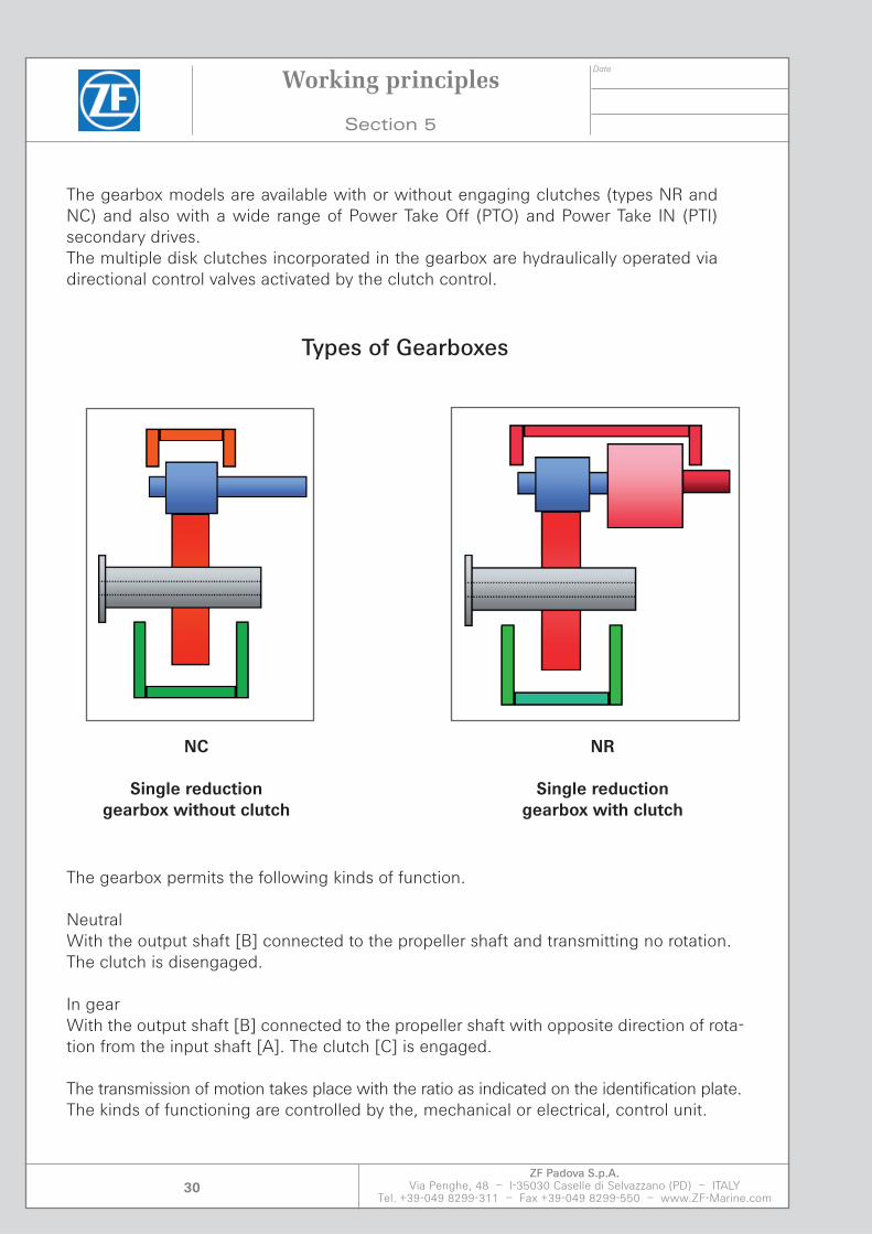
The gearbox models are available with or without engaging clutches (types NR and NC) and also with a wide range of Power Take Off (PTO) and Power Take IN (PTI) secondary drives.The multiple disk clutches incorporated in the gearbox are hydraulically operated via directional control valves activated by the clutch control.
Types of Gearboxes
The gearbox permits the following kinds of function.
NeutralWith the output shaft [B] connected to the propeller shaft and transmitting no rotation.The clutch is disengaged.
In gearWith the output shaft [B] connected to the propeller shaft with opposite direction of rota-tion from the input shaft [A]. The clutch [C] is engaged.
The transmission of motion takes place with the ratio as indicated on the identification plate.The kinds of functioning are controlled by the, mechanical or electrical, control unit.
Working principles
Section 5
NC
Single reductiongearbox without clutch
NR
Single reductiongearbox with clutch
Date
ZF Padova S.p.A.Via Penghe, 48 – I-35030 Caselle di Selvazzano (PD) – ITALY
Tel. +39-049 8299-311 – Fax +39-049 8299-550 – www.ZF-Marine.com31
Working principles
Section 5
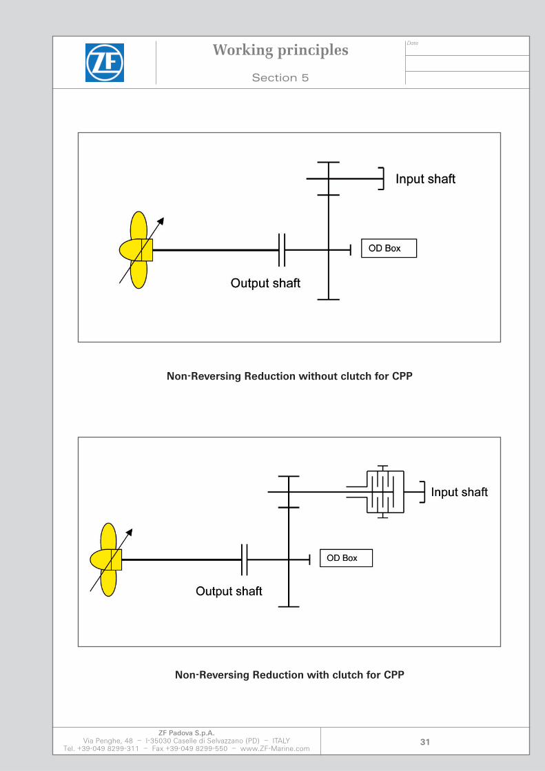
Non-Reversing Reduction without clutch for CPP
Non-Reversing Reduction with clutch for CPP
Date
ZF Padova S.p.A.Via Penghe, 48 – I-35030 Caselle di Selvazzano (PD) – ITALY
Tel. +39-049 8299-311 – Fax +39-049 8299-550 – www.ZF-Marine.com32
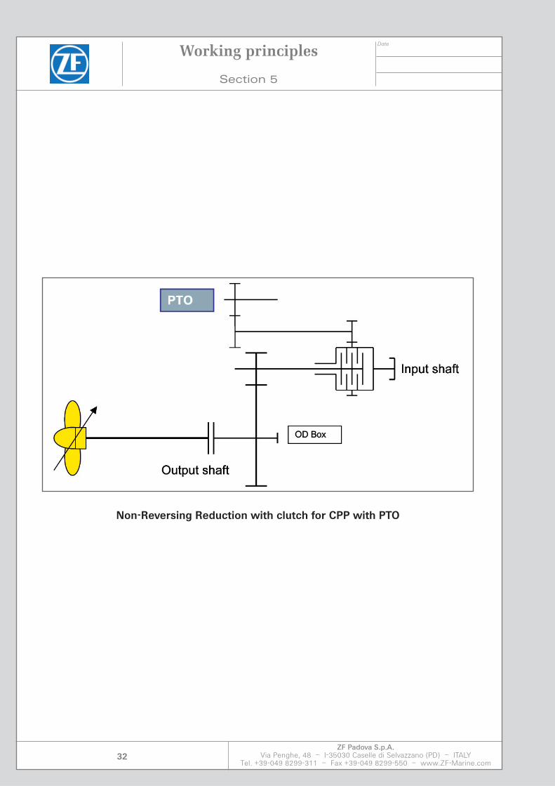
Non-Reversing Reduction with clutch for CPP with PTO
Working principles
Section 5
Date
ZF Padova S.p.A.Via Penghe, 48 – I-35030 Caselle di Selvazzano (PD) – ITALY
Tel. +39-049 8299-311 – Fax +39-049 8299-550 – www.ZF-Marine.com33
Working principles
Section 5
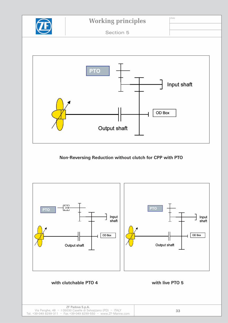
Non-Reversing Reduction without clutch for CPP with PTO
with clutchable PTO 4 with live PTO 5
Date
ZF Padova S.p.A.Via Penghe, 48 – I-35030 Caselle di Selvazzano (PD) – ITALY
Tel. +39-049 8299-311 – Fax +39-049 8299-550 – www.ZF-Marine.com34
Working principles
Section 5
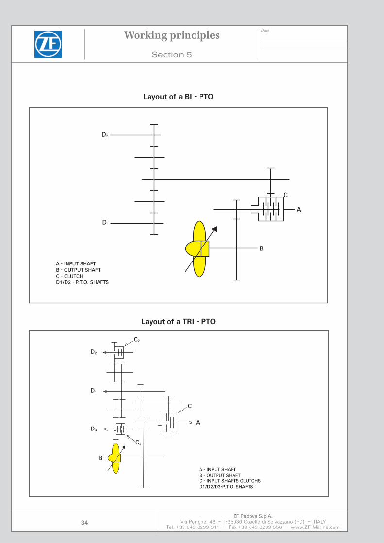
D2
D1
A
B
C
A - INPUT SHAFTB - OUTPUT SHAFTC - CLUTCHD1/D2 - P.T.O. SHAFTS
D1
D2
C2
C3
D3
B
C
A
A - INPUT SHAFTB - OUTPUT SHAFTC - INPUT SHAFTS CLUTCHSD1/D2/D3-P.T.O. SHAFTS
Layout of a BI - PTO
Layout of a TRI - PTO

Date
ZF Padova S.p.A.Via Penghe, 48 – I-35030 Caselle di Selvazzano (PD) – ITALY
Tel. +39-049 8299-311 – Fax +39-049 8299-550 – www.ZF-Marine.com35
Working principles
Section 5
The housing sections are made by rigid cast design or in welded sheet steel construction.Optimum vibration characteristics with excellent smooth running have been additionally achieved by means of pronounced ribbing.The bottom of the housing is used as an oil tanks, this configuration eliminates a very large extent the problems resulting from thermal expansion when aligning the gear box in the ves-sel.On this level of the lower parting line the output shaft with the propeller trust bearing is lo-cated in the rear area. The propeller thrust is transmitted from this bearing via the housing bottom part with its stopper faces directly to the stoppers of the ship foundation.So, no forces caused by the propeller thrust are applied on the remaining housing structure.The housing is exactly fixed to the foundation by closed fitting bolts.The input shaft with the main pinion and the gears, are located on the same level with the output shaft.To ensure service of the gear box there are some covers permitting simple quick inspection of gear system.
Date
ZF Padova S.p.A.Via Penghe, 48 – I-35030 Caselle di Selvazzano (PD) – ITALY
Tel. +39-049 8299-311 – Fax +39-049 8299-550 – www.ZF-Marine.com36
Working principles
Section 5
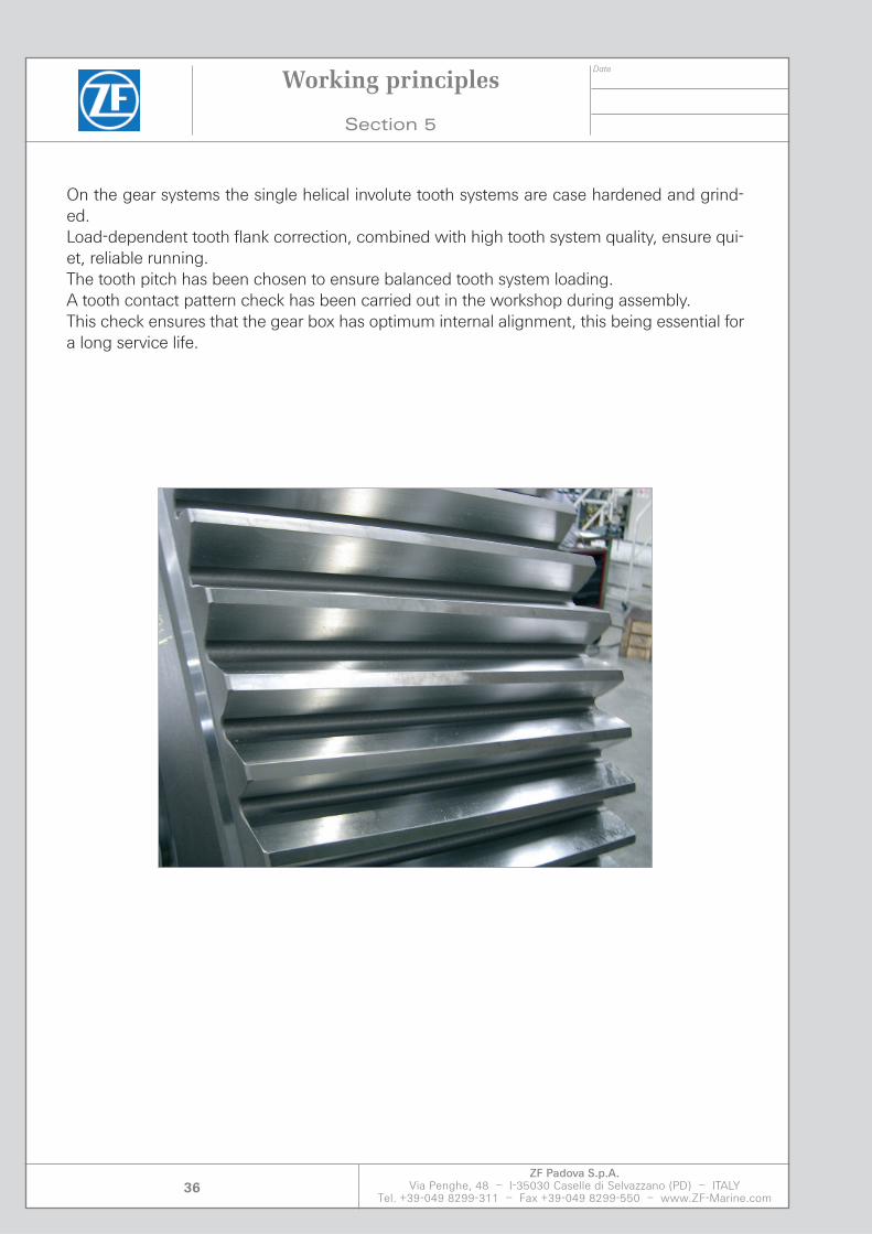
On the gear systems the single helical involute tooth systems are case hardened and grind-ed.Load-dependent tooth flank correction, combined with high tooth system quality, ensure qui-et, reliable running.The tooth pitch has been chosen to ensure balanced tooth system loading.A tooth contact pattern check has been carried out in the workshop during assembly.This check ensures that the gear box has optimum internal alignment, this being essential for a long service life.
Date
ZF Padova S.p.A.Via Penghe, 48 – I-35030 Caselle di Selvazzano (PD) – ITALY
Tel. +39-049 8299-311 – Fax +39-049 8299-550 – www.ZF-Marine.com37
Working principles
Section 5
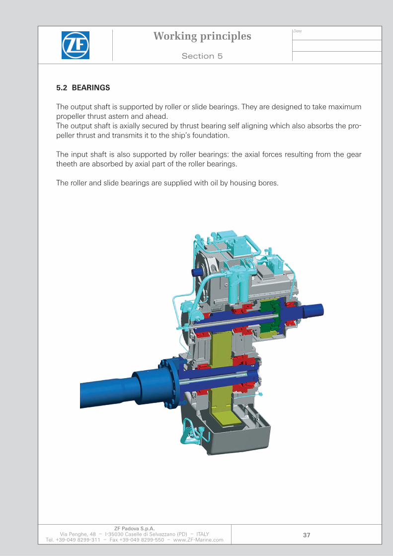
5.2 BEARINGS
The output shaft is supported by roller or slide bearings. They are designed to take maximum propeller thrust astern and ahead.The output shaft is axially secured by thrust bearing self aligning which also absorbs the pro-peller thrust and transmits it to the ship’s foundation.
The input shaft is also supported by roller bearings: the axial forces resulting from the gear theeth are absorbed by axial part of the roller bearings.
The roller and slide bearings are supplied with oil by housing bores.

Date
ZF Padova S.p.A.Via Penghe, 48 – I-35030 Caselle di Selvazzano (PD) – ITALY
Tel. +39-049 8299-311 – Fax +39-049 8299-550 – www.ZF-Marine.com38
Working principles
Section 5
The gear system is oiling with an oil pump, that is use for engagement of the clutch.
The oil pump receives the motion of the shaft entrance and the speed of rotation depends on the revolutions of the engine.
The oil pressure is maintained constant by means of the distributor.
The oil is cooled by an heat exchanger made by cooling tubes which are resistant to salty sea water.The volume of heat generated in the gearbox is removed partly by radiating from the surface of the housing and partly through the oil cooler the oil cooler included in the basic version of the gearbox is mounted on the housing.All the necessary oil lines are securely attached and ready for operation.For permissible water flow rate and pressure loss between cooling water inlet and outlet the speci-fied water pressure and temperature at the cooling water inlet must not be exceeded.The correct gearbox temperature is achieved by adjustment of the cooling water flow rate.A replaceable orifice, valve or similar device must be included in the ciruit for this purpose.For this reason, the gearbox water circuit should be arranged in a by-pass from the engine cooling water circuit. The maximum temperature increase of the cooling water in the gearbox oil cooler is 3 °C and is of no significance to the engine oil circuit.The stated maximum cooling water flow through the gearbox oil cooler must not be exceeded since this may lead to cavitation in the cooler.Similarly, the minimum flow rate must always be maintained or else sludge may form in the cooler after only a relatively short period of operation.
Before being cooled, the oil passes through a double oil filter with a contamination indicator.
Simplified hydraulics diagram
Fig. 2.1
Date
ZF Padova S.p.A.Via Penghe, 48 – I-35030 Caselle di Selvazzano (PD) – ITALY
Tel. +39-049 8299-311 – Fax +39-049 8299-550 – www.ZF-Marine.com39
Working principles
Section 5
Seals
The split - type seals, because of the labyrinth inside prevent any leakage of lube oil at the input and output shafts.
They are designed for an easy maintenance.
Clutch
The multiple disk clutches incorporated in the gearbox are hydraulically operated via direc-tional control valves activated by the clutch control.
A smooth and reliable hydraulic shifting electrically activated is obtained by a pressure modulation.
Stand-by oil pump
The electrical driven stand-by pump supplies the gear box with oil prior to startup. If neces-sary, this pump will also perform the function of the oil pump fitted to the gear box.
During the installation of the stand by pump verify that the suction pressure is not lower than - 0,6 bar.

Date
ZF Padova S.p.A.Via Penghe, 48 – I-35030 Caselle di Selvazzano (PD) – ITALY
Tel. +39-049 8299-311 – Fax +39-049 8299-550 – www.ZF-Marine.com40
5.3 MONITORING
The marine gearbox has been designed for the connection of the instruments (monitoring) in order to record the oil pressure, temperature and level according with the Classification Society requirements.
Working principles
Section 5

Section 6

Date
ZF Padova S.p.A.Via Penghe, 48 – I-35030 Caselle di Selvazzano (PD) – ITALY
Tel. +39-049 8299-311 – Fax +39-049 8299-550 – www.ZF-Marine.com43
Installation Description
Section 6
Installation Description
6.1 INTRODUCTION
This section describes the installation of the gearbox and appropriate products. The drawings to which the descriptions refer are included in the Appendix. The preceding safety notes must be carefully observed.
• Put the gearbox on the foundation top plate and, before removing the hoisting elements, secure it in this position to prevent dislocation.
• Make sure the gearbox is set down on the alignment bolts only.
• Make sure the gearbox housing is not subjected to distortion and properly connected to the ship’s foundation.
• Make sure the pipes for the lubrication and cooling system are connected to the gearbox in a flexible manner.
The pipes and fittings for supplying the seawater cooler and for the auxiliary pump are to be supplied by the shipyard.
The connection must be free from stress caused by vibration.
• Make sure pipes and connections are cleaned before installation; they must be free from scales and welding beads.
• Absolutely avoid heavy blows and shocks.
• Make sure the gearbox housing, input and output shafts are not subjected to high axial forces.
Date
ZF Padova S.p.A.Via Penghe, 48 – I-35030 Caselle di Selvazzano (PD) – ITALY
Tel. +39-049 8299-311 – Fax +39-049 8299-550 – www.ZF-Marine.com44
Installation Description
Section 6
• Protect the gearbox against damage, humidity and dirt.
• Remove blank flanges and plugs closing off oil and cooling water connections only after gearbox mounting has been completed.
• Change the setting of the pressure control valves and monitoring devices only in cooperation with ZF
Note: Modifications on the setting of the (Clutch Control Unit) are only allowed by authorized ZF personnel.
• Only use the accessories supplied by ZF. The risks associated with the use of third-party products lies solely with the client.
Date
ZF Padova S.p.A.Via Penghe, 48 – I-35030 Caselle di Selvazzano (PD) – ITALY
Tel. +39-049 8299-311 – Fax +39-049 8299-550 – www.ZF-Marine.com45
Installation Description
Section 6
6.2 MOUNTING WORK TO BE PERFORMED
6.2.1 Gearbox
Clean gearbox supporting surfaces, input shaft output flange and pipe connections faces to remove the anti-corrosive agents.
Make sure there are no oil or grease on the cleaned surfaces.
Align the gearbox properly in relation to the propeller line shafting calculation.
Make a prealignment in dry dock.
Expertly mount the gearbox and tighten the holding down bolts as instructed.
Connect the flange of the gearbox output shaft to the flange of the propeller line shafting using close fitting bolts.
Remove any blank flanges and plugs closing off openings where piping connects.
Make sure that the transmission has been installed while leaving the space necessary for future maintenance. The transmission must be anchored to the foundation of the gearbox with adequate fastenings in order to prevent any compensations to the housing of the transmission.
6.2.2 Electric motor for stand by pump
• Take care that there is no restriction of the cooling air passage to and away from the electric motors.
• Take suitable measures to prevent the hot waste air from being in again.
The electrical connection of the electric motors is to be done as outlined below. Be sure to observe respective safety notes. Disconnect (de-energize) the equipment from the power supply.
Make sure all mounting and installation work is only performed when the equipment has been disconnected from the electrical supply system.
Date
ZF Padova S.p.A.Via Penghe, 48 – I-35030 Caselle di Selvazzano (PD) – ITALY
Tel. +39-049 8299-311 – Fax +39-049 8299-550 – www.ZF-Marine.com46
Installation Description
Section 6
• Make sure that only skilled expert personnel is entrusted with the required work and that these persons undertake to strictly adhere to the applicable rules and supplied documentation.
Before making the respective connections check the data given on the rating plate.
Take care that these data coincide with the conditions prevailing aboard (voltage and frequency).
• Make sure that the size of the connecting cables suits the nominal current of the electric motors.
• Make sure that the electric pump start and stop functions are connected according to the Classification Society.
• Be sure that cabling connections are made as instructed on the circuit diagram provided in the terminal box of the electric motors.
Note: The type of connection depends on the starting method used, i.e. “direct-on-line” or “star-delta”, and will be prescribed by the shipyard.
• Note that connection of electric motors must suit the prescribed rotational direction.
• Take care that the protective conductor is connected with the appropriately marked terminal.
• Make sure that the rotational directions indicated by arrows on electric motors and oil pumps coincide as required.
Attach the connecting cables to the terminal plate of the electric motors.
During the installation of the stand by pump verify that the suction pressure is not lower than – 0,6 bar.In case the stand-by pump is not already fitted on the gearbox a flexible fire-proof connection is recommended between the pump and the piping. Working pressure: 30 bar.If the connection will be rigid, respect the concentricity between the flanges in order to avoid residual stress on the piping.

Date
ZF Padova S.p.A.Via Penghe, 48 – I-35030 Caselle di Selvazzano (PD) – ITALY
Tel. +39-049 8299-311 – Fax +39-049 8299-550 – www.ZF-Marine.com47
Installation Description
Section 6
6.2.3 Oil cooler
Attach the cooling water pipes to the inlet and outlet nozzles provided on the front end of the oil cooler.
Note: Make sure that only pipework and elbows are used that have the nominal diameters specified by ZF, refer to respective drawings in the Appendix.
• Attention need be paid to the direction of flow when connecting the water carrying piping.
6.2.4 Monitoring system
The electrical installation shall be effected as outlined below. The preceding safety notes must be carefully followed.
Make sure all mounting and installation work is only performed after the equipment has been disconnected from the electrical supply system.
• Make sure that only skilled expert personnel is entrusted with the necessary work. These persons must undertake to strictly adhere to the applicable rules and supplied documentation.
• Make sure cabling is laid in suitable cable raceways or trays so that they are effectively protected.
Connect the cables leading on to the engine control room via the terminal block arranged in the switch cabinet following the enclosed wiring diagram (see appendix).
Note: Make sure that the size of the connecting cables suits the requirements. • Make sure that the monitoring is connected according to the classification society.

Date
ZF Padova S.p.A.Via Penghe, 48 – I-35030 Caselle di Selvazzano (PD) – ITALY
Tel. +39-049 8299-311 – Fax +39-049 8299-550 – www.ZF-Marine.com48
6.3. ALIGNMENT WORK TO BE PERFORMED
Measures to be taken for gearbox alignment are described below.
Note: The alignment must be verified while the craft is in the water.Make sure that the hull does not come in contact with the sea floor.
Before launch secure the transmission against movement.
Secure the shaft propeller against turning.
• Be sure to mount the gearbox with associated coupling removed so that the gearbox housing is free from distortions when being attached to the ship’s foundation.
• Prerequisite for a trouble-free operation of the gearbox is that the output and input ends are carefully aligned.
Displacement that may arise during operation must be duly taken into account when aligning the unit. Such displacements result from a thermal expansion of the gearbox housing and operating position of the output and input shafts.
Note: As required by the respective alignment temperatures and the shaft’s rotational direction observe the necessary compensation values and their measuring points as per the Diagram Reported in the appendix (see Appendix).
Generic behaviour of thermal growth
This diagram show the characteristic compensation curve caused by the operational temperature on the input output shaft of the transmission and permits an high precision in cold alignment.
Installation Description
Section 6
Operating Temperature

Date
ZF Padova S.p.A.Via Penghe, 48 – I-35030 Caselle di Selvazzano (PD) – ITALY
Tel. +39-049 8299-311 – Fax +39-049 8299-550 – www.ZF-Marine.com49
Installation Description
Section 6
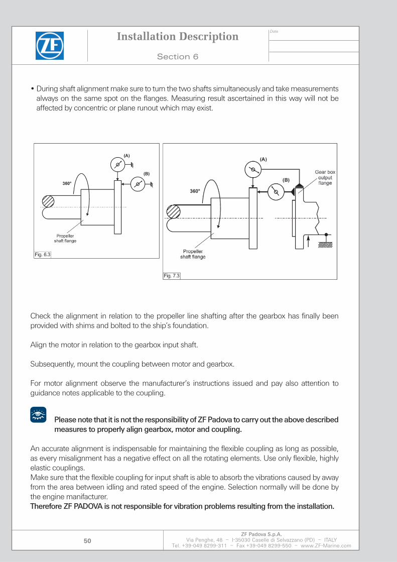
6.3.1 Radial and axial run-out
A prerequisite for the correct alignment of the gear box with respect to the propeller shaft is to avoid allowing the shaft to lower or bend due to the weight of the shaft itself and the propeller shaft flange.
Align the gearbox standing on the alignment bolts in relation to the propeller line shafting. For horizontal alignment suitable set screws must be arranged laterally on the four corners of the gearbox baseplate.
Note: The location of the alignment bolts can be seen from the installation drawing included in the Appendix.
Note: For alignment purposes check the elastic line calculations established for the propeller line shafting and take from it the respective values regarding deflection and gap between the two shafts.
Also you have to check the radial and axial run-out of the propeller shaft flange.For this verification, the output flange of the transmission must not be in contact to the propeller shaft.
Take care to not damage the shaft seal with uncareful movement.
Position a comparator (A) so that the feeler is radially in contact with the propeller shaft flange and a second comparator (B) must be positioned perpendicular to the face of the flange, as shown in the illustration. (Fig. 6.3) The comparator (A) detects the radial run-out and the comparator (B) detects the axial run-out.
6.3.2 Radial and angular misalignment
For this check go ahead like shown in (fig. 7.3)Put the comparator (A) and (B) like discribed and fix them to the output flange of the gearbox.The comparator (A) detects the absolute radial error and (B) the angular error referenced to a flange with diameter of 500 mm.
At operation temperature and under full load the allowable deviations are:Radial and axial run-out max: 0.04 mmRadial and angular misalignment max: 0.05 mm (on 500 mm)
• To avoid measuring errors when determining the amount of angular displacement during alignment turn the gearbox shafts in one direction only. Changing the direction of rotation will cause shaft displacement in the gearbox housing due to roller bearing play.
Date
ZF Padova S.p.A.Via Penghe, 48 – I-35030 Caselle di Selvazzano (PD) – ITALY
Tel. +39-049 8299-311 – Fax +39-049 8299-550 – www.ZF-Marine.com50
• During shaft alignment make sure to turn the two shafts simultaneously and take measurements always on the same spot on the flanges. Measuring result ascertained in this way will not be affected by concentric or plane runout which may exist.
Check the alignment in relation to the propeller line shafting after the gearbox has finally been provided with shims and bolted to the ship’s foundation.
Align the motor in relation to the gearbox input shaft.
Subsequently, mount the coupling between motor and gearbox.
For motor alignment observe the manufacturer’s instructions issued and pay also attention to guidance notes applicable to the coupling.
Please note that it is not the responsibility of ZF Padova to carry out the above described measures to properly align gearbox, motor and coupling.
An accurate alignment is indispensable for maintaining the flexible coupling as long as possible, as every misalignment has a negative effect on all the rotating elements. Use only flexible, highly elastic couplings.Make sure that the flexible coupling for input shaft is able to absorb the vibrations caused by away from the area between idling and rated speed of the engine. Selection normally will be done by the engine manifacturer.Therefore ZF PADOVA is not responsible for vibration problems resulting from the installation.
Installation Description
Section 6

Date
ZF Padova S.p.A.Via Penghe, 48 – I-35030 Caselle di Selvazzano (PD) – ITALY
Tel. +39-049 8299-311 – Fax +39-049 8299-550 – www.ZF-Marine.com51
6.4 FASTENING WORK TO BE PERFORMED
Bedding of the gearbox on cast-iron/steel adapters or resinoid adapters and subsequent fastening to the ship’s foundation are effected as described below.Stoppers or fitted bolts must transfer the propeller thrust in the gear foundation.
Gearbox foundation
Note: Make sure that the bores for the foundation bolts have been provided in the ship’s foundation in line with the shipyard’s job scheduling.
• The arrangement of the bores in the gearbox foundation plate is shown in the installation drawing included in the Appendix.
Before foundation work is carried out the respective drawings and calculation data must have been prepared by the Contractor performing the work and submitted to the classification society for approval.
Note: Please note that all foundation work is subject to the respective rules and regulations issued by the classification society.
Installation Description
Section 6

Date
ZF Padova S.p.A.Via Penghe, 48 – I-35030 Caselle di Selvazzano (PD) – ITALY
Tel. +39-049 8299-311 – Fax +39-049 8299-550 – www.ZF-Marine.com52
• Make sure that all loads affecting the sizing of the required shims are duly taken into account: torque, propeller thrust and deadweight of the gearbox.
The supports must be adequately sized and tightly anchored to the gearbox foundation.You can use either the foundation screws with the supports or the transmission screws.Only rectangular set chock type support are permitted and the material must be agreed with the “Certifying Authorities”. The support surface of the ZF mounting bracket has been designed for direct mounting on a rigid surface.
Once the casting resin has hardened, the gearbox should only be supported by the casting resin and not by the alignment screws or any other alignment aids. When aligning the gearbox, the way in which the casting resin reacted to shrink fitting during hardening should be taken into consideration.
We recommend that plans for the design of any mountings made of casting resin are made in conjunction with the casting resin supplier and/or a certified specialist company. A specialist company is able to provide advice at an early stage and is able to create the calculations and drawings required for approval from a classification society and to submti these for approval.The anchoring screws must be at least class 8.8 ISO 898 steel and they must comply with requirements in consideration of the vessel specifications. Tightening torque values depend on the vessel specifications. Make sure the transmission does not shift longitudinally due to the effect of the axial thrust exerted by the propeller.Use longitudinal foundation shirms in steel. Make a final check of alignment and, if satisfactory, secure the screws with double nuts. Mark the nut threads with paint to facilitate periodic bolt tightness visual inspections.
Installation Description
Section 6

Section 7


Date
ZF Padova S.p.A.Via Penghe, 48 – I-35030 Caselle di Selvazzano (PD) – ITALY
Tel. +39-049 8299-311 – Fax +39-049 8299-550 – www.ZF-Marine.com55
Starting Operation
Section 7
Starting Operation
7.1 INTRODUCTION
This section describes the preparatory measures and course of action to be followed when taking the gearbox into and out of service. The respective notes on safety shall be duly observed.The safety and maintenance are prerequisites for trouble-free operation, maximum performance and along service life.
Do not touch any rotating parts.
Periodic supervision and registration of measured parameters provides a duty profile for the marine gearbox.
Provide for the arrangement of adequate touch guards for all rotating parts located on the input and output side of the gearbox.
Check the correct operating position of the stop valves and gate valves mounted in the piping system.
Note: Make sure the stop valves arranged in the oil discharge lines between gearbox and contami-nated oil tank are closed.
When carrying out the following activities make sure that no lubricants are discharged into the environment.
Date
ZF Padova S.p.A.Via Penghe, 48 – I-35030 Caselle di Selvazzano (PD) – ITALY
Tel. +39-049 8299-311 – Fax +39-049 8299-550 – www.ZF-Marine.com56
7.2 PREPARATORY MEASURES
Note: Please note that ZF has adjusted the pressure relief valves of the motor-driven oil pump units to the prescribed pressures as well as the switching points of the monitoring devices.
Fill clean oil into the gearbox system as prescribed by the lubricating oil specification and follow the procedures and instruction given below:
When filling the system take care that no dirt, foreign matter or water are allowed to enter the gearbox interior.
Note: A list of approved oil brands forms is reported in the Appendix.
• Note down the volume of oil filled in when carrying out oil changes within the scope of mainte-nance work.
• Other oil brands must only be used if ZF approval has been obtained. The risk of damage in case a non-approved product is product is employed lies solely with the Owner.
Before first start be sure that the cartridges are present in the twin-type filter.
Fill the operating oil volume into the gearbox, when gear unit stands still: the correct oil level is between the two marks on the oil dipstick.
Check and, if necessary, correct the oil level, when stand-by pump is switch on.Using the transmission with an insufficient quantity of oil air may be taken in by the pump.
On the other hand, on high quantity of oil could result in leakage through the gaskets and vents, and could cause the operational temperature to increase significantly, including low clutch pres-sure.
Top both oil pump up with oil through the connection located upstream of each of the intake noz-zles to avoid the pumps running dry when first taken into service.
Starting Operation
Section 7

Date
ZF Padova S.p.A.Via Penghe, 48 – I-35030 Caselle di Selvazzano (PD) – ITALY
Tel. +39-049 8299-311 – Fax +39-049 8299-550 – www.ZF-Marine.com57
Check if the non return valves are assembled correctly.
• Gearbox and dil pipes have to be flushed using the stand-by pump for at least two hours.
• Inspect the filter and eventually clean it.
Make up the cooling water supply connection to the oil cooler and make sure that the cooling water pressure is lower than the oil pressure. This will largely safeguard the in the lubricating oil circuit against the ingress of water in the event of a cooler leakage.
Note: Be sure that the rated current level indicated on the electric motor rating plate is not exceeded.
Check the fittings for possible oil learage.Check the oil supply and monitoring system for leakage and proper functioning.Check the negative pressure at the intake connection of the oil pump.
Note: Take care that the determined negative pressure does not exceed 0,6 bar.
Check the oil pressure on the discharge connection of the oil pump via the attached pressure gauge.
Take care that the determined negative oil pressure does not exceed 0,6 bar.
Should oil pressure corrections be necessary they are effected via the pressure relief valve at-tached to the oil pump.
Check and, if necessary, correct the oil level once more. Observe the markings on the oil dipstick.Check all rotating parts for ease of movement by rotating the propulsion system.
Starting Operation
Section 7
Date
ZF Padova S.p.A.Via Penghe, 48 – I-35030 Caselle di Selvazzano (PD) – ITALY
Tel. +39-049 8299-311 – Fax +39-049 8299-550 – www.ZF-Marine.com58
7.3 COMMISSIONING ACTIVITIES
Initial commissioningSwitch on motorized oil pump unit. The motorized oil pump unit- prelubricates the gearbox.Start the propulsion system and slowly increase the speed to approx. 50% of rated speed. Operate the gearbox under partial load at abt. 25% of rated torque until the oil temperature at the gearbox input is approx. 45°C at an oil pressure of 2 ± 0.5 bar. Gradually increase the load to 40% of rated torque and maintain this load for a period of approx. 3 hours.
Slowly increase speed and power. Maintain a load corresponding to 70% of rated torque for a period of abt. 3 hours before operating the system under full load.
Check the contact patterns of the tooth flanks of all pinions and gears after approx. 10 hours full-load operation.
For correction clutch functioning, the gear engaging must take place in a reasonably short time.The maximum speed allowed for the gear engaging should be about 60% of the maximum en-gine rotation.
Reduce speed and power if the bearing temperatures are found to be inadmissibly high.
Bearing temperature, lubricating oil pressure limits and the oil supply are specified in the technical data.
To be able to detect any malfunctions in good time and thus to implement preventive measures, monitoring during operation is indispensable.It is advisable to note the operating pressures, oil temperature and bearing temperatures regularly.
If irregularities are detected during operation (noise, vibration) or if the operating data change, the system should be shut off immediately and the cause established.
Therefore, check after approx.. 10 hours full-load operation:- all bolted connections and pipe couplings / union for tightness as well as - the complete gearbox installation for leakage.
Tighten all loose bolted connections and pipe couplings at the prescribed torque rate.
Starting Operation
Section 7
Date
ZF Padova S.p.A.Via Penghe, 48 – I-35030 Caselle di Selvazzano (PD) – ITALY
Tel. +39-049 8299-311 – Fax +39-049 8299-550 – www.ZF-Marine.com59
• Replace damage gaskets/seals when the unit is stationary and the engine is in cold state.
Observe the noise and vibration characteristics of the gearbox system during all operating states.
Note: In the event of irregularities please notify the service department of ZF immediately.
Check the operating chamber of the twin-type filter for fouling.
Note: The contact-type differential pressure gauge attached to the twin-type filter indicates even minor states of filter fouling.
Check the settings of the pressure monitoring equipment.
Note: The nominal switch points are listed in the oil supply and monitoring diagram included in the Appendix.
Check the oil level of the gearbox. If the oil level is found to be incorrect the oil volume must be topped up as required.
When initial commissioning has been completed prepare the respective protocol and submit one copy of it to ZF service department.
Note: This document will be added to the production data compiled by ZF and shall serve as a basis in the event warranty claims are raised.
7.3.1 Towing
During if the navigation in tow, it will be necessary to lubricate the rotating parts for at least five minutes.Lubrication can be done by the stand by pump.If lubrication is not possible, the propeller shaft must be blocked in order to prevent its rotation as a result of the dragging effect, otherwise you can damage the gearbox.Continuous trailing operation is possible with a stand by pump running.
Starting Operation
Section 7

Date
ZF Padova S.p.A.Via Penghe, 48 – I-35030 Caselle di Selvazzano (PD) – ITALY
Tel. +39-049 8299-311 – Fax +39-049 8299-550 – www.ZF-Marine.com60
7.4 SHUTDOWN ACTIVITIES
When the transmission system is shut down for a maximum period of one week no special meas-ures need be taken. If the shutdown period exceeds one week the propulsion system must be turned once a week to prevent corrosion and oil gumming.
Note: Make sure the turning operation takes place when the motorized oil pump unit is switched on.
After stop gearbox turning the stand by pumps has to work at leat 10 min. in order to gradually cool the transmission.
• Switch off the respective motor-driven oil pump when turning has been completed.
Stop the cooling water flow to the oil cooler and drain the cooler via the respective drain plugs provided.
Check the gearbox system for damage, leakage, corrosion and untight components.
Water in the lubricating oil is especially dangerous. A bearing can run for a short time with a limited quantity of water in the oil, but thus may NEVER be allowed to happen with a gear wheel as wate, even in the smallest quantities, causes immediate pitting. To prevent condensed moisture forming in the casing during operation and above all during stationary periods the gear unit is vented. The air heats up in the gear unit and is thus able to absorb the moisture. After the system has been shut off, ensure that no engine room fans are directed at the casing. This applies particularly in tropical zones, where considerable temperature gradients must be expected, especially at night.
Starting Operation
Section 7
Date
ZF Padova S.p.A.Via Penghe, 48 – I-35030 Caselle di Selvazzano (PD) – ITALY
Tel. +39-049 8299-311 – Fax +39-049 8299-550 – www.ZF-Marine.com61
ZF Reduction Gearbox Commissioning Checklist
Gearbox Serial No.: .......................................................................
Shipyard: .......................................................................
New Building No.: .......................................................................
Commissioning Engineer(s): 1) ...................................................................
2) ...................................................................
3) ...................................................................
ZF Commissioning Report
Section 7

Date
ZF Padova S.p.A.Via Penghe, 48 – I-35030 Caselle di Selvazzano (PD) – ITALY
Tel. +39-049 8299-311 – Fax +39-049 8299-550 – www.ZF-Marine.com62
1.0 VISUAL INSPECTION
1.1 Are there any visible damages? � OK1.2 Check external condition of gearbox � OK
1.3 Are there any parts missing or exchanged by non Genuine Spare parts? � OK
2.0 INSTALLATION
2.1 Thermal Alignment Engine Gearbox after Chockfast Recomendation:
Mesured:Temperature in Engine Room ______________ [°C]
2.2 Thermal Alignment Gearbox-Shaft Alternator after Chockfast Recomendation:
Mesured:Temperature in Engine Room ______________ [°C]
2.3 INSTALLATION OF THE GEARBOX (yard)
Front StopperSide StopperFitted boltsTightening Torque: ___________________[Nm]
� O.K.� O.K.� O.K.� O.K.
2.4 INSTALLATION OF THE engine (yard)
ChockfastResilient
� O.K.� O.K.
ZF Commissioning Report
Section 7

Date
ZF Padova S.p.A.Via Penghe, 48 – I-35030 Caselle di Selvazzano (PD) – ITALY
Tel. +39-049 8299-311 – Fax +39-049 8299-550 – www.ZF-Marine.com63
3.0 COOLING WATER SYSTEM
3.1 Heat exchanger attached to the gearbox � OK3.2 Cooling water pipes connected with compensators � OK
4.0 LUBRIFICATION SYSTEM
4.1 Standby PumpAre the pipes of the stand-by pump connected by compensators? � OK (yard)
4.2 Height from suction flange bottom of gearbox to pump suction flange: _________________ [cm]
4.3 Oil Filing
Lube oil manufacturer:Type / S.A.E.:Filing litres:
_________________________________________ (yard)_________________________________________ (yard)_________________________________________ (yard)
4.4 Where the pipes acidified and cleaned?
Was the lub oil system flusched with stan-dby pump at least hour?
� OK
� OK
4.5 Operation with standby pump
Clutch oil pressure: __________________________________________ [bars]
Lub oil pressure: __________________________________________ [bars]
Leakage? � OK 5.0 RUN AT SEA TRIALS
5.1 At Endurance Test (Measure min. 3 hours after continuos operation)
Oil Temperature:Thrust Bearing Temperature:Clutch oil pressure:Lube oil pressure:
__________________________________________ [°C]__________________________________________ [°C]________________________________________ [bars]________________________________________ [bars]
5.2 Oil leakage? � OK
5.3 After turning off the engine open inspection cover internal condition of the gearbox:
Good: �Corroded: �Defects: �
ZF Commissioning Report
Section 7
Date
ZF Padova S.p.A.Via Penghe, 48 – I-35030 Caselle di Selvazzano (PD) – ITALY
Tel. +39-049 8299-311 – Fax +39-049 8299-550 – www.ZF-Marine.com64
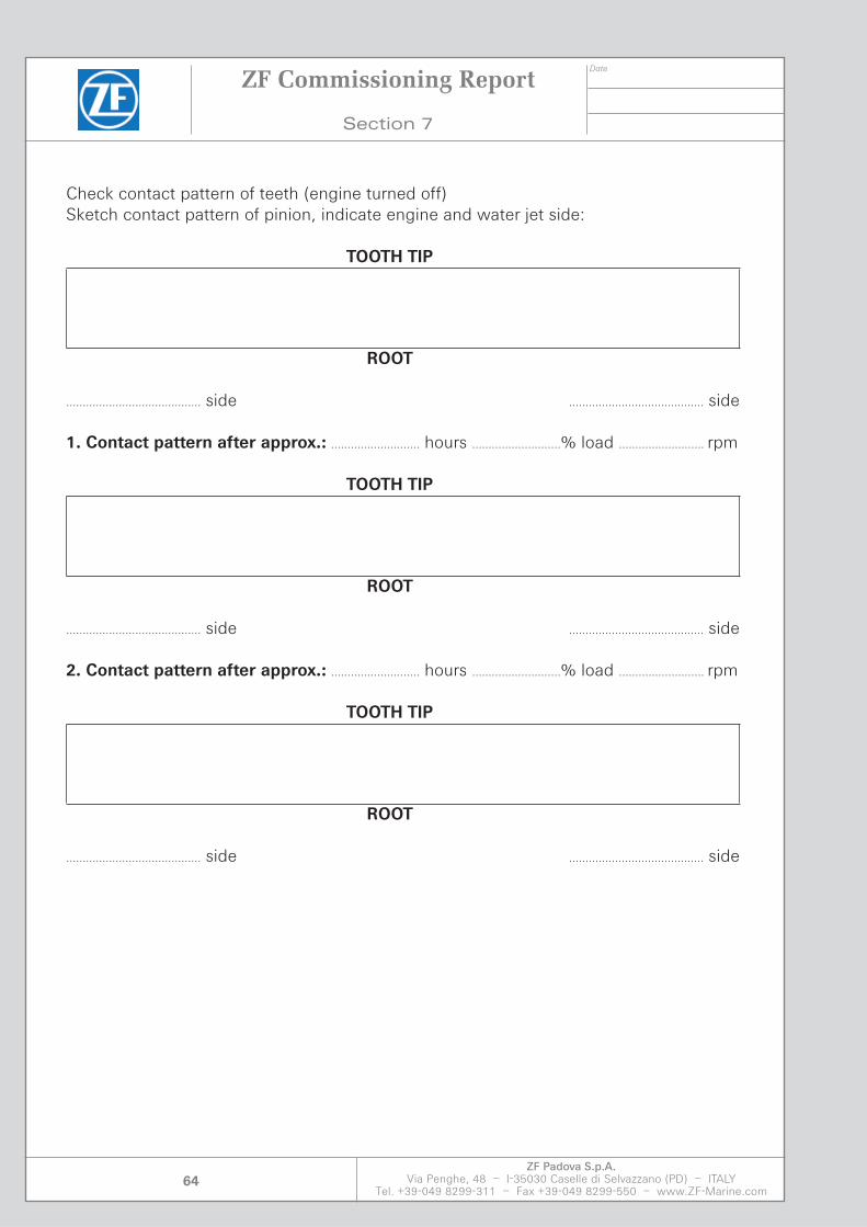
Check contact pattern of teeth (engine turned off)Sketch contact pattern of pinion, indicate engine and water jet side:
TOOTH TIP
ROOT
......................................... side ......................................... side
1. Contact pattern after approx.: ........................... hours ...........................% load .......................... rpm
TOOTH TIP
ROOT
......................................... side ......................................... side
2. Contact pattern after approx.: ........................... hours ...........................% load .......................... rpm
TOOTH TIP
ROOT
......................................... side ......................................... side
ZF Commissioning Report
Section 7
Date
ZF Padova S.p.A.Via Penghe, 48 – I-35030 Caselle di Selvazzano (PD) – ITALY
Tel. +39-049 8299-311 – Fax +39-049 8299-550 – www.ZF-Marine.com65
COMMENTS:
..............................................................................................................................................................................................
..............................................................................................................................................................................................
..............................................................................................................................................................................................
..............................................................................................................................................................................................
..............................................................................................................................................................................................
..............................................................................................................................................................................................
..............................................................................................................................................................................................
Acceptance Statement
For Shipyard: Name Surname: ..................................................................................................
Position: ..................................................................................................
Signature: ..................................................................................................
Date: ..................................................................................................
For Avk: Name Surname: ..................................................................................................
Position: ..................................................................................................
Signature: ..................................................................................................
Date: ..................................................................................................
ZF Commissioning Report
Section 7

Date
ZF Padova S.p.A.Via Penghe, 48 – I-35030 Caselle di Selvazzano (PD) – ITALY
Tel. +39-049 8299-311 – Fax +39-049 8299-550 – www.ZF-Marine.com66
Remarks
..............................................................................................................................................................................................
..............................................................................................................................................................................................
..............................................................................................................................................................................................
..............................................................................................................................................................................................
..............................................................................................................................................................................................
..............................................................................................................................................................................................
..............................................................................................................................................................................................
ZF Commissioning Report
Section 7

Section 8

Date
ZF Padova S.p.A.Via Penghe, 48 – I-35030 Caselle di Selvazzano (PD) – ITALY
Tel. +39-049 8299-311 – Fax +39-049 8299-550 – www.ZF-Marine.com69
Emergency Operation
Section 8
Emergency Operation
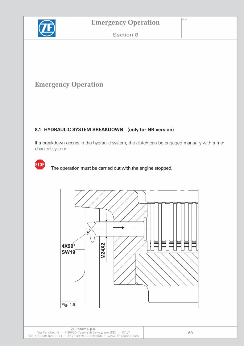
8.1 HYDRAULIC SYSTEM BREAKDOWN (only for NR version)
If a breakdown occurs in the hydraulic system, the clutch can be engaged manually with a me-chanical system.
The operation must be carried out with the engine stopped.

Date
ZF Padova S.p.A.Via Penghe, 48 – I-35030 Caselle di Selvazzano (PD) – ITALY
Tel. +39-049 8299-311 – Fax +39-049 8299-550 – www.ZF-Marine.com70
8.2 EMERGENCY OPERATION
Stop the engine and ensure that it is not involuntarily started up (set the control unit to neutral). Remove the relative inspection cover. Tighten screws SW19 (tightening torque 71 Nm) evenly in a diametrically opposite sequence in two steps. The disk pack is compressed and the clutch is engaged. Set the control unit to NEUTRAL. The propeller shaft will turn as soon as the engine is started.
Note: The utmost caution must be exercised during emergency operation with the main clutch. When emergency screws SW19 are tightened, maximum torque transmission is permitted. Once the problem has been solved, loosen the screws completely. On arrival in port check the clutch disks and unscrew the bolts SW19 up to the original position. If the transmission is used repeatedly in emergency mode strip it down and check all bearings and gearing components carefully.
Make sure the engine and propeller are at a stand still before carrying out kind of operation on the gear box.
Emergency Operation
Section 8

Date
ZF Padova S.p.A.Via Penghe, 48 – I-35030 Caselle di Selvazzano (PD) – ITALY
Tel. +39-049 8299-311 – Fax +39-049 8299-550 – www.ZF-Marine.com71
8.3 MECHANICAL ACTIVATION GUIDE
101 Electrical control unit102 Neutral position105 Gear lever for emergency mechanical operation106 Plug/socket connection
In the event of an electrical actuator fault, the gearbox can be operated mechanically by means of the emergency lever. For safety reasons the normal actuator device should be disabled before us-ing the emergency lever. This is achieved by unplugging the electrical connector from its socket.The electrical actuator connected to the control unit is designed in such a way that the selected position is maintained in the event of an electrical power loss. The emergency lever can be moved manually. During the movement the operator will be able to note the detented operating posi-tions.
DANGER - If the electrical supply is cut off, the running position will be maintained.
The emergency lever will remain in the selected position.Consult your nearest ZF Service Centre for the necessary repairs.
Emergency Operation
Section 8

Date
ZF Padova S.p.A.Via Penghe, 48 – I-35030 Caselle di Selvazzano (PD) – ITALY
Tel. +39-049 8299-311 – Fax +39-049 8299-550 – www.ZF-Marine.com72
8.4 NOTES ON OPERATION UNDER SPECIAL CONDITIONS
Action required at low shaft speed
It must be ensured that the standby engine oil pump unit is switched on under the following op-erating conditions:
- Turning of the gearbox for inspection purposes by means of the turning engine
- Driven propeller by approach flow with Diesel engine uncoupled.
Dragging of the propeller shaft
It has to be taken into account that, with the clutch shut down and the motors running, a torque is being transmitted onto the propeller shaft due to residual friction between the clutch disks. Under special conditions it is, therefore, possible that the propeller shaft is driven. The probability of the propeller shaft being dragged is aided by the following circumstances:
- The disks of the clutch are new.
- Cold lube oil in circulation.
- Two or more drives are acting on the same output.
- In the case of a short overall length of the output shaft between gearbox and propeller the fric-tion, on the whole, is comparatively low.
- A corresponding flow at the propeller will aid its drive.
- Dragging of the PTO shaft (if it existing)
In this case, however, special attention should be paid to the fact that the PTO’swith own clutch can be caused to turn unexpectedly, e.g. by running machines on board (vibrations).
Emergency Operation
Section 8

Section 9


Date
ZF Padova S.p.A.Via Penghe, 48 – I-35030 Caselle di Selvazzano (PD) – ITALY
Tel. +39-049 8299-311 – Fax +39-049 8299-550 – www.ZF-Marine.com75
Maintenance
Section 9
Maintenance Schedule
A5
A4
A3
A2
A1B
A1A
Z1
MAINTENANCE OPERATIONS
✓ ✓ ✓ Check for oil leaks
✓ ✓ ✓ Check oil level
✓ ✓ ✓ Tighten all external threaded fasteners
✓ ✓ ✓ ✓ Clean transmission externally
✓ ✓ ✓ Lubricate external moving parts
✓ ✓ ✓ Oil change
✓ ✓ ✓ ✓ Check oil filter
✓ ✓ Check input - output shaft seals
✓ ✓ Inspect clutch discs
✓ ✓ ✓ Inspect gear teeth
✓ ✓ Check instruments and indicators
✓ ✓ ✓ Replace zinc anodes
✓ ✓ ✓ Clean oil cooler
✓ ✓ Cleaning
✓ ✓ Inspect bearings
✓ ✓ Check oil pump
✓ ✓ Check control valve
✓ ✓ Check oil temperature and pressure
✓ ✓ Change oil filter

Date
ZF Padova S.p.A.Via Penghe, 48 – I-35030 Caselle di Selvazzano (PD) – ITALY
Tel. +39-049 8299-311 – Fax +39-049 8299-550 – www.ZF-Marine.com76
Maintenance
Section 9
Regular maintenance
Maintenance level Operating hours Max. value
A1A every day of operation 3 moths see also K1
A1B 400 6 months
A2 1000 1 years
A3 2000 2 years
A4 20000 5 years
A5 40000 10 years
Additional maintenance jobs on new or overehauled gear boxes, necessary only once
Maintenance Level Operating hours Max. value
Z1 100÷250 12 months
Necessary measures for protection against corrosion afther a long period out of use
Maintenance Level Procedure Period out of use
K1at end of operating
period12 months
K2at end of operating
period36 months
The operating hours given in the maintenance schedule as well as the tests and maintenance jobs given in the maintenance work plan are the results of average operating data. Therefore the date can only be guide values. Under special service conditions it may be necessary to change the time schedule and maintenance work plan.

Date
ZF Padova S.p.A.Via Penghe, 48 – I-35030 Caselle di Selvazzano (PD) – ITALY
Tel. +39-049 8299-311 – Fax +39-049 8299-550 – www.ZF-Marine.com77
9.1 PROTECTION AGAINST CORROSIONPreservation
K1 Preservation
After operation, drain the gearbox oil and top up with anti-corrosion oil to at least the low oil level mark on the dipstick (see description of maintenance work).Use anti-corrosion oil grades C 642 or 644 acc. to MIL-L-21-260.
Immediately afterwards allow gearbox to run in with the clutch engaged for around 5 - 10 minutes at max 50% of the nominal engine speed.Shut off the engine.Protect exterior steel parts against corrosion.
Extension of preservation period for another 9 months
Allow engine to run for approximately 5 minutes. Now drain off the protective oil and fill the gear-box with the correct grade and amount of oil specified for operation.
Start the engine again and allow it to run for at least 15 minutes. During this period the gearbox selector clutches must be activated several times. Now repeat the “K1” preservation procedure.
Returning to operation after the K1 preservation procedure
Start the engine and allow it to run for approx. 5 minutes so that any condensation water that may have collected in the gearbox mixes with the protective oil. Drain off protective oil and fill gearbox with the specified oil grade.
K2 Long term preservation
Drain off the oil in the gearbox after operation and fill with anti-corrosion oil up the low oil level mark on the dipstick (see description of maintenance work). Use anti-corrosion oil C 642 or C 644 acc. to MIL-L-21 260.
Immediately afterwards allow gearbox to run with the clutch engaged for around 5 - 10 minutes at max 50% of the nominal engine speed.Shut off the engine end fill completely the gearbox with the same anti-corrosion oil.Protect exterior steel parts against corrosion.
Returning to operation after the K2 long-term preservation procedure
Drain off anti-corrosion oil down to the usual oil level and allow the engine to run for approx. 5 minutes. Now drain off the anti-corrosion oil completely and fill the gearbox with oil of the speci-fied type.
Maintenance
Section 9
Date
ZF Padova S.p.A.Via Penghe, 48 – I-35030 Caselle di Selvazzano (PD) – ITALY
Tel. +39-049 8299-311 – Fax +39-049 8299-550 – www.ZF-Marine.com78
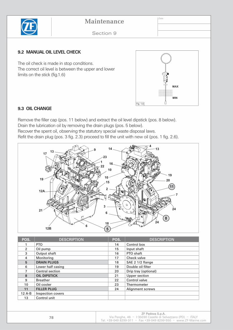
9.2 MANUAL OIL LEVEL CHECK
The oil check is made in stop conditions.The correct oil level is between the upper and lowerlimits on the stick (fig.1.6)
9.3 OIL CHANGE
Remove the filler cap (pos. 11 below) and extract the oil level dipstick (pos. 8 below). Drain the lubrication oil by removing the drain plugs (pos. 5 below).Recover the spent oil, observing the statutory special waste disposal laws. Refit the drain plug (pos. 3 fig. 2.3) proceed to fill the unit with new oil (pos. 1 fig. 2.6).
13
19
20
11
7
414
16
10
2
3
6
18
5
8
6
15
10
1
91317
19
12A
12B
22
21
23
24
24
POS. DESCRIPTION POS. DESCRIPTION 1 PTO 14 Control box 2 Oil pump 15 Input shaft 3 Output shaft 16 PTO shaft4 Monitoring 17 Check valve5 DRAIN PLUGS 18 SAE 2 1/2 flange6 Lower half casing 19 Double oil filter 7 Central section 20 Drip tray (optional)8 OIL DIPSTICK 21 Upper section 9 Breather 22 Control valve 10 Oil cooler 23 Thermometer 11 FILLER PLUG 24 Alignment screws
12 A-B Inspection covers 13 Control unit
Maintenance
Section 9

Date
ZF Padova S.p.A.Via Penghe, 48 – I-35030 Caselle di Selvazzano (PD) – ITALY
Tel. +39-049 8299-311 – Fax +39-049 8299-550 – www.ZF-Marine.com79
9.4 CHANGING THE OIL FILTER
Note: The contamination indicator monitors the filter side during operation, as shown by the posi-tion of the selector lever lock. The flow transfer valve must be switched before carrying out filter maintenance. At this point the contamination indicator signal is reset so the red button can be released again.
1. Activate the pressure equalisation lever and hold it in position; the lever is located in the selector lever Swivel commutation lever. Engage the lock on the right-hand side nearest to the filter.
Place the drip tray underneath to collect oil that flows out.
2. Loosen bleeder screw [1] of the unused filter side by 2-3 turns; fully out for backward motion up against the safety stop.
3. Unscrew the filter grit trap anti-clockwise and clean thoroughly.
4. Remove the filter element with a sideways movement.
5. Check the O-ring on the filter’s grit trap for possible signs of damage and renew if necessary.
6. Ensure the part number of the spare corresponds with the number on the filter label. Open the plas-tic bag and push the element onto the part inside the filter head. Now remove the plastic bag.
7. When installation is complete, tighten the grit trap by turning it clockwise as far as it will go. Unscrew the grit trap by between a 1⁄4 and 1⁄2 turn.
8. To fill the filter chamber, activate the pressure equalisation lever until the oil flows out from the bleed hole without bubbles.
9. Tighten the bleed screw. Check that the filters are not leaking by activating the pressure equali-sation lever again.
Maintenance
Section 9

Date
ZF Padova S.p.A.Via Penghe, 48 – I-35030 Caselle di Selvazzano (PD) – ITALY
Tel. +39-049 8299-311 – Fax +39-049 8299-550 – www.ZF-Marine.com80
9.5 OIL COOLER CHECK
The most common types of problem caused by leakage of coolant from the tubes are corrosion and erosion.The cooling tubes are coated with copper-nickel 90/10; this type of treatment is seawater resistant although not in all working conditions.We therefore strongly recommend observing the following instructions to avoid the risk of erosion / corrosion of the oil cooler.
1. Start-up:
• Make sure the anode is not corroded. The anode must be renewed when more than 60% is corroded.
(See the maintenance program).
2. Maintenance
Periodic checksPeriodic checks of the device are required to guarantee its safe and reliable operation through time. As a general rule greater attention must be directed towards the water-side of the circuit; the oil side is less susceptible to contamination so checks can be carried out as recommended by the experience of the operator.The following checks should be carried out:• When working with seawater the sacrificial anodes installed in the hoods/covers should be
checked at 3-monthly intervals in the initial phase. If they are excessively eroded they must be renewed. If the anodes deteriorate too rapidly, check the water quality.
• The water side of the device must be cleaned at least once a year; it is essential to avoid exces-sive contamination of the tubes. The hoods can be removed without depressurisation of the casing side. Increase the frequency of checks if operations in ports or other places with contami-nated seawater are protracted, in accordance with the requirements of the operator.
• The device must be subjected to an exterior visual inspection at more frequent intervals to iden-tify possible leaks or similar problems in good time. By means of the double loop closure leaks can be pinpointed and the relative magnitude can be estimated.
DisassemblyAdhere to this procedure for disassembly of the device:• Close all pipelines• Empty the device from the tube side. If you need to remove the tube core empty also the casing
side.• Remove the pipes from the tube side.• Remove hoods/covers. To perform this step loosen the 4 screws located at the joint between
dood/main body.
Maintenance
Section 9

Date
ZF Padova S.p.A.Via Penghe, 48 – I-35030 Caselle di Selvazzano (PD) – ITALY
Tel. +39-049 8299-311 – Fax +39-049 8299-550 – www.ZF-Marine.com81
There are 4 fixing plates or washers between hood and cover; these must be returned to the same position at the time of reassembly. For this purpose check the mark on the flange of the main body.
• If disassembly is carried out without removing the tube core, first disassemble the hood/cover without fixing plates to ensure that the tube core is not dislodged. Now remove the fixing plates. This operation can be performed with the aid of a second set of fixing plates, or with other similar means.
Disassembly without removing the tube core:• Remove the O-rings from the external grooves of the tube plates and fix the tube core to the
main body with four screws and the four fixing plates in the middle groove of the tube plates. Using this method the tube side can be inspected and cleaned mechanically. The casing side remains pressurised.
Disassembly of the tube with removal of the tube core:• Remove the O-rings from the external grooves of the tube plates. The fixed position in relation
to the main body is marked on one of the tube plates. A mark “X” indicating the mid point is present on the front side of the tube plate and on the adjacent flange of the main body. Check the position of this symbol. Push the tube (using specific tools if necessary) sideways until the O-ring of the internal groove is visible. Remove the O-ring from the internal groove. Extract the tube core in the opposite direction. Carefully remove the tube core from the main body taking care not to damage the fins. As far as possible keep the tube core suspended by means of wide lifting webbing. Take care not to damage the O-ring seating grooves.
• When removing devices fixed in a vertical direction, always make sure that the tube core does not slip downwards once the fixing plates have been removed. It is good practice to have an extra set of fixing plates and start the disassembly operation from the part on which there are no fixing plates. In this case first of all fix the roll. After having removed the second hood, you can remove the roll (proceed with caution). At the time of reassembly you can use just one set of fixing plates (the set on the symbols side).
AssemblyTo assembly the unit perform the disassembly steps in reverse sequence. Take account also of the following considerations:• It is normal practice to use new O-rings and clean the grooves before fitting them.• Take note of the symbol to ensure the tube core is assembled correctly (X).• Take not of the symbol to assemble the fixing plates correctly (F).• The closing strips are located on the tube core side. Remove the strips only if damaged. When
inserting the tube core ensure that the closing strips have not been moved or twisted. Before assembling the tube core, grease the closing strips. The operating product can be used. The closing strips must ensure an efficient seal around the entire length of the tube core.
• Lubricate the O-rings with a suitable grease.• While inserting the tube plate in the closing location, ensure the O-rings are not severed.
Maintenance
Section 9

Date
ZF Padova S.p.A.Via Penghe, 48 – I-35030 Caselle di Selvazzano (PD) – ITALY
Tel. +39-049 8299-311 – Fax +39-049 8299-550 – www.ZF-Marine.com82
The hoods/covers must be fitted in parallel on the tube plate and pushed uniformly onto the O-ring: ensure the O-ring is not severed during this operation.• With two-stroke devices arrange the plastic separation strip on the side of the hood with the two
connections. This done, install also the fixing plates from the same side.• When assembling the two-stroke hood ensure that the separation plate is fitted correctly.• Continue as described in “Operation”.
CleaningIn the presence of a small quantity of scaling, the tube can be cleaned mechanically. Disassemble the device as described in the disassembly chapter, without removing the tube core, and use a suitable nylon bristle brush to clean the tubes inside (do not use metal wire brushes). Now flush the unit with water. Never use force to prise out trapped deposits or large size debris.In the presence of trapped deposits, use a chemical system to clean the tube core. The proce-dure can be performed by flushing the tube when the device is assembled or by submerging it in chemical solution when disassembled.
This cleaning operation should be carried out exclusively by a specialised technician. Use exclu-sively suitable solvents. Construct the attached list to find the most suitable product. Analyse the material of the plastic separation strip and the O-rings when the device is assembled. The “Con-tacts” section of this manual contains a list of companies that handle products that are suitable in relation to the parts, or that offer complete cleaning services. If the eleventh letter of the type code is à “C” (e.g: KS12-BCN-821C L1000), this indicates that the tube core is coated. To prevent the corrosion damage of the tube core, it is internally coated in the tube and in the tube header plate. During disassembly of the roll and during cleaning procedures, tale care to ensure the coating is not damaged. Use exclusively nylon bristle cleaning brushes and cleaning products in compliance with the applicable regulations. If in doubt concerning a specific product, consult our maintenance department.
TroubleshootingEfficiency is too low! / oil outlet temperature is too high!• Check that all temperatures and materials comply with the project specifications.• Check that there is no foreign matter in the pipe or in the device, such as to create an obstruc-
tion.• Check that the tube core is correctly assembled; check the symbols.• Check that the plastic strips and fixing plates are correctly assembled in the two-stroke hood.• Check that air has been bled completely from all the compression chambers.• Check that the tube side or the casing side are not excessively fouled (with excessively dense
product deposits).• Check that no more than 10% of the tubes are clogged.
Leakages from the tubesIf you think there are leaks from the tubes, proceed as illustrated in the section concerning “disas-sembly without removing the tube core”. The casing part can remain pressurised. After having cleaned the tube plates you will be able to identify the leaking tube by the condition of the liquid
Maintenance
Section 9
Date
ZF Padova S.p.A.Via Penghe, 48 – I-35030 Caselle di Selvazzano (PD) – ITALY
Tel. +39-049 8299-311 – Fax +39-049 8299-550 – www.ZF-Marine.com83
that comes out. Close both ends of the tube with conical plugs made of copper or hardwood. You can plug a maximum of 10% of the tubes without any significant loss of efficiency. It is possible to remove the defective tube.
Leaks from the rolled jointsIf you notice a leak from a rolled joint while checking for leaks from a tube, you can roll the part again by means of a special tool. Note however that this procedure should always be performed by specialised personnel. Since these defects are relatively uncommon, we recommend having the entire tube core checked at our works.
Leaks from the O-ringsIf you notice a leak between the hood/cover and the main body, this indicates that one of the O-rings of the tube plate is defective. The type of substance emerging identifies the groove of the tube plate in which the defect has occurred. If the defect is on the tube side, proceed as illustrated in the section concerning “disassembly without removing the tube core”. If the defect is from the side of the casing, proceed as described in the part relative to “disassembly with removal of the tube core”. In this case there is no need to remove the tube core completely from the main body. Assemble the O-ring as illustrated in the part relative to “Assembly”.
3. Standstill periods:
When the installation is at a standstill for a period of:• Less than two days
Water flow within range that on average complies with operation of the pump (see table)• More than two days
Water flow for minimum period of one hour• More than two weeks
The water circuit must be drained and flushed with fresh water.
Technical data: see installation drawings and oil cooler manual and the technical data given in this manual
Maintenance
Section 9
Date
ZF Padova S.p.A.Via Penghe, 48 – I-35030 Caselle di Selvazzano (PD) – ITALY
Tel. +39-049 8299-311 – Fax +39-049 8299-550 – www.ZF-Marine.com84
Remarks
_________________________________________________________________________________________________
_________________________________________________________________________________________________
_________________________________________________________________________________________________
_________________________________________________________________________________________________
_________________________________________________________________________________________________
_________________________________________________________________________________________________
_________________________________________________________________________________________________
_________________________________________________________________________________________________
Maintenance
Section 9

Section 10


Date
ZF Padova S.p.A.Via Penghe, 48 – I-35030 Caselle di Selvazzano (PD) – ITALY
Tel. +39-049 8299-311 – Fax +39-049 8299-550 – www.ZF-Marine.com87
Troubleshooting Remedies
Section 10
Troubleshooting Remedies
10.1 Possible faults
MALFUNCTIONS CAUSES REMEDY
Overheating Oil level is too high
Lubricating oil pressure too low (insufficiently cooled oil)
Gearbox is overloaded
Operating oil pressure is too low (clutch is slipping)
Excessive pump pressure
Oil does not flow back from the outer bearing sides
Bearings damaged
Cooling water flow not enough
Correct oil level
Re-set operating oil pressure to the lowest permitted value
Reduce input power
Regulate operating pressure(see 2-stage valve)
Clean the filter
Install end covers or seal covers in such a way that the oil can flow back
Replace damaged bearings
Check the water flow

Date
ZF Padova S.p.A.Via Penghe, 48 – I-35030 Caselle di Selvazzano (PD) – ITALY
Tel. +39-049 8299-311 – Fax +39-049 8299-550 – www.ZF-Marine.com88
MALFUNCTIONS CAUSES REMEDY
Lack of oil pressure Wrong direction of rotation
Filter obstructed
Oil level too low
The viscosity of the oil is too low
Oil temperature too high
Suction pipe obstructed
Pump drive is defective
Pump wear
Selector position is not correct
Wear of the oil supply
Reverse engine rotation or reconstruct gearbox for other direction of rotation
Clean filter
Refill with oil and trace cause of oil loss
Change to an oil conforming to the “recommended lubricants”
See “Excessive gearbox temperature”
Clean suction pipe
Renew the pump drive
Install new pump
Adjust remote control operation
Renew oil supply
Oil leakage Drain plug is not tight
Dipstick connector not tight
High-pressure system leaking
Oil loss through the air vent
Mating faces of the housings are not sealed
Leakage of the shaft seals
Oil cooler is leaking
Replace the gasket and tighten drain plug
Replace dipstick gasket and tighten
Tighten all fittings
Check oil splash plate under the air vent
Seal with new compound and tighten all bolts
a) Renew sealsb) Install sealing cover in sucha manner that the passage is free from the outer bearing sidec) Clean seals
Replace the cooler insert
Troubleshooting Remedies
Section 10
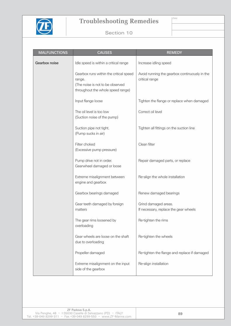
Date
ZF Padova S.p.A.Via Penghe, 48 – I-35030 Caselle di Selvazzano (PD) – ITALY
Tel. +39-049 8299-311 – Fax +39-049 8299-550 – www.ZF-Marine.com89
MALFUNCTIONS CAUSES REMEDY
Gearbox noise Idle speed is within a critical range
Gearbox runs within the critical speed range.(The noise is not to be observed throughout the whole speed range)
Input flange loose
The oil level is too low(Suction noise of the pump)
Suction pipe not tight.(Pump sucks in air)
Filter choked(Excessive pump pressure)
Pump drive not in order.Gearwheel damaged or loose
Extreme misalignment between engine and gearbox
Gearbox bearings damaged
Gear teeth damaged by foreign matters
The gear rims loosened by overloading
Gear wheels are loose on the shaft due to overloading
Propeller damaged
Extreme misalignment on the input side of the gearbox
Increase idling speed
Avoid running the gearbox continuously in the critical range
Tighten the flange or replace when damaged
Correct oil level
Tighten all fittings on the suction line
Clean filter
Repair damaged parts, or replace
Re-align the whole installation
Renew damaged bearings
Grind damaged areas.If necessary, replace the gear wheels
Re-tighten the rims
Re-tighten the wheels
Re-tighten the flange and replace if damaged
Re-align installation
Troubleshooting Remedies
Section 10

Date
ZF Padova S.p.A.Via Penghe, 48 – I-35030 Caselle di Selvazzano (PD) – ITALY
Tel. +39-049 8299-311 – Fax +39-049 8299-550 – www.ZF-Marine.com90
MALFUNCTIONS CAUSES REMEDY
The propeller does not stop turning in “Neutral”
The vessel is still moving
The propeller is being driven by a current
Gearbox controller is not properly in the “stop” position
Defective gearbox controller (Uncontrolled oil to one clutch)
Clutch plates broken
Seal damaged, sticking piston
Splines of the clutch damaged
Release springs not working
Oil to cold
Wait until it is at a complete standstill
Wait until it is at a complete standstill
Adjust the remote control
Replace gearbox controller
Renew clutch plates
Renew seals
Re-work the teeth or renew the parts
Clean the clutch.Replace the springs if necessary
Recommended given operating temperature
Lubricating 50° - 70° …40° - 50°
The engine stalls during reversing
When switching over, the engine threatens to stall, at this manoeuvre the engine must be “caught” by fuel admission so that the power taken from the propeller will not be larger than the engine power at this moment.
The idling speed is too low
The operating pressure is too high, therefore, engagement is too quick
The gearbox controller is defective (uncontrolled oil flow to one clutch)
Clutch plates are damaged
The splines of the clutch are damaged
The release springs do not work
Piston of the clutch is jammed,seals are damaged
Increase the idling speed
Reduce the operating pressure to normal value
Replace gearbox controller
Replace damaged clutch plates
Re-work the splines or renew the parts (check for critical speed range)
Clean the clutch.Replace the springs if necessary
Renew damaged seals
Troubleshooting Remedies
Section 10

Section 11


Date
ZF Padova S.p.A.Via Penghe, 48 – I-35030 Caselle di Selvazzano (PD) – ITALY
Tel. +39-049 8299-311 – Fax +39-049 8299-550 – www.ZF-Marine.com93
Service Centres
Section 11
Service Centres
ARGENTINA TRANSMISIONES MARINAS S.A.Ing. Daniel CanouraHernandarias 3656 - B7603GNH Mar Del PlataARGENTINATel. +54 223 4807174Fax +54 223 4807174E-mail: [email protected]
AUSTRALIA ZF AUSTRALIA PACIFIC Pty Ltd.14 Lidco Street - Arndell Park NSW 2148AUSTRALIATel. +61 2 9679 5555Fax +61 2 9679 5500E-mail: [email protected]
ZF DO BRASIL Ltda *Avenida Conde Zeppelin, 1935CEP 18103-905 Sorocaba-SPBRASILTel. +55 15 4009 2389Fax +55 15 4009 2233E-mail: [email protected]
BRAZIL
BELGIUMBENELUXLUXEMBURGNETHERLANDS
ADS VAN STIGTAvelingen West 30 - 4202 MS GorinchemNETHERLANDSTel. +31 183 650 000Fax +31 183 650 001E-mail: [email protected]
CHILE EQUIPAMIENTO MARINO LTDA.Rafael Correa 1268, VitacuraSantiago de ChileCHILEP.R. CHINATel./Fax +56 2 415 8737Mob. +56 9 997 5059E-mail: [email protected]
ZF PADOVA SHANGHAIREPRESENTATIVE OFFICE
No. 600 Luban RoadRoom 2206-08, Jiangnan Building
Shanghai, 200023P.R. CHINATel. +86 21 6301 4338Fax +86 21 6301 6449E-mail: [email protected]
FOILBORNE ENGINEERING Ltd.
Veristrong Ind. Ctr. - 34-36 Au Pui Wan St.Unit A8-9, 13/F
Fotan, ShatinN.T. Hong KongTel. +852 2 687 2988Fax +852 2 687 1996E-mail: [email protected]
CROATIA
CHINA
ITEC d.o.o.Ul. Kneza Domagoja 1047000 KarlovacCROATIATel. +385 47 631 755Fax +385 47 631 756E-mail: [email protected]
CYPRUS CHAR. (INDUSTRIAL)PILAKOUTAS Ltd.**7, Larnaca Street - 1503 NicosiaCYPRUSTel. +357 22 349 572Fax +357 22 349 952E-mail: [email protected]
DENMARK ZF DANMARK ApSTaastrupgaardsvej 8-102630 TaastrupDENMARKTel. +45 7022 6243Fax +45 7022 2643E-mail: [email protected]
ECUADOR COPRIMARSAKM 12.5 Vía a Daule Urb.Colina del Sol Mz. 2021 V. 5ECUADORTel. +59 3 9 961 3032Fax +59 3 9 702 0468E-mail: [email protected] also U.S.A.
BALTIC MARINE GROUP ASPaljassaare tee 1410313 TallinnESTONIATel. +372 68 333 00Fax +372 68 333 01E-mail: [email protected]
ATOY OYLauttasaarentie 5400200 HelsinkiFINLANDTel. +358 9 682 71Fax +358 9 682 73 05E-mail: [email protected]
ZF FRANCE S.a.r.l. 3-11 Rue Henri Poincaré92 167 Antony CedexFRANCETel. +33 1 4096 4265Fax +33 1 4096 4285E-mail: [email protected]
GERMANY
ESTONIA
FINLAND
ZF MARINE GmbH * Ehlersstr. 5088046 FriedrichshafenGERMANYTel. +49 7541 77 2207Fax +49 7541 77 4222E-mail: [email protected]
ZF MARINE GmbH
Zamdorferstrasse 90Representative Office
81677 MünchenGERMANYTel. +49 89 930 094 63/64Fax +49 89 930 094 21E-mail: [email protected]
FRANC

Date
ZF Padova S.p.A.Via Penghe, 48 – I-35030 Caselle di Selvazzano (PD) – ITALY
Tel. +39-049 8299-311 – Fax +39-049 8299-550 – www.ZF-Marine.com94
SCHIFFSDIESELTECHNIK KIELGrasweg 26 b24118 KielGERMANYTel. +49 431 544 420Fax +49 431 544 4220E-mail: [email protected]
TEKMAR Ltd.15 Ethn. Makariou Str.18 547 Neofaliro. PiraeusGREECETel. +30 210 4820 814Fax +30 210 4811 803E-mail: [email protected]
GREECE
K. & E. MALERDOS Co.20, Ymittou str18 540 PiraeusGREECETel. +30 210 417 9693Fax +30 210 417 5441E-mail: [email protected]
ARIEXPO S.A.68, Alimou Avenue, Alimos 17 455 AthensGREECETel. +30 210 984 3863Fax +30 210 983 1346E-mail: [email protected]
INDIA LOURENCO MARINEG-20 Lina Residency, FatordaMargao - Goa 403 602INDIATel. +91 832 2743 468Fax +91 832 2743 450E-mail:[email protected]
INDONESIA
ISRAEL
P.T. TESCO INDOMARITIMJulan Tuiodong Bawah X No. 17Jakarta Selatan 12190INDONESIATel. +62 21 5260 363 - 67Fax +62 21 5260 369E-mail: [email protected]
NIMDA Co. Ltd.Lev Pesach StreetNorth Industrial Zone - Lod 71293ISRAELTel. +972 8 9781 111Fax +972 8 9781 137E-mail: [email protected]
ZF PADOVA S.p.A. *(ZF MARINE HEADQUARTERS) Via Penghe, 4835030 Caselle di Selvazzano (PD)ITALYTel. +39 049 8299 311Fax +39 049 8299 550E-mail: [email protected]
ZF MARINE ARCO S.p.A. *Via S. Andrea, 1638062 Arco (TN)ITALYTel. +39 0464 580 555Fax +39 0464 580 544E-mail: [email protected]
ZF ITALIA S.r.l.Via Donizetti, 1120090 Assago (MI)ITALYTel. +39 02 4888 31Fax +39 02 4884 3807E-mail: [email protected]
JAPAN ZF JAPAN Co., Ltd.Palazzo Astec 7, 8F2-8-1, Higashi Shimbashi,Minato-kuTokyo 105-0021JAPANTel. +81 3 4590-7700Fax +81 3 4590-7770E-mail: [email protected]
KOREA (South) ZF KOREA Co. Ltd.422-2 Chongchon-dongBupyong-GuIncheon 403-032Rep. of KOREATel. +82 32 5051 508Fax +82 32 5051 514E-mail: [email protected]
MALAYSIA ZF SALES & SERVICE(MALAYSIA) Sdn. Bhd.No. 12, Jalan Teknologi 3/1Seksyen 3 Kota Damansara47810 Petaling JayaSelangor Darul EhsanMALAYSIATel. +60 3 6157 8856Fax +60 3 6157 9648E-mail: [email protected]
AJENSI TULEN Sdn. Bhd.35A Jalan Anggerek 36Johore Bahru, JH 81100MALAYSIATel. +60 7 3547 755Fax +60 7 3547 757E-mail: [email protected]
MALTA OCEANS9, Main StreetZurrieq ZRQ 03MALTATel. +356 21 640 703Fax +356 21 641 223E-mail: [email protected]
NORWAY KGK NORGE ASCaspar Storms vei 190664 OsloNORWAYTel. +47 22 88 4680Fax +47 22 72 0902E-mail: [email protected]
PERU PGO INTERNATIONAL S.A.C.Av. Arequipa 2450, Of. 1108Lima 14PERUTel. +51 1 421 6055Fax +51 1 421 6664E-mail: [email protected]
ITALY
PIENING PROPELLER
Am Altendeich 83Otto Piening GmbH
25348 GlückstadtGERMANYTel. +49 4124 9168 0Fax +49 4124 3716E-mail: [email protected]
Service Centres
Section 11

Date
ZF Padova S.p.A.Via Penghe, 48 – I-35030 Caselle di Selvazzano (PD) – ITALY
Tel. +39-049 8299-311 – Fax +39-049 8299-550 – www.ZF-Marine.com95
RUSSIA
SINGAPORE
ZF MARINE RUSSIASuite 404 - Obvodny Kanal Emb., 118190005 St. PetersburgRUSSIATel. +7 812 441 37 94Fax +7 812 441 37 94E-mail: [email protected]
ZF SOUTH EAST ASIA Pte. Ltd.
638678 Singapore11 Tuas Drive 1
Rep. of SINGAPORETel. +65 6424 8787Fax +65 6424 8788E-mail: [email protected]
SOUTH AFRICA ZF of SOUTH AFRICA (Pty.) Ltd.Meadowdale Ext. 3170 Herman Road1401 Germiston JohannesburgRep. of SOUTH AFRICATel. +27 11 457 0000Fax +27 11 453 7506E-mail: [email protected]
SPAIN ZF ESPAÑA, S.A.Avenida Fuentemar, 1128820 Coslada (Madrid)SPAINTel. +34 91 485 2698Fax +34 91 485 0036E-mail: [email protected]
SWEDEN KG KNUTSSON ABTRANSMISSIONSDIVIONENNottingham NG7 2SXUNITED KINGDOMTel. +44 115 986 9211Fax +44 870 460 1479E-mail: [email protected]
THAILAND SEA SYSTEMS Co., Ltd.477, Moo 2, Taiban RoadTumbol Taiban, Ampur MuangSamutprakan 10280THAILANDTel. +66 2 703 3013-15Fax +66 2 703 4044E-mail: [email protected]
ZF GREAT BRITAIN Ltd.Abbeyfield Road, LentonNottingham NG7 2SX UNITED KINGDOMTel. +44 115 986 9211Fax +44 870 460 1479E-mail: [email protected]
KG KNUTSSON ABTRANSMISSIONSDIVISIONENHammarbacken 819181 SollentunaSWEDENTel. +46 8 923 000Fax +46 8 929 599E-mail: [email protected]
ZF MARINE MIDDLE EAST LLC502 & 503, Golden TowerBuhaira CornicheSharjahU.A.E.Tel. +971 6 574 7074Fax +971 6 574 7174E-mail: [email protected]
UNITEDARABEMIRATES
ZF MARINE, LLC (U.S. HEADQUARTERS Pleasure Craft, PropulsLatin America, Caribbean, After Market)3131 Southwest 42nd StreetFort Lauderdale, FL 33312U.S.A.Tel. +1 954 581 4040Latin America: +1 954 581 4063Fax +1 954 581 4078-77E-mail: [email protected]
ZF MARINE, LLC West Coast(Commercial and Fast Craft)12125 Harbor Reach Drive, Ste. B Mukilteo, WA 98275U.S.A.Tel. +1 425 583 1900Fax +1 425 493 1579Toll Free: 800 546 5455E-mail: [email protected]
U.S.A.MEXICO
SISTEMAS DE PROPULSIONAvda 67 A, entre 149B y 150Municipio San Francisco, Maracaibo, Estado ZuVENEZUELATel. +58 261 736 0747Fax +58 261 736 0746E-mail: [email protected]
VENEZUELA
UNITEDKINGDOM
MANUFACTURING LOCATIONS
ZF HURTH MARINE REPRESENTATIVE ONLY***
POLAND VOLVO PENTA POLSKA sp.z o.o.Prostokatna 5A Str.81-601 GydniaPOLANDTel. +48 58 627 3380Fax +48 58 627 3390E-mail: [email protected]: [email protected]
TURKEY NIVEKO MAKINA TICARETLtd. Takkeci Sokak No. 380820 Arnavutköy - Istanbul TURKEY Tel. +90 212 2872780Fax +90 212 2876571E-mail: [email protected]
Service Centres
Section 11
Date
ZF Padova S.p.A.Via Penghe, 48 – I-35030 Caselle di Selvazzano (PD) – ITALY
Tel. +39-049 8299-311 – Fax +39-049 8299-550 – www.ZF-Marine.com96
Service Centres
Section 11

Section 12