008GTi May 92009 USB- TurboTenna - · PDF filedistributed without any warranty and are subject...
21
008GTi USB- TurboTenna May 9 2009 This manual walks though the steps of setting up the USB-TurboTenna Plug & Play WiFi antenna from quick start to detailed explanation of what each parameter does. It talks about the STATION mode for accessing a hotspot afar, and using the USB-TurboTenna as a local ACCESS POINT for sharing the Internet with other WiFi enabled client computers. Instruction Manual Version 0.212.2
Transcript of 008GTi May 92009 USB- TurboTenna - · PDF filedistributed without any warranty and are subject...
008GTi USB-
TurboTenna
May 9
2009This manual walks though the steps of setting up the USB-TurboTenna Plug & Play WiFi antenna from quick start to detailed explanation of what each parameter does. It talks about the STATION mode for accessing a hotspot afar, and using the USB-TurboTenna as a local ACCESS POINT for sharing the Internet with other WiFi enabled client computers.
Instruction Manual Version 0.212.2
008GTi USB-TurboTenna Instruction Manual
© 2009 by danets Datacom Network Ltd. All rights reserved. DN-WLAN-032 Page 2
Copyright© by danets Datacom Network Ltd. all rights reserved. No part of this publication may be reproduced, transmitted, transcribed, stored in a retrieval system, or translated into any language or computer language, in any form or by any means, electronic, mechanical, magnetic, optical, chemical, manual or otherwise, without the prior written permission of this Company .This company makes no representations or warranties, either expressed or implied, with respect to the contents hereof and specifically disclaims any warranties, merchantability or fitness for any particular purpose. Any software described in this manual is sold or licensed "as is". Should the programs prove defective following their purchase, the buyer (and not this company, its distributor, or its dealer) assumes the entire cost of all necessary servicing, repair, and any incidental or consequential damages resulting from any defect in the software. Further, this company reserves the right to revise this publication and to make changes from time to time in the contents hereof without obligation to notify any person of such revision or changes. The software and specifications are subject to change without notice. Please visit our web site www.danets.com for the update. All rights reserved including all brand and product names mentioned in this manual are trademarks and/or registered trademarks of their respective holders Linux Open Source Code Certain danets products include software code developed by third parties, software code is subject to the GNU General Public License ("GPL") or GNU Lesser General Public License ("LGPL"). Please see the GNU (www.gnu.org) and LPGL(www.gnu.org) Websites to view the terms of each license. The GPL Code and LGPL Code used in danets products are distributed without any warranty and are subject to the copyrights of their authors. For details, see the GPL Code and LGPL Code licenses. You can download the firmware-files at http://www.danets.com under "Support" page.
008GTi USB-TurboTenna Instruction Manual
© 2009 by danets Datacom Network Ltd. All rights reserved. DN-WLAN-032 Page 3
Table of Contents
1. PACKING LIST ............................................................................................................................................................................... 4
2. QUICK START ................................................................................................................................................................................ 4
2.1 INSTALLATION AND DEVICE CONNECTION ......................................................................................................................................... 4 2.2 CHOICE OF LOCATION ........................................................................................................................................................................... 4 2.3 ADJUSTMENT ........................................................................................................................................................................................ 4
3. SCANNING THE WIFI SIGNAL ................................................................................................................................................ 5
4. USB WIRELESS LAN UTILITY ................................................................................................................................................. 7
4.1 (A) MAIN MENU ................................................................................................................................................................................... 7 4.1.1 Refresh (R) .............................................................................................................................................................................. 7 4.1.2 Set Wizard (S) ........................................................................................................................................................................ 7
4.2 (B) ADAPTER LISTING AREA ............................................................................................................................................................... 8 4.3 [C] PROPERTIES AREA ......................................................................................................................................................................... 8 4.4 [D] GLOBAL CONTROL BAR ................................................................................................................................................................ 8
5. ADVANCED SETTING OPTIONS (STATION MODE] ........................................................................................................ 9
5.1 GENERAL ............................................................................................................................................................................................. 9 5.1.1 Status .......................................................................................................................................................................................... 9 5.1.5 SSID ........................................................................................................................................................................................ 10 5.1.6 Signal Strength .................................................................................................................................................................. 10 5.1.7 Link Quality ........................................................................................................................................................................... 10 5.1.8 Throughput Diagram ....................................................................................................................................................... 10 5.1.9 Network Address group ................................................................................................................................................ 10 5.1.10 Renew IP button ............................................................................................................................................................. 10
5.2 PROFILE ........................................................................................................................................................................................... 10 5.2.1 Add .......................................................................................................................................................................................... 10 5.2.2 Remove ................................................................................................................................................................................. 11 5.2.3 Edit ........................................................................................................................................................................................... 11 5.2.4 Duplicate ............................................................................................................................................................................... 11 5.2.5 Set Default ........................................................................................................................................................................... 11
5.3 AVAILABLE NETWORK ............................................................................................................................................................. 11 5.3.1 Refresh .................................................................................................................................................................................. 11 5.3.2 Add to Profile ...................................................................................................................................................................... 11
5.4 ADVANCED .................................................................................................................................................................................... 12 5.4.1 Power Save .......................................................................................................................................................................... 12 5.4.2 Wireless Mode .................................................................................................................................................................. 12 5.4.3 Channel Plan ....................................................................................................................................................................... 12 5.4.4 Preamble Mode ................................................................................................................................................................. 12 5.4.5 Fragment Threshold ........................................................................................................................................................ 13 5.4.6 RTS Threshold .................................................................................................................................................................... 13 5.4.7 WWM Parameters ......................................................................................................................................................... 13
5.5 STATUS ............................................................................................................................................................................................ 13 5.6 STATISTICS .................................................................................................................................................................................... 14 5.7 WIFI PROTECT SETUP ................................................................................................................................................................ 14
6. ADVANCED SETTING OPTIONS (ACCESS POINT MODE] ........................................................................................ 16
6.1 GENERAL ......................................................................................................................................................................................... 16 6.1.1 SSID ........................................................................................................................................................................................ 16 6.1.2 BSSID ..................................................................................................................................................................................... 16 6.1.3 CONFIG .................................................................................................................................................................................. 16
6.2 ADVANCED .................................................................................................................................................................................... 17 6.2.1 Beacon Interval .................................................................................................................................................................. 17 6.2.2 DTIM Period ........................................................................................................................................................................ 17 6.2.3 Premeable Mode .............................................................................................................................................................. 17
6.3 STATISTICS .................................................................................................................................................................................... 18 6.4 INTERNET CONNECTION SHARING [ICS] ...................................................................................................................................... 19
008GTi USB-TurboTenna Instruction Manual
© 2009 by danets Datacom Network Ltd. All rights reserved. DN-WLAN-032 Page 4
1. Packing List
Installation of the USB-TurboTenna is straight forward. As soon as you open up the box, you will be able to find the following items: A USB-TurboTenna High Power Plug & Play antenna with a tripod A USB2.0 extender cable A CD-ROM software drivers for XP/VISTA, Linux and MAC OS X An installation guide
2. Quick Start
2.1 Installation and device connection Install the CD-ROM software drivers before you plug in the USB-TurboTenna antenna to your PC or laptop computer. This avoids the antenna being recognized by another existing WiFi software driver which might not be fully compatible with the antenna’s original software driver. Insert the CD-ROM into the CD/DVD drive of your computer. As soon as the AutoPlay window appears, double click “SETUP.exe” to install the software driver. If the AutoPlay window does not pop up, you could also go to the CD/DVD drive under “My Computer” and double click the SETUP icon. Reboot your computer. Plug in the USB-TurboTenna antenna to a spare USB port of your computer using the USB2.0 cable supplied in the kit.
2.2 Choice of Location You may either setup the antenna on a table or a tall wooden book shelf near the ceiling. Extend the legs of the tripod to maintain stability. Never put the antenna on a metal cabinet or behind a metal structure. If you intend to setup the antenna outdoor such as roof top, balconies, poles or towers, be sure to install an arrestor for lightning protection. Once you have chosen the location, make sure that your RF cable is long enough to each your wireless router or WLAN client adapter device. Point the antenna in the direction of the signal source.
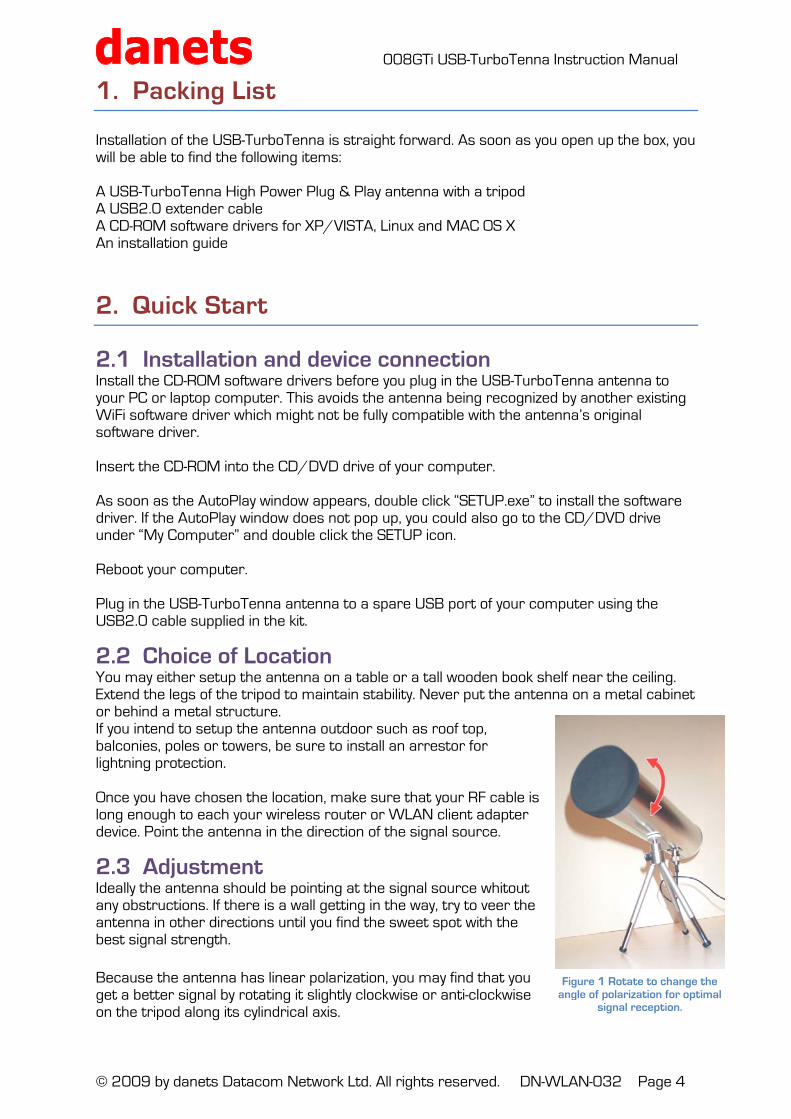
2.3 Adjustment Ideally the antenna should be pointing at the signal source whitout any obstructions. If there is a wall getting in the way, try to veer the antenna in other directions until you find the sweet spot with the best signal strength.
Because the antenna has linear polarization, you may find that you get a better signal by rotating it slightly clockwise or anti-clockwise on the tripod along its cylindrical axis.
Figure 1 Rotate to change the angle of polarization for optimal
signal reception.
008GTi USB-TurboTenna Instruction Manual
© 2009 by danets Datacom Network Ltd. All rights reserved. DN-WLAN-032 Page 5
3. Scanning the WiFi Signal
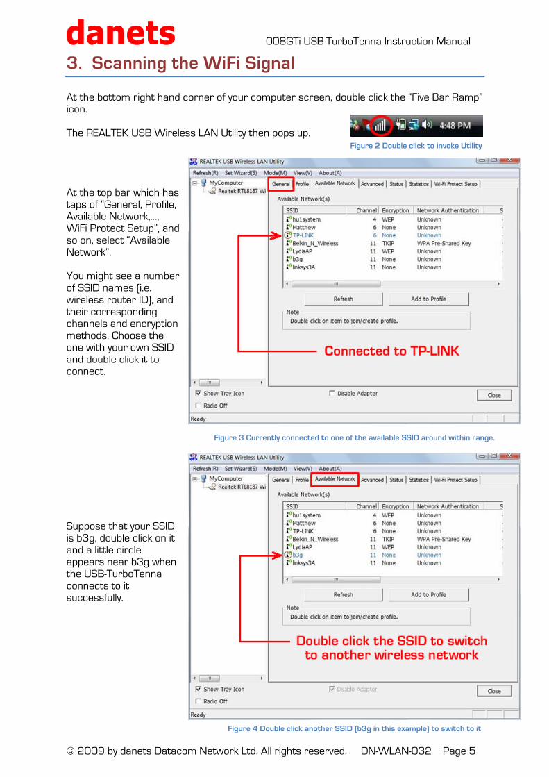
At the bottom right hand corner of your computer screen, double click the “Five Bar Ramp” icon. The REALTEK USB Wireless LAN Utility then pops up. At the top bar which has taps of “General, Profile, Available Network,…, WiFi Protect Setup”, and so on, select “Available Network”. You might see a number of SSID names (i.e. wireless router ID), and their corresponding channels and encryption methods. Choose the one with your own SSID and double click it to connect. Suppose that your SSID is b3g, double click on it and a little circle appears near b3g when the USB-TurboTenna connects to it successfully.
Figure 2 Double click to invoke Utility
Figure 3 Currently connected to one of the available SSID around within range.
Figure 4 Double click another SSID (b3g in this example) to switch to it
008GTi USB-TurboTenna Instruction Manual
© 2009 by danets Datacom Network Ltd. All rights reserved. DN-WLAN-032 Page 6
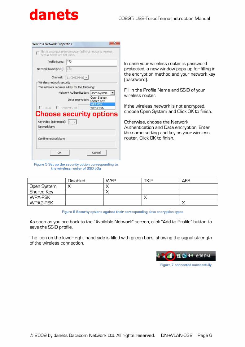
In case your wireless router is password protected, a new window pops up for filling in the encryption method and your network key (password). Fill in the Profile Name and SSID of your wireless router. If the wireless network is not encrypted, choose Open System and Click OK to finish. Otherwise, choose the Network Authentication and Data encryption. Enter the same setting and key as your wireless router. Click OK to finish.
Disabled WEP TKIP AES Open System X X Shared Key X WPA-PSK X WPA2-PSK X
Figure 6 Security options against their corresponding data encryption types
As soon as you are back to the “Available Network” screen, click “Add to Profile” button to save the SSID profile. The icon on the lower right hand side is filled with green bars, showing the signal strength of the wireless connection.
Figure 7 connected successfully
Figure 5 Set up the security option corresponding to the wireless router of SSD b3g
008GTi USB-TurboTenna Instruction Manual
© 2009 by danets Datacom Network Ltd. All rights reserved. DN-WLAN-032 Page 7
4. USB Wireless Lan Utility
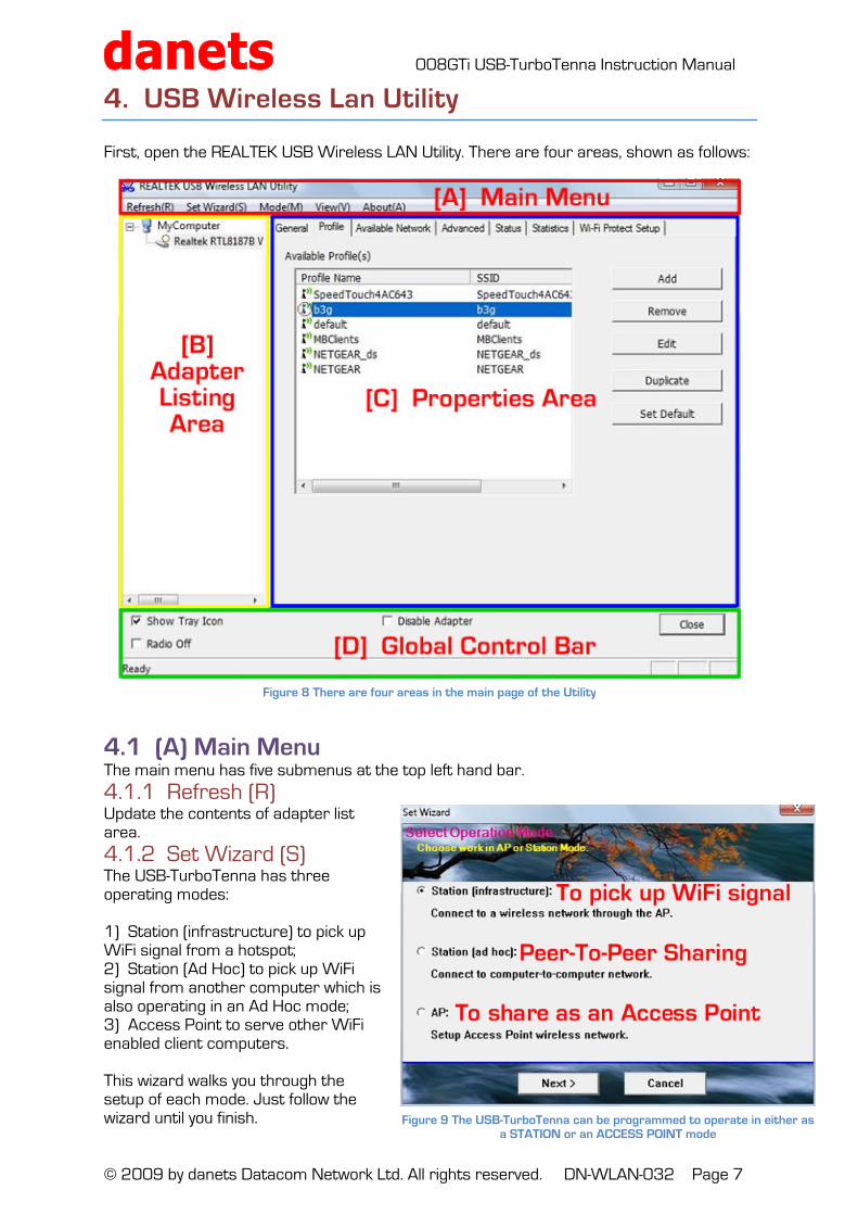
First, open the REALTEK USB Wireless LAN Utility. There are four areas, shown as follows:
4.1 (A) Main Menu The main menu has five submenus at the top left hand bar.
4.1.1 Refresh (R) Update the contents of adapter list area.
4.1.2 Set Wizard (S) The USB-TurboTenna has three operating modes: 1) Station (infrastructure) to pick up WiFi signal from a hotspot; 2) Station (Ad Hoc) to pick up WiFi signal from another computer which is also operating in an Ad Hoc mode; 3) Access Point to serve other WiFi enabled client computers. This wizard walks you through the setup of each mode. Just follow the wizard until you finish.
Figure 8 There are four areas in the main page of the Utility
Figure 9 The USB-TurboTenna can be programmed to operate in either as a STATION or an ACCESS POINT mode
008GTi USB-TurboTenna Instruction Manual
© 2009 by danets Datacom Network Ltd. All rights reserved. DN-WLAN-032 Page 8
4.1.3 Mode (M) Manual setting of the operating mode to Station or Access Point.
4.1.4 View (V) Toggles the Status Bar.
4.1.5 About (A) Shows the version number reference at the bottom of the utility window.
4.2 (B) Adapter Listing Area All USB adapters connected to the computer are shown it this area. You could click on any one of the USB adapters to proceed with setup.
4.3 [C] Properties Area Having selected the USB adapter in the Adapter Listing Area, you may proceed to configure its properties in the Properties Areas which consists of seven submenus, namely: GENERAL PROFILE AVAILABLE NETWORK ADVANCED STATUS STATISTICS WIFI PROTECT SETUP
4.4 [D] Global Control Bar It consists of the following options: 4.4.1 Show Tray Icon – when this box is checked, the management GUI will be minimized and stay on the lower right hand corner of your computer screen. If you uncheck the box and click CLOSE on the bar, the GUI will disappear from the lower right hand corner of the screen and you have to invoke the REALTEK Utility every time you set up the properties of the USB adapter. 4.4.2 Disable Adapter - Turn on and off the USB adapter completely. 4.4.3 Radio Off – Turn off the radio for saving power. When the radio box is checked, the links with other wireless network nodes are disconnected. You should be careful not to check the box when the USB adapter is operating in ACCESS POINT mode, otherwise all the WiFi PC clients shall be disconnected. 4.4.4 Status Bar – At the buttom of the Global Control Bar, it shows READY on the left if the utility is working normally. NUM and CAP are shown on the left hand side when these keys are invoked.
008GTi USB-TurboTenna Instruction Manual
© 2009 by danets Datacom Network Ltd. All rights reserved. DN-WLAN-032 Page 9
5. Advanced Setting Options (STATION Mode]
Remeber that the USB adapter has two operating modes? STATION MODE – pick up WiFi signal from a hotspot or an access point; and ACCESD POINT MODE - to serve other WiFi enabled client computers. Let's talk about the advanced settings of the STATION mode followed by the ACCESS POINT mode. Select STATION under Mode [M] in the Main Menu top bar and let's walk through the submenus of the Properties Area from left to right. GENERAL PROFILE AVAILABLE NETWORK ADVANCED STATUS STATISTICS WIFI PROTECT SETUP
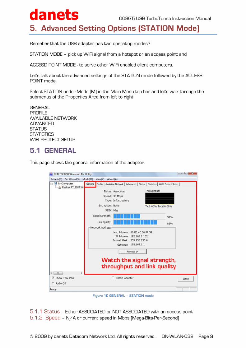
5.1 GENERAL This page shows the general information of the adapter.
5.1.1 Status – Either ASSOCIATED or NOT ASSOCIATED with an access point
5.1.2 Speed – N/A or current speed in Mbps (Mega-Bits-Per-Second)
Figure 10 GENERAL – STATION mode
008GTi USB-TurboTenna Instruction Manual
© 2009 by danets Datacom Network Ltd. All rights reserved. DN-WLAN-032 Page 10
5.1.3 Type – Current wireless LAN configuration type in either INFRASTRUCTURE or AD HOC 5.1.4 Encryption – N/A or current encryption method used 5.1.5 SSID – Shows the name of the wireless network 5.1.6 Signal Strength – An indication of how strong or weak the adapter is picking up the signal from the wireless network. 5.1.7 Link Quality – An indication of the Signal to Noise level. 5.1.8 Throughput Diagram – A chart showing the real time transmitting (TX) and overall traffic (Total) 5.1.9 Network Address group – Shows the MAC address of the USB adapter, whose current IP address, subnet mast and the IP gateway connected to the wireless network. 5.1.10 Renew IP button – Click to obtain a new set of IP address, subnet mast and IP gateway from the wireless network.
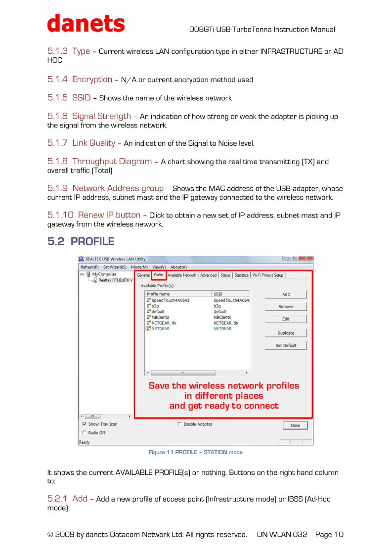
5.2 PROFILE It shows the current AVAILABLE PROFILE(s) or nothing. Buttons on the right hand column to: 5.2.1 Add – Add a new profile of access point (Infrastructure mode) or IBSS (Ad-Hoc mode)
Figure 11 PROFILE – STATION mode
008GTi USB-TurboTenna Instruction Manual
© 2009 by danets Datacom Network Ltd. All rights reserved. DN-WLAN-032 Page 11
5.2.2 Remove – Highlight an existing profile and remove 5.2.3 Edit – Highlight an existing profile and edite 5.2.4 Duplicate – Highlight an existing profile and make a copy of it 5.2.5 Set Default – Highlight an existing profile and set it as Default to establish a wireless connection. When the profile is set as Default, a little red circle appears near the profile name.
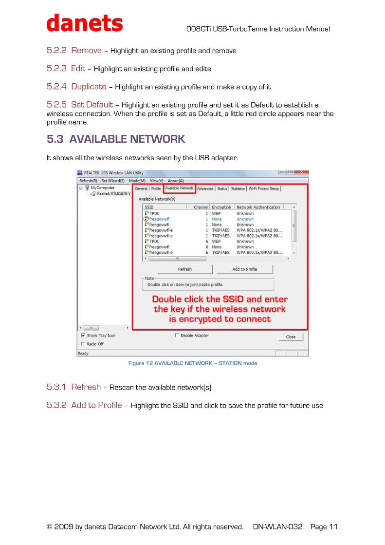
5.3 AVAILABLE NETWORK It shows all the wireless networks seen by the USB adapter. 5.3.1 Refresh – Rescan the available network(s) 5.3.2 Add to Profile – Highlight the SSID and click to save the profile for future use
Figure 12 AVAILABLE NETWORK – STATION mode
008GTi USB-TurboTenna Instruction Manual
© 2009 by danets Datacom Network Ltd. All rights reserved. DN-WLAN-032 Page 12
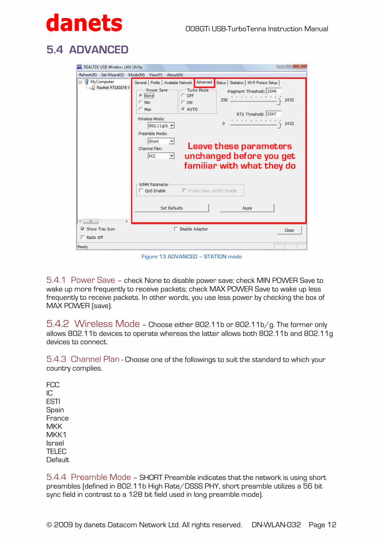
5.4 ADVANCED 5.4.1 Power Save – check None to disable power save; check MIN POWER Save to wake up more frequently to receive packets; check MAX POWER Save to wake up less frequently to receive packets. In other words, you use less power by checking the box of MAX POWER (save).
5.4.2 Wireless Mode – Choose either 802.11b or 802.11b/g. The former only allows 802.11b devices to operate whereas the latter allows both 802.11b and 802.11g devices to connect. 5.4.3 Channel Plan - Choose one of the followings to suit the standard to which your country complies. FCC IC ESTI Spain France MKK MKK1 Israel TELEC Default 5.4.4 Preamble Mode – SHORT Preamble indicates that the network is using short preambles (defined in 802.11b High Rate/DSSS PHY, short preamble utilizes a 56 bit sync field in contrast to a 128 bit field used in long preamble mode).
Figure 13 ADVANCED – STATION mode
008GTi USB-TurboTenna Instruction Manual
© 2009 by danets Datacom Network Ltd. All rights reserved. DN-WLAN-032 Page 13
If your packet error rate is high (over 10%), you are probably experiencing interference. A signal strength indicator may report the signal as "good" with interference. Signal quality may even acceptable, since interference may be intermittent. It is possible for interference to be so bad that you don't see high packet error rates because you don't even recognize incoming packets - this can be verified by comparing the number of packets sent by the AP to the number of packets received by wireless client. Select LONG Preamble with good signal quality, SHORT Preamble for poor signal quality, and AUTO for optimal performance. 5.4.5 Fragment Threshold - Longer data fragment increases data throughput performance with good signal quality. The opposite is true to keep shorter data fragment in poor signal quality to maintain an optimal data throughput. 5.4.6 RTS Threshold – Data packet size which exceeds the Request To Send (RTS) Threshold will be sent out. Larger packet size favors data transmission whilst small pack size lowers the latency for real time traffic (voice and video). 5.4.7 WWM Parameters – WWM stands for Wireless Multi-Media. Check the QUALITY OF SERVICE (QoS) box if you mostly have voice and video real time Multi-Media traffic. Check the POWER SAVE Automatic Power Save Delivery (APSD) ENABLE box for optimal power performance.
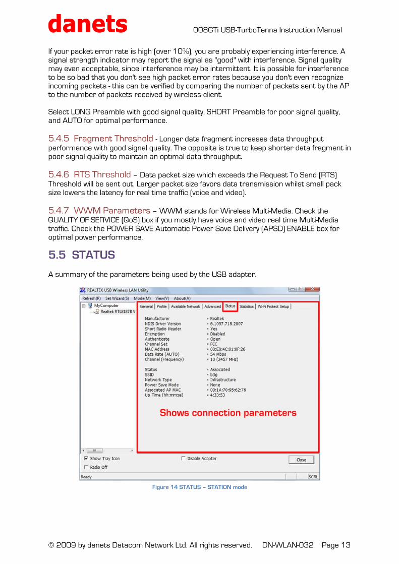
5.5 STATUS A summary of the parameters being used by the USB adapter.
Figure 14 STATUS – STATION mode
008GTi USB-TurboTenna Instruction Manual
© 2009 by danets Datacom Network Ltd. All rights reserved. DN-WLAN-032 Page 14
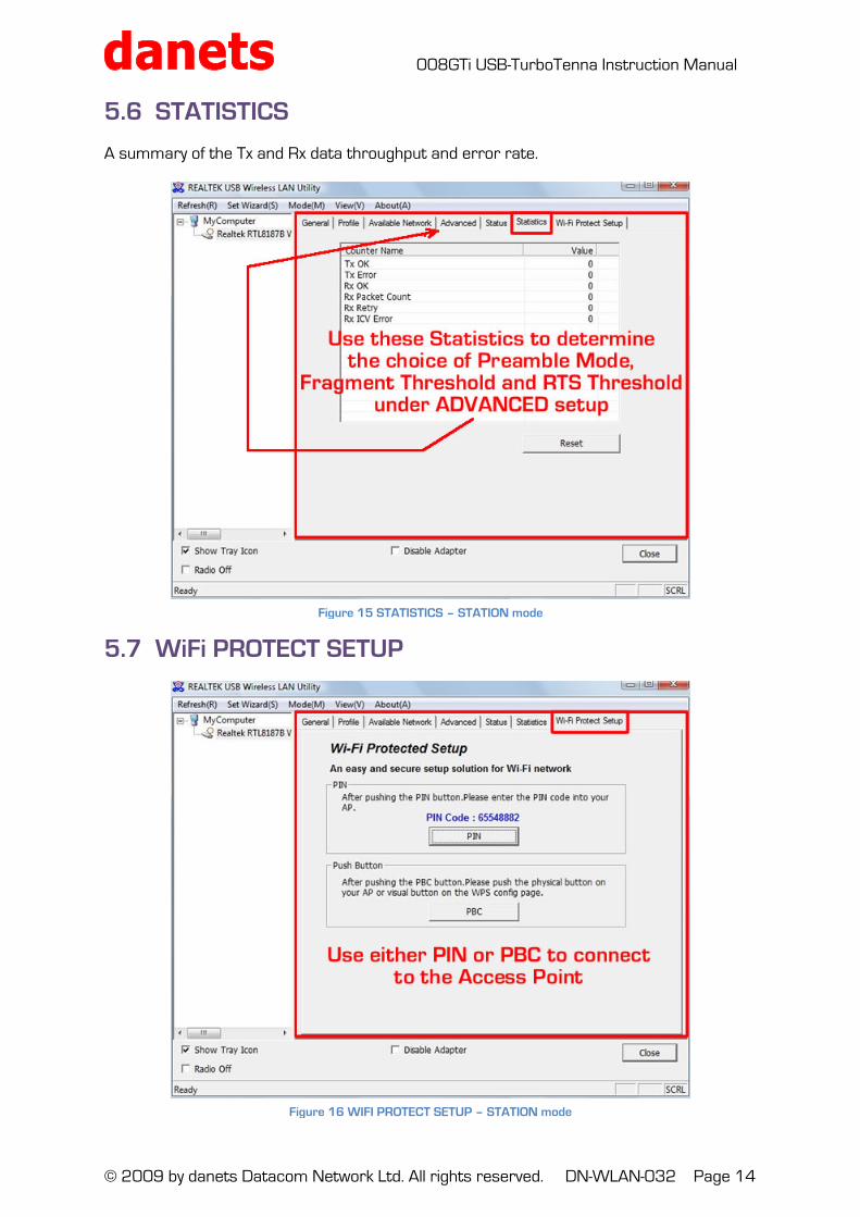
5.6 STATISTICS A summary of the Tx and Rx data throughput and error rate.
5.7 WiFi PROTECT SETUP
Figure 15 STATISTICS – STATION mode
Figure 16 WIFI PROTECT SETUP – STATION mode

008GTi USB-TurboTenna Instruction Manual
© 2009 by danets Datacom Network Ltd. All rights reserved. DN-WLAN-032 Page 15
Wi-Fi Protected Setup (WPS) is a standard for easy and secure establishment of a wireless home network, created by the Wi-Fi Alliance and officially launched on January 8, 2007. The goal of the WPS protocol is to simplify the process of configuring security on wireless networks, and so it was first named 'Wi-Fi Simple Config'. The protocol is meant to allow home users who know little of wireless security and may be intimidated by the available security options to configure Wi-Fi Protected Access, which is supported by all Wi-Fi certified devices. The standard achieves its goal by putting much emphasis into usability and security, and the concept is implemented through four usage models that enable a user to establish a home network. So, to add a new device to the Network the user can have up to the following two choices: PIN Method, in which a PIN (Personal Identification Number) has to be read from either a sticker on the new wireless client device (STA) or a display, if there is one, and entered at the "representant" of the Network, either the wireless access point (AP) or a Registrar of the Network, cf below the Protocol Architecture. This is the mandatory baseline model, every Wi-Fi Protected Setup certified product must support it. PBC Method, in which the user simply has to push a button, either an actual or virtual one, on both the AP (or a Registrar of the Network) and the new wireless client device (STA). Support of this model is mandatory for APs and optional for STAs. This page addresses the common scenario involving an Infrastructure Network. The support of ad hoc networks (IBSS) are not supported by WPS.
008GTi USB-TurboTenna Instruction Manual
© 2009 by danets Datacom Network Ltd. All rights reserved. DN-WLAN-032 Page 16
6. Advanced Setting Options (ACCESS POINT Mode]
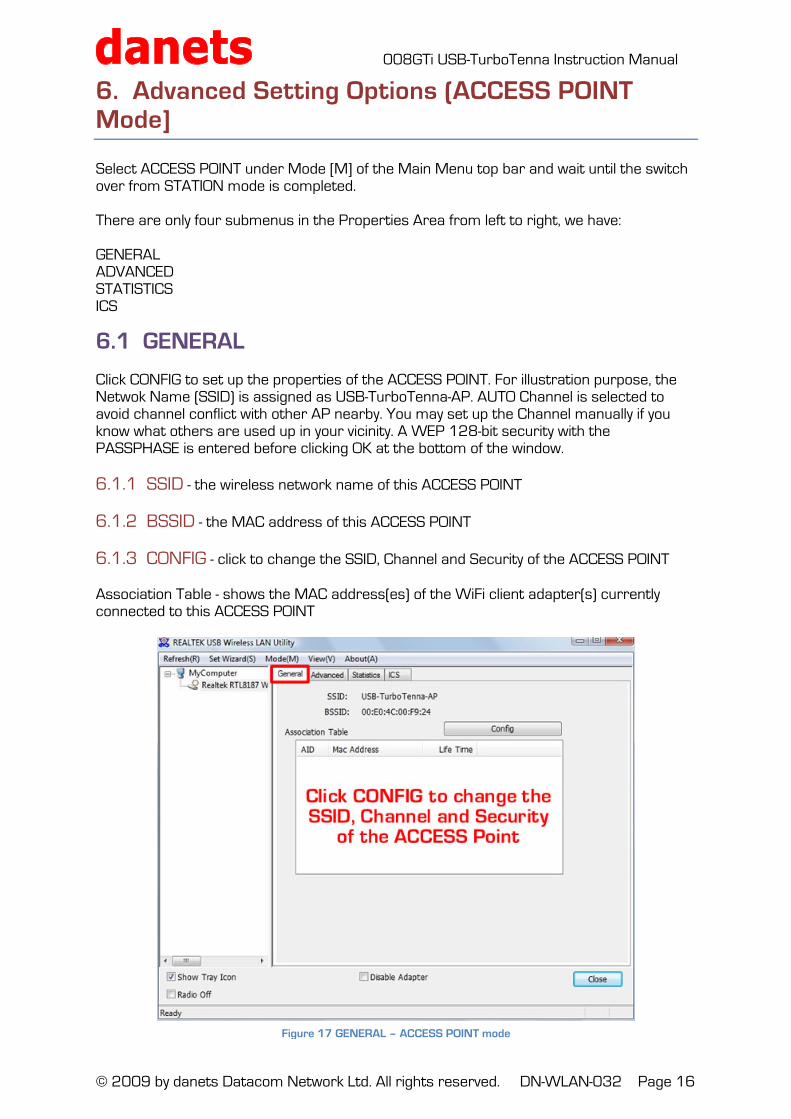
Select ACCESS POINT under Mode [M] of the Main Menu top bar and wait until the switch over from STATION mode is completed. There are only four submenus in the Properties Area from left to right, we have: GENERAL ADVANCED STATISTICS ICS
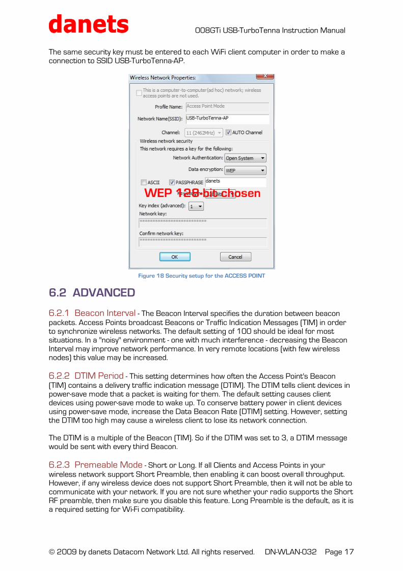
6.1 GENERAL Click CONFIG to set up the properties of the ACCESS POINT. For illustration purpose, the Netwok Name (SSID) is assigned as USB-TurboTenna-AP. AUTO Channel is selected to avoid channel conflict with other AP nearby. You may set up the Channel manually if you know what others are used up in your vicinity. A WEP 128-bit security with the PASSPHASE is entered before clicking OK at the bottom of the window. 6.1.1 SSID - the wireless network name of this ACCESS POINT 6.1.2 BSSID - the MAC address of this ACCESS POINT 6.1.3 CONFIG - click to change the SSID, Channel and Security of the ACCESS POINT Association Table - shows the MAC address(es) of the WiFi client adapter(s) currently connected to this ACCESS POINT
Figure 17 GENERAL – ACCESS POINT mode
008GTi USB-TurboTenna Instruction Manual
© 2009 by danets Datacom Network Ltd. All rights reserved. DN-WLAN-032 Page 17
The same security key must be entered to each WiFi client computer in order to make a connection to SSID USB-TurboTenna-AP.
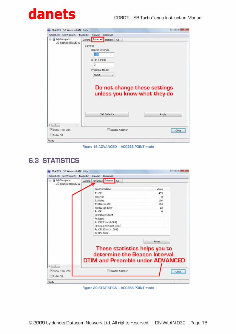
6.2 ADVANCED 6.2.1 Beacon Interval - The Beacon Interval specifies the duration between beacon packets. Access Points broadcast Beacons or Traffic Indication Messages (TIM) in order to synchronize wireless networks. The default setting of 100 should be ideal for most situations. In a "noisy" environment - one with much interference - decreasing the Beacon Interval may improve network performance. In very remote locations (with few wireless nodes) this value may be increased. 6.2.2 DTIM Period - This setting determines how often the Access Point's Beacon (TIM) contains a delivery traffic indication message (DTIM). The DTIM tells client devices in power-save mode that a packet is waiting for them. The default setting causes client devices using power-save mode to wake up. To conserve battery power in client devices using power-save mode, increase the Data Beacon Rate (DTIM) setting. However, setting the DTIM too high may cause a wireless client to lose its network connection. The DTIM is a multiple of the Beacon (TIM). So if the DTIM was set to 3, a DTIM message would be sent with every third Beacon. 6.2.3 Premeable Mode - Short or Long. If all Clients and Access Points in your wireless network support Short Preamble, then enabling it can boost overall throughput. However, if any wireless device does not support Short Preamble, then it will not be able to communicate with your network. If you are not sure whether your radio supports the Short RF preamble, then make sure you disable this feature. Long Preamble is the default, as it is a required setting for Wi-Fi compatibility.
Figure 18 Security setup for the ACCESS POINT
008GTi USB-TurboTenna Instruction Manual
© 2009 by danets Datacom Network Ltd. All rights reserved. DN-WLAN-032 Page 18
6.3 STATISTICS
Figure 19 ADVANCED – ACCESS POINT mode
Figure 20 STATISTICS – ACCESS POINT mode
008GTi USB-TurboTenna Instruction Manual
© 2009 by danets Datacom Network Ltd. All rights reserved. DN-WLAN-032 Page 19
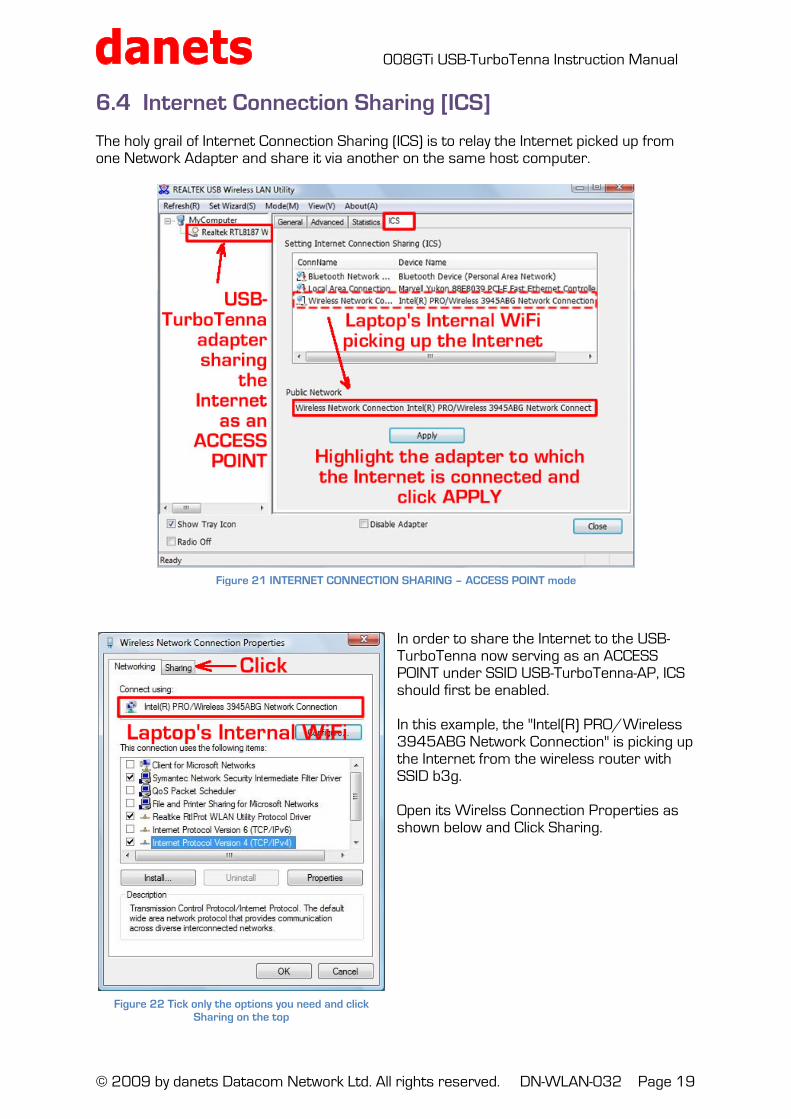
6.4 Internet Connection Sharing [ICS] The holy grail of Internet Connection Sharing (ICS) is to relay the Internet picked up from one Network Adapter and share it via another on the same host computer.
In order to share the Internet to the USB-TurboTenna now serving as an ACCESS POINT under SSID USB-TurboTenna-AP, ICS should first be enabled. In this example, the "Intel(R) PRO/Wireless 3945ABG Network Connection" is picking up the Internet from the wireless router with SSID b3g. Open its Wirelss Connection Properties as shown below and Click Sharing.
Figure 21 INTERNET CONNECTION SHARING – ACCESS POINT mode
Figure 22 Tick only the options you need and click Sharing on the top
008GTi USB-TurboTenna Instruction Manual
© 2009 by danets Datacom Network Ltd. All rights reserved. DN-WLAN-032 Page 20
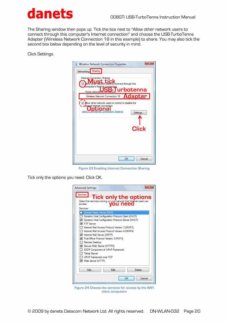
The Sharing window then pops up. Tick the box next to "Allow other network users to connect through this computer's Internet connection" and choose the USB-TurboTenna Adapter (Wireless Network Connection 18 in this example) to share. You may also tick the second box below depending on the level of security in mind. Click Settings. Tick only the options you need. Click OK.
Figure 23 Enabling Internet Connection Sharing
Figure 24 Choose the services for access by the WiFi client computers
008GTi USB-TurboTenna Instruction Manual
© 2009 by danets Datacom Network Ltd. All rights reserved. DN-WLAN-032 Page 21
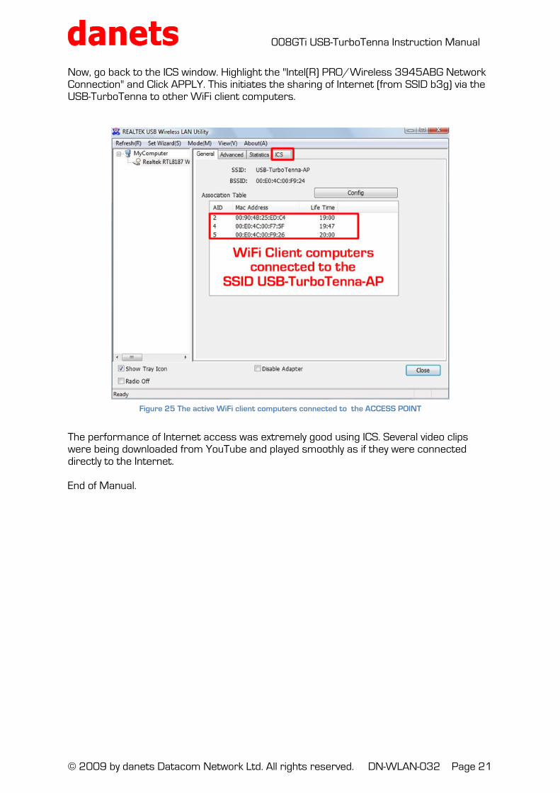
Now, go back to the ICS window. Highlight the "Intel(R) PRO/Wireless 3945ABG Network Connection" and Click APPLY. This initiates the sharing of Internet (from SSID b3g) via the USB-TurboTenna to other WiFi client computers. The performance of Internet access was extremely good using ICS. Several video clips were being downloaded from YouTube and played smoothly as if they were connected directly to the Internet. End of Manual.
Figure 25 The active WiFi client computers connected to the ACCESS POINT


![[About This Software] GNU Lesser General Public License (LGPL) … · 2016-04-10 · GNU Lesser General Public License (LGPL) and other licenses. You may acquire the source code of](https://static.fdocuments.in/doc/165x107/5f94eda14defc11d154cc41e/about-this-software-gnu-lesser-general-public-license-lgpl-2016-04-10-gnu.jpg)