005 sar chap 05 operating systems r4 master€¦ · · 2014-06-27ISF FACILITY Safety Analysis...
108
ISF FACILITY Safety Analysis Report Rev. 4 Page i Contents 5.0 OPERATION SYSTEMS........................................................................................... 5.1-1 5.1 OPERATION DESCRIPTION ..................................................................................... 5.1-1 5.1.1 Narrative Description ........................................................................................ 5.1-2 5.1.1.1 Receipt Operations..................................................................................... 5.1-2 5.1.1.1.1 Acceptance of SNF Shipment ............................................................ 5.1-2 5.1.1.1.2 Receipt of Transfer Cask .................................................................... 5.1-3 5.1.1.1.3 Movement of Transfer Cask into Cask Decontamination Zone ......... 5.1-3 5.1.1.1.4 Movement of the Transfer Cask to FPA............................................. 5.1-3 5.1.1.2 Loading Operations ................................................................................... 5.1-4 5.1.1.2.1 Transfer Cask Lid Removal................................................................ 5.1-4 5.1.1.2.2 Preparations for Performing Fuel Packaging Activities ..................... 5.1-4 5.1.1.2.3 Peach Bottom 1 Fuel Specific Packaging Activities .......................... 5.1-4 5.1.1.2.4 Peach Bottom 2 Fuel Specific Packaging Activities .......................... 5.1-6 5.1.1.2.5 TRIGA Fuel Specific Packaging Activities ....................................... 5.1-7 5.1.1.2.6 Shippingport Fuel Specific Packaging Activities ............................... 5.1-8 5.1.1.2.7 Movement of ISF Canisters/Baskets Between FPA and CCA ........... 5.1-9 5.1.1.2.8 Perform ISF Canister Lid Closure Weld ............................................ 5.1-9 5.1.1.2.9 Canister Vacuum Dry, Inert, and Leak Check ................................. 5.1-10 5.1.1.3 Canister Handling .................................................................................... 5.1-12 5.1.1.3.1 Movement of ISF Canister to SA ..................................................... 5.1-12 5.1.1.3.2 Transfer of ISF Canister from the Canister Trolley to CHM ........... 5.1-12 5.1.1.3.3 Movement of ISF Canister to Storage Tube ..................................... 5.1-13 5.1.1.3.4 Removal of Storage Tube Plug, Placement of ISF Canister in Storage Tube, and Replacement of Storage Tube Plug .................... 5.1-13 5.1.1.3.5 Purge and Inert Storage Tube ........................................................... 5.1-13 5.1.1.4 Storage Operations................................................................................... 5.1-14 5.1.1.5 Ancillary Activities.................................................................................. 5.1-15 5.1.1.5.1 Return Empty Transfer Cask ............................................................ 5.1-15 5.1.1.5.2 Primary Waste Monitoring, Decontamination, Size Reduction in FPA ................................................................................................... 5.1-15 5.1.1.5.3 Receipt and Storage of New ISF Canisters/Baskets ......................... 5.1-16 5.1.1.5.4 Preparation of New ISF Canisters for Fuel Loading ........................ 5.1-17 5.1.1.6 Non-Standard Operations ........................................................................ 5.1-17 5.1.1.6.1 Fuel Handling Machine Recovery .................................................... 5.1-18 5.1.1.6.2 Fuel Packaging Area Shield Doors Recovery .................................. 5.1-18 5.1.1.6.3 Faulty Canister Replacement (Unload) ............................................ 5.1-19 5.1.1.6.4 Faulty Tube Plug Replacement ........................................................ 5.1-19 5.1.1.6.5 Movement of ISF Canister from Storage Tube to New Storage Tube .................................................................................................. 5.1-19 5.1.1.6.6 Worktable Operations - Stuck Fuel Element in Fuel Can, or Can Sleeve Stuck to Fuel Element ........................................................... 5.1-20 5.1.1.6.7 Worktable Operations - Broken Fuel Element in Fuel Can ............. 5.1-20 5.1.1.6.8 Worktable Operations - Broken Fuel Element ................................. 5.1-21 5.1.1.7 Offsite Transportation Operations ........................................................... 5.1-21
Transcript of 005 sar chap 05 operating systems r4 master€¦ · · 2014-06-27ISF FACILITY Safety Analysis...

ISF FACILITY Safety Analysis Report
Rev. 4 Page i
Contents
5.0 OPERATION SYSTEMS........................................................................................... 5.1-1 5.1 OPERATION DESCRIPTION..................................................................................... 5.1-1
5.1.1 Narrative Description........................................................................................ 5.1-2 5.1.1.1 Receipt Operations..................................................................................... 5.1-2
5.1.1.1.1 Acceptance of SNF Shipment ............................................................ 5.1-2 5.1.1.1.2 Receipt of Transfer Cask .................................................................... 5.1-3 5.1.1.1.3 Movement of Transfer Cask into Cask Decontamination Zone......... 5.1-3 5.1.1.1.4 Movement of the Transfer Cask to FPA............................................. 5.1-3
5.1.1.2 Loading Operations ................................................................................... 5.1-4 5.1.1.2.1 Transfer Cask Lid Removal................................................................ 5.1-4 5.1.1.2.2 Preparations for Performing Fuel Packaging Activities..................... 5.1-4 5.1.1.2.3 Peach Bottom 1 Fuel Specific Packaging Activities .......................... 5.1-4 5.1.1.2.4 Peach Bottom 2 Fuel Specific Packaging Activities .......................... 5.1-6 5.1.1.2.5 TRIGA Fuel Specific Packaging Activities ....................................... 5.1-7 5.1.1.2.6 Shippingport Fuel Specific Packaging Activities............................... 5.1-8 5.1.1.2.7 Movement of ISF Canisters/Baskets Between FPA and CCA........... 5.1-9 5.1.1.2.8 Perform ISF Canister Lid Closure Weld ............................................ 5.1-9 5.1.1.2.9 Canister Vacuum Dry, Inert, and Leak Check ................................. 5.1-10
5.1.1.3 Canister Handling .................................................................................... 5.1-12 5.1.1.3.1 Movement of ISF Canister to SA ..................................................... 5.1-12 5.1.1.3.2 Transfer of ISF Canister from the Canister Trolley to CHM ........... 5.1-12 5.1.1.3.3 Movement of ISF Canister to Storage Tube..................................... 5.1-13 5.1.1.3.4 Removal of Storage Tube Plug, Placement of ISF Canister in
Storage Tube, and Replacement of Storage Tube Plug.................... 5.1-13 5.1.1.3.5 Purge and Inert Storage Tube ........................................................... 5.1-13
5.1.1.4 Storage Operations................................................................................... 5.1-14 5.1.1.5 Ancillary Activities.................................................................................. 5.1-15
5.1.1.5.1 Return Empty Transfer Cask ............................................................ 5.1-15 5.1.1.5.2 Primary Waste Monitoring, Decontamination, Size Reduction in
FPA................................................................................................... 5.1-15 5.1.1.5.3 Receipt and Storage of New ISF Canisters/Baskets......................... 5.1-16 5.1.1.5.4 Preparation of New ISF Canisters for Fuel Loading ........................ 5.1-17
5.1.1.6 Non-Standard Operations ........................................................................ 5.1-17 5.1.1.6.1 Fuel Handling Machine Recovery.................................................... 5.1-18 5.1.1.6.2 Fuel Packaging Area Shield Doors Recovery .................................. 5.1-18 5.1.1.6.3 Faulty Canister Replacement (Unload) ............................................ 5.1-19 5.1.1.6.4 Faulty Tube Plug Replacement ........................................................ 5.1-19 5.1.1.6.5 Movement of ISF Canister from Storage Tube to New Storage
Tube.................................................................................................. 5.1-19 5.1.1.6.6 Worktable Operations - Stuck Fuel Element in Fuel Can, or Can
Sleeve Stuck to Fuel Element........................................................... 5.1-20 5.1.1.6.7 Worktable Operations - Broken Fuel Element in Fuel Can ............. 5.1-20 5.1.1.6.8 Worktable Operations - Broken Fuel Element ................................. 5.1-21
5.1.1.7 Offsite Transportation Operations ........................................................... 5.1-21

ISF FACILITY Safety Analysis Report
Rev. 4 Page ii
5.1.2 Flowsheets....................................................................................................... 5.1-22 5.1.3 Identification of Subjects for Safety Analysis ................................................ 5.1-22
5.1.3.1 Criticality Prevention............................................................................... 5.1-22 5.1.3.1.1 Fuel in Transfer Cask ....................................................................... 5.1-24 5.1.3.1.2 Fuel in Fuel Packaging Area ............................................................ 5.1-24 5.1.3.1.3 Waste from Fuel Elements in the Fuel Packaging Area................... 5.1-26 5.1.3.1.4 Fuel in ISF Canister.......................................................................... 5.1-27 5.1.3.1.5 Loaded ISF Canister in Storage Tube and Storage Vault................. 5.1-28
5.1.3.2 Chemical Safety....................................................................................... 5.1-28 5.1.3.3 Operation Shutdown Modes .................................................................... 5.1-28
5.1.3.3.1 Shutdown of Receipt Operations...................................................... 5.1-29 5.1.3.3.2 Shutdown of Loading Operations..................................................... 5.1-30 5.1.3.3.3 Shutdown of Canister Handling ....................................................... 5.1-31 5.1.3.3.4 Shutdown of Storage Operations...................................................... 5.1-31
5.1.3.4 Instrumentation ........................................................................................ 5.1-32 5.1.3.5 Maintenance Techniques ......................................................................... 5.1-32
5.1.3.5.1 Transfer Cask.................................................................................... 5.1-33 5.1.3.5.2 Cask Receipt Crane .......................................................................... 5.1-33 5.1.3.5.3 Cask Trolley ..................................................................................... 5.1-33 5.1.3.5.4 Transfer Tunnel Doors ..................................................................... 5.1-34 5.1.3.5.5 Fuel Handling Machine .................................................................... 5.1-34 5.1.3.5.6 Decanning Machine.......................................................................... 5.1-34 5.1.3.5.7 ISF Canisters and ISF Baskets ......................................................... 5.1-35 5.1.3.5.8 Master/Slave Manipulators............................................................... 5.1-35 5.1.3.5.9 Worktable ......................................................................................... 5.1-35 5.1.3.5.10 Canister Trolley ................................................................................ 5.1-35 5.1.3.5.11 Bench Containment Vessels ............................................................. 5.1-36 5.1.3.5.12 Canister Closure Area Crane ............................................................ 5.1-36 5.1.3.5.13 ISF Canister Welding System .......................................................... 5.1-36 5.1.3.5.14 Vacuum Dry, Helium Fill, and Leak Check System........................ 5.1-36 5.1.3.5.15 Canister Handling Machine.............................................................. 5.1-36 5.1.3.5.16 Storage Tubes ................................................................................... 5.1-36 5.1.3.5.17 Radiation Monitoring Systems ......................................................... 5.1-37 5.1.3.5.18 Process Monitoring Instrumentation ................................................ 5.1-37 5.1.3.5.19 Closed Circuit Television Monitoring Systems ............................... 5.1-37 5.1.3.5.20 Shield Window ................................................................................. 5.1-37 5.1.3.5.21 Fire Protection System ..................................................................... 5.1-37
5.2 SPENT FUEL HANDLING SYSTEMS ...................................................................... 5.2-1 5.2.1 Spent Fuel Receipt, Handling, and Transfer..................................................... 5.2-1
5.2.1.1 Functional Description............................................................................... 5.2-1 5.2.1.1.1 Transfer Cask...................................................................................... 5.2-1 5.2.1.1.2 Cask Receipt Crane ............................................................................ 5.2-1 5.2.1.1.3 Cask Trolley ....................................................................................... 5.2-2 5.2.1.1.4 Transfer Tunnel Doors ....................................................................... 5.2-2 5.2.1.1.5 Fuel Handling Machine ...................................................................... 5.2-2 5.2.1.1.6 Decanning Machine............................................................................ 5.2-3
ISF FACILITY Safety Analysis Report
Rev. 4 Page iii
5.2.1.1.7 ISF Canisters and ISF Baskets ........................................................... 5.2-3 5.2.1.1.8 Master/Slave Manipulator .................................................................. 5.2-3 5.2.1.1.9 Worktable ........................................................................................... 5.2-4 5.2.1.1.10 Canister Trolley .................................................................................. 5.2-4 5.2.1.1.11 Bench Containment Vessels ............................................................... 5.2-5 5.2.1.1.12 ISF Canister Welding System ............................................................ 5.2-5 5.2.1.1.13 Vacuum Dry, Helium Fill, and Leak Check System.......................... 5.2-5
5.2.1.2 Safety Features........................................................................................... 5.2-6 5.2.1.2.1 Transfer Cask...................................................................................... 5.2-7 5.2.1.2.2 Cask Receipt Crane ............................................................................ 5.2-7 5.2.1.2.3 Cask Trolley ....................................................................................... 5.2-8 5.2.1.2.4 Transfer Tunnel Doors ....................................................................... 5.2-9 5.2.1.2.5 Fuel Handling Machine ...................................................................... 5.2-9 5.2.1.2.6 Decanning Machine.......................................................................... 5.2-10 5.2.1.2.7 ISF Canisters and ISF Baskets ......................................................... 5.2-10 5.2.1.2.8 Master/Slave Manipulators............................................................... 5.2-10 5.2.1.2.9 Worktable ......................................................................................... 5.2-11 5.2.1.2.10 Canister Trolley ................................................................................ 5.2-12 5.2.1.2.11 Bench Containment Vessels ............................................................. 5.2-12 5.2.1.2.12 ISF Canister Welding System .......................................................... 5.2-13 5.2.1.2.13 Vacuum Dry, Helium Fill, and Leak Check System........................ 5.2-13
5.2.2 Spent Fuel Storage .......................................................................................... 5.2-13 5.2.2.1 Safety Features......................................................................................... 5.2-15
5.2.2.1.1 Canister Handling Machine.............................................................. 5.2-15 5.2.2.1.2 Storage Tube Assemblies and Storage Vault ................................... 5.2-17
5.2.2.2 Maintenance............................................................................................. 5.2-17 5.2.2.2.1 Canister Handling Machine.............................................................. 5.2-17 5.2.2.2.2 Storage Tube Modules and Vault ..................................................... 5.2-17
5.3 OTHER OPERATING SYSTEMS............................................................................... 5.3-1 5.3.1 Operating Systems ............................................................................................ 5.3-1
5.3.1.1 HVAC System ........................................................................................... 5.3-1 5.3.1.1.1 Functional Description – Transfer Area HVAC................................. 5.3-1 5.3.1.1.2 Major Components – Transfer Area HVAC ...................................... 5.3-2 5.3.1.1.3 Design Description – Transfer Area HVAC ...................................... 5.3-2 5.3.1.1.4 Safety Criteria and Assurance – Transfer Area HVAC...................... 5.3-2 5.3.1.1.5 Operating Limits – Transfer Area HVAC .......................................... 5.3-2
5.3.1.2 Electrical Power Distribution .................................................................... 5.3-2 5.3.1.2.1 Functional Description ....................................................................... 5.3-2 5.3.1.2.2 Major Components ............................................................................. 5.3-3 5.3.1.2.3 Design Description ............................................................................. 5.3-3 5.3.1.2.4 Safety Criteria and Assurance ............................................................ 5.3-3 5.3.1.2.5 Operating Limits................................................................................. 5.3-3
5.3.1.3 Integrated Data Collection System (IDCS) ............................................... 5.3-3 5.3.1.4 Liquid Waste Processing System............................................................... 5.3-3 5.3.1.5 Solid Waste Processing System................................................................. 5.3-3 5.3.1.6 Radiation Monitoring System.................................................................... 5.3-3

ISF FACILITY Safety Analysis Report
Rev. 4 Page iv
5.3.1.7 Fire Protection/Communication System.................................................... 5.3-4 5.3.1.8 Compressed Air System ............................................................................ 5.3-4 5.3.1.9 Breathing Air System ................................................................................ 5.3-4 5.3.1.10 Potable Water Supply System ................................................................... 5.3-4 5.3.1.11 Sewage Treatment System......................................................................... 5.3-4
5.3.2 Component/Equipment Spares.......................................................................... 5.3-4 5.4 OPERATION SUPPORT SYSTEMS .......................................................................... 5.4-1
5.4.1 Instrumentation and Control Systems............................................................... 5.4-1 5.4.1.1 Functional Description............................................................................... 5.4-1 5.4.1.2 Major Components .................................................................................... 5.4-2 5.4.1.3 Detection System and Location ................................................................. 5.4-3 5.4.1.4 Functions of ITS Systems and Equipment Instrumentation and Controls. 5.4-3 5.4.1.5 Safety Criteria and Assurance ................................................................... 5.4-3 5.4.1.6 Operating Characteristics........................................................................... 5.4-3
5.4.2 System and Component Spares......................................................................... 5.4-3 5.5 CONTROL ROOM AND CONTROL AREAS........................................................... 5.5-1 5.6 ANALYTICAL SAMPLING ....................................................................................... 5.6-1 5.7 REFERENCES ............................................................................................................. 5.7-1
Tables
Table 5.1-1 Summary of Criticality Prevention Table 5.1-2 Bounding Criticality Evaluations Table 5.4-1 Major Component Interlocks and Functions Classified ITS
Figures
Figure 5.1-1 General Arrangement of Areas Figure 5.1-2 Remove Transfer Cask from Transporter Figure 5.1-3 Move Transfer Cask to Cask Trolley Figure 5.1-4 Moving SNF to FPA and Return Transfer Cask Figure 5.1-5 Fuel Packaging Area Configuration Peach Bottom 1 Fuel Figure 5.1-6 Fuel Packaging Area Bench Configuration Peach Bottom 1 Fuel Figure 5.1-7 Fuel Packaging Area Configuration Peach Bottom 2 Fuel Figure 5.1-8 Fuel Packaging Area Bench Configuration Peach Bottom 2 Fuel Figure 5.1-9 Fuel Packaging Area Configuration TRIGA Fuel Figure 5.1-10 Fuel Packaging Area Bench Configuration TRIGA Fuel Figure 5.1-11 Fuel Packaging Area Configuration Shippingport Fuel Figure 5.1-12 Fuel Packaging Area Bench Configuration Shippingport Fuel Figure 5.1-13 Canister Welding, Vacuum Dry, Helium Fill and Leak Check Layout Figure 5.1-14 ISF Canister Lid Closure Weld Figure 5.1-15 Vacuum Dry, Inert and Leak Check
ISF FACILITY Safety Analysis Report
Rev. 4 Page v
Figure 5.1-16 Helium Charging Tool Figure 5.1-17 Receipt and Storage of New ISF Canister Figure 5.1-18 Figure Not Used Figure 5.1-19 Placement of New ISF Canister into Canister Cask Figure 5.1-20 Preparation of Canister for Fuel Loading Figure 5.1-21 Worktable Facilities Stuck Fuel Element or Can Sleeve Stuck to Element Figure 5.1-22 Cask Receipt and Return Figure 5.1-23 Peach Bottom 1 Fuel Figure 5.1-24 Peach Bottom 2 Fuel Figure 5.1-25 TRIGA Fuel Figure 5.1-26 Shippingport Fuel Figure 5.1-27 Canister Closure Area Figure 5.1-28 Dry Store CHM Operation Sequence

ISF FACILITY Safety Analysis Report
Rev. 4 Page vi
THIS PAGE INTENTIONALLY LEFT BLANK.
ISF FACILITY Safety Analysis Report
Rev. 4 Page 5.1-1
5.0 OPERATION SYSTEMS
This chapter summarizes the Idaho Spent Fuel (ISF) Facility operations. Section 5.1 provides a summary of the operations associated with the receipt, handling, and storage of the spent nuclear fuel (SNF) at the ISF Facility. The systems directly relied on to perform these operations are described in Section 5.2. Other operating systems for the remainder of the facility are discussed in Section 5.3. Instrumentation and control features associated with operation control, monitors, and alarms are summarized in Section 5.4. Section 5.5 discusses how control areas are designed to permit occupancy, and the actions to be taken to operate the installation safely under normal and off-normal conditions. Section 5.6 discusses the analytical sampling methods available to verify that facility operation is in accordance with design. The operation systems provide safe control of fuel handling and storage systems, in accordance with 10 Code of Federal Regulations (CFR) 72.122(j) (Ref. 5-1).
Fuel receipt, handling, and storage at the ISF Facility are subject to the requirements of the ISF license issued in accordance with 10 CFR 72.
5.1 OPERATION DESCRIPTION
This section provides an overview of operations associated with the receipt, handling, and storage of the SNF at the ISF Facility. Figure 5.1-1 illustrates the general arrangement of the ISF facility areas and equipment. Figures are provided to facilitate understanding of the process. Facility activities involving SNF fall into one of four “modes” defined in the Technical Specifications (TS): receipt operations, loading operations, canister handling, and storage operations.
Receipt operations begin when the SNF is received at the ISF Facility and include movement of the Transfer Cask into the Cask Receipt Area; offloading the cask onto the cask trolley, installation of the cask adapter remote release lid restraint, moving the cask through the outer tunnel door into the Cask Decontamination Zone, venting and sampling the Transfer Cask atmosphere, and removal of the Transfer Cask lid bolts. The Transfer Cask is then moved below the FPA cask port and the cask port inflatable seal is inflated. Receipt operations end, and loading operations begin, when the cask adapter’s first remote release lid restrain is disengaged.
Loading operations begin when the first remote lid restraint of the cask adapter is disengaged. Loading activities include activities to remove, inventory, inspect, and repackage the fuel into ISF baskets; transferring the loaded ISF basket into the ISF canister in the canister trolley; and moving the loaded ISF canister to the Canister Closure Area (CCA). Loading operations continue in the CCA with the welding of the ISF canister lid, non-destructive examination (NDE) of the weld, vacuum drying and inerting the ISF canister, and leak rate testing. Loading operations end and canister handling begins after the ISF canister has met TS limits.
Canister handling includes moving the sealed ISF canister through the Transfer Tunnel to the Storage Area; transferring of the canister from the canister trolley to the canister handling machine (CHM); placing the ISF canister into the storage tubes; closing, and inerting the storage tubes; and leak rate testing. Canister handling ends, and storage operations begin, when the storage tube has met TS limits.
Storage operations include the periodic surveillances required by TS. The facility license does not contain provisions for transfer of fuel offsite or termination of storage operations.

ISF FACILITY Safety Analysis Report
Rev. 4 Page 5.1-2
At any one time, ISF operations can involve any combination of the four TS-defined modes. A more detailed description of the activities associated with each of these four modes is provided in Section 5.1.1.
The ISF Facility functions to confine the radioactive material and prevent the release of radioactive particulate to the environment above radiological limits prescribed in Chapter 7. Radioactive material at the ISF Facility is confined by physical barriers and ventilation system design features. Physical barriers such as containers (e.g., canisters and casks), pipes, walls, floors, ceilings, windows, doors, and seals prevent the spread of radioactive material. In addition, the ventilation system ensures that air flows from areas of low potential contamination to areas of higher potential contamination and finally to areas of likely contamination. Chapter 4 provides additional information on confinement boundaries. For the SNF, the ISF canister provides the first level of confinement and the storage tube provides the second level of confinement during storage.
5.1.1 Narrative Description
SNF receipt, loading, handling, and storage operations at the ISF Facility are described in this section based on the four operational modes outlined in Section 5.1. Flowsheets showing major activities are provided as Figures 5.1-22 through 5.1-28.
5.1.1.1 Receipt Operations
This section describes the methods and general sequence for the following receipt operations:
• acceptance of SNF shipment
• receipt of Transfer Cask
• movement of Transfer Cask into Cask Decontamination Zone
• movement of Transfer Cask to FPA
The following sub-sections provide an overview of the operations listed above. The process is illustrated in Figure 5.1-2 and Figure 5.1-3.
5.1.1.1.1 Acceptance of SNF Shipment
Before a shipment of SNF is accepted, shipping papers are reviewed to verify that: (1) the Transfer Cask contains only one type of SNF (i.e., Peach Bottom, TRIGA, or Shippingport), and (2) the SNF to be received is of the same type as may be present in the FPA. This shipping paper review ensures that only one type of SNF will be present in the FPA at any one time, to meet TS SNF limits and fuel handling program limits. Before accepting the first shipment of a given type of SNF, the review also ensures the FPA has been configured to handle the type of SNF to be received.
Security inspections are conducted before allowing the Transfer Cask and transporter on site. Radiological receipt surveys may either be conducted prior to site entry or after arrival in the Cask Receipt Area. When the inspection and survey activities are complete, the SNF shipment is accepted, and the Transfer Cask is moved to the Cask Receipt Area.

ISF FACILITY Safety Analysis Report
Rev. 4 Page 5.1-3
5.1.1.1.2 Receipt of Transfer Cask
The transporter is backed into the Cask Receipt Area. With the Transfer Cask positioned under the cask receipt auxiliary crane, the Transfer Cask restraints and impact limiters (if used) are removed. Next, the Transfer Cask is secured to the cask receipt crane and the cask receipt crane is used to upend and lift the Transfer Cask clear of the transporter, and the transporter is removed from the Cask Receipt Area to allow access for the cask trolley. The maximum lift height will be administratively controlled to ensure the cask is lifted only high enough to safely clear the transporter and cask trolley.
The cask trolley is positioned under the Transfer Cask, and the Transfer Cask is lowered into it. The cask restraint is secured and the cask receipt crane is detached from the load.
The cask receipt auxiliary crane is used to attach the cask adapter (that incorporates remote-release lid restraints, hold-down features, and a sealing surface for the cask trolley inflatable seal) to the Transfer Cask. The remote-release lid restraints hold the Transfer Cask lid in position after it is unbolted and facilitate removal of the lid with the fuel handling machine (FHM) in the FPA. The hold-down features secure the Transfer Cask to the cask trolley. The cask adapter sealing surface mates with the cask port inflatable seal and establishes a confinement boundary when the SNF is transferred into the FPA.
Next, the cask lid lifting attachment is secured to the Transfer Cask for subsequent removal of the Transfer Cask lid using the FHM. The cask lid lifting attachment is classified ITS since it is part of the load path for lifting the Transfer Cask lid.
5.1.1.1.3 Movement of Transfer Cask into Cask Decontamination Zone
Since the cask trolley and canister trolley run on common rails, the canister trolley position is verified before moving the cask trolley to the Cask Decontamination Zone.
Operations will verify that the inner tunnel door is closed and Health Physics will verify the radiological conditions to allow opening of the outer tunnel door. HVAC will be shifted to allow for equilization of pressure and the outer tunnel door is then opened. The cask trolley is moved to the Cask Decontamination Zone, the outer tunnel door is closed and HVAC restored to normal differential pressure requirements. The ventilation system must be operating properly before the Transfer Cask atmosphere is vented, monitored, and sampled and the Transfer Cask lid bolts are removed. This ensures that potential airborne contaminants are confined, personnel are protected against radiation, and TS requirements are met before loading operations begin. With the cask in the Cask Decontamination Zone the cask atmosphere is sampled and checked against cask acceptance criteria (50 percent of the lower explosive limit) for the presence of flammable gases (flammable atmosphere). If acceptable, the cask lid bolts are removed in preparation for unloading the fuel in the FPA. If explosive gas concentrations are above the acceptance criteria, purging of the cask interior will continue until the acceptance criteria is met.
5.1.1.1.4 Movement of the Transfer Cask to FPA
Figure 5.1-4 shows the operations for moving the SNF to the FPA. After the Transfer Cask lid bolts are unbolted and removed, the inner tunnel door is opened, the cask trolley is moved into the transfer tunnel, and the inner tunnel door is closed. The cask trolley is positioned under the FPA cask port, and the cask trolley seismic locking pin is engaged to ensure seismic stability during subsequent SNF transfer.

ISF FACILITY Safety Analysis Report
Rev. 4 Page 5.1-4
The cask port inflatable seal is then inflated to include the Transfer Cask as part of the FPA confinement boundary. With the cask port seal verified inflated, the FHM is used to remove the cask port plug.
The power manipulator system (PMS) is used to release the Transfer Cask remote release lid restraints so the FHM hoist can remove the Transfer Cask lid. Receipt operations end when the first remote lid restraint of the cask adapter is disengaged and loading operations begin.
5.1.1.2 Loading Operations
This section provides the methods and general sequence for the following loading operations:
• removal of Transfer Cask lid
• preparations for performing fuel packaging activities
• fuel-specific packaging activities for each type of SNF
• movement of ISF canisters/baskets between FPA and CCA
• ISF canister lid closure weld
• ISF canister vacuum dry, inert, and leak check
5.1.1.2.1 Transfer Cask Lid Removal
Loading operations begin when the first remote release lid restraint of the cask adapter is disengaged. The remaining three lid restraints are disengaged to allow removal of the Transfer Cask lid. The FHM hoist is used to remove the Transfer Cask lid. As discussed in Section 5.1.1.2.2 below, the FPA has already been prepared for the specific fuel type to be repackaged. Sections 5.1.1.2.3 through 5.1.1.2.9 discuss the remaining activities performed during loading operations.
5.1.1.2.2 Preparations for Performing Fuel Packaging Activities
Before performing SNF fuel packaging activities for any type of SNF, the FPA is configured to receive, handle, and temporarily store that type of fuel. FPA configuration activities include installing bench containment vessel (BCV) adapter sleeves and inserts, placing covers over unused BCVs, prestaging appropriate ISF baskets in fuel loading stations, and staging appropriate lifting devices and ancillary equipment that will be required for the type of SNF. The proper FPA configuration is verified before receiving SNF, in accordance with TS Fuel Handling Program requirements.
Figures 5.1-5 through 5.1-12 provide plan and cross-sectional views of the FPA arrangement for the respective fuel types.
5.1.1.2.3 Peach Bottom 1 Fuel Specific Packaging Activities
Background Information
The Peach Bottom 1 fuel elements are contained in fuel cans. Although all Peach Bottom 1 fuel is canned, the elements are contained in one of four different container arrangements:
• Peach Bottom 1 intact fuel elements in aluminum cans
• Peach Bottom 1 failed fuel elements with attached removal tools in aluminum cans

ISF FACILITY Safety Analysis Report
Rev. 4 Page 5.1-5
• Peach Bottom 1 failed fuel elements with attached removal tools in aluminum cans overpacked into aluminum salvage cans
• Peach Bottom 1 partial fuel elements in stainless steel overpacks
These fuel cans, in turn, are contained in aluminum or stainless steel fuel baskets. Once the fuel cans and overpacks are removed, some of the fuel baskets will be returned in the Transfer Cask for future use. The fuel cans, salvage cans, and overpacks will not be returned for reuse, but will be processed as radioactive solid waste.
An ISF canister will contain ten intact fuel elements or seven failed fuel elements.
Normal Operations
Before initiating packaging activities associated with the Peach Bottom 1 fuel, the appropriate FPA configuration (Figure 5.1-5 and Figure 5.1-6) is established, and a DOE fuel basket containing Peach Bottom 1 fuel has been placed in the fuel basket operations and monitoring station.
If present, the DOE fuel basket lid is unbolted, removed, and placed in the DOE fuel basket lid park station. Using the FHM, a fuel can is removed from the fuel basket, checked against the manifest and placed in the decanning machine. If the fuel can is a salvage can, two cutting operations are conducted. The first cut removes the salvage can lid and expose the inner fuel can. The second removes the inner fuel can lid and exposes the top of the fuel element. If the fuel can is not a salvage can, only the second cut is required.
Once the fuel can lid(s) is (are) removed, the FHM is used to lift the intact fuel element (or damaged fuel element with attached lifting tool) from the can for inspection and recording of fuel element identification information.
• If the fuel element is broken (as evidenced by visual inspection or FHM load cell underweight), it is reinserted into the fuel can and the fuel can is transferred to the worktable. Handling of broken fuel elements is addressed in Section 5.1.1.6.7, Worktable Operations – Broken Fuel Element in Fuel Can.
• If the fuel element is stuck in the can (as evidenced by FHM load cell overweight), or the can sleeve is stuck to the fuel element, the fuel can is also transferred to the worktable. Packaging of these fuel elements is addressed in Section 5.1.1.6.6, Worktable Operations – Stuck Fuel Element in Fuel Can, or Can Sleeve Stuck to Fuel Element.
• If the fuel element is intact, it is loaded into the ISF fuel basket in a fuel loading station (e.g., Station 1 or 2) configured to receive intact fuel. If the fuel element is a damaged element with attached removal tool, it is loaded into the ISF attached removal tool (ART) basket. The empty fuel can or salvage can is removed from the decanning machine and placed in the designated waste station.

ISF FACILITY Safety Analysis Report
Rev. 4 Page 5.1-6
This process is repeated until the ISF baskets or the designated waste stations are full, or the DOE fuel basket is empty.
• If the DOE fuel basket is empty, the fuel basket lid and bolts are replaced and the empty fuel basket is moved to the designated waste station (for return). Another DOE fuel basket is received and placed in the fuel basket operations and monitoring station, the empty DOE fuel basket is moved to the Transfer Cask for return (if required), and loading operations are resumed.
• If the ISF fuel basket or ISF ART basket is full, the full ISF basket is placed in the ISF canister and moved to the CCA for welding, vacuum drying, inerting, and leak checking operations. Before moving the ISF basket from the fuel loading station, the basket lid is replaced and locked in place. The locking lid secures the fuel in the ISF basket and supports the ISF canister shield plug.
• If the designated waste stations are full, preparations are made to monitor, decontaminate, or section the waste before transfer from the FPA to the Solid Waste Processing Area (SWPA). Waste monitoring and decontamination operations conducted in the FPA are discussed in Section 5.1.1.5.2, Primary Waste Monitoring, Decontamination, Size Reduction in FPA.
5.1.1.2.4 Peach Bottom 2 Fuel Specific Packaging Activities
Background Information
The Peach Bottom 2 fuel elements have 18 inches of the top reflector and the fuel element lifting fixture removed. A grid was used by DOE during the initial loading of the Peach Bottom 2 fuel elements. Once loaded, the grid was removed, leaving the fuel elements free to move within the canister. The DOE canister containing the loose fuel elements will not ordinarily be returned, but will be processed as radioactive solid waste. Use of the decanning machine is not required for Peach Bottom 2 fuel, as the fuel elements are not contained in individual fuel cans. An ISF canister will contain ten intact elements or seven failed fuel elements.
Normal Operations
Before packaging activities begin for the Peach Bottom 2 fuel, the appropriate FPA configuration (Figure 5.1-7 and Figure 5.1-8) is established, and a DOE fuel canister containing Peach Bottom 2 fuel has been placed in the fuel basket operations and monitoring station.
The DOE fuel canister lid plunger clamps are released, and the fuel canister lid is removed and placed in the DOE fuel basket lid park station. The master/slave manipulators (MSMs) or PMS are used to isolate one fuel element so the FHM can grapple and lift the isolated fuel element from the canister. The fuel element is visually inspected and pertinent fuel identification information is recorded.
• If the fuel element is not broken, it is loaded into the ISF fuel basket in the fuel loading station.
• If the fuel element is broken (as evidenced by visual inspection or FHM load cell underweight), it is moved to the worktable. Packaging of broken fuel elements is addressed in Section 5.1.1.6.8, Worktable Operations – Broken Fuel Element.
This process is repeated until the ISF fuel baskets are full, or the designated waste stations are full, or the DOE fuel canister is empty.
ISF FACILITY Safety Analysis Report
Rev. 4 Page 5.1-7
• If the ISF basket is full, the full ISF basket is placed in the ISF canister and moved to the CCA for welding, vacuum drying, inerting, and leak checking operations. Before the ISF basket is moved from the fuel loading station, the basket lid is replaced and locked in place.
• If the DOE fuel canister is empty, preparations are made to monitor, decontaminate, or section the canister before transfer from the FPA to the SWPA. Waste monitoring and decontamination operations conducted in the FPA are discussed in Section 5.1.1.5.2, Primary Waste Monitoring, Decontamination, Size Reduction in FPA.
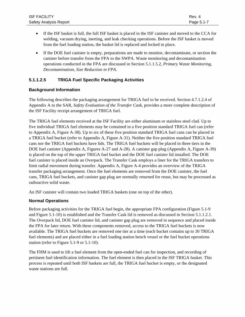
5.1.1.2.5 TRIGA Fuel Specific Packaging Activities
Background Information
The following describes the packaging arrangement for TRIGA fuel to be received. Section 4.7.1.2.4 of Appendix A to the SAR, Safety Evaluation of the Transfer Cask, provides a more complete description of the ISF Facility receipt arrangement of TRIGA fuel.
The TRIGA fuel elements received at the ISF Facility are either aluminum or stainless steel clad. Up to five individual TRIGA fuel elements may be contained in a five position standard TRIGA fuel can (refer to Appendix A, Figure A-38). Up to six of these five position standard TRIGA fuel cans can be placed in a TRIGA fuel bucket (refer to Appendix A, Figure A-31). Neither the five position standard TRIGA fuel cans nor the TRIGA fuel buckets have lids. The TRIGA fuel buckets will be placed in three tiers in the DOE fuel canister (Appendix A, Figures A-27 and A-28). A canister gap plug (Appendix A, Figure A-39) is placed on the top of the upper TRIGA fuel bucket and the DOE fuel canister lid installed. The DOE fuel canister is placed inside an Overpack. The Transfer Cask employs a liner for the TRIGA transfers to limit radial movement during transfer. Appendix A, Figure A-4 provides an overview of the TRIGA transfer packaging arrangement. Once the fuel elements are removed from the DOE canister, the fuel cans, TRIGA fuel buckets, and canister gap plug are normally returned for reuse, but may be processed as radioactive solid waste.
An ISF canister will contain two loaded TRIGA baskets (one on top of the other).
Normal Operations
Before packaging activities for the TRIGA fuel begin, the appropriate FPA configuration (Figure 5.1-9 and Figure 5.1-10) is established and the Transfer Cask lid is removed as discussed in Section 5.1.1.2.1. The Overpack lid, DOE fuel canister lid, and canister gap plug are removed in sequence and placed inside the FPA for later return. With these components removed, access to the TRIGA fuel buckets is now available. The TRIGA fuel buckets are removed one tier at a time (each bucket contains up to 30 TRIGA fuel elements) and are placed either in a fuel loading station bench vessel or the fuel bucket operations station (refer to Figure 5.1-9 or 5.1-10).
The FHM is used to lift a fuel element from the open-ended fuel can for inspection, and recording of pertinent fuel identification information. The fuel element is then placed in the ISF TRIGA basket. This process is repeated until both ISF baskets are full, the TRIGA fuel bucket is empty, or the designated waste stations are full.
ISF FACILITY Safety Analysis Report
Rev. 4 Page 5.1-8
• If both ISF baskets are full, the ISF basket locking lids are placed onto the basket and are locked in place, and the baskets are loaded into an ISF canister similar to the process for Peach Bottom 1 fuel.
• If the TRIGA fuel bucket is empty, the empty bucket and fuel cans are moved from the fuel bucket operations station to the TRIGA fuel bucket storage rack, and another TRIGA bucket is moved to the fuel bucket operations station.
Waste monitoring and decontamination operations conducted in the FPA are discussed in Section 5.1.1.5.2, Primary Waste Monitoring, Decontamination, Size Reduction in FPA.
5.1.1.2.6 Shippingport Fuel Specific Packaging Activities
Background Information
Three configurations of Shippingport fuel will be received – loose reflector rods, reflector type IV modules, and reflector type V modules. All three types will be received in Shippingport stainless steel liners with a bolted closure head. The loose reflector rods are contained in a tube bundle of welded stainless tubes inside a liner. Each reflector module is positioned in a liner with internal supports, spacers, and guides.
The ISF canister and fuel loading activities are different for each of the types of Shippingport fuel. Type IV and V reflector modules are placed in an individual ISF canister with an integral internal basket. Since the ISF canister is held in the canister trolley cask, the type IV and V modules will be directly loaded into the ISF canister positioned under the FPA canister port.
The number of loose reflector rods to be packaged will fit into one ISF canister. The loose reflector rods will be placed in an ISF basket in the FPA, which will then be loaded into the ISF canister using the same process as Peach Bottom and TRIGA fuel. Once the loose reflector rods or reflector modules are removed, the Shippingport liners, internals, and tube bundle will be processed as radioactive solid waste.
Normal Operations
Before packaging activities for the Shippingport fuel begin, the appropriate FPA configuration (Figure 5.1-11 and Figure 5.1-12) is established, and a Shippingport liner is placed in the fuel basket operations and monitoring station. If Shippingport loose rods are to be packaged, an ISF basket is positioned in the designated fuel loading station.
The Shippingport liner closure head is unbolted, removed, and placed in the DOE fuel basket lid park station.
• If a type IV or V module is contained in the liner, the ISF canister trolley is positioned at the canister port, the seismic locking pin engaged, the inflatable seal inflated, the canister port plug removed, and the ISF canister shield plug removed. Using the FHM, the type IV or V module is removed from the Shippingport liner, visually inspected, and pertinent fuel identification information is recorded. The reflector module will then be placed in the ISF canister, the shield plug installed, and the canister moved to the CCA for closure activities following standard protocols. The Shippingport liner and internals will then be monitored, decontaminated, or

ISF FACILITY Safety Analysis Report
Rev. 4 Page 5.1-9
sectioned before transfer from the FPA to the SWPA as discussed in Section 5.1.1.5.2, Primary Waste Monitoring, Decontamination, Size Reduction in FPA.
• If loose reflector rods are contained in a liner, each loose rod is removed, inspected, inventoried, and placed in the ISF basket. When all loose rods are removed from the tube bundle, the basket lid is replaced and locked, and the ISF basket placed in the ISF canister. The shield plug is installed and the canister moved to the CCA for closure activities following standard protocols. The Shippingport liner and tube bundle will be processed as waste.
5.1.1.2.7 Movement of ISF Canisters/Baskets Between FPA and CCA
The canister trolley is used to transfer empty ISF baskets and canisters from the CCA to the FPA and to transfer full ISF baskets and canisters from the FPA to the CCA for welding, vacuum drying, inerting, and leak checking operations.
Before moving the canister trolley from the CCA to the FPA canister port, the cask trolley position is verified. The canister trolley is moved to position under the FPA canister port, and the seismic locking pin is engaged to ensure seismic stability during subsequent SNF transfer. The canister cask is raised to a position just below the canister port. The canister port seal is inflated to include the canister cask as part of the FPA confinement boundary when the canister port is opened. Once the canister port seal is verified to be inflated, the FHM is used to remove the canister port plug.
The ISF canister shield plug is removed from the top of the basket in the empty ISF canister and parked in its designated position. The empty ISF basket is then moved to the ISF basket receipt station. The loaded ISF basket is moved from the fuel loading station into the empty ISF canister, and the ISF canister shield plug is installed. The canister shield plug and canister trolley cask provide personnel radiation shielding during subsequent canister transfer and closure activities.
The canister port plug is then replaced. With the canister port plug in position, the inflatable seal and canister trolley cask no longer form part of the FPA confinement boundary. The canister port seal is then deflated, the canister cask is lowered to the full down position, and the seismic locking pin is retracted.
The canister trolley is moved to the CCA port. Once positioned under the CCA port, the canister trolley seismic locking pin is again engaged to ensure seismic stability during canister closure activities, and the canister cask is raised to a position just below the CCA port. Before opening the CCA port, the new canister port is verified closed. The CCA port cover plate is then removed and the canister cask is raised through the CCA port.
5.1.1.2.8 Perform ISF Canister Lid Closure Weld
Welding is performed by raising the loaded canister into the CCA after loading operations in the FPA are complete. After the canister cask is raised into the CCA, flammable gas monitoring is performed to verify safety before welding operations. The layout of the canister welding, vacuum drying and inert system is shown in Figure 5.1-13. Figure 5.1-14 outlines the sequence for setting up to weld the canister lid.
To access the ISF canister for canister lid placement and closure, both the ISF basket funnel and shield ring must be removed. The ISF canister shield plug and canister collets provide personnel shielding. To minimize personnel dose, the canister lid main closure weld fixture and the canister connection tool are
ISF FACILITY Safety Analysis Report
Rev. 4 Page 5.1-10
attached to the ISF canister lid before placement of the lid on the ISF canister. The connection tool fit is also leak tested before lid placement.
The canister lid is positioned, the canister weld area decontaminated as necessary, and the lid welding head is connected to the lid welding fixture. The canister lid closure weld is automatically performed under remote operator supervision.
After the main lid closure weld is complete, NDE of the closure weld is performed. If the NDE results are not acceptable, the faulty weld is repaired as necessary and NDE is repeated. If the weld cannot be satisfactorily repaired, the canister will be returned to the FPA where the fuel will be removed and loaded into another canister, as addressed in Section 5.1.1.6.3, Faulty Canister Replacement (Unload).
5.1.1.2.9 Canister Vacuum Dry, Inert, and Leak Check
After the lid closure weld NDE is completed, the vacuum dry and helium fill system equipment is connected to the canister connection tool. Figure 5.1-15 provides sequence for vacuum dry, inert and leak check. The canister connection tool provides the ability to perform each of the following:
• vacuum dry system dries the fuel to acceptable moisture levels
• helium fill system provides an inert atmosphere to protect fuel and canister integrity during storage
• pressure transducers and a thermocouple measure canister pressure and gas temperature to facilitate and document the drying operations and the required helium overpressure
• canister vent plug and seal are reinserted while maintaining required helium overpressure before vent plug seal welding
Vacuum Dry
Each loaded ISF canister is dried under a vacuum and helium backfilled twice to ensure adequate removal of moisture and oxidizing gases and replacement with helium of proper purity levels. No time limitations are imposed on vacuum drying operations because there are no adverse conditions created for the fuel while in the vacuum drying process.
In the initial vacuum cycle, the canister pressure is slowly reduced to less than 1 torr and monitored for at least 2 hours. The maximum acceptable pressure rise is 10 torr per hour. This test verifies adequate moisture removal. Heaters provide the ability to maintain the canister at 90°F + 10°F to aid in the removal of moisture. If the test fails, the canister shall be purged with helium and checks shall be performed to verify fittings, connections and other mechanical components. The process of vacuum drying may be restarted using a stepped approach or slow rate of decrease to ensure effective vacuum drying.
Helium Purge and Backfill
Following satisfactory vacuum dryness test, the canister is backfilled to slightly above atmospheric pressure and the canister is then pulled to 1 torr vacuum. After reaching 1 torr the canister is backfilled with helium to 20 psia + 1 psi. The vent plug is inserted and the canister tool is removed.

ISF FACILITY Safety Analysis Report
Rev. 4 Page 5.1-11
Leak Check the Lid Closure Weld
The lid closure weld is leak checked following required NDE, vacuum drying and helium backfill processes. The leak check will be performed using the helium probe leak test equipment.
If a leak on the canister lid is found that exceeds TS limits the weld is inspected for damage.
• If the lid weld is damaged the weld shall be repaired and NDE performed. The leak test shall be repeated.
• If the weld cannot be repaired the canister lid weld will be cut and the canister will be moved to the FPA for unload of fuel.
If no detectable leak is found, the vent plug is sealed and leak tested.
Leak Check the Vent Plug Seal
The leak check of the vent plug is conducted using the helium probe leak test equipment.
• If a detectable leak is found that exceeds TS limits, the vent socket is inspected for damage.
• If the vent socket is damaged, repair the vent socket or prepare to move the ISF canister to the FPA to offload the fuel and place it in a new canister in accordance with Section 5.1.1.6.3, Faulty Canister Replacement.
• If the vent socket is not damaged, the canister connection tool is reconnected and leak tested, the vent plug is replaced, the connection tool is removed, and the leak check is repeated.
If no detectable leak is found or the detectable leak rate is within TS limits, the vent plug is seal welded.
Vent Plug Seal Weld
The vent plug seal welding head is positioned on the socket, the plug seal weld is completed, the plug welding head is removed, and NDE of the seal weld is performed.
• If the NDE results are not acceptable, repair the faulty weld as necessary and repeat the NDE.
• If the weld cannot be satisfactorily repaired, prepare to move the ISF canister to the FPA to unload the fuel and place into a new canister, in accordance with Section 5.1.1.6.3, Faulty Canister Replacement.
• If the NDE results are acceptable, the vent plug seal weld leak check is performed.
Once the canister lid closure weld, the vent plug seal, and the vent plug seal weld meet TS limits, loading operations mode ends, and canister handling mode activities begin.

ISF FACILITY Safety Analysis Report
Rev. 4 Page 5.1-12
5.1.1.3 Canister Handling
Canister handling mode includes activities associated with the movement and placement of a sealed ISF canister into a sealed storage tube in the SA. Once the TS limits are met, the ISF canister is prepared for movement to the Storage Area. Canister handling activities include:
• movement of ISF Canister to SA
• transfer of ISF canister from the canister trolley to CHM
• movement of ISF canister to storage tube
• removal of storage tube plug, placement of ISF canister in storage tube, and replacement of storage tube plug
• purge and inert storage tube
5.1.1.3.1 Movement of ISF Canister to SA
As shown in Figure 5.1-15, the shield ring and canister funnel are installed on top of the ISF canister cask and the CCA port cover plate is placed on top. This provides temporary personnel shielding between the opening of the canister collets and the lowering of the canister cask into the transfer tunnel. The shield ring also retains the canister funnel in position, which provides a smooth surface to facilitate movement of the ISF canister out of the canister cask. Although the port cover plate provides some shielding, its primary purpose is to seat in the CCA port to minimize airflow between the transfer tunnel and the CCA when the canister cask is lowered into the tunnel.
The canister collets are then opened. This releases the ISF canister to allow it to be removed from the canister cask. The canister cask is then lowered to the full down position.
Before the canister trolley is moved to the Storage Area, the position of the cask trolley is verified. The canister trolley seismic locking pin is retracted, the canister trolley is moved to a position below storage area load/unload port, and the seismic locking pin again engaged to ensure seismic stability during subsequent SNF transfer.
5.1.1.3.2 Transfer of ISF Canister from the Canister Trolley to CHM
Background Information (CHM) The CHM is a bridge-and-trolley crane with a rigidly mounted Transfer Cask that provides shielding and seismic restraint during canister loading into the storage tubes.
The CHM is used to place the ISF canister in the storage tube. The CHM removes the Storage Area load/unload port plug, removes the ISF canister from the canister trolley, replaces the load/unload port plug, transports the canister to a designated storage tube, removes the storage tube plug, places the canister in the storage tube, and replaces the storage tube plug.
Before an ISF canister is placed in the designated storage tube, manual operator preparations are required to prepare the storage tube. These include removing the storage tube charge face cover plate and storage tube lid to expose the storage tube plug. A storage tube guide ring and tube plug lifting pintle are then installed. The lifting pintle provides a fixture for the CHM tube plug hoist to remove the tube plug from

ISF FACILITY Safety Analysis Report
Rev. 4 Page 5.1-13
the storage tube. The guide ring facilitates placement of the ISF canister in the storage tube, and protects the storage tube lid sealing surface.
Sequence of Operation
The CHM is set to the canister mode to select the correct canister hoist seating zones and interlocks. The turret is placed in the navigation position, positioned over the storage area load/unload port, the bridge and trolley seismic clamps applied, and the shield skirt lowered. An umbilical cable is manually connected to the CHM to allow the control system to recognize that the canister trolley position is correct and canister trolley seismic locking pin is engaged. When this interlock is met, the turret is rotated and locked into the tube hoist position and the tube plug hoist is used to retract the storage area load/unload port plug into the CHM tube plug cavity.
The turret is then rotated and locked into the canister hoist position and the canister hoist is used to remove the ISF canister from the canister trolley and retract it into the CHM canister hoist cavity. The turret is again rotated and locked into the tube hoist position and the storage area load/unload port plug is replaced.
5.1.1.3.3 Movement of ISF Canister to Storage Tube With the ISF canister fully retracted into the canister hoist cavity, (1) the umbilical cable is disconnected from the CHM, (2) the turret is rotated and locked into the navigation position, (3) the shield skirt is raised, and (4) the bridge and trolley seismic clamps are released. The CHM is then moved into position over the designated storage tube, the bridge and trolley seismic clamps applied, the shield skirt lowered, and the turret rotated and locked into the tube plug hoist position.
5.1.1.3.4 Removal of Storage Tube Plug, Placement of ISF Canister in Storage Tube, and Replacement of Storage Tube Plug
The tube plug hoist is used to retract the storage tube plug into the CHM tube plug cavity. The turret is then rotated and locked into the canister hoist position, and the canister hoist is used to lower the ISF canister into the storage tube. The turret is again rotated and locked into the tube hoist position, and the tube plug hoist is used to lower the tube plug into the storage tube. The CHM turret is rotated to the navigation position, the shield skirt is raised, the bridge and trolley seismic clamps are released, and the CHM moved to a designated parking area.
5.1.1.3.5 Purge and Inert Storage Tube To prepare to purge and inert the storage tube, the storage tube guide ring and tube plug lifting pintle are removed. The storage tube lid is positioned in the storage tube and bolted down, and the seal interspaces of the lid seal rings are pressurized with helium to check for leaks. The storage lid seal rings and the port cover plate seals are leak checked.
• If seal leakage is greater than TS limits, the storage tube lid is adjusted, retensioned, and/or inspected for damage. The storage tube lid is repaired, adjusted, or replaced as necessary.
• If seal leakage is less than TS limits, the port cover plate is removed to allow the helium charging tool to be fitted into the port in the center of the storage tube lid.
ISF FACILITY Safety Analysis Report
Rev. 4 Page 5.1-14
Background Information
The storage tube purge and inert equipment is connected to the storage tube via a helium charging tool (Figure 5.1-16). Through this tool, the following events occur:
• Vacuum system purges the storage tube to remove any residual moisture.
• Helium fill system provides an inert atmosphere to protect the ISF canister integrity during storage.
• A pressure transducer measures the storage tube evacuation and helium backfill pressures and documents these operations.
Each loaded storage tube is purged and inerted twice. This ensures that the storage tube atmosphere contains sufficiently small concentrations of impurities to prevent oxidation and degradation of the storage tube and ISF canister. No time limits are imposed on storage tube evacuation and backfill operations due to reduced heat transfer.
The vacuum system is used to reduce storage tube pressure to less than 1 torr, then backfilled with helium. The helium charging tool is removed, and the port cover plate is installed and bolted down. The leak detection equipment is then used to check the interseal leak rate on the port cover plate seal to TS limits.
• If TS limits are not met on either test, adjustments are made, and seals repaired, or replaced as necessary and the interseal leak rate test is repeated.
• If TS limits are met, storage operations begin, and canister handling ends. The charge face cover plate is then installed.
5.1.1.4 Storage Operations
Storage operations mode begins after the storage tube lid has been tensioned and the interseal leak rate has been verified acceptable.
The spent fuel storage is a passive system. Outside air enters through fixed openings in the outside walls of the storage vault. The air (heated by the fuel) rises through fixed openings in the charge face floor and exits the upper level of the Storage Area through fixed louvers in the exterior walls. This natural convection does not require or depend upon any mechanical motive force for decay heat removal. Thus, only periodic surveillance is needed to ensure that there is no blockage of the air passages. Periodic surveillance requirements are defined in the TS.
Storage tube lid interseal leak rates are periodically surveyed to verify storage tube integrity as specified in TS. A leak detection system will be used to demonstrate that a loaded storage tube in the Storage Area has an acceptably low leak rate. The leak detection system will pressurize the region between each set of storage tube seals with helium to a pressure slightly greater than that inside the storage tube. A decrease in pressure will indicate that the helium is leaking past the seals either into the storage tube or out to atmosphere. The use of helium as the test gas prevents contamination of the interior cover gas. If storage tube interseal leak rates exceed TS limits, replacement of the storage tube lid seals or re-tightening of the storage tube lid or port cover plate may be required.
ISF FACILITY Safety Analysis Report
Rev. 4 Page 5.1-15
The storage vault air inlets and outlets are also periodically surveyed to ensure that heat removal is maintained. Additionally the ports at the storage tube are verified clear.
5.1.1.5 Ancillary Activities
This section provides the methods and sequence for the following ancillary activities that are not considered loading operations:
• return empty Transfer Cask
• receipt and storage of new ISF canisters
• preparation of new ISF canisters for fuel loading
• primary waste monitoring, decontamination and size reduction in FPA
5.1.1.5.1 Return Empty Transfer Cask
Figure 5.1-4 provides an overview of activities for returning the Transfer Cask. If there is an empty DOE SNF basket in the FPA awaiting return, the Transfer Cask is visually verified empty. Then the empty SNF basket is placed in the Transfer Cask. The Transfer Cask lid is then replaced, the remote release lid restraints are engaged, and the FPA cask port plug installed. With the cask port plug in position, the inflatable seal and Transfer Cask no longer form part of the FPA confinement boundary. The cask port seal is then deflated, and the cask trolley seismic locking pin is retracted. Next, the inner tunnel door is opened, the cask trolley is moved to the Cask Decontamination Zone, and the inner tunnel door is closed.
In the Cask Decontamination Zone, the Transfer Cask lid bolts are installed, and the cask is surveyed and decontaminated, as needed. HVAC will be shifted to allow for equalization of pressure and the outer tunnel door is opened. The cask trolley is moved to the Cask Receipt Area, the outer tunnel door is closed, and HVAC restored to normal differential pressure requirements.
In the Cask Receipt Area, the cask adapter hold-down features are released, and the cask adapter and cask lid lifting attachment are removed from the Transfer Cask. The cask receipt crane is secured to the cask, the seismic restraint is released, and the cask is lifted from the cask trolley to a height sufficient to clear the transporter. The cask trolley is moved from under the cask, the transporter is moved into position, and the cask is lowered onto the transporter. The Transfer Cask is then detached from the cask receipt crane, the Transfer Cask shipping restraints and impact limiters (if provided) are secured, and the Transfer Cask is returned.
5.1.1.5.2 Primary Waste Monitoring, Decontamination, Size Reduction in FPA
Background
Primary waste (i.e., DOE canisters and lids, Shippingport liners, internals, and closure heads, Peach Bottom 1 fuel and salvage cans, and TRIGA fuel cans and buckets) generated in the FPA is monitored before it is moved to the SWPA. A sodium iodide monitor is provided for this purpose. When not in use, this monitor is kept in the monitor calibration and park station presented in Figure 5.1-5 through Figure 5.1-12.

ISF FACILITY Safety Analysis Report
Rev. 4 Page 5.1-16
Waste Monitoring
Before primary waste is transferred to the SWPA, the fuel basket operations and monitoring station is configured for waste monitoring. The shield cover is moved from its park station and assembled over the fuel basket operations and monitoring station (“monitoring station”). For the Peach Bottom cans, a monitor adapter sleeve is removed from its park station and fitted into the shield cover. The shield cover and monitor adapter sleeve assembly provides a shielded station to receive, support, and shield the various fuel cans, canisters, and liners during monitoring.
After the waste is moved to the monitoring station, the monitor is removed from the its park station and an end stop is adjusted for the desired monitoring depth (dependent on fuel can, canister, or liner length). The monitor is then lowered into the shield cover and monitor adapter sleeve assembly until its shielding engages with the shield cover. This arrangement both shields and aligns the monitor. Readings are taken as it is lowered to the end stop position. Readings may also be taken as the monitor is withdrawn from the container.
Decontamination, Size Reduction, and Packaging
If dose readings are less than waste packaging limits (as defined in Chapter 6), the waste will be transferred to the SWPA through the canister waste port or the process waste port, as applicable.
If dose readings are greater than waste packaging limits, dry decontamination will generally be conducted after the monitor is removed. Some difficult-to-decontaminate items, such as DOE canister lids and liner closure heads, may be placed directly into shielded drums for disposal.
Decontamination is conducted either in the monitoring station or on the worktable, depending on the primary waste type. Decontamination in the monitoring station may also be performed using dry brushes or other decontamination tools manipulated by the PMS, MSMs, or FHM. Decontamination on the worktable will generally involve use of the down-ender and rotate machine (to position the containers), saw (to remove the container bottoms), and the rodding attachment (to decontaminate the container interior).
After decontamination, remonitoring is conducted to determine the effectiveness of the decontamination effort. Based on these readings, additional decontamination and monitoring cycles may be performed, or the waste may be returned to the worktable for sectioning and placement into shielded drums for disposal.
5.1.1.5.3 Receipt and Storage of New ISF Canisters/Baskets
This section describes the receipt and storage of new ISF canisters and baskets (both 18-inch and 24-inch diameter). Figure 5.1-17 illustrates these activities.
Upon receipt, new canisters and baskets are placed in protected storage and QA/QC inspected for conformance. The canisters are brought into the new canister receipt area for subsequent movement into the CCA. Since the new canister port must be opened to move canisters from the new canister receipt area into the CCA, the CCA port and outside doors of the new Canister Receipt Area are closed before opening the new canister port. This minimizes the air flow between the transfer tunnel, CCA, and new canister receipt area.

ISF FACILITY Safety Analysis Report
Rev. 4 Page 5.1-17
Using the CCA crane, the new canister port cover plate is removed. Next, the canister lid and shield plug are lifted into the CCA. A top plate, lifting ring, and bottom bucket are attached to the canister to provide a lifting point and support. The top plate protects the canister lid mating surface from damage. Using a coordinated movement of crane and fork lift truck, the canister is turned to the vertical position and lifted through the new canister port into the CCA. Once in the CCA, the canister is moved to a storage rack and secured.
5.1.1.5.4 Preparation of New ISF Canisters for Fuel Loading
New canisters must be prepared for fuel loading (see Figure 5.1-19 and Figure 5.1-20). Canister preparations include placing the ISF canister in a canister lifting cage, moving the canister and canister lifting cage into the canister cask, and preparation of canister for fuel loading. Since the canister has no external lifting points, the canister lifting cage is needed to place the canister in the canister cask.
As new ISF canisters are needed, the canister cask trolley is positioned under the CCA port and the canister cask is raised to just below the CCA port cover plate. This minimizes airflow between the transfer tunnel and CCA when the CCA port cover plate is removed. The CCA port cover plate is removed and the canister cask is raised through the CCA port.
The upper part of the canister cask is disassembled to allow removal of the empty canister lifting cage and replacement with a new canister and canister lifting cage. This disassembly entails removal of the canister funnel, shield ring, and canister collet assembly. The canister funnel provides personnel shielding and a surface to facilitate removal of a loaded ISF canister. The cask shield ring also provides radiological shielding. The collet assembly performs several functions: (1) it centers the canister in the canister cask, (2) reduces ovality of the canister (to facilitate subsequent weld operations), (3) retains the canister in the cask when the ISF basket and shield plug are removed, and (4) provides personnel radiological shielding when the canister is loaded with fuel.
After these assemblies are removed, the empty canister lifting cage is removed, and a new ISF canister and canister lifting cage is placed in the canister cask (see Figure 5.1-19). The upper part of the canister cask is then assembled for subsequent loading of fuel into the ISF canister (see Figure 5.1-20). The canister collet assembly is replaced and the canister lid is checked for fit. The shield ring is replaced and a basket funnel is fitted. The basket funnel, similar to the canister funnel, provides a smooth surface to facilitate removal and replacement of ISF baskets, and also provides personnel shielding. The ISF basket and shield plug are individually moved in and out of the canister (exercised) to ensure proper clearance. Once these activities are complete, the canister trolley cask is lowered to just below the CCA port and the CCA port cover plate is replaced. The canister trolley cask is then completely lowered into the transfer tunnel.
5.1.1.6 Non-Standard Operations
The ISF Facility operating systems provide various methods and operational sequences for recovering from non-standard operational sequences.
For each anticipated condition, a brief explanation of the recovery methods and corrective actions that may be required is provided in this section.

ISF FACILITY Safety Analysis Report
Rev. 4 Page 5.1-18
The recovery operations associated with the following off-normal events are described below:
• FHM recovery
• FPA shield doors recovery
• faulty canister replacement (unload)
• faulty tube plug replacement
• movement of ISF canister from storage tube to new storage tube
• worktable operations – stuck fuel element with fuel can or can sleeve stuck to fuel element
• worktable operations – broken fuel element in fuel can
• worktable operations – broken fuel element
5.1.1.6.1 Fuel Handling Machine Recovery
The FHM hoist, trolley, and bridge are designed to operate following the design earthquake (DE). In the event of a DE with a fuel element or other equipment engaged on the FHM hook, the seismic switch described in Section 4.3.2 will de-energize the FHM electrical power supply. The hoist, trolley, and bridge mechanical brakes will be applied. On a loss of power, the load will remain suspended from the hook until electrical power is restored and FHM operation is resumed.
The FHM hoist, trolley, and bridge are designed to operate following the failure of any single component. With a single failure of a hoist component, the redundant hoist component will continue to operate until the load is positioned in a secure location and the FHM is repaired. With a single failure of a bridge or trolley component (including wheel or axle), the remaining drive motors are capable of moving the disabled bridge or trolley to a position where the load can be secured and the FHM moved to the FHM Maintenance Area for repairs.
Although the PMS is not designed to operate following the failure of any single component, it is expected to retain some functionality. If a failure prevented the PMS from disengaging a load from the hook, the FHM would be positioned where the load could be disengaged using the MSMs, before traversing to the FHM Maintenance Area for repairs. If the PMS telescopic mast was not sufficiently retracted to pass through the doors to the FHM Maintenance Area, the MSMs could be used to dismantle sections of the PMS.
5.1.1.6.2 Fuel Packaging Area Shield Doors Recovery
If the FHM requires maintenance, it will be moved to the FHM Maintenance Area. Two shield doors (shown in Figure 4.7-18) provide radiological isolation between the FPA and the FHM Maintenance Area. If these doors fail to close, the following recovery actions will be performed:
• If the upper shield door fails to close, recovery equipment is provided to manually jack the door closed from the roof of the Transfer Area.
• If the lower shield door fails to close, recovery equipment is provided to manually engage the screw actuators and push the door closed from the workshop area.

ISF FACILITY Safety Analysis Report
Rev. 4 Page 5.1-19
5.1.1.6.3 Faulty Canister Replacement (Unload)
If a loaded ISF canister is damaged, fails to meet weld closure or TS limits, or is contaminated on external surfaces greater than packaging limits, it may require repackaging the SNF and placing it in a new ISF canister. The procedure is essentially the reverse of the canister loading procedures, with modifications to add steps to dispose of the canister.
The canister lid is removed with a rotary cutter or grinder, the cask shield ring and basket funnel are reinstalled, and the loaded ISF canister is lowered from the CCA into the Transfer Tunnel. The faulty canister is moved on the canister trolley back to the FPA, where the canister shield plug and loaded fuel basket are removed from the faulty canister. The loaded fuel basket is placed in a fuel loading station for transfer to a new ISF canister. The faulty canister can be disposed of as solid waste, sectioned, and size-reduced as necessary for disposal.
5.1.1.6.4 Faulty Tube Plug Replacement
If the storage tube plug is damaged during placement, replacement may be required. Manual preparations are required before replacing the faulty tube plug. These include the removal of the storage tube charge face cover plate and storage tube lid, and the installation of a storage tube guide ring and tube plug lifting pintle.
To replace a faulty tube plug, the CHM is operated in tube plug exchange mode, in which CHM interlocks and recognized seating zones are conditioned to allow the canister hoist to lift and retract a new tube plug into the canister cavity.
The CHM is moved to the CHM maintenance hatch area where the canister hoist is used to lift and retract a new tube plug into the canister cavity. The CHM then transports the new tube plug to the designated storage tube. At the designated storage tube, the CHM tube plug hoist retracts the faulty tube plug into the tube plug cavity, and the canister hoist lowers the new tube plug into position. The CHM then transports the faulty tube plug to the CHM maintenance hatch where it is lowered for maintenance or disposal.
5.1.1.6.5 Movement of ISF Canister from Storage Tube to New Storage Tube
If a storage tube fails leak tests or otherwise is not acceptable, it may be necessary to move the canister to a new location. Manual preparations would be required before moving an ISF canister from one storage tube to another. These include removing the storage tube charge face cover plates and lids, and installing storage tube guide rings and tube plug lifting pintles. The sequence of CHM operations is almost identical to those used to place an ISF canister in a storage tube.
Operating the CHM in the canister mode, the CHM is positioned over the designated storage tube. The tube plug hoist is used to retract the tube plug into the CHM tube plug cavity. The canister hoist is then used to retract the canister from the storage tube into the CHM canister cavity. The tube plug hoist replaces the tube plug into the storage tube, and the CHM transports the canister to another storage tube. At the new storage tube, the tube plug is removed, the ISF canister is placed in the storage tube, and the tube plug is replaced.

ISF FACILITY Safety Analysis Report
Rev. 4 Page 5.1-20
5.1.1.6.6 Worktable Operations - Stuck Fuel Element in Fuel Can, or Can Sleeve Stuck to Fuel Element
Peach Bottom 1 fuel elements and fuel elements with attached removal tools are contained in aluminum fuel cans that have an internal steel baffle pipe. Potential non-standard conditions include:
• Condition 1. When attempting to lift the fuel element from the can, the FHM load cell indicates the fuel element is stuck in the fuel can.
• Condition 2. When removing the fuel element from the can, it is visually observed that the can sleeve is stuck to the fuel element.
Recovery. In Condition 1, the fuel element complete with its fuel can (can top removed) is moved to the worktable. In Condition 2, the element is lowered back into the fuel can, and the fuel element complete with its fuel can (can top removed) is moved to the worktable. The fuel can is lowered into the vertical tipping machine sleeve. Using the tipping machine, the fuel element and can are tipped from the vertical to the horizontal position (Figure 5.1-21).
Once in the horizontal position, the fuel can is clamped into the tipper sleeve and advanced to a stop at the can cutting machine. The cutting machine will cut through both the aluminum can and baffle pipe to expose the bottom of the fuel element. A can liner stop is fixed to the top of the fuel can to hold the can and can sleeve in position while the fuel element is pushed from the bottom using a jacking attachment. Observation of a torque controller readout will identify when the fuel element becomes unstuck. Jacking will continue until the fuel element is pushed clear of the baffle pipe. After the jacking attachment is withdrawn, a landing plate and fuel element support bar are installed to prevent the fuel element sliding back into the fuel can when the fuel element is returned to the vertical position. Once in the vertical position, the fuel element will be withdrawn from the fuel can and transferred to an ISF basket.
5.1.1.6.7 Worktable Operations - Broken Fuel Element in Fuel Can
Peach Bottom 1 fuel is known to contain failed fuel elements with attached removal tools. It is also possible that other Peach Bottom 1 fuel may be found in a broken condition. Potential off-normal conditions include:
• Condition 1. When attempting to lift the fuel element from the can, the fuel element is visually observed to be broken or the FHM load cell indicates a less than expected load.
• Condition 2. Fuel can is known to contain fuel pieces.
Recovery. In Condition 1, the element is lowered back into the fuel can, and the fuel element complete with its fuel can (can top removed) is moved to the worktable. In Condition 2, the fuel can is directly moved to the worktable. The fuel can is lowered into the vertical tipping machine sleeve. Using the tipping machine, the fuel element and can are tipped from vertical to horizontal.
A perforated type broken fuel element container is assembled on the worktable. The broken fuel element container has a lifting pintle at the top, a removable bottom closure, and is perforated to allow inspection of the fuel element during the loading process. The broken fuel element container (with its bottom closure removed) is laid on the worktable in line with the tipping machine. Using the can cutting machine, the bottom of the can containing the broken fuel element is cut off. The broken fuel element will be pushed
ISF FACILITY Safety Analysis Report
Rev. 4 Page 5.1-21
out of the can into the broken fuel element container with the rodding attachment. The bottom closure and two half-shell sections are then fitted.
The broken fuel element container will be pulled into the tipping machine with the rodding attachment and then tipped to the vertical position. The loaded broken fuel element container will then be loaded into an ISF ART basket.
5.1.1.6.8 Worktable Operations - Broken Fuel Element
During fuel packaging activities, additional broken fuel elements or pieces may be encountered. With the exception of the failed Peach Bottom 1 fuel and specific fuel elements that have been sectioned for characterization, the ISF Facility will receive intact fuel for packaging the storage. Provisions have been made, however, to handle fuel that is either broken or damaged.
• Condition 1. Peach Bottom 2 fuel elements are neither canned nor restrained from movement in the DOE canisters. It is possible that some of these fuel elements have broken, and there are fuel pieces in the bottom of the DOE canister.
• Condition 2. It is possible that Peach Bottom 1 fuel elements (with or without attached removal tools) have deteriorated. It is possible that some of these fuel elements may break or shed small pieces during fuel packaging activities.
• Condition 3. It is possible that fuel elements will be received broken or damaged or that fuel elements may be broken or damaged during fuel packaging activities as a result of handling. The fuel pieces may require retrieval from the FPA floor, waste stations, fuel loading stations, the worktable, or other surfaces.
Recovery. For Peach Bottom fuels, a removable cover type broken fuel element container is assembled on the worktable. The PMS or MSMs will be used to pick up the fuel pieces and place them in the openings of the broken fuel element container. The covers of the broken fuel element container will be refitted and the broken fuel element container transferred to an ISF ART basket. For TRIGA and Shippingport loose rods, the pieces of the fuel element will be picked up using the MSM or PMS and placed directly into the fuel tube in the ISF basket. Administrative procedures will ensure that no more than the equivalent of one fuel element is placed in any given fuel basket tube.
5.1.1.7 Offsite Transportation Operations
The ISF Facility is an interim storage facility; eventually, the ISF canisters will be removed from storage and transported offsite for long-term storage or disposal. The process for retrieving the ISF canisters is essentially the reverse of those activities for placing a loaded ISF canister in storage. Minor changes may be required to accommodate the future transport cask design. In brief, it is anticipated that the following process will be used to retrieve the canisters for transfer to long-term storage or disposal.
After the empty transportation cask is received, it will be placed on the cask trolley and moved to the FPA to remove the cask lid. A guide plate similar to the canister funnel (previously described) may also be required to guide the canisters into the transport cask. The cask trolley will be moved to the storage area load/unload port and the cask prepared to receive the ISF canister(s). The CHM will retrieve the canisters from the storage tubes and place them in the transport cask. The cask trolley will be moved to the FPA for removal of the guide plate (if needed) and replacement of the transport cask lid. The cask lid will be

ISF FACILITY Safety Analysis Report
Rev. 4 Page 5.1-22
bolted, surveyed, and decontaminated as necessary in the cask decontamination zone. The cask will then be moved to the Cask Receipt Area for loading onto the cask transporter.
5.1.2 Flowsheets
This section provides flowsheets showing major activities discussed in Section 5.1. One flowsheet provides a generic approach for cask receipt and return for all fuel types. A separate flowsheet is provided for each of the four fuel types to be repackaged in the FPA. These four flowsheets cover activities to place the fuel in the ISF canisters in the FPA. One flowsheet each is provided to cover those activities for the CCA and the Storage Area. Figures and activities to which they apply follow:
Activity Figure Cask Receipt and Return Figure 5.1-22 Peach Bottom 1 Fuel Figure 5.1-23 Peach Bottom 2 Fuel Figure 5.1-24 TRIGA Fuel Figure 5.1-25 Shippingport Fuel Figure 5.1-26 CCA Figure 5.1-27 Dry Store CHM Operations Sequence Figure 5.1.28
5.1.3 Identification of Subjects for Safety Analysis
This section identifies and summarizes subjects for safety analysis. This section is divided into five areas:
• criticality prevention
• chemical safety
• operation shutdown modes
• instrumentation
• maintenance techniques
5.1.3.1 Criticality Prevention
This section summarizes the principal design features, procedures, and special techniques used to preclude criticality in all portions of the installation.
An overview of this criticality prevention is provided in Table 5.1-1, Summary of Criticality Prevention, by identifying principal design features, procedures, and special techniques associated with each control method described in Table 3.3.5, Control Methods for Prevention of Criticality. Table 3.3-5 and Table 5.1-1 are organized to follow the fuel through the installation.
The remaining portion of this section summarizes the principal design features, procedures, and special techniques in Table 5.1-1. This summary is presented in the sequence in which the fuel progresses through the ISF facility. Control methods that are neither planned procedures nor principal design features defined by the ISF Facility project have been classified as “special techniques” in this subsection.

ISF FACILITY Safety Analysis Report
Rev. 4 Page 5.1-23
As a result of these special techniques, principal design features, and procedures, it is demonstrated that subcriticality is maintained in all portions of the installation during normal, off-normal, and credible accident conditions. Sections 4.2.3.3.7, Criticality Evaluation; 4.7.3.4, Criticality Evaluation for Spent Fuel Handling Operations; Appendix 4A to the SAR, Criticality Models; and Chapter 8, Accident Analysis further describe the criticality calculations and results.
Technical Criteria Associated with the Control Methods
The technical criteria associated with the control methods for prevention of criticality are summarized below:
No Mixing of Fuel Types. The criticality evaluations assume no mixing of the three fuel types in the Transfer Cask, FPA, or the ISF baskets and canisters.
Number of Fuel Elements. Bounding criticality evaluations were performed for each of the fuel types to identify the maximum number of fuel elements and fuel arrangements that could be allowed such that keff would not exceed 0.95. Both dry and flooded conditions were evaluated in order to address normal, off-normal, and accident conditions. These cases are summarized in Table 5.1–2. Detailed discussions of the criticality models are in Appendix 4A to the SAR, Criticality Models.
Mass of Loose Material. While discussed in the following sections for the purposes of bounding the criticality safety case, rubblizing entire fuel elements is unlikely. A scenario was analyzed to understand the bounding conditions for loose material. The evaluation relates to the unlikely evolution of intact fuel elements into a uniformly homogenized mass.
Criticality analyses described in Appendix 4A to the SAR, indicate that material from 14 Peach Bottom fuel elements, homogenized, packed into a sphere, and reflected by graphite are required before keff approaches 0.95, thereby establishing the upper bound.
Shipments of Peach Bottom Core 1 fuel to the ISF Facility consist of 18 individually canned elements over-packed in a transfer basket. If the canister is dropped during transfer operations, separation and geometry are maintained between the potentially fractured fuel elements, and criticality is not a concern.
Shipments of Peach Bottom Core 2 fuel to the ISF Facility consist of 12 un-canned elements enclosed in a transfer canister. If a canister full of Peach Bottom 2 elements is dropped during transfer operations, it is unlikely that the fractured fuel element fragments will form into a homogeneous sphere. However, if such a sphere could be created, it would remain sub-critical with keff less than 0.93.
Both Peach Bottom Core 1 and Core 2 elements will be repackaged into ISF baskets capable of handling up to 10 elements. Insufficient fissile material exists to create a concern over fractured assemblies. A homogeneous sphere of ten Peach Bottom elements will have a keff of 0.91.
For other Peach Bottom handling scenarios, only one element will be handled at a time.
Physical Separation of Sets of Fuel Elements. One method of criticality control is to ensure through engineered features that fuel elements cannot be physically arranged in configurations that result in keff exceeding 0.95.

ISF FACILITY Safety Analysis Report
Rev. 4 Page 5.1-24
Geometric Control Provided by Basket Structure or Workstation Vessel. One method of criticality control is to ensure through engineered features of the ISF baskets or FPA workstation vessels that fuel elements cannot be physically arranged in configurations that result in keff exceeding 0.95.
5.1.3.1.1 Fuel in Transfer Cask
The principal design features, procedures, and special techniques that provide limitations on the amount of fissile materials and engineered safety features when the fuel is in the Transfer Cask are provided in Appendix A to this Safety Analysis Report.
5.1.3.1.2 Fuel in Fuel Packaging Area
No Mixing of Fuel Types
No mixing of fuel types is achieved through the following procedures.
Procedure. A fuel manifest will document each shipment. This document is prepared under the ISFSI Quality Assurance Program. Completion, checking, and approval of this manifest will serve to identify inadvertent mixing of fuel types. The manifest will provide the basis for acceptance of the fuel shipment for packaging and storage in the ISF Facility
Procedure. The fuel repackaging is planned as three separate campaigns. The FPA is configured differently for each of the three fuel types. When the Transfer Cask is opened, if the DOE packaging is not consistent with the fuel type shown on the manifest, the fuel transfer operation will cease. The Transfer Cask will be bolted closed and returned for validation and/or correction.
Number of Fuel Elements
The number of fuel elements in the FPA is controlled through the following special techniques, principal design features, and procedures.
Special Techniques. As noted in Section 3.1.1.3, the Shippingport reflector fuel contained no fissile material at beginning of life. As described in Appendix 4A to the SAR, Criticality Models, the amount of enrichment that occurred during reactor operations results in this fuel containing insufficient fissile material to reach a keff of 0.95. Hence, there is not a limit on the amount of Shippingport fuel in the FPA with respect to maintaining subcriticality.
Principal Design Feature. The FPA is designed to be free of water. No operations involving water are associated with fuel handling operations within the FPA.
Principal Design Features. The FPA workstation vessels are configured for each of the three fuel repackaging campaigns.
Cover lids are placed on unused bench vessels to eliminate inadvertent usage. In the case of TRIGA fuel the height and diameter of the workstations are adjusted for a TRIGA ISF basket or DOE TRIGA bucket(s).

ISF FACILITY Safety Analysis Report
Rev. 4 Page 5.1-25
Procedure. The configuration and number of BCVs in the FPA physically limit the number of fuel elements that may be present.
Mass of Loose Fissile Material
See Section 5.1.3.1.3, Waste from Fuel Elements in the Fuel Packaging Area.
Physical Separation of Sets of Fuel Elements by Engineered Features
Shippingport fuel will be transferred in 1) existing reflector modules type IV and V steel structures and 2) 127 loose rods in a container. Peach Bottom fuel will be transferred in 1) a basket with 18 individually canned Peach Bottom elements, 2) a canister containing up to 12 loose Peach Bottom elements, or 3) a canister containing broken pieces up to the equivalent of 8 intact fuel elements. Up to 90 TRIGA elements will be transferred in a canister that contains 3 layers of 1 bucket each. Each bucket contains 6 cans with up to 5 elements per can.
Special Techniques. During the Shippingport repackaging campaign criticality control is due to the radionuclide composition of the fuel. Therefore physical separations of sets of fuel elements are not required.
Principal Design Features. Design features were provided to prevent dry intact fuel elements from coming into direct contact. The maximum number of elements to maintain keff less than 0.95 is 45 TRIGA or 37 Peach Bottom elements.
As noted above, TRIGA repackaging campaign transfers will consist of up to 90 elements per Transfer Cask by having them in three buckets, each containing 30 elements. The fuel basket operations and monitoring station is configured to hold a maximum of three TRIGA buckets at a time. The fuel bucket operations station is configured to hold only one TRIGA bucket at a time. The fuel is loaded a rod at a time from the fuel bucket into an ISF basket that can contain up to 54 elements. The ISF basket is a tube-and-disc arrangement that provides the spacing between elements to ensure that keff is less than 0.95 during the loading sequence. Upon removal of the first fuel bucket from the DOE canister, a cover lid is placed on top of the workstation containing the 30-element fuel bucket(s), to physically separate the partially loaded ISF basket and the other two locations with fuel. A cover plate is not placed on the fuel bucket operation station or the ISF basket during unloading/loading since the designs provide adequate neutronic separation.
The Peach Bottom ISF baskets hold either 10 or 7 elements. Therefore, both of these ISF basket configurations are below the 37 element limit.
Geometric Control Provided by ISF Basket or Work Station Vessel
Special Techniques. As noted above, subcriticality of Shippingport fuel is maintained by the fuel composition without the need for geometric control.
Principal Design Features. The TRIGA basket design provides space for 54 elements. Geometric control of the spacing between fuel elements is required to maintain subcriticality. The structural analysis in Chapter 4 demonstrates that the ISF basket maintains its configuration during the various normal, off-normal, and accident load conditions.

ISF FACILITY Safety Analysis Report
Rev. 4 Page 5.1-26
Principal Design Features. The Peach Bottom basket holds either ten or seven elements. Maintaining geometry control within the ISF basket is not a requirement to maintain subcriticality.
5.1.3.1.3 Waste from Fuel Elements in the Fuel Packaging Area
No Mixing of Fuel Types
See Section 5.1.3.1.2, Fuel in Fuel Packaging Area.
Procedure. As part of the maintenance performed for each of the separate fuel repackaging campaigns, equipment and locations that could contain waste from fuel elements will be cleaned if a build up of radioactive contaminants is observed.
Number of Fuel Elements
Special Techniques. Based upon WAPD-TM-1601, Preparation of LWBR spent Fuel for Shipment to ICPP for Long Term Storage, Section 3.9.4, no significant through-clad rod defects are expected for the Shippingport reflector rods (Ref. 5-3).
Procedure. Only intact TRIGA elements will be transferred to the ISF Facility. If broken TRIGA elements are identified, the can will be moved to the worktable and the broken fuel element pieces will be moved to the ISF basket.
Broken Peach Bottom fuel will be handled as described in Sections 5.1.1.6.7, and 5.1.1.6.8.
Mass of Loose Fissile Material
Special Techniques. For the three fuel types, the separation from the fuel matrix is considered unlikely based on the manufacturing processes associated with the respective fuel matrix.
Procedure. Predefined load paths will be used to move the fuel. These paths will be visually observed for fuel fragments and loose material.
Procedure. Periodic house cleaning can take place during a fuel loading campaign to eliminate the build-up of the amount of observed loose material.
Physical Separation of Sets of Fuel Elements by Engineered Features
Special Techniques. Fuels will be transferred in containers that will serve to keep the fuel fragments and loose material in known locations until they are removed on the worktable and repackaged into subcritical configurations.
Geometric Control Provided by ISF Basket or Work Station Vessel
Principal Design Features. The inside diameter of the ISF basket tubes is less than that required to maintain a subcritical cylinder of uranium-water-graphite in the unlikely event that the uranium separates from the fuel matrix and consolidated at the same location in the tube.
ISF FACILITY Safety Analysis Report
Rev. 4 Page 5.1-27
Principal Design Features. The surfaces of the bench, worktable, and sump are flat sloping surfaces and the bottoms of the bench vessels are flat. These surfaces are not conducive to forming a spherical shape for loose material.
5.1.3.1.4 Fuel in ISF Canister
No Mixing of Fuel Types
See Section 5.1.3.1.2, Fuel in Fuel Packaging Area.
Number of Fuel Elements
Special Techniques. As noted above, subcriticality of Shippingport fuel is maintained by the fuel composition without the need for geometric control.
Principal Design Feature. The ISF baskets for TRIGA and Peach Bottom fuels are tube-and-spacer type designs that limit the number of fuel elements that can be inserted.
The TRIGA ISF basket can contain up to 54 elements. Since this is greater than the 45-element bounding limit for elements in dry contact, engineered design features are required to maintain subcriticality. These features are described below.
The Peach Bottom ISF baskets contain either seven or ten elements. These are less than the 37 (dry as packed), 18 (flooded and 0.1cm separation edge to edge), and 21 (crushed and homogenized) element bounding cases identified above.
Mass of Loose Fissile Material
Special Techniques. For the three fuel types, the separation from the fuel matrix is considered unlikely based on the manufacturing processes associated with the respective fuel matrix.
Physical Separation of Sets of Fuel Elements by Engineered Features
Principal Design Features. The tube, bottom plate, and top plate of the ISF basket prevents fuel element fragments from moving outside the tube.
Geometric Control Provided by ISF Basket
Principal Design Features. The TRIGA ISF basket design provides the spacing between fuel elements and the structural integrity during normal, off-normal, and accident conditions to maintain subcriticality of the TRIGA fuel.
Geometric control is not required for the Shippingport and Peach Bottom ISF baskets in order to maintain the subcriticality of the fuel.

ISF FACILITY Safety Analysis Report
Rev. 4 Page 5.1-28
5.1.3.1.5 Loaded ISF Canister in Storage Tube and Storage Vault
In normal operations a sealed ISF canister within the CHM may pass over a storage tube containing another ISF canister, or ISF canisters will be set in adjacent storage tubes. Off-normal operations and accident conditions are defined in Chapter 8.
No Mixing of Fuel Types
Fuel types are not mixed within individual ISF canisters. See Section 5.1.3.1.2, Fuel in Fuel Packaging Area.
Number of Fuel Elements
Principal Design Feature. The ISF basket and canister designs provide upper limits on the number of fuel elements that must be considered in the criticality evaluations.
Mass of Loose Fissile Material
See Section 5.1.3.1.4, Fuel in ISF Canister.
Physical Separation of Sets of Fuel Elements by Engineered Features
Principal Design Features. The ISF canister is not breeched during normal, off-normal, or accident conditions. Therefore, the physical separation of sets of fuel elements among canisters is provided for by the design.
Geometric Control Provided by ISF Basket or Storage Tube
Principal Design Features. The spacing between the storage tubes precludes significant neutronic interaction among the ISF canisters.
5.1.3.2 Chemical Safety
Hazardous chemical usage is minimized at the ISF Facility. Although some facility systems, such as HVAC and electrical systems, use chemicals (e.g., antifreeze, refrigerants, corrosion inhibitors, transformer fluids, fuels) ISF Facility systems do not employ significant quantities of hazardous chemicals that require special process safety analytical consideration. Incidental quantities of hazardous chemicals will be handled in accordance with MSDSs, and typical industrial safety precautions or procedures.
5.1.3.3 Operation Shutdown Modes
As discussed in Section 5.1.1, four basic operational modes encompass ISF Facility activities defined in the Technical Specifications. As noted previously, facility activities are likely to result in being in multiple modes at any one time. In general, ISF systems are designed to fail as is on loss of power; therefore, shutdowns under normal or off normal conditions do not require special equipment or procedures to place the facility in a safe shutdown condition.

ISF FACILITY Safety Analysis Report
Rev. 4 Page 5.1-29
5.1.3.3.1 Shutdown of Receipt Operations
Activities associated with receipt operations may involve both planned and unplanned shutdowns.
Planned Shutdowns
Receipt operations are generally of short duration, performed to completion once started, and will not typically involve planned shutdowns. Planned shutdowns of receipt operations may occur when there is no SNF to receive or Transfer Casks to handle.
Unplanned Shutdowns
Unplanned shutdowns of receipt operations may result from equipment failures, off-normal events (such as a loss of power or ventilation), or emergency conditions. Fuel movement may be stopped immediately, as would occur on a loss of electrical power. Actions may also be taken to put the Transfer Cask in a more secure configuration, such as moving the cask to a seismically restrained position.
For unplanned shutdowns as a result of equipment malfunction or failure, actions will be taken to remedy the malfunction or failure. For unplanned shutdowns resulting from off-normal events (such as loss of HVAC, loss of electrical power, or take-cover events), receipt operations activities will be shut-down until the off-normal condition has been remedied. For unplanned shutdowns resulting from emergencies, such as tornados and earthquakes, receipt operations activities will be immediately shut down. Fuel movement will be stopped, and personnel will take actions as directed by the ISF Facility Emergency Coordinator.
Surveillance Needs
Special surveillance routines are not required during short term, extended, or emergency shutdowns of receipt operations activities. As discussed in Appendix A of the SAR, the Transfer Cask design ensures subcriticality of the SNF and provides adequate radiological shielding. Radiological posting and controls would be established and maintained for the Transfer Cask in accordance with Health Physics program requirements.
Start Up
Resumption of receipt operations activities after short term, extended, or emergency shutdown may involve performance of radiological survey routines, equipment surveillances, post maintenance or post modification equipment testing, or other inspections of the facility structures, systems, and equipment. If the handling systems and equipment have been shutdown for an extended period, additional operational testing and other readiness inspections may be required before resuming receipt operations. Time estimates range from 2 to 4 hours to restart following a short-term shutdown, or 48 hours or more for extended or emergency shutdowns.
ISF FACILITY Safety Analysis Report
Rev. 4 Page 5.1-30
5.1.3.3.2 Shutdown of Loading Operations
Activities associated with loading operations may involve both planned and unplanned shutdowns.
Planned Shutdowns
Planned shutdowns of loading operations activities may be conducted to perform preventive maintenance of fuel handling or ancillary equipment, to reconfigure the Fuel Packaging Area for packaging a different type of SNF, or to replace or modify facility systems and equipment. Planned shutdowns may also occur when there is no SNF to handle or package.
Unplanned Shutdowns
Unplanned shutdowns of fuel handling activities may result from equipment malfunction or failure, off- normal events such as a loss of power or ventilation, or emergency conditions. Loading operations may be stopped immediately, as would occur on a loss of electrical power. Actions may also be taken put the SNF in a secure configuration, such as placing the fuel into a bench vessel. Actions may also be taken such as closing open ports on a loss of ventilation, before suspending loading activities.
For unplanned shutdowns as a result of equipment malfunction or failure, actions will be taken to remedy the malfunction or failure. For unplanned shutdowns resulting from off-normal events (such as loss of HVAC, loss of electrical power), loading operations activities will be shut down until the off-normal condition has been remedied. For unplanned shutdowns as a result of emergencies, such as tornados and earthquakes or other take-cover events, loading operations activities will be immediately shut down. Fuel movement will be stopped, and personnel will take actions as directed by the ISF Facility Emergency Coordinator.
Surveillance Needs
Special surveillance routines are not required during short term, extended, or emergency shutdown of loading operations. As discussed in Appendix A of the SAR, the Transfer Cask design ensures subcriticality of the SNF and provides adequate radiological shielding while the SNF is in the cask. Adequate cooling is also provided for the SNF in all conditions, and subcriticality is ensured during loading operation activities.
Systems in the FPA have been designed to fail as is under loss of power; therefore, shutdowns under normal, off-normal or accident conditions do not require special surveillances. The Health Physics program requires sampling and monitoring upon loss of HVAC. Criticality is prevented by restricting fuel movement and general design features incorporated into the Facility.
Start Up
Resumption of loading operations activities after short term, extended, or emergency shutdowns may involve performing radiological survey routines, equipment surveillances, post maintenance or post modification equipment testing, or other inspections of the facility structures, systems, and equipment. If the handling systems and equipment have been shutdown for an extended period, additional operational testing and other readiness inspections may be required before resuming loading activities. Short-term

ISF FACILITY Safety Analysis Report
Rev. 4 Page 5.1-31
shutdowns may allow immediate restart of operations. Emergency or off-normal shutdown may require 5 days or more to restart loading operations.
5.1.3.3.3 Shutdown of Canister Handling
Activities associated with canister handling may involve both planned and unplanned shutdowns.
Planned Shutdowns
Canister handling activities are generally of short duration, performed to completion once started, and will not typically involve planned shutdowns during fuel handling campaigns. Planned shutdowns may occur when there is no SNF being repackaged for storage.
Unplanned Shutdowns
Unplanned shutdowns of canister handing activities would result from equipment malfunctions or failures, off-normal events (such as a loss of power or ventilation) or emergency conditions. Canister handling may be stopped immediately, as would occur on a loss of electrical power. Actions may also be taken to put the SNF in a secure configuration, such as completing a lift of a fuel canister into the storage area on a loss of ventilation, before suspending canister handling activities.
For unplanned shutdowns as a result of equipment malfunction or failure, actions will be taken to remedy the malfunction or failure. For unplanned shutdowns as a result of off-normal events (such as loss of HVAC, loss of electrical power, or take-cover events), canister handling activities will be shut down until the off-normal condition has been remedied. For unplanned shutdowns as a result of emergencies, such as tornados and earthquakes, canister handling activities will be shutdown immediately. Fuel movement will be stopped, and personnel will take actions as directed by the ISF Facility Emergency Coordinator.
Surveillance Needs
Special surveillance routines are not required during short term, extended, or emergency shutdowns of canister handling activities. As discussed in Section 5.1.3.1, ISF canister design ensures subcriticality of the SNF. Adequate cooling is provided during all canister handling activities.
Start Up
Resumption of canister handling activities after short term, extended, or emergency shutdowns may involve performance of radiological survey routines, equipment surveillances, post-maintenance or post- modification equipment testing, or other inspections of the facility structures, systems, and equipment. If the canister handling systems and equipment have been shut down for an extended period, additional operational testing and readiness inspections may be required before resuming canister handling activities.
5.1.3.3.4 Shutdown of Storage Operations
Storage operations begin after the first sealed ISF canister is placed into a storage tube, the storage tube is sealed and meets TS limits. Storage tube operations are passive by nature, with periodic surveillance testing the only planned activity to be conducted.
ISF FACILITY Safety Analysis Report
Rev. 4 Page 5.1-32
Planned Shutdowns
Storage operations activities will not involve planned shutdowns. Periodic surveillance tests of storage tube integrity are required by technical specifications and will be conducted.
Unplanned Shutdowns
Unplanned shutdown of surveillance testing could result from equipment malfunctions or failures, off- normal events (such as a loss of power), or emergency conditions. Surveillance testing would be stopped immediately on a loss of electrical power, equipment malfunction or failure, or during an emergency. Actions may be taken to secure surveillance test equipment before leaving the storage area.
For unplanned shutdowns of surveillance testing as a result of equipment malfunction or failure, actions will be taken to remedy the malfunction or failure. For unplanned shutdowns of surveillance testing as a result of off-normal events (such as loss of electrical power or take-cover events), surveillance testing will be shutdown until the off-normal condition has been remedied. For unplanned shutdowns of surveillance testing as a result of emergencies, such as tornados and earthquakes, surveillance testing will be terminated immediately and personnel will take actions as directed by ISF Facility Emergency Coordinator.
Surveillance Needs
Special surveillance routines are not required during short term, extended, or emergency shutdowns of periodic surveillance testing. As discussed in Section 5.1.3.1, ISF canister and storage tube design ensures subcriticality of the SNF. Adequate cooling is provided during all storage operations.
Start Up
Resumption of surveillance testing after short term, extended, or emergency shutdowns may involve performance of radiological survey routines, equipment calibration or surveillances, or other inspections of the facility structures, systems, and equipment.
5.1.3.4 Instrumentation
Process instrumentation and controls throughout the ISF Facility provide detection, indication, control and monitoring for the activities described in Section 5.1.1. Equipment-specific instrumentation and controls are provided to control the specific operations of that equipment. Facility-level instruments, controls, and interlocks are provided to monitor the interfaces between equipment. The control and monitoring of the equipment and systems are described in Sections 5.4 and 5.5. The liquid and solid waste processing systems are described in Chapter 6 and the Radiation Monitoring and Criticality Monitoring Systems are described in Chapter 7.
5.1.3.5 Maintenance Techniques
During receipt operations, loading operations, and canister handling activities, preventive, predictive, and corrective maintenance methods are used. Preventive and predictive maintenance is performed per established procedures. Corrective maintenance is performed as needed to keep the systems operating
ISF FACILITY Safety Analysis Report
Rev. 4 Page 5.1-33
safely and efficiently. Work packages will be developed in accordance with ISF Facility procedures, to ensure that proper planning, staging of parts, and approvals are obtained before performing work.
A ready supply of spare parts is not required for the safe continued operation of the facility. As discussed in Section 5.1.3.3, analyses demonstrate that adequate fuel cooling is provided, and subcriticality is ensured during extended shutdown periods. As good management practice, spare parts and consumables will be identified to support and maintain the facility operations. If spare parts are needed and cannot be readily obtained off the shelf, the affected portion of the facility may be shut down until repairs are implemented. The inventory of spare parts will be determined based on manufacturers’ recommendations and component delivery times and the structures, systems, and components (SSCs) that are important to safety.
Because the ISF Facility is passive when in the storage mode, there are a limited number of maintenance tasks, and spare parts are minimal once all SNF is loaded into the Storage Area. Recommended inspections and surveillance activities are described in the Technical Specifications.
The following sections discuss the maintenance techniques applicable to specific equipment.
5.1.3.5.1 Transfer Cask
The Transfer Cask and transporter are not maintained by ISF Facility personnel. If visual receipt inspections note apparent deficiencies in the material condition of the Transfer Cask or the transporter, the SNF transfer may be rejected.
5.1.3.5.2 Cask Receipt Crane
The cask receipt crane is located in the Cask Receipt Area. The cask receipt crane is maintained in accordance with applicable sections of NUREG-0612 (Ref. 5-4), NUREG-0554 (Ref. 5-5), ANSI/ASME B30.2, (Ref. 5-6) and CMAA-70 (Ref. 5-7). Written maintenance procedures will be provided. Some cask receipt crane equipment is modularized to facilitate maintenance. Preventive maintenance will be conducted at least annually and at regular intervals, based on duty/service class.
Corrective maintenance will be performed as needed. If equipment malfunctions or fails with a suspended cask, the hoist manual recovery feature will be used to lower the load to enable maintenance to be conducted. An appropriate spare part inventory will be maintained for routine repairs. Major component replacement will be coordinated with the vendor providing the equipment.
5.1.3.5.3 Cask Trolley
The cask trolley is normally stationed in the Cask Decontamination Zone or the Transfer Tunnel. The cask trolley is maintained in accordance with applicable sections of NUREG-0612 (Ref. 5-4), NUREG-0554 (Ref. 5-5), ANSI/ASME B30.2, (Ref. 5-6) and CMAA-70 (Ref. 5-7). Written maintenance procedures will be provided.
Cask trolley equipment is modularized, where possible, to facilitate maintenance. Preventive maintenance will be conducted at least annually, and at regular intervals based on duty/service.
ISF FACILITY Safety Analysis Report
Rev. 4 Page 5.1-34
Corrective maintenance will be performed as needed. If modularized equipment malfunctions or fail with a loaded cask on the trolley, the modularized equipment will be removed for repair. Jacking points are incorporated adjacent to each wheel, to enable a wheel/axle module to be replaced in the Transfer Tunnel, even with a loaded Transfer Cask on the cask trolley. The wheel modules can be replaced at any position in the Transfer Tunnel.
If the failed equipment is not removable with a loaded cask on the trolley, the cask trolley will be pulled to the Cask Receipt Area, where the cask can be lifted using the cask receipt crane. An appropriate spare part inventory will be maintained.
5.1.3.5.4 Transfer Tunnel Doors
Some tunnel door equipment is modularized to facilitate maintenance. Preventive maintenance will be conducted annually. Corrective maintenance will be performed as needed. If equipment malfunctions or fails with a loaded cask in the vicinity, the modularized equipment may be removed for repair. If the failed equipment is not modularized, appropriate radiological control practices will be used when performing the needed repairs. Written maintenance procedures will be provided.
5.1.3.5.5 Fuel Handling Machine
The FHM is located in the FPA. Maintenance on the FHM will be performed in the FHM maintenance area. The FHM is maintained in accordance with applicable sections of NUREG-0612 (Ref. 5-4), NUREG-0554 (Ref. 5-5), ANSI/ASME B30.2, (Ref. 5-6) and CMAA-70 (Ref. 5-7). Written maintenance procedures will be provided.
Some FHM equipment is modularized to facilitate maintenance. Preventive maintenance will be conducted at least annually and at regular intervals based on duty/service class. Corrective maintenance will be performed as needed. If equipment on the FHM malfunctions or fails, the FHM will be moved to the shielded FHM Maintenance Area for repair. If the failed equipment is modularized, it may be removed to facilitate repair. If the failed equipment is not modularized, appropriate radiological control practices will be used when performing repairs. Small parts and personnel enter the FHM Maintenance Area through the shielded access door in the work shop. Large repair parts may be moved into the area via the hoist well to the SWPA.
The FHM Maintenance Area platforms enable personnel to access the FHM for maintenance. The FHM is designed to accommodate maintenance by staff using personnel protective equipment such as protective suits, rubber gloves, and respirators.
5.1.3.5.6 Decanning Machine
The decanning machine, in the FPA, is inaccessible during fuel packaging activities. All maintenance on the decanning machine will be performed remotely. The MSM and/or PMS will be used to maintain or replace components of the decanning machine, as needed. The decanning machine provides good reliability, based on a planned operating period of 12 months, except for cutting blades. Cutting blades can be replaced remotely.
Equipment requiring maintenance can be broken down into subassemblies or modules. Subassemblies/ modules are no more than 40 inches x 40 inches x 40 inches in size, to facilitate handling through existing
ISF FACILITY Safety Analysis Report
Rev. 4 Page 5.1-35
ports. Submodules or assemblies can be passed out of the FPA by the FHM through the waste ports or the FHM maintenance area shield doors. Written maintenance procedures will be provided.
5.1.3.5.7 ISF Canisters and ISF Baskets
The canisters and baskets do not require maintenance throughout their design life.
5.1.3.5.8 Master/Slave Manipulators
The MSMs penetrate the FPA. The master arm is in the Operating Gallery, and the slave arm is in the FPA. The MSMs are designed to minimize both the duration and dexterity required for maintenance and repair operations by operators wearing protective suits, gloves, and a respirator. The quantity of tools required for maintenance is minimized. Modularity has been incorporated into the design of components and subassemblies that may need to be removed. Necessary components and subassemblies can be removed with the minimum number of tools. Written maintenance procedures will be provided. Entire spare units are to be maintained to allow replacement of damaged or failed units and to allow relocation to different ports around the FPA. The Operations Gallery is sized to allow removal and installation of MSM at each location.
5.1.3.5.9 Worktable
The worktable is located in the FPA. The worktable system equipment can be dismantled into convenient modules. The modules have permanent location features in order to ensure realignment and to avoid any dislocation to adjacent components during maintenance/replacement activities. Each module has its own handling feature. Fasteners to secure the modules are standardized where possible.
The equipment is expected to be operational during the entire fuel loading process. Items that require regular replacement (i.e., the blades on the can-cutting machine and on the canister slitting saw) have manipulator-friendly quick-release fastenings. Written maintenance procedures will be provided.
5.1.3.5.10 Canister Trolley
The canister trolley is normally stationed in the transfer tunnel. The canister trolley system and equipment will be maintained in accordance with applicable sections of NUREG-0612 (Ref. 5-4), NUREG-0554 (Ref. 5-5), ANSI/ASME B30.2, (Ref. 5-6) and CMAA-70 (Ref. 5-7). Written maintenance procedures will be provided.
Canister trolley equipment is modularized to facilitate maintenance where possible. Preventive maintenance will be conducted annually and at regular intervals based on duty/service. Corrective maintenance will be performed as needed. If modularized equipment malfunctions or fails with a loaded canister on the trolley, the modularized equipment will be removed for repair. Jacking points are incorporated adjacent to each wheel, so that a wheel/axle module can be replaced in the Transfer Tunnel, even with a loaded canister in the cask. The wheel modules can be replaced at any position in the Transfer Tunnel. The jacking system can also be repaired locally if it fails to raise or lower the shield as designed.
If the failed equipment is not removable with a loaded canister on the trolley, the canister trolley will be pulled to the desired location. An appropriate spare part inventory will be provided.

ISF FACILITY Safety Analysis Report
Rev. 4 Page 5.1-36
5.1.3.5.11 Bench Containment Vessels
The bench containment vessels are not expected to require maintenance throughout their design life.
5.1.3.5.12 Canister Closure Area Crane
The CCA crane is located in the CCA. The cask receipt crane is not used to handle SNF, is a commercial grade component, and will be maintained in accordance with commercial practices.
Where possible, some CCA crane equipment is modularized to facilitate maintenance. Preventive maintenance will be conducted approximately annually. Corrective maintenance will be performed as needed.
5.1.3.5.13 ISF Canister Welding System
The ISF canister welding system is located in the CCA. The canister welding system components are for the most part commercial grade items. The welding control system is physically separated from the ISF canisters by a concrete wall, to facilitate maintenance in a low radiation area. Spare parts will be maintained for the welding system.
5.1.3.5.14 Vacuum Dry, Helium Fill, and Leak Check System
The vacuum dry, helium fill and leak test system is located in the CCA. The vacuum dry, helium fill, and leak test system is for the most part commercial grade items. Preventive maintenance will be conducted on an approximately annual basis. Corrective maintenance will be performed as needed. Some system equipment is modularized to facilitate maintenance. Access to all equipment is available for maintenance. Written maintenance procedures will be provided.
5.1.3.5.15 Canister Handling Machine
The CHM is located in the storage area. The cask receipt crane is maintained in accordance with applicable sections of NUREG-0612 (Ref. 5-4), NUREG-0554 (Ref. 5-5), ANSI/ASME B30.2, (Ref. 5-6) and CMAA-70 (Ref. 5-7). Written maintenance procedures will be provided.
Where practical, CHM equipment is modularized to facilitate maintenance. Preventive maintenance will be conducted at least annually and based on duty/service routine checks are performed. Corrective maintenance will be performed as needed. If modularized equipment malfunctions or fails with an ISF canister in the CHM, the modularized equipment may be removed for repair. If the failed equipment is not removable, the CHM provides adequate shielding for maintenance personnel. An appropriate spare part inventory will be provided. Access is provided to the bottom of the CHM to exchange lifting adapters and perform maintenance. The Cask Decontamination Zone/CHM Maintenance Area hatch provides access to the CHM.
5.1.3.5.16 Storage Tubes
The ISF storage modules are passive and do not require routine preventive maintenance. Inspections and surveillance activities are described in the Technical Specifications. Corrective maintenance will be performed based on surveillance observations.

ISF FACILITY Safety Analysis Report
Rev. 4 Page 5.1-37
5.1.3.5.17 Radiation Monitoring Systems
The radiation monitoring systems will be maintained in accordance with manufacturer recommendations, as appropriate. Spares parts will be maintained. During times when systems are not operable, alternative Heath Physics survey requirements shall be implemented to protect workers.
5.1.3.5.18 Process Monitoring Instrumentation
The process monitoring instrumentation will be maintained in accordance with manufacturer recommendations, as appropriate. Spare parts will be maintained.
5.1.3.5.19 Closed Circuit Television Monitoring Systems
The CCTV monitoring system is largely commercial grade items. Spare parts will be readily available. Maintenance will be performed based on manufacturer recommendations, as appropriate. Parts of the system that are not designed for a 40-year life span are designed to allow maintenance and replacement as needed. Cameras within the FPA are installed so that they can be remotely installed and maintained.
5.1.3.5.20 Shield Window
The shield windows provide access for decontamination, disassembly, and visual inspection. Access is provided on the operating gallery side for dry gas purge capability, if needed. The barrier shield is accessible from the FPA side by use of the MSM. All other serviceable shield window components are accessible from the operating gallery side. Written maintenance procedures will be provided.
Full replacement of shield window is possible (with all fuel removed from the FPA). Provisions are incorporated into the design to allow access and movement of window.
5.1.3.5.21 Fire Protection System
The fire protection system and components are designed to a 40-year life. Any components with a shorter operational life are designed to allow proper maintenance and replacement. Fire detection, alarm, and communication system equipment is easily accessible for maintenance, surveillance testing, and troubleshooting. The equipment has access panels where replacement of parts is necessary. Fire alarm system inspection and maintenance is in accordance with National Fire Protection Association (NFPA) 72, Chapter 7. Written maintenance procedures will be provided.

ISF FACILITY Safety Analysis Report
Rev. 4 Page 5.1-38
THIS PAGE INTENTIONALLY LEFT BLANK.
ISF FACILITY Safety Analysis Report
Rev. 4 Page 5.2-1
5.2 SPENT FUEL HANDLING SYSTEMS
This section describes the functions and safety features of the spent fuel handling systems. Section 5.2.1 describes the systems associated with spent fuel receipt, transfer, and removal from storage for offsite shipment. Section 5.2.2 describes the operations used to move the ISF canisters containing the SNF to the Storage Area, and the Storage Area surveillance program. Section 4.7 provides further details on the design, layout, description, functions, and design bases and safety assurance for the spent fuel handling systems. The handling and storage operations are detailed in Section 5.1.1.
5.2.1 Spent Fuel Receipt, Handling, and Transfer
This section describes the systems associated with spent fuel receipt, transfer, and removal from storage for shipment, with attention to the provisions for maintaining fuel assembly temperature, for ensuring the fuel is maintained in subcritical arrays, and provisions for shielding.
5.2.1.1 Functional Description
This section functionally describes the processes used to receive, handle, store, and retrieve spent fuel, including handling damaged or failed fuel. Section 5.1.2 provides flowsheets showing the sequence of operations for these processes. Functional descriptions of the storage systems are provided in Section 5.2.2. Design details for the systems are contained in Section 4.7.
5.2.1.1.1 Transfer Cask
The Transfer Cask is a shielded cask used to transfer the SNF from the Idaho Nuclear Technology and Engineering Center (INTEC) facility to the adjacent ISF Facility. The SNF is not transported over public highways or transportation routes. The Transfer Cask is used for transporting all three identified fuel types from INTEC to the ISF Facility. Appendix A, Safety Evaluation of the Transfer Cask, provides additional details about the Transfer Cask, cooling of SNF, subcriticality, and shielding provisions.
5.2.1.1.2 Cask Receipt Crane
The cask receipt crane is shown in Figure 4.7-1 and further described in Section 4.7.
The cask receipt crane is a 155-ton, fixed-position hoist used to (1) lift the Transfer Cask from the transporter and place it in the cask trolley, and (2) lift the Transfer Cask from the cask trolley and load it onto the cask transporter for return. It will also be used to lift transport casks to accommodate future movement of SNF to a repository. The cask receipt crane has been sized to accommodate each of these activities.
An operator working with a pendant control will control the crane through visual observation from the Cask Receipt Area floor. The pendant allows freedom of movement and remote operation to reduce personnel exposure. Pendant controls include push-to-operate, non-latching buttons. Load cells provide operator indication. Emergency stop pushbuttons that stop crane movement are provided on the cask receipt crane pendant, the auxiliary receipt crane pendant, and the cask trolley control console. The occurrence of any operations fault (e.g., crane overtravel, hoist upper and lower limits) will also stop crane movement.
ISF FACILITY Safety Analysis Report
Rev. 4 Page 5.2-2
A 10-ton auxiliary receipt crane, with long-travel and cross-travel capability, performs tasks associated with cask receipt operations (e.g., removing Transfer Cask impact limiters or shipping restraints, placing lifting devices and fitting cask adapters). An operator working with a pendant control will control the auxiliary receipt crane through visual observation from the Cask Receipt Area floor. The same emergency pushbuttons that stop cask receipt crane movement also stop auxiliary receipt crane movement. The occurrence of any operations fault (e.g., crane overtravel, hoist upper and lower limits) will also stop crane movement. The auxiliary receipt crane has an interlock that prohibits movement in the cask receipt crane hoist area unless the cask receipt hoist is fully raised.
5.2.1.1.3 Cask Trolley
The cask trolley is used to move Transfer Casks from the Cask Receipt Area to the FPA, and to return Transfer Casks from the FPA to the Cask Receipt Area. Section 4.7 provides further detail and a figure of the cask trolley. The cask trolley is motor-driven and operates on the same rails as the canister trolley.
A control console in the Cask Receipt Area is used to operate the cask trolley. Using this console the operator can select a programmed trolley position, start and stop the trolley drives, set and release the seismic locking pin, and open and close the transfer tunnel doors.
Limit switches in the transfer tunnel input to a programmable logic controller (PLC) that controls trolley speed, transmits trolley position to the control console, and facilitates positioning for SNF transfer. Through the PLC, the trolley has pre-programmed stopping positions in the Cask Receipt Area, the Cask Decontamination Zone, the Storage Area load/unload port, and the cask port beneath the FPA.
Control console lamps visually indicate trolley position, direction of travel, and tunnel door and locking pin status. Alarm indicating lights are also provided for trolley overtravel, motor fault, and emergency stop. Video cameras in the Transfer Tunnel provide visual display on a monitor near the operator console.
5.2.1.1.4 Transfer Tunnel Doors
The Cask Decontamination Zone is bounded by two motor operated doors; the outer transfer tunnel door and the inner transfer tunnel door. These doors provide ventilation and pressure control to ensure that air flows from the Cask Receipt Area toward the FPA. The outer door also provides a 1-hour equivalent fire barrier and protect the transfer tunnel from tornado missiles. The transfer tunnel doors are operated and monitored from the cask trolley control console. Console lamps and video display provide tunnel door status indication for the operator. PLC logic is provided to assist the operator with proper control of the doors.
5.2.1.1.5 Fuel Handling Machine
The FHM is a motor driven bridge-and-trolley crane with a 10,000-pound single-failure-proof hoist and a PMS attached to the trolley to provide remote handling of SNF. The FHM is used to lift DOE canisters or baskets of SNF into the FPA, move SNF and ancillary equipment in the FPA, and move SNF from the FPA. The PMS is a robotic telescoping arm that provides additional dexterity and remote handling capabilities. The PMS is typically used to perform tasks such as latching and unlatching special lifting devices, removing/installing bolts, and unlatching hold-down clamps. The PMS is not normally used to
ISF FACILITY Safety Analysis Report
Rev. 4 Page 5.2-3
handle SNF during transfer and packaging operations, but may be used to handle SNF during non-standard or off-normal conditions, such as retrieval of broken fuel pieces.
The FHM bridge and trolley and PMS are operated from a roving control console connected via a plug and socket arrangement at operator workstations. An operator controls the FHM by visual observation through the FPA shielded windows and CCTV system. Controls for cross travel, long travel, and hoist movements of the FHM are operated by hold-to-operate controls. Video cameras assist the operator in positioning the FHM.
An FHM PLC assists the operator in controlling the FHM. The PLC has pre-programmed operating zones corresponding to specific areas (e.g., decanning machine, canister loading port) and provides a digital X-Y coordinate indication for accurately positioning loads. The PLC also controls speed in operating zones. The PLC also relays load cell indications to the operator console.
5.2.1.1.6 Decanning Machine
The decanning machine is used to position the Peach Bottom 1 fuel cans or salvage cans and cut their tops off to access the fuel elements. Two cuts are required if the fuel is contained in a salvage can, one to remove the salvage can top, and another to remove the fuel can top. Only one cut is required if the fuel is not packaged in a salvage can.
The decanning machine is positioned in front of a shield window and controlled from a control console in the operating gallery. Using this console, the operator can initiate and terminate operations while visually observing the machine through a shielded window, assisted by CCTV. All control commands are manually initiated from push buttons on the control console. Equipment status and alarms are displayed by indicating lamps on the control console. A PLC is used to control the motor drives under the supervision of the operator.
5.2.1.1.7 ISF Canisters and ISF Baskets
The ISF canister assembly for Peach Bottom and TRIGA fuel and Shippingport loose fuel rods includes the canister, a basket to secure the fuel assemblies, an internal shield plug fitted into the top of a loaded canister, and impact plates in each end. The ISF canister for the Shippingport type IV and V modules has no removable internal basket.
The ISF canister provides the primary confinement boundary for the SNF during storage operations. The baskets provides the structural support for the fuel assemblies inside the canisters. These components are further described in Section 4.2.3.
5.2.1.1.8 Master/Slave Manipulator
The MSMs provide remote operating capabilities in the FPA by reproducing the natural movements and forces of the human hand. The MSMs are not normally used to handle SNF during transfer and packaging operations, but may be used to assist in the retrieval of fuel pieces, as conditions warrant. The MSMs have a master arm, a through-wall-tube with encasts and a slave arm. The operator in the operating gallery uses the master arm to control the slave arm in the FPA based on visual observation and CCTV monitoring. Controls for the powered off-sets and extended reach are on the master arm.

ISF FACILITY Safety Analysis Report
Rev. 4 Page 5.2-4
5.2.1.1.9 Worktable
The worktable provides a horizontal work surface and equipment used for non-standard fuel packaging operations such as removing fuel elements stuck in fuel cans or can sleeves, removing broken fuel elements from fuel cans, and packaging broken fuel elements or fuel pieces. The worktable also provides other equipment used to decontaminate and section fuel canisters, liners, buckets, or cans as described in Section 5.1.1.5.2, Primary Waste Monitoring, Decontamination, Size Reduction in FPA.
The worktable equipment used for non-standard fuel packaging activities are the tipping machine, cutting machine, jacking attachment, and rodding attachment.
Tipping Machine
The tipping machine is used to receive, clamp, and rotate Peach Bottom 1 fuel cans from the vertical to horizontal position. Once fixed in the horizontal position, the can cutting machine is used to cut off the can bottom to allow removal of the fuel element.
Can Cutting Machine
The can cutting machine is used to cut the bottom off the Peach Bottom 1 fuel cans. It may also be used to cut the bottom off TRIGA fuel cans for decontamination.
Jacking Attachment
The jacking attachment is used to push stuck fuel elements clear of the fuel can baffle pipe. It is also used to push fuel elements with stuck can sleeves clear of the can sleeve.
Rodding Attachment
The rodding attachment is used to push broken fuel element parts out of a fuel can into a broken fuel element can. The attachment will also pull full broken fuel element containers into the tipping machine for transfer to a full basket. The attachment may also be used to decontaminate the inside of fuel cans being processed as waste.
5.2.1.1.10 Canister Trolley
The canister trolley is used to move ISF canisters in a shielded cask between the FPA and the CCA, and between the CCA and the storage area. The canister trolley jacking system raises or lowers the shielded cask to facilitate loading ISF canisters, perform ISF canister closure activities, or transfer ISF canisters to the Storage Area. The canister trolley is motor driven and operates on the same rails as the cask trolley.
The operator controls the canister trolley from a remote control console. Using this console, the operator can select a programmed canister trolley position, start and stop the trolley drives, operate the shield cask jacking system, and set and release the seismic locking pin.
Limit switches in the transfer tunnel input to a PLC that controls canister trolley speed, transmits trolley position to the control console, and facilitates positioning for SNF transfer. Through the PLC, the canister

ISF FACILITY Safety Analysis Report
Rev. 4 Page 5.2-5
trolley has pre-programmed stopping positions at the CCA port, the FPA canister port, and the storage area load/unload port. All control functions are manually initiated from push buttons.
Control console lamps visually indicated canister trolley position, jacking system position, and locking pin status. Alarm indicating lights are also provided for trolley overtravel, motor fault, jacking system fault, and emergency stop. Video cameras in the Transfer Tunnel provide a visual display adjacent to the control console.
5.2.1.1.11 Bench Containment Vessels
The BCVs are vessels that provide temporary storage of SNF fuel, baskets, canisters, waste, and necessary components during fuel packaging operations. The BCVs are accessed through ports in the workbench of the FPA. As discussed in Section 5.1.1, the BCVs are configured with appropriate adapters, inserts, equipment, or covers before starting loading operations for a given fuel type.
The BCV for the fuel basket operations and monitoring station has a dual function: (1) to hold the DOE SNF basket or canister until the fuel elements are unloaded and repackaged, and (2) to monitor the contamination levels of empty fuel canisters, liners, baskets, buckets and cans before transfer from the FPA for processing as solid waste.
5.2.1.1.12 ISF Canister Welding System
The ISF canister welding system is used to perform welds on loaded ISF canisters. Two remotely controlled, automated welding heads are provided, one configured to weld the canister lid, the other configured to seal weld the canister vent plug. Welding operations are performed remotely. The lid welding head is fitted with a suitably filtered CCTV system to allow the operators to view the weld formation. The welding system control is connected to the operator’s desktop computer to enable the computer to remotely control the welding system, provide a real-time display, and record the welding system control parameters.
5.2.1.1.13 Vacuum Dry, Helium Fill, and Leak Check System
The ISF canister vacuum dry, helium fill, and leak check system is used to:
• vacuum dry the SNF to acceptable levels of moisture
• fill the canister with helium to the required pressure
• allow for placement of the canister vent plug while maintaining the required helium environment within the canister
• leak test the canister lid and vent plug welds to ASME Section V acceptance standards
The ISF canister vacuum dry, helium fill, and leak detect systems are shown in relation to their surroundings in Figure 5.1-13. Additional detail is found in Section 4.7.
The individual components of the ISF canister vacuum dry, helium fill, and leak test system include the canister connection tool, vacuum dry system, helium fill system, leak check system, and the operator’s computer.

ISF FACILITY Safety Analysis Report
Rev. 4 Page 5.2-6
Canister Connection Tool
The canister connection tool provides a leak tight connection between the canister and the vacuum dry and helium fill systems. It allows removal of the canister vent plug for vacuum drying and helium filling and insertion of the canister vent plug while maintaining the required pressure of the helium backfill. The tool also contains two pressure transducers and a thermocouple to measure the gas temperature and absolute pressure during vacuum drying and helium filling.
Vacuum Dry System
The vacuum dry system evacuates moisture that may degrade the SNF or canister internals during long-term storage. The system discharges through a HEPA filter to filter potential contaminants before exhaust.
Helium Fill System
The helium fill system provides the loaded ISF canister with an inert, helium atmosphere for the SNF to prevent fuel degradation during long-term storage. The helium also enhances passive heat transfer from the fuel. A cylinder storage rack is located in the new canister receipt area to safely store helium cylinders for the helium fill system.
Leak Check System
The leak check system demonstrates that the lid closure weld and the vent plug seal weld have acceptably low leak rates. This system consists of a portable, hand-held helium sniffer. The helium sniffer is checked against a standard leak before and after leak checking in accordance with ASME Section V, Article 10, Appendix IV.
Operator Computer
An operator’s computer is used to display and record process signals from the canister connection tool pressure transducers and thermocouple. It records pressure and temperature against time data during vacuum drying and helium fill operations to prove conformity with the required acceptance levels.
5.2.1.2 Safety Features
This section discusses the operational safety features, administrative controls, and special handling techniques included in the spent fuel handling and transfer systems that ensure safe operation under normal, off-normal, and accident conditions. Operational safety under normal and off-normal conditions is provided by both design and operating features. Limits are identified as appropriate. Design features are addressed in more detail in Chapters 4 and 6.
ISF FACILITY Safety Analysis Report
Rev. 4 Page 5.2-7
5.2.1.2.1 Transfer Cask
As discussed in Section 5.1.1, the Transfer Cask is inspected against cask acceptance criteria, before the SNF shipment is accepted and moved into the ISF facility. The receipt inspection includes:
• review of the Transfer Cask shipping papers (quality control inspections, cask closure reports, shipping manifest, and SNF custody forms)
• performance of radiological surveys
• completion of security inspections for ISF Facility access
These inspections ensure that SNF being received meets TS requirements, and that the Transfer Cask meets facility radiological protection and security requirements.
In order to ensure that the Transfer Cask is not lifted while the temperature of the carbon steel outer shell is below the nil ductility transition temperature, administrative controls will be implemented to ensure that the Transfer Cask is not handled (lifted) within the Cask Receipt Area if exposure to environmental conditions could result in a carbon steel shell temperature below -7°C (20°F). The carbon steel cask outer shell is not accessible for direct temperature measurement. However, if the combination of external temperature and cask transit time could result in the cask carbon steel shell dropping below -7°C (20°F), the cask will be held within the Cask Receipt Area for a sufficient time to ensure that the cask carbon steel shell is warmed above -7°C (20°F) prior to beginning cask unloading operations.
During cold weather conditions, it is anticipated that spent fuel loading operations at INTEC will occur within temperature-controlled buildings. Due to the large thermal mass of the Transfer Casks and the relatively short transport distance, subsequent exposure to outdoor air temperatures of less than -7°C (20°F) for limited periods of time would not appreciably reduce the temperature of the carbon steel shell. Thermal modeling and heat transfer calculations will be used to establish appropriate limits prior to the commencement of cask handling operations within the Cask Receipt Area.
5.2.1.2.2 Cask Receipt Crane
Operational safety is provided.
Normal Conditions. As described in Chapter 4, the cask receipt crane is a single-failure-proof stationary hoist designed to withstand the design earthquake. The lifting device used to lift the Transfer Cask is designed in accordance with ANSI N14.6. Operator pendant controls are push-to-operate, non-latching buttons to prevent inadvertent operation. Load cells provide operator indication that loads are within expected ranges, or alert the operator to the development of off-normal conditions, such as trapped or snagged equipment. Control from a pendant allows the operator freedom to reduce radiation exposure. Operation of the crane is administratively restricted if the temperature in the Cask Receipt Area is below 32°F or above 104°F, to ensure that the crane is not operated outside its design limits.
Off-Normal or Accident Conditions. On loss of power, the hoist brakes engage. Load cells sensing an overload condition, an unbalanced load limit switch, overspeed, or overtravel conditions trip the hoist drive and engage the brakes. A hand release feature is also provided. Emergency-stop pushbuttons stop hoist movement if off-normal conditions are observed. An interlock prevents operation of the auxiliary

ISF FACILITY Safety Analysis Report
Rev. 4 Page 5.2-8
receipt crane in the cask receipt crane hoist area unless the hoist is fully raised. In a seismic event, the facility electrical supply is isolated, resulting in a hoist trip and engagement of brakes.
The Transfer Cask lifting device is a yoke consisting of a spreader bar with two arms that attach to the trunnions of the Transfer Cask. The crane attachment device engages the lifting device, which completes the load path and permits the cask receipt crane to lift the Transfer Cask from, or onto, the cask transport vehicle. The Transfer Cask lifting device positively engages both the crane attachment device and the Transfer Cask in a manner that prevents the attachment from disengaging while under load.
5.2.1.2.3 Cask Trolley
Operational safety is provided during normal, off-normal, and accident conditions.
Normal Conditions. The PLC defines slow zones on either side of the cask trolley fuel transfer programmed positions. In these defined zones, the PLC limits cask trolley movement to creep speed. The control console status and alarm indications and video cameras allow operations to control the trolley.
A cask adapter provides radiological shielding during fuel transfer and a means to secure the Transfer Cask to the trolley. Operations are administratively restricted when the ambient temperature in the Cask Receipt Area during cask receipt, or in the Transfer Tunnel during transfer operations is below 32°F or above 104°F to ensure that the trolley is not operated outside its design limits.
To prevent equipment damage, PLC interlocks prevent travel of the cask trolley from the Cask Receipt Area unless the canister trolley is north of the inner tunnel door and the outer tunnel door is fully open. PLC interlocks also prevent north travel from the Cask Decontamination Zone unless the canister trolley is in the CCA position and the inner tunnel door is fully open. Similar interlocks prevent south movement of the cask trolley unless the appropriate inner or outer tunnel door is fully open.
The seismic locking pin must be fully engaged to enable the FHM hoist when positioned over the cask port. This prevents fuel transfer unless the cask trolley is properly positioned and seismically restrained. A safety interlock prohibits release of the seismic locking pin with the trolley in the cask port position if the FHM hoist is over the cask port. This prevents SNF damage from potential cask trolley movement during fuel transfer operations.
Off-Normal and Accident Conditions. If the cask trolley’s axle breaks, the drop is limited to 1 inch, so the cask and cask trolley will not tip over. End of travel limit switches prevent overtravel of the cask trolley. Trolley motion is also stopped by rail end stops and bumpers.
Seismic design features are provided. A seismic restraint also prevents the cask from tipping over if a seismic event occurs after the cask receipt crane is detached but before the cask adapter hold down features are engaged to secure the Transfer Cask to the trolley. The cask trolley has uplift restraints to keep the cask trolley on the rails during a seismic event. The cask trolley power is de-energized during a seismic event. All electrical circuits fail safe on loss of electrical supply and brakes engage.

ISF FACILITY Safety Analysis Report
Rev. 4 Page 5.2-9
5.2.1.2.4 Transfer Tunnel Doors
Operational safety is provided during normal, off-normal, or accident conditions.
Normal Conditions. Operator control console status indication and video display is provided. The PLC logic allows only one door to be open at one time to ensure proper air flow is maintained. The logic also prohibits opening the inner tunnel door during SNF transfers to the FPA, from the FPA, or to the Storage Area, or during high radiation conditions in the SNF transfer areas. This logic ensures personnel radiation protection and proper airflow are maintained during SNF transfers.
Off-Normal or Accident Conditions. For accident conditions the outer tunnel door functions as a tornado missile barrier. Personnel egress door is provided to allow escape or egress when maintenance activities are performed in the tunnel.
5.2.1.2.5 Fuel Handling Machine
Operational safety conditions are provided by both design and operating features for normal, off-normal and accident conditions.
Normal Conditions. The FHM is a single-failure-proof crane designed to withstand the DE. The latching and delatching of lifting devices on the FHM crane is confirmed by a combination of visual observation and registration of a load on the load cell.
The PLC control system allows only one motion of the FHM at a time (i.e., no combination of bridge travel, trolley travel, or hoist travel is allowed). Operator controls are hold-to-operate. Video cameras assist the operator in positioning the FHM. The PLC has programmed operating zones corresponding to specific operation areas (e.g., decanning machine, canister loading port). The PLC coordinate indication assists operators positioning loads and controlling speed in operating zones. The PLC limits the FHM to creep speed when operating in a zone. Load cell information provides operator indication that loads are in expected ranges, or alerts the operator to the development of off-normal conditions, such as stuck or broken fuel elements.
The PLC limits bridge and trolley travel to ± 3 inches when the FHM hoist is below the transport height to allow minor alignment in an operating zone but prevent transport at a height that could lead to impact with other equipment. The PLC also prevents bridge and trolley travel when the FHM hoist is below an administratively established limit so that a load will not hit or snag other equipment.
Off-Normal or Accident Conditions. A bridge or trolley wheel or axle failure results in a maximum drop of 1 inch in the trolley or bridge. With this failure, the FHM can be moved to the FHM Maintenance Area for repairs after its load is secured. Load cells trip the hoist if the maximum critical load is exceeded. Limit switches prevent overtravel. Overspeed switches prevent hoist overspeed. Bridge and trolley motion is also stopped by rail end stops and bumpers. The control system is de-energized during and following a seismic event. The electrical circuits fails safe on loss of electrical supply. The FHM bridge and trolley have seismic uplift restraints, which capture the rails to resist vertical motion associated with seismic events.

ISF FACILITY Safety Analysis Report
Rev. 4 Page 5.2-10
5.2.1.2.6 Decanning Machine
Operational safety is provided during normal, off-normal, and accident conditions.
Normal Conditions. The decanning machine location allows the operator to confirm proper positioning of the fuel or salvage can. The fuel or salvage cans are clamped into position before cutting. Mechanical stops limit the depth of cut to prevent cutting into the fuel element. The fuel can is rotated as the cut is made. The cutting process is slow and controlled. The cuts are made approximately 20 inches above the actual fuel-containing portion of the fuel element. Equipment status and alarms are displayed by indicating lamps on the control console. The design of the decanning machine ensures SNF is well below the decanning machine’s cutting location.
Off-Normal or Accident Conditions. An emergency stop button is provided at the operator control station. The decanning machine is anchored to resist the DE in the loaded condition. In the event of a seismic event the decanning machine is automatically de-energized.
5.2.1.2.7 ISF Canisters and ISF Baskets
Operational safety is provided by design and operating features during normal, off-normal, and accident conditions.
Normal Conditions. Empty storage positions within each basket are filled with dummy fuel elements to ensure maximum moderator displacement. An internal shield plug positioned above each fuel basket protects the operator during canister closure operations. The basket design ensures that the fuel remains subcritical during normal, off-normal and accident conditions.
Off-Normal or Accident Conditions. The ISF basket locking lid secures fuel assemblies in the basket in the unlikely event that a basket was dropped. The top and bottom canister skirts serve as energy absorbers if a canister is dropped. Contoured impact plates protect the dished heads from internal impacts during a canister drop accident and transfer basket loads to the canister shell.
5.2.1.2.8 Master/Slave Manipulators
Operational safety is provided during normal, off-normal, and accident conditions.
Normal Conditions. The manipulator tong movement closely tracks the operator movement of the manipulator handle, except for slight amounts of deflection and lost motion. The forces at the tong are equal to those applied at the handle, except for slight amounts of friction and unbalance. The MSMs have a shielded through-wall tube to minimize operator exposure in the operating gallery. Seals prevent the spread of radioactive contamination from the FPA. Shield plugs have been designed to interface with the encast liners when the MSMs are removed to provide shielding equivalent to a 4-foot thick concrete wall. The MSMs are counterbalanced so that the operator doesn’t support the weight of the slave arm during manipulation. The MSMs have electrically powered offset facilities in shoulder roll and pitch, and a powered boom for extended reach.
ISF FACILITY Safety Analysis Report
Rev. 4 Page 5.2-11
Off-Normal or Accident Conditions. The through-wall tubes and shield plugs remain in position and seal between the transfer and operating area during and following a seismic event. The MSM control systems de-energize during and following a seismic event. All electrical circuits fail safe on loss of electrical supply.
5.2.1.2.9 Worktable
Operational safety is provided by the design and operating features during normal, off-normal, and accident conditions.
Normal Conditions. A fence around the table contains any loose material in the table area. The operation of the worktable machines and attachments is manually controlled from one of two control stations. These stations are positioned next to shield windows immediately adjacent to the worktable to provide optimum operator viewing.
Tipping Machine. The tipping machine incorporates an electro-mechanical actuator to rotate the tipper sleeve between the vertical and horizontal positions. Should a control limit switch fail at either the extend (vertical) or retract (horizontal) position, the stroke of the actuator will prevent overtravel.
The tipper sleeve slide traverses by a motorized lead screw system. In the vertical position, traverse movement to raise or lower is controlled by limit switches. In the horizontal position, an intermediate position is required to place the fuel can at the correct cutting position. Overtravel is prevented by a fixed stop, which trips the motor. Overtightening of the fuel can clamps on the fuel element is prevented by a fixed stop that also centers the fuel can in the tipper sleeve.
Can Cutting Machine. The cutting machine is basically a direct-motor-drive slitting saw unit mounted on an adjustable slide fixed to a rotating sleeve. Movement of the slide controls the depth of cut. The slide movement is controlled between fixed stops that prevent the saw blade from cutting into the fuel element. The slitting saw motor is single speed with an on/off switch. Should the saw blade become trapped, the motor will stall and trip.
Jacking Attachment. The jacking attachment is basically a machine screw linear actuator operated via a worm and wheel gear set. At its maximum extension, the jack is just long enough to push a fuel element clear of the fuel can baffle pipe. The jacking attachment operates by an electrotorque multiplier that is controlled between fixed stops. The electrotorque controller allows the operator to pre-set the stalling torque. In use, the controller will also act as a torque monitor. A fall in the torque readout indicates when a stuck fuel element is free.
Rodding Attachment. The rodding attachment operates on a rack-and-pinion principle. The rack is fixed along the length of the rod and the pinion is mounted within the rod support. Rotation of the pinion traverses the rod, which pushes a broken fuel element clear of the fuel can and into the new broken fuel element container.
Off-Normal or Accident Conditions. The worktable equipment is designed to fail as is during a seismic event. The worktable control systems are de-energized during a seismic event.

ISF FACILITY Safety Analysis Report
Rev. 4 Page 5.2-12
5.2.1.2.10 Canister Trolley
Operational safety is provided during normal, off-normal, and accident conditions.
Normal Conditions. The PLC defines slow zones on either side of the canister trolley fuel transfer programmed positions. In these defined zones, the PLC limits canister trolley movement to creep speed. Control console status and alarm indications and video cameras allow operators to correctly control the canister trolley.
Canister cask shielding is designed to maintain less than 100 mR/hr. Operations are administratively restricted when the ambient temperature is below 32°F or above 104°F to ensure that the trolley is not operated outside of its design limits.
To prevent equipment damage, PLC interlocks prohibit the canister trolley from south travel (i.e., toward the cask trolley) unless the cask trolley is in a position beyond the path of travel (e.g., canister trolley cannot travel to canister port position unless the cask trolley is at either the cask receipt position or decon position). PLC interlocks also prohibit travel of the canister trolley to and from the Cask Decontamination Zone unless the inner tunnel door is fully open.
The seismic locking pin must be fully engaged to enable the FHM or CHM hoist when the FHM or CHM is above a fuel transfer port. This prevents fuel transfer unless the canister trolley is properly positioned and seismically restrained. A safety interlock prohibits release of the seismic locking pin with the canister trolley in the canister port position if the FHM hoist is over the canister port. This prevents SNF damage from potential trolley movement during fuel transfer operations. A similar safety interlock prohibits release of the locking pin when SNF transfer is to occur through the storage area load/unload port using the CHM.
Off-Normal or Accident Conditions. The cask jacking system design ensures that if a single component fails, the canister cask position remains as is. Manual features are provided to safely lower the canister cask and allow replacement of the failed component. Length of travel of the canister cask while raising and lowering is also controlled by limit switches.
If the canister trolley’s axle breaks, the drop is limited to 1 inch, which keeps the canister trolley from tipping over. End of travel limit switches prevent overtravel of the canister trolley. Trolley motion is also stopped by rail end stops and bumpers.
Seismic design features are provided. The canister trolley has uplift restraints to secure the canister trolley to the rails during a seismic event. The canister trolley control system is de-energized during a seismic event. All electrical circuits fail safe on loss of electrical supply and brakes engage.
5.2.1.2.11 Bench Containment Vessels
Operational safety is provided by the design features of the BCVs.
Normal Conditions. BCVs are sized to prevent inserting enough fuel elements to achieve critical conditions or for TRIGA fuel, loading is designed so that fuel cannot be placed in it unless a TRIGA
ISF FACILITY Safety Analysis Report
Rev. 4 Page 5.2-13
basket is present. Unused BCVs are covered to prevent foreign material from getting into the BCV. No off-normal or accident conditions have been identified for the BCVs.
5.2.1.2.12 ISF Canister Welding System
Operational safety is provided. The welding system control and supply unit is fitted with an emergency stop button that can be locked in the off position. A second emergency stop button is mounted in the CCA.
Normal Conditions. The canister welding system is remotely operated, to minimize the time personnel are near a canister loaded with fuel. To further limit exposure, the welding fixtures for the ISF canister lid (and the canister connection tool described below) are placed on the lid before placing the lid on a canister. Detection and audible alarms are provided to warn the operators of accumulation of welding gases.
Off-Normal or Accident Conditions. The welding system control and supply unit is fitted with an emergency stop button that can be locked in the off position. A second emergency stop button is mounted in the CCA. The welding equipment will automatically de-energize in a seismic event.
5.2.1.2.13 Vacuum Dry, Helium Fill, and Leak Check System
Operational safety is provided during normal, off-normal and accident conditions.
Normal Conditions. The storage canister is designed to handle the differential pressure associated with near-absolute vacuum. Thus, no safety feature is required to limit the vacuum. The vacuum pumps exhaust through HEPA filters to prevent the spread of contamination.
The vacuum dry and helium fill system has a pressure relief device set to less than design pressure, to protect the canister from failure of helium pressure regulators. A CCTV enables the operator to view system operations remotely. The helium backfill system will use helium with a specified purity of at least 99.995 percent to minimize oxidation and degradation of the SNF. Administrative controls prevent operation of the equipment when temperatures in the CCA are below 32ºF, to ensure that the canister vent plug is fully withdrawn before vacuum dry or helium fill operations.
Off-Normal or Accident Conditions. The systems will shut down during an earthquake or the off-normal or accident conditions. The system is not required to maintain fuel integrity or temperature, or prevent release of radioactive material.
5.2.2 Spent Fuel Storage
This section describes the operations used to transfer spent fuel assemblies to the storage position. As discussed in Section 5.1.1.4, the ISF Facility storage system is passive. The actions and frequencies for these surveillances are in the Technical Specification. The storage tubes are periodically surveyed to monitor and evaluate their performance.
Three major pieces of equipment transfer spent fuel assemblies to the storage position: (1) ISF canister trolley, (2) ISF canister and basket, and (3) CHM and the storage tube assemblies and storage vault. The detailed sequence for this operation is provided in Section 5.1.1. A functional description of the fuel
ISF FACILITY Safety Analysis Report
Rev. 4 Page 5.2-14
handling systems (including the ISF canister trolley, canister, and basket) is in Section 5.2.1. The CHM and storage tube assemblies and vault are presented below. Additional information and figures for this equipment are provided in Sections 4.2 and 4.7.
Removal of an ISF canister from storage is accomplished using the CHM. The canister could be returned to CCA or FPA if conditions warrant a move. The canister trolley would be used to move it. Removal of a canister for export is not within the scope of the license application; however, the system allows for removal if needed.
Canister Handling Machine
The CHM transfers loaded ISF canisters from the canister trolley in the Transfer Tunnel and places them in the storage tubes. It will also be used for future removal of the ISF canisters for offsite transport. It runs on rails mounted on a short wall above the level charge face floor in the Storage Area.
The CHM consists of a crane bridge and trolley. A shielded cask/turret system is mounted on the trolley.
The upper turret features:
• a canister cavity with a dedicated single-failure-proof canister hoist and grapple for raising and lowering the canisters of SNF
• a tube plug cavity with its dedicated tube plug hoist and grapple system
• a CCTV navigation system to accurately position the CHM over the storage tubes or other stations and to view the canister identification numbers
The movements of the CHM are commanded from an operator control station mounted on the trolley. The CHM turret has three operating positions: the navigation position, the tube plug hoist position, and the canister hoist position.
The navigation position is used when the CHM is moving across the storage area charge face. The operator navigates using a video camera that looks down through the nose of the turret. This position is used to accurately position the CHM at the desired storage tube location. Once the CHM is positioned, the operator rotates the turret to the desired hoist position. The tube plug hoist position is used to remove tube plugs from or place them in the storage tube. The canister hoist position is used to place ISF canisters into the storage tube or remove ISF canisters from the tube.
The turret includes a turret locking pin and base locking pin that lock the turret into each operating position. To change operating positions, the turret locking pins are unlocked, the turret is rotated, and the locking pins are locked in the new position. The CHM bridge and trolley have seismic clamps to prevent horizontal movement of the bridge and trolley during a seismic event. The turret locking pins, in concert with the bridge and trolley seismic clamps, provide seismic stability during movement of SNF to prevent trapping or damaging a canister as it is raised or lowered.
The lower ends of the canister and tube plug cavities automatically close off whenever the upper turret/cask is rotated to the navigation position so that a canister cannot accidentally drop onto the charge face while in transit. It also provides axial gamma shielding.
ISF FACILITY Safety Analysis Report
Rev. 4 Page 5.2-15
The CHM has a retractable shield skirt that can be lowered to provide personnel shielding (1) when ISF canisters are raised into or lowered from the canister hoist cavity, (2) when tube plugs are removed from loaded storage tubes, or (3) when tube plugs are removed from empty storage tubes when nearby storage tubes contain loaded ISF canisters.
Storage Tube Assembly
The storage tube assemblies have the following functions:
• provide the secondary confinement barrier for the stored SNF (primary confinement is provided by the canister)
• maintain the vault boundary radiation shield by incorporating a tube shield plug to protect the public and operators from radiation hazards originating from the stored SNF
• provide a heat-transfer interface to transfer the fuel-generated heat from the ISF canister to the atmosphere to maintain the stored SNF at acceptable temperatures
• maintain the stored SNF in a sub-critical array in all conditions of storage
Two sizes of storage tube assembly are provided, one to accept 18-inch diameter ISF canisters and the other to accept 24-inch diameter ISF canisters. The storage tube assemblies and storage tube assembly ancillaries are shown on Figures 4.2-10 through 4.2-14.
5.2.2.1 Safety Features
This section describes the features, systems, and handling techniques in the CHM, storage tube assembly, and storage vault that provide for safe operation during normal and off-normal conditions.
5.2.2.1.1 Canister Handling Machine
Operational safety is provided during normal, off-normal and accident conditions.
Normal Conditions. The CHM includes a single-failure-proof hoist designed to withstand the DE. Load cells provide indication that loads are in expected ranges or alert the operator to the development of off-normal conditions. The CHM control station provides status and alarm indicators to advise the operator of normal operating conditions. Digital display is also provided for canister grapple depth.
Interlocks are provided to ensure that ISF canisters are not dropped or damaged during canister handling activities. Interlocks are provided for several operations. They are:
• Prepare to move canister to Storage Area
• Lift canister from canister trolley to CHM
• Move CHM to storage tube
• Place canister in storage tube

ISF FACILITY Safety Analysis Report
Rev. 4 Page 5.2-16
Prepare to Move Canister to Storage Area
A safety interlock prohibits canister hoist operation over the storage area load/unload port unless the canister trolley is in the storage area load/unload port position with its seismic locking pin fully engaged and the canister cask is fully raised. Another safety interlock prohibits canister hoist operation unless the bridge and trolley seismic clamps and the turret and base locking pins are fully engaged. These interlocks prevent potential damage to a canister (from unrestrained movement during a seismic event) during subsequent transfer of an ISF canister from the canister trolley to the CHM.
Lift Canister from Canister Trolley to CHM
During transfer of SNF from the canister trolley to the CHM, safety interlocks prohibit raising the canister hoist unless the hoist weight is less than maximum limits (for canister and grapple) and the canister grapple jaws are fully closed and locked. These interlocks prevent damage that could result from snagging a canister during transfer, or from dropping a canister if the grapple was not properly engaged. A safety interlock also prevents hoist operation at speeds greater than 5.75 feet per minute to prevent potential canister damage from impacts.
Move CHM to Storage Tube
A safety interlock prohibits the CHM bridge and trolley from long and cross travel and prohibits turret rotation unless the canister hoist is fully raised and the canister grapple jaws are fully locked. This ensures that an ISF canister is fully retracted into the canister cavity and retained in position as the CHM is moved to the appropriate storage tube. The lower ends of the canister and tube plug cavities are closed off when the upper turret/cask is rotated to the navigation position. This prevents accidental dropping of a canister onto the charge face while in transit, and also provides axial gamma shielding.
Place Canister in Storage Tube
As discussed above, safety interlocks prohibit hoist operation unless the CHM is seismically restrained. Hoist speed is also limited. A safety interlock also prohibits canister grapple jaws from being opened unless the canister grapple load is supported and the ISF canister is in a seating zone. This ensures the ISF canister is fully seated in the storage tube before release of the grapple, thus preventing canister drop during placement into the storage tube, and damage to the canister or storage tube.
Additional interlocks
A number of additional interlocks are also provided to prevent personnel exposure and equipment damage, such as: prohibiting canister hoist operation or turret rotation without the shield skirt lowered (prevent personnel exposure); prohibiting bridge or trolley movement with the shield skirt not fully raised, seismic clamps not fully released, (prevent equipment damage); prohibit turret rotation with the turret or base locking pins not fully released (prevent equipment damage).
Administrative controls ensure that the CHM will not be operated when the temperature is less than 32ºF or above 104ºF.
Off-Normal or Accident Conditions. End of travel limit switches prevent overtravel of the bridge and trolley. Bridge and trolley motion is also stopped by rail end stops and bumpers. The control system is de-
ISF FACILITY Safety Analysis Report
Rev. 4 Page 5.2-17
energized during and following a seismic event, and all electrical circuits fail safe on loss of electrical supply. The CHM has vertical uplift restraints and seismic clamps.
5.2.2.1.2 Storage Tube Assemblies and Storage Vault
Operational safety is provided during normal and off-normal conditions.
Normal Conditions. The storage tube assembly is an ASME Section III –Division 1, Subsection NC Class 2 vessel. The storage tube provides a passive secondary confinement boundary for SNF. The integrity of the storage tube assembly’s confinement boundary is periodically surveyed to TS requirements. The vault supports the storage tubes and incorporates a passive heat removal system. TS surveillances are required to verify that air inlet and outlets are not blocked.
Off-Normal Conditions. The storage tube assemblies and storage vault are designed to withstand the DE.
5.2.2.2 Maintenance
This section discusses the maintenance of the storage components. Section 4.3.9 provides additional information on maintenance systems.
5.2.2.2.1 Canister Handling Machine
The CHM is designed to operate reliably with planned maintenance intervals of 1 year. Equipment requiring maintenance can be broken down into subassemblies or modules. These have permanent location features to facilitate realignment and are designed to minimize dislocation of adjacent components during replacement.
The bridge and trolley wheel assemblies are designed to facilitate easy replacement or repair. Jacking points are incorporated adjacent to each bridge and trolley wheel, so that a wheel/axle module can be replaced with the ISF canister in the CHM. The wheel modules can be replaced at any position on the rails.
If the bridge or trolley axle breaks, the wheel assembly will drop only 1 inch to the respective rails. The drop will not cause damage to the canister or excessive stresses in the CHM or rail system.
5.2.2.2.2 Storage Tube Modules and Vault
The storage tube modules are passive in nature and require no routine maintenance, but the pressures in the storage tubes will undergo periodic surveillance testing in accordance with TS.
The storage vault is passive in nature and has no routine maintenance requirements. Periodic TS surveillance may require cleaning of ventilation flow paths.

ISF FACILITY Safety Analysis Report
Rev. 4 Page 5.2-18
THIS PAGE INTENTIONALLY LEFT BLANK.

ISF FACILITY Safety Analysis Report
Rev. 4 Page 5.3-1
5.3 OTHER OPERATING SYSTEMS
This section identifies the operating systems other than those in Sections 5.2.1 and 5.2.2. The only Important To Safety (ITS) aspects of the systems identified below are the confinement areas of the HVAC system and the seismic cutoff switch (including the associated circuits) in the electrical power distribution system.
5.3.1 Operating Systems
The other operating systems include the following:
• HVAC system
• electrical power distribution system
• Integrated Data Collection System (IDCS)
• liquid waste system
• solid waste system
• radiation monitoring systems
• fire protection/communication system
• compressed air system
• breathing air system
• potable water system
• sanitary waste system
5.3.1.1 HVAC System
As described in Chapter 4.3, three major subsystems are associated with the ISF HVAC; the cask receipt area, storage and transfer area system. The subsystems for the cask receipt area and storage area are not required to provide decay heat removal or confinement of contamination – they are provided to maintain environmental conditions for habitability and reliable equipment operation. The transfer area subsystem is not required to provide decay heat removal, but is relied upon to provide a confinement barrier during SNF handling operation and maintain personnel exposure ALARA. The operation of the transfer area ventilation system, with an emphasis on features that are important to safety is provided below.
5.3.1.1.1 Functional Description – Transfer Area HVAC
As shown on Figures 4.3-3 and 4.3-4, the transfer area HVAC system provides heating and ventilation to the FPA, FHM maintenance area, CCA, operating gallery, workshop, HEPA filter room, transfer tunnel, liquid waste storage tank area, SWPA, solid waste storage area, and the Cask Decontamination Zone. As discussed in Section 4.3.1.1.1, these areas are divided into four airborne contamination control zones. Differential pressures between these zones maintain airflow from areas of low potential contamination toward areas of higher potential contamination, and through HEPA filters prior to exhaust through the
ISF FACILITY Safety Analysis Report
Rev. 4 Page 5.3-2
stack. The FPA and FHM areas are maintained at the maximum negative value with respect to atmosphere.
5.3.1.1.2 Major Components – Transfer Area HVAC
Major components of the system include two supply fans, two exhaust fans, two banks of HEPA filters, interconnecting ductwork, and an exhaust stack. HEPA filters are also installed inside the FPA on the inlet to the exhaust ductwork and act as pre-filters to reduce contamination and loading of the primary HEPA filters.
5.3.1.1.3 Design Description – Transfer Area HVAC
As discussed in Section 4.3, the Transfer Area HVAC system is not required to operate during or after design basis accidents. However, certain passive components of this system (i.e., selected sections of HVAC ductwork, dampers, and filters) are relied on to maintain the FPA and FHM confinement barrier during off-normal and accident conditions. These components are identified in Figure 4.3-5. These components have been classified as important to safety (ITS) components.
5.3.1.1.4 Safety Criteria and Assurance – Transfer Area HVAC
The design, procurement, fabrication, erection, maintenance and testing of the Transfer Area HVAC ITS SSCs are performed under the ISFSI Quality Assurance Program (Ref. 5-8). Procedures will address routine maintenance and surveillance requirements for ITS components and for the balance of the HVAC system to maintain operability.
5.3.1.1.5 Operating Limits – Transfer Area HVAC
Although the balance of the Transfer Area HVAC system is classified as “not important to safety”, operation of the system is needed to maintain exposure ALARA during fuel handling activities in the FPA, and other areas of the facility. Accordingly, the HVAC system is required to be operational in order to perform SNF loading operations in accordance with the TS.
5.3.1.2 Electrical Power Distribution
As described in Chapter 4.3.2, electrical power to the facility is supplied from a utility source at 13.8 kV – a unit substation stepdown transformer converts the power to 480V for distribution to the ISF Facility.
5.3.1.2.1 Functional Description
The electrical distribution system is shown in Figure 4.3-10. Under normal conditions, the facility power is supplied by a 13.8KV off-site source.. This normal source of power is supplied from the unit substation and distributed to facility loads through step-down transformers, Motor Control Centers (MCC), and breakers. In the event off-site power is not available, the Standby MCC can also be powered by the Standby Diesel Generator through an automatic transfer switch. The loads connected to the Standby MCC are shown on Figure 4.3-11. One of the loads connected to the Standby MCC is the UPS. This UPS conditions the electrical power and provides a “clean” source for those electrical components sensitive to power surges or electrical fluctuations. The loads connected to the UPS are shown on Figure 4.3-12. As discussed in SAR Section 4.3.2.1.1, the UPS is an on-line battery backed system that can provide power
ISF FACILITY Safety Analysis Report
Rev. 4 Page 5.3-3
for a minimum of 90 minutes in the event neither the Standby Diesel Generator nor off-site power is available.
5.3.1.2.2 Major Components
Major components of the system include the unit substation, a 500 kW standby diesel generator, MCCs, a seismic switch, and UPS. A seismic switch, consisting of seismic sensors in conjunction with redundant load interrupter switches is installed in the 13.8 kV feed to the stepdown transformer. When a seismic event is detected, this switch opens the load interrupters to isolate the normal and normal/standby power sources to the facility.
5.3.1.2.3 Design Description
The electrical power distribution system is designed to de-energize during seismic events to ensure all fuel handling equipment is in a known safe state. With the exception of the seismic switch, the distribution system is not required to operate during or after design basis accidents and is classified as “not important to safety”. The seismic switch is relied upon in a seismic event, and is classified as “important to safety”.
5.3.1.2.4 Safety Criteria and Assurance
Requirements for the design, fabrication, erection, maintenance and testing of the electrical distribution system ITS SSCs are described in the ISFSI Quality Assurance Program. Periodic surveillance of the seismic switch will be performed as required by plant maintenance procedures.
5.3.1.2.5 Operating Limits
Although the balance of the electrical distribution system is classified as “not important to safety”, operation of the seismic switch ensures the facility responds as designed in a seismic event.
5.3.1.3 Integrated Data Collection System (IDCS)
The IDCS is described in Section 4.3.2.1.2.
5.3.1.4 Liquid Waste Processing System
The liquid waste processing system is described in Section 6.3.
5.3.1.5 Solid Waste Processing System
The solid waste processing system is described in Section 6.4.
5.3.1.6 Radiation Monitoring System
The radiation monitoring system is described in Section 7.3.4.

ISF FACILITY Safety Analysis Report
Rev. 4 Page 5.3-4
5.3.1.7 Fire Protection/Communication System
The fire protection system and communications and alarm systems are described in Sections 4.3.7 and 4.3.8.
5.3.1.8 Compressed Air System
The compressed air system is described in Section 4.3.3.1.
5.3.1.9 Breathing Air System
The breathing air system is described in Section 4.3.3.2.
5.3.1.10 Potable Water Supply System
The potable water system is described in Section 4.3.5.
5.3.1.11 Sewage Treatment System
The sanitary waste system is described in Section 4.3.6.
Section 4.3 provides information on auxiliary systems including the ITS portions of the HVAC and electrical power distribution systems. Chapter 6 discusses the liquid and solid waste systems. The radiation monitoring and criticality monitoring systems are discussed in Sections 4.3 and Chapter 7.
5.3.2 Component/Equipment Spares
Spare equipment items are not required for the safe continued operation of the facility. If spares are not immediately available for continued operations, the affected portion of the facility will be shut down until repairs are implemented. Consistent with good management practice, spares will be maintained for some items to provide for continued operations.
Because the main supply and exhaust fans serving the FPA are important to the ISF facility mission, 100-percent redundant backup is provided to allow for periodic maintenance and duty cycling. The inventory of spare parts will be determined based on balancing manufacturers’ recommended spare parts lists, component delivery times, and other commercial considerations.
Generally, items requiring periodic or preventative maintenance or calibration are located in lower dose rate areas. For example, differential pressure instruments for the FPA exhaust HEPA filters are outside the area; exhaust blowers and the CHM are in low dose areas; and air compressors, chillers, and air handling units are outside the radiologically controlled area.
If the item cannot be physically located in a low dose area, provisions are provided to separate the source of ionizing radiation from the equipment. For example, the FPA lights and the MSMs may be removed and then repaired or replaced from the external (radiologically cold) side of the areas shield walls. The FHM and PMS are moved to the FHM Maintenance Area for preventative and corrective maintenance. The FHM Maintenance Area is separated from the FPA by a concrete shield wall and a shield door.
ISF FACILITY Safety Analysis Report
Rev. 4 Page 5.4-1
5.4 OPERATION SUPPORT SYSTEMS
This section describes the functions, major components, detection system and locations, operating characteristics, and safety criteria for the instrumentation and controls (I&C) for the following important to safety (ITS) spent fuel handling and storage equipment and systems:
• cask receipt crane
• cask trolley
• FHM
• canister trolley
• worktable
• CHM
Because some ITS equipment (e.g., bench containment vessels, canisters and baskets, MSMs, and storage tube modules) is primarily passive, it does not have specific I&C.
5.4.1 Instrumentation and Control Systems
I&C for ISF Facility systems and equipment are based on an established operation philosophy and standard:
• Command functions are designed to occur according to operator demands or active confirmation, in conjunction with protective and command interlocks.
• Protective interlocks are designed to prevent potentially hazardous operations or conditions.
• Operational interlocks, along with operator demand or confirmation, determine equipment operation.
• The combination of operator action (demand or confirmation) and operational interlocks ensures that the ISF Facility is a manned-operation facility, and that there are no unsupervised activities.
The ISF Facility has the I&C necessary to safely perform day-to-day operations to receive, repackage, and store SNF, in accordance with ISF Facility procedures and processes. Specific I&C design features enable the operator to respond to off-normal and emergency occurrences associated with performing spent fuel operations, as well as failures associated with the controls and indications of the equipment used to perform those operations. Interlocks that are classified ITS are summarized in Table 5.4-1.
5.4.1.1 Functional Description
Redundancy is provided for ITS I&C. Electrical power, instrumentation, and control systems that perform a safety function consist of more than one channel. Where feasible, one protection channel is mechanical, and the second is electrical. Any one of the channels can accomplish the safety function.
ISF FACILITY Safety Analysis Report
Rev. 4 Page 5.4-2
The I&C systems provide the operational information, indications, and controls the operator needs, so that the equipment can perform normal, off-normal, and emergency functions, according to ITS classification. The following types of features and capabilities are included as appropriate:
• human-factoring of controls, indications, and alarms (e.g., location, color-coding, readability, format)
• monitoring of equipment status (e.g., power availability, interlock condition, radiation and radioactivity levels, uninterruptible power supply [UPS] status, temperature, pressure, weight)
• position indication (e.g., track travel location, end-of-travel, x & y coordinate, z-coordinate, open, shut)
• monitoring of effluents (e.g., HVAC isokinetic sampling, liquid radioactive waste)
• push-and-hold-to-operate controls for hoists and cranes
• interlocked protective systems with control systems (e.g., overweight on crane stops hoist movement, high radioactivity in HVAC isolates exhaust and aligns absorber trains)
• alarms for off-normal conditions (e.g., high radiation levels, loss of power, loss of battery input to UPS, loss of control signal)
• alarms for control equipment failures (e.g., actual position not at demanded position)
• alarms and indication from external sources (INL or other facility)
• redundant control and indicating mechanisms to meet single-failure criteria, (e.g., mechanical control paired with electrical control, two-control channels, two-out-of-three logic control channels)
• compliance with codes and requirements (e.g., electrical separation, cable segregation, fire-proofing, segregation of controls, protective features)
• automatic or operator-initiated actuation of protective systems (e.g., stopping hoist or trolley travel, opening of electrical power supply breakers)
• administrative controls on overrides (e.g., use of key-switches, authorization requirements)
• in situ testing of redundant I&C to provide for continued monitoring, alarms, operation
• fail-as-is design (e.g., loss of power results in stopping movement in cranes and trolleys)
5.4.1.2 Major Components
The HVAC system is controlled by an independent digital control system. In general, all operations are locally controlled at the operators station. Fire protection and security systems are linked to INL and appropriate response locations (e.g., Fire Station, security station) and alarm indications are provided in the ISF Facility Operations Monitoring Area. Plant alarms associated with radmonitoring system and effluent monitoring provide indication in the local area or the Operations Monitoring Area, as appropriate. Plant wide "fire" and "evacuate" annunciations originate out of the Operations Monitoring Area which acts as the command post during emergency conditions.
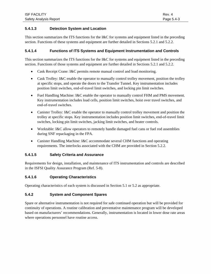
ISF FACILITY Safety Analysis Report
Rev. 4 Page 5.4-3
5.4.1.3 Detection System and Location
This section summarizes the ITS functions for the I&C for systems and equipment listed in the preceding section. Functions of these systems and equipment are further detailed in Sections 5.2.1 and 5.2.2.
5.4.1.4 Functions of ITS Systems and Equipment Instrumentation and Controls
This section summarizes the ITS functions for the I&C for systems and equipment listed in the preceding section. Functions of those systems and equipment are further detailed in Sections 5.2.1 and 5.2.2.
• Cask Receipt Crane: I&C permits remote manual control and load monitoring.
• Cask Trolley: I&C enable the operator to manually control trolley movement, position the trolley at specific stops, and operate the doors to the Transfer Tunnel. Key instrumentation includes position limit switches, end-of-travel limit switches, and locking pin limit switches.
• Fuel Handling Machine: I&C enable the operator to manually control FHM and PMS movement. Key instrumentation includes load cells, position limit switches, hoist over travel switches, and end-of-travel switches.
• Canister Trolley: I&C enable the operator to manually control trolley movement and position the trolley at specific stops. Key instrumentation includes position limit switches, end-of-travel limit switches, locking pin limit switches, jacking limit switches, and heater controls.
• Worktable: I&C allow operators to remotely handle damaged fuel cans or fuel rod assemblies during SNF repackaging in the FPA.
• Canister Handling Machine: I&C accommodate several CHM functions and operating requirements. The interlocks associated with the CHM are provided in Section 5.2.2.
5.4.1.5 Safety Criteria and Assurance
Requirements for design, installation, and maintenance of ITS instrumentation and controls are described in the ISFSI Quality Assurance Program (Ref. 5-8).
5.4.1.6 Operating Characteristics
Operating characteristics of each system is discussed in Section 5.1 or 5.2 as appropriate.
5.4.2 System and Component Spares
Spare or alternative instrumentation is not required for safe continued operation but will be provided for continuity of operations. A routine calibration and preventative maintenance program will be developed based on manufacturers’ recommendations. Generally, instrumentation is located in lower dose rate areas where operations personnel have routine access.

ISF FACILITY Safety Analysis Report
Rev. 4 Page 5.4-4
THIS PAGE INTENTIONALLY LEFT BLANK.
ISF FACILITY Safety Analysis Report
Rev. 4 Page 5.5-1
5.5 CONTROL ROOM AND CONTROL AREAS
All activities at the ISF Facility are commanded, controlled and monitored from local control stations. Activities such as trolley control, FHM operation, CHM operations, and cask receipt crane operations are controlled locally by trained and qualified operations personnel. The local control stations allow an operator to fully comply with the safety and functional requirements of the systems and equipment under control. Interlocks to other systems and equipment, alarms and protective actions are included as appropriate. Accordingly, a centralized control room is not required.
The ISF does include an Operations Monitoring Area on the upper floor of the Administration Area. The Operations Monitoring Area uses an IDCS for centralized acquisition, processing, and storage of facility data. It is a data monitoring system only, and does not provide control functions. The IDCS is not necessary to maintain the conditions required to store SNF safely or to prevent damage to the SNF during handling and storage. Therefore, the IDCS is categorized Not Important to Safety. Section 4.3 provides more detail on the IDCS.
The ISF Facility is designed so that electrical power is not required for ITS structures, systems and components to perform their intended safety function. Manual capability ensures that the SNF can be placed in a safe condition if an off-normal event or accident does occur. As a result, no unique features or redundancy are required even if the operations monitoring area or local control stations are removed from service and cannot be occupied.
During emergencies, which require activation of the ISF Facility Emergency Plan, the Operations Monitoring Area serves as the Command Post (Ref. 5-9).

ISF FACILITY Safety Analysis Report
Rev. 4 Page 5.5-2
THIS PAGE INTENTIONALLY LEFT BLANK.

ISF FACILITY Safety Analysis Report
Rev. 4 Page 5.6-1
5.6 ANALYTICAL SAMPLING
Analytical sampling is not required to verify that operation of the ISF Facility is within prescribed limits. The methods used to verify operations within prescribed limits include:
• general area radiation and airborne radioactivity monitoring
• area specific radiation surveys
• effluent release monitoring
• sampling of Transfer Cask atmosphere
General area and airborne radioactivity monitoring are discussed in Section 7.3. Section 7.5 discusses the methods, frequencies, and plans for conducting radiation surveys. Section 7.6 describes the program for monitoring and estimating the contribution of radioactive materials to the environment.
Section 5.1.1 describes the sampling of the Transfer Cask atmosphere.
Helium will be provided by a vendor with accompanying documentation to verify purity meets the requirements for helium backfill gas. ISF procedures and quality assurance requirements will verify vendor documentation prior to use of fill gas.
Liquid waste will be sampled and levels of radioactive material contained in the liquid waste storage tanks shall be evaluated. Concentration will be limited to minimize radiation exposure and keep levels within any limits imposed by processor. The ISF will have all liquid waste processed and disposed of by vendor.

ISF FACILITY Safety Analysis Report
Rev. 4 Page 5.6-2
THIS PAGE INTENTIONALLY LEFT BLANK.
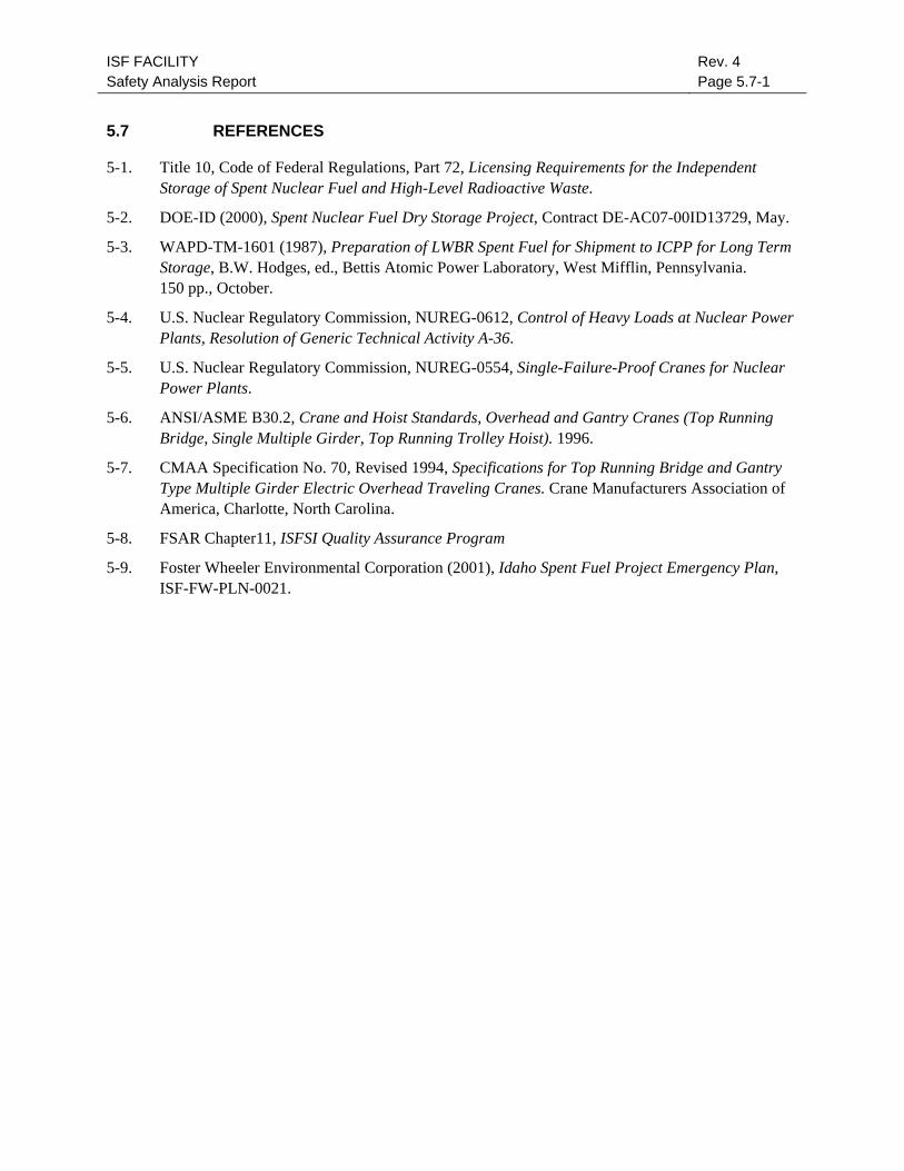
ISF FACILITY Safety Analysis Report
Rev. 4 Page 5.7-1
5.7 REFERENCES
5-1. Title 10, Code of Federal Regulations, Part 72, Licensing Requirements for the Independent Storage of Spent Nuclear Fuel and High-Level Radioactive Waste.
5-2. DOE-ID (2000), Spent Nuclear Fuel Dry Storage Project, Contract DE-AC07-00ID13729, May.
5-3. WAPD-TM-1601 (1987), Preparation of LWBR Spent Fuel for Shipment to ICPP for Long Term Storage, B.W. Hodges, ed., Bettis Atomic Power Laboratory, West Mifflin, Pennsylvania. 150 pp., October.
5-4. U.S. Nuclear Regulatory Commission, NUREG-0612, Control of Heavy Loads at Nuclear Power Plants, Resolution of Generic Technical Activity A-36.
5-5. U.S. Nuclear Regulatory Commission, NUREG-0554, Single-Failure-Proof Cranes for Nuclear Power Plants.
5-6. ANSI/ASME B30.2, Crane and Hoist Standards, Overhead and Gantry Cranes (Top Running Bridge, Single Multiple Girder, Top Running Trolley Hoist). 1996.
5-7. CMAA Specification No. 70, Revised 1994, Specifications for Top Running Bridge and Gantry Type Multiple Girder Electric Overhead Traveling Cranes. Crane Manufacturers Association of America, Charlotte, North Carolina.
5-8. FSAR Chapter11, ISFSI Quality Assurance Program
5-9. Foster Wheeler Environmental Corporation (2001), Idaho Spent Fuel Project Emergency Plan, ISF-FW-PLN-0021.

ISF FACILITY Safety Analysis Report
Rev. 4 Page 5.7-2
THIS PAGE INTENTIONALLY LEFT BLANK.
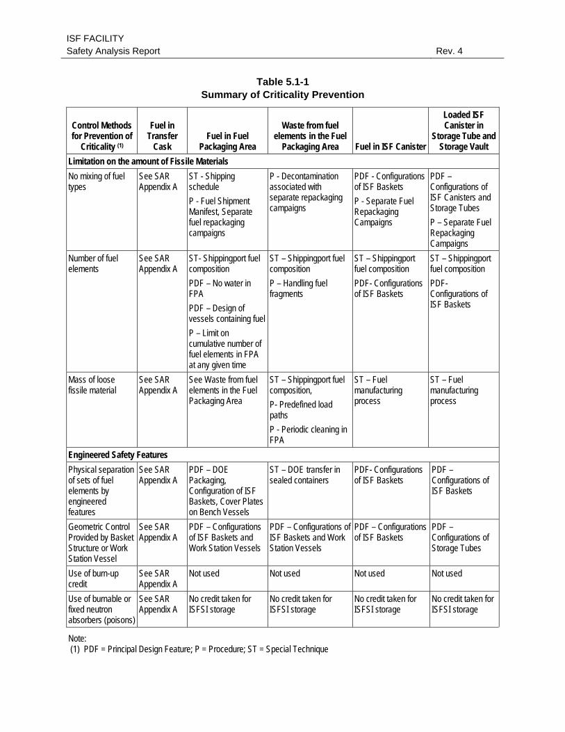
ISF FACILITY Safety Analysis Report Rev. 4
Table 5.1-1 Summary of Criticality Prevention
Control Methods for Prevention of
Criticality (1)
Fuel in Transfer
Cask Fuel in Fuel
Packaging Area
Waste from fuel elements in the Fuel
Packaging Area Fuel in ISF Canister
Loaded ISF Canister in
Storage Tube and Storage Vault
Limitation on the amount of Fissile Materials No mixing of fuel types
See SAR Appendix A
ST - Shipping schedule P - Fuel Shipment Manifest, Separate fuel repackaging campaigns
P - Decontamination associated with separate repackaging campaigns
PDF - Configurations of ISF Baskets P - Separate Fuel Repackaging Campaigns
PDF – Configurations of ISF Canisters and Storage Tubes P – Separate Fuel Repackaging Campaigns
Number of fuel elements
See SAR Appendix A
ST- Shippingport fuel composition PDF – No water in FPA PDF – Design of vessels containing fuel P – Limit on cumulative number of fuel elements in FPA at any given time
ST – Shippingport fuel composition P – Handling fuel fragments
ST – Shippingport fuel composition PDF- Configurations of ISF Baskets
ST – Shippingport fuel composition PDF- Configurations of ISF Baskets
Mass of loose fissile material
See SAR Appendix A
See Waste from fuel elements in the Fuel Packaging Area
ST – Shippingport fuel composition, P- Predefined load paths P - Periodic cleaning in FPA
ST – Fuel manufacturing process
ST – Fuel manufacturing process
Engineered Safety Features Physical separation of sets of fuel elements by engineered features
See SAR Appendix A
PDF – DOE Packaging, Configuration of ISF Baskets, Cover Plates on Bench Vessels
ST – DOE transfer in sealed containers
PDF- Configurations of ISF Baskets
PDF – Configurations of ISF Baskets
Geometric Control Provided by Basket Structure or Work Station Vessel
See SAR Appendix A
PDF – Configurations of ISF Baskets and Work Station Vessels
PDF – Configurations of ISF Baskets and Work Station Vessels
PDF – Configurations of ISF Baskets
PDF – Configurations of Storage Tubes
Use of burn-up credit
See SAR Appendix A
Not used Not used Not used Not used
Use of burnable or fixed neutron absorbers (poisons)
See SAR Appendix A
No credit taken for ISFSI storage
No credit taken for ISFSI storage
No credit taken for ISFSI storage
No credit taken for ISFSI storage
Note: (1) PDF = Principal Design Feature; P = Procedure; ST = Special Technique
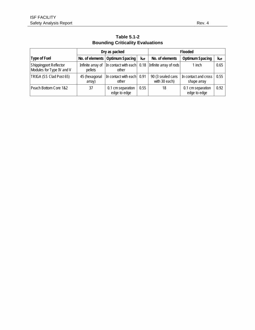
ISF FACILITY Safety Analysis Report Rev. 4
Table 5.1-2 Bounding Criticality Evaluations
Dry as packed Flooded Type of Fuel No. of elements Optimum Spacing keff No. of elements Optimum Spacing keff Shippingport Reflector Modules for Type IV and V
Infinite array of pellets
In contact with each other
0.18 Infinite array of rods 1 inch 0.65
TRIGA (SS Clad Post 65) 45 (hexagonal array)
In contact with each other
0.91 90 (3 sealed cans with 30 each)
In contact and cross shape array
0.55
Peach Bottom Core 1&2 37 0.1 cm separation edge to edge
0.55 18 0.1 cm separation edge to edge
0.92
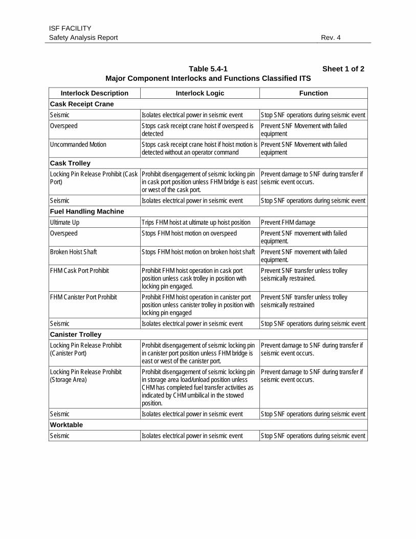
ISF FACILITY Safety Analysis Report Rev. 4
Table 5.4-1 Sheet 1 of 2Major Component Interlocks and Functions Classified ITS
Interlock Description Interlock Logic Function Cask Receipt Crane Seismic Isolates electrical power in seismic event Stop SNF operations during seismic event Overspeed Stops cask receipt crane hoist if overspeed is
detected Prevent SNF Movement with failed equipment
Uncommanded Motion Stops cask receipt crane hoist if hoist motion is detected without an operator command
Prevent SNF Movement with failed equipment
Cask Trolley Locking Pin Release Prohibit (Cask Port)
Prohibit disengagement of seismic locking pin in cask port position unless FHM bridge is east or west of the cask port.
Prevent damage to SNF during transfer if seismic event occurs.
Seismic Isolates electrical power in seismic event Stop SNF operations during seismic event Fuel Handling Machine Ultimate Up Trips FHM hoist at ultimate up hoist position Prevent FHM damage Overspeed Stops FHM hoist motion on overspeed Prevent SNF movement with failed
equipment. Broken Hoist Shaft Stops FHM hoist motion on broken hoist shaft Prevent SNF movement with failed
equipment. FHM Cask Port Prohibit Prohibit FHM hoist operation in cask port
position unless cask trolley in position with locking pin engaged.
Prevent SNF transfer unless trolley seismically restrained.
FHM Canister Port Prohibit Prohibit FHM hoist operation in canister port position unless canister trolley in position with locking pin engaged
Prevent SNF transfer unless trolley seismically restrained
Seismic Isolates electrical power in seismic event Stop SNF operations during seismic event Canister Trolley Locking Pin Release Prohibit (Canister Port)
Prohibit disengagement of seismic locking pin in canister port position unless FHM bridge is east or west of the canister port.
Prevent damage to SNF during transfer if seismic event occurs.
Locking Pin Release Prohibit (Storage Area)
Prohibit disengagement of seismic locking pin in storage area load/unload position unless CHM has completed fuel transfer activities as indicated by CHM umbilical in the stowed position.
Prevent damage to SNF during transfer if seismic event occurs.
Seismic Isolates electrical power in seismic event Stop SNF operations during seismic event Worktable Seismic Isolates electrical power in seismic event Stop SNF operations during seismic event
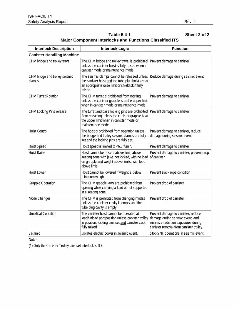
ISF FACILITY Safety Analysis Report Rev. 4
Table 5.4-1 Sheet 2 of 2Major Component Interlocks and Functions Classified ITS
Interlock Description Interlock Logic Function Canister Handling Machine CHM bridge and trolley travel The CHM bridge and trolley travel is prohibited
unless the canister hoist is fully raised when in canister mode or maintenance mode.
Prevent damage to canister
CHM bridge and trolley seismic clamps
The seismic clamps cannot be released unless the canister hoist and the tube plug hoist are at an appropriate raise limit or shield skirt fully raised.
Reduce damage during seismic event
CHM Turret Rotation The CHM turret is prohibited from rotating unless the canister grapple is at the upper limit when in canister mode or maintenance mode.
Prevent damage to canister
CHM Locking Pins release The turret and base locking pins are prohibited from releasing unless the canister grapple is at the upper limit when in canister mode or maintenance mode.
Prevent damage to canister
Hoist Control The hoist is prohibited from operation unless the bridge and trolley seismic clamps are fully set and the locking pins are fully set.
Prevent damage to canister, reduce damage during seismic event
Hoist Speed Hoist speed is limited to <6.3 ft/min. Prevent damage to canister Hoist Raise Hoist cannot be raised: above limit, above
seating zone with jaws not locked, with no load on grapple and weight above limits, with load above limit.
Prevent damage to canister, prevent drop of canister
Hoist Lower Hoist cannot be lowered if weight is below minimum weight
Prevent slack rope condition
Grapple Operation The CHM grapple jaws are prohibited from opening while carrying a load or not supported in a seating zone.
Prevent drop of canister
Mode Changes The CHM is prohibited from changing modes unless the canister cavity is empty and the tube plug cavity is empty.
Prevent drop of canister
Umbilical Condition The canister hoist cannot be operated at load/unload port position unless canister trolley in position, locking pins set and canister cask fully raised.(1)
Prevent damage to canister, reduce damage during seismic event, and minimize radiation exposures during canister removal from canister trolley.
Seismic Isolates electric power in seismic event. Stop SNF operations in seismic event Note: (1) Only the Canister Trolley pins set interlock is ITS.

ISF FACILITY Safety Analysis Report Rev. 4
Figure 5.1-1 General Arrangement of Areas
figure 5.1-01 (30110-1-3).doc
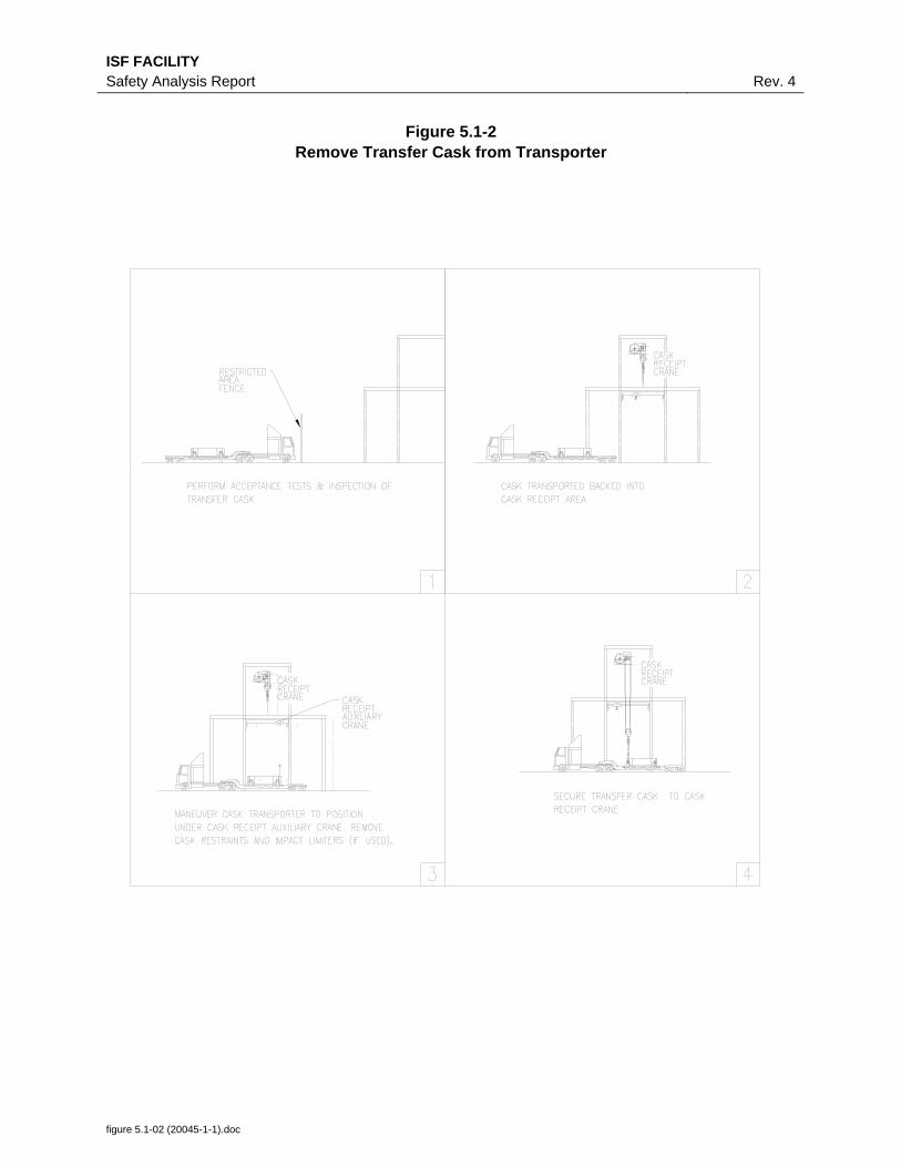
ISF FACILITY Safety Analysis Report Rev. 4
figure 5.1-02 (20045-1-1).doc
Figure 5.1-2 Remove Transfer Cask from Transporter
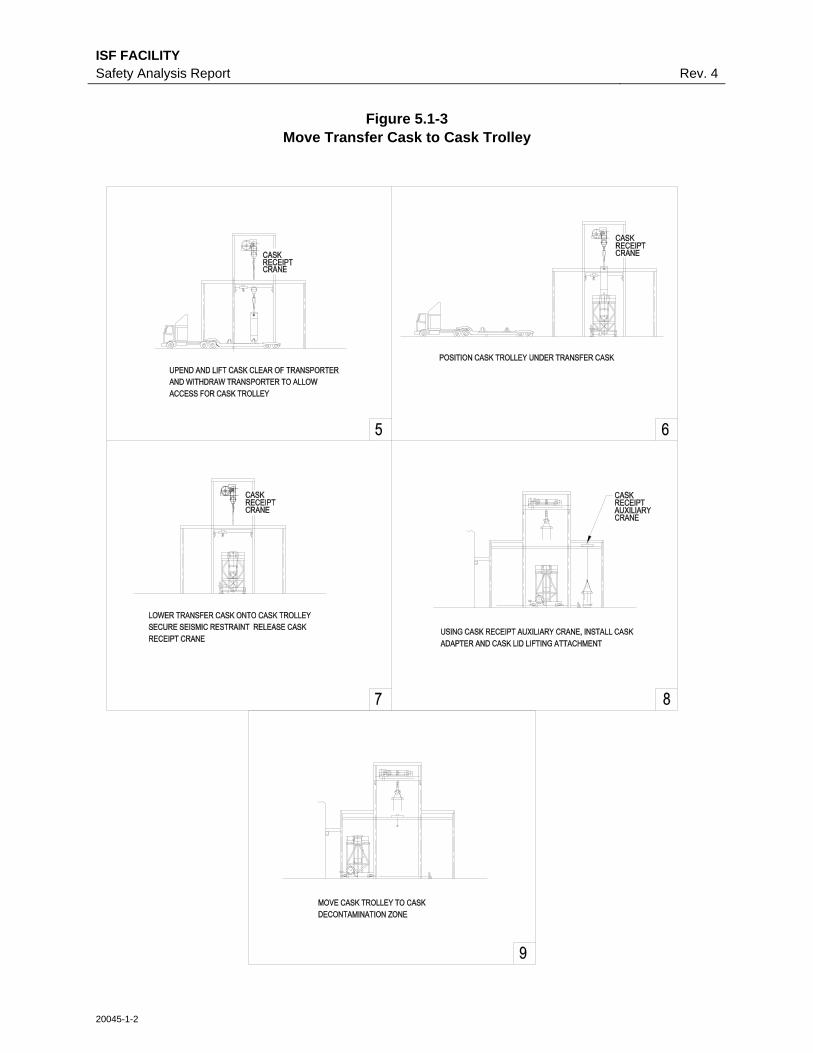
ISF FACILITY Safety Analysis Report Rev. 4
20045-1-2
Figure 5.1-3 Move Transfer Cask to Cask Trolley

ISF FACILITY Safety Analysis Report Rev. 4
Figure 5.1-4 Moving SNF To FPA And Return Transfer Cask To DOE
figure 5.1-04 (20036-1-1).doc

ISF FACILITY Safety Analysis Report Rev. 4
20180-2-1
Figure 5.1-5 Fuel Packaging Area Configuration
Peach Bottom 1 Fuel
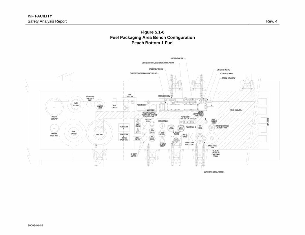
ISF FACILITY Safety Analysis Report Rev. 4
Figure 5.1-6 Fuel Packaging Area Bench Configuration
Peach Bottom 1 Fuel
20003-01-02
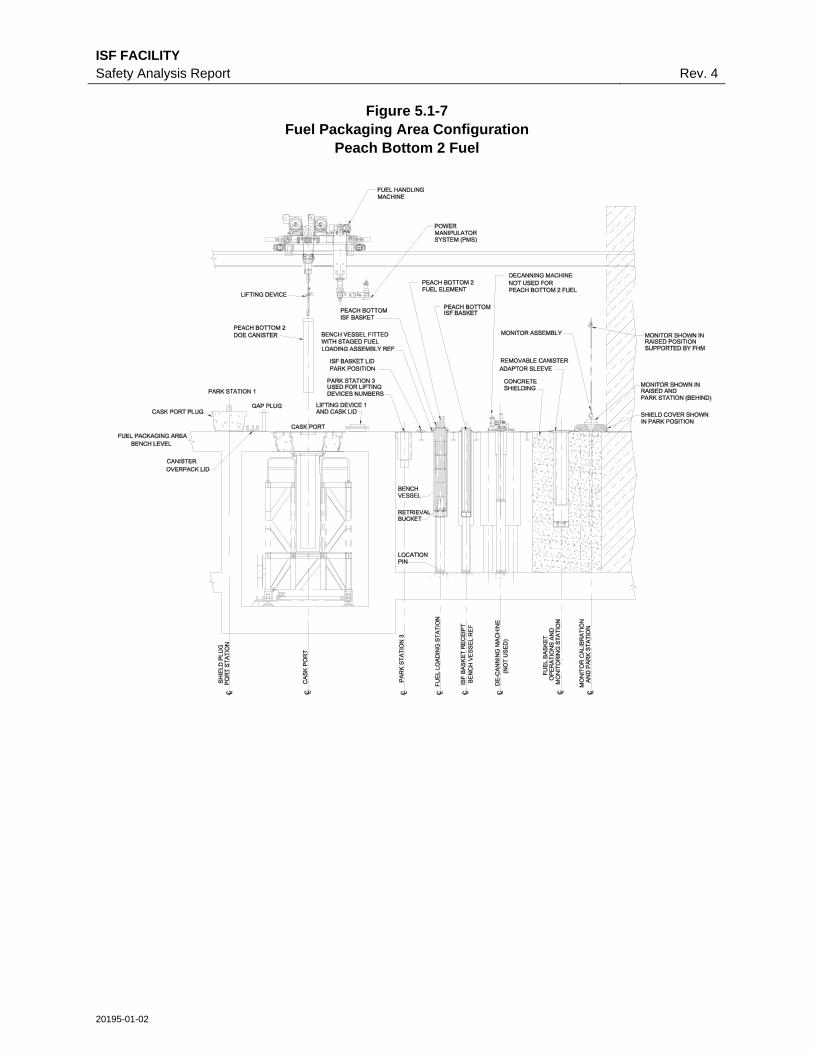
ISF FACILITY Safety Analysis Report Rev. 4
20195-01-02
Figure 5.1-7 Fuel Packaging Area Configuration
Peach Bottom 2 Fuel

ISF FACILITY Safety Analysis Report Rev. 4
Figure 5.1-8 Fuel Packaging Area Bench Configuration
Peach Bottom 2 Fuel
20182-1-1

ISF FACILITY Safety Analysis Report Rev. 4
20152-01-03
Figure 5.1-9 Fuel Packaging Area Configuration
TRIGA Fuel

ISF FACILITY Safety Analysis Report Rev. 4
Figure 5.1-10 Fuel Packaging Area Bench Configuration
TRIGA Fuel
20151-1-1
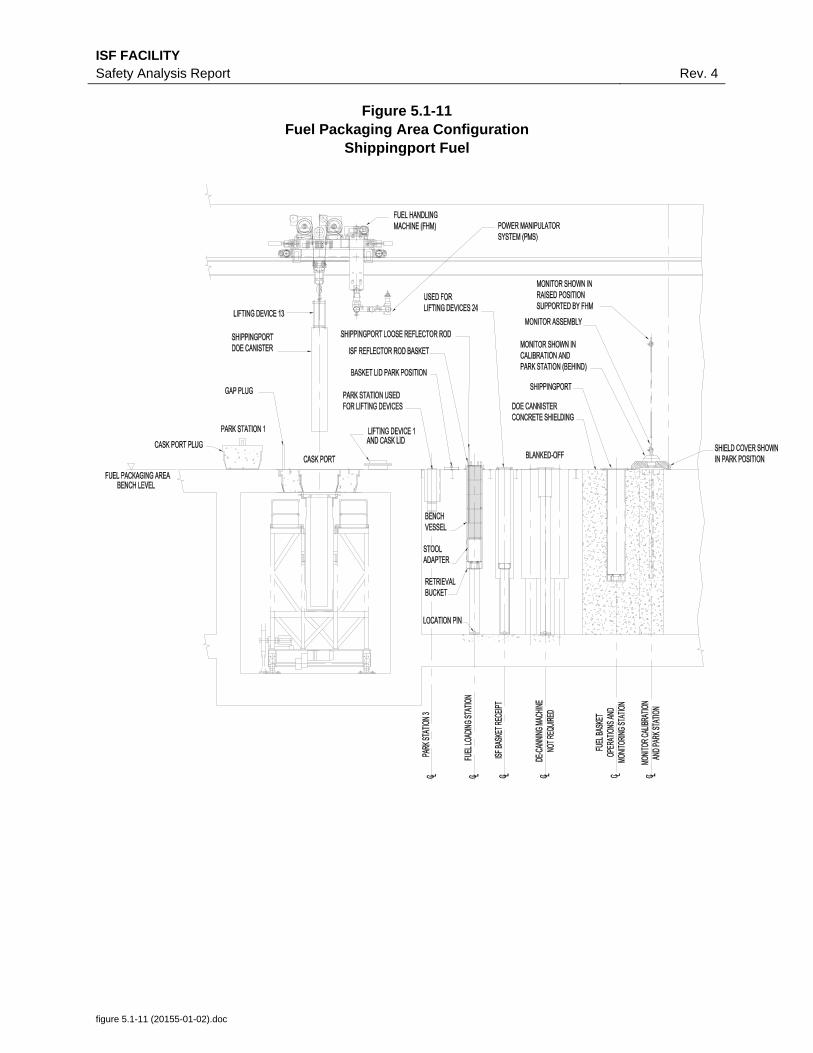
ISF FACILITY Safety Analysis Report Rev. 4
figure 5.1-11 (20155-01-02).doc
Figure 5.1-11 Fuel Packaging Area Configuration
Shippingport Fuel

ISF FACILITY Safety Analysis Report Rev. 4
Figure 5.1-12 Fuel Packaging Area Bench Configuration
Shippingport Fuel
20154-1-1

ISF FACILITY Safety Analysis Report Rev. 4
Figure 5.1-13 Canister Welding, Vacuum Dry, Helium Fill and Leak Check Layout
11127-04-02

ISF FACILITY Safety Analysis Report Rev. 4
Figure 5.1-14 ISF Canister Lid Closure Weld
figure 5.1-14 (11128-5-1).doc
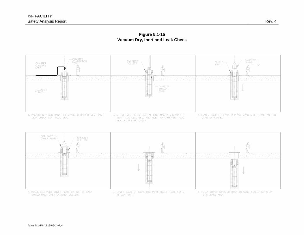
ISF FACILITY Safety Analysis Report Rev. 4
Figure 5.1-15 Vacuum Dry, Inert and Leak Check
figure 5.1-15 (11128-6-1).doc
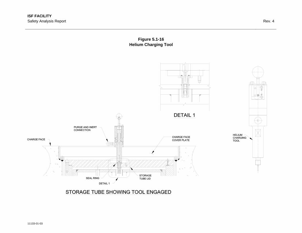
ISF FACILITY Safety Analysis Report Rev. 4
11133-01-03
Figure 5.1-16 Helium Charging Tool

ISF FACILITY Safety Analysis Report Rev. 4
Figure 5.1-17 Receipt and Storage of New ISF Canister
figure 5.1-17 (11128-1-1).doc
ISF FACILITY Safety Analysis Report Rev. 4
Figure 5.1-18
Figure Not Used.
figure 5.1-18 (11128-2-1).doc

ISF FACILITY Safety Analysis Report Rev. 4
Figure 5.1-19 Placement of New ISF Canister Into Canister Cask
figure 5.1-19 (11128-3-1).doc
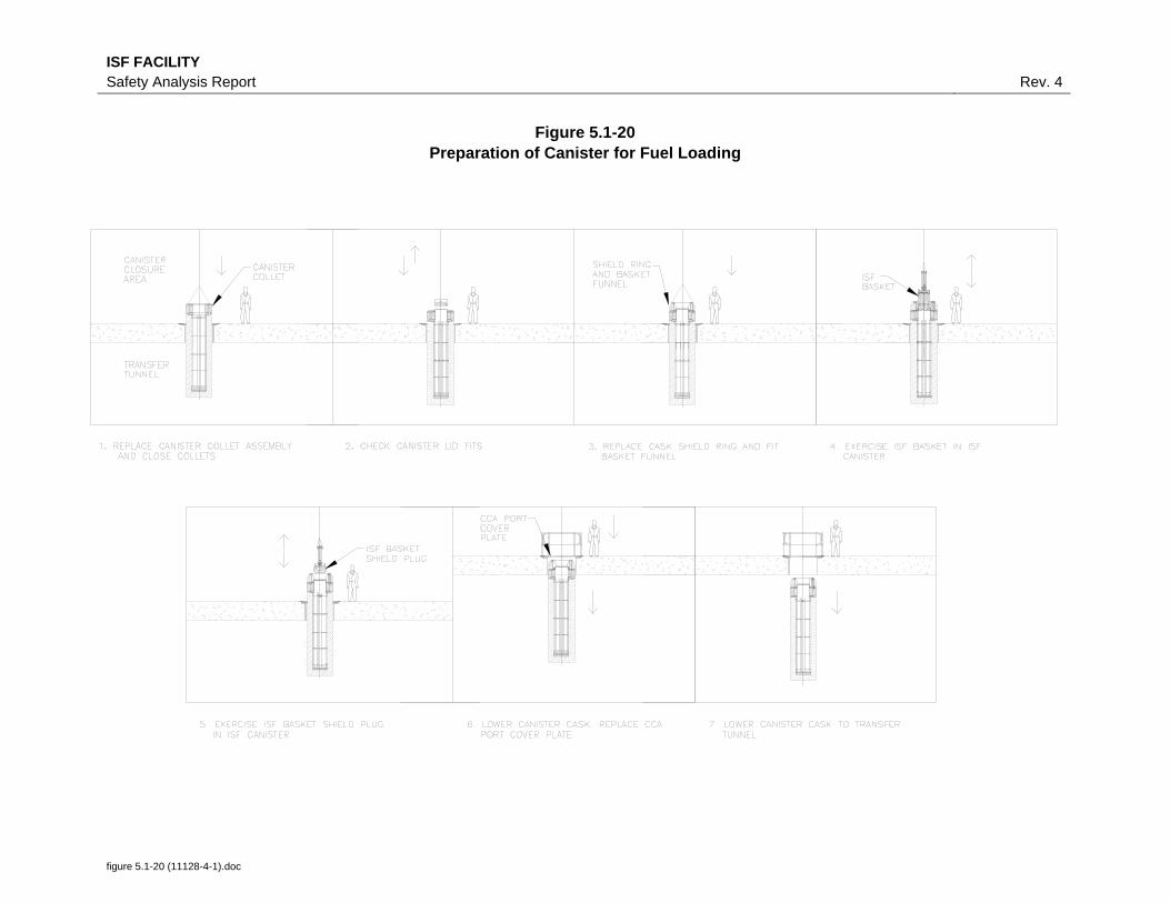
ISF FACILITY Safety Analysis Report Rev. 4
Figure 5.1-20 Preparation of Canister for Fuel Loading
figure 5.1-20 (11128-4-1).doc
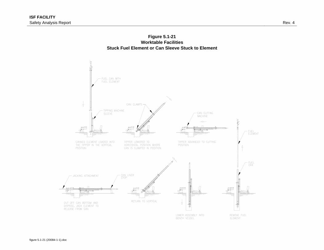
ISF FACILITY Safety Analysis Report Rev. 4
Figure 5.1-21 Worktable Facilities
Stuck Fuel Element or Can Sleeve Stuck to Element
figure 5.1-21 (20084-1-1).doc

ISF FACILITY Safety Analysis Report Rev. 4
Figure 5.1-22 Cask Receipt and Return
figure 5.1-22 (03020-1-1).doc

ISF FACILITY Safety Analysis Report Rev. 4
figure 5.1-23 (03020-3-1).doc
Figure 5.1-23 Peach Bottom 1 Fuel
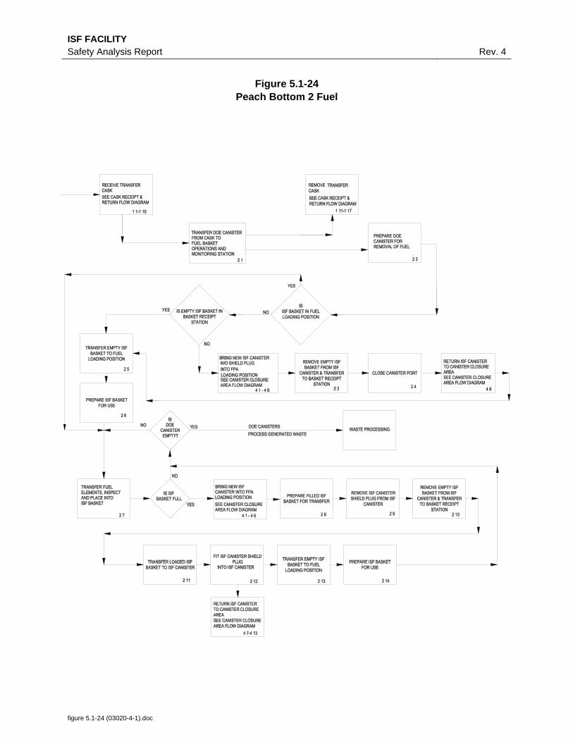
ISF FACILITY Safety Analysis Report Rev. 4
figure 5.1-24 (03020-4-1).doc
Figure 5.1-24 Peach Bottom 2 Fuel
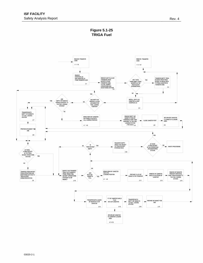
ISF FACILITY Safety Analysis Report Rev. 4
03020-2-1
Figure 5.1-25 TRIGA Fuel
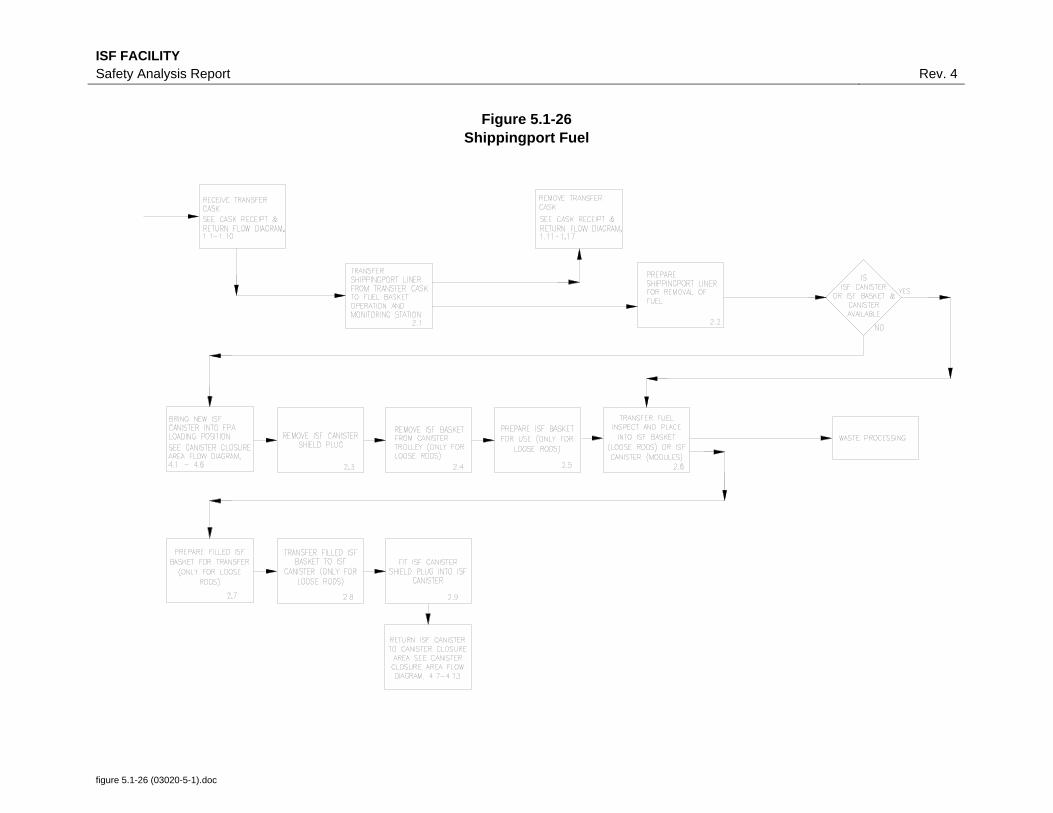
ISF FACILITY Safety Analysis Report Rev. 4
Figure 5.1-26 Shippingport Fuel
figure 5.1-26 (03020-5-1).doc

ISF FACILITY Safety Analysis Report Rev. 4
Figure 5.1-27 Canister Closure Area
figure 5.1-27 (03020-9-1).doc

ISF FACILITY Safety Analysis Report Rev. 4
figure 5.1-28 (03020-10-1).doc
Figure 5.1-28 Dry Store CHM Operation Sequence