
00261022
12
IEEE TRANSACTIONS ON POWER ELECTRONICS. VOL. n. NO 4. OCTOBER 1993 509 Techniques for Minimizing the Input Current Distortion of Current-Controlled Single-phase Boost Rectifiers John C. Salmon, Member-, IEEE Abstract-This paper describes techniques for minimizing the input current distortion of current-controlled single-phase boost rectifiers. The switching patterns of several boost rectifiers are examined to identify the nature of their input current waveforms. This analysis is then used to examine the low-frequency current distortion levels, and hence power quality, associated with the rectifiers. A PWM strategy that selectively switches between positive unipolar PWM and negative unipolar PWM, called “phase-adjusted unipolar PWM,” is shown to produce the lowest current distortion levels. A new 2-switch asymmetrical half- bridge rectifier is presented that draws an input current at a unity fundamental power factor and with the same low distortion as obtained with the 4-switch H-bridge rectifier. The operation of the various rectifiers is examined with reference to theoretical predictions, circuit simulations, and experimental results. This analysis, using a per-unit system based upon the magnitude of the rectifier inductor, is then used to compare the performance of the various rectifier switching patterns. I. INTRODUCTION INGLE-PHASE pulsewidth-modulated (PWM) rectifiers S have been the source of interest in the literature [I]-[ IO] over recent years. Tougher regulations on the harmonics gen- erated by electronic equipment, together with the lower cost of control circuits and power semiconductors, have made PWM boost rectifiers more attractive. Electric power utilities are also demonstrating a trend for restricting the harmonic pollution of the utility system. It is for these reasons that this paper is concerned with rectifier circuit topologies that control the rectifier input current waveshape to achieve unity power factor operation and very low current distortion levels. Several single-phase PWM boost rectifier topologies have been described in the literature, see Fig. 1 and [I]-[ IO]. The 1-switch bridge rectifier [see Fig. I(a) and (b)], has one ofthe simplest circuit structures. Typical voltage current waveforms for the circuit, using hysteresis current control, are shown in Fig. 2(a); the hysteresis band is made large in the figure for illustrative purposes. The 2-switch H-bridge rectifier (see Fig. I(c) and [4], [7]), performs the same switching action as the 1-switch rectifier but has the advantage of higher efficiency. The 4-switch H-bridge rectifier [see Fig. I(e)], can produce sinewave currents of a higher quality than Manuscript received February IO, 1992; revised Augu\t 1 I. 1993. This work was supported by the National Science and Engineering Rewarch Council. Canada. The author is with the Department of Electrical Engineering. Univervity of Albena. Edmonton, Alberta, Canada, T6G 2G7. IEEE Log Number 92 13634. - +E (d) Fig. 1. Single-phase PWM controlled boost rectifiers. (a) 1-switch bridge: ac-link inductor: (b) 1 -switch bridge: dc-link inductor; (c) 2-switch H-bridge; (d) 2-switch asymmetrical half-bridge. the I-switch rectifier [see Fig. 2(b)]. The operation of the 2-switch asymmetrical half-bridge rectifier is described in this paper and can be considered as a 2-switch, and hence low cost, altemative to the 4-switch H-bridge [see Figs. I(d) and 2(c)]. This new circuit topology [9] can achieve the 0885-8993/93$03.00 0 1993 IEEE
description
00261022
Transcript of 00261022

IEEE TRANSACTIONS ON POWER ELECTRONICS. VOL. n. N O 4. OCTOBER 1993 509
Techniques for Minimizing the Input Current Distortion of Current-Controlled
Single-phase Boost Rectifiers John C. Salmon, Member-, IEEE
Abstract-This paper describes techniques for minimizing the input current distortion of current-controlled single-phase boost rectifiers. The switching patterns of several boost rectifiers are examined to identify the nature of their input current waveforms. This analysis is then used to examine the low-frequency current distortion levels, and hence power quality, associated with the rectifiers. A PWM strategy that selectively switches between positive unipolar PWM and negative unipolar PWM, called “phase-adjusted unipolar PWM,” is shown to produce the lowest current distortion levels. A new 2-switch asymmetrical half- bridge rectifier is presented that draws an input current at a unity fundamental power factor and with the same low distortion as obtained with the 4-switch H-bridge rectifier. The operation of the various rectifiers is examined with reference to theoretical predictions, circuit simulations, and experimental results. This analysis, using a per-unit system based upon the magnitude of the rectifier inductor, is then used to compare the performance of the various rectifier switching patterns.
I. INTRODUCTION INGLE-PHASE pulsewidth-modulated (PWM) rectifiers S have been the source of interest in the literature [I]-[ I O ]
over recent years. Tougher regulations on the harmonics gen- erated by electronic equipment, together with the lower cost of control circuits and power semiconductors, have made PWM boost rectifiers more attractive. Electric power utilities are also demonstrating a trend for restricting the harmonic pollution of the utility system. It is for these reasons that this paper is concerned with rectifier circuit topologies that control the rectifier input current waveshape to achieve unity power factor operation and very low current distortion levels.
Several single-phase PWM boost rectifier topologies have been described in the literature, see Fig. 1 and [I]-[ IO]. The 1-switch bridge rectifier [see Fig. I(a) and (b)], has one ofthe simplest circuit structures. Typical voltage current waveforms for the circuit, using hysteresis current control, are shown in Fig. 2(a); the hysteresis band is made large in the figure for illustrative purposes. The 2-switch H-bridge rectifier (see Fig. I(c) and [4], [7]), performs the same switching action as the 1-switch rectifier but has the advantage of higher efficiency. The 4-switch H-bridge rectifier [see Fig. I(e)], can produce sinewave currents of a higher quality than
Manuscript received February IO, 1992; revised Augu\t 1 I . 1993. This work was supported by the National Science and Engineering Rewarch Council. Canada.
The author is with the Department of Electrical Engineering. Univervity of Albena. Edmonton, Alberta, Canada, T6G 2G7.
IEEE Log Number 92 13634.
- + E
(d)
Fig. 1. Single-phase PWM controlled boost rectifiers. (a) 1-switch bridge: ac-link inductor: (b) 1 -switch bridge: dc-link inductor; (c) 2-switch H-bridge; (d) 2-switch asymmetrical half-bridge.
the I-switch rectifier [see Fig. 2(b)]. The operation of the 2-switch asymmetrical half-bridge rectifier is described in this paper and can be considered as a 2-switch, and hence low cost, altemative to the 4-switch H-bridge [see Figs. I(d) and 2(c)]. This new circuit topology [9] can achieve the
0885-8993/93$03.00 0 1993 IEEE
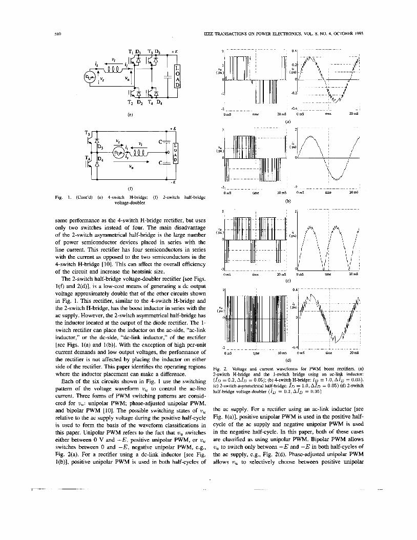
IEEE TRANSACTIONS ON POWER ELECTRONICS, VOL. 8, NO. 4, OCTOBER 1993 510
TI D, T3 D3 + E
T2 Dz T4 D4
+ E T3 -
L ' - E
-21 0 mS nme 2OmS OmS nmc 20 mS
(a)
31
(0 Fig. 1 . (Cont'd) (e ) 4-switch H-bridge; (f) 2-switch half-bridge
voltage-doubler.
same performance as the 4-switch H-bridge rectifier, but uses only two switches instead of four. The main disadvantage of the 2-switch asymmetrical half-bridge is the large number of power semiconductor devices placed in series with the line current. This rectifier has four semiconductors in series with the current as opposed to the two semiconductors in the 4-switch H-bridge [lo]. This can affect the overall efficiency of the circuit and increase the heatsink size.
The 2-switch half-bridge voltage-doubler rectifier [see Figs. l(f) and 2(d)], is a low-cost means of generating a dc output voltage approximately double that of the other circuits shown in Fig. 1. This rectifier, similar to the 4-switch H-bridge and the 2-switch H-bridge, has the boost inductor in series with the ac supply. However, the 2-switch asymmetrical half-bridge has the inductor located at the output of the diode rectifier. The 1- switch rectifier can place the inductor on the ac-side, "ac-link inductor," or the dc-side, "dc-link inductor," of the rectifier [see Figs. l(a) and l(b)]. With the exception of high per-unit current demands and low output voltages, the performance of the rectifier is not affected by placing the inductor on either side of the rectifier. This paper identifies the operating regions where the inductor placement can make a difference.
Each of the six circuits shown in Fig. 1 use the switching pattem of the voltage waveform U, to control the ac-line current. Three forms of PWM switching pattems are consid- ered for wu: unipolar PWM; phase-adjusted unipolar PWM, and bipolar PWM [lo]. The possible switching states of w, relative to the ac supply voltage during the positive half-cycle is used to form the basis of the waveform classifications in this paper. Unipolar PWM refers to the fact that w, switches either between 0 V and +E, positive unipolar PWM, or U, switches between 0 and -E, negative unipolar PWM, e.g., Fig. 2(a). For a rectifier using a dc-link inductor [see Fig. l(b)], positive unipolar PWM is used in both half-cycles of
-3 I 0 mS nmc MmS OmS m e 20 mS
(b)
31
0 mS m e 20mS OmS m c 20 mS
(C)
0 41
ume 20mS Oms m e 20 mS
(d)
Fig. 2. Voltage and current waveforms for PWM boost rectifiers. (a) 2;switch H-bcdge and the 1-switch bridge usigg an ac-linJ inductor: ( I D = 0.2, A I D = 0.05); (b) 4-switch H-bridge: I o = 1.0, AID = 0.05). (c) 2-switch asymmetrical half-bridge: ID E 1.0, A I D = 0.05) (d) 2-switch half-bridge voltage-doubler ( I o = 0 . 2 , A l ~ = 0.05)
the ac supply. For a rectifier using an ac-link inductor [see Fig. l(a)], positive unipolar PWM is used in the positive half- cycle of the ac supply and negative unipolar PWM is used in the negative half-cycle. In this paper, both of these cases are classified as using unipolar PWM. Bipolar PWM allows w, to switch only between +E and -E in both half-cycles of the ac supply, e.g., Fig. 2(d). Phase-adjusted unipolar PWM allows U, to selectively choose between positive unipolar

SALMON: SINGLE-PHASE BOOST RECTIFIERS 51 1
D.U. 0.” TABLE I POSSIBLE CONTROL STRATEGIES FOR PWM BOOST RECTIFIERS
PWM and negative unipolar PWM in both half-cycles of the ac supply (see Figs. 2(b) and 2(c) and [IO]). Phase-adjusted unipolar PWM is possible in rectifiers using ac-link and dc-link inductors.
The control methods that can be implemented in each of the five circuits in Fig. 1 are summarized in Table I. For example, the 4-switch H-bridge can be controlled to implement any one of the three PWM schemes whereas the 1-switch rectifier can only implement unipolar PWM. This paper investigates three forms of low-frequency current distortion that can occur as a result of using these PWM control methods:
1) Type I: Current distortion at the beginning of each half- cycle. This is caused by the ac-source voltage being too small to force the inductor current to follow a rising current demand.
2) Type II: This is caused by the output dc voltage being too small to force the current downwards when the inductor current is being decreased.
3) Type I l l : A combination of Types I and 11.
11. UNITY FUNDAMENTAL POWER FACTOR WITH LOW DISTORTION
This section uses “time-averaged’’ waveforms for identify- ing the conditions necessary for generating sinusoidal ac-line currents at unity power factor. A per-unit system is described to make the analysis applicable to all voltage and power levels.
A. Per-Unit System
follows: The base quantites for the per-unit system are defined as
Vbase = Ibase = vS/[uL] Zbase = w L fbase = f s ( 1 )
The following list defines the circuit parameters used in this paper together with their per-unit symbols (per-unit values are identified with a ‘‘-” located above the symbol):
uu,,21, Voltage waveform used to shape the line current. vS, Vs Source voltage. ID, f~ RMS demand current. E , E Output dc voltage. L, L Rectifier inductance. AI ; A r Current hysteresis band. VD,VD Demand voltage magnitude for ut,. I s , I , RMS ac-line current. f s , f s Supply frequency. This per-unit system places the per-unit output dc voltage
E at 1.414 (or J2) when the output dc voltage E is equal in magnitude to the peak of the ac input voltage (= J2Vs).
0
1 0 90 1 8 70 6 0
(a) (b)
Fig. 3. Time-averaged waveforms for distortionless unity power factor line current. (a) ac-link inductor. (b) dc-link inductor.
The rectifier output voltage is assumed in this paper to be ripple-free. The line current and demand current are scaled relative to the size of the rectifier inductor in the per-unit system chosen. This is a useful per-unit system since the ac-line current distortion is dependent upon the size of the inductance. The demand current waveform I D is assumed to be a sinusoidal waveshape in phase with the line voltage. A I is the peak magnitude of the current hysteresis band. The demand current magnitude ID is an important parameter and it is used as the reference variable for monitoring the line current distortion. The rectifier controller may request a specific current magnitude f ~ . but the actual rms line current drawn, Is. may differ owing to current distortion.
B. Waveforms for Unity Power Factor- Operation
The boost rectifier topologies shown in Fig. 1 can be reduced to two similar simplified forms, depending upon the inductor location (Fig. 3). An inductor, located in series with the ac-line voltage, or rectified voltage, and the PWM converter is used to shape the line current via controlling the shape of the voltage ii,. The rectifiers shown in Figs. I(a), l(c), l(e), and l(f) are associated with the simplified model shown in Fig. 3(a). The rectifiers shown in Figs. I(b) and (d) are associated with the simplified model shown in Fig. 3(b). The function of both models is identical except when the rectifiers are operated with a high per-unit current demand and a low output voltage. Note that the idealized waveforms are identical for both models over the positive half-cycle of the ac-supply.
The shape of V,, in Fig. 3 represents the “time-averaged waveform” required to force a I p.u. current through the inductor L ; the high-frequency components associated with li,, are neglected.
Considering the positive half-cycle of the ac voltage for both models, 6, is negative initially and positive over the rest of the half-cycle. This implies that the boost rectifier must be capable of producing negative and positive values for V u , in order to produce distortionless unity fundamental power

512
factor currents. The peak of Gu is larger than the-peak of the ac voltage. The output voltage of the rectifier E should always be greater than this peak to generate distortionless unity fundamental power factor current. Note that the peak of 6, is related to the magnitude of the current. These basic features form the basis of why the line current can experience low frequency distortion.
IEEE TRANSACTIONS ON POWER ELECTRONICS, VOL. 8, NO. 4, OCTOBER 1993
111. DISTORTION ANALYSIS
This section describes three types of low-frequency current distortion. The equations for the ac-line current are specified over the positive half-cycle of the ac voltage with the assump- tion that the circuit functions identically in both halves of the ac voltage cycle. The operating bounds between various waveform types are defined for demand currents covering the range 0 to 1 per-unit.
A . Distortion Types and Time-Averaged Circuit Waveforms
The time-averaged line current waveforms for the rectifiers are drawn in Fig. 4 using several assumptions. When the rectifier can not generate the desired voltage profile for G, (= demand voltage G D ) , then the voltage sticks at either 0 or kfi to try and force the current I, toward the demand current io. The current deviates from the demand for a while and then finally rejoins it. After this point, Gu then follows the ideal voltage profile G D and the line current 5, follows the demand current profile ;D. This action duplicates the action of a hysteresis current controller that tries to force the current to follow a desired current template.
There are three low-frequency distortion types that can occur:
Type I : The line current distorts at the beginning of each half-cycle [Fig. 4(a)]. In the positive cycle, this is caused by GD being less than zero while the rectifier can only generate zero voltage. This distortion occurs in unipolar PWM [IO]; hence, this distortion is commonly associated with the I-switch bridge and the 2-switch H-bridge rectifiers.
Type II: The line current distorts after the peak of the ac- line voltage [Fig. 4(b)-(d)]. This distortion is caused by GD exceeding the magnitude of the output dc voltage E. There are three line current waveforms that can occur for this distortion. Case A represents the situation when the line current rejoins the reference before the end of the half-cycle. Cases B and C represent the situation where this does not occur and the line current rejoins the demand current in the next half-cycle. This distortion type occurs in bipolar and phase-adjusted unipolar PWM; hence, the 2-switch half-bridge voltage doubler, the 2- switch asymmetrical half-bridge, and the 4-switch H-bridge rectifiers. The waveform for case B occurs when a dc-link inductor is used and the waveform for case C occurs when an ac-link inductor is used.
Type IIZ: This distortion type is a combination of Type I and I1 [Fig. 4(e)-(g)]. This distortion type is associated with unipolar PWM [IO] and is commonly associated with the 1- switch bridge and 2-switch H-bridge rectifiers. The waveform for case B occurs when a dc-link inductor is used and the waveform for case C occurs when an ac-link inductor is used.
~ . . -0.51
-21
(e) (0 (g)
Fig. 4. Time-averaged rectifier waveforms with low-frequency distortion. (a) Type 1; (b) Type 11, case A; (c) Type 11, case B; (d) Type 11, case C. (e) Type 111, case A; (f) Type 111, case B ; (9) Type III, case C.
B . Current Equations
The following analysis defines the functions goveming the line current waveshapes over several angular ranges; for example, a function may be valid over the angular range d = 0 + 0.8 refers to the angular position in the positive half-cycle of the ac mains voltage and, for this example, the function is valid for d ranging from 0' to CO.
Type I : This distortion type [see Fig. 4(a)] occurs in circuits employing a unipolar PWM control scheme, e.g., the 1- switch bridge and the 2-switch H-bridge rectifiers. The per-unit equations specifying the line current waveform for is and the voltage 6, are given by:
is =Jz. (1 -cosd) 0 5 d 5 p (2)
Is =Jz& . s in0 p 5 d 57r (3) G,=O 0 5 e 5 p (4)
G , = ~ z . d x . s i n [H-:] P < d < 7 r ( 5 )
Determining p : i S rejoins the demand current profile at angle p. p can be determined by-equating (2) with the demand current at d = p. Hence, with io given by:
i D = \ / Z . f D . s i n d (6 )

SALMON: SINGLE-PHASE BOOST RECTIFIERS 513
,O is given by:
Lj = 2 . tan-' [i,]
Papprox = [5 + 91 ID] degrees
( 7 )
A linear approximation to this equation (see [9]) is given by:
(8)
Type 11: Case A: This distortion occurs when the peak of V D exceeds E [see Fig. 4(b)]. Since the current distortion is caused by a low output voltage and no distortion occurs at the beginning of each half-cycle, this distortion occurs in circuits employing either phase-adjusted unipolar PWM or bipolar PWM [IO]. The line current departs from the reference at angle cy and then rejoins at angle $, where li, < T . The per- unit equations specifying the line current waveform for ;s and the voltage 6, are given by:
2, = J z . I , ' s ing o < 0 < (1 (9) is = Jz . [ I D . sin cy + (cos ( x - cos H ) ]
( 1 0 )
The ideal voltage for 7/, to give unity power factor is defined as being the demand voltage 6,:
6, = d a - s i r i [ 6 ' - g] (15)
When this equation matches E at angle ( Y . then the current starts to distorts. Hence, cy can be determined using the equation:
Integrating the difference between the demand, or desired, control voltage and actual voltage for ,ii, over the period ( Y to $, and equating the result to zero, will obtain the angle .li, at which the difference between the desired inductor volt-seconds and the actual volt-seconds is zero.
Type 11: Case B: This distortion occurs -when the peak of the demand voltage for V, ,VD. exceeds E [Fig. 4(c)]. The distortion is more extreme than the Type 11: case A and is present at high per-unit demand currents. This distortion occurs in circuits employing a dc-link inductor and using either phase-adjusted unipolar PWM or bipolar PWM, e.g., 2-switch asymmetrical half-bridge.
The source current departs from the reference at angle n and rejoins at an angle exceeding T . This angle is equivalent to U at the beginning of the half-cycle. The current equations are defined as follows:
i,s =io + (1 -cos81
- E . H o < e < o (19)
r , = J z . I , . s i n ~ m < ~ < r r (20) 3,q = Jz . [ I D . sin (1 + (cos (1 - cos 011
- E . ( O - t r ) r r < H < T (21) & = E o < e < a (22)
; , , , = E t X < H < T (24)
I , is the per-unit line current at the beginning of the half-cycle.
G , . = ~ ~ . s i n [ Q - ~ ] a < O < a (23)
An expression defining io is obtained by putting O = 17 in (21). This assumes that the inductor current is the same at 6' = 7r
as at H = 0". Hence:
i, = Jz . [ I D . sin (Y + (1 + cos a ) ] - E . ( T - C Y ) (25)
cr is obtained by equating (19) with (20) at 6' = o. Hence we get:
Jz . (cos o + i~ . sin a - 1) + E . o = Io (26)
a is obtained using (16). Type 11: Case C: This distortion is similar to the Type 11:
case B described above and occurs in circuits employing an ac- link inductor and using either phase-adjusted unipolar PWM or bipolar PWM, e.g., 4-switch H-bridge and the 2-switch half-bridge voltage-doubler rectifier.
The current equations are defined as follows:
;s = - i, + h ' ( 1 - cos6')
+ E . 8 O < H < U (27)
/ e = v [ d a . s i n ( 6 ' - : ) - I ? ] d 6 ' = 0 (17) I , is assumed to be a positive quantity and defined by (25).
8=n ; , = ~ ' 3 . I D . s i r i ~ a < ~ < r Y (28) The actual current rejoins the desired reference current profile at $. Given that (Y is known, this process will then define the value of $:
d a ' cos ($ - ;) - 4-
;, = Jz . [iD . sin (1 + (cos ( v - cos e ) ]
<I,, = - E 0 < 6' < m
- E . ( O - ( Y ) a < H < 7 r (29) (30)
o < 6' < cy (3 1) i l , , = d a . sin [" - :] + E . ($I - a ) = 0 (18) & = E ( 1 < 6 ' < T (32)
This is an equation that is best solved using numerical iterative techniques.
m is obtained from (26) provided the sign is changed on the E and io. n is obtained from (16).

514 IEEE TRANSACTIONS ON POWER ELECTRONICS, VOL. 8, NO. 4, OCTOBER 1993
Type Ill: Case A: This form of distortion [Fig. 4(e)], has both Type I and Type I1 distortion. Since the angle $, associated with Type I1 distortion, is less than 180", then Type I1 does not interfere with Type I and the location of the rectifier inductor does not affect the waveforms. Since it is assumed that 7 0 < 1, then p < 90" and Type I distortion does not interfere with Type I1 distortion. Unipolar PWM waveforms, such as in the 1-switch bridge and 2-switch H-bridge rectifiers, are susceptible to this distortion. Equations defining a, and 6, are given by:
Equations (7), (1 6), and (1 8) can be used for determining p, a, and $, respectively.
Type ZZZ: Case B: This form of distortion, associated with the rectifier having a dc-link inductor, is similar to Type 111: case A except that the inductor current is not forced to zero before the end of the half-cycle [Fig. 4(f)]. The 1- switch bridge rectifier using a dc-link inductor can produce this distortion type. The current rejoins the desired current template at 0 = 0. This has the effect of altering the current profile associated with the Type I distortion and the angle at which the current rejoins the template is now denoted p'. Note: for ID < 1, (3' < 90". Thus, the equations defining the current and voltage waveforms are as follows:
Equations (25) and (26) can be used to obtain io and U
respectively. p' is determined using the following equation:
fD . (sin 0 - sin 0') + (COS U - COS p') = 0 (48)
I 0.2 0 . 4 0.6 0.8 1
Fig. 5. Operating regions.
Type 111: Case C: This form of distortion is similar to Type 111: case B and is associated with the rectifier having an ac- link inductor [Fig. 4(g)]. This distortion type is produced by the 2-switch H-bridge and the 1 -switch bridge using an ac-link inductor.
The current begins the positive half-cycle at -io and decreases rapidly by conducting through the rectifier diodes D1 and 0 4 [Fig. l(c)]. Upon reaching zero magnitude at angle U , the hysteresis controller having switched T4 on from the beginning of the cycle, automatically applies a zero voltage loop through T4 and 0 2 . This increases the current in the positive direction. The current profile associated with the Type I distortion is altered and the angle at which the current rejoins the template is now denoted p'. Note that for most of the range 0 < ID < 1, that p' < 90". Thus, the current and voltage waveforms are defined by:
z, = - Io + JZ. (1 - COSO)
+ E . o o < o < f f (49) 7, = Jz . (cos 0 - cos e ) i , = J z . i D . s i n ~ / Y < s < a (51) 7, = Jz. [iD . sin cy + (cos Q - cos e ) ]
- E . ( O - c y ) a < e < 7 r (52) & = - E o < o < u (53)
0 < 0 < p' (50)
G , = E c Y < o < 7 r (56)
Equation (25) can be used to obtain io. U and p' are determined using the following equations:
Jz. (1 - cosa) + E . U = io i D . sinp' + cosp' - cos0 = o
(57) (58 )
C . Operating Bounds
Unipolar PWM can experience distortion Types I and 111. This section identifies the operating regions and boundaries over which the two distortion types can occur for unipolar PWM when a dc-link inductor is used in the 1-switch bridge rectifier. The operating regions are also related to the distortion types of each of the rectifiers and to the performance of bipolar and phase-adjusted unipolar PWM.
There are three operating regions (Fig. 5 ) , with two bound- aries separating the regions. Fig. 6 shows the "time-averaged''

SALMON: SINGLE-PHASE BOOST RECTIFIERS 515
1.0*d2 I 1.2*42 I 1.4*d2 I
90 180 1 90 180 1 1 1. 5,P.u. I
0.75 0
- 1
e o
.5 "J\ 0 ' .no
e o
90 180 0
e o
0 .5 1 f i ,'
180 1 . 5 I A 0'
0 .5 (I
0 ' 180 e o
90
1 .o
~ Key: i; = ---- i,= - 1 Fig. 6. Current waveforms using unipolar PWM and the inductor located on the dc-side of the rectifier.
current waveforms over a range of demand current magnitudes and output voltages, for the positive half-cycle and for the 1-switch bridge rectifier using a dc-link inductor.
Region 1: The output dc voltage is much larger than the peak of the demand voltage V D required to maintain a unity power factor sinusoidal current. For the 1-switch bridge and the 2-switch H-bridge, Type I distortion occurs (Fig. 6 with E = 1.4 * J2.) If bipolar or phase-adjusted unipolar were adopted, then this region would generate sinusoidal currents with no low frequency distortion.
Boundary I: The boundary between region 2 and region 1 o5curs when the peak value for the demand voltage V D reaches E. Given a per-unit current demand of f ~ , the peak value of the desired voltage for V, in per-unit is:
VD,,,, = JG (59)
This boundary represents the minimum output voltage that should be used to eliminate low-frequency distortion when using the bipolar and phase-adjusted unipolar PWM strategies.
Region 2: For the 1-switch bridge and the 2-switch H- bridge, Type 111: case A distortion occurs (Fig. 4(e) and Fig. 6 with E = J2 and f~ = 0.5.) For the 1-switch asym- metrical half-bridge, 2-switch half-bridge voltage doubler, and the 4-switch H-bridge, using either bipolar or phase-adjusted unipolar PWM, Type 11: case A distortion occurs [Fig. 4(b)].
Boundary 2: This boundary marks the instances when the current is reduced down to the reference waveform at exactly
the end of the half cycle: 1c, = 180". The relation between f~ and E on this boundary is found by \king the difference between the desired voltage curve for Vu and E and inte- grating over the period (Y to 180' [see (18)]. The following relationships are useful for manipulating this equation: From (7):
P 1 cos - = ~ JX
From (16):
Hence, the following expression can be obtained from (18) by solving for 1c, = 7r:
For f~ ranging between 0 and 1 and using numerical iterative techniques, a value for E can be found from (62) corresponding to boundary 2. The resultant curve is given in Fig. 5, marked boundary 2. The theoretical current waveforms are the same as for operation in region 11.

516 IEEE TRANSACTIONS ON POWER ELECTRONICS, VOL. 8, NO. 4, OCTOBER 1993
Region 3: For the 1-switch bridge using a dc-link induc- tor, Type 111: case B distortion occurs (Fig. 6 with E = 1 .2J2 , i~ = 1.0 For the 2-switch H-bridge and the 1-switch bridge using an ac-link inductor, Type 111: case C distortion occurs [Fig. 4(g)]. For the 1-switch asymmetrical half-bridge, using either bipolar or phase-adjusted unipolar PWM, Type 11: case B distortion occurs [Fig. 4(c)]. For the 2-switch half- bridge voltage-doubler and the 4-switch H-bridge, using either bipolar or phase-adjusted unipolar PWM, Type 11: case C distortion occurs [Fig. 4(d)].
Technically there is a third boundary corresponding to E = J2. The output voltage would not normally be reduced below this point.
D. Quality of the ac-Line Current Waveforms
The quality of the various current waveshapes can be investigated using Fourier analysis. This section presents the analysis for assessing the quality of the waveforms for the 1-switch bridge rectifier using a dc-link inductor and experi- encing distortion Type I and distortion Type 111: cases A and B. The equations associated with the remaining current wave- forms are complex and their performance are best analyzed using numerical techniques.
TypeI: Given the current equations (2) and (3), the per- unit rms fundamental components of the source current can be expressed in terms of the angle P:
P tan - (63)
(64)
Subscript a designates the real component and subscript b designates the imaginary component of Isl or in terms of the per-unit demand current ID :
Isla = -[n- 2 +sin@ - PI n- - 1
I s l b = -[sin@ - P] n-
The fundamental power factor FPF is defined by sion:
I s la FPF = cos41 = J K x
Substituting (63) and (64) into (67) gives:
(66)
the expres-
(67)
-2 -0.5
(68) 1
The rms of the line current is given by (69) (see below).
Given the equations for the fundamental components of the ac-line current and for the rms current (63), (64), and (69) (see below), respectively, then the ac-line current distortion can be obtained using:
The power factor of the ac-line current is defined as:
The total harmonic distortion is defined as:
I , is the total rms of the harmonic currents. Finally, the real component of the fundamental current, isla, is the component of the current that produces useful power.-The current demand ID represents the control requrest for Isla. The difference between the two parameters, A, represents an error introduced by current distortion:
(73)
Type I l l : Case A : The equations defining the various dis- tortion factors, (67), (70), (71), and (72) can be used to appraise the quality of this waveform [Fig. 4(e)], once the fundamental and total rms components of the current are known. Equations defining the current waveshape, (33), (34), and (39 , are needed for this analysis.
The real and imaginary components of the fundamental component of the ac-line current can be derived:
1 sin 2+ + sin 2 a 2
- sin(+ + a ) - sin(a - +) + Jz cos 274 + cos 2a
+-[l+ n- 2
(74)
1 - cos(a - +) -cos(+ + a )
2 . E - - [ ( a - + ) . c o s + + s i n + - s i n a ]
n-

SALMON: SINGLE-PHASE BOOST RECTIFIERS 517
1 C O S 2 . * + cos2 . a - cos(cy + $) + cos(a - 11)
2 + Jz sin 2 . + sin 2 . a
- - [ $ - a + 7r 2
1 + sin ( a - $) - sin ($ + a )
2 . E - - [ ($ -a ) . s in$
7r
+ cos * - cos cy] (75)
The equations defining the rms current and fundamental power factor can be derived in a similar fashion as used above, but the equations are unwieldy and are best examined using numerical techniques.
quality of the current waveforms in these cases were examined using the current equations defined above and with numerical programming, since the equations are long and do not give any significant insight; see (74) and (75) as an example.
Type 11: Cases A, B , C and Type Ill: Cases B . C The
Iv. EXPERIMENTAL RESULTS AND PERFORMANCE CURVES
This section examines the quality of the current waveforms produced in all the distortion types described in Section 111. Per-unit current demand magnitudes from 0 up to 1 per-unit were examined. Current hysteresis magnitudes were chosen to minimize the effect of high-frequency distortion, although this was difficult to achieve at low per-unit current demands for the experimental results. Spice was also used to obtain simulated results. Fig. 2 shows typical simulated circuit waveforms using a large hysteresis band.
The 1-switch bridge using a dc-link inductor was used to confirm the distortion Types I, 111: cases A and B. Distortion Types I, 111: cases A and C were examined using the 2-switch half-bridge. Note that the 1-switch bridge using an ac-link inductor obtains the same distortion patterns as the 2-switch H-bridge. Distortion Types 11: cases A and B were examined using the 2-switch asymmetrical half-bridge. Distortion Types 11: cases A and C were examined using the 4-switch H-bridge.
Fig. 7 shows some typical experimental waveforms for ' U ,
and is using the following circuits and PWM waveform types: 1) Unipolar PWM: 1-switch bridge with an ac-link inductor
[Fig. 7(a)]. 2) Bipolar PWM: 4-switch H-bridge [Fig. 7(b)]. 3) Phase-adjusted unipolar PWM: 4-switch H-bridge [Fig.
Reference [9] can be consulted for the detailed comparisons between experimental, simulated, and theoretical predictions of the current waveforms derived in Section 111.
7 ( 4 .
Type I The theoretical power factor and distortion factors CDF,
FPF, PF, THD, and error in the fundamental (A) are plotted
V U
ov
4
OA
= 50V for voltage H = 1mS
VU
Q V
= 1 A for current = lOOV for voltage
I l u l = l m P I
VU
ov
(c)
Fig. 7. Experimental waveforms. (a) Unipolar PWM-1-switch bridge with an ac-link inductor; (b) bipolar PWM4-swi tch H-bridge; (c) phase-adjusted unipolar P W M 4 - s w i t c h H-bridge.
in Fig. 8. The largest contributor to the power factor at low current demands is the CDF, but at high current demands FPF is the largest contributor. For an appreciation of the results shown in Fig. 8, consider the case of an overall acceptable current distortion of 5%. Assume that control circuit nonlinearity accounts for 1 % distortion; the supply voltage waveshape accounts for 1 % distortion; high switching frequency distortion accounts for another 1%. This leaves a maximum of 2% distortion allowable by the Type I distortion.

518 IEEE TRANSACTIONS ON POWER ELECTRONICS, VOL. 8, NO. 4, OCTOBER 1993
(a) (b)
PF; (b) THD, A. Fig. 8. Performance curves associated with Type I distortion. (a) CDF, FPF,
(c ) (d)
using a dc-link inductor. (a) THD; (b) P F (c) CDF (d) FF'F. Fig. 9. Performance curves for Type III distortion and the 1-switch rectifier
The maximum permissible current magnitude [Fig. 8(b)] under these conditions would be 0.14 p.u. This represents an actual current of 21.4 amps if a 115 V ac voltage is used with an inductance of 2 mH.
Type 111: Cases A and B: The three-dimensional plots of the THD, PF, CDF, and FPF
are shown in Fig. 9 as a function of the per-unit demand current and the per-unit output voltage.
Rectifier Distortion Curves: Fig. 10 shows the theoretical total harmonic distortion (THD) for all the rectifiers. The curves have been separated into two figures to illustrate the effect of using either a dc-link or an ac-link inductor. For instance, both the 4-switch H-bridge and the 2-switch asymmetrical half-bridge implement phase-adjusted unipolar PWM. The former uses an ac-link inductor and the latter uses a dc-link inductor. At high current magnitudes., the distortion of the rectifier using the dc-link inductor is greater than one using an ac-link inductor. This difference reduces at higher output voltages and at low current magnitudes.
The two plots in Fig. 10 show that phase-adjusted unipolar PWM can eliminate the low frequency distortion at low current magnitudes by using high output voltages. Unipolar PWM, however, is always prone to the low-frequency distortion unless very low current demands are used.
0 0.2 0.4 0.6 0.8 Id [ P.U. 1 1
(a) T H D ( % )
I ;' 1
2 o t
0 Id [ p.u. ) ' 0.2 0.4 0.6
(b)
PWM. (a) Phase-adjusted unipolar PWM, (b) unipolar PWM. Fig. 10. Theoretical THD using unipolar PWM and phase-adjusted unipolar
Experimental results were obtained using either 115 V, or a 60 V ac supply, with a 67 mH inductor. This produced a base current of just over 5 A for the 115 V 60 Hz supply. The inductor is very large for the power level under consideration (x575 W), but the circuit parameters permit a wide range of per-unit currents and operating conditions to be tested. Distortion of the ac-supply voltage (2-5%), nonlinear magnetic components, ac-line inductance, and measurement errors (Spectrum Analyzer) affected the accuracy of these results. However, general trends can be observed from the results (Figs. 11 and 12).
Simulation results were obtained using a very small hystere- sis band of peak-to-peak value 0.004 per-unit, (Figs. 11 and 12). This allowed the low-frequency distortion to be separated from the high-frequency distortion associated with the rectifier switching frequency.
The simulation results compared very favorably with the theoretical results and no significant differences can be ob- served (Figs. 11 and 12). The experimental results follow the general trends predicted from the theory and simulation results. The experimental distortion factors associated with using a dc- link inductor and high per-unit current demands [Figs. l l(a) and 12(a)] are lower than the predicted distortion figures. The differences can be attributed to measurement errors using a spectrum analyzer and to smoothing effects associated with the ac-line inductance. Tests, undertaken to decouple the ac-

SALMON: SINGLE-PHASE BOOST RECTIFIERS 519
THD { % 1 E = 1.042 P
I‘
,P‘ 1 5 i
0
5 4
Id { p.u. 1
0 0.2 0.4 0.6 0.8 1
(a)
2 o t E = l.l*lj2
1 5 i W
l o t 5 ! m b m - Jt”
0 0 Id ( p.u. ) +--
0 0 2 0.4 0.6 0.8 1
(b)
E = 1.2*d2 2 o t 1 0 1
1 5 4
0 0.2 0.4 0 .6 0.8 1
(C)
20 t E = 1.4*42
1 0 1
5t ’ Q 8 I d 0
~ 0: 0.2 0.4 ~ o0.6 0.d pJ’ )l 2-swirch asymmcuicical bridge 4-switch H-bridge ~
- - - - theoruical - t h d c a l I
ex-enlal expmmmlal
0 1 . - - - - - - - rimdared A rimulared
(d)
4-switch H-bridge.
I
. - 1
Fig. 11. Comparison of THD for 2-switch asymmetrical half-bridge and
line inductance using high-frequency capacitors, increased the distortion of the current drawn into the rectifier terminals. Thus when using a dc-link inductor, ac-line inductance will lower the current distortion levels below the predictions and will approach the predictions based upon using an ac-link inductance .
V. CONCLUSION Time-averaged waveforms were used to identify the line-
current waveforms associated with single-phase boost rectifier circuits. Three useful PWM switching pattems can be used in single-phase PWM rectifiers: positive unipolar PWM; bipolar PWM; and phase-adjusted unipolar PWM. This paper related three line current distortion types with these PWM switching pattems and the associated circuit topologies.
T H D ( % )
20 1 E = 1.042 I
1 5
0 0.2 0.4 0.6 0.8 1
Id { p.u. )
0 0.2 0.4 0.6 0.8 1
(b)
E = 1.242 20 *
0 0.2 0.4 0.6 0.8 1
(C)
E = 1.4*d2 0
2 4
1 5 t
Id { p.u. ) 0 I 0: simIl 0.4 I :.6 0.8 1,
1-switch with a &-I& i n d W
expcYi”lal u;paimcnul
2-switch H-bridge - - - - thcnctical - t h d d
A rimdared
(d)
Fig. 12. Comparison of THD for I-switch and 2-switch H-bridge.
Unipolar PWM, commonly associated with the 1-switch and 2-switch bridge rectifiers, is susceptible to Type I and Type I11 distortion types. The paper presented analysis that permits the rectifier current waveforms and performance to be predicted. With the performance curves derived, limits can be set on the minimum output dc voltage, boost inductor magnitude, and maximum per-unit demand current.
Bipolar PWM, typically associated with the 2-switch half- bridge voltage-doubler, can avoid generating Type I and Type I11 distortion. The paper identified a minimum output voltage that can be specified for any given per-unit current demand to guarantee that distortion Type I1 does not occur [see boundary 1 in Fig. 5 and (59)].
Phase-adjusted unipolar PWM switching pattems, associ- ated with the 4-switch H-bridge and the 2-switch asymmetrical half-bridge, permit the generation of optimal rectifier switching

520 IEEE TRANSACTIONS ON POWER ELECTRONICS, VOL. 8, NO. 4, OCTOBER 1993
pattems. These switching pattems can be used to eliminate Type I distortion. Equation (59) identifies a minimum output voltage that should be used for any given per-unit current demand to guarantee that distortion Type I1 does not occur. When using low current demand magnitudes, a desirable design choice for many reasons, the 2-switch asymmetrical half-bridge produces a similar high performance to that of the 4-switch H-bridge using only two switches rather than four. Using a high current demand, the 4-switch H-bridges produces a lower current distortion than the asymmetrical half-bridge.
Finally, this paper showed that when using a high per-unit current demand, an ac-link inductor should be used rather than a dc-link inductor to minimize the line current harmonic distortion. However, the natural inductance of the ac-supply can lower the differences between using a dc-link or an ac-link inductance.
ACKNOWLEDGMENT The author wishes to thank the University of Alberta for
providing facilities used in this work. Particular recognition is given to A. Huizinga for his patience and help in obtaining the experimental results in this paper.
I11
P I
[31
REFERENCES
M. F. Schlecht and B. A. Miwa, “Active power factor correction for switching power supplies,” IEEE Trans. Power Electron., vol. 2, pp.
M. Kazerani, P. D. Ziogas, and G. Joose, “A novel active current waveshaping technique for solid-state input power factor conditioners,” IEEE Trans. Indusr. Electron., vol. 38, pp. 72-78, Feb. 1991. A. R. Prasad, P. D. Ziogas, and S. Manias, “A novel passive wave- shaping method for single-phase diode rectifiers,” IEEE Trans. Indusr.
273-281, Oct. 1987.
R. Itoh and K. Ishizaka, “Single-phase sinusoidal converter using MOSFETS,” Proc. Inst. Elec. Eng., vol. 136, Part B, no. 5 , pp. 521-530, Sept. 1989, pp. 237-242. P. T. Krein, J. Bentsman, R. M. Bass, and B. L. Lesieutre, “On the use of averaging for the analysis of power electronic systems,” IEEE Trans. Power Elecrron., vol. 5 , pp. 182-190, Apr. 1990. A. W. Green and J. T. Boys, “Hysteresis current-forced three-phase voltage-sourced reversible rectifier,” Proc. Inst. Elec. Eng., vol. 136, Part B, no. 3, pp. 113-120, May 1989. -, “Current forced single-phase reversible rectifier,” Proc. Inst. Elec. Eng., vol. 136, Part B, no. 5 , pp. 205-212, Sept. 1989. L. Borle and J. C. Salmon, “A single-phase unity power factor soft switching resonant tank boost rectifier,” Proc. IEEE-IAS Annu. Meet., Oct. 1991, pp. 904-910. J. C. Salmon, “Performance of a single-phase pwm boost rectifier using hysteresis current control,” Euro. Power Electron. Conf., Sept. 1991,
-, “Circuit topologies for single-phase voltage-doubler boost recti- fiers,’’ IEEE PESC ‘92 Conf. Proc., 1992, pp. 549-556.
pp. 4-3844-389.
John C. Salmon (M’86) was born in Whitehaven, England, in 1960. He received the B.Sc.(Eng.) and Ph.D. degrees in electrical engineering from Impe- rial College, London, England, in 1982 and 1987, respectively. He received the M.Eng. degree at McGill University, Montreal, PQ, Canada, in 1984.
Since 1987, he has been at the University of Alberta, Edmonton, Canada, where he now holds the position of Associate Professor. His present research interests include power electronic circuit topologies, variable speed electric drives, PWh4 and resonant-
mode inverters and rectifiers. Dr. Salmon received the Willis Jackson Medal as an undergraduate student
at Imperial College, in 1982. He was a Commonwealth Scholar from 1982 to 1984. He is a member of the IEEE Industry Applications Society, IEEE Power Electronics Societv. IEEE Industrial Electronics Societv. IEEE-IAS Industrial
EleCtr&, vol. 37, Decr 1990. Power Converter Committee, and the IEEE-IAS IndusGal Drives Committee.


