002-3 Lesson Definitions, Background & Classification 3-12
21
1 Lesson 2 & 3 schnabel-eng.com Lesson 2 & 3 Definitions, Background, Classification, Applications and Costs Learning Outcomes Define a micropile Describe the characteristics, advantages and limitations of micropiles Describe the micropile classification system Describe the micropile classification system Identify factors influencing the choice and cost of micropile systems Background Definitions Two basic types of piles: Displacement piles: driven or vibrated into the ground thereby displacing the soil laterally during installation. during installation. Replacement piles: placed within a previously drilled borehole thus replacing the excavated ground.
Transcript of 002-3 Lesson Definitions, Background & Classification 3-12

1
Lesson 2 & 3
schnabel-eng.com
Lesson 2 & 3
Definitions, Background, Classification, Applications and Costs
Learning Outcomes
Define a micropileDescribe the characteristics, advantages and limitations of micropilesDescribe the micropile classification systemDescribe the micropile classification systemIdentify factors influencing the choice and cost of micropile systems
Background Definitions
Two basic types of piles:Displacement piles: driven or vibrated into the ground thereby displacing the soil laterally during installation.during installation.Replacement piles: placed within a previously drilled borehole thus replacing the excavated ground.

2
Micropiles Defined
Micropiles are replacement piles of small-diameter (typically less than 12 inch) that are
drilled, grouted and reinforced. The , greinforcement supports all or most of load.
Typical Micropile Capacities
Over 500+ tons in rock20 to 200 tons in soilStructural capacity usually governs designMicropile lengths are usually less than 100 ftMicropile lengths are usually less than 100 ft
Typical Micropile Construction Sequence Using Casing
ADDITIONAL GROUT
COMPRESSIBLESTRATUM
BEGIN DRILLING&/OR INSTALLATION
OF TEMPORARYCASING
COMPLETEDRILLING TO
DEPTH
REMOVE INNERDRILL BIT &
ROD (IF USED)
PLACEREINFORCEMENT &GROUT (BY TREMIE)
REMOVETEMPORARY
CASING, INJECTFURTHER GROUT
UNDERPRESSURE ASAPPLICABLE
COMPLETE PILE(CASING MAY BELEFT IN PLACETHROUGH THE
COMPRESSIBLESTRATUM)
BEARINGSTRATUM

3
Typical Micropile Working Conditions
Courtesy: Nicholson
Typical Working Conditions
Advantages of Micropiles
High capacity and relatively high stiffnessMinimal disturbance to adjacent structures, soil and the environment by noise and vibrationsvibrationsMay be installed in access-restrictive environmentsMay be installed in all soil and fill conditions

4
Advantages of Micropiles (cont.)
Installed at any angle below horizontalInstalled using same equipment as for anchor and grouting projectsMay be installed through existing foundationsMay be installed through existing foundations and close to existing structuresCan resist compression, tension, and/or lateral loads
Limitations of Micropiles
Lateral capacity limitations for vertical micropilesBecause of high slenderness ratio (length/diameter), may not be appropriate for(length/diameter), may not be appropriate for seismic retrofit (vertical micropiles)High lineal cost relative to conventional piling systems
Original Micropile (Palo Radici)

5
High Capacity Bars
High Capacity MicropileUSA 1980’s and Onwards
2-16
Courtesy: Hayward Baker
Micropile Classification Systems
A large number of historical/national/ proprietary names for micropiles
pali radicemicropalipmini pilespin pilesroot pilesneedle piles
This highlights the need for international standardization i.e., “micropile”
6
Classification System
1) Based on Design Concept designated by Case 1 or Case 2
2) Based on Groutingmethod of grout placement defines themethod of grout placement defines the grout/ground bond capacitydesignated by a letter A through D
To form a 2-part designator, e.g., Type 1A or Type 2B
Micropile Classification SystemBased on Design Concept
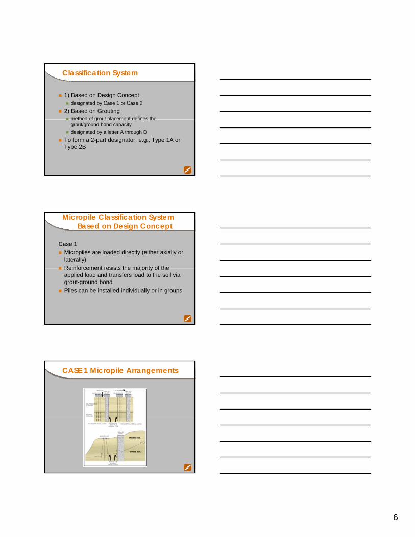
Case 1Micropiles are loaded directly (either axially or laterally)Reinforcement resists the majority of theReinforcement resists the majority of the applied load and transfers load to the soil via grout-ground bondPiles can be installed individually or in groups
CASE 1 Micropile Arrangements
7
Micropile Classification SystemBased on Design Concept
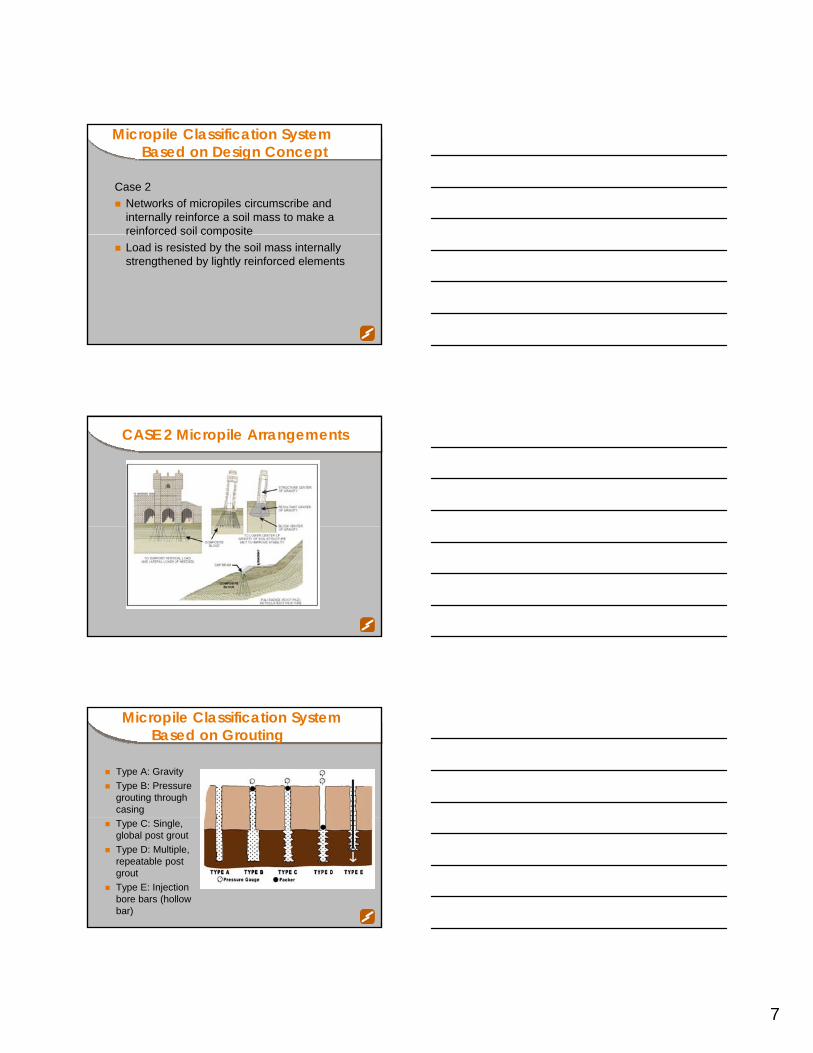
Case 2Networks of micropiles circumscribe and internally reinforce a soil mass to make a reinforced soil compositereinforced soil compositeLoad is resisted by the soil mass internally strengthened by lightly reinforced elements
CASE 2 Micropile Arrangements
Micropile Classification SystemBased on Grouting
Type A: GravityType B: Pressure grouting through casingType C: Single, global post groutType D: Multiple, repeatable post groutType E: Injection bore bars (hollow bar)

8
Type A Micropile
Grout is placed under gravity head onlyNeat cement grouts and sand-cement mortars used occasionally (Europe)Hole may be underreamed to increaseHole may be underreamed to increase capacity, although not now common
Type B Micropile
Grout is placed under pressure as casing or auger is withdrawnNeat cement grout usedInjection pressures of 75 to 150 psi usedInjection pressures of 75 to 150 psi used
Type C Micropile
Primary grout placed under gravity headSecondary grout placed prior to hardening one time via sleeved grout pipe without packer at pressure of at least 150 psi (“only”packer at pressure of at least 150 psi ( only in France)Neat cement grout used

9
Type D Micropile
Primary grout placed under gravity head or pressureSecondary grout placed after hardening via a sleeved grout pipe at pressure of 300 to 1,200sleeved grout pipe at pressure of 300 to 1,200 psi. Double packer used and secondary grouting may be repeated several times.Neat cement grout used
Structural Support Application
Structural SupportCASE 1
Earth RetainingStructure
Foundations
Foundations forNew Structures
Underpinning ofExisting
Structures
SeismicRetrofitting
Scour Protection
Repair/Replacement
of ExistingFoundations
Arresting/Prevention
of Movement
Upgrading ofFoundationCapacity
In-Situ Reinforcement Application
In-SituReinforcement
CASE 2
StructuralStability
Slope StabilizationAnd EarthRetention
GroundStrengthening
SettlementReduction

10
Micropiles for Foundation Support of Transportation Applications
Micropiles for Foundation Support of Transportation Applications
Micropile Drilling in New York
Williamsburg Bridge, NY (Nicholson)
Under the BQE, NY

11
Dulles Airport
Foundation Seismic Retrofit
Old Court House San Juan, PR
Seismic Retrofit for Bridge
Seattle, Washington

12
Seismic Retrofit of
Richmond /San Rafael Bridge, CA
2-42Courtesy: Agra Foundations
New Foundation for
Courtesy: Nicholson
Lewistown Bypass, PA
Micropile Stabilization
Mandalay Bay Hotel, Las Vegas, Nevada

13
Foundation Upgrading
Expansion of Exton Mall, Pennsylvania
Old PR-156 Bridge, Caguitas River, PR
Courtesy: Hayward Baker
Linn Cove Viaduct, NC
Deliver the Project ‘Top-downLimited exploration

14
Linn Cove Viaduct
Two uses for ‘Microshafts’Pier foundationsSliding resistance
In-Situ Reinforcement
Slope stabilization and earth retention (most common)Structural stabilizationGround strengthening and settlementGround strengthening and settlement reduction (least common)
State Road 4023 Slope Stabilization
Armstrong County, PA(Case 1 Design)

15
Case 1 Micropile Wall for Slope Stabilization
Case 1 Micropile Wall Construction
Wall 600 Permanent Earth Retention,
Portland, OR(Case 1 Design)

16
Slope Stabilization
FH-7, Mendocino National Forest, CA (Case 2 Design)
Reticulated Micropiles for Slope Stabilization
Mendocino County, California
Structural Stabilization
Mosul, Iraq (Case 2 Design)

17
Factors Influencing Micropile Selection
Physical Considerationsrestricted accessremote areasclose pile proximity to existing structures
Subsurface ConditionsSubsurface Conditionsdifficult and variable geologic conditionssusceptibility of ground to liquefaction during pile drivingobstructed soils or fillsexisting foundationshigh water table
Factors Influencing Micropile Selection
Environmental Conditionsvibration/noise sensitive areashazardous or contaminated soils
Existing Structure Adaptationi il b dd d t i ti ilmicropiles can be added to an existing pile cap
Courtesy: SPS
Typical Micropile Prices
Mob/demob $10,000 to $50,000/rigTesting
Sacrificial test $10,000 to $30,000 eachProof test $2,000 to $10,000 (if tension)$10 000 t $20 000 (if i )$10,000 to $20,000 (if compression)
Typically $75 to $150 per lineal foot of pile

18
Typical Micropile Prices
Typically $75 to $150 per lineal foot of pileIf more expensive, may well not be cost effective
alternative technologyIf cheaper be very suspiciousIf cheaper, be very suspicious
recalculate price!Cost Breakdown
Labor 30 – 50%Equipment 20 – 30%Materials 25 – 40%
Micropile Budget Cost Estimating
Cost Factor Influence RangeCost Influence
(%)Physical and access conditions Very easy to very difficult 0% to +100%
Geology/ground conditions Very easy to very difficult 0% to +50%Pile capacity Very low to very high -30% to +30%Pile lengths Very short to very long -25% to +25%
Pile quantitiess Very high to very low -50% to +100%Testing requirements Very low to very high -10% to +10%
Mobilization/demobilization One to multiple 0% to +10%Continuous drilling operations Continuous to not continuous 0% to +25%
Union agreements Nonunion to very strong -15% to +30%
Ovrehead and profit Very low to very high -10% to +100%
SEE TABLE 10-4 IN MANUAL
Drill Rigs

19
Specialized Equipment –Low Head-Room Conditions
Courtesy: TEI
Courtesy: Klemm
Modular Drill Rig for Difficult Working Access
Specialized Equipment for Restricted Access Conditions

20
Subsurface Challenges
Further Subsurface Challenges
Even Further Subsurface Challenges

21
Yet Further Subsurface Challenges
Economic Considerations
Factors affecting final cost:right-of-way acquisition and agreementsutility realignmentexcavation, shoring and backfill requirementsfooting constructionhazardous material handlinghazardous material handlingdewateringerosion controlaccess restrictionsground improvementowner and neighbor disruptiontesting/verification experiments
Clearly define true final cost - not just the item cost of the piling system
Learning Outcomes
List the different classifications of micropile applicationsIdentify factors influencing the choice and cost of micropile systemsof micropile systemsDefine a micropileDescribe the characteristics, advantages and limitations of micropiles


![WFM Made easy (002)[3]](https://static.fdocuments.in/doc/165x107/5879131e1a28ab6f658b739b/wfm-made-easy-0023.jpg)