001 UL1741 UserManual PVS351UL 20120315 e - Siemens · SINVERT PVS351 UL SINVERT PVS701 UL ... 5.3...
110
1 SINVERT S500 Operating Instructions – 06/ 2009 Answers for industry. SINVERT SINVERT PVS351 UL SINVERT PVS701 UL SINVERT PVS1051 UL SINVERT PVS1401 UL Operating instructions · 03/2012 Answers for environement. SINVERT
Transcript of 001 UL1741 UserManual PVS351UL 20120315 e - Siemens · SINVERT PVS351 UL SINVERT PVS701 UL ... 5.3...

1
SINVERT S500
Operating Instructions – 06/ 2009
Answers for industry.
SINVERT
SINVERT PVS351 UL
SINVERT PVS701 UL
SINVERT PVS1051 UL
SINVERT PVS1401 UL
Operating instructions · 03/2012
Answers for environement.
SINVERT
Introduction
1.1 About this instruction manual
2
Photovoltaic
SINVERT PVS351 UL
SINVERT PVS701 UL
SINVERT PVS1051 UL
SINVERT PVS1401 UL
Operating Instructions
03/2012 A5E02505875, A5E02784946, A5E02785230, A5E02785231
Introduction 1
Safety notices 2
Description 3
Storage and transport 4
Site of installation 5
Installation 6
Commissioning 7
Operator control and monitoring 8
Alarm, fault and system messages 9
Service and maintenance 10
Technical data 11
Dimension drawings 12
Technical support 13

3
Safety noticesSafety noticesSafety noticesSafety notices
This manual contains notices which you must heed in order to ensure your own personal safety and prevent damage to the installation or its components. The notices referring to your personal safety are highlighted in the manual by a safety alert symbol, notices referring only to equipment damage have no safety alert symbol. Warnings in descending order according to the degree of danger are shown as follows.
DANGERDANGERDANGERDANGER indicates that death or serious injury willwillwillwill result if proper precautions are not taken.
WARNINGWARNINGWARNINGWARNING
indicates that death or serious injury maymaymaymay result if proper precautions are not taken.
CAUTIONCAUTIONCAUTIONCAUTION with a safety alert symbol indicates that minor personal injury may result if proper precautions are not taken.
CAUTIONCAUTIONCAUTIONCAUTION without a safety alert symbol indicates that damage to property may result if proper precautions are not taken.
IMPORTANTIMPORTANTIMPORTANTIMPORTANT indicates that an unwanted result or state may occur if the relevant notice is not heeded.
In the event of a number of levels of danger prevailing simultaneously, the warning corresponding to the highest level of danger is always used. A warning with a safety alert symbol indicating possible personal injury may also include a warning relating to property damage.
Qualified personnelQualified personnelQualified personnelQualified personnel It is essential to refer to this documentation when setting up and operating the relevant device/system. The device/system must always be commissioned and operated by qualified personnelqualified personnelqualified personnelqualified personnel. The term "qualified personnel" in the context of the safety notices in this documentation refers to persons who are authorized to commission, ground and tag devices, systems and electrical circuits according to safety standards.
Proper usageProper usageProper usageProper usage Please note the following:
WARNINGWARNINGWARNINGWARNING This equipment may only be used for the applications described in the catalog and in the technical description, and only in conjunction with non-Siemens equipment and components which have been recommended or approved by Siemens. This product can function correctly and reliably only if it is transported, stored, assembled, and installed correctly, and operated and maintained as recommended.
TrademarksTrademarksTrademarksTrademarks All names shown with the trademark symbol ® are registered trademarks of Siemens AG. Third parties using for their own purposes any other names in this document which refer to trademarks might infringe upon the rights of the trademark owners.
Disclaimer of liabilityDisclaimer of liabilityDisclaimer of liabilityDisclaimer of liability We have checked that the contents of this document correspond to the hardware and software described. However, differences cannot be ruled out and we can assume no liability for ensuring full consistency. The information in this document is reviewed at regular intervals and any corrections that might be necessary are made in subsequent editions.
Siemens AG
03/2012 Copyright © Siemens AG 2010 Subject to change

4
Contents
1 Introduction....................................... ....................................................................10 1.1 About this instruction manual..........................................................................10
1.1.1 Adherence to safety notices and instructions..............................................10 1.1.2 Validity of this instruction manual................................................................10 1.1.3 Target group...............................................................................................10 1.1.4 Objectives...................................................................................................10 1.1.5 Structure of this manual..............................................................................11 1.1.6 Where to store this manual .........................................................................12 1.1.7 History ........................................................................................................12
2 Important Safety Instructions ...................... ........................................................13 2.1 Symbols .........................................................................................................13 2.2 Safety information...........................................................................................13 2.3 Health and safety at work ...............................................................................13
2.3.1 Protective gear and equipment ...................................................................13 2.3.2 Precautionary measures for increasing safety ............................................14 2.3.3 Utility Interaction .........................................................................................16
2.4 General safety instructions .............................................................................17 2.4.1 Proper usage..............................................................................................17 2.4.2 Use of approved equipment and components.............................................17 2.4.3 Modifications to the product ........................................................................17
3 Description........................................ ....................................................................18
3.1 Areas of application and use ..........................................................................18 3.1.1 System integration......................................................................................18
3.2 Properties and special features of the SINVERT PVS351 UL.........................19 3.3 Design of the SINVERT PVS351 UL...............................................................20 3.4 Inverter options...............................................................................................21
3.4.1 D40 PV field grounding negative pole .........................................................21 3.4.2 D30 PV field grounding positive pole ..........................................................21 3.4.3 D70: DC input voltage measurement ..........................................................21 3.4.4 M10: Symmetry monitoring .........................................................................21 3.4.5 M20: Insulation measurement PV field........................................................22 3.4.6 M30: Monitoring system for weather station................................................22 3.4.7 P40: MV switchgear data............................................................................22 3.4.8 P50: Additional signals from container ........................................................22 3.4.9 S10 : Cabinet heating .................................................................................23 3.4.10 S30: Auxiliary power supply........................................................................23 3.4.11 S40: Output for external Load.....................................................................23
4 Storage and transport .............................. ............................................................24 4.1 Packaging, dispatch and delivery ...................................................................24
4.1.1 Transport packaging ...................................................................................24 4.1.2 Center of gravity marking on inverter ..........................................................26 4.1.3 Dispatch and delivery .................................................................................27 4.1.4 Checking the consignment..........................................................................27
4.2 Possible transportation methods.....................................................................28 4.2.1 General safety instructions .........................................................................28 4.2.2 Transport by elevating-platform truck..........................................................31 4.2.3 Transportation by fork-lift truck....................................................................32 4.2.4 Transport by crane......................................................................................33 4.2.5 Transport and alignment of cabinets in electrical operating areas...............39

5
4.3 Storage...........................................................................................................40 5 Site of installation ............................... ..................................................................41
5.1 General requirements.....................................................................................41 5.1.1 Electrical operating areas ...........................................................................42
5.2 Ventilation.......................................................................................................44 5.3 Grounding and lightning protection .................................................................45
5.3.1 Grounding concept .....................................................................................45 5.3.2 Lightning protection concept .......................................................................45
6 Installation....................................... ......................................................................46 6.1 Mechanical installation....................................................................................46
6.1.1 General.......................................................................................................46 6.1.2 Requirements of the site of installation .......................................................46 6.1.3 Unpacking ..................................................................................................46 6.1.4 Tools required.............................................................................................46 6.1.5 Safety information on bolting the cabinet sections together ........................46 6.1.6 Bolting the cabinet sections together ..........................................................47 6.1.7 Mechanical connection to the floor..............................................................47 6.1.8 Remove the transport fixing of the transformer ...........................................48
6.2 Electrical installation .......................................................................................50 6.2.1 Observe the five safety rules ......................................................................50 6.2.2 External cabling ..........................................................................................51 6.2.3 Connecting the power cables......................................................................52
7 Commissioning...................................... ...............................................................60 7.1 Commissioning the inverter ............................................................................60 7.2 Decommissioning the inverter.........................................................................61
8 Operator control and monitoring.................... .....................................................62 8.1 Controlling the inverter via the operator panel ................................................62
8.1.1 Operating states .........................................................................................63 8.2 Operating and monitoring the inverter via the touch panel ..............................64
8.2.1 Navigation structure of the touch panel.......................................................64 8.2.2 Start screen ................................................................................................65 8.2.3 Main menu..................................................................................................66 8.2.4 General operating instructions ....................................................................67 8.2.5 Password protected settings.......................................................................69 8.2.6 Inverter unit view ........................................................................................72 8.2.7 Inverter view ...............................................................................................76 8.2.8 Fault selection and fault messages.............................................................79 8.2.9 Alarm selection and alarms.........................................................................80 8.2.10 Event selection and events .........................................................................81 8.2.11 State change selection and states ..............................................................82 8.2.12 Settings ......................................................................................................83 8.2.13 Service .......................................................................................................85
9 Fault, alarm and system messages ................... ..................................................87 9.1 Fault messages ..............................................................................................87 9.2 Alarm messages.............................................................................................91 9.3 Operator panel indicator signals .....................................................................92
10 Service and maintenance ............................ .........................................................93 10.1 Service ...........................................................................................................93
10.1.1 Replaceable components ...........................................................................93 10.2 Maintenance...................................................................................................94
10.2.1 Maintenance intervals.................................................................................94

6
10.3 Cleaning the inside of the cabinet...................................................................95 10.3.1 Requirements .............................................................................................95 10.3.2 Procedure...................................................................................................95
10.4 Tightening conducting screw connections.......................................................96 10.4.1 Torques for conducting screw connections .................................................96 10.4.2 Requirements .............................................................................................96 10.4.3 Procedure...................................................................................................96
10.5 Replacing the inductor and transformer fans ..................................................97 10.5.1 Requirements .............................................................................................97 10.5.2 Procedure...................................................................................................97
10.6 Replacing the inverter fan...............................................................................98 10.6.1 Torques for screw connections on the inverter............................................98 10.6.2 Requirements .............................................................................................98 10.6.3 Procedure...................................................................................................98
10.7 Separating the Inverter from DC input ............................................................99 10.7.1 Requirements .............................................................................................99 10.7.2 Procedure...................................................................................................99
10.8 Fuse Sizing for the DC Bus ..........................................................................100 10.9 Separating the Inverter from AC Output........................................................101
10.9.1 Requirements ...........................................................................................101 10.9.2 Procedure.................................................................................................101
11 Technical data..................................... ................................................................102 11.1 Environmental conditions..............................................................................102 11.2 Mechanical data ...........................................................................................104 11.3 Electrical data...............................................................................................105
12 Dimension drawings................................. ..........................................................107 12.1 Control cabinet .............................................................................................107 12.2 Base plate and drilling pattern ......................................................................108
13 Technical support .................................. .............................................................109 13.1 Sales ............................................................................................................109 13.2 Service .........................................................................................................109

7
Figures Figure 3-1 Overview of PV system - schematic representation .......................................... 18 Figure 3-2 Block diagram of SINVERT PVS351 UL ........................................................... 20 Figure 4-1 Structure of a transport pallet DC Cabinet......................................................... 24 Figure 4-2 Structure of a transport pallet AC Cabinet......................................................... 25 Figure 4-3 Center of gravity marking on inverter ................................................................ 26 Figure 4-4 Transport position of the SINVERT PVS351 UL ............................................... 26 Figure 4-5 Shock and tilt sensors....................................................................................... 27 Figure 4-6 Transport packaging – Mechanical connection with the transport pallet............ 28 Figure 4-7 Impermissible tipping of cabinets and pallets .................................................... 29 Figure 4-8 Impermissible transport of two cabinet sections................................................ 30 Figure 4-9 Transport methods – transport by elevating-platform truck ............................... 31 Figure 4-10 Transport methods – transport by fork-lift truck ............................................... 32 Figure 4-11 Transport methods – crane transport using an H beam .................................. 34 Figure 4-12 Transport methods – crane transport using a frame........................................ 35 Figure 4-13 Transport methods – straps and positioning of ropes...................................... 35 Figure 4-14 Transport methods – prohibited use of crane eyelets...................................... 36 Figure 4-15 Transport methods – prohibited use of steel lifting elements........................... 37 Figure 4-16 Transport methods – prohibited attachment of ropes along vertical sides of load.......................................................................................................................................... 38 Figure 4-17 Moving the cabinet off the standard pallet....................................................... 39 Figure 5-1 Widths of walkway ............................................................................................ 43 Figure 5-2 Ventilation - minimum clearance at top for a container installaton (removing the cabinet roof)....................................................................................................................... 44 Figure 6-1 Bolting the cabinet sections together ................................................................ 47 Figure 6-2 Cover plate for transport fixing .......................................................................... 48 Figure 6-3 Cover plate opened .......................................................................................... 48 Figure 6-4 Transformer fixing on the right side................................................................... 49 Figure 6-5 Transformer fixing on the left side..................................................................... 49 Figure 6-6 Connection between Drive and AC cabinets ..................................................... 52 Figure 6-7 Mounting the Eriflex conductor bars on the DC side ......................................... 53 Figure 6-8 AC connection .................................................................................................. 54 Figure 6-9 DC connection .................................................................................................. 56 Figure 6-10 Cable connection overview ............................................................................. 57 Figure 6-11 Communication Scalance module................................................................... 58 Figure 6-12 Wiring overview .............................................................................................. 59 Figure 8-1 Navigation structure of the touch panel............................................................. 64 Figure 8-2 Start screen of the touch panel ......................................................................... 65 Figure 8-3 Main menu........................................................................................................ 66 Figure 8-4 Fault selection – Page 1 faults 1 to 5 ................................................................ 67 Figure 8-5 Fault selection – Page 2 faults 6 to 10 .............................................................. 68 Figure 8-6 Log-on box with password input for selection of an access-protected page ...... 69 Figure 8-7 Alphanuneric keypad for entering a password .................................................. 70

8
Figure 8-8 Numeric keypad for entering a numerical value ................................................ 71 Figure 8-9 Inverter unit view............................................................................................... 72 Figure 8-10 Inverter unit view – Plant data......................................................................... 73 Figure 8-11 Inverter unit view – Actual values.................................................................... 74 Figure 8-12 Inverter unit view – Performance ratio............................................................. 74 Figure 8-13 Inverter unit view – Energy data...................................................................... 75 Figure 8-14 Inverter unit view – Bar chart with daily yield of the current month .................. 75 Figure 8-15 Inverter view ................................................................................................... 76 Figure 8-16 Inverter view – DC values ............................................................................... 77 Figure 8-17 Inverter view – AC values ............................................................................... 77 Figure 8-18 Inverter view – Operating data ........................................................................ 78 Figure 8-19 Fault selection................................................................................................. 79 Figure 8-20 Fault messages - Page 1 ................................................................................ 79 Figure 8-21 Alarm selection ............................................................................................... 80 Figure 8-22 Alarm selection – Alarms Page 1 .................................................................... 80 Figure 8-23 Event selection ............................................................................................... 81 Figure 8-24 Event selection – Events Page 1 .................................................................... 81 Figure 8-25 State change selection.................................................................................... 82 Figures 8-26 State change selection – States page 1 ........................................................ 82 Figure 8-27 Settings selection............................................................................................ 83 Figure 8-28 Language setting ............................................................................................ 83 Figure 8-29 Time setting .................................................................................................... 84 Figure 8-30 Service selection............................................................................................. 85 Figure 8-31 Operation mode.............................................................................................. 86 Figure 8-32 DC settings ..................................................................................................... 86

9
Tables Table 6-1 External cable connections ................................................................................ 51 Table 6-2 Torques for conducting screw connections ........................................................ 51 Table 8-1 Description of the control elements .................................................................... 62 Table 9-1 Fault messages ................................................................................................. 87 Table 9-2 Alarm messages of the inverter system ............................................................. 91 Table 9-3 Alarm messages of the inverter package ........................................................... 91 Table 9-4 Information signaled by the operator panel indicator lights................................. 92 Table 10-1 Maintenance concept....................................................................................... 94 Table 10-2 Torques for conducting screw connections ...................................................... 96 Table 10-3 Torques for screw connections on the inverter ................................................. 98

Introduction
1.1 About this instruction manual
10
1 Introduction
1.1 About this instruction manual Standard IEC 62079:2001 (Preparation of instructions – Structuring, content and presentation) has been used as a guide in the compilation of this instruction manual. We have checked that the contents of this document correspond to the hardware and software described. However, differences cannot be ruled out and we can assume no liability for ensuring full consistency. The information in this document is reviewed at regular intervals and any corrections that might be necessary are made in subsequent editions. We would be pleased to receive any feedback or suggestions for improvements from you. You will find our contact details in Chapter 13.
1.1.1 Adherence to safety notices and instructions In the interests of safety, it is essential that you follow the instructions below: Read through the chapter headed "Safety notices" carefully from beginning to end. Observe all general and specific safety notices when carrying out any type of work on or with the SINVERT PVS351 UL. Observe all notices in the relevant chapters relating to storage, transportation, erection, electrical installation, commissioning, maintenance, trouble shooting and disposal.
1.1.2 Validity of this instruction manual These installation and operating instructions refer to the following basic models and variants thereof of the SINVERT PVS351 UL solar inverter: SINVERT PVS351 UL M (Master) SINVERT PVS701 UL MS (Master-Slave; parallel connection of two SINVERT PVS351 UL inverters) SINVERT PVS1051 UL MSS (parallel connection of three SINVERT PVS351 UL inverters) SINVERT PVS1401 UL MSSS (parallel connection of four SINVERT PVS351 UL inverters)
1.1.3 Target group This manual is aimed at qualified personnel in the following target groups:
• Planners • Installation personnel • Commissioning engineers • Service and maintenance personnel • Operators
1.1.4 Objectives This manual provides the addressed target groups with sufficient information to carry out the following activities: To transport, install and connect the solar inverter safely and correctly. To start up and maintain the solar inverter safely and correctly. To operate the solar inverter safely and correctly.

Introduction
1.1 About this instruction manual
11
1.1.5 Structure of this manual This installation and operating manual is divided into 13 chapters:
Chapter Contents
Introduction
Information about the manual, general overview of the SINVERT PVS351 UL inverter, details about applicable standards and directives and information about environment and product disposal.
Safety notices Explanation of graduated classes of safety notices displayed in the manual plus general safety instructions
Description Description of the SINVERT PVS351 UL inverter
Storage and transport Information about proper storage, safe transportation and receipt of the consignment
Site of installation
Requirements pertaining to environmental conditions on site, construction and layout of operating areas, connections to be provided, noise control, fire protection, EMC and ventilation at the installation site
Installation Describes all the mechanical and electrical installation procedures to be undertaken between unpacking and commissioning of the unit.
Commissioning Instructions on how to safely commission and decommission the SINVERT PVS351 UL inverter on site.
Operator control and monitoring Description of the touch panel and how it operates
Alarm, fault and system messages
Instructions on how to successfully diagnose and eliminate faults
Service and maintenance This chapter describes all the preventative maintenance procedures to be undertaken, including step-by-step maintenance instructions.
Technical data Information pertaining to environmental conditions, mechanical and electrical performance data
Dimension drawings Dimension drawings, drilling template
Spare parts / Accessories Contact data and information about the support available for SINVERT inverters and products spare parts list
Introduction
1.1 About this instruction manual
12
1.1.6 Where to store this manual This manual must be kept in the special storage location provided in the inverter. Do not remove this manual from the SINVERT PVS351 UL unit!
1.1.7 History Currently released editions of this manual:
Edition Remark
01/2010 First edition
07/2010 Second edition including Ground Fault Detection support
05/2011 Update chapter Installation: Eriflex montage
03/2012 Added section how to remove transport fixing

Important Safety Instructions
2.1 Symbols
13
2 Important Safety Instructions SAVE THESE INSTRUCTIONS – This manual contains important instructions for Model SINVERT PVS351 UL that shall be followed during installation and maintenance of the inverter.
2.1 Symbols The following is a list of symbols used in this manual and on labels in the Model SINVERT PVS351 UL DC circuit
AC circuit
Phase indicator
Protective earth ground.
Other grounding conductor.
2.2 Safety information This manual contains notices which you must heed in order to ensure your own personal safety and prevent damage to the installation or its components. Warning Symbols used in this manual
Attention: This symbol identifies information about circumstances or practices that could lead to personal injury, death, internal component damage, reduced product life, equipment damage, economic loss, or other adverse effects.
Shock Hazard: This symbol identifies information about a condition or procedure that could be potentially lethal or harmful to personnel or damaging to components due to live voltages within the system, components holding stored energy, or electrostatic discharge (ESD).
2.3 Health and safety at work It is essential that you adhere to the health and safety regulations, (e.g. OSHA) which apply at the relevant installation site.
2.3.1 Protective gear and equipment Qualified personnel must always carry the protective gear, tools and accessories listed below and use them in the prescribed manner:
• Insulating footwear, gloves and shoe covers • Goggles and protective face masks

Important Safety Instructions
2.3 Health and safety at work
14
• Protective headwear • Appropriate protective clothing • Ear protection • Insulating cover materials, flexible or rigid • Insulated tools and tools made of insulation material • Locks, labels and notices, signs • Voltage testers and test systems • Grounding / short-circuiting devices and fixtures • Materials for barrier erection, flagging and signing.
Following EN 50110-1 all tools, items of equipment, protective gear and other accessories must be suitable for the intended purpose and in good condition. They must be used for the prescribed purpose and stored properly.
2.3.2 Precautionary measures for increasing safety Follow all instructions and safety notices. Never work alone on the unit. In the event of an accident, a second person must be capable of administering first aid immediately.
WARNINGWARNINGWARNINGWARNING Risk to life; serious physical injury, substantial damage to equipment! Hazardous voltages and currents! All work must be carried out by qualified trained personnel. Follow all notices relating to health and safety and never work alone on a SINVERT PVS351 UL unit. Failure to adhere to safety procedures could result in death, serious physical injury and/or substantial property damage.
Maintenance by Qualified Personnel: Only personnel familiar with the for Model
SINVERT PVS351 UL and associated machinery should attempt installation, commissioning, or maintenance of the system. Untrained or unauthorized personnel run the risk of grave personal injury, death, or equipment damage.These servicing instructions are for use by qualified personnel only. To reduce the risk of electric shock, do not perform any servicing other than that specified in the operating instructions unless you are qualified to do so
High Voltage Electric Shock Hazard: The Model SINVERT PVS351 UL Inveter contains
electrical components carrying potentially lethal voltages and currents. Extreme caution should be exercised around the system, especially when the cabinet door is open. Before opening the cabinet, all supply power should be disconnected using a standard physical lockout procedure and the service personnel should wait 5 minutes prior to opening the enclosure door.
Installation to Code: The following instructions are merely a guide for proper installation.
The National Electric Codes (NEC), local codes, and similar standards outline detailed requirements for safe installation of electrical equipment. Installation must comply with specifications for wire types, conductor sizes, electrical and thermal insulation, branch circuit protection, grounding, and disconnect devices. SIEMENS cannot assume responsibility for compliance or noncompliance to any national or local code. SIEMENS cannot assumeresponsibility for personal injury and/or equipment damage exists if codes are ignored or misappliedduring installation. CAUTIONCAUTIONCAUTIONCAUTION
To reduce the risk of fire, connect each AC circuit of the inverter only to a circuit provided with 175 amperes maximum branch-circuit over-current protection in accordance with the National Electrical Code, ANSI/NFPA 70.

Important Safety Instructions
2.3 Health and safety at work
15
Improper Use: SIEMENS cannot assume responsibility for personal injury and/or
equipment damage as a result of improper installation, use, maintenance, reconfiguration, reprogramming, or other improper actions. An incorrectly serviced or operated Inverter system can cause personal injury, component damage, or reduced product life. Malfunction may result from wiring errors, an incorrect or inadequate DC supply or AC grid connection, excessive ambient temperatures or obstructed ventilation, or incorrect software configuration.
Heat Hazard: The cabinet should not be mounted on a combustible surface nor should
combustible materials be placed on or against the cabinet. The system should not be installed in a confined space that prevents proper ventilation or allows the build-up of excessive heat. A minimum of 12 inches of spacing clearance must exist for proper cooling airflow into and out of ventilation openings.
ESD Sensitive Components: The inverter contains Electrostatic Discharge (ESD) sensitive components. Standard ESD control precautions must be followed when installing, commissioning, testing, servicing, or repairing the system. Component damage, component degradation, or an interruption in control system operation may occur upon an electrostatic discharge event.
CAUTIONCAUTIONCAUTIONCAUTION Unit suitable for INDOOR installation only.
CAUCAUCAUCAUTIONTIONTIONTION Keep vents and air outlets clear of debris and provide proper airflow. Do not place or store any objects on the enclosure roof.
CAUTIONCAUTIONCAUTIONCAUTION
Wear protective clothing (gloves, apron, etc.) approved for the materials and tools being used.
CAUTICAUTICAUTICAUTIONONONON
Use approved safety equipment (explosion-proof lights, blowers, etc.) when using cleaners. Be sure that fire-fighting equipment is readily available.
CAUTIONCAUTIONCAUTIONCAUTION
There are no user serviceable parts in the Inverter. All maintenance must be done by trained and certified Electricians or Technicians.
CAUTIONCAUTIONCAUTIONCAUTION
Keep the door closed at all times when operating the system. Additionally, keep all guards, screens, and electrical enclosures in place when the system is operating.
Important Safety Instructions
2.3 Health and safety at work
16
CAUTIONCAUTIONCAUTIONCAUTION
Close the inverter enclosure before energizing the unit.
CAUTIONCAUTIONCAUTIONCAUTION
Use only authorized replacement parts or hardware when servicing the unit
CAUTIONCAUTIONCAUTIONCAUTION
Before opening the door the system must be stopped / disconnected! Do not start up the inverter system if the door is open.
CAUTIONCAUTIONCAUTIONCAUTION
Disconnect also auxiliary supply before open the cabinet.
CAUTIONCAUTIONCAUTIONCAUTION
Unit must remain locked at all times. Do not open door until 5 minutes after disconnecting all sources of supply.
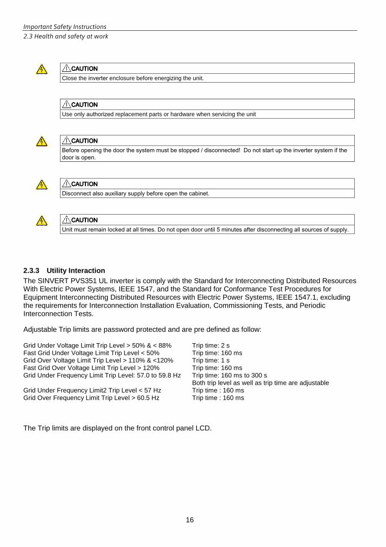
2.3.3 Utility Interaction The SINVERT PVS351 UL inverter is comply with the Standard for Interconnecting Distributed Resources With Electric Power Systems, IEEE 1547, and the Standard for Conformance Test Procedures for Equipment Interconnecting Distributed Resources with Electric Power Systems, IEEE 1547.1, excluding the requirements for Interconnection Installation Evaluation, Commissioning Tests, and Periodic Interconnection Tests. Adjustable Trip limits are password protected and are pre defined as follow: Grid Under Voltage Limit Trip Level > 50% & < 88% Trip time: 2 s Fast Grid Under Voltage Limit Trip Level < 50% Trip time: 160 ms Grid Over Voltage Limit Trip Level > 110% & <120% Trip time: 1 s Fast Grid Over Voltage Limit Trip Level > 120% Trip time: 160 ms Grid Under Frequency Limit Trip Level: 57.0 to 59.8 Hz Trip time: 160 ms to 300 s
Both trip level as well as trip time are adjustable Grid Under Frequency Limit2 Trip Level < 57 Hz Trip time : 160 ms Grid Over Frequency Limit Trip Level > 60.5 Hz Trip time : 160 ms The Trip limits are displayed on the front control panel LCD.
Important Safety Instructions
2.4 General safety instructions
17
2.4 General safety instructions
2.4.1 Proper usage To ensure the greatest possible degree of system safety, it is absolutely essential to use the product for its intended purpose. The SINVERT PVS351 UL and its variants are designed solely for the purpose of converting the energy generated by solar modules from a DC current into an AC current and of feeding this AC current into a low-voltage or medium-voltage grid. Compliance with all specifications regarding permissible conditions of use as outlined in this manual is essential. To satisfy this requirement, it is essential that these installation and operating instructions are read in full by the qualified personnel responsible for the system and that all instructions are followed. In addition, the conditions specified by the solar module manufacturer and grid operator must be fulfilled. The products may be modified only with the agreement of the manufacturer. It is not permissible to commission the system unless all requirements are satisfied in full. Any usage other than that described in this chapter is deemed to be improper usage. The manufacturer disclaims liability for any damage attributable to improper usage.
2.4.2 Use of approved equipment and components Always use the equipment and components described and approved by the manufacturer for the intended purpose. The manufacturer disclaims liability for any damage arising from the use of equipment or components which are not approved for the intended purpose.
2.4.3 Modifications to the product Modifications to the SINVERT PVS351 UL may be made only if these have been explicitly approved by the system manufacturer. The manufacturer shall not be liable for any damage arising from unapproved modifications to the SINVERT PVS351 UL.
WARNINGWARNINGWARNINGWARNING This device may only be used for the applications described in the technical description, and only in connection with devices or components from other manufacturers which have been approved or recommended by Siemens. This product can function correctly and reliably only if it is transported, stored, assembled, and installed correctly, and operated and maintained as recommended.

Description
3.1 Areas of application and use
18
3 Description
3.1 Areas of application and use The solar inverter is used in PV systems to convert the direct current from the PV generators into a three-phase current. This three-phase current is then fed into the connected power grid. The inverter design is optimized for the lowest possible losses and thus the greatest possible efficiency. Its EMC design makes it suitable for operation in areas susceptible to electromagnetic disturbance.
Figure 3-1 Overview of PV system - schematic representation
3.1.1 System integration The integrated DC and three-phase distribution makes the system compact and cheap to integrate. The system is provided with standardized interfaces so that it can be integrated into a control system or an existing installation.
Description
3.2 Properties and special features of the SINVERT PVS351 UL
19
3.2 Properties and special features of the SINVERT PVS351 UL • Standardized series product with UL1741 based NRTL mark • UL1998 certified software process • International standards: DIN VDE, IEC, CSA, EN • QS system is certified in accordance with DIN EN ISO 9001 • Optimized for high efficiency • Self-commutated, pulse-width-modulated (PWM) IGBT inverter • Compact design, very easy to install • Integrated DC connection including insulation monitor, contactors and semiconductor
fuses • Integrated AC connection with line monitor, line contactor and circuit breaker • Terminal compartment with separate panels for DC and AC terminal connections • Overvoltage surge protection on DC and AC sides • Built in anti-islanding protection to detect and isolate for grid failure under matched load
conditions • Positive or negative grounding through a fuse with fuse status monitoring circuit • Single phase open detection and isolation capability • Overvoltage / Undervoltage detection and isolation circuitry for abnormal grid conditions • Overfrequency / Underfrequency detection and isolation for abnormal grid conditions • Enclosed base plate with bushing for connecting cables • Cable propping bar • Bus communication via Industrial Ethernet for integration in operations management
systems • Operator control and monitoring elements integrated in cabinet door • Delivery on special pallet • Air inlet through ventilation grille at front, air exit at top • Heat dissipated by low-noise fan • All cabinet components can be recycled

Description
3.3 Design of the SINVERT PVS351 UL
20
3.3 Design of the SINVERT PVS351 UL 3 inputs with LV HRC fuses and DC contactors are provided at the PV field end. This combination can be used to disconnect the inverter from the PV field. The power unit comprises a standard power unit with IGBT-based three-phase bridge. A low-voltage transformer provides galvanic isolation and voltage adaption between the PV field and AC output. A contactor and circuit breaker are used to disconnect the unit from the grid. Overvoltage protection devices are installed at the AC and DC inputs. To increase efficiency and reduce light-load losses, up to four inverters can be interconnected in master-slave operation.
L1, L2, L
AC 480
60Hz
Control
Unit
1+, 1-
2+, 2-
3+, 3-
Touch
Panel
=
~
EMC-
Filter
EMC-
Filter
3
DC Input
Filter
AC Output
2
2
2
Figure 3-2 Block diagram of SINVERT PVS351 UL

Description
3.4 Inverter options
21
3.4 Inverter options
3.4.1 D40 PV field grounding negative pole The PVS351 UL by default comes with negative pole grounding. There is no need to order this option. For the latest information about the necessity for and type of grounding, please contact your module manufacturer! Some module manufacturers require either positive or negative grounding of the PV array when certain types of module are used. PV systems no longer constitute a DC IT system when their modules are grounded. For safety reasons, the PV system must be fenced in and designated as an electrical operating area. Access must be prohibited to all persons except qualified electricians.
3.4.2 D30 PV field grounding positive pole With the optional feature "Positive PV Field Grounding", the SINVERT inverters offer an ideal choice for manufacturers who require a positive module ground. Solar module manufacturers are launching a steadily increasing stream of new cell technologies or advances in the design of conventional modules. In addition to thin-film modules, these new technologies include back contact cells which require specific grounding conditions. For the latest information about the necessity for and type of grounding, please contact your module manufacturer! Some module manufacturers require either positive or negative grounding of the PV array when certain types of module are used. PV systems no longer constitute a DC IT system when their modules are grounded. For safety reasons, the PV system must be fenced in and designated as an electrical operating area. Access must be prohibited to all persons except qualified electricians.
3.4.3 D70: DC input voltage measurement Isolating amplifiers and down-circuit modules are used to acquire the voltages of the three DC inputs upstream of the contactors at the PV field input. The DC contactors for the DC inputs are closed by means of a software function only when the voltage has reached a suitable value.
3.4.4 M10: Symmetry monitoring With this option, the currents at the individual inverter inputs are measured and compared as a means of monitoring the connected PV field. The failure of a string is detected by the inverter which responds by issuing a fault message. No additional wiring is required in the PV field, as the measurement is performed in the control cabinet. The symmetry currents are set (normalized) once per inverter input according to the PV power connected. After a symmetry fault has been detected, the exact source of the fault is localized by measurement with a current clamp in the PV field. Current clamp resolution should be capable of better than 4 A. Symmetry faults on modules with rated currents of 4 A Impp and higher can be detected at high insolation levels. String faults cannot be detected on modules with 4A Impp and lower. This method has proven successful on MW installations for over ten years. Advantages as compared to current measurements directly in the PV field:
• The technology is resistant to lightening strikes • As field measurement systems are not used, they cannot fail • Instead of a high initial investment, faults can be detected inexpensively by means of a manual
detailed search at local level. Faults can often be repaired immediately.
Description
3.4 Inverter options
22
3.4.5 M20: Insulation measurement PV field This option involves the use of an insulation meter which monitors the system for low resistance to ground caused by insulation damage (e.g. to a cable). This monitoring function ensures the safety of personnel and is performed when the unit is not operating by periodically by momentarily opening the ground and measuring the insulation resistance.
3.4.6 M30: Monitoring system for weather station This option acquires the data of the external weather station (stand-alone product, currently not UL listed). The monitoring system is linked up via Profibus.
• 2x insolation sensors (module and direct/diffuse insolation) • 1x sensor for wind speed • 1x temperature sensor • 1x ambient temperature sensor • 1x rain sensor
3.4.7 P40: MV switchgear data Additional modules (currently not UL listed) are provided to acquire the following signals from the MV switchgear:
• Grounding On • Grounding Off • Circuit breaker Closed • Circuit breaker Open • Fuse tripped • Auxiliary switch fault • Meter pulse
The signals are displayed in the monitoring systems. The meter pulse (= pulse of an electricity meter) can be used to measure the energy feed into the grid.
3.4.8 P50: Additional signals from container Additional modules are provided to acquire the following signals from the container: Inputs:
• Container temperature • Inlet air temperature • Smoke alarm
Outputs:
• Horn control The smoke alarm signal is read in and transferred to the monitoring systems. The signal is also connected to an output so that it can be used, for example, to control a horn. The container temperature and inlet air temperature signals can be used to drive the inverter cabinet fans in energy-saving mode.
Description
3.4 Inverter options
23
3.4.9 S10 : Cabinet heating To prevent condensation, heating elements are integrated in the inverter. These are controlled by thermostats.
3.4.10 S30: Auxiliary power supply The inverter cabinet can be supplied from an external auxiliary power supply This auxiliary supply provides power to a number of internal auxiliary components (fans, contactors, DC/DC converters, control). The connection (3 phases and PE 480VAC +/-10%) is made by means of an external feeder cable to terminals provided in the cabinet. The default control power supply is configured from the inverter AC output terminals, where the 480 VAC grid is connected. In case of auxiliary power supply from an on-site external generator, the customer can change the jumpers on Terminal Block X240 from 1-2 to 2-3, 4-5 to 5-6, and 7-8 to 8-9. The auxiliary power supply shall provide three-phase (with neutral) 480 VAC and no less than 15 A line current capacity. This auxiliary power supply is also directly routed to a terminal block X240, which is over-current protected by 15 A fuses and can be used for field external load. In case the external load power is required when the unit is running, an additional 15 A line current capacity shall also be provided from the auxiliary power supply.
3.4.11 S40: Output for external Load Two fuse-protected load outputs for supplying external loads (e.g. for tracker control) are provided.
• One output with 3 phases/PE (480VAC/15A)
The two external load power ports are fuse protected and are generally only available when the inverter is not running. These external load power ports are defined as:
• Port X208, three-phase, 480 VAC, 15 A; • Port X209, single-phase, 230 VAC, 10A.
Storage and transport
4.1 Packaging, dispatch and delivery
24
4 Storage and transport The following chapter contains detailed information about packaging, dispatch, delivery, storage and transportation. Always read and follow the instructions given in this installation manual. Observe the relevant safety notices at all times. Make sure that the conditions specified for storage and transportation are fulfilled.
4.1 Packaging, dispatch and delivery Further information about the transport packaging used, dispatch of the inverter by Siemens and the measures to be taken following delivery of the unit is given below.
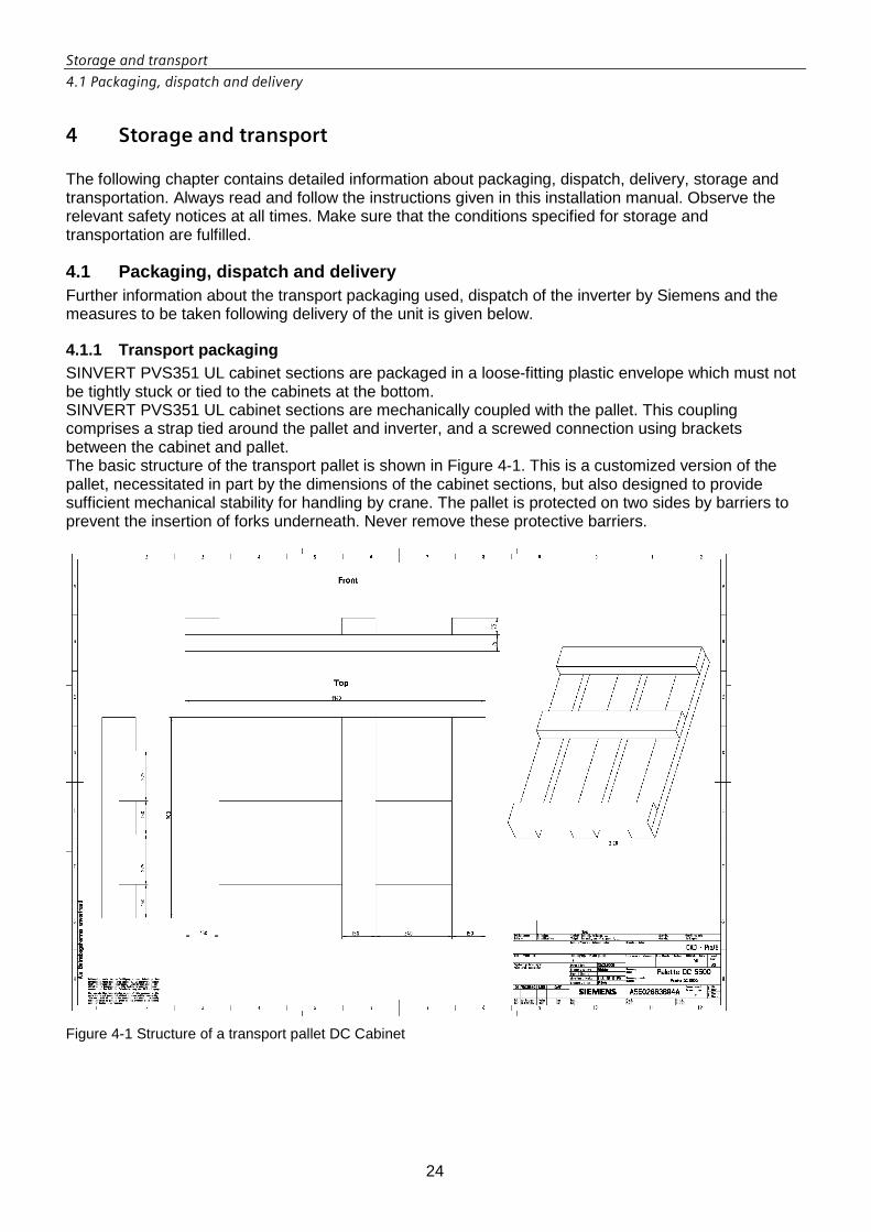
4.1.1 Transport packaging SINVERT PVS351 UL cabinet sections are packaged in a loose-fitting plastic envelope which must not be tightly stuck or tied to the cabinets at the bottom. SINVERT PVS351 UL cabinet sections are mechanically coupled with the pallet. This coupling comprises a strap tied around the pallet and inverter, and a screwed connection using brackets between the cabinet and pallet. The basic structure of the transport pallet is shown in Figure 4-1. This is a customized version of the pallet, necessitated in part by the dimensions of the cabinet sections, but also designed to provide sufficient mechanical stability for handling by crane. The pallet is protected on two sides by barriers to prevent the insertion of forks underneath. Never remove these protective barriers.
Figure 4-1 Structure of a transport pallet DC Cabinet

Storage and transport
4.1 Packaging, dispatch and delivery
25
Figure 4-2 Structure of a transport pallet AC Cabinet

Storage and transport
4.1 Packaging, dispatch and delivery
26
4.1.2 Center of gravity marking on inverter The weight mass of the cabinet sections is distributed eccentrically and asymmetrically on both the front and side faces. The weight distribution is indicated directly on each cabinet section of the inverter (see Figure 4-2) by the center of gravity marking in accordance with ISO 780/symbol 7.
Figure 4-3 Center of gravity marking on inverter
The SINVERT PVS351 UL inverter must never be tipped. Symbol 3 of ISO 780 specifies the transport position (see Figure 4-3). Always take note of the center of gravity marking and the specified transport position.
Figure 4-4 Transport position of the SINVERT PVS351 UL

Storage and transport
0
27
4.1.3 Dispatch and delivery The PVS351 UL is delivered in two separate units. Each cabinet section is transported on a special pallet. The consignments are checked by Siemens prior to dispatch to ensure that they are correctly packaged and free of damage.
4.1.4 Checking the consignment Please check that the consignment is complete against the accompanying dispatch documentation. If any items are missing from the consignment, please notify the relevant contact person immediately. SINVERT PVS351 UL inverters are shipped with transport monitoring sensors (see Figure 4-4). The permissible mechanical ambient conditions for transportation can be found in Chapter 11. The sensors are capable of verifying whether the units have been improperly handled. Please check both the shock and the tilt sensor when the consignment is delivered. The indicators are colored red if the consignment has been handled incorrectly.
Figure 4-5 Shock and tilt sensors
If the sensors have been removed, it must also be assumed that the consignment has been incorrectly handled. In these instances, note on the consignment papers that the sensors have been activated and contact the relevant contact person at Siemens immediately. You are expressly forbidden from commissioning the unit until the situation has been clarified with Siemens.

Storage and transport
4.2 Possible transportation methods
28
4.2 Possible transportation methods The methods described below are the only permitted methods for transporting the SINVERT PVS351 UL. No other method of transport is permitted. Siemens shall not accept liability for any personal injuries or property damage resulting from the transportation of the product by an improper method. In addition to the safety notices applicable to specific transport methods, the general safety instructions must also be noted and followed.
4.2.1 General safety instructions Regardless of the method of transport applied, the general safety instructions must always be followed. These mainly refer to the mechanical connection between the pallet and the inverter cabinet section, to the mechanical connection between individual inverters and to the risk of tipping.
Figure 4-6 Transport packaging – Mechanical connection with the transport pallet
Never transport the pallet with the inverter cabinet section without a secure mechanical connection between the pallet and inverter (see Figure 4-5). The mechanical connection comprises a strap and a screwed connection between the cabinet base and pallet. Before the package is moved, the screwed connection and strap must be checked to ensure they are secure. Please also note the safety notice (below) regarding the risk of tipping if the pallet and cabinet are not mechanically connected.
Storage and transport
4.2 Possible transportation methods
29
WARNINGWARNINGWARNINGWARNING
Risk to life! Tipping! Load can fall off pallet!Risk to life! Tipping! Load can fall off pallet!Risk to life! Tipping! Load can fall off pallet!Risk to life! Tipping! Load can fall off pallet!
The cabinet may be transported only if it is securely mechanically coupled with the pallet (strap and screwed connection). If the load is not securely coupled, it can tip or fall off the pallet. In this case, the high weight mass of the cabinets can cause serious injuries, death and substantial property damage.
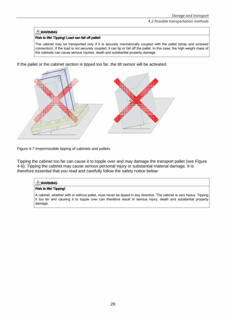
If the pallet or the cabinet section is tipped too far, the tilt sensor will be activated.
Figure 4-7 Impermissible tipping of cabinets and pallets
Tipping the cabinet too far can cause it to topple over and may damage the transport pallet (see Figure 4-6). Tipping the cabinet may cause serious personal injury or substantial material damage. It is therefore essential that you read and carefully follow the safety notice below:
WARNINGWARNINGWARNINGWARNING
Risk to life! Tipping!Risk to life! Tipping!Risk to life! Tipping!Risk to life! Tipping!
A cabinet, whether with or without pallet, must never be tipped in any direction. The cabinet is very heavy. Tipping it too far and causing it to topple over can therefore result in serious injury, death and substantial property damage.
Storage and transport
4.2 Possible transportation methods
30
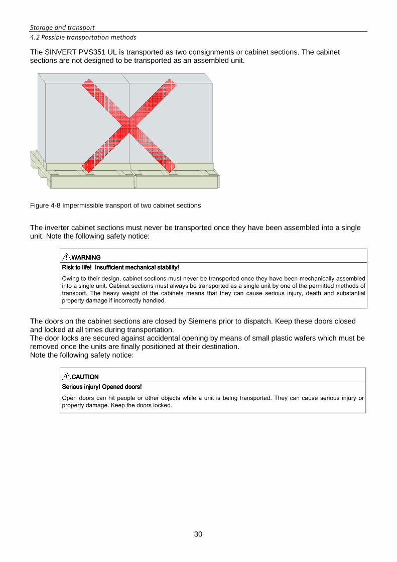
The SINVERT PVS351 UL is transported as two consignments or cabinet sections. The cabinet sections are not designed to be transported as an assembled unit.
Figure 4-8 Impermissible transport of two cabinet sections
The inverter cabinet sections must never be transported once they have been assembled into a single unit. Note the following safety notice:
WARNINGWARNINGWARNINGWARNING
Risk to life! Insufficient mechanical stability!Risk to life! Insufficient mechanical stability!Risk to life! Insufficient mechanical stability!Risk to life! Insufficient mechanical stability!
Owing to their design, cabinet sections must never be transported once they have been mechanically assembled into a single unit. Cabinet sections must always be transported as a single unit by one of the permitted methods of transport. The heavy weight of the cabinets means that they can cause serious injury, death and substantial property damage if incorrectly handled.
The doors on the cabinet sections are closed by Siemens prior to dispatch. Keep these doors closed and locked at all times during transportation. The door locks are secured against accidental opening by means of small plastic wafers which must be removed once the units are finally positioned at their destination. Note the following safety notice:
CAUTIONCAUTIONCAUTIONCAUTION
Serious injury! Opened doors!Serious injury! Opened doors!Serious injury! Opened doors!Serious injury! Opened doors!
Open doors can hit people or other objects while a unit is being transported. They can cause serious injury or property damage. Keep the doors locked.

Storage and transport
4.2 Possible transportation methods
31
4.2.2 Transport by elevating-platform truck The driver of the industrial truck must always ensure that the equipment required to move the load is in good working order and that high standards of operational safety are fulfilled. Loads must always be transported in compliance with all relevant health and safety regulations as well as the instructions in this installation and operating manual. Always use an elevating-platform truck which is approved to carry the weight of the relevant cabinet section. Forks can be inserted under the pallet on two sides. Barriers are fitted on the other two sides. These must never be removed. There is a risk the unit will tip if forks are inserted under it on the wrong side.
Figure 4-9 Transport methods – transport by elevating-platform truck
Owing to the high and eccentric center of gravity of the cabinet sections, there is a risk that they will topple over if incorrectly handled.
WARNINGWARNINGWARNINGWARNING
Risk to life! Tipping!Risk to life! Tipping!Risk to life! Tipping!Risk to life! Tipping!
A cabinet, whether with or without pallet, must never be tipped. The cabinet is very heavy. Tipping it too far and causing it to topple over can therefore result in serious injury, death and substantial property damage.

Storage and transport
4.2 Possible transportation methods
32
4.2.3 Transportation by fork-lift truck The driver of the industrial truck must always ensure that the equipment required to move the load is in good working order and that high standards of operational safety are fulfilled. Loads must always be transported in compliance with all relevant health and safety regulations as well as the instructions in this installation and operating manual.
Always use an fork-lift truck which is approved to carry the weight of the relevant cabinet section. Figure 4-9 shows the basic method for transportation by fork-lift truck.
Figure 4-10 Transport methods – transport by fork-lift truck
Forks can be inserted under the pallet on only two sides. Barriers are fitted on the other two sides. These must never be removed. There is a risk the unit will tip if forks are inserted under it on the wrong side (see Figure 4-10).
WARNINGWARNINGWARNINGWARNING
Risk to life! Tipping!Risk to life! Tipping!Risk to life! Tipping!Risk to life! Tipping!
A cabinet, whether with or without pallet, must never be tipped. The cabinet is very heavy. Tipping it too far and causing it to topple over can therefore result in serious injury, death and substantial property damage.

Storage and transport
4.2 Possible transportation methods
33
4.2.4 Transport by crane There are two possible methods of transporting the cabinet section by crane:
• Transport with an adjustable H beam • Transport with a frame specially designed for the task
These different methods are described in detail below. Owing to the design of the cabinets, it is expressly prohibited to use the crane transport methods listed immediately below to move the SINVERT PVS351 UL:
• Transport on crane eyelets • Transport on steel lifting elements • Any methods not expressly approved in this description
The crane driver must always ensure that the crane and the equipment required to move the load are in good working order and that high standards of operational safety are fulfilled. Loads must always be transported in compliance with all relevant health and safety regulations as well as the instructions in this installation and operating manual.
WARNINGWARNINGWARNINGWARNING
Risk to life! Failure to use approRisk to life! Failure to use approRisk to life! Failure to use approRisk to life! Failure to use appropriate transportation equipment!priate transportation equipment!priate transportation equipment!priate transportation equipment!
The equipment used must be designed to carry the load to be transported. It must be in good working order and correspond to one of the approved methods specified in this manual. When equipment of a type not approved is used to transport loads, they can drop or topple over, causing serious injury, death or substantial property damage.
Please ensure compliance with all safety requirements relating to the transportation of suspended loads:
WARNINGWARNINGWARNINGWARNING
Risk to life! SuspendedRisk to life! SuspendedRisk to life! SuspendedRisk to life! Suspended load! load! load! load!
Never stand under a suspended load. There is a risk of serious injury, death or substantial property damage if the load drops off the crane.
Always take into account the high center of gravity and asymmetric load distribution as well as the instructions relating to attachment of the load.
WARNINGWARNINGWARNINGWARNING
Risk to life! Asymmetric load distribution!Risk to life! Asymmetric load distribution!Risk to life! Asymmetric load distribution!Risk to life! Asymmetric load distribution!
It is essential to note the center of gravity marking and the asymmetric load distribution when attaching the load. There is a risk of serious injury, death or substantial property damage if the load drops off the crane.

Storage and transport
4.2 Possible transportation methods
34
Permissible methods of transport by crane There are basically two permissible methods of transporting the cabinets by crane:
• Transport with an H beam (see Figure 4-10) • Transport with a frame structure (see Figure 4-11)
Figure 4-11 Transport methods – crane transport using an H beam
The cabinets are not designed to be transported by any other method and other methods are not therefore permitted. Should you choose a method of crane transport which is not expressly approved in this document, Siemens shall not accept liability for the consequential damage. Whether a load is transported by crane on an H beam or a specially designed frame structure, it is always essential that the inverter is mechanically coupled to the pallet. The crane ropes are placed under the load at a marked position in parallel to the side wall. They are then brought up in parallel to and at an appropriate distance from the straps, from where they are threaded through a frame structure or attached to the H beam (see Figure 4-12).

Storage and transport
4.2 Possible transportation methods
35
Figure 4-12 Transport methods – crane transport using a frame
Always pay attention to the eccentric load distribution, the transport position and the center of gravity marking on the inverter. Failure to do so may result in the load dropping or toppling over.
Figure 4-13 Transport methods – straps and positioning of ropes
WARNINGWARNINGWARNINGWARNING
Risk to life! Asymmetric load distribution!Risk to life! Asymmetric load distribution!Risk to life! Asymmetric load distribution!Risk to life! Asymmetric load distribution!
It is essential to note the center of gravity marking and the asymmetric load distribution when attaching the load. There is a risk of serious injury, death or substantial property damage if the load drops off the crane.

Storage and transport
4.2 Possible transportation methods
36
Prohibited methods of transport by crane An overview of transport methods which are expressly prohibited by the manufacturer are given below:
• Use of crane eyelets (Figure 4-13) • Use of steel lifting elements (Figure 4-14) • Attachment of ropes along vertical sides of load (Figure 4-15)
Figure 4-14 Transport methods – prohibited use of crane eyelets
Please note that other methods apart from those mentioned above are also prohibited if they are not expressly approved by Siemens as a permissible method of transport.

Storage and transport
4.2 Possible transportation methods
37
Figure 4-15 Transport methods – prohibited use of steel lifting elements
The combination of pallet and converter is not designed to withstand the mechanical stresses of transportation on crane eyelets or steel lifting elements. You must not transport the inverter (whether with or without transport pallet) on steel lifting elements or crane eyelets. It is essential that you note and comply with the following safety notice:
WARNINGWARNINGWARNINGWARNING
Risk to life! Prohibited use of crane eyelets and steel lifting elements!Risk to life! Prohibited use of crane eyelets and steel lifting elements!Risk to life! Prohibited use of crane eyelets and steel lifting elements!Risk to life! Prohibited use of crane eyelets and steel lifting elements!
The inverter cabinets are not designed for transportation by crane on eyelets or steel lifting elements. It is absolutely prohibited to transport the inverters on crane eyelets or steel lifting elements. If excessive mechanical stress causes the load to fall off the crane, there is a risk of serious injury, death or substantial property damage.

Storage and transport
4.2 Possible transportation methods
38
Figure 4-16 Transport methods – prohibited attachment of ropes along vertical sides of load
Likewise prohibited is the attachment of ropes along the vertical sides of the load, irrespective of whether this involves a frame structure, an H beam or direct attachment from a hook (see Figure 4-15). There is an increased risk of toppling or dropping if the load is suspended from ropes attached along the vertical sides.
WARNINGWARNINGWARNINGWARNING
Risk to life! Prohibited attachment of ropes alonRisk to life! Prohibited attachment of ropes alonRisk to life! Prohibited attachment of ropes alonRisk to life! Prohibited attachment of ropes along vertical sides of load!g vertical sides of load!g vertical sides of load!g vertical sides of load!
The cabinets are not designed to be transported by crane from ropes attached along the vertical sides of the load. This method of transport is expressly prohibited. If excessive mechanical stress causes the load to fall off or topple over, there is a risk of serious injury, death or substantial property damage.

Storage and transport
4.2 Possible transportation methods
39
4.2.5 Transport and alignment of cabinets in electr ical operating areas The cabinets are attached to the pallet by means of transport locks (upward-facing screws). To lift the cabinets off the pallet, you first need to undo the screw nuts. To slide the cabinets off the pallet, you need to push the screws out downwards far enough (e.g. using a hammer and a thick nail), so that the surface of the pallet becomes flat. All cabinets can be moved on rollers placed under the cabinet frame. As rollers, you should use solid metal rods with a length of 20 cm and a diameter of 2 cm.
Figure 4-17 Moving the cabinet off the standard pallet
Use a crowbar to lift the cabinet so that you can place the rollers under the frame. If you want to change the rolling direction, you must lift the cabinet again, turn the rollers by 90° and place them under t he frame again. You may need to strengthen the floor (with metal sheets) before you move the cabinets over it. Make sure that the metal sheets are placed such that you will be able to remove them again once the inverters have been installed. In order to move or roll the cabinet off the pallet, you will need a solid metal bar or a strong pipe of 100 cm in length and 6 cm in diameter. Then proceed as follows:
• Adjust the pallet so that it is level with the adjacent surface (e.g. floor of the plant room). • Cover the gap between the pallet and floor with a metal sheet (5 to 10 cm) so that the rollers do
not get caught in the gap. • Place a roller on the metal sheet and under the cabinet frame. • Place a thick roller under the cabinet at a position where there are no cross-planks in the pallet. • With the assistance of installation personnel, push the cabinet off the pallet. • As the cabinet moves forward, place more rollers underneath.

Storage and transport
4.3 Storage
40
NOTENOTENOTENOTE Use thick-walled steel rods. Round steel bars, round hardwood timbers or steel rollers enclosed in concrete are also suitable for the purpose. The bars must have a minimum diameter of 6 cm. The bars must be at least 1/5 longer than the transportation unit / cabinet.
4.3 Storage It is absolutely essential that the inverter units are stored in compliance with the storage conditions specified in Chapter 11. In the event of ingress of dirt, pollutants or liquid into the equipment, formation of condensation, damage or any other failures to comply with the prescribed storage conditions, the equipment must not be commissioned until the correct remedial procedure has been discussed with and approved by Siemens AG. The devices must be stored such that they are protected against the ingress of sand or dust. In the case of noncompliance with the above, Siemens will not accept liability for damage arising from unauthorized commissioning.
WARNINGWARNINGWARNINGWARNING
Risk to life! Unauthorized commissioning!Risk to life! Unauthorized commissioning!Risk to life! Unauthorized commissioning!Risk to life! Unauthorized commissioning!
Cabinets which have been stored in conditions that do not meet the prescribed standard must not be commissioned. Failure to comply with storage standards may result in electric shock, other serious injury or substantial property damage.

Site of installation
5.1 General requirements
41
5 Site of installation The site of installation must comply with certain requirements relating to environmental conditions, construction and layout of operating areas, connections to be provided, noise control, fire protection, EMC and ventilation. Detailed information about the requirements of the installation site can be found below.
5.1 General requirements A room which is deemed suitable to house a SINVERT PVS351 UL must comply with certain general requirements in addition to the applicable environmental conditions. These are described in detail below.
Foundation The inverter must be erected on a dry, level and non-combustible foundation. This foundation must be constructed such that it can withstand the static and dynamic stresses produced by the inverter.
Connections The connections described below must be provided at the site of installation so that the SINVERT PVS351 UL can be installed easily and correctly.
Electromagnetic compatibility (EMC) The inverter has been tested for electromagnetic immunity in accordance with the IEEE Standard C37.90.2-1995 IEEE Standard for Withstand Capability of Relay Systems to Radiated Electromagnetic Interference from Transceivers per IEEE-1547 - IEEE Standard For Interconnecting Distributed Resources With Electric Power Systems. The SINVERT PVS351 UL is thus designed for use in industrial environments. It is not designed for use in residential environments. Siemens shall not accept liability for any consequential damage if the device is installed in a residential environment.
Degree of pollution Suitable measures must be taken to ensure that degree of pollution 2 is not exceeded inside the inverter cabinets.

Site of installation
5.1 General requirements
42
5.1.1 Electrical operating areas In addition to the environmental conditions for operation and the general requirements of sites of installation, electrical operating areas must also comply with further special requirements. The SINVERT PVS351 UL must be installed in a locked electrical operating area. IEC 60050-826:2004 defines a locked electrical operating area as a "room or space which is used exclusively for the operation of electrical equipment and which is kept locked". The lock may be opened only by authorized persons. Access is restricted to persons with appropriate electrical qualification. Compliance with the requirements of DIN VDE 0100-731 (Erection of power installations with rated voltages below 1000 V – Electrical locations and locked electrical locations) is particularly important. A number of key requirements are listed in brief below. For a detailed description of all requirements, please refer to IEC 60050-826:2004, IEC 60364-7-729:2007and DIN VDE 0100-731. Compliance with all these requirements is mandatory.
WARNINGWARNINGWARNINGWARNING
Risk to life! Access by unauthorized persons!Risk to life! Access by unauthorized persons!Risk to life! Access by unauthorized persons!Risk to life! Access by unauthorized persons!
If the requirements pertaining to locked electrical operating areas are not fulfilled, unauthorized persons might gain access to the inverter. Lack of knowledge in the safe handling of electrical installations by such persons could result in death, serious injury and substantial property damage.
Barriers and labeling DIN VDE 0100-731 stipulates that electrical and locked electrical operating areas must be segregated from other areas by barriers of at least 1800 mm in height. Where the barriers are formed by grating, the maximum permissible mesh size is 40 mm. An adequate number of warning notices must be displayed at access points.
Walkways, doors, windows Doors The following requirements apply to the doors of locked electrical operating areas:
• Access only through lockable doors or covers • Doors must open outwards • Door locks must prevent access to unauthorized persons, but allow exit from the area
Windows Windows must be locked to prevent persons from entering in cases where the locked electrical operating areas are not located in enclosed premises or on a secure site. Escape route/walkways DIN VDE 0100-731 stipulates that an escape route must not exceed 40 m in length. DIN VDE 0100-729 specifies that walkways of over 20 m in length must be accessible from both sides; this is recommended for walkways of more than 6 m in length. The inverter is designed with mechanical degree of protection IP20, the door opening angle is 180°. The minimum clearance between the wall and inverter is 1000 mm (see Figure 5-1/right). When inverters are installed front to front, it is expected that open doors will restrict space on one side only. With this layout as well, a clearance of at least 1000 mm must be provided between inverters installed front to front (see Figure 5-1/left) to allow for the 160° door opening angle. Doors may be opened onl y on one side of the inverter line-up, but not on opposite sides at the same time.

Site of installation
5.1 General requirements
43
1000
1000
Figure 5-1 Widths of walkway
Compliance with the specified walkway widths and escape route lengths is essential. It may be necessary to comply with further requirements stipulated by local regulations. Please also take the following safety notice into consideration:
WARNINGWARNINGWARNINGWARNING
Risk to life! Walkways too narrowRisk to life! Walkways too narrowRisk to life! Walkways too narrowRisk to life! Walkways too narrow //// escape routes too long!escape routes too long!escape routes too long!escape routes too long!
Walkways which are too narrow or escape routes which are too long can hinder or prevent the escape of people in emergency situations. Death and serious injury can result.

Site of installation
5.2 Ventilation
44
5.2 Ventilation The following requirements must be fulfilled in order to ensure adequate ventilation of the inverter cabinets:
• The ambient temperatures must remain within the specified tolerance range • The required quantity of air flow must be provided • The heated exit air must be drawn away from the unit so that the maximum permissible ambient
temperature is not exceeded • It is essential to prevent thermal short circuits • The supply air must comply with the technical specifications (Chapter 11) (air quality,
contamination, moisture content) Air enters the inverter via the vents in the doors and exits via the grille on top of the cabinet.
Figure 5-2 Ventilation - minimum clearance at top for a container installaton (removing the cabinet roof)

Site of installation
5.3 Grounding and lightning protection
45
5.3 Grounding and lightning protection Lightning protection and grounding systems must be implemented in accordance with IEC 62305.
5.3.1 Grounding concept In order to dissipate lightning current into the ground (high frequency behavior) and thus reduce hazardous overvoltages, the form and dimensions of the grounding system are key criteria. A low ground resistance (less than 10 Ω, measured at low frequency) is generally recommended by IEC 62305-3. In the case of ground-mounted PV installations, the individual grounding systems, e.g. of the plant building and PV module field, must be intermeshed. This produces a large "equipotential area" which significantly reduces the voltage stress on the electrical connecting cables between the PV module field and the plant building in the event of a lightning strike. A mesh size of 20 m x 20 m up to 40 m x 40 m has proven effective onlarge-scale PV installations.
5.3.2 Lightning protection concept Suitable external lightning protection measures must be taken to ensure that direct lightning strikes are intercepted and dissipated to a grounding system in such a way that no currents can impact on building installations and the PV power supply system housed in them. Internal lightning protection measures must be devised to prevent the effects of lightning strikes and differences in potential on and inside the building. The arrangement and positioning of interception devices can be determined by three methods:
• Lightning rod method • Mesh method • Protection angle method
The external lightning protection system comprises an interception system, an arrester and a grounding system. If the container has a metal coping around its circumference, small lightning spikes are fitted to the corners of the container roof as interceptors. To implement a lightning protection system compliant with protection class III, an arrester must be installed at intervals of 15 m. The arresters are attached to the metal coping and lead then in a straight line to the grounding system. The main equipotential bonding busbar of the container is also connected to the grounding system.

Installation
6.1 Mechanical installation
46
6 Installation You will find instructions and tips on the correct procedure for installing the SINVERT PVS351 UL mechanically and electrically. Always take note of the safety notices in the relevant chapters. Always comply with the relevant local rules and regulations which apply at the site of installation.
6.1 Mechanical installation
6.1.1 General The devices must be installed and cooled in accordance with the guidelines in this document. Protect the inverters against impermissible stresses and loading.
6.1.2 Requirements of the site of installation The operating areas must be dry and free of dust. The air supplied must not contain any electrically conductive gas, vapors, or dust, which could impair operation.
6.1.3 Unpacking Make sure that the entire consignment is undamaged. The packaging material must be disposed of in accordance with the applicable country-specific guidelines and rules.
6.1.4 Tools required • Torque wrench 20 to 100 Nm • Ratchet screwdriver with extension • Socket wrench insert 12 mm, 13 mm, 17 mm, 18 mm • Open jaw wrenches 12 mm, 13 mm, 17 mm, 18 mm (metric screws) • Screwdriver slotted 1 mm, 2 mm, 3 mm • Torx screwdriver T20
6.1.5 Safety information on bolting the cabinet sec tions together
CAUTIONCAUTIONCAUTIONCAUTION MechanicalMechanicalMechanicalMechanical damagedamagedamagedamage Stresses occurring during transport can exert mechanical pressure on the components. This can result in property damage.
• Line the cabinets up precisely with each other in order to avoid shearing forces when the base units are bolted together.
• Make sure that the ground on which the inverter is to be installed is completely level and flat.

Installation
6.1 Mechanical installation
47
6.1.6 Bolting the cabinet sections together Position the cabinets in such a way that both frames line up exactly and the threaded bolts can be inserted through the holes on both sections. Use the threaded bolts from the accessories pack. Bolt the two cabinets together at the accessible points on the frame and tighten each screwed connection to a torque of 20 Nm. To make an optimum screwed connection between the cabinets, the cover over the AC capacitors should be removed, as well as the covers and protective grilles on the inverter.
Figure 6-1 Bolting the cabinet sections together
6.1.7 Mechanical connection to the floor To fix the cabinet on the front side use the holes at the front bottom frame and the fixing brackets on the transport pallet. For fixing on the back side there are two possibilities: - If there is a distance between cabinet and container wall the same fixing method can be used. - Otherwise use the across transport holes on the back side in combination with a retaining dowel as follow. Dimensions are in mm.
Note the floor template for pre-installation of the screw connections to the foundation.

Installation
6.1 Mechanical installation
48
6.1.8 Remove the transport fixing of the transforme r The transformer in the AC cabinet is fixed against vibration during transport by two fixing bolts. Before electrical connection the fixings shall be removed as follow: 1. Open the 3 screws of the plate holding the heating module.
Figure 6-2 Cover plate for transport fixing
2. Lift the cover plate to have access to the transformer fixings.
Figure 6-3 Cover plate opened
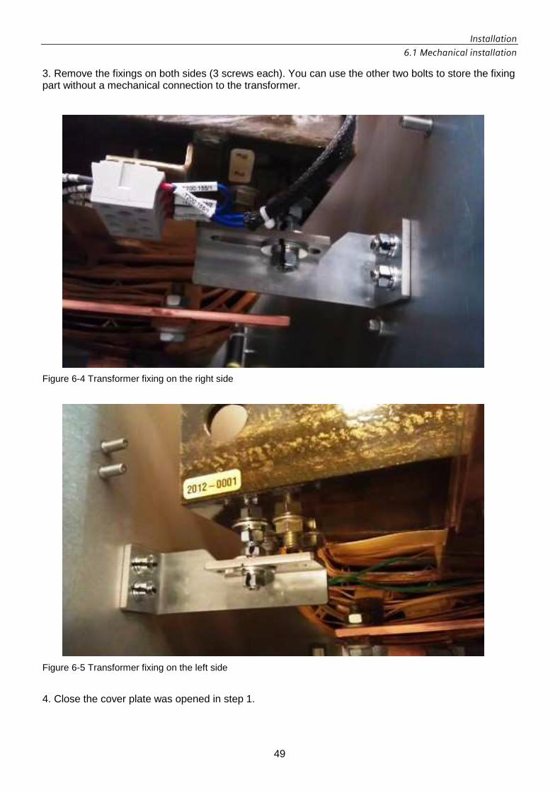
Installation
6.1 Mechanical installation
49
3. Remove the fixings on both sides (3 screws each). You can use the other two bolts to store the fixing part without a mechanical connection to the transformer.
Figure 6-4 Transformer fixing on the right side
Figure 6-5 Transformer fixing on the left side
4. Close the cover plate was opened in step 1.

Installation
1.1
50
6.2 Electrical installation
6.2.1 Observe the five safety rules For the sake of your own personal safety and to avoid the risk of property damage, follow the safety notices below. In particular pay attention to the safety-related instructions on the product itself and always read the section headed "Safety Instructions" in every document.
DANGERDANGERDANGERDANGER Danger due to high voltageDanger due to high voltageDanger due to high voltageDanger due to high voltagessss High voltages cause death or serious injury if safety instructions and notices are not observed or if the equipment is handled incorrectly. Potentially fatal voltages occur when this equipment is in operation which can remain present even after the inverter is switched off. Ensure that all work on this equipment is undertaken by appropriately qualified and trained personnel. Keep to the five safety rules at all times and at every stage of work: The five safety rules:The five safety rules:The five safety rules:The five safety rules: 1. Isolate from power supply1. Isolate from power supply1. Isolate from power supply1. Isolate from power supply 2. Secu2. Secu2. Secu2. Secure against reconnectionre against reconnectionre against reconnectionre against reconnection 3. Make sure that the equipment is de3. Make sure that the equipment is de3. Make sure that the equipment is de3. Make sure that the equipment is de----energizedenergizedenergizedenergized 4. Ground and short4. Ground and short4. Ground and short4. Ground and short 5. Cover or place guards around adjacent live parts5. Cover or place guards around adjacent live parts5. Cover or place guards around adjacent live parts5. Cover or place guards around adjacent live parts

Installation
6.2 Electrical installation
51
6.2.2 External cabling The following cable connections must be installed:
Table 6-1 External cable connections
Cable connection Cross-section Screw / connection type
DC connection (3x2 cables) Use 75º C copper = 700 kcmil 90º C copper = 600 kcmil M12
AC connection (L1, L2, L3) Use 75º C copper = 1000 kcmil 90º C copper = 750 kcmil M12
DC link (for master/slave) (2x2 cables) Use 75º C copper = 700 kcmil (3No.s) 90º C copper = 600 kcmil 9 (3No.s) M12
Grounding 35 mm2 / AWG 2 M10
AC auxiliary power supply (optional) 4 mm2 / AWG 11 clamp
Weather station (optional) 4 mm2 / AWG 11 clamp
Master-slave communication Patch cable connector
Profibus Profibus cable connector
Communication Patch cable connector
Table 6-2 Torques for conducting screw connections
CAUTIONCAUTIONCAUTIONCAUTION To mount the connection terminals use screws and torque are specified above. The terminal connector shall be readily accessible for tightening before and after installation of conductors.
Screw Torque AC outputs 60 Nm / 531.05 Lb-in DC inputs 60 Nm / 531.05 Lb-in Grounding 60 Nm / 531.05 Lb-in
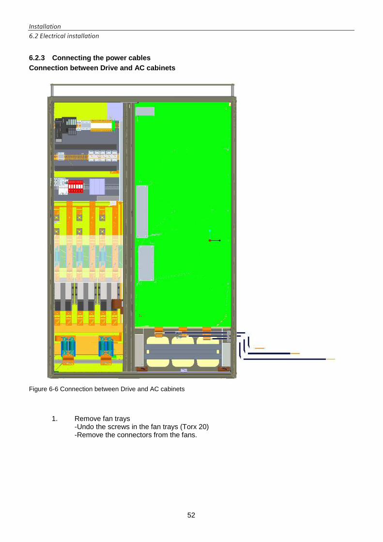
Installation
6.2 Electrical installation
52
6.2.3 Connecting the power cables Connection between Drive and AC cabinets
Figure 6-6 Connection between Drive and AC cabinets
1. Remove fan trays
-Undo the screws in the fan trays (Torx 20) -Remove the connectors from the fans.
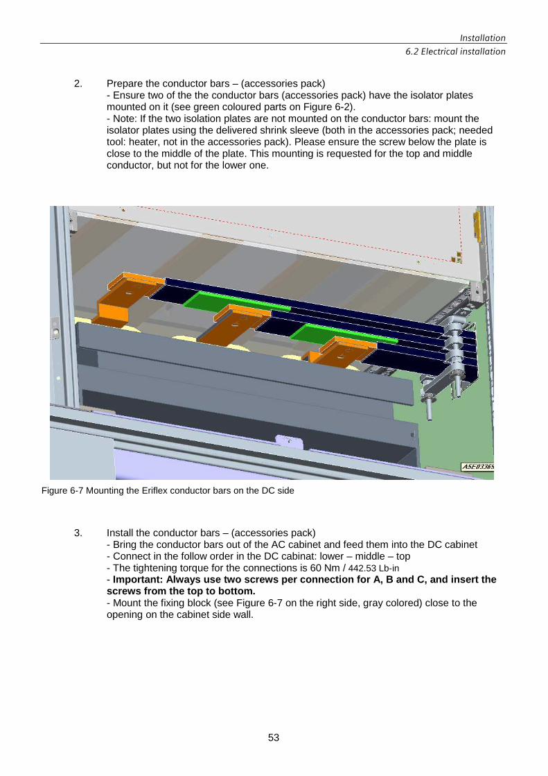
Installation
6.2 Electrical installation
53
2. Prepare the conductor bars – (accessories pack)
- Ensure two of the the conductor bars (accessories pack) have the isolator plates mounted on it (see green coloured parts on Figure 6-2). - Note: If the two isolation plates are not mounted on the conductor bars: mount the isolator plates using the delivered shrink sleeve (both in the accessories pack; needed tool: heater, not in the accessories pack). Please ensure the screw below the plate is close to the middle of the plate. This mounting is requested for the top and middle conductor, but not for the lower one.
Figure 6-7 Mounting the Eriflex conductor bars on the DC side
3. Install the conductor bars – (accessories pack) - Bring the conductor bars out of the AC cabinet and feed them into the DC cabinet - Connect in the follow order in the DC cabinat: lower – middle – top - The tightening torque for the connections is 60 Nm / 442.53 Lb-in - Important: Always use two screws per connection for A, B and C, and insert the screws from the top to bottom. - Mount the fixing block (see Figure 6-7 on the right side, gray colored) close to the opening on the cabinet side wall.

Installation
6.2 Electrical installation
54
Main AC grid Connect up the power cables to L1, L2 and L3 as illustrated in Figure 6-8. Make sure that you provide strain relief for the power cables. Important – the cabinet must be grounded! Use a ground strap on the strain relief!
Figure 6-8 AC connection

Installation
6.2 Electrical installation
55
AC auxiliary power supply A jumper connection is provided between terminal block X240 and the external voltage supply as standard (jumper in terminal 2+3; 5+6; 8+9). Connect up the external voltage supply as follows: L1 Terminal 3 L2 Terminal 6 L3 Terminal 9 N To N connection terminal PE To grounding terminal If the auxiliary power supply is to be supplied internally, the jumper connection for terminal block X240 must be made as follows: Jumper in terminal 1+2; 4+5; and 7+8; Connection of User Options User options like Weather Station or Smoke alarm can be connected at the AC Output area. Use the cable tray left of the AC inputs up to the right bottom clamps in the left side AC cabinet.
CAUTIONCAUTIONCAUTIONCAUTION The control signal cables must be separated from the AC power cable.
AC circuit breaker settings Ir = 500A tr = 2,5 sec
Ii = 240A x10

Installation
6.2 Electrical installation
56
DC input Connect up the power cables to DC1, DC2 and DC3. Make sure that you provide strain relief for the power cables. Important – the cabinet must be grounded! Use a ground strap on the strain relief!
Figure 6-9 DC connection

Installation
6.2 Electrical installation
57
Grounding Make sure that each of the cabinets has been connected to the ground strap with a cable of minimum 32 mm².(2 AWG) Internal control and patch cables Insert the cable connectors X1 & X2 into the sockets provided X1 & X2 on the AC cabinet. Feed the patch cables from the DC cabinet into the patch cable bushings on the AC cabinet. Note the cable markings! Insert the Profibus cable which leads from the DC cabinet into the Profibus connector plugged into the Simotion.
DC
Cabinet
DC Input
L2 L3
AC Output
DC Bus
Default Grounding
1 2 3
AC
Cabinet
-+ + --+
+-
Top View
L1
Figure 6-10 Cable connection overview
WARNINGWARNINGWARNINGWARNING In case of master slave installation must be checked the DC bus is not miswired connected.
The control signal cables must be separated from the AC power cable.

Installation
6.2 Electrical installation
58
• Communication To set up an external comunication link, you need to insert a patch cable into the Scalance module. This patch cable is then connected to the Internet via a router.
Figure 6-11 Communication Scalance module

Installation
6.2 Electrical installation
59
Wiring overview (Master and 3 Slaves)
Figure 6-12 Wiring overview
CAUTIONCAUTIONCAUTIONCAUTION Single hole does allow the terminals to shift. Secure the cabling to prevent shifting using the cable fixing blocks.

Commissioning
7.1 Commissioning the inverter
60
7 Commissioning
7.1 Commissioning the inverter Requirements
• The cabinet has been installed correctly. • The cabinet has been connected up correctly. • The green indicator light "Run" in the cabinet door is not illuminated and the touch panel
in the door is not operational. Preparation Switch on the voltages for the following connecting cables:
• DC connecting cables from the PV field • AC connecting cables to main grid • AC connecting cables to external voltage supply
Procedure Turn the "On / Off" keyswitch in the cabinet door to the "On" position. Result The green indicator light "Run" in the cabinet door flashes quickly or the touch panel displays the operating state "System - running". The solar inverter is in the "Run" state. The solar inverter automatically switches to the "Grid feed" state if:
• No fault is detected. • The PV field is supplying a sufficiently high voltage. The minimum voltage threshold
value is defined in chapter 11 "Technical data".

Commissioning
7.2 Decommissioning the inverter
61
7.2 Decommissioning the inverter Requirements
• The cabinet key is available. • A voltage tester is available.
Procedure
1. Turn the key-operated switch "On / Off" in the cabinet door to the "Off" position or press the "Off" button on the touch panel.
2. Wait until the green indicator light "Run" in the cabinet door begins to flash slowly or the touch panel displays the operating state "System - standby".
3. Disconnect all inverters are connected by the DC bus using the external DC disconnector.
WARNINGWARNINGWARNINGWARNING DC side disconnect is not part of the system. To disconnect the inverter from the DC input for service proposes use an external disconnect.
4. Disconnect the inverters from the AC output using the external AC disconnector.
WARNINGWARNINGWARNINGWARNING
To disconnect the inverter from the AC Output an external disconnect is to be provided during installation. CAUTIONCAUTIONCAUTIONCAUTION
Disconnect also the Auxiliary Power Supply before open the cabinet. To disconnect the Auxiliary Power Supply an external disconnect is to be provided during installation.
5. Wait 5 minutes for DC-link capacitors discharging and then safely measure the
voltage between each fuse terminal and ground to ensure no hazardous potential exists at either end of fuse.
6. Open the cabinet doors. 7. Set the circuit breaker on the AC connection panel to 0 8. Switch off the external voltage supply 9. Use a voltage tester to check whether the DC inputs are de-energized 10. Remove the cover on the DC fuses and take out the fuses
Result The green indicator light "Run" in the cabinet door is not illuminated or the touch panel is not operational. The solar inverter is now deactivated and the cabinet is voltage-free.
WARNINGWARNINGWARNINGWARNING Hazardous voltages and currentsHazardous voltages and currentsHazardous voltages and currentsHazardous voltages and currents Wenn you close the external disconnects, the feeders at the DC and AC inputs are live.

Operator control and monitoring
8.1 Controlling the inverter via the operator panel
62
8 Operator control and monitoring
IMPORTANTIMPORTANTIMPORTANTIMPORTANT Incorrect operationIncorrect operationIncorrect operationIncorrect operation The cabinet must always be operated by properly qualified personnel.
8.1 Controlling the inverter via the operator panel
You can enter all operating commands for the solar inverter via the operator panel in the cabinet door. This panel also displays the current operating state of the inverter.
Table 8-1 Description of the control elements
Control element State Description Not lit No infeed voltage at the AC end of the solar inverter.
The Control Unit has failed. Flashing slowly, 1s cycle
The key-operated switch "On / Off" is not in the "On" position The solar inverter is in the "Ready" state.
Flashing fast, 250ms cycle
The solar inverter is in the "Run" state.
Green indicator light
Illuminated steadily
The solar inverter is in the "Grid feed" state. The solar inverter is feeding energy into the grid.
Not lit No faults detected. Flashing slowly, 1s cycle
The Control Unit has signaled an alarm. The inverter remains in operation, but maintenance is required.
Flashing fast, 250ms cycle
The Control Unit has signaled a fault which will be automatically acknowledged after a wait period. The solar inverter will start up again after the fault has been acknowledged.
Yellow indicator light
Illuminated steadily
The Control Unit has signaled a fault which you need to acknowledge manually.
In position "Off"
The solar inverter is in the "Ready" state.
Switchover from "Off" to "On"
By turning the key-operated switch from "Off" to "On", you will manually acknowledge all active faults.
Key-operated switch "On / Off"
In position "On"
The solar inverter is in the "Run" or "Grid feed" state.

Operator control and monitoring
8.1 Controlling the inverter via the operator panel
63
8.1.1 Operating states The operating states of the solar inverter are as follows:
• Ready • The solar inverter is not ready to switch on. • Operation • The solar inverter is ready to switch on. The solar inverter automatically switches to the
"Grid feed" state if: • No fault is detected. • The PV field is supplying a sufficiently high voltage. The minimum voltage threshold
value is defined in chapter "Technical Data". • Grid feed • The solar inverter is feeding energy into the connected power distribution grid.
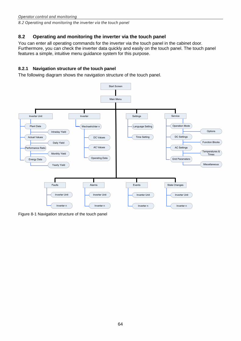
Operator control and monitoring
8.2 Operating and monitoring the inverter via the touch panel
64
8.2 Operating and monitoring the inverter via the t ouch panel You can enter all operating commands for the inverter via the touch panel in the cabinet door. Furthermore, you can check the inverter data quickly and easily on the touch panel. The touch panel features a simple, intuitive menu guidance system for this purpose.
8.2.1 Navigation structure of the touch panel The following diagram shows the navigation structure of the touch panel.
Main Menu
Start Screen
Inverter Unit
Faults Alarms
Language Setting
Time Setting
Inverter Settings Service
Events State Changes
Inverter Unit
Inverter n
Inverter Unit
Inverter n
Inverter Unit
Inverter n
Inverter Unit
Inverter n
Plant Data
Actual Values
Performance Ratio
Energy Data
Wechselrichter n
DC Values
AC Values
Operation Mode
DC Settings
AC Settings
Grid Parameters
Options
Function Blocks
Temperatures &
Times
Miscellaneous
Intraday Yield
Daily Yield
Monthly Yield
Yearly Yield
Operating Data
Figure 8-1 Navigation structure of the touch panel

Operator control and monitoring
8.2 Operating and monitoring the inverter via the touch panel
65
8.2.2 Start screen The start screen displays the current output of the solar inverter, the daily and total performance data and also includes a button which allows you to access the main menu.
Figure 8-2 Start screen of the touch panel
Legend: INVU = Inverter Unit (Master and Slaves together); INV 1 = Inverter Subunit 1, etc.

Operator control and monitoring
8.2 Operating and monitoring the inverter via the touch panel
66
8.2.3 Main menu The main menu contains buttons for calling further screens. It also contains a "Back" button which allows you to return to the start screen.
Figure 8-3 Main menu

Operator control and monitoring
8.2 Operating and monitoring the inverter via the touch panel
67
8.2.4 General operating instructions The touch panel is easy to operate by means of the buttons in the individual screens. Each touch panel screen contains a "Back" button via which you can return to the next-higher level in the menu structure. If a screen comprises more than one page, additional buttons are provided to allow you to scroll up and down between pages. The following screenshots illustrate this feature using the example of pages with fault messages. Figure 8-4 shows page 1 of the fault selection screen with faults 1 to 5. You can scroll to the next page to view faults 6 to 10 by selecting button "Faults 6-10".
Figure 8-4 Fault selection – Page 1 faults 1 to 5
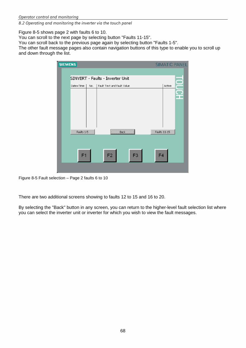
Operator control and monitoring
8.2 Operating and monitoring the inverter via the touch panel
68
Figure 8-5 shows page 2 with faults 6 to 10. You can scroll to the next page by selecting button "Faults 11-15". You can scroll back to the previous page again by selecting button "Faults 1-5". The other fault message pages also contain navigation buttons of this type to enable you to scroll up and down through the list.
Figure 8-5 Fault selection – Page 2 faults 6 to 10
There are two additional screens showing to faults 12 to 15 and 16 to 20. By selecting the "Back" button in any screen, you can return to the higher-level fault selection list where you can select the inverter unit or inverter for which you wish to view the fault messages.

Operator control and monitoring
8.2 Operating and monitoring the inverter via the touch panel
69
8.2.5 Password protected settings In addition to the screens which display current values or fault messages, for example, there are also screens in which system settings can be changed. When you call these screens, a log-on box appears which requires the input of a password, see Figure 8-6. The buttons "Settings" and "Service" in the main manu are guarded by this access protection system.
Figure 8-6 Log-on box with password input for selection of an access-protected page
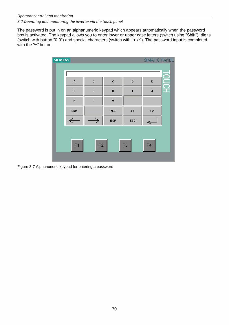
Operator control and monitoring
8.2 Operating and monitoring the inverter via the touch panel
70
The password is put in on an alphanumeric keypad which appears automatically when the password box is activated. The keypad allows you to enter lower or upper case letters (switch using "Shift"), digits (switch with button "0-9") and special characters (switch with "+-/*"). The password input is completed with the " " button.
Figure 8-7 Alphanuneric keypad for entering a password
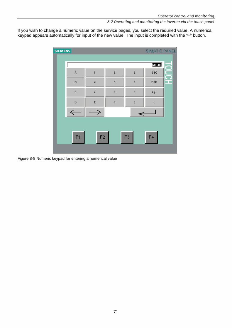
Operator control and monitoring
8.2 Operating and monitoring the inverter via the touch panel
71
If you wish to change a numeric value on the service pages, you select the required value. A numerical keypad appears automatically for input of the new value. The input is completed with the " " button.
Figure 8-8 Numeric keypad for entering a numerical value

Operator control and monitoring
8.2 Operating and monitoring the inverter via the touch panel
72
8.2.6 Inverter unit view
Figure 8-9 Inverter unit view
The pages contained in the inverter unit view provide data about the inverter unit (INVU) as well as general information and actual values. Bar charts show the intraday, daily, monthly and yearly yield. The screenshots below show the pages belonging to this view.
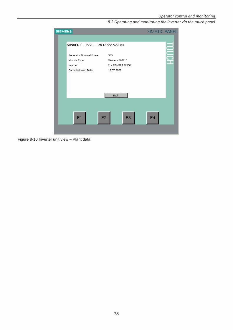
Operator control and monitoring
8.2 Operating and monitoring the inverter via the touch panel
73
Figure 8-10 Inverter unit view – Plant data

Operator control and monitoring
8.2 Operating and monitoring the inverter via the touch panel
74
Figure 8-11 Inverter unit view – Actual values
Figure 8-12 Inverter unit view – Performance ratio

Operator control and monitoring
8.2 Operating and monitoring the inverter via the touch panel
75
Figure 8-13 Inverter unit view – Energy data
Figure 8-14 Inverter unit view – Bar chart with daily yield of the current month

Operator control and monitoring
8.2 Operating and monitoring the inverter via the touch panel
76
8.2.7 Inverter view
Figure 8-15 Inverter view
The pages contained in the inverter view provide operating data about the inverter (INV) as well as DC and AC values. The screenshots below show the pages belonging to this view.

Operator control and monitoring
8.2 Operating and monitoring the inverter via the touch panel
77
Figure 8-16 Inverter view – DC values
Figure 8-17 Inverter view – AC values

Operator control and monitoring
8.2 Operating and monitoring the inverter via the touch panel
78
Figure 8-18 Inverter view – Operating data
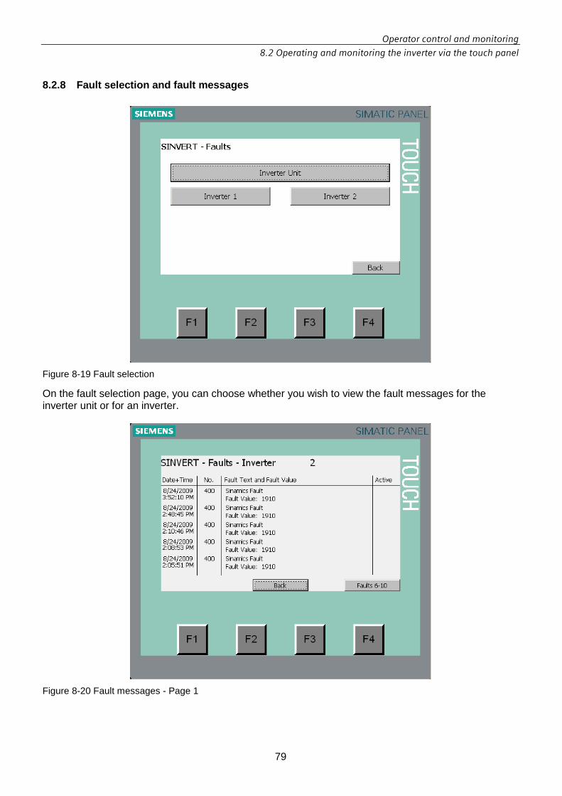
Operator control and monitoring
8.2 Operating and monitoring the inverter via the touch panel
79
8.2.8 Fault selection and fault messages
Figure 8-19 Fault selection
On the fault selection page, you can choose whether you wish to view the fault messages for the inverter unit or for an inverter.
Figure 8-20 Fault messages - Page 1

Operator control and monitoring
8.2 Operating and monitoring the inverter via the touch panel
80
8.2.9 Alarm selection and alarms
Figure 8-21 Alarm selection
On the alarm selection page, you can choose whether to view the alarms for the inverter unit or for an inverter.
Figure 8-22 Alarm selection – Alarms Page 1

Operator control and monitoring
8.2 Operating and monitoring the inverter via the touch panel
81
8.2.10 Event selection and events
Figure 8-23 Event selection
On the event selection page, you can choose whether to view the events for the inverter unit or for an inverter.
Figure 8-24 Event selection – Events Page 1

Operator control and monitoring
8.2 Operating and monitoring the inverter via the touch panel
82
8.2.11 State change selection and states
Figure 8-25 State change selection
On the state change selection page, you can choose whether to view the states for the inverter unit or for an inverter.
Figures 8-26 State change selection – States page 1

Operator control and monitoring
8.2 Operating and monitoring the inverter via the touch panel
83
8.2.12 Settings
Figure 8-27 Settings selection
Figure 8-28 Language setting

Operator control and monitoring
8.2 Operating and monitoring the inverter via the touch panel
84
Figure 8-29 Time setting

Operator control and monitoring
8.2 Operating and monitoring the inverter via the touch panel
85
8.2.13 Service
Figure 8-30 Service selection
The service pages offer numerous options for parameterizing the inverter. For example, you can • control the operating state (see Figure 8-31 Operation mode) if a service technician wishes
to switch the unit to test mode, • set the MPP window (see Figure 8-32 DC settings), • define the scope of functions by activating options or function blocks.

Operator control and monitoring
8.2 Operating and monitoring the inverter via the touch panel
86
Figure 8-31 Operation mode
Figure 8-32 DC settings

9.1 Fault messages
87
9 Fault, alarm and system messages
9.1 Fault messages Fault messages comprising the following data are displayed on the touch panel and the HTML pages:
• Time at which fault occurred • Fault text • Fault number • Fault value • Fault status
The table below shows a list of the possible fault messages.
Table 9-1 Fault messages
Fault number
Fault source Fault text Intervention required?
0-9 No Fault active No Fault active
10 GridMonitoring P2N Low Voltage PAC
11 GridMonitoring P2N High Voltage PAC
12 GridMonitoring P2P Low Voltage PAC
13 GridMonitoring P2P High Voltage PAC
14 GridMonitoring Low Frequency PAC
15 GridMonitoring High Frequency PAC
16 GridMonitoring P2P Low Voltage VSM
17 GridMonitoring P2P High Voltage VSM
18 GridMonitoring Low Frequency VSM
19 GridMonitoring High Frequency VSM
19a Grid Monitoring Single Phase Open PAC Yes
20 Rapid Stop Rapid Stop INVS 1 Yes
21 Rapid Stop Rapid Stop INVS 2 Yes
22 Rapid Stop Rapid Stop INVS 3 Yes
23 Rapid Stop Rapid Stop INVS 4 Yes

Fault, alarm and system messages
9.1 Fault messages
88
24 Rapid Stop Rapid Stop Option Slot 1 Yes
25-29 Rapid Stop Rapid Stop Option Slot 2 Yes
30 Smoke Alarm Smoke Alarm Signal 1 Yes
31 Smoke Alarm Smoke Alarm Signal 2 Yes
32 Smoke Alarm Smoke Alarm Signal 3 Yes
33 Smoke Alarm Smoke Alarm Signal 4 Yes
34 Smoke Alarm Smoke Alarm Signal 5 Yes
35 Smoke Alarm Smoke Alarm Signal 6 Yes
36 Smoke Alarm Smoke Alarm Signal 7 Yes
37 Smoke Alarm Smoke Alarm Signal 8 Yes
38 Smoke Alarm Smoke Alarm Signal 9 Yes
39 Smoke Alarm Smoke Alarm Signal 10 Yes
40-49 Optional Fault Slot 1 No Fault defined
50-59 Optional Fault Slot 2 No Fault defined
60-69 Optional Fault Slot 3 No Fault defined
70-79 Optional Fault Slot 4 No Fault defined
80-89 Optional Fault Slot 5 No Fault defined
90-99 Optional Fault Slot 6 No Fault defined
100 Peripheral Faults INVS 1 Transformer Temperature Fault
101 Peripheral Faults INVS 1 Inductor Temperature Fault
102 Peripheral Faults INVS 1 Miniature circuit breaker blown Yes
103 Peripheral Faults INVS 1 AC Resistors fault Yes
104 Peripheral Faults INVS 1 Auxiliary Switch fault Yes
105-109 Peripheral Faults INVS 1 No Fault defined
110-119 Peripheral Faults INVS 2 As for Peripheral Faults INVS 1
120-129 Peripheral Faults INVS 3 As for Peripheral Faults INVS 1
130-139 Peripheral Faults INVS 4 As for Peripheral Faults INVS 1
140-199 Optional Fault Slot 7 No Faults defined
200 Plausibility Check INVS 1 DCLinkCurrent < DCLinkCurrentMin Yes
201 Plausibility Check INVS 1 DCLinkCurrent > DCLinkCurrentMax Yes
202 Plausibility Check INVS 1 DCCurrentInput x < DCCurrentInputMin Yes
203 Plausibility Check INVS 1 DCCurrentInput x > DCCurrentInputMax Yes
204 Plausibility Check INVS 1 InsResistorValue < InsResistorValueMin Yes

Fault, alarm and system messages
9.1 Fault messages
89
205 Plausibility Check INVS 1 InsResistorValue > InsResistorValueMax Yes
206 Plausibility Check INVS 1 ACCurrentPhase x < ACCurrentPhaseMin Yes
207 Plausibility Check INVS 1 ACCurrentPhase x > ACCurrentPhaseMax Yes
208 Plausibility Check INVS 1 SupplyAirTemp < SupplyAirTempMin Yes
209 Plausibility Check INVS 1 SupplyAirTemp > SupplyAirTempMax Yes
210 Plausibility Check INVS 1 GroundingCurrent < GroundingCurrentMin Yes
211 Plausibility Check INVS 1 GroundingCurrent > GroundingCurrentMax Yes
212 Plausibility Check INVS 1 GroundingCurrentSI < GroundingCurrentSIMin
Yes
213 Plausibility Check INVS 1 GroundingCurrentSI > GroundingCurrentSIMax
Yes
214 Plausibility Check INVS 1 IrradiationModule < IrradiationModuleMin Yes
215 Plausibility Check INVS 1 IrradiationModule < IrradiationModuleMax Yes
216 Plausibility Check INVS 1 IrradiationGlobal < IrradiationGlobalMin Yes
217 Plausibility Check INVS 1 IrradiationGlobal < IrradiationGlobalMax Yes
218 Plausibility Check INVS 1 DCVoltageInput x < DCVoltageInputMin Yes
219 Plausibility Check INVS 1 DCVoltageInput x < DCVoltageInputMax Yes
220-239 Plausibility Check INVS 2 As for Plausibility Check INVS 1 Yes
240-259 Plausibility Check INVS 3 As for Plausibility Check INVS 1 Yes
260-279 Plausibility Check INVS 4 As for Plausibility Check INVS 1 Yes
280-299 Optional Fault Slot 8 No Faults defined
300 Acknowledgement INVS 1 DC Bypass Switch 1 Yes
301 Acknowledgement INVS 1 DC Bypass Switch 2 Yes
302 Acknowledgement INVS 1 DC Bypass Switch 3 Yes
303 Acknowledgement INVS 1 AC Contactor Yes
304 Acknowledgement INVS 1 AC Precharge Contactor Yes
305 Acknowledgement INVS 1 DC Precharge Resistor Switch 1 Yes
306 Acknowledgement INVS 1 DC Precharge Resistor Switch 2 Yes
307 Acknowledgement INVS 1 DC Precharge Resistor Switch 3 Yes
308 Acknowledgement INVS 1 DC Short Circuit Switch 1 Yes
309 Acknowledgement INVS 1 DC Short Circuit Switch 2 Yes
310 Acknowledgement INVS 1 DC Short Circuit Switch 3 Yes
311 Acknowledgement INVS 1 DC Grounding Power Switch Yes
312-319 Acknowledgement INVS 1 No fault defined
320-339 Acknowledgement INVS 2 As for Acknowledgement INVS 1
340-359 Acknowledgement INVS 3 As for Acknowledgement INVS 1
360-379 Acknowledgement INVS 4 As for Acknowledgement INVS 1

Fault, alarm and system messages
9.1 Fault messages
90
380-399 Optional Fault Slot 9 No Faults defined
400 Sinamics Fault Sinamics Fault

Fault, alarm and system messages
9.2 Alarm messages
91
9.2 Alarm messages Alarm messages comprising the following data are displayed on the touch panel and the HTML pages:
• Time at which alarm occurred • Alarm text • Alarm status
The table below shows a list of the possible alarms.
Table 9-2 Alarm messages of the inverter system
Alarm number
Alarm source Alarm text
1 Surge Protection Change the surge protection AC side
2 Surge Protection Change the surge protection DC side
11 Insulation Module Insulation warning
12 Insulation Module Insulation Fault
21 Transformer/Inductor Module Transformer Temperature Warning
22 Transformer/Inductor Module Inductor Temperature Warning
31 PVFieldGrounding Module PVFieldGrounding Current too high
51 Couple Switch Module Couple Switches INVS2
52 Couple Switch Module Couple Switches INVS3
53 Couple Switch Module Couple Switches INVS4
Table 9-3 Alarm messages of the inverter package
Alarm number
Alarm source Alarm text
1 Date and time Date and time are set to factory setting

Fault, alarm and system messages
9.3 Operator panel indicator signals
92
9.3 Operator panel indicator signals The indicator lights on the operator panel in the cabinet door signal the following information:
Table 9-4 Information signaled by the operator panel indicator lights
Control element State Description
Not lit • Check the line voltage.
• Please contact Technical Support.
Flashing slowly, 1s cycle
Turn the "On / Off" keyswitch to the "On" position.
Flashing fast, 250ms cycle
No action necessary.
Note: If no fault signal is active and the solar inverter does not switch to the "Run" state despite adequate insolation, then please check the following:
• The DC-side fuses.
• The polarity of the PV field connection is correct.
Green indicator light
"Run"
Illuminated steadily
No action necessary.
Not lit No action necessary.
Flashing slowly, 1s cycle
An alarm is active. The inverter remains in operation, but maintenance is required.
Flashing fast, 250ms cycle
No action necessary because the solar inverter will automatically acknowledge the fault after a specific period.
Yellow indicator light
"Fault"
Illuminated steadily
A fault which requires manual acknowledgement is active.

Service and maintenance
10.1 Service
93
10 Service and maintenance
10.1 Service The term "servicing" refers to any measure which restores the cabinet to a fully functional operating state.
10.1.1 Replaceable components You are allowed to replace the following components.
• Fuses • Surge arresters • Transformer and inductor fans • Inverter fan

Service and maintenance
10.2 Maintenance
94
10.2 Maintenance The term "maintenance" refers to any measure which maintains the cabinet in a fully functional operating state.
10.2.1 Maintenance intervals You must carry out the following maintenance work at the indicated intervals to ensure the long-term operability of the inverter cabinet.
Table 10-1 Maintenance concept
Maintenance Interval Clean the inside of the cabinet. At least 1 x per year Tighten conducting screw connections. At least 1 x per year Replace the surge arresters. Every 10 years. Replace the cabinet fans. Every 15 years. Replace the Active Line Module fan. (service life: 50000 hours)
Every 13 years.
IMPORTANTIMPORTANTIMPORTANTIMPORTANT Maintenance intervalsMaintenance intervalsMaintenance intervalsMaintenance intervals The actual maintenance intervals depend on the cabinet's environment and operating conditions.

Service and maintenance
10.3 Cleaning the inside of the cabinet
95
10.3 Cleaning the inside of the cabinet
10.3.1 Requirements • Cleaning brush and vacuum cleaner are available. • A supply of oil-free compressed air up to maximum 1 bar is available. • You have read and adhered to the instruction below: Decommissioning the inverter
(Chapter 7). • The feeders at the DC and AC inputs are de-energized. • A voltage tester is available. • A cabinet key is available.
10.3.2 Procedure 1. Open the cabinet door. 2. Use the voltage tester to make sure that the cabinet is de-energized. 3. Use the brush and vacuum cleaner to remove dust deposits on easily accessible
components. 4. Use dry compressed air at a pressure of maximum 1 bar to clean dust deposits off less
easily accessible components. 5. Close the cabinet door. 6. Energize the feeders at the DC and AC inputs again. 7. Commission the control cabinet on again. (Chapter 7)

Service and maintenance
10.4 Tightening conducting screw connections.
96
10.4 Tightening conducting screw connections.
10.4.1 Torques for conducting screw connections The following torques must be applied to check the tightness of all conducting screw connections:
Table 10-2 Torques for conducting screw connections
10.4.2 Requirements • You have read and adhered to the instruction below: Decommissioning the inverter
(Chapter 7). • The feeders at the DC and AC inputs are de-energized. • A voltage tester is available. • A cabinet key is available.
10.4.3 Procedure 1. Open the cabinet doors. 2. Use the voltage tester to make sure that the cabinet is de-energized. 3. Use the torque wrench to tighten the DC and AC screw connections. Refer to Table 10-2. 5. Close the cabinet doors. 6. Energize the feeders at the DC and AC inputs again. 7. Commission the control cabinet on again. (Chapter 7)
Screw Torque AC outputs 60 Nm / 442.53 Lb-in DC inputs 60 Nm / 442.53 Lb-in Grounding 60 Nm / 442.53 Lb-in

Service and maintenance
10.5 Replacing the inductor and transformer fans
97
10.5 Replacing the inductor and transformer fans
10.5.1 Requirements • You have read and adhered to the instruction below: Decommissioning the inverter
(Chapter 7). • The feeders at the DC and AC inputs are de-energized. • A voltage tester is available. • A cabinet key is available.
10.5.2 Procedure 1. Open the cabinet doors. 2. Use the voltage tester to make sure that the cabinet is de-energized. 3. Disassemble the fan trays and remove the plug-in connection of the fans Take out the fans and replace them with new ones. 4. Install the fan trays with the new fans. 5. Close the cabinet doors. 6. Energize the feeders at the DC and AC inputs again. 7. Commission the control cabinet on again. (Chapter 7)

Service and maintenance
10.6 Replacing the inverter fan
98
10.6 Replacing the inverter fan
10.6.1 Torques for screw connections on the inverte r
Table 10-3 Torques for screw connections on the inverter
10.6.2 Requirements • You have read and adhered to the instruction below: Decommissioning the inverter
(Chapter 7). • The feeders at the DC and AC inputs are de-energized. • A voltage tester is available. • A cabinet key is available.
10.6.3 Procedure 1. Open the cabinet doors. 2. Use the voltage tester to make sure that the cabinet is de-energized. 3. Take the protective covers off the inverter. 4. Undo the screws in the order indicated in the picture and replace the inverter fan. 5. Then follow the sequence in reverse to install the new fan. Attach the protective covers
again. Please adhere to the torques specified in Table 10-3.
6. Close the cabinet doors. 7. Energize the feeders at the DC and AC inputs again. 8. Commission the control cabinet on again. (Chapter 7)
Screw Torque M6 6 Nm / 53.104 Lb-in M8 13 Nm / 115.059 Lb-in M10 25 Nm / 221.268 Lb-in M12 50 Nm /442.537 Lb-in

Service and maintenance
10.7 Separating the Inverter from DC input
99
10.7 Separating the Inverter from DC input
10.7.1 Requirements
• You have read and adhered to the instruction below: Decommissioning the inverter (Chapter 7).
• A cabinet key is available
10.7.2 Procedure To separate one inverter from the DC input perform the following steps:
1. Shut down all inverters are connected by the DC bus. 2. Disconnect all inverters are connected by the DC bus using the external disconnector. 3. Wait 5 minutes for DC-link capacitors discharging and then safely measure the
voltage between each fuse terminal and ground to ensure no hazardous potential exists at either end of fuse.
4. Open the left side DC cabinet door by key 5. Remove the 3 x 400A fuses (and the removable 3 copper bars in the grounding) of the
inverter to be isolated. On this way you can ensure the physical and visible isolation of the inverter from the local PV arrays.
6. Remove the associated DC bus fuses (2x600 A) or/and the removable copper bars (at the same place). The inverter is now completely isolated from all the PV arrays in the system.
7. Close the cabinet doors. 8. To restart the remaining systems, close the external disconnector for other units and start up
those inverters.
WARNINGWARNINGWARNINGWARNING DC side disconnect is not part of the system. To disconnect the inverter from the DC input for service proposes use an external disconnect.

Service and maintenance
10.8 Fuse Sizing for the DC Bus
100
10.8 Fuse Sizing for the DC Bus The DC Bus connections are protected by fuses. The fuses are not requested in the grounded pole. In case of negative grounding (default) install the fuses on the positive pole. In case of positive grounding install the fuses on the negative pole. In dependency of the number of slaves the following calculation shold be used:

Service and maintenance
10.9 Separating the Inverter from AC Output
101
10.9 Separating the Inverter from AC Output
10.9.1 Requirements
• You have read and adhered to the instruction below: Decommissioning the inverter (Chapter 7).
• A cabinet key is available
10.9.2 Procedure To separate the inverter from the AC output perform the following steps:
1. Open the AC output contactor by software through stopping the system. 2. Disconnect all inverters are connected by the DC bus using the external DC disconnector. 3. Disconnect the inverters from the AC output using the external AC disconnector. 4. Wait 5 minutes for DC-link capacitors discharging and then safely measure the
voltage between each fuse terminal and ground to ensure no hazardous potential exists at either end of fuse.
5. Open the right side AC cabinet door by key 6. Turn off the internal AC disconnector (to OFF position).
WARNINGWARNINGWARNINGWARNING To disconnect the inverter from the AC Output an external disconnect is to be provided during installation.
CAUTIONCAUTIONCAUTIONCAUTION
Disconnect also the Auxiliary Power Supply before open the cabinet. To disconnect the Auxiliary Power Supply an external disconnect is to be provided during installation.

Technical data
11.1 Environmental conditions
102
11 Technical data
11.1 Environmental conditions
Storage
Conditions for long-term storage Classification
Climatic environmental conditions 1K2
Biological environmental conditions 1B1
Chemically active substances 1C1
Mechanically active substances The devices must be stored such that they are protected against the ingress of sand or dust.
With respect to the climatic environmental conditions, the following supplementary condition is defined in a departure from class 1K2:
Conditions for long-term storage Value
Ambient temperature -25 °C to +70 °C
Air humidity (relative) 5 % to 95 %
Shipping (values apply to packaged goods)
Conditions during shipment Classification
Climatic environmental conditions 2K2
Biological environmental conditions 2B1
Chemically active substances 2C1
Mechanically active substances 2S2
With respect to the climatic environmental conditions, the following supplementary condition is defined in a departure from class 2K2:
Conditions during shipment Value
Ambient temperature -25 °C to +70 °C
Air humidity (relative) 5% to 95 %

Technical data
11.1 Environmental conditions
103
Operation
Conditions during operation Classification
Climatic environmental conditions 3K3
Biological environmental conditions 3B1
Chemically active substances 3C1
Mechanically active substances To ensure long-term reliable operation of the equipment, suitable measures must be taken to prevent the ingress of dirt and dust.
With respect to the climatic environmental conditions, the following supplementary condition is defined in a departure from class 3K3:
Conditions during operation Value
Ambient temperature (with derating) 0 °C to 50 °C
Ambient temperature (without derating) 0 °C to 40 ° C
Air humidity (relative) 0 % to 95 %
Installation altitude (without derating) <=2000m
Installation altitude (with derating) >2000m
Cooling
Cooling method: Forced cooling by means of fans Air inlet Front of cabinet Air discharge Top of cabinet

Technical data
11.2 Mechanical data
104
11.2 Mechanical data
Characteristic Specification Value
Dimensions – without pallet (W x H x D)
Per control cabinet (*) 1402 x 2200 x 745 mm
Ground DC cabinet incl. pallet Approx. 1100 kg
AC cabinet incl. pallet Approx. 1900 kg
Total system incl. pallet Approx. 3000 kg
Color RAL 7035
Surface of cabinet Powder-coated
Degree of protection according to EN 60529-1 IP21
Conductor cross-section PV field 300mm²
Power grid L1, L2, L3 2x240mm²
Power grid PE 240mm²
Ring terminal lug Power grid L1, L2, L3 M12
Noise level < 75 db (A)
Remark (*): The roof of the cabinet can be easialy removed for transport. In this case the height of the cabinet is 2100 mm.

Technical data
11.3 Electrical data
105
11.3 Electrical data
Output data (AC)
Maximum output voltage VL-L acmax V 528 (480+10%)
Minimum output voltage VL-L acmin V 422 (480-12%)
Rated grid voltage VL-Lac,r V 480
Rated frequency fr Hz 60
Maximum grid frequency fmax Hz 60.5
Minimum grid frequency fmin Hz 59.3
Rated power Pac,r kW 350
Maximum power kW 385
De-rated power (at ambient 50°C) kW 305
Maximum output current Iacmax A 424
Maximum output over current protection A 500
Maximum output fault current and duration A 2400 (instantaneous)
AC short circuit current A 2400
cos phi Pac,r > 0.99
Input data (DC)
MPP voltage range Vmppmin - Vmppmax V 330 to 480
Start input voltage range Vdcstart V 430
Maximum system voltage V 600
Maximum operating input voltage Vdcmax V 600
Minimum operating input voltage Vdcmin V 330
Nominal input power kW 364
Maximum input current Idcmax A 1103
Number of DC inputs 3
Maximum current per input A 368
Maximum continuous utility back feed current A 0
Maximum fault back feed current per input (**) A 400
Over current protection (per input) A 400
Master Slave interconnection bus (DC)
Maximum system voltage V 600
Maximum current (2 x 600A fuses) A 1200
Maximum continuous utility back feed current A 0
Maximum fault back feed current (**) A 1200 Remark (**): in case of IGBT short circuit failure.

Technical data
11.3 Electrical data
106
Efficiency 330 V 480 V
CEC (***) at 100 % nominal power % 95,9 95,6
CEC at 75 % nominal power % 97,2 96,4
CEC at 50 % nominal power % 97,1 96,4
CEC at 30 % nominal power % 97,1 96,1
CEC at 20 % nominal power % 96,7 95,2
CEC at 10 % nominal power % 94,8 91,9
CEC weighted efficiency % 97,1 96,3
Maximum efficiency % 97,2
Power loss in night-time operation Master / Slave W 205 / 50
Maximum current external infeed / optional (AC) A 15
Galvanic isolation by LV transformer
Option interconnection
Analog & Digital I/O ports Ethernet connection / Optional inputs
Analog & Digital I/O Maximum ratings Standard Ethernet / Optional input signals < 10 V
Auxiliary Power supply, Nominal Voltage 480 VAC 3 phase
Auxiliary Power supply, maximum Current (****) A 15
Auxiliary Power supply, min. power need (*****) W 2600
Output for first external load 480 VAC 3 phase / 15A
Output for second external load 230 VAC / 10A
Remarks (***): CEC = California Energy Commission (****) in combination with option external load (*****) without option external load
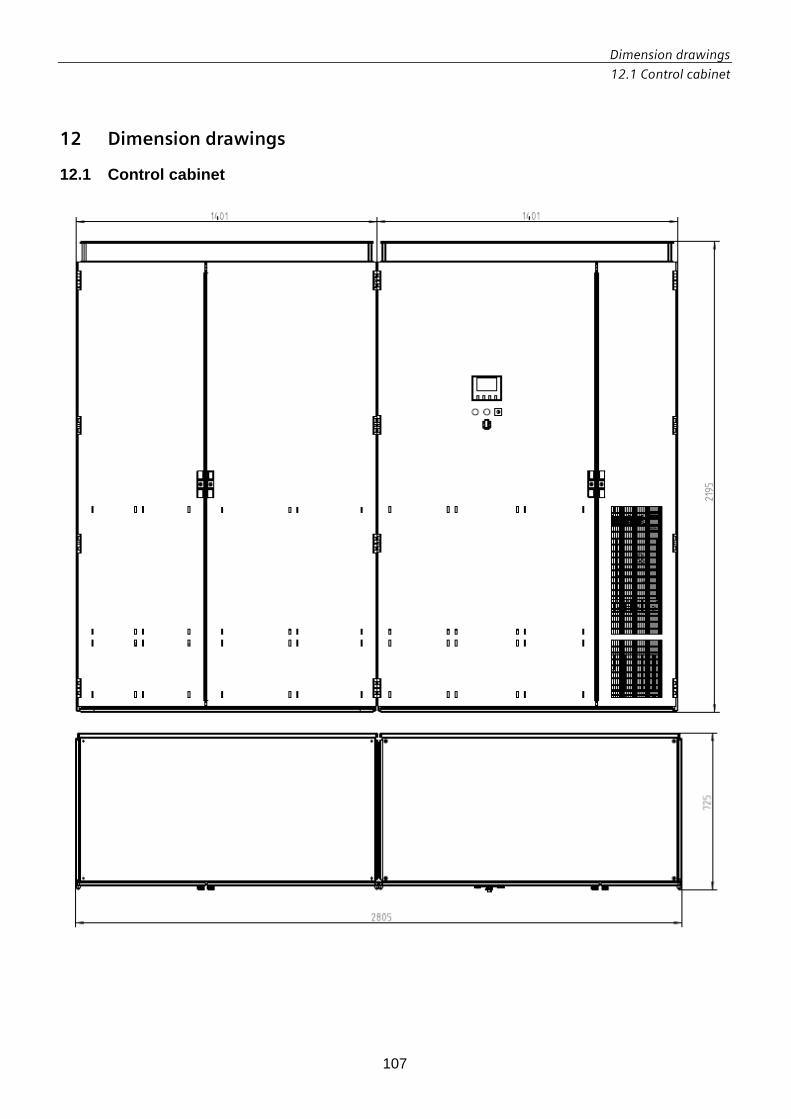
Dimension drawings
12.1 Control cabinet
107
12 Dimension drawings
12.1 Control cabinet

Dimension drawings
12.2 Base plate and drilling pattern
108
12.2 Base plate and drilling pattern The base plate must be prepared as shown in the drawing for mounting of the cabinet. Dimensions are in mm.

Technical support
13.1 Sales
109
13 Technical support
13.1 Sales E-mail: [email protected] Internet: www.siemens.de/sinvert www.siemens.com/sinvert
13.2 Service Do you need service support for your SINVERT inverters? Online support: http://www.siemens.com/automation/support-request The support hotline for SINVERT can be reached on the following numbers from Monday to Friday between 8 am and 5 pm (ET): Phone: +1 800 333 7421

Further information www.siemens.com/sinvert
Siemens AG Industry Sector, IA CE S PV P.O. Box 2355 90766 Fuerth GERMANY
Subject to change
© Siemens AG 2011
www.siemens.com