001 Technical Investigation
8
TECHNICAL INVESTIGATION University of Pretoria etd, Lotz W. (2006)
Transcript of 001 Technical Investigation

89
TECHNICAL INVESTIGATION
UUnniivveerrssiittyy ooff PPrreettoorriiaa eettdd,, LLoottzz WW.. ((22000066))

90 91
Extension in Marseille, Marseilles, France, 2001. Architect: Remy Mar-ciano
The project provides an open-air patio for an existing building. It consists of one element, perforated sheet metal cladding which serves as an all-enveloping facing that provides an intimate setting for the existing enclosure within.
The project is set adjacent to a park and attempts to find a syn-thesis between the building and its natural surroundings, becom-ing the point where building and nature meets. The perforations are a repeated pattern that resembles something between the abstract and naturalistic. (Aymonino 2006: 308)
FIG. 6.4
DESIGN INFLUENCES
Green Green Screen, Tokyo, Japan, 2003. Archi-tect: Klein Dytham Architecture.
This is a temporary work of architecture, which consists of a facade - a wall of plants. This temporary enclosure is a hybrid that integrates vegetation and printed graphics of abstract floral motifs. As result, a rich texture filled facade that communicates with pedestrians, which is somewhere between the naturalistic and the artificial. (Aymonino 2006: 308)
FIG. 6.2
FIG. 6.3
UUnniivveerrssiittyy ooff PPrreettoorriiaa eettdd,, LLoottzz WW.. ((22000066))

92 93
BRICKPretoria does have a brick aesthetic and many build-ings in the CBD are char-acteristically concrete frame structures with brick infill, as is the case of the proposed development.
Brick has low embodied energy and is produced locally. The erection of brick structures in South Africa relies on cheap and intensive labour carried out by local brick-layers, empowering the local labour force. Brick has good thermal mass and load-bearing/structural proper-ties. Furthermore, brick is recycla-ble and easily reused.
The proposed project requires two different types of bricks: stock brick that will be hidden by cladding and purely serve the function of add-ing thermal mass, and acoustic bricks to be used as face brick in the interior of the building. The aes-thetic appeal of the acoustic bricks is illustrated by the interior of the Cambridge Crystallographic Data Cen-tre in Cambridge, England (FIG. 6.6, above), designed by Eric Sorensen (1992). It serves the additional function of reducing traffic noise (Campbell & Pryce 2003: 285).
MATERIAL SELECTION
CONCRETEThe superstructure of the proposed development is a reinforced column and slab structure, including rein-forced concrete shear walls, concrete roof and some exterior / interior walls.
The advantages of concrete construc-tion is numerous and include:Good thermal mass due to high densityIt can achieve large spans.Concrete is easily moulded and cast in-situ on site.Concrete can have various finishes and textures, depending on the form-work and through adding iron oxide pigments.New advances in technology allows for the production of translucent con-crete, by adding crushed fibre op-tics, illustrated below (FIG. 6.6).
The proposed project requires the reinforced concrete walls to be cast with rough-sawn timber formwork shut-tering on the exterior and plywood formwork shuttering on the interior. Furthermore, the project requires that dark blue-grey, iron oxide pigment be added to the concrete mix. Steven Holl beautifully illustrates the desired effect in the concrete finishes in the lobby of Simmons Hall (2002), MIT, above (FIG.6.5). The cost of pig-mented concrete can be justified through robustness of the finish compared to plaster and paint.
UUnniivveerrssiittyy ooff PPrreettoorriiaa eettdd,, LLoottzz WW.. ((22000066))
94 95
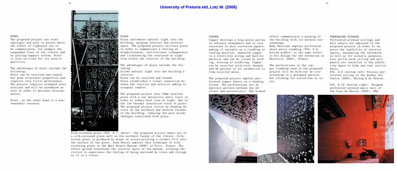
COPPERCopper develops a blue-green patina in ordinary atmosphere and is very resistant to most corrosion agents, making it suitable as a cladding or roofing material. Annealed copper is a relatively strong and ductile material and can be joined by weld-ing, brazing or soldering. Copper can be recycled relatively cheaply and 40 percent of all production is from recycled metal.
The proposed project employs per-forated copper sheets as a shading screen. The perforations are an abstract pattern between the ab-stract and naturalistic. The wished
effect communicates a merging of the building with its natural sur-roundings.Remy Marciano employs perforated sheet metal cladding (FIG. 6.9, bottom middle) to the same effect in his design for the extension in Marseille (2001), France.
The perforations in the cop-per cladding used in the proposed project will be weld-cut on site according to a designed pattern, but allowing for variations to oc-cur.
PERFORATED PLYWOOD Perforated plywood ceilings and wall panels are employed in the proposed project in order to im-prove the legibility of interior spaces, announcing the threshold, as well as for acoustic purposes. Lacy grille-work ceiling and wall panels are installed in the exhibi-tion space to hide and vent service ducts. FIG. 6.8 (bottom left) Paisley per-forated ceiling of the Walker Art Centre (2005), Herzog & de Meuron.
FIG. 6.10 (bottom right). Wrapped perforated plywood music hall of the Casa da Musica (2005), OMA.
STEELThe proposed project use steel sparingly and only in places where the effect of lightness are to be communicated, for example the suspended floor of the library and as glazing support system. Steel is also utilised for its tensile qualities.
The advantages of steel include the following:Steel can be recycled and reused, has good structural properties and;requires very little maintenance.The project requires standard steel sections and will be assembled on site in order to decrease discrep-ancies.
Steel, on the other hand is a non-renewable resource.
GLASSGlass introduces natural light into the building, merging interior and exterior space. The proposed project utilizes glass in order to communicate a feeling of weightlessness, institutional transparency and illuminating the courtyard at night from within the interior of the building.
The advantages of glass include the fol-lowing:Allows natural light into the building’s interior.Glass can be recycled and reused.Glass establishes a visual connection be-tween the interior and exterior adding to occupant comfort.
The proposed project uses 19mm insulvue glass with a low emissivity outer layer in order to reduce heat loss at night, due to the low thermal insulation value of glass.The proposed project relies on shading de-vices on the northern and western facades of the building, reducing the most disad-vantages associated with glass.
Silk-screened glass (FIG. 6.7, above): the proposed project makes use of a silk-screened glass wall on the northern facade of the library. Silk-screen glass is produced by means of screen-printing a ceramic frit onto the surface of the glass. Jean Nouvel employs this technique of silk screening glass in the Quai Branly Museum (2006) in Paris, France. The effect gained transforms the interior space of the museum, allowing the visitor to experience the feeling of being enclosed by trees and foliage as if in a forest.
UUnniivveerrssiittyy ooff PPrreettoorriiaa eettdd,, LLoottzz WW.. ((22000066))

96 97
ROOF CONSTRUCTION
ROOF CONSTRUCTIONThe roof construction of the pro-posed project consists of a re-inforced concrete roof, either a simple concrete construction or a planted concrete roof (FIG. 6.13).
The concrete roof construction re-quires a minimum screed thickness of 40mm along with a minimum gradi-ent of 1:50 according to the NBR L5.3. The reinforced concrete roof slabs are 255mm / 340mm thick, with 255mm to 510mm high parapet walls.
Waterproofing of the concrete roof consist of a cement screed with a minimum thickness of 40mm with a 1:50 gradient; a double layer 4mm modified bitumen membrane with 100mm side laps and 150mm end laps, sealed by means of torch-on fusion;The waterproofing membrane is then covered with dry stacked 500 x 500 x 80mm precast concrete cover tile.The waterproofing membrane are tak-en up 200mm against parapet walls and protected with galvanised steel flashing.
100mm diameter PVC down pipes is cast into the reinforced concrete end columns at 5.3m & 5m intervals.
The planted reinforced concrete
roof construction consist of a ce-ment screed with a minimum thick-ness of 25mm and a maximum of 250mm and a double layer modified bitu-men waterproofing membrane on top of the screed. The waterproofing is covered with a 50mm, galva-nised steel mesh reinforced, cement screed; a 50mm layer of (19mm di-ameter) stone wrapped in a geotex-tile; and 250mm topsoil.
STRUCTURE
Concrete column and slab
Movement joints
Reinforced concrete walls
The off-shutter reinforced concrete columns are 260 x 300mm and 260 x 400mm (bigger column dimensions to support the auditorium, between the Gallery and the vehicular ramp leading down to the basement level. All columns to have 20mm chamfered edges and cast in storey heights. Concrete to be cast with vertical move-ment joints at 10,6 m intervals and must be a clean break through the entire structure. Vertical movement joints in the reinforced concrete walls of 10mm bitumen-impregnated soft board. The rein-forced concrete slabs are 340mm thick with a maximum span of 8,6 meters. All reinforced concrete shear walls are 200mm thick.
Sculptural columns slanted at 14 degrees with the vertical
FIG. 6.11 (bottom) Structural layout and materialsFIG. 6.12 (top) First floor plan.
UUnniivveerrssiittyy ooff PPrreettoorriiaa eettdd,, LLoottzz WW.. ((22000066))
98 99
OFFICEOFFICE
OFFICE
LIBRARY
BASEMENT
AUDITORIUM
EXHIBITION SPACE PLANT ROOM
VEHICULAR RAMP
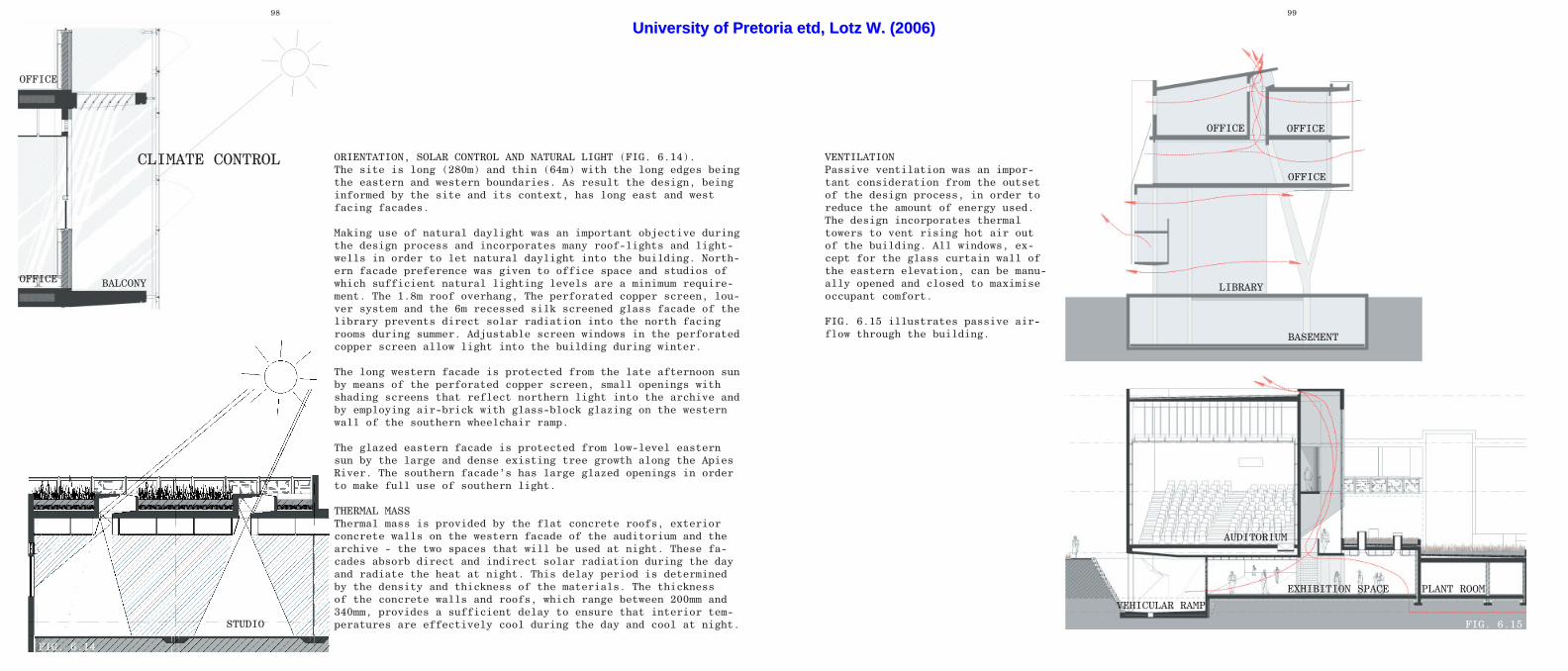
VENTILATIONPassive ventilation was an impor-tant consideration from the outset of the design process, in order to reduce the amount of energy used. The design incorporates thermal towers to vent rising hot air out of the building. All windows, ex-cept for the glass curtain wall of the eastern elevation, can be manu-ally opened and closed to maximise occupant comfort.
FIG. 6.15 illustrates passive air-flow through the building.
FIG. 6.15
ORIENTATION, SOLAR CONTROL AND NATURAL LIGHT (FIG. 6.14).The site is long (280m) and thin (64m) with the long edges being the eastern and western boundaries. As result the design, being informed by the site and its context, has long east and west facing facades.
Making use of natural daylight was an important objective during the design process and incorporates many roof-lights and light-wells in order to let natural daylight into the building. North-ern facade preference was given to office space and studios of which sufficient natural lighting levels are a minimum require-ment. The 1.8m roof overhang, The perforated copper screen, lou-ver system and the 6m recessed silk screened glass facade of the library prevents direct solar radiation into the north facing rooms during summer. Adjustable screen windows in the perforated copper screen allow light into the building during winter.
The long western facade is protected from the late afternoon sun by means of the perforated copper screen, small openings with shading screens that reflect northern light into the archive and by employing air-brick with glass-block glazing on the western wall of the southern wheelchair ramp.
The glazed eastern facade is protected from low-level eastern sun by the large and dense existing tree growth along the Apies River. The southern facade’s has large glazed openings in order to make full use of southern light.
THERMAL MASSThermal mass is provided by the flat concrete roofs, exterior concrete walls on the western facade of the auditorium and the archive - the two spaces that will be used at night. These fa-cades absorb direct and indirect solar radiation during the day and radiate the heat at night. This delay period is determined by the density and thickness of the materials. The thickness of the concrete walls and roofs, which range between 200mm and 340mm, provides a sufficient delay to ensure that interior tem-peratures are effectively cool during the day and cool at night.
CLIMATE CONTROL
STUDIO
BALCONYOFFICE
OFFICE
FIG. 6.14
UUnniivveerrssiittyy ooff PPrreettoorriiaa eettdd,, LLoottzz WW.. ((22000066))

100 101
The success of a recording stu-dio depends solely on its acoustic efficiency. The recording studio consists of three important spaces: The live room, the control booth and the piano room. The record-ing studio is situated right next (north) to the auditorium.
None of the live room’s walls are parallel to one another as is the case with the floor and ceiling to prevent the occurrence of standing waves. The construction consists of 510mm thick cavity walls with a 50mm cavity. The floating timber floor’s construction consist of 32mm thick tongue and groove timber floor planks nailed to 94 x 44mm timber battens, which is isolated from the concrete floor with 10mm neoprene seals (alternating be-tween RC floor - timber batten and Timber floor plank – timber bat-ten) in order to prevent structural
Control room
Live room
Piano room
Equiptment storage
noise. The live room has a 12mm plywood veneer hanging ceiling hiding HVAC ducts (with incorporated acoustic absorbers).
The access doors to the live room from the control room and to the equipment storage are double timber doors with a cavity between them, sealed with 25mm Sondor neo-prene seals all along the door-jambs. All glazed openings (view panel between the live- and control room) are double-glazed and not parallel to one another. The bigger the cavity between the two lami-nate glass panels, the better the acoustic isolation. Copper sulphate should be inserted into the cavity to absorb any moisture.
The glass sliding door of the piano room is a 45dB sound proof door and consist of two sliding doors.
The piano room wall construction consist of 510mm cavity walls with a 50mm cavity; 32 x 69mm timber battens fixed to brick wall with 50mm mineral wool blanket with fabric covering in the cavity and fixed to the wall, perforated ply-wood veneer panels screwed to the timber battens. A similar wall con-struction will be employed for the control room.
ACOUSTICS
The auditorium (FIG. 6.16) is a concrete box overhanging the ve-hicular ramp leading down into the basement. The shape of the audi-torium was designed to prevent the occurrence of standing waves (standing waves occur when sound waves are trapped between two par-allel walls). No walls are paral-lel to one another and the floor and ceiling differ in gradient. The walls are 200mm thick reinforced concrete.
Both access points to the audi-torium have double wooden doors with a cavity between them and the doorjamb sealed with a 25mm neo-prene seal. All glazed openings to
be double-glazed and not parallel to one another. The cavity is supplied with copper sulphite in order to absorb moisture be-tween the two laminat-ed glass panes.
The wall construction consists of a 200mm reinforced concrete wall; 50mm mineral wool blanket with a black fabric covering fixed to the wall; a
76 x 38 x 2.0 mild steel RHS frame fixed to the concrete columns (with 5000mm centres) but isolated from the concrete structure with 10mm neoprene seals in order to prevent structural noise; 8mm x 1750 x 1080 red stained perforated plywood pan-els fixed to steel structure. The cavity between the concrete wall and the plywood panels is 130mm.
The front third of the side walls and ceiling are covered by red stained plywood with ø3 holes at a 13.5mm pitch which allows for a 21.1% open area and functions as a sound reflector (Fig.) The remain-ing two thirds of the side walls, ceiling and rear wall are covered by perforated plywood with ø7 hole @13.5mm pitch which allows for a 11% open area and functions as ab-sorber of low frequencies and pre-vent echoes (Fig.). The front wall serves as a acoustic reflector and has a fairfaced concrete finish.
FIG. 6.16 Auditorium
UUnniivveerrssiittyy ooff PPrreettoorriiaa eettdd,, LLoottzz WW.. ((22000066))

102 103
FIG. 6.17 Second floor plan. NTS
5.1m20.8m
12.3m
13.1m
24.7m
16.0m
12.6m
23.8m
5.3m
34.0m
5.7m
16.3m
36
35
34
33
32
31
30
29
28
27
23
24
2537
26
5352
5150
49
5455
5657
5859
6061
626364
40
41
42
43
44
45
46
47
48
49
50
51
52
53
27282930313233343536373839
41
42
43
44
45
46
47
48
49
50
51
52
53
40
01
02
03
04
05
06
07
08
09
10
11
12
13
14
15
16
17
18
19
20
21
25
24
23
22
21
20
19
18
17
16
1 5
14
13
12
1 1
10
09
08
07
06
05
04
03
0102
22
26
54
55
56
57
58
59
60
61
62
63 64
65
66
67
68
4.600
4.600
4.430
Double volumeService
duct
Kitchen
Skylight
downStairs
1: 12 Ramp down
2.550
3.400
Planted terrace
Amphitheatre
Step
sup
Terrace steps up
4.600
Studio 5
Kitchen
male
Female
Archive
entranceComputer lab
1: 12 Ramp up
5.450
1: 12 Ramp up
Piano room
Live room
Double volume
Control
room
Rear projection
room
Sampling
studio
Equiptment
storage
5.450
6.400
Auditorium
0.630
4.515
Covered patio
4.515
Covered patio
4.600
Service duct
Restroom
Corporate lounge
Conference
room
Conference
roomSafe
reception
Director's
office
library
libraryassistance
3.185
1:12
Rampdown
library
Double volume
Double volume
Double volume Walkway 1500mm wide
Double volume
Fireescape
up
4.515
Coveredpatio
4.515
Coveredpatio
Walkway 1600mm wide
Service duct
2.300
Studio 4
Participant lounge
AA
AA
BB BB
CC
CC
DD
DD
EE
EE
BABB
BC BD
A B C D E F G H J K L M N P Q
T U V W
R S T U V W X Y Z AA AB AC AD AE AF AG AH
X Y Z AA AB AC AD AE AF AG AH
54
32
1
67
89
10
BABB
BC BD
12
13
14
R
11
INCLUSIVITY
The Communication Research Centre as well as the public amenities provide for the old and infirm. Wheelchair ramps, to provide disa-bled access to the fist floor from ground floor level, are provided in the library, exhibition space and the southern wing of the de-sign school that links the school administration with the studios on ground and first floor levels. The entrance to the archive, which is two levels high, is on the first floor level with a wheelchair ramp giving access to the upper level. The auditorium has wheelchair ac-cess on ground level as well as on the first floor level.The courtyard can be accessed by ramps leading up from the Apies River level, down from the library and the entrance foyer respective-ly.
All ramps have a maximum gradi-ent of 1:12 with resting platforms every two meters of vertical rise.
The ground floor level as well as the first floor level has toilets for use by disabled persons that comply with the requirements set by section S of the National building regulations.
FIRE STRATEGY
The National building regulations stipulates in section TT 16.2 that a building with three or less sto-reys in height is not required to include and emergency escape route.
The NBR further specifies that the travel distance, measured to the nearest escape door, must not ex-ceed 45m. The corporate wing of the proposed project is four storeys high and requires two emergency escape routes (FIG. 6.17).
The NBR further requires, section TT 7, that structural elements are to have a fire resistance as fol-lows:The restaurant, recording studio, auditorium and workshop – 60 min-utesThe exhibition space – 90 minutesOffices and art studios – 60 min-utesThe concrete structure will provide sufficient fire resistance. The structural steel members of glass curtain wall on the eastern façade requires an in tumescent mas-tic fire resistant coating thinly painted on the members after a coat of steel primer has been applied.
UUnniivveerrssiittyy ooff PPrreettoorriiaa eettdd,, LLoottzz WW.. ((22000066))