
00000001 - NASA · AC_O_EDG_ENT The authorwishes to acknowledBethe contributionsto the p_eparation...
114
MS_Co 1_(em3190 (Rev ]tme 1971) i L" • :. __+4 .............. +- https://ntrs.nasa.gov/search.jsp?R=19740022193 2019-02-03T21:53:58+00:00Z
-
Upload
truongthien -
Category
Documents
-
view
213 -
download
0
Transcript of 00000001 - NASA · AC_O_EDG_ENT The authorwishes to acknowledBethe contributionsto the p_eparation...

MS_C o 1_(em3190 (Rev ]tme 1971)i
L" • :. __+4 .............. +-
00000001
https://ntrs.nasa.gov/search.jsp?R=19740022193 2019-02-03T21:53:58+00:00Z

..... TI_CHNICA . REPORT STAHPARI_ TITLE PA61_
-F-h-_po,T .0, ...... _, _O_dN_J.T AccP.'_eIOH.0, s, R_.i:-Ipt_HT,eCATA-t.bGNO;NASA TM X,-.,fi4852
i4 TITLI_ ANO BUItTITLB IL REPORT DATF. !
Jub' t 74. 1SKYI,AB TIIRUSTER ATTITUDE CONTROL SYSTEM _. P_RVORMINO0RGAklZATmNC00_":
7, G,AUT"0RIS)E,Wilmer, Jr, 8,.P_Eae.oa_mabRakmza_riON_Er'OR(" 1]I I' i I' ii II , ii Iiii i' I [ I IIIII I ,
B, PERFORMING ORGANIZATION NAME AND ADDRE_ 10, WORK UNIT, NO, 1
ii i l !George C. Marshall Space Flight Centor_ I t, CONTRACTO"_RA_' .0, ,Marshall Space Flight C_nter, Alabama 35812 tf ,"
_3. rOPEo_'REPOt',• PERiO0COVEREO tJ r I . , ,-
112 'SPONSORING AGgI_OY NAME ANO AOORESSTechnical Me.morandum {
NationalAeronauticsand Space Administration
Washington, D.C. 20546 14, $PONI_ORtN6 AGEN'OYCODE
_1 a i BII ii IB i J ii
su,, EM NTARY"NOTES
16, ABSTRACT
This report doctwnents the preflightactivitiesand the Skylab mission sctppo=teffortfor the Thruster Attitude Control System (TACS). The preflightaCtLvtties
include a description of problems and their solutions encountered in the developmenh
qualification,and flightcheckout testprograms. The mission support effort ispresented as it relates to system performance assessment, real-time problemsolving, flightanomalieS, and the daily system evah_.tion. Finally, the detailed "
: flightevaluation is presented for each phase of the mission using system telemetrydata.
The report asserts that the TACS met or exceeded design requirements a_d
fulfilled i_s assigned mission objectiveS.
'I"L"KE'_V_(_ROS ' ' i8. DISTRII3UTIONSTATE_Et/tr....B lowdown Theoretical Performance
Cold gas
GN z Unclas s _£ied - -Unlimited
P ropul s ion Sys tom _'_t_
Development History
Unc la s s it_ied Unc la s s ill ed t t9 NTISI I I U " i I i' ii IIJ
MSFC • Form _ | I t (Rev Deeembe_ 1 t _ I ) For IMe by National Te_htfled Information _etvloe, $l_inllfleld, Vitl|nia _ I $ !
00000001-TSA03

AC_O_EDG_ENT
The author wishes to acknowledBe the contributions to the p_eparationof this report made by Tel_ipne Br_wn Engineering, Huntsville, Alabama,and thQ McDonnell DouBlas Astronautics Company, Huntinston Beach,California.
ii
00000001-TSAO ,

TABLE OF CONTENTS
Pa_Ie
i. INTRODUCTION . . . . . . . . . , . . . . . . . . . . . . . . , 3
2. T[iRUSTER ATI'£TUI)BCONTROL SYSTEM DESCRIPTION-AND PREMISSION
ACTIVITY . . , . . . . . • . i . • . • • . • 5
2.2 PREFLIGHT TEST AND 11 t 0 , • , .... ° • • 14
3. THRUSTER ATTITUDE CONTROL SYSTEM MISSION SUPPORT EFFORT . . . 233.1 T.RUSTE.ATT_T_CONTRO'.SYSTEMI''._FO,_._C".
PROGRAM ...... 233.2 SPECIFIC I_'ULSE {'ERFOR_CE VERI_'ICATION' _ ...... 24
3.3 SOLENtlJ_D VAhVE COMPUTER MODEL ............. 293.4 THEIhMAL ANALYSIS UPDATE ........ , ....... 29
3.5 SOLENO£D VALVE THERMAL TEST PROGRAM . . . ....... 303,_6 ALTERNATIVES TO PRECLUDE" SOLENOID VALVE TItEI_KAL
PROBLEMS . • . . . . . -- o . _ . _ • • • . • . ..... 3237 suPPL_TALSYSTEMSST,_ES...... .... 333.8 MISSION SUPPORT ............ . . 4 ..... 36
39 PRESsu=T_SDUCERNO_SE ....... .... 38SPHE=TE_E_U__O_IES3.10 ' • ...... • ..... 38
3._._._STRU_.NTA_'_ONE_O__ALYSIS....... . • .... 393.12 THRUST LEVEL REQUIREMENTS ......... ° ..... 41
4. T}{RUST_KRATTITiIDE CONTROL SYSTEM DETAILED MISSION
EVALUATION ..... . ..... 43
4..l FIRST UNMANNEDO_IT_ STOOGE PERIOD: sLll" • • .... 43
4.2 FIRST MANNED MISSION, SL-2 (28 DAYS) .... . • • * • • 554.3 SECOND UNMANNED ORBITAL STORAGE PERIOD , . . . . . . . . 65
4.4 SECOND MANNED MISSION, SL-3 (59 DAYS) ....... • • 684.5 THIRD UNMANNED ORBITAL STORAGE PERIOD • . • , . .... 78
4.6 THIRD MANNED MISSION, SL-4 (84 DAYS) . . . . . . . . . • 81
APPENDIX A, TtLRUSTER ATTITUDE CONTROL SYSTEM
COMPONENT OPERATING CIiARACTERISTICS .... 91
APPENDIX B. THRUSTER ATTITUDE CONTROL SYSTEM
IMPULSE USAGE . . . . . . . . . .... _ . 99
iii
k'_ , t
00000001-TSA05

LIST OF TA_T-__
Tabl_ Title Page
i. TACS promi_eion_l.mum Tl_ru_tL_wl I_ui_emen_s . . • 42
2. TACS Minimum Thrust Level Requirem_nts Analysis , . • • 42
Iv
00000001-TSA06

L[ST OF ILLUSTRATIONS
Figure Title P_o
I. Thrus_r ACtltudt, Cm_trel System (TAGS) Scho.mtle , , . . 6
2. Skylab Cluster CotHlguratlou . . . . • . . • , • . . . . 7
3. Stot_g6 Sphere Installation.......... + . , . . 8
4. Thruster Module Ins_allation • . + . • • • . • . . .-. • 9 i
5. Tl_a_ster Soleneld Control Valve.. ....... • • • • 10
6. Thruster Nozzle ....... . ......... • • . • ii
7. GN;! Storage Sphere .... . ....... . • • • • • • ii
8. Fill and D_aiu Disconnect , ........ * • * * * * * 12
9. Typical Brazed Connection . . . ..... , .... . • • 13
lO. Bimetall_c Joint hlStallation ...... . .... • • • 13
ii, Flexible Metal Tubing .... . .... + ..... • • • 15
12-- GN2 FiLter ......... . ....... . • • • • • 15
13, _re_s_re Transducer . . . . ................. 16
14. Temperature Transducer ..... . ........ • • • 16
15. ThruSter PreSsure 5_itch ............. • • • 16
16. Temperature Transducer Stainless Steel "Clamshell"Doubler . . ..... • • • • . • , ........... 20
17. Total Impulse Variation With Mass and TempeYature .... 25
18. Thrust Coefficient Variation With Chamber Pressure
and Temperature .................. • • • 26
19. Specific Impulse, 70% Two-Plmse Efficiency • • • + • • • 27
20. Specific Impulse, 50% Two-Phase Efficiency • • • • • • • 28
21. Position Plane I Thruster Module Inlet Temperature • • • 31
22, Scientific Airlock Thruster System Schematic • • • • • • 35
23. Average ON2 Bulk Gas Temperature • • • . • • • . . . • • 40
24. Average System Pressure . .... . ........... 40
25. Thruster Attitude Control System GN2 Fill E_xvelope • . • 44
26. Usable Total Impulse Remaining, SL-I . • . ....... 46
27. GNz Pressure, SL-I .... , .... + • . .... . • • 47
" 28. GN2 Mass, SL-I ...... . • . . • • • . • • • . • . • 48
+
=' " -.......+....' --" 00000001-TqAn'7--,-,,,v-

L_ST OF ILLUSTRATIONS (Con_lnuod)
i FiSur. TItI_---- - Page
29. 'l:hrua_, Sh-1 . . . . . . . . . . .....__........ 49
30, Nomlna1. Minlmum Impulse Bit, SL-I . . . . . . ..... • , • 50
31. Accumulated Minimum Impulse-Bit Firings, SL-I . .--.... 51
32, A_cumulated Full-On Fir.lnKs, SL-I.....-.., . . . • .--.- 52
33, Avera@e GN,: Bulk Oa_-_'omporature, SL-I . _........ 53
34. Beta Angle, SL-1 . . . . . . , . . . , . . ..... . . 53
35, Mo4ule _nl_t Temperatures, SL-I . . . . . . . . . . . . . 54
36. Usable Total Impulse Remaining, 8L-2 . . . . . . . . , . 56
37. GN2 Pressure, SL-2 . . . .... . .... . . . . . . . . 57
38. GN2 M_ss, SL-2 . , . , , . . , ,., , . , , , . . , . , . 58
39. Thrust, SL-2 . . . . . . , . . . . . . . . . . . . . . . 59
:_ 40. Nominal Minimum I_pulse Bit, SL.,2 . . . . . . . . . . . . 60
: 41. Accumulated Minimum-lmpulse Bit ¥ir_ngs, SL-2 .-..... 61.42.--- _Accumulated Eull-On Firings, SL-2 .... . . .... . ._ 62
43. Average GN2 Balk Gas Temperature, SL-2 . . . . . . . . . 63
44. Beta Angle, SL-2 . . . ......... .__....... 63
45. Module-lnlet Temperatures, SL-2 ........... . . 64
46. System GN 2 Pr_u_e, Second Unmanned Phase . . . . . .--. 65
47. Average GN2 Bulk Gas Temperature, Second Unmanr_edPhase . . . . . . . . • . . • , • ..... . . . . . . , 66
48. Beta Angle, Second Unmanned Phase........ • • • • 66
49. Module Inlet Temperatures, Second Unmanned Phase . . . . 6_
50. Usable Total Impulse Re_ini_g, SL-3 . . . . . . . . . . 69
51. GI_ Prasaure, SL-3 . . . ................. 70
52. GN 2 Mass, SL-3 . ..... . . . . .... . . . . . . . 71
53. Thrust, SL-3 . . . . . . ._............... 72
54. Nominal Minimum Impulse Bit, SL-3 . . . . . . . , . • • . 73
55. Accumulated Minimum Impulse Bit Fi_Ings, SL-3 . . . . . . 74
56. Accumulated Full-On Firings, SL-3 . . . . . . . . • • • • 75
57. Average GN,_ Bulk Gas Temperature, SL-3 , , , , , , . , , 76
58. Beta Angle, SL-3 . . . . . . . . . . . . . . . . . . . . 76
59. Module Inlet Temperatures, SL-3 . , . . . • • • • ° • • • 7?
vl
..........-;C% "-
........ 00000001-TSA08

LiST OF ll,LUSTRATIONH (Con¢lud_d)
60, GN,,: P_o_Huro, 't'hl_d Unnmnm_d Phar_o . . . . , . . . . , . 7_J
61.__ Avorago (;N:, ihflk _;nn Tempe,raCuvc_, Third Unma.m_dPlmae . . . . . . . . . . . . . . . . . . . . . . . . . . 79
62. Beta Angle, Third Unmanned Phase . . , . . . , . . . . . 79
63. Modulo InlL_t. T_unp___Latures, Third Unmanned.Phaa_ . . . . ...__80
6,. Usable Total impul, e ltemainlng, SL-4 . . , . . . . , . . 82
bS. G_:_ Pressure, SL-4 ............. _...... _ . 83
66. GN_ Mass, SL-4 . . . ,. , . . . . ,_._. _, ,, . 0 . 84
67. Thrust, SL-4 . . , . . _ . , . . . . . . . . . . . . ..,. 85
68. Nominal Minimum-impulse Bit, Sh-4 . . .... . . . . . . 86
69. Accumulated Minimum Impulse Bit FAximgs, SL-4 . _ .__._.. 87
70. Accumulated-Full-On Firings, SL-4 . . . . . . . . . . . . 88
71. Average GN2 Bulk Gas Tempe_atuze, _L-4 .... . . _ . 89
72.-----Beta Angle, 8L-4 . . .... . . . . . . . . . . . . . . 89
7-3.. MOdule Inlet Temperatures, SL-4 . .... • . • • . • • • 90
vii
)
00000001-TSA09

LIST OF A_BI_VIATIONS
A_rlock l_od.Ic
APCS •A_.tt_c a_ Polnt_n/_Control SyStem
AT_WC ApoJ.1oTelescope Moun_ Disita£.Comp_ter
CNQ Control _L-_yroscopo
G_bl Command. and Se1:_iCQ blodul_ ........
DO¥ Day of Yeaz__.
EREP _artll Resourevs llxocp_qc.ljnoatPackage
_VA Extravehidular Actiulty
FOE Full-On Firings
ROSC .Hutltsvill_Llperations.._po rt Center
IMD Inhibit Mome_ttumDump
IU Instrumant Unit
JOP 13D Night Sky Objects
JOP 18D Comet Kohoutek--,atti_udehold Offset pointing--elOnsatlon greater
than 0°089 rad
JSC Johnson Sqa_e Center
K Comet Kohout.ek--
KSC Kennedy Space Center
L_qq Lower-Body Negative Pressure (_,, :imelttM092)
LVDC Launch Vehicle Digital Computer
MDAC McDonnell Douglas Astronautics Company
MIB minimum impulse bit
MOPS Mission Operations Plannin8 System
MSFC _arshaZ1 Space Flight Center
I
viii
O0000001-TSAIO

I •
_l_B NaJ._ona_-l_u ¢,a. of Sr.andard.
I'_UP, Navlga_ion parame.coroqu_valonI:to _[.-_nogaClvo o_ _[m h_ta anfilo
: OW_ Ot'bJ.l;alWork_dmp
AP Delta-Pr_Hur_- ...............
,_0_ .................R_r.ravlolc_ St_llar Astronomy
S053K Ultraviolet AirBlow--UorlzonPltOtography
S1,83K Ult_aviOlet Pauorttma
S2!OK Far Ultraviolot Ei_ctronographic _amera
S232 Barium Cloud Observation
SAL SCient_¢_ A4_'lnck_
SAS 8c._ar Arza_ Systum
$I Solar Inertial
S-IVB. Third Stage of the Saturn-V Vehicle-
Sh-I First Unmanned Orbital Storage Period
SL-2 Skylab First Manned Mission
SL-3 Skylab Second Manned Mission
SL-4 Skylab Third Maimed Mission
TAtS Thruster Attitude Control System
ZLV Z-axis Along the Local Vertical Attitude
!-
i ix
00000001-TSA11

'; SUPgqARY
The Thru_or A_udo Cot_rol _y_om (TAOfl) had _ u_abl_ _o_al _mpu_.ocapability or propoll_n_ lor_d&n8 of 376,996 N-.oe (tt_,752 lbt,...¢e).Dulkn8 _he 8kyl_b.m£B_:l.on, 340,311 N-Ho_ (76,505 lbf-,o_) we, - expendedor app_ox£maCo&y 133,447 N-_ (30_000 lbf-.oQ) mor_ _hnn the "wo_et _ae_"
pramta_t_n pced£aC£on. Th,_ abnorma_ly hoaw £mpuZ_ demand, roqu£rad of ithe TACS wore primarily a_rAbttcablo Co problomo o.aou.Cerod durin8 thetarry plmses of _ho m_eeJ.onwL_tt r.ho meceoro£d ehto_d._ l_t.er probLemo ]wt_h the rate gyroscopes., tile Genii'el Moment Gyroecope (CMtO number one
! failure' and £'nally will" i_'_roas°d m""_""_r4"_t'_"_m°nt_ re_ulttn8 i
fr.om-_.lte Comet l_hOuCok.-_:q._rLm_nCe_.
• T_e performance o£ tim TAGS met: Or oxeeeded £light dosisn req.uiremonCs, :i;
!, There was no indication 0£ a p_opollaat leak, and no h_dware anomaliesw_re dete_ted throughout__.h_9-mOnth flisht.
00000001-TSA12

I, _NTRODUGTION
Th_ Th_unt_ Att_tud_ GonCr_ Sy_c_m (TAC_) in a _o_d 6_ (N_)propu_£on nynt_m donlBned to pro_td_ atC£tudo control.of the S_y_abG_tmCe_durtn_ _auuch whi_1o _opar_Cion, Gemmed arld Sorv£_e Hodu_o (C_lq_doakin8, mat fo_ nmnouvorin8 the vehicle dur£nB cortaln experiments suQhthe garCh Koeourgeel_XporlmontP_._kaBo(gg_) and Comet KohouCokv£_n8por£ods,. The system oporaco_ in _ b_o_dowa mode _i_h the ch:r.uoCvaryin_f_om _4_,8 N (IO0 _bf) ca 44,5 N-(1_ _b£) over the opoeaClnS_pr_o_u_o
This report details the pref_t6hc a_Civtties and the mission supporteffort. Th_ m£sston support and eva_uaCion efforts ar_ 6_on the primaryemphasis, SectiOn 2. _onCa£rm a dosc_tptton o£ tl_ TAGSand documentsthe pcob_ areau and their.so,athens durin8 Ch_ development cast p_o6tam,qunlifica_£on Cent program, and fl_LshC checkou_ c_Cin_. The mission suppocCe_fOrt is documented in Section 3. Section 4, co_teit_ the detailed flightevaluation of the TAGSuCi_i_n_ rea_-t:Lme f_ghc data,
,t
t
,!
00000001-TSA13

l5
2, THRU_T_R ATTITUD_ CONTROL_Y_T_M.DB_CRIPTION_ANDPRI_MIB_ON ACTIVITY
A do_crlptlon of _h_ TAC_ w_h do_ailod _n£or_natlon on oa_ componon_ _£B p_Hontod in thi_ soc_ion_ Thla do_crip_on _ do_Bn_d Co _q_ainCthe reader wlch _ho capab_liCioa and operational _h_ra_tori.c£ca el thesydgom, The pro_l£ghr. CaaC and checkout hiatory _s presented _or the. TAGSdc_lopm.nc, qualifi_aC/_, and checkout ceac prosram_.
2,1 SYST_D_SCRZPT_ON
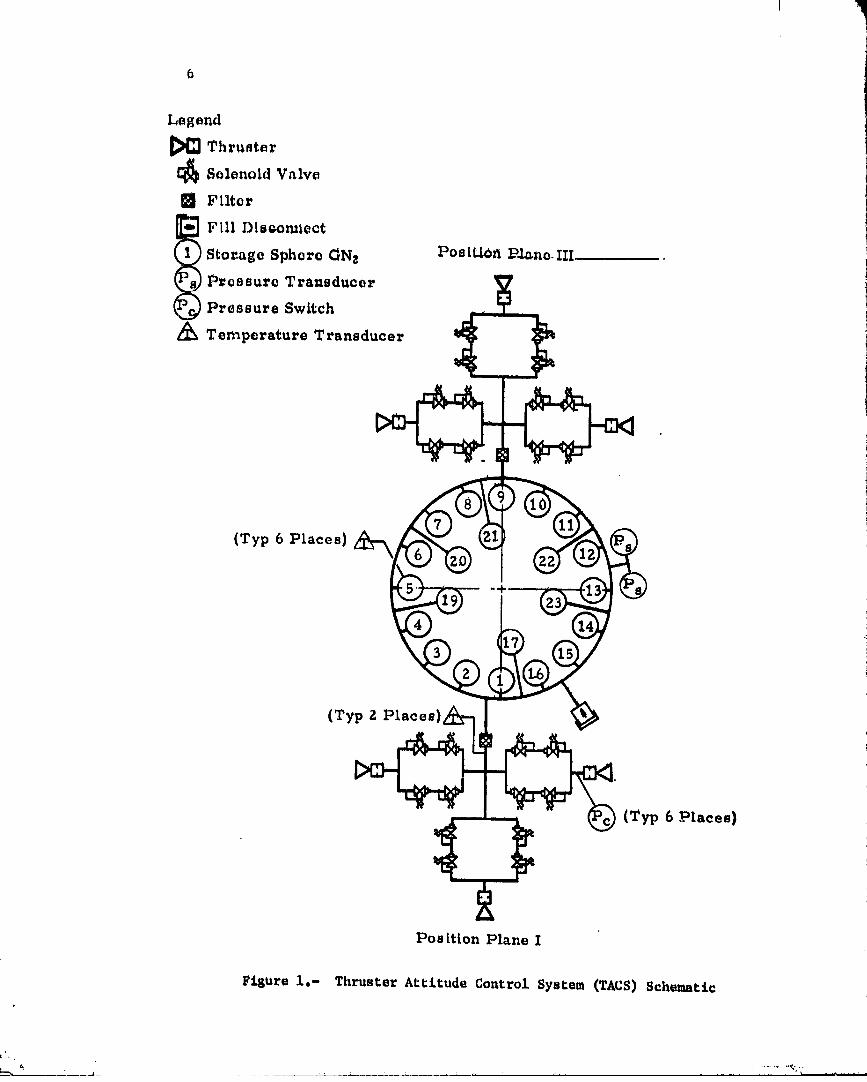
A schematic representation of the TAtS is presented in Figure i, Thelocation of th_ _yste_ on tl_e Skylab spacecraft and _he mounting of keycomponents are shown in _ig_res 2, 3, and _, The detailed ogera_Lng_mcacter_stics of each component described below are presented _.,tAppendlx A,
Th_s are 24 propellant control valve_ (F_g_:'_ _) in "'. system,four per thruster mani£Olded together tr_t_ro'.i_._,Les-para\lel redundancy.The solenoid actuated, pneumatically-op_t valve contains a small pilotpOppet integral and coaxial with the ms2, poppet. The pilot poppet controlspressure forces that. open the main poppet. Th_.pi_ot poppet and main poppetare linked meehani_ally sO that energizing the solenoid coil opens thevalve against the springs at low suppl_ pressures. When the solenoid isdqener_Lzed, both EOppets a_e pressure-unbalaficed closed to ensure leak-tight sealing.
The six thruster nozzles (Eigure 6) have 50:1 expansion ratios andhell-shaped expansion contours. These features were se£ected to maximizeSpecific impulse while confining the exhaust plume tO mlni_ze Inpingemanton the vehicle aft skirt. An impingement shield is provided to eliminateunbalanced forces on the vehicle caused by plume impingement on aft skirtstructural elements.
The 22 N2 supply storage spheres (Figure 7) in the system are of thesame design as those used in the S-_VB ambient He repres_urization system.They are constructed of welded titanium hemlspheres, and are q_alifiedfor operating pressures up to 2.206 x lO 7 N/m2 (3200 psig). The storagespheres are loaded through a self-sealin_ discnnnect (_igure 8) mountedat the vehicle skin. The disconnect was hard-capped prior to laufichtoprovide redundant sealing protection against ga_-leakage,
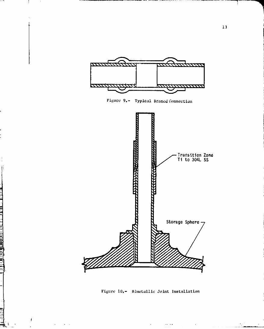
The propellant supply and distribution system is induction brazed atall tubing connect points (Figure 9) to minkmize leakage. Fluxlessinduction brazing provided a lightweight leakproof Joint, A modificationto the inlet fitting of each sphere and the addition of a bimetal Joint(Figure 10) provide the capability of "in-place" brazing of the supplyfeed line to the distribution manifold and the sphere temperature
'- '-,-,=_u PA_: BLA_K NOT FILk_ED
O000000i-TSA 14.
Legend
Thruster
[_ Solenoid V_Ive
Filter
F[ll D|seomlect
Stor.age Sphere ONz Postt_otl P_no.III
P_cssurc Transducer
Pressure Switch
Z_ Temperature Transducer
(Typ 6 Places}
(Typ 2 Places},
(Typ 6 Places)
PosLt[on Plane I
Fisure 1,- Thruster Attitude Control System (TACS) Schematic
00000001-TSB01

Thrustor
Control System
Figure 2.- Skylab Cluster Configuration
/
00000001-TSB02

q
_v_eteoroLd
Shield i1I
Figure 3.- Storage Sphere Installation
oooooo0;l_TsBo3 _

!|
lld,ePna I View
Extcrnal View
PitchThruster
Roll/Yaw
Thruster
lHume
In _p Ing e m e ntShield
Figure 4.- 'i:l_ruuter Hodalc hmtallaL[on
V
00000001-TSB04

I_ ..... !..
10
Figure 5.- Thruster Solenoid Control Valve
00000001-TSB05

11
i
i
Figure 6.- Tllruster Nozzle
Figure 7.- GN2 Storage 8pheru
f
_1 _' IIII I _m ,", " I " I llll II I I IIII I I '" " _ _ _" -
00000001-TSB06

12
Ground Loading Confisuratlon
Flight Configuration !
. Figure 8,- Fill and Drain Disconnect i
00000001-TSB07
. ,,_7 r
J
i
Figure 9.- Typlcal B_az_dConn_ct£on
Transi.tionZoneTi to 304L SS
i;
StorageSphere
Figure IO.- Bimetalllc Joint Installat£o_l
I
00000001-TSB08

Ins_rumonCaCloa, The pcopcllan_ di_Ibutlon _y,_om Includes 24 £1oxlblc
me_al tubing _o_tlozm (Figure 11) to provldc fo_ relatlve motion betweenthe ",hock" mounted--thruster modulo pancl_ and _ho hard wounted diatribu-
tlon mant£old. The two aupply I£n_ £il;:o_:a(F_uro 12) located a_ theinlet to each cluster of throe modules u_.llizo a multilayor o_ched-di_k--
construction to provlde a lO-mlcron__nom£_.1 f_ItQrin_ caR_bll _
Instrum_ntation was provided for system loading, c_ckOut, and £11gl_t
monitotin_. Two pressure transducers (Figure 13) loaat_d on the distribu-
tion manifold were provided to monitor system pressure, A third pressuretransducer was provided for ground mo_itor£t_ but not used durln8 _heflight. Six temperature tr_educe_s (Figure 14) located in six storage
spheres equally spa_ed o_ tt_ aft vehicl_ support Structure were providedto dete_mine the average bulk ga_ temperature. A t_peratu_e tra_sduce__as located at the inlet to each cluster of three modules at positionplmtes I and _. Six pressure switches (Figure 15), one for eaelt thruster,prcqlded.-a positive indication of thruster firings.
2.2 PItEFLIGI{TTEST AND CItECKOLrl:._IISTORY
The TACE was certified-for flight after successfal completion Ofdevelopme_._, qualification, and checkout test programs. This effort included
development and qualification _ag£s of the solenoid control va5%_, the in-
line gas filter, the fiLL-drain disconnect, the storage sphere, the bimetal_oin_ the manifolding, the temperature transducer, the pressure transducer,
and the pressure switch. The primary test obJecti_es, ma_or p_oblem areas,and Solutions a_e su_mmrized in this section.
2.2.1 Thruster Module Asse_l,ly Development and Qualification T_st Programs
Development test program.- The _u_pose of the d_velopment test programfor the thruster module assembly was to evaluate and establish a productibn
configuration for the TACS solenoid _alve. The development valves weretested at the valve, dual valve, and module levels to evaluate the valves' i
functional, performance, and dynamic characteristics at various environ-- Imental m".d system operating _onditions.
SeVeral different main poppet seal materials and configurations were ,,evaluated in the initial phase of testit_g. The configuration thatdemonstrated minimum leakage _ates over t.he operating pressure range was ':a conical poppet with a conical sealing surface using DuPont_s "Vespel'*as the seal material, Also, the preload on the main poppet springs wasincreased and all machined parts were ch_nically deburred to furtherenhance the leakage characteristics.
Testing of this configuration revealed that the upstream valves didnot seal effectively with a high inlet pressure and l_w AP across the
valve. All valves exhibited sufficient sealing characteristics at moderate
' O0000001-TSB09

' 1
inLcrnal Cros_ SOctiOLl Viow
Eii i ....
External View
Figure ii.- Flexible IletalTubi_ig
_'1 I_B1 o o o _--.........l,x'-x..,_.. ..........................
Figure 12.- GN2 Filter
O0000001-TSBIO

16
i"
r:_--::'::--:___ .........._
Figure 13.- PressureTransdvcer
Figure 14.- Temperature Transducer

t7
or high AP with Ra_ trapped downntroam of _lm valw_ and wore lank _lBht
wan solved by ma_ntatning tim proper hP a_rona oa_h up,troam valve durbaropera,Ion, Thl.nwan ac.oomp_iHhodby romow_1 of _ho goner dJ.odoIn _hova_vo'_ vol_ago _upprocmlon _r-cuJ._which increased _ho _loalnR tlmo of_ho downstream valw_, _lluH_oworlnB _ho _rappod pro,Huro bo_woon the valves,
Durln8 high tomporaturo _ootlnS, ulocta._Icalahort_ dovoZopo_t i_. _1_omagnum aolonold coi_ wi_o. Thla was cot.rottedby chancing tim _oiL w£rato conatan_an and changing the _nau.ta_ionfrom teflon _o poly_aldo. Aloe,this wire was wrapped on an aluminum spool, and the entire assembly waspot_ed to providu great.or hual_l_aipn_.ion.
A problu_ with bent pZunsur flanges was identified in ¢1_ downstreamvalves, /malysis rdvualud Chat prose,re sttgSes from the upstream valvescaused the plm_geg flm_ge to impact tha ori£icu pZa_a, t_us yielding theplunger, floats. This resulted in slow pruaumatic rgsponao within thevalve, A main poppet stop was incorporated in all production valves whicl_precluded impact of tile plunger flmxge with t|u-_ o_ifice pl_te.
Testing also ruvcalad thc existence _f a leak patl_ behind thO lip sualretainer which tended to slow tile valve's openilig response. Tim cause of ]tits
problem was associated witlt gas leakage into the Solenoid chamber., 1A '*Vespel" static seal was added behind the lip seal retainer.. AI_0, the Iplunger vent holes were increased from two to four_ and microZube lubricantwas applied to the lip seal to further enhance the response characteristics
: o_ the valve.
Lose of voltage suppression was encountered du_ing testing which iwas associated with failure o£ the diodes in t/revoltage suppression Icircuit. This was solved by changing to high reliability diodes from anew supplier.
During vibration tests of a module assembly it was determined thatthe valve main poppets were experiencing high dynamic loads an& wereactually t_Iseat_.ng(cl_atterinS)at a frequency which might cause damage tothe poppet seals mid seats. To r#aduce tile loads on the valve poppets duringvibration, "shock" moutttawere installed between the thruster valve panelsand the vehicle aft skirt. Because the-"shock" mounting introduced _oredegrees of freedom of movement between the valve panels mid the distributionmanifold, additlonal flexible metal tubing sections were required.
quallfleatlon test program.- _he purpose of the qualification testprogram for the thruster module assembly was to establish the flight _worthiness
of the solenoid valve, module, and cluster (three modules). !The pressure switches, temperature transducer, filter, flexible metal tubes, i
and manifold were included in the test specimen, i
1]
i
O0000001-TSB12

Durln_ proqualifl_a_ion prodnction a_o_ptanco toots at-_ho modulo],ovol, an upstream wd.vo developed a bLow*nB leakage, fluboflquon_ din=aoflombly _ovoalfld tha_ the main poppo_ neat wan fragmented with large_ofimafl_n mion_,nfi, _x_onolvo toots at simulated pr_duction ascap,ante I;Ontconditions _ovoalod l_llat tho volvo failura waftduo _o an in,off,oct _oot.stop, Tile lnJ, o_ manifold wan improperly t_L','odnanking a hIsh _ovor_oAP condition to exist', a_ronn the upstream valve, thus falling the .oa_tunder._ovoro backf_ow condlcloml. Thin Honoltlvlty _o ba_kflow waO_ocosni_od, and all auhnoquon_ Lo_ and oporatln8 procedures worn rovlowodand rowrl_ton aa roqu:t_edto onnuro tile,no vaaxo wa_ aub_octod to possible_ovoraa £1ow t:Oadi_ionn.
During vibratio_ to.tint of _ho inlet manifold installa_ion_ oonais_tn8o£ Cite £il_ar and end £1axibl. tube a_ombly restarted on a-section of the ]Mt skirt, the clamp that t,aOuntOd the filter Co the skirt yiqa.dOd. Theclamps were redesigned and the Lasts r_poated. The spocimar_ successfully matthe qualification _aquiramenta with oat additional tube clamp between the |£ili line and.figeater manifold mid the oMdltlon o[ doublers to rite _ilter !support bracket. Post-vibration tests revealed that tl_u fllte_ would notm_e_ imposed cleanliness requLecmunts, The ¢lcmtlinoss rcquLrammtts warewaived m_d no [urthe_ action was taken because the fligl_ filters hadbeen installed, and each valv_ contained an integral filter capable ofproviding protection. _rom the amount of contaminants that would be releasedby the fil_r.
quali£ico_ion testing o£ tke thruster modul_ assembly (three modules)consisted of proof_ leakage_ functiona_ vibration_ ordnance shock, dutycycling _ continuous duty, therma_ vacuum environment _ electrical, andnozzle cover blew-off tests. At the beginning of the test program, mis-handling caused the module inlet temperature transducer to beco_ inope_ative,thus _ecessltati_ the qualification 0£ this component under a separate testprogram. All p_essure switches used in the test specimen failed at varioustimes in the program. The cause of failure was determined to be diaphragmfatigue in-all cases. Further qualification testing occurred in a separatetest program. Du_ing high temperature ftmctiot_al test_ng and prior tovibration tests, a downstream valve developed a blowing leak. _he cause ofthe severe leakage was determined to b_ a fragmented seal with si_larcharacteristics to the earlier _ailure in the module production acceptancetests. Extensive testing and analytical investigation did not reveal theexact cause of failure. The most probable cause of the failure was atttlbutedto a reduction in impact and fatigue resistm_ce o£ the seal material, resultingfrom the assembly stress condition which varies randoml_ with materlalstrength propertiest manufacturing tolerances, and flow forces. The valvewas replaced and all testing was successfully completed.
Concurrent with tlm thruster module assembly qualiflcatlon tests,additional test programs were performed to investigate lip seal installationon valve operating cheracteristics, to evaluate and identify environmentaland operational conditions which might contribute to or cause the seal tofailt to establish confidence in the production seal configuration, and todevelop and evaluate backup seal configurations for use if the production i!
seal configuration had been assessed unsatisfactory for flight. :t
' I
O000000-TSB 3

19
Tim exl_cnsiw _1 fa.l.luc¢ t_l:ti_R did nol: ¢donl:lfy _.ny _poc$_$cl_cl:m_H which caused l;he.saa1_ t.o fail, In_roaa_d eonfldonce.-waa l_atn_dtn rh_ production _o_1 aottf_gurat.ion. For fll.gh_ fro_t _hin _I; program.A baakup seal wan dovolopt_d tmd _oated but_ Wa, no_ _,_p.lom_.n_ad *n_o l_h_.pr_duatt.on valve program boaauno t_ did no_ offer any known advantageover tno p_oducCion aonl_lguraClon seal.
ltoaauso of _l_e dit_fl.aultios oxporionaod with qualifying the proaauroswitch and tompo_avuro transducer in the thrustor modulo assembly quaLiFi-cacim_-_oat,program, _haso items were qttakk£koda£ the ¢omponon= levelin a separate _out proBram. _o_h components wore sub3oatod to proof,toakagu, f.unational, vibration, _hock_ burst, and cycle costin_.
Prior to _he qualification of the =omparacura transducer at the serape =neat loVal during checkout 0£ the _light _ACS, one of the modulo inlettemperature transducers was Found to have an o_t of sp_cifiaation leakf_om a weld Joln_. The magnltud_ o£ the leak did not warrant r_oval ofthe transducer; howomer, a stainless stool uclamglt_ll"doubler (Figure 16)was apoxy bonded over the body o£ all tlm t_attsducorsto preclude furtherleakage of titletype. _hu t_mperatu_e tratlsducecwith the "cla_shell"doubl_ attacl_d tO it completed all quaZi£icatlot_testing with t_oatto_aliesor deviations £_om the Cequi_e_mnts.
In thc_qualification test program the pressure switch failed to actuateduring the gost-vibratiOn cycle llfe test. The cause of failure was_termined to be a fatigue rupture o£ the stainless steel d_aphragm. Anevaluation test program was performed using pressure switches wLth Kaptondiaphragms a_d production flight pressure switches with staittlesssteeldiaphra_ms. _lm results of this program indicated that the Kaptonmaterial has a greater cycle llfe capability than the stainless steelmaterial. _owever, because of cost and sclteduleimpacts resulting fromchanging the diaphragm material and more realistic assessment o£ m_ssioncycle llfe requlrements_ the production pressure switch was consideredq_alifled at a reduced number of cycles. Also, the pressure switch talk-back parameters were not critical to mission success and the nominalmission cycle prediction was less tlmn the demonstrated cycle life of theproduction units.
2.2.2 Pressure SpltereAssembly Development and Qualification Test Programs
Development test program.- The only component in the pressure sphereassembly requiring development testing was the bimetal Joint. _te purposeof the development test program was to verify the capability of the design
: configuration to meet the Skylab mission envlronmen_ and operating require-:_ monte. Speclfi_ areas investigated were the redundancy of the Joint,
i pressure and load capabilities, weld _oint and sphere neck configuration,and tooling and welding procedures. Six test specimens were successfullytested to demonstrate tireacceptability of the bimetal Joint configuraclonfor production and flight usage.
O000000q-TSBq4

2O
! t
, , II, il --I I
d ,5
I f _
Assembly Detall of Shell
Figure 16.- Temperature T_ansducer Stainless Steel "Clamshell" Doubler
• I
" 00000001-TSCO;I

21
qual.i£1cation teat program.- ThQ purpose of the pressure sphuroassembly qualification program was _O qualify the pressure sphere instaLLa-tion £or..Skylab usage, The _est specimen included a pr_ssur_ sphereasso, mbly with temperature transducer, bimetal Joint, and a _egment of timthrust strue.r_re. The hardware was quoAi£i_d without any problems.
2,2,3 Flight System- Checkout Tests
The _llght clmckout tests o_ th_ TAGS were accompllslted at K_nnedySpace Center (KSC). Two relatively minor anomalies were t_Otod du4;ingcheckout testing. One of the sphere mounted temperature transducers fail_d
to meet the specification leakage rate requirements when checked witlt a
mass spectrometer opera£iftg in the vacuum.mode. The magnitud_ of the
leak did not Justify removal of the transducer from the system. Extensive
tests were performed to quantify the maximum leakage rn_e possible throughexisting leak paths to ensure flight worthiness. The _esults of the tests
and tl_emagnitude of the flight transducer leaka_ iRdicated that this leakage
would not be detrimental to the mission, a_d no furtlter action was required.
During _omponent inspection of backup vehicle hardware, the _ressureswitches were found to be contarainated with mercury. It was postulatedthat the fllght vehicle p_essure switches were also contaminated. Since
mercury forms an amalgam Jaith gold, _tlch is used in the braze alloy
materialp the possibility existed that the structural integrity of the ...
system might be compromised. To preclude loss of structural strength, iclamsheLL doubler assemblies were epoxy bonded over most of the braze
fittings in the area_ adjacent to the pressure switches, One fittit_g at
each thruster location was inaecesslbl_ for retrofit. Also, extensivetests were performed to evaluate the effect mercury contamination has on
the properties o£ the braze alloy used. The tests did _ot reveal any
detrimental short term effect on the strength of the brage fittings.i.
J
00000001-TSc02

23
3. THRUSTER ATT£TODE CONTROL SYSTEM MISSION SUPPORT EFFORT
This section describes the mission Support effor_ r_laClng to TACS
porformance assassmo_tt r_al-tlme problem solvln8, flight anomali_sD andthe daily system ovaluatlon.
3.1 THRUSTER ATTITUDE CONTROL SYSTEM PERFORMANCE PROGRAM
This computer program a_alyzed the performance of the TACS. The
perfor_mnce program combines logic, which describes the gas storage anddelivery parametersp ,.Ith a thruster performance program to obtain overall
system performance. Nozzle performance parameters evaluated include thrust,
specific impulse, flow rate, thrust coefficient, throat state, and exit
velocity an_ state. Also, the system parameters of total impulse and _2
mass were calculated. Input to the progra_cOnsisted of the stored GN2
pressure and temperature. Pressure los_ in transporting the _2 fromstorage sRheres to the thrusters and storage volume Varlationwith pressurewere included.
The thruster performance progra_was developed by McDonnell Douglas
Astronautics Company (MDAC). • principal feature of this progra_Is its
employment of the latest National Bureau of Standards (NBS) real gas
properties for N2. An isentropic flow process is used in the single phase
(superheat) region, and a shift is made to the homogeneous equilibrium
assumption for expanSiOns below the satu_atlon llne. Alsop a two-phaseexpansion efficiency factor is used i_ the two-phase region to account _or
the nonisentroplc phase change process.
A general description of the operation of the TACS performance programis:
1. For a given (input) storage gas temperature a_d pressure, the ma_sof gas is calculated, utilizing the real gas equation of state from
the NBS real gas properties for N2.
2. A conversion to a selected base storage gas temperature is performedholding mass coD.tent, thus provid/_g a constant base temperature for all
performance calculations, i
3, Small pressure increments are selected according to the basethermodynamic state calculated in No. 2.
4. Thruster performance and system mass calculations are made for
each pressure Incremcut_ beginning with no pressure and ending at the base
thermodynamic state. Total impulse increments are obtained by multiplying
average specific impulse by the mass increment, and a summed total ismaintained for each pressure level.
PAG BLA KNOTFILMI
" J .... 00000001-TSC03

24
5. Tim .y_tom |mrformancu parameter, a_o prLutod at each prenfluw:Low_,1. 'rhone rotmJt_ provLde a history of total tmpul.ne m_d tltruste.rperformance aa manfl l t_ expended from the barn, tlmrmodynamic tltata calculatedin No. 2.
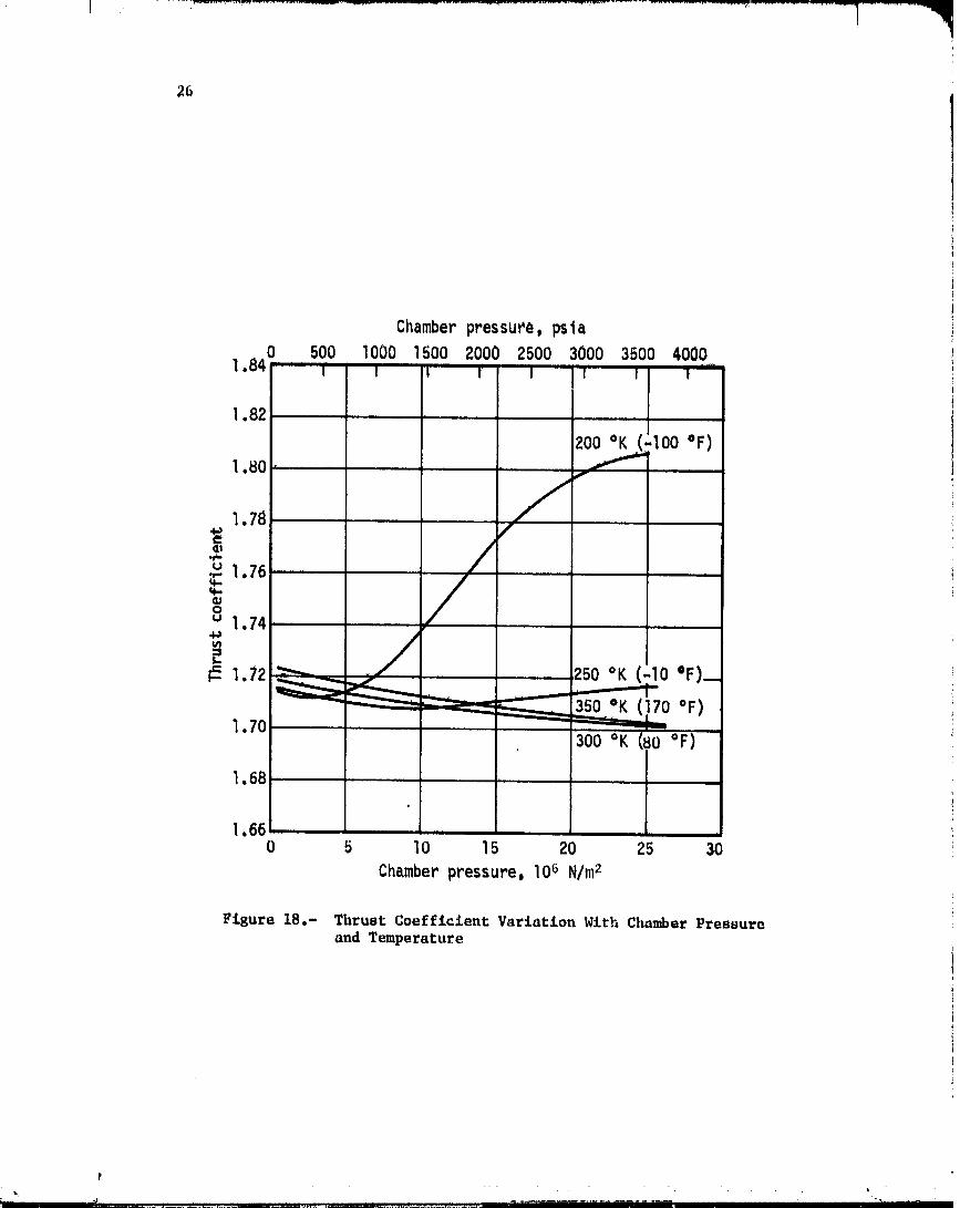
Typl,cal performance curves that Wore, gmmratod tminp thla program arepresented in Figures 17, 1,8_ 19, and 20.
3.2 SPECiFiC 1MPLILSI_ I'I,',RFOI_IANCE VERIFICATION
Preflight predictions of specific impulse were based on a detailed
analysis of real gas effects on the GNz expansion ittthe thruster nozzle.Tim analysis could not be verified since there were no data available from
tillsprogram or other sources to det_rraine the effect on performance ofcondensation in the nozzle.
During tim mission, detailed analyses of the flight momenttmt data
were performed to get an empirical assessment of the specific impulse
performa_tce. The data analyzed were li_Lted to CMG reset maneuvers with
no data dropouts, it was believed that this was the otO.y situation Inwhich the impulse imparted to the cluster could be determined accurately.
Te_x _eset maneuvers were found to be usable for this anaLy._is. ___
The flgst eight reset maneuvers mlalyzed occurred during tile Sh.2
mmmed mission. The results for these cases indicated that the appax_at
specific impulse was significantly hi,mr than had been predicted at tk_measured module inlet temperatures. Even with the estimated e=ror bm_dof over lO percent for each point (caused by effects of gravity gradient
torques, rate gyro inaccuraclea_ data sampling intervals and resolution,uncertainties in cluster mass properties, m_d mass flow rate), thespecific impulse data for some cases fell above the maximu_ preflight
predictions.
Another mmlysis of apparent specific impulse waft performed usingdata from tlleSL-3 manned nLission. Flight momentum data for two reset
maneuvers involving 80 firings were used along with thruster flow rate
data from qualification testing. Tile results of this analysis indicatethat the average specific impulse was 2 percent higher than the nominal
preflight predictions on the hot side of the vehicle and 7 percent higlmron tlle cold side of tllevehicle, based on a 70 percent two-phase ef£iciel_ey
factor. Tile estimated accuracy of tlleresults is +._ percent. It isbelieved that this tu_alysis is more accurate than the previous one becauseof tile increased performmlce stability of the astronaut installed "six-pack"
rate gyro assembly during the SL-3 maimed mlsslon. Based on these results,
use of the nominal preflight specific impulse predictions was continued fortlleduration of the mission.
00000001-TSC04

Ii.
),
p
........ ' J I I , _ i I I ............
.........._......................................... t....- J '--ZL-L--,Z"-J
00000001-TSC05
26
Chamberpressur'e, psta
1.840 500 1000 1500 200( 2500 3000 3500 4000I I I I' ! I I i .....
1.82 +
-I00OF)1.80
1.78 /
o0, / ,
•_ 1.76
1.70 _ 350 °K (170 °F)300 °K (80 °F)
1.68*
1.660 5 10 15 20 25 30
Chamberpressure,106N/m2
Figure 18.- Thrust Coe£flcient Variation With ChamberPressureand Temperature
t
_, . ........ k,
00000001-TSC06

I
d
27
I)ceSsuc_..._psja..0 500 lO00 bOO 2.000 2500 3000 350U 4000
950 m t' m I I' t' I I- 95
900- 90
850 .....
- 85
8OO _-_ "--'-------- 80 _=" 350 °K (170 °F) "_"" 760 uU ........
,u __ • -75
•,700_ ,_c' 300 °K (80 OF) 70 _ I
e,,,,. U')
6so" _ _ - 65 ..---E
600- 250 '_K (-10 °F) -60 "oR
550 _ v_"_ -55
,oo +,[(450 200 °K -I00 °F) - 50
400 -;45400 5 0 15 20 25 30
Chamber Pressure_ I0_ N/m
Fisure19.- SpecificImpulsep70Z Two-PlmseEfficiency
00000001-TSC07

2B
4OO , 400 5 I0 5 20 25 30
t
ChamberPressure,106N/m 11
Figure20.- SpecificImpulse,50ZTwo-PhaseEfficiency
00000001-TSC08

3,3 _OLENOLD VAhVE COMPUTIgRMODEL
During d_volopmont to_tinfi of th_ thru_or modulo aH_ombly, analy_laof the t_st data revealed that whoa four valvc_ wore oparatcd In thesoriOa parallel configuration, _ha opening response of tim do_mstroamvalve8 Wa_ erratic (ace paragraph 2.2.1). The identical behavior wanobserved for two valv_ in _rtms, bu_ not in sin81_ valve operation,'rhuro£ore, a dutailcd computer, modeli_ effort f._r the four.-valw_configuration wa_: iniLi.ated,
Two potential causen of tim problem wore idont:[fiedz bonding o£ tileplunger flange and leakage behind the lip seal rotaJm_r. The m_mputermodel verified that eithar of these mechanisms ¢ouJ,d load to the anomalous
response behavior and that an omp.iricag solution oi_Jcovered in testing(delaying the opening of the upstream valve relativO to the downstream)would tend tO eliminate the problem.
The computer model simulaeed the _lectrical, mechanlcal, pneumatic,
and body fo=ces acting on tltemOV_lg parts of each valve. Real gas
properties W_e included lu determining tlm flow rates aridpressures in
the various valve compaztmer_s| and nonlinear effects of electromagneticloss_s, back EMg, and hysteresis were included ir_ the eleCtricaL portion
of the model. The meclmaical portion of the modaL-_xcluded-tile afoot
of external acceleration loads as well as slidi,%g fri6t£ow forces
affecting the mot.lea of the valve parts. An algorithm monitored andcontrolled the mechanical motion of the tl_ree mechanical parts to keep tile
motion of these parts within specified design travel l_mlts. Surfacecoefficients of restitution for hard and soft s_rfa_8 w_re inclu,_@
to simulate the dynamics of impacting valve p__ti_.
The input routine was set up tO permit i_vestlgation of the sensitivity
of valve performance to dimensions (flow passages, solenoid air gap, etc.);
operating conditions (pressure, temperature_ voltage, etc.) ; and othervariables such as friction coefficients. Selected output variables,
including pressares and currents, were plotted by the computer and used
for comparison with available test data. Other variables, including valve
stroke and valve forces, were output to give the desigt1_r a better unde_-standing of the current signature traces. CompOrlsor_ of test data with the
computer program output verified the program's effectlveness to predict
valve performance and operation. ]
3.4 THERMAL ANALYSIS UPDATE I
TAGS hardware was designed and qualified for a maximum tump_ratufeof 347 °K (165 OF). Since the solenoid control valves were critical to
system operation, valve performance or anything that might affect performancewas closely monitored. Analysis of flight data obtained during the SL-2manned mission indicated that tlm valves at Position Plane I had reached
their maximum qualification test levels during a high beta m_gle period.The premlsslon thermal analysis had ,or predicted such an occurrence and,
00000001-TSC09

30
_her_foro, an inve,_ifiatlon wa_-inltla_d to dc_ormlno th_ cause of the
dlfforonce between the analytlca.k and actual temperatures valuo_, Corro]a_ion
between the fllgh_ da_a and t_ _lytlcal pcodlction ws_ obtained bya_umlu8 tha_. the aft _klrt whi_e paln_ _olar _b_orptlvlty, _, wa_ do6radcd iby rotrorockct plume conta_Lna_ion, By va_yin_ _ from a dcaiSn value ef0.3L maxlmum to 0.34 and uslnB an actual waste tank temperature va_ue of
322 °K (120-_¥) rather than the original prediction of 300 _K (80 °F),
the _ho_mal model prcdlction_ agreed _losoly wltl_ the actual v_l_o modulo
temperatures. Pho_ogra_hs of th_ aft skirt area obtalncd by the firstcrC_ further vor/.f_d the optical degradation of these surfaces, Tile
ln_reascd _s had resulted in higher temperaeures than originally predicted.
Based or_ the above flight data corralatio_s_ predictions _or thethir_ and final manned mission. (SL-4) indicated tlmt the q ualifica_.tonm_xlmu_ temper_tureS would be exceeded du_in_ the or.blts where the vehicle
was continuously exposed to the sun during the periods Of minimum betaangle-. This could be caused by_ inc_eesed solar intensity in tile
November-January period as the eart_ approached and. receded from perihelion
a_d by further degradation of the solar absorptlvi_y# as, as the sunexposure time increased. A worst case temperature of 359 °K (204 ?F) wa_
peedlcted for the negative beta a_le periods. Maximum_ minimnm, and
nominal thermal pred/ctions for =he third faanned misSio_ time period-are
shown-in Figure 21. Actual £1ight temperature da_a are also plotted forthe Position Plane _ module inlet. The maximum temperature actually
observed was approximately 353 °K (175 *_)_ indicating that the paint did
not degrade as much as assumed in the worst case prediction.
3.5 SOLENOI_ VALVE _HERMAL TEST-PROGRAm-- 1
An analysis of tltebasi_ valve design was performed to assess the
valve's capability to withstand the high temperatures predlcted.for the
final _anned mission (see paragraph 3._). The analysis included evaluationof clearances between moving parts, electrical cha_acte_istics_ material
properties of the valve _omponents, and areas of concern relative tO valve
operation at elevated temperatures. Although the analysis did not _e-veal
any d_flnite problems, the interaction of individually insignificantgeometric changes in the valve Was considered to have potential effects
which might adversely affect valve operation. As a _esult_ a test program
was initiated to verify valve operational integrity at elevated temperatures.
The objective of the test program was to determine the effects of theelevated temperatures on valve response t_m_s and leakage characteristics
at environmental conditions predicted for the SL-4 manned mission maximum
heat flux periods. Tests were performed on a thruster module assembly atroom temperature to establish a base line with which to compare test results
from other test phases. The tests performed were electrical, proof pressure,external leakage, response at three pressure levels and nomin&l operating
voltage, and internal leakage prior to and after each response test for each
pressure level.
O0000001-TSCIO

t
O0000001-TSC11

d
HSgh t_mporaturo tenting wI#_conduat_d which eonnlntod of hooking the_hrunto_ modulo at approximately 369 °K (205 °F) for 2a hour.a wJ.th tg,653 x _0_ N/m_: 0.600 pH_B) lnlo_ pvonauro, During the ,oak period the tvalvon wore ay¢lod to flotormino tho_ ronponno ehara(:_ov_ntten, and internalleakage moa_u_omOnta wore taken pr_or to a_d alice each apo_lfiod numberof _yo3.oa. After t:hoayc'lln8and nook Cont.wan _o,nplot=od,t:oatsworeporformOd at room teunporaturO to provide data for compact,ran will{ the haasline data,
Additional hggh _omporaguro soak to._._wore porfo_od at aDProxlma_ely369 °g (205 =F) and a modulo inlet preaaurc of 2.068 x 10'_N/m_ (300 pSig)go simulate maximum tompe_'ature and minimum prousuro conditions tha_ mightexist near the end of the mission. This test was alas followed by roomtemperature checks for base line compariaon purposea.
Extensive analysis of tile test data indicated tllat the thruster medalsaasembly performed normally throughout all phases of the tesging. _nternalleakage maasurataant results obta/nod during tile test program were wlthi';specification requlre_nts. Tileresponse characteristics of each. valve athigh temperatures were comparable to those observed in th_ roo_ temperatur_and initial qualification test progr_1 high temparatur_ testing. All the ;ele_trlcal and pneumatic response characteristics wero withi_ speci£1Qatlonrequirements. _n view of the expedient test facility the_m_l control methodemployed_ the actual-temperature o£ each valve ra_ged from 366 "K (200 op)to 378 °g (220 °F), One noteworthy observation was current fluctuationsthat were recorded during both room temperature and high temperaturetesting. Similar anomalies were also observed during the initial qualifica.tion testing. Based on an analysis of the data_ the current fluctuationswere not related to the thermal conditions. The rapid current changei=tdiuatesthat the valve poppet moved toward the closed position momentarilyand then _eturned to a full open position. This movement of the valvepoppet did not manifest itself in a change in thruster chamber p_essure_.and consequently module performance was unaffected.
3.6 ALTERNATI_S TO PRIRILUDE_OLENOID VALVE THERMAL PROBLF2_8
Concurrent with .he TA¢S valve thermal test program which is discussedin paragraph 3.5, a study of options or means for avoiding the high valvetemperatures was initiated. The objective of the study was to establishthe most feasible means to protect the valves from high temperature exposurein the event the valve testing revealed that temperature related problemsexisted. The options were divided into those which avoided the use of thevalves during the high temperature periods a_d those which reduced thevalve temperature. The options are summarized in the following paragraphs,
Based on a November ii SL-4 la_mch date, and assuming that tileAttitudeand Pointing Control System (APCS) was operating properly, tileTAtS wasonly needed for CMG momentum relief. Operational _ailure modes could beavoided by inhibiting the thruster System during the high temperatureperiods. Thls plan could have impacted nominal flight plan activities by

33
_dtmlba_inB m,nouvor_ ou_ of _olar inertial, oILm_r_nB _xtravoh_eularA_v_ry (_VA) and mlnlm_inB wnC d_,_urban_o_ and momentum dump Inhlbi_B.B._au_. _hO thcu_or. By,tom would be required for docktns, Inl_.1.hi_tn_._hothru_corA durln_ rJ1o h£_h _ompora_uro por_od would noco_a_ato a l_mn_hdo.L_yuntil more a_cop_ablo _ond_iona were pr_on_. Thu_ a launch delaywa_ a poaalblo option.
I£ _on_In8 revealed a hiBh temperature failure could o_eur, oven if_,ho valvoa were no_ o_ora_o¢, aovaral mo_ho_ of theft sh_oldln8 wereinvasciSatod. Throe of 01oae motltodeinvolved the _row physiaallymodifying _ a_ru_uro around _h¢ ?osltiot_ Piano I thruster nosslos. Timnecessary hardware and procedures would have boon developed on the _roundand flowu up with the crow. Tlmso options wcrel
i. A sheet metal shlold which would be attached to the aft skirta_ound the thrustor valves. Weight and vo_u_ for. CSH stowage weredisadvantaBes.
2. Appllcatlo_ of a thermal paint usln8 either an aerosol can, brush,or clOtlt. Technique o£ application was the biggest disadvantage.
3. Application of aluminized tape to the aft skirt area around thevalves. Adhering characteristics wsxe unknm_.
Two other concepts ware suggested. The first was to control valvetemperature to an acceptable level by maintainlng a pitch attitude similarto that used during SL-I. This method would impact syste_ usage for CMGmo_ntum relief and _le temperature of other cluster components. Thefinal concept relied on the use of the N2 gas supply to cool the hot valves.Since the average bulk gas temperature would be about 294 °K (70 °F) atminimum beta angles, a series of pulses-generated by COmmanding smallattitude _euvors would all0_ this relatively cool gas to lower the valve
temperature. High gas usage was a major concern with this method.
Of all the alternatives considered, the installation of the sheetmetal heat shield by the crew appeared to be the best, However. followingcompletion of the valve |_tghtemperature testing, a detailed _eview ofdata showed no indication of abnormal system perfo_nanee. Consequently.no hardware or mission changes were made. and the TAG8 completed theSkylab program suc_essfuliy.
3,7 SUPPLEMENTALSYSTEMS STUDIES
The excessively high consumption of TAtS propellant. G_. during theearly part of the Skylab mission, prompted _he initlation of studies ofmethods for either resupplying or supplementing the cold gas system.Various concepts were evaluated in an effort to determine the most feasiblemethod of resupply/supple,_ant. Certain candidate concepts. _tich arelisted below, required extensive EVA and additional systems _xd componenthardware to be carried up in subsequent Skylab launches:
00000001-TSC13

_4
Mothodi - C_rry up a roaupplymodule on SL_, _r_n.formodulo _oOrbStalWorkshop(OWe)aft .klrtand connectto tho TACS fill llno.
M_thod 2 - (Jerryup a _o_upplymodu1(_on _h-4, loavo modu10 in O_M,and connc_ _o TACitfill llnc un_n_ a long high pressure ho_o.
Mo_hod 3 - (Jonno_ onboard _xporimcu_ _a. (ONe,,)_anka on Ai_lo_kModulo (AM) _o TAGS usln8 a loflg high pro,rmro ho,o,
Method 4 - 8amo a, Me,hods l, 2, or 3 oxcop_ ho_o would be co_.nocted_o th_ pi_ch thrustor, and 8as back£1owed throu811 _he thr.u,tor valvoa.
Method 5 - Same as Mot.hod 3 except onboard ON:, f_rom b2t _.anks would beused,
Method 6 - Install a_ adjustable thrust_r in the -Z axis Scientific
Airlock (SAL) and utilLze 02 or N: from AM tanks.
Method 7 - Load additional propellan£s and use th_ CSM attitude
control propulsion system as a supRlemental OWS attitude control system.
Method 8 - Carry up an N2 resupply in a cryogenic state and include
systems for gasifying and transferrin 8 to the TACS.
Method 6 was selected as the bast concept for supplementation based
primarily on_ use of excess onboard consumables, no requirement for EVA,minimum hardware requirements, and minimal crew training and installationtime.
Initially, the thruster assembly design included provisions £o= use
of both 02 and N2 gas suRplies located in the AM. Further detaile_
ana/.y_is of the desigr, reve_led potential p_oblems associated with com-
patibility of certain lubricants and seal materials with the 02, As a_esult, subsequent design and test activities concentrated on the N2system.
The maximum total impulse ".d thrust level obtainable with the 8AL
thruste_ assembly was 151,240 N-see (34,000 ibf-sec) and 53.4 N (12 ibf),
respectively. Using a rotatable thrust_r concept, the thruster assembly
could be used to supplement the TACS during the EREP experiments and fordesaturating the CMG_s in attitudes wh_re the gravity gradient dumpscheme was not available.
t
The thruster assembly and the installation through the SAL ar_ shown
in Figure 22, which depicts the major components of the system. Maximumutilization of onboard hardware is illustrated in that only the thruster,
i valve assembly, boom assembly, and certain quick disconnects ".ere to becarried up. All other hardware including the N2 supply unit, experiment
canister, and the water hose _ere onboard the OWS. I
,,w..
, :c_ "1 I fl I I|I_l'll
O0000001-TSC14

BoomAssembly
Manually iOperated ,:Valve
!
Thruster Experiment ;Canister
VehlcleExternalSkin
Yll_ure 22,- ,qcl_.ntlflcAlrlock Thruster Systom Sche),latlc
00000001-TSD01

36
Opl_r_il;lon of tlil_ tllrutttor al-IHombiy wtnild roqllll'l_ lilaUUa.[ actulition oftilt: wllve by tile aHtronaut for a prodoto, rmtut,d period of time, dopendinp,oil the impulse rc_qulrcmout. A disk iml,tcau_r pt_rmlttod ori¢*n_atlon of tilenozzle to the dosll'od ailgttlar po_tlt'ioll to provide unc ollpJ.od torqutm abouttile roll I pitch, and yaw axes. {ustal, latlon ill" Lilt' thrustor a_liteliibly usedproctldltrds sllailar to those required for bill ollboard c.xperlmt;nl;.
Vtartficatlou tOsttntl 01: tilt; Ilardwaro lllcllided per[ornlallce agt_optallcOtesting of tile valve and tile thruster a_sombly, 0;, eompatibilityi iliad
. lubricant tests. 'rilehand operated ball valve was identical to that tidedol_bcard tileOWS in tLm focal dryer system. The higher operating pressur_
and increased cycle requirements for tilethruster assembly application of
tilevalv0 required that proof, leak, functional, cycle llfe, and bursttests be conducted to verify the valve integrity.
Mmckalp hardwaro was-delivered to Johnson Space Center (JSC) for usein crew training exorcises and flight llardwaru was delivered to KSC prior
to tileSL-3 launch. A systems status assessment of the _CS prior to the
launch, and tile more urgenk need for otller hardware items to be supplied
to the workshop resulted in a decision not to use the. SAL thrust_r
assembly during tile remalnd_r of tileSkylab mission.
3.8 MISSION SUPPORT
TileMission Support Team for tileTACS mantled tileHuntsville Operations
Support Center (Hose) 24 hours per day, 7 days per week during SL-1, SL-2,SL-3, and SL-4. For tileulmaannetLmissions on-call personnel were available
24 hours per day, 7 days per week. A daily status report was submitted
every day of tlm mission from tilelaunch of the Skylab Cluster to completionof the APes engineering tests at tlieend of the mission. With the
exception of the SL-I and SL-2 missions, each status report was coordinated
with JSC mission support personn_l wheuever the system was active.
Prior to tileSkylab mission, tileperformance of tileTACS was analyzed
, and tliecurves were generated using tlie GN2 performance computer program
, (see paragraph 3.1). Thes_ curves were used to determine the performance
of tile system during tile mission, using real time telemetry data.
TIleJSC TACS consumable status was generated by a llewlett-Packard
computer program using real ti_e data. Tile programts perforraance equations
were mathematical curve fits of the performance curves generated at tileMarsllall Space FlightCenter (bISFC) prior to start of tliemission. TheHewlett-Packard computer's limited data storage capability required tlie
use of compact equations. One obvious disadvantage of this method of
computing tilesystem status is tile error introduced by use of tile curvefit equations; however, tile error was normally less than 3 percent.
'I%wo methods were used to estimate total impulse remaining. One Methodwas based on GN;,mass calculations using telemetry real time data. Basically,
this method employed the curves generated [rom tileGN, performallce computer
' . . . .- • ,...------ --, ,.. • ......
00000001-TSD02

!; ' !
!17
p1"oFW;1111oi" il¢luil| |y uilod I I.o t'o111|ultor proFffilm Ill ¢;lltutilte 11111mlalld lol;l.l-
ilupulrlo ro111aL11Llll_ ;It ilpploprl;IIe I Imetl dul'tn)_ the I_iI1111[oII. The l,ltI01'
,ipp1"oa_'h wall I-iw, lllotlt a_vut'ale lllottlod I o det_-_1'mLne li .v111.olu ill atuil. The
other method ul l.ll;'.od I:he mLtliilllilll Impulllo blt (l, Llll) tuld willl very utwluLIoi" _I qt11-_k d0tern1|11aI I.on el t111puLilo tmalW. 'I'111.ti luethod wai_ bmlt, d ou
otlt L11mtlt11,l tllt, t:oLal hllpltli1_ per tllrullte1: I L1"lug luld 111ult tpl.ylng tlIItl by
tllt, ntmlbor of fl1.1ullSo 'rho It_la,L lillpulm, pal. ill'lug wml calculated by thet,qu_iI I ou
I,L, ,, F,t ,, (t + ,St.)' Vb,
wllore
1,L, ,,, total tmpul:.,
b_avg - ave, rage thrul;t
t = ¢,onlnlattd pulnt, wtdLli
At _ timO faotor added [o a¢couiit l'or I hrutlt t;liLotf.
The thrust level wlts dt:tt_itilLilod fl'otli Lilt' pe, l'fot'in;ltit'e t;tit'Veit ils il lllitetf.otl
el flight syl:ltelli pi'otttlure lilld av,_,rago, iaodulO iltlet tompt_raturo, The
eotimiattd-pulse width wan ch,itigty, l p_rlodlcaliy as a Luilet, lOtl o1_ the lqill
roqu,lred. The t|truiil.- tat]off Lime. wan varied t'roill 2'i to 1,0 lllttO.c, tktrLlll I tilt.
final lllllaltle,d mil4_lioii-in all a.LLomp{ to pl'ovide bet t,_r col"-relatiotl btltlieeilthe tilB aild tiuis_ mt;thodtl of _:alculatitig total-impulse relilaiti_tlg, Colllpltrl.soil
of total £nipuls_ remaluitig values cotltpl, tti2d treat tit,, etid of tke mi.ss£oli by
the different me.khod8 tudicated that a 15 inset' t_ii Ioff fat:for mol't _ ¢.Lllsoayapproximated the actttal Jlnpttl.se expended.
Several probiemtl were etieoulitered durLitg t|te mitlsLon ttttpport phat_e.
One problem was Llie intttrumentatlon trandduoer tioitle (set_ paragraph 3-.9)that occurred during ,uimlud mtsttions, 'rite tioilte was of a sttl_ficiotit ratldtll.i
tl_lture that ttvt_.ragiiig lilrgt_ 11ttttlbers Of data pohlts cl'eated lit) diffJt'ulLioi¢ t
lllld the retluits wore ¢oilvltsti,nI. eiloltgii tit Lit, |leilefii'lal. A st, eolid |_robloii,l ilvolved apparetit exei_,ttt_ tliatls ltotit#umptioli wlieu per flit'mint1 illattl_ tal,:ltlatiotil;
tu_ilodiately after large sy_ttellt utlagO. 'l'ke itidicated ma.<;_t of tiN, re maitittii;teuded to ittertmso with time until a stable eotidlt:ioti _as reached Iutd
repeatable rOtattlt_ obtaLiit:d. 'rhl, phenomenon wit8 as_ociittod with tileexlStellCe at temperature gradietlts within each sphere (l_t., paragraph 3.10)
ttlid was taken into itc¢otitit whetl aplilytng tilt,, luatll_ caXculilttOU remlltt_
to system total impulse retliahiing do, ternlinations, Finally, the nonrt;dl
t, ime data were of limited usefttltietttl to the mil4tttotl support efforl;. TileAll Digital Data 'rape (AI)IIT) event data (thrustor prettsut't: switch aetuatlotis)
were tot) noisy to It_lie beeu el ;lily practical belief It. The Htssion
Operations P I,annl.ng ,qyt4tem (_lOl',q) _ttorod and prt,eemti,+d data in a centrallyLocated ,:ompttt,!l: which wa_ llc, et_sited throttgk t-ciliate ii, rmitillitt, lltiriiig tilt,
early part tit tile tittuttLoll, t hel4o data were of ltalttted uttefttittet4tt betattst,
they were not usually available or weru erroneou_t. Ilowever, during the
latter part of tile mtt_sLon tilt; data were there consistently available ;tlld
;It't'Ui'iltO. III this tNIfil' It ,lid i_rovlde a meailtllgl-tiL ttupi_Le_,nt l:o tilt,
veal t Lint, d_lI a 14yl41:t,lli.
O0000001-TSDO3

J_
3.9 PIO_6SUNJ_'I'IL/LNSDUCERNOI_,SE
Tllt_ I:e_,t_lllt_Lry tlytltt_ll| pl.'t_,tlHurl_ illt_,altu|'tHlleHll.It Wt_lre obtlervod to fluctttate
by aH much all 4..L31' x 10" N/m? (60 pHl tl) )trot airier thP, SL-3 CSM doekla_gon Dlty of Year {])OY) 209. 'i'ho flttctutltlom_ weft, not. tiered duritag theprqvlous orbit_tl Htowagc plume o£ tile t1_tt_,:tt,u. Although the nmasuremOnts/'Olaalned within syatt,m toierat,eo_;, aa inve_,tigat:lot_ wi|t! matlt_ to dctor_Lne -tht_ probable cause of the noise.
Review of data from I)OY 208 through DOY 21o iutllt, atod _hat the dataon two different multlp.Lexers and t:helr rt,.t_pt, cttvt, reference channels werestable until tile mauned phase. When tile Skylab wat_ mantled, thert_ was anotieeabl_ increase in noise for the subject pre,_.,mrt: measurements mad theirrespective multiplexer reference channels. 'rhree other reference chamtolswere evaluated and they also showed Increa.,,ednoise content. Since the
presence of the CSM with its asso, ,ted electronic equipment may havecaused the configuration of the rad_., frequency florid to have chatlgtudfollowlng docking, the most probable cause [or the fluctuations was that
the signal flues were experiencing rad:lo frequency interference.
Tl_e fluctuations of both pressure measurements continued O_roughou_the manned phases of the mission, llowever, accurate m_ms calculatlons couldstill be made by averaging marly data points to remove th_ resides fluctuations
caused by the nols_. No further investigation or tr_ub.lesllootlng ofinsttumentatlon system was necessary.
3. i0 SPHERE TEMPERATURE ANOMALIES
It was noted during the mission support effort that mass calculations
did not stabilize until some period of time after large gas usages. After
equilibrium conditions were restored, the mass calculations yieldedconsistent resultS, ba_ analygls of flight data was performed to determinepossible means of ellminatlt_g this phenomenon from future missions and toevaluate its effect.
Calculations of the Raleigh Number indicated conduction to be the
dominant heat transfer mode in tilestorage sphere since body forces actingon the gas were small except for brief periods when gas was being withdrawn.
In most instances the rate of withdrawal of gas from the spheres _a_d the
rate of change of the radiation _nvi_onment were small enough that heat
transfer by conduction could maintain a state of near equilibrium between
th_ gas and the metal sphere, llowever, during periods of large usage,
the gas expansion tended to cause the gas to cool faster thtm the sphere_with the result that a nonequillbrium condition existed for some time
after the usage. During this transient period, large temperature gradientscould have existed within the gas.
The sphere temperature transducer installation was designed to minimizethe effect of temperature gradients within the sphere by placing the sensing
element at a point where it would read t_lo_e to the mean gas temperature in
00000001-TSD04

39
th_ sphere during tim transient parlod. Sine_ thIH moan tompo ratur_
point could shift and mL,tllod_ for analyzing its location ar_ not veryaccurat¢_, iL was tO b{_ _xpc.ctod that thor{_ would bo ,omo _rror inho.rcmtIn tim temperature data durint,, th_ transient por£oda. Fiaurea 23 and 2&show the approxi_na_e m_gnitudv of th_a error for a representative gas usage.period. The temperature during the transistor pearled read higher than itshould have baaed ot_ calculatiozls of mass from mfl_aoqucm_ equilibrium data.This trend was obscrved-durlng moat par|ode of high gas usage. Mass
calcuiatlans using pressure and t_mpc_ra_ure telemetry data p_rform_d du=_g
tht_ transient period yielded erroneous results. Thes_ tended to indicate
a greater mass usage titan that calculated from equilibrium data. i
Tl_e analysis indicated Lhat tim transducer sensing elements Sltouldhave been located slightly farther from the wall to give a better
estimate of the taean temperature during tlletransient pOrlod,
3.11 INSTRUMENTATION ERROR ANALYSIS
During tllemission, the TACS pressure required to provide a minimum
of 44.5 N (lO ibf) thrust was reassessed. To accomplish this task the
accuracy of the system instrumentation, including telemetry, had to be l
more reallstlcally determlned. I
P_elaunch loading requirements w_re based on an itmtrumentatlott error I
analysis. Individual instrumentation transducer accuracies (pressure andtemperature) were obtained from a study which evaluated all otlboard and !ground support equipment components. These accuracies were used to dev_lopa fill e_velope wh'ch guaranteed that the minimum load_d GN2 maSS would i
meet all Contract End Item Specification and mission requirements. I
During the mission, available total impulse remaining was calculated
using system pressure and bulk gas temperature. Tile usable total impulse
was obtained by subtracting an unusable amount from tlleavailablecalculated total impulse. The unusable total impulse was originally
based on a minimum system pressure required to provide 44.5 N (i0 ibf)
thrust, including instrumentation Inaccuracies.
During the second manned mission, an analysis was performed to deter-
mine whether the usable total impulse could be increased by reducing the
amount previously considered unusable. Tlteanalysis reviewed calibration
and test data for the specific pressure transducers installed in the flight
system. A 3-o error band was determined for each transducer asd then
combined with the telemetry system errors to yield a pressure readinginaccuracy of +4.688 x I0 N/m' (+68 psia). Also tile telemetry bit size
of approximately 1.034 x I0' N/m (15 psla) was included.
Using the results from tileabove analyses and tile requirement to ",provide a minimum thrust level of 44.5 N (i0 lbf) for a rescue mission
docking, the minimum allowable system pressure was lowered from 3.020 x i0_'
to 2.530 x lO t' N/m" (438 to 367 psla). This represented a gain in usable
total impuls_ of 14,283 N-see (321] Ib-sec).
0000000qTSD05

4O
--I_=_DOY224...._-_- •DOY 225 --278 ........
- 40
Gas and Spherein Equilibrium
277 ..... -With £nvironment'_---
/-- - 38GasUsage
276
-," / ; u.o / ! - 36 °
. as in ="" 275
_. // Eqilibrium=_ With Sphere
/ / -343-' , _ .... , _ l
I ----TelemetryDataI1
ii// m--Calculated Using - 32Pressureand Mass Data27 a,, J J J ,,
2 16 20 24 4 8 12 16 20Time, hr
Figure 23.- Average ON 2 Bulk Gas Temperature
"--- DOY 224 = _ DOY 225 _'i9.6
I
- 1380"_ 9.4 ........ ,_uO
9.2 ' -'1340 _,- =;
I-_' 9.C =_m u, ,= --'--"'-'-" - 1300 '_
" - 12608,(_
lZ 16 20 24 4 8 12 16 20,,. Time, hr
• Figure 24.- Average System Pressure
'. 00000001-TSD06

41
3.12 THRUST L_VKL--_:QUIREM_4TS
The premission thrust h_vol _quircment_ for the TAGS are presentedin Table I. These requiren_nts imposed a restriction on available TAGS
usable impulse, A system pressure of 2.53 x lO6 N/m ;_(367 psla) including
allowance for telemetry and instrumentation inaeeuraelea (s_e parasra4_h 3..]I)
was. required tO provldo a thrust of 4_._ N (:.0ibf). Therefore, the tot_alimpulse remaining in the TAKS when the preflsuro d_eays below 2..5/..__£0._.._m ;'(367 psla) is ky definition unusable.
SinCe the potential to gain additional ir_ulse ex=Lsted by loweringthe rescue mission thrust leve_ and, therc£ore, tile ay_tem pressure,, areview Of rescue and otl_or-mission tl_rast level rcquiremen_s was initiated-during the SL-3 mission, km analysis was per£ormed to evaluate thgustlevel requirements for various mission events utilizing available fligllt
and design-data. The results of the analysis show1% in Table 2 indicate
that a rescue mission CSM docking in tlm radial port woul_ require 44.5 N(10 kb£) w/tich would not allow the premisslon th=ust level requirementto be lowered.
C_- k . " .... k •
0000000]-TSD07

2 ........... ..
T_hle 1.- TACSPromt.nion Minimum Thrust Le_vol Roquir_monCsI i, ...........
MiSsionEv_ts Newtons Pounds-ForceL i ,l . l I | I
BoosterSeparationTrmns.ients 222.4 50
Each MannedMissionCSM Docking 89.0 20
From Last MannedMissionDocking 44.5 10to End of Mission
RescueMissionCSH Docking* 44.5. lO
*This requirementappendedto originalpremissionthrustrequirements.
_" Table 2.- TACS MinimumThrustLevel RequirementsAnalySis............ [ , , , , ,,
; MissionEvents Newtons Pounds-Forceii i .m i
Earth ResourcesExperimentPointing* 8.g 2
CM6 Reset Maneuver* 8.9 2
MomentumDesaturationManeuver* 8.9 2
Trim Burn--FourCSM Engines 89.0 20
Trim Burn--TwoCSM Engines 44.5 lO
RescueMission--NominalEnd Port 22.2-44.5 5-10Docking
ReScueMission--"WorstCase" Radial 44.5 I0PortDocking
*This thrustlevel is not optimumbut is usable. Lower thrustlevelsmight be acceptablebut were not studiedbecauseitrequiredrescalingof the slmulation.
00000001-TSD08

4_ THRUSTER ATTITUDE CONTROL SYSTI_:MDETAtLE]} M_SION EVALRATION
This suction contains tho..dt_t:atlodfli_h_ ovat_at£on of th_ TAGS.
_ho dat_ are presented by mission phase for SL-I, SL-2, orbital acoragomSL-3, orbital storage, and S6-4. The data pr_scntod for the orbital
storage pltas_S wore kept at n minimum because the TAGS was inactive.
4.1 FIRST UNtaNNeD ORBITAL STOItAtIEPERIOD, SL-I
TItsTAGS was prossurlzod for ftlght to 2.083 x lO'/N/m ;! (302£ psia)
on April 30, 1973. Approximately 047 kg (£420 1bin) of ambient tex,tperature
GN2 wo_o locdod, The 1Oadlnfl envelope showing the pre£auaeh _emperatureand pressure conditions at completion of system pressurization is presented
in Fig._r¢ 25.
Tlte Sky.tab.Cluster a_s_mbly was pZa_ed in earth orbit by a Saturn V
launch ve_Ic£e on D_y 14, £973. Lift-off occurred at 134:17:30:00 GYff.
During the boost phase Cltedual purpose micromet_orotd/heat shield was
separate4 from the vahicZe by aerodynam±c forces. Also t one o£ tltesolar
a_ray assemblies was severed from the OWS and tlm other was_prevented from
fully deploying,
The TAGS was activated at 134:17:39:52 Gbfr, at which time firingconnnands were received from the Launch Vehicle Digital Computer (LVDC)
located in the Iftstrumewt Unit (IU). The TAGS functioned as the prima_.y
attitude control system until cov.trol was transferred to the ApolloTelesdope Mount Digital Computer (ATMDC) at £34:22:20:05 GMT. At this
time the CMGts were bpin_ing up and had reached 25 percent of nominal
momentum, T|te low momentum coupled with excessive t'at_ gyro d_ift resulted
in the automatic selection of "TAGS Only" control,. Because the |teat shiekd
was severed f_om the Veiticle, th_ APCS wa_ required to maintain a "tlmtma£attitude" to keep workshop temperatures within acceptable limits. These
thet_ attitude maneuvers were performed using "TAGS Only" control, CHGcontrol was enabled with nominal momentum for the first time at
135:11t48:31 _T,
The total impulse remaining for this initial unmanned period ispresented in Figure 26, Large gas consumption on DOY's 134 and 135 resulted
from removal of orbit insertion transients and operation in a "TAGS Only"mode until transLer of control to the CMG_s was ef£ected, The total impulse
usage rate remained high because the system was required to perform frequemtCMG resets while maintaining the thermal attitude, A detailed listing of
TACS usage is presented in Appendix B,
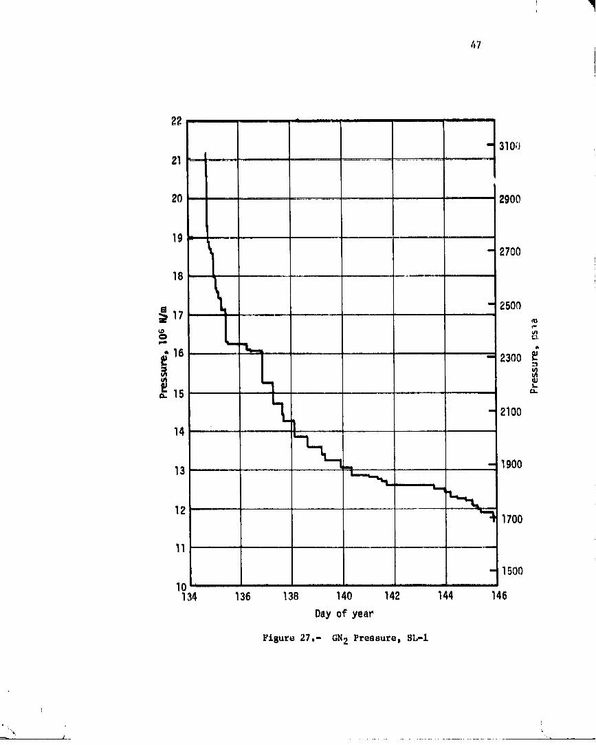
The system pressure decay and GN2 mass are shown in Figures 27 and 28.Both parameters display blowdown characteristics similar to the total impulse
remaining curve. The thrust level variation for this phase of the mission
' 00000001-TSD09

4_
Tl,mi_r_it 111-¢,, oF
50 (_0 70 8(1 90 L00 I 1024 i " I I' I "l i
_ 3400
23 ..........13300
f ,,, , , , I
Actual.FllI S"s 3ioo
- .3000ta t_
20 / 29002800,/ -19 '/
/ - 2700
18280 290 300 310 320
Average Bulk Gas Temperature, °K
Figur_ 25.- Thruster Attitude Control 8ystemGN 2 Fill Envelope
O0000001-TSDIO

45
i_ _hown in.-Figu_o29 and i_ compared co _hp thrust l_v_l _or_d in _heATMDC, Tho varla_$on in MIB (Figure 30) a1_o shows._I:.o._imo_ at wh$ch _ImATMDC conunandp_Ine width wa_ updated, With th_ exception of a.brlof
period during DOY 136 and oar_y in the mi_nlon when th_ _yn_om pr_urowa_ high,. _ho M_ wa_ mainta_nod at approximately 27 N-_ (6 lift _ec)
for aft!iciont voh_u£ar momentum manasoment. I]Yigu_es 31 and. 32 p_e_enc _tI_-and fulton firin_ hi_to_io_ darin_
A_DC control (the firin_ history _d_£1,o-on IU control Wa_ not recorded)."4
i_ A full-on ft.ring iv defined aa a firin_ of 1 s_c command pulse widthduration. Firings of longer duration are counted as individual 1 soc
full-on-firings equal co Cite number of seconds of cite firing command, i
The average bulk gas _mperatuce is prasentcd in _iguro 33. The 1average bulk gas temperatuc_ is the ar_tlmmtic _verago of the sixtemperature transducers located in oqually spaced otor_e spheres on theaft structure. The beta angle variation is shown in Figure 34. Betaar_le describes cite orientation o£ the orbital plane with respect Co thesun vector. POsiClv_ v_u_s of boca angle are defined as the o_ientationof t_e Orblt_l plane wltenthe a_p&r_nt orbital rotation o£ the spadecraftis in a clockwise direction when viewed _rom the _un. N_gative beta.angles a_e-defined by_the apparent orbital _otation o£ the spacecraft ina counterclockwise direCt.lon.'NOte thai during most of this phas_ of themlssion_ the a_erage bulk gas temperature does not inePease as is expectedwith a decrease in negative bet_.angle; this is attributable tO cooling ofthe bulk gas after o_bltal insertion. Orbital thermal equilibrium wasestablished at approximately DOY 142, thereafter the bulk gas temperatureresponded to the changes in beta angle.
The module inlet gas temperatures and the average module inlet temper-ature are presented in Figure 35, _n solar inertial attitude_ Module Oneis located on the hot side o£ the vehicle at Position Plane _ and Module T_ois located on the coi_ side o£ the vehlcle at Position Plane IIi Coolingof the hardware and gas occurred at these positions after orbital insertionuntil thermal equilibrium was established. The p_ocess was Similar _o thatoccurring in the storage spheres.
I
O0000001-TSD11

400 _" " 90
380 ....
k360 Z .... _,
• SO
.34o t ....-75_..
_20
J --'_- - 70
• 65
260Lr i , , , , ,, , ,,
• 55240..............
134 136 138 140 142 144 146
Dayof year
FiB,ure 26.- Use[bLe Total Zmpul_e RemaJ.ttJ.nSpSL-I
O0000001-TSD12
I
47
2_ "
- 310_J21 !
20 .......... 2900
9 '_" ,! i
- 27O018 .........
i - 250O
f,,,u't
0e.- line
16 _ "i - 2300'
i] "1 '-=..15 ............ =.
X - 2100
_..,. - 1900
13 ..................
'_ 1700
1 ,,,, ,, , .... i. ,, ,
- 150O
10 ..............134 136 138 140 142 144 146
Dayof year
Figure 27.- GN2 Pressure_ BL-1
I
i
00000001-TSD13

660 ............" 1450
640 i . _
" 1400
620 ....
- 1350
600 | • , _. ,, ' ...........I
- 1300
580 [ .... ,.....
. " 1250560 ..........
= tl__,R54o- ............ --12oo_=
520 .... 1150
500 ...... "1..___.._..
"I- _L_._ - 1100480 ............ "*-
'_ 1050460 ......................- I000
440 ............................
- 950
420 -' ..............._ 134 136 138 140 142 144 146
Dayof year
¥£gure 28,- I_I2 Mass, SL-1
)
ml) .- ,
- 00000001-TSD14

49
ITjightComputer-I.brustLevel,Ibf•_m---76 ........................... C;P5...............
480
............... -10S440 ...................... - O0
42O" 95
400 _I .... - go
380 I ......."-..... L_ = _ " _-: : _ 85
O
_ 360 ,-.--_ ......................!.......... -80 _
34O
l - 753201.............
_ - 7O300
-i 6s
I
260 =
240 ........ i 55140 142 144 146
134 136 138 Day of year
Ftsure 29.- 'Thrust, SL-1
e t.
;-'_-': ' - 00000001 -TSE01

5O
Pulse llidth,ms_c
r-1 _835 ,,
-4
i"
15134 136 138 140 142 144 146
Day of year
Fisure30,- NominalMinimumImpulseB$Co SL-I
00000001-TSE02

280C_
J260C ..............................................
2400 _ l j-
¢
2200 .............. _
2000 -- l1800 ............
" /'g 1600q_
1400 ........................." Ij,IE
1200 ....
1000 ../ .....
800 F ....................
600 .........
400 ................
200 ..... _ -- --
t
134 136 138 140 142 144 146
Day of year
Figure 31.- Accumulated Hintmum Lmpulse Bit Firings, SL-1
00000001-TSE03

52
4 " IF I ( f I' fi
22...... ii I iii i .11
20
]8 ,
]6 '"
_14 ..........
*-12
_ 10 .......
8 :1
..
2
,, ,, , _
134 135 138 140 142 144 146
Dayof year
F£sure 32.- Accumulated Full-On F&rinss_ SL-1
' ' _ '_.......:.............. O0000001-TSE04

53
320 -,
- 100
200 -100134 136 138 140 142 144 146
Day of year
Figure33,- AVerage(_N2 BulkGas Tempetatzlru,SL-1
0.6- 30
-0.3 _ _ - -15
-30-0.6 '
134 136 138 140 142 144 146
Day of year
Figure 34,- Beta Anglep SL-L
w
00000001-TSE05

_4
c Module 2
F-230 . j_ F-
"I -5n200 -lOf)134 136 138 140 142 144 146
Day Of year
320 , , .
- InN
290- \ .,,.. "_ - 50
o
g Average g
_- 23q ..... _- -50
200 -IO0134 136 138 40 142 144 146
Day of year
Fitlure 35,.- Module Inlet Temperatures, SI,-I
L
00000001-TSE06

55
4,2 EIRST MANN_..MISSION, SL-2 (28 DA_)
The first thrc_ ma_ _kyla_ cr_w was launched fr,,m KSC on Hay 25, 1973.Life-off occurred at 145|13t00 GMT. The CSH docked with th_ orbiting
Skylab Cluster at 146s03t40 OMT. Two EVAIs . _re performed during thisphase of the m£ssiont uric on DO¥ 158 and one on BOY 170. Grog aacomplit_h-met_Cs include deployment of Cite sunsllade and freeing 0£ the solar arrayso that it could fully duploy. CSH andocking occurred at 173t08t55 GMT.
The TAtS was utilized _xtei_s£vely durlr_ Cite first 5 days of thisIr_iCial manned plmse. TI,._ total impulse remalfling is prosen_d in
Figure 36. It can be Sets that the system usage was reduced after DOY 150
because of decreased impulse demmtds. A detailed listing of all usagefor Chls period iS presented in Appendix B.
The system pressure decay and GI|2 mass are shown in Figures 37 and 38.The thrust level variation for this phase o_ the mission iS shown in
Figure 39 and is compared tO the thrust level store& in the ADfl)C. Thevariation in MIB (_igur_ 40) also indicates the times at which the AT_)C
command pulse width was updated. The bilBwas maintained at approximately
22 N-sac (5 ibf-sec).
Figures 41 and 42 present tltrus_er firing histories for _tis missionphase. The MIB firings and full-on firings are sho_at separately. Thelarge u_ages early in the mission are associated with the stand-up EVA to
free-the partially deployed solar array and several docking attemptsbefore final hard-dock was achieved.
The average bulk gas temperature is presented in Figure 43. The betaangle varlatiOn is shown in Figure 44 for this mission phase, Note chat
the temperatures responded to the changes i_ beta angle during this period
of tlme because orbital thermal equilibrium conditions had been established,The module inlet gas temperatures and the average module inlet t-mpera_ure
are presented in Figure 45.
F • ----
........ - 00000001 -TSE07

280 ......
-60
_60 I I
i
- 55_4_0 ............
160 l
- 35
140 .....
145 150 155 160 165 170 1/5
Day of year
Figur_ 36.- Usable Total Impulse Remalnlng_ 51,-2
O0000001-TSE08

_7
12.0
- 1700
11.5 J
11.0 .......... -1600
10.5 ............
'_-. - 1500 .=
.1.0.0 ........ '_
=. ' - 14009.5 .
9.0 - 1300
e5 , r-
- 1200
8.045 150 155 160 165 170 175
Dayof year
Figure 37.- GN2 l'ressuL'op I_L-2
_:;'?::_,:-_i'_."
00000001-TSE09

51:1
500 ' - 11O0
460- 1000
440 ,,,
- 950
420 ....
- gO0 .=s
- 850380
- 8OO360 [ , ....
""z_ mmh
34O 75O
320 - 700
300 ....145 150 155 160 165 170 175
Dayof yeaP
Figure 38,- GN2 MassDSL-2
O0000001-TSEIO

Flt_tl_tComputerThrust.L_.vel, lb-f--_---------- 55 ....... "_- 41 ..............
_F ..........
290........................
- 64
280 .......- 62
270 ....... I'- 60
260 ....
s8
- 54i i i i. , i
48• .....210 _ v' - 46
20C .....14,5 150 155 160 165 170 175
Dayofyear
F£gure 39.- Thrust m SL-2
00000001-TSE 11

Pulse,.Wtdth,msec ,,.-J
so 90- -I4O
8
204
15 165 170 175145 150 155 160
Day of yea?
Flsure 40.- Nomlnal Minimum Impul.se Bit. SL-Z
J ,, , , = .,. "I I I1
O0000001-TSE12

61
6500
_J6000 F "-J
i
5500 F ,,,
5000 ,,,
4500
4000
3500 ,,
3000 ,
:.:500 ......145 150 155 160 165 !70 175
Dayof yeaP
Fisure 41,- Accumulated Minimum Zmpulse Bit Fi£1nSs_ SL-2
00000001-TSE13

_2
60
I
50
45
U'I
=='E-
40
tn
r35 [
6 ,, ,, ,
_ 20 ..............- 145 50 155 160 ;65 170 75
Dayof year
Figure42.- AccumulatedFu11-OnFirings,SL-2
00000001-TSE14

63
320 "- 100 --
t,
,.,290 ............. J= - " BO
i ' Ez6o , - o B
230 - -50 z..-
200 " -100145 150 55 160 165 170 175
Dayof year
Figure 43.- Average GN2 Bulk Gas Temper=Cure. SL-2
1.50
J - 600.75 i-
- 30=
o.oo /
_ - -30
-0.75 . -60-1.50 ...........145 "¢n 55 160 165 170 175
Day ofyear
Figure 44.- Beta AngZe, SL-2
00000001-TSF01

64
350,....I - 150320l ......
o
. 290 - '-
_'260 -A
230 "_ -J_"_--L _J% Module2
200 ...... I00145 150 IS5 160 165 170 175
bayof year320 .......
- lO0
290 ......
230 .................
- -50
200 ,, -100145 150 155 160 165 170 175
Dayof year
Fisure 45.- Module Inlet,TemperatureB, 81,-2
" ' .... 00000001-TSF02

65
4.3 SECONDUI_t4ANN_DORBI_TALSTORAGEPEILIIID
The TAC_ was inactLvetl_r0ughou_ [:he orbital_tor_geper_odfromapproximately DO¥ 173 to 209. Consequently, the total impulse remaining,the GN2 mass, the MIB firings,and the full-onflrlagswere constant,The variation in system pressure resulting from changes in bulk ga_ tem-perature with beta angle is shown in 91gure46.
The beta angle variation and the average system bulk gas temp_eratureare shOW_tin _igures47 a_d 48. Averagemodule inlet temperatureand theindividualmodule inlet temperaturesare shown in Figure49.
12.0
- 1700
11.5
11.0 - 1600
10.5
= - 1500',-
io.o i.= 1v_ _ 1400
9.5 ="
9.0 -- 1300
8.5
- 1200
8.0170 175 180 185 190 195 ZOO 205 210
Day of year
Figure 46.- SystemGN2 Pressure, Second Unmanned Phase

66
360 _
- 150
320 I I
=t _ 1.00ju-o
_'_ 50
-280 _ , , --
F- - 0_"240 ,, •
- -50
200 100170 175 180 185 lgO 195 200 205 210 |
Day of year I
Figure47.- AVerageGN2 Bulk Gas TemperaturepSecondUnmannedPhase
I " 50 .......
"_ - 60
0.75 _
- 30
g o.oo O_
e-
_ _ -30-0.75
- -60
-1.50 'J ......
170 175 180 185 190 195 200 205 210
Day of year
Figure 48.- Beta Angler Second Unmanned Phase
_:'_l l_ ...... " 'll ' _ O0000001-TSF04

360
"'"_ - 150
,,_320 _'_o -- -ModtlleI - 100_,
I-. - O_
240 ModuleZ
_-- _ - -50
200 -I00170 175 180 185 190 195 200 205 210
Day of year I360 .... I
=
- LEO l320
- ]oo_o d"
Average
_zso _" so_
- oji240
- -50
ZOO I -I00170 175 180 185 190 195 200 205 210
Day of yea_
Figure49.- M_dule Inlet Temperatures_SecondUnmannedPhase

6B
4.4 S_COND _ MISSION, SL-3 (59 DAY_)
The second three man crew Wa_ launched f_om KSC on July 28_ 1973.Lif_-off occurred at 209_llz10s50 GMT. The CSM achieved final docking
to the S_ylab C_ster at 209s19:39 OMT. Three EVA's were performedduring this mission on DOY's 218, 236D and 265. Crew achievements includedthe deployment of a sun shield over-the parasol sun shield installed by the
first craw and the installation of the rate gyro "six pack". The CSM
undocked from the Sk_ylab Cluster at 26S:19_49 GMT at the completio, ofthis mission.
The TACS total impulse remaining for this second _anned mission is
presented in.Figure 50. A detailed listing of TACS usage for this time
period is presented in Appendix B.
!
The SyStem pressure decay and GN2 mass are shown in Figures 51 and 52.The thrust level variation for this phase of the _Issio_ is shown in
Figure 53 and is compared to the th_st level stored in the ATtiC. The
variation in HIS (Figure 54) also indicates th_ times at which the ATMDC
command pulse width was updated. The MIB was maintained at approximately22 N-sec (5 ib£-sec). The MIB and full-on firing histories are shown in
Figures 55 a_d 56.
The average bulk gas temperature is presented in Figure 57. The beta----
angle variation is shown in Figure 58. The module inlet gas temperaturesand the average module inlet temperature are presented in Figure 59.
O0000001-TSF06

69
180 "" , ,
-40-
175
170- 38
U(,,)
165ul II W-
¢i3
]60 ' , - 36
°t'- E
155' , _-
F-
- 34150 ' 3_
"1_145
32
140 i
200 210 220 230 240 250 260 270
Day of year
Figure50.- UsableTotal ImpulseRemalnlngpSL-3
00000001-TSF07

7O
10.,2
10.0 1450
9.8
8.6 _"1250
8o4 r200 210 220 230 240 250 260 270
Day of year
Figure 51.- ON2 Pressurep $L-3
00000001-TSF08

71 i
340.
335 ............. -,740
" _30330 ....
-_ -/20325 iii
7'=0320
p-,,
315 m _L L . 590
310 ......
- 680-Lmm
305 ........
29( ' - i50
290200 210 220 230 240 250 260 270
Dayof year
Figure 52.- GN2 Mass, SL-3
O0000001-TSF09

72
F1tght ComputerThrust Level, lbf= 47, = _ 3cj -
210.
205. i - 46
42185
41
180200 210 220 230 240 250 260 270
Dayof ,year
Figure 53.- Thrust, SL-3
O0000001-TSFIO

73
PulseWidth,nlsec90 _ _ ..... 100-------------_--_
40 ""' .r. 9
35 ...... _ 8iI
30 "
25C_L
"" .... '_ _I
X °_"20 z
-4
5 h r ...... ,
200 210 220 230 240 250 ._60 270
Dayof year
Figure54,- Nom£naZM_nlmumImpulseB:Lt_ SL-3
I i
J
00000001-TSF11

74
7400 ' '"........
7200 -,
7000
-_800 .........
,,,t" ' "
6600 - " , ....
6400 ..... r...............
6200 ....200 210 220 230 240 250 260 270
Day of yea_ i
Figure 55o- Accumulated Minimum Zmpuls_ Bat Firings. SL-3 i
O0000001-TSF12

75
951 f
90 .........
85
0 ,,,
'F-_" 75 ,.f,.,
S.
i5 70 ......
65 .........
6Oii
55 '
200 210 P20 .230 240 250 260 Z70
Dayof year
Figure 56.- Accumulated Full-On Ftri_-l, SL-3
%
O0000001-TSF13

i
240 .-.-------- ,.-..=..-.-.__=_=_.._.--.----- -------- F,.
" -50
200 _ .------ _ ,_,,.__-100
200 210 Z20 230 ?40 250 2(J0 270Dayof year
Figure 57,- Average GN2 Bulk GaB Temperature, SL-3
1.50
O0000001-TSF14

77
360,
- 150
320 , --,_-_'__"",,'_"_'-_ 1ooModu_e 1
Module2 ,240....._ .___r"-_--'-__ aI50
200 -I00200 210 !20 230 24_) 25P 260 270
Dayof year
360 i
- 150
320- I00 ,.,-
0 0
280 Average .__ 50
-F- h-
240
- -50
20C _ -1O0200 210 220 230 240 250 260 !70
Dayof year
Figure 59.- Module inlet Temperatures, SL-3
|-'... !.
,_ t J ", • ,I
00000001-TSG01

78
4.5 THIRD U_ED ORBITALSTORAGEPERIOD
The TAGSwa_ inactive throughout. _he orbital storage period from
DOY268 to 320, The 2o_al _mpulao remaLu£ng, tho_GNp _na_S, the MIBfirings, and the full on firings were cor_tan_. The Var_ation in systempressure reaultlngfrom ohangasin bulk gas temperature wlth beta an81ais shown in Figure 60_
The beta angle variation and the average system balk gas tempara=ureare show_ in Figures 61 and 62. Aver.age module inlet temperature and theindividual module inlet temperatures are shown in Figure 63.
9.8
- 14009.6
Figure 60.- gN2 Pressure_ Third Unmanned Phase
00000001-TSG02

360'
- 150
320- lOOu.
0
i -
) -oS240 _ "_i
- -50
200 -100260 270 280 290 300 310 320 330
Dayof year
FiBure 61.- AveraBe GN2 Bulk Gas Temperature, Third Unmanned Phase
1.50
- 60
0.75
o.oo o.
_ .305-0.75 "
- -60
-1.50 ....260 270 Z80 290 300 310 320 330
Dayof year ii
Figure 62°- Beta AnBle_ Third Unmanned Phase l)
00000001-TSG03

80
360
, - 150
320 "'---.L_ _--,,_-_- _ _ -''_ _'_Module1 100 ,,=-1
240 Module2-' _ - - -50
2O0 . -100260 270 280 Z90 300 310 320 330
Dayof year360 ,, ' ,
i 150320 '
loo P
i280 -- t Average S0_
o240
- -50
zoo [ ,, -IOO26( 27C 280 290 300 310 320 330
Dayof year
Figure 63.- Module Inlet Temperatures. Third Ummm_md Phsse
00000001-TSG04

81
4.6 THII_ _',{NI_DMISSIOn, SL-4 (84 _AYS)
The third and final three maa crew wa_ launched from KSC o_ November 16,
1973, Lift-off occurred at 320s14_03 GMT with dockLng of the CSM to the
Skylab ClustoD occu_rlng at 320_21s41-GMT. Four 8VA's wer_ performed
during the mission or DOYts 326, 359, 363_ a_d 034, Comet Kohoutek sclence
was added to the mission objectives becauso the comet perihelion and
optimum viewing opportuniti_s coincided wlt_ this mission phase, Although
the Comet Kohoutek science did incre,.se the projected TACS usage , of moresignificance r_latlve to system usage was the loss o£ CMG No. 1 on DOY 326,
The CSM undocked from the Skylab Cluster at 039:10_34 GMT in Year 1974.
This completed the Skylab planned flight actlvitles.
The total impulse remaining for this third manned mission is presented
in ?igure 64° A detailed listing of TACS usage for this time period is_. p_esented in Appe_dlx B_
The system pressure decay and GN2 mass are shown, in Figures 65 and 66.The thrust level variation for this phase of the mission is shown in
Figure 67 and is compared to the thrust level _co_ed in the ATMDC° The
variation _n MIB (Figure 68) also shows the times at whlcll the ATMDC
command pulse width was updated. The MIB was maintained at approximately22 N-sac (5 lb£-Sec)° The MZ_ and full-on firing histories are shown in
Figures 69 and 70.
The average bulk 8as temperature and the beta angle variation are
ShOwn in Figures 71 and 72° The module inlet gas temperature_ and the
average module inlet temperature are presented in Figure 73.
00000001-TSG05

82
- 35
14oL--,L.'
L - 30120_-,,. ,.,.._
- 25U
100 ®U'l, _,
'- -20
8O
o_
\40 I'-l - 10
I
- 520 ....
O i
320 335 350 3_5 015 030 045
Day of year
Figure 64°- Usable Tots/ Impulse Remalningp 8L-4
• ,-_- _. -;. , ,.• . .............. . - , <
00000001-TSG06

83
9
Q - _008
7- lO00
' _'__'_ - 800_ 5 'rm
_oo=4 l-
,,,, m
- 400
- 2OO
.... ii
320 335 350 365 O15 030 045
Day of year
_Igure 65,- Gbl2 Pressure_ SL-4
00000001-TSG07

_4
300
270 L - 600---_-._.,
!24O ....
- 500
210
180 .... _' - 400
g .t50 .... _- 300 _"
120 ,,,
90 ..... 200
; t
i i
- 100
30 I '
0 " I ....320 335 350 365 015 030 045
Dayof year
Ftsure 66o- GN2 HaasDSL-4
" ' 00000001-TSG08

B5
Right ComputorT_r.ustLeveL,Ibf
2OO
180 L_ -40L..
160 -_ - 35/
L140
- 30
._'120
loo /
I - 2O
8O
- 15
60
)- 10
40320 335 350 365 015 030 045
Oa) of year !
Fisure 67.- Thrust, SL-4
1i!I
00000001-TSG09

Pulse..Wtdth, msec
35 7_=100--_ lZO-_LSOm_ 180_---_m.20_G 0
-730 ......
,, ._zo== -4.==
1 E10 " _ ....
- 2
O _
320 335 350 3GG O1G 030 045
Dayo_'year
Figure68.- HominalMinimumImpulseBit+ SL-4
Z, "_ .......... "............ ......... O0000001-TSGIO

'I,
B7
12,000 ' , , .. •
11,BOO
7,UOO ,320 335 350 365 015 030 045
Dayof year
Fisure 69.- Accumulated Minimum Impulse Bit Firinss, SL-4
O0000001-TSG11

170' '_ -- '
160i r
150
140e/t
130 r
IZO ......
110
lOG
C i i i
J20 335 350 365 015 030 045
Dayof year
Fts=te 70,- Accumulated Full-On Firlngs_ SL-4
1
00000001-TSG12

B9
360 ...............................
- I50
320 .... , ............... ...o - 1-000
A
240- -BO
20_2(_ 335 350 36,_ 015 030 045|00
Day ofyear
Figure 71,- Average GN2 Bulk Gas Temperature, SL,-4
1.50 .......
- 6O
0.75 i- 30
o //.o.oo/ ,, . • / - ..30
-o.'°j .....,,j _.,o-1.50 .......
320 335 350 365 015 030 045
Dayof year
Figure 72.- Bet_Angle_SL-4
!
.J _ -_ .... W
00000001-TSG13

9O
36O
320,, Modu ,.
0
l Moaule 2 .1p.
240 ._ .,I k I ,Ll
200 100320 335 350 365 015 030 045
DAyof year360 .............
- 150
320 " I
o_ - loo o_E Average
50
240 " '..............- -50
200 ....... 100320 335 150 365 015 030 045
Dayof year
FtBuCe73.- ModuleInlet Temperatures, SL-4
00000001-TSG14

g.1..I......
APPENDJXA.THRUSTERATTITUDECONTROLSYSTEM
COMPONENTOPERATINGCHARACTERISTICS

93
°_
f t fir I ......
,_._ ,_
N _Z_¢,,0 q-4'--.
_3 0 G_
ID' I I |Till "" "
. _•" _
,'i'_ ,I:DING PA_ BLANK NoT PLi_ED , t
00000002-TSA03


95
o_-_ , o..-.° _ _ • _, °
_-_'_- 6_ _ o ooo ®
x x x ,_ x (_ _ o x x x ?o _0 0
_ _._ • .. _ .
00000002-TSA05

96
;,i _ ,
00000002-TSA06

o ooo a _8o
ii i
i i , ,, ii I I
00000002-TSA07

APPENDIXB.THRUSTERATTITUDECONTROLSYSTEMIMPULSEUSAGE
PR_)C_:)INGPAG_ BLANK NOT _ILMED
i
00000002-TSA08

1oi
00000002-TSA09

1.02
/
00000002-TSA10

103
• 00000002-TSA11

--, 00000002-TSA12

10_
' 00000002-TSA13

106
+
" 00000002-TSA14

ZO7
O0000002-TSB01

108
O0000002-TSB02

k
!
_&__ '.
O0000002-TSB03

ii0
APPROVAL
SKYLABTHRUSTERATTITUDE-_CONTROLSYSTEM
G1e_ _.._Wilmer,Jr.
The information in this report has been _evlewed for securityclassificatlon. ReView of any inf_rmatio_ concerning Department of
Defense or A_omlc Energy COmmission proRr_ms has been made hy the MSFC
Security Classigicatlon Offica_. This _eport, _n its entirety, has Beendetermined to be unclassi£1ed.
This document has also been reviewed and approved ion technical
accuracy.
K. B_.Chandler
Chief, Auxiliary Propulsion Branch
A. A. McCool.-
Actin 8 Chief, Propulsion Division _ _ _'_
A. A. McCool Rein Ise JUL i ; Ig4Director, Structures and P_opulsion Manager, Skylab ProRram Office
Laboratory
1_ U.8. GOVERNMENT PRINTING UFFICE t974 - 640-444 / 22 REGION NO. 4