00 Engineering Graphics - Cover Pages
27
All of you have seen a tractor and its trolley/ trailer. The trolley can be easily joined or removed from the tractor as per the need. Have you ever noticed that how this trolley is joined or detached from the tractor? This work is made so simple by a joint between the tractor and the trolley using a pin or a cotter. A fork end is there at the back of the tractor and an eye end is there in front of the trolley and a round rod is inserted in between these two to make the joint. In industry also different cotter joints are used some of these we shall learn in the following paragraphs. First of all we shall learn about the cotter. Fig 4.1 A cotter is a flat rectangular cross section wedge-shaped piece or bar of mild steel block which is uniform in thickness but tapering in width on one side in general. It is used to connect rigidly two rods, whose axes are collinear and which transmit motion in the axial direction (tensile or compressive forces) without rotation. The cotter is inserted perpendicular to the axes of the shafts which are subjected to tensile forces. Cotter provides rigid joint support. COTTER: CHAPTER 4 ROD JOINTS 108 ENGINEERING GRAPHICS
Transcript of 00 Engineering Graphics - Cover Pages
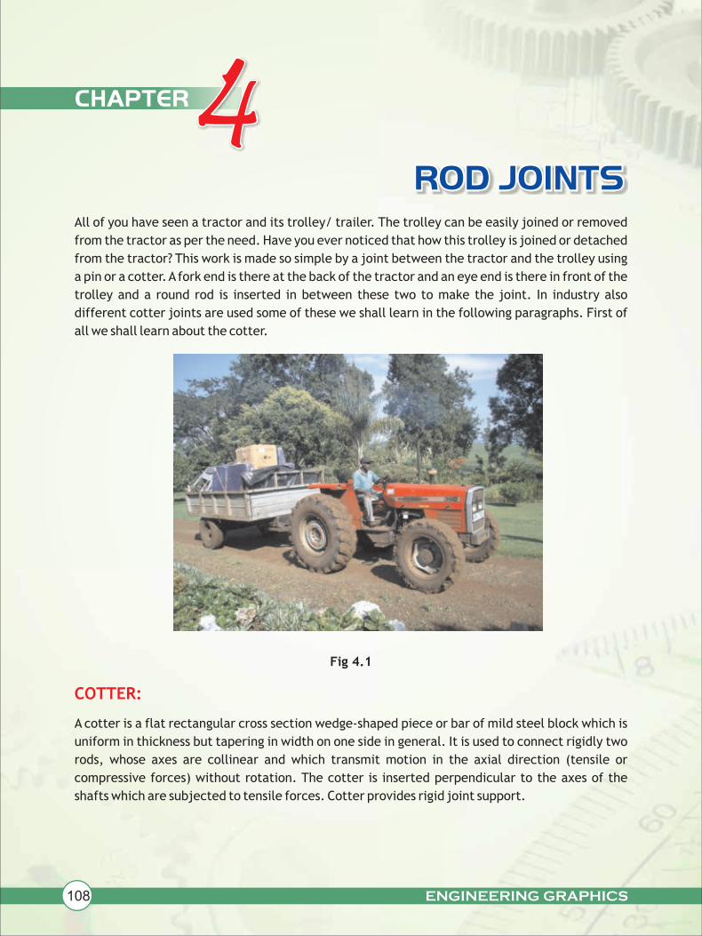
All of you have seen a tractor and its trolley/ trailer. The trolley can be easily joined or removed
from the tractor as per the need. Have you ever noticed that how this trolley is joined or detached
from the tractor? This work is made so simple by a joint between the tractor and the trolley using
a pin or a cotter. A fork end is there at the back of the tractor and an eye end is there in front of the
trolley and a round rod is inserted in between these two to make the joint. In industry also
different cotter joints are used some of these we shall learn in the following paragraphs. First of
all we shall learn about the cotter.
Fig 4.1
A cotter is a flat rectangular cross section wedge-shaped piece or bar of mild steel block which is
uniform in thickness but tapering in width on one side in general. It is used to connect rigidly two
rods, whose axes are collinear and which transmit motion in the axial direction (tensile or
compressive forces) without rotation. The cotter is inserted perpendicular to the axes of the
shafts which are subjected to tensile forces. Cotter provides rigid joint support.
COTTER:
CHAPTER 4ROD JOINTS
108 ENGINEERING GRAPHICS

ENGINEERING GRAPHICS 109
ROD JOINTS
DIMENSIONS OF A COTTER:
Let 'D' be the diameter of connecting rods.
Average dimension of the cotter (d) = 1.3D
Thickness of cotter (t) =0.3D
Length of cotter (l) = 3.5D to 4D.
Fig 4.2
These types of joints are simple in design and need very less application of tools. These are used
to connect the end of a rod of a shaft. The end of the bar has a hole in it and it is called a lug. The
shaft carries a hole. This shaft is locked in place by a smaller pin that passes through the side of
the lug and partly or completely through the shaft itself. This locking pin is named as a cotter,
which sometimes is also applied to the whole joint. The cotter joint is a temporary fastening,
which allows the assembly and disassembly of a unit without damaging the fastened elements of
connecting components. In this type of joint the parts are held together by frictional force.
The obvious example is of a bicycle where both pedal bars separately locked by a cotter pin, on
their common driving shaft having the sprocket to the wheel.
Steel is the most common material used for this application.
Typical applications of the cotter joint are fastening of piston rods and cross heads
in steam engines, yokes in rods, tool fixtures and for services of similar kinds etc.
Examples:
SHAFT
D
SIDE VIEW FRONT VIEW
TOP VIEW
COTTER
8
tTAPER 1:30 ON THIS SIDE
33
t
d
L

ENGINEERING GRAPHICS110
ROD JOINTS
USE OF COTTER JOINT
USE OF TAPER IN COTTER JOINT:
The joint is useful in the following conditions:
(i) To connect a rod directly with a machine, so as to transmit a force to the machine
through the rod or vice- versa.
(ii) When it is desired to increase the length of the rod.
(iii) To connect two rods rigidly in the direction of their length.
The taper in the cotter is provided to take the advantage of wedging action (friction locking). The
taper also keeps the joint alive even after some wear in the joint has taken place as the gap
generated due to the wear automatically filled up by the self travel of the cotter. This travel is
assisted due to the taper given in the cotter. Taper helps in insertion into the position and
withdrawal and lateral adjustment of connected parts. The taper should not be too large causing
self removal of the cotter under the external load, but if the large taper is essential, in a case
when frequent disassembly is required, locking devices such as set screw/lock pin etc. become
necessary to secure the cotter in position against the slackening or removal of the cotter from its
position. Generally, the taper of 1: 30 is given and is decided on the basis of the angle of friction
between cotter and rods material. The taper angle should not be greater than the angle of
friction. The thickness of the cotter is generally kept equal to one fourth and one fifth of its width
in the centre. The width of the slot is made 3 to 5 mm bigger than the cotter. When the cotter fits
into the slot, the central portion of the cotter comes in contact with spigot and pushes it into the
socket. These forces on the contacting surfaces prestress the joint and provide the required force
for friction locking of the bearing surfaces. Finally, the edges of the cotter and the edges of the
slot are rounded.
In our syllabus the assembly and disassembly of cotter joints for circular and square rod are there.
We shall learn that there are three cotter joints for connecting the circular rods:
a. Sleeve and Cotter joint
b. Socket and Spigot joint and
c. Knuckle joint (only sectional front view is in our syllabus).
Also in our syllabus there is only one cotter joint for joining square or rectangular rods and
it is called:
d. Gib and cotter joint.
Now, let us learn more about the Sleeve and Cotter Joint

ENGINEERING GRAPHICS 111
ROD JOINTS
SLEEVE AND COTTER JOINT:
Sleeve and cotter joint is used to connect two round rods or sometimes to connect two
pipes/tubes. The rods are forged and increased in diameter to some length just to compensate for
the loss of material, for making rectangular hole, accommodate the rectangular tapered cotter in
each rod. The ends of both the rods are chamfered to avoid burring and easy insertion in the
hollow steel sleeve (socket/cylinder/muff). Both the rods are of the same dimensions. A hollow
sleeve is passed over both the rods and has two rectangular holes for the insertion of cotter at
right angle to the axes of the rods. The cotters are automatically adjusted due to the extra margin
given for the clearance in the rod and the sleeve. The relative position of slots is such that the
driving in of the cotters tends to force the rods towards each other in socket or hollow sleeve.
When sleeve and rods are subjected to axial tensile force then the cotter is subjected to shearing
force, these joints are useful for light transmission of axial loads.
Fig 4.3
SLEEVE
COTTER
ROD B
ROD A
SLEEVE AND COTTER JOINT

ENGINEERING GRAPHICS112
ROD JOINTS
Dimensions of a Sleeve and Cotter Joint in terms of diameter of the rods (d)
Fig 4.4
Figure given below (fig : 4.5) shows the parts of a Sleeve and Cotter Joint.
Assemble the parts correctly and then draw the following views to a scale 1 : 1
(a) Front view, upper half in section.
(b) Side view, viewing from the left.
Print title and scale used. Draw the projection symbol. Give '8' important dimensions.
Question:
3.3d
CLEARANCE X,Y AND Z=3mmTAPER 1:30
3.3d 3mm
Ø2.4d
Ø1.2dØ3
.5d
.3d
1.3dd d
X
Y
1.2
d
2.4
d
TAPER ON THIS SIDE
Z
Ød
H
110 110
Ø 2
5
42 SHAFT-A SHAFT-B 42
4
Ø25
8Ø35
Ø70
110
Ø35
32
8
37
5
835
100100
35
SLEEVE WITH COTTER SLOTS
SLEEVE AND COTTER JOINTS
NOTE : FIG. NOT TO SCALE.USE DIMENSIONS GIVEN FOR DRAWING SOLUTIONS.
COTTER (2-OFF)
SLEEVE AND COTTER JOINT
H
FRONT VIEWLEFT SIDE VIEW
Fig 4.5

ENGINEERING GRAPHICS 113
ROD JOINTS
Solution of fig :
Question:
4.5
Fig: 4.6
The figure given below (fig: 4.7) shows the assembly of a Sleeve and Cotter Joint
Disassemble the following parts and draw the following views to a full size scale.
(a) F.E. of the sleeve and S.E. viewing from left.
(b) F.E. of Rod A and Rod B and S.E. viewing from left.
(c) F.E. of cotter in vertical position and the plan.
Print titles and scale used. Draw the projection of symbol. Give 8 important dimensions.
110
35 37
100 100110
Ø2
5
Ø3
5
110
Ø70
A
A
8
542
8
LEFT SIDE VIEW
32
SLEEVE AND COTTER JOINT
FRONT VIEW UPPER HALF IN SECTION (SECTION AT AA)
Fig 4.7
SCALE 1:1NOTE : ALL FILLETS AND ROUNDS : R4
SLEEVE AND COTTER JOINT ASSEMBLYFRONT VIEW FULL IN SECTION
3
32
R
50
32
3Ø 2
4
Ø24
Ø30
Ø66810
3028
90
4
90
2830
10 R
3
50
3
LEFT SIDE VIEW
A
A
TAPER 1:30

ENGINEERING GRAPHICS114
ROD JOINTS
Answer of fig 4.7
Fig 4.8
Figure given below (fig: 4.9) shows the exploded drawing of a Sleeve and Cotter
Joint. Assemble the parts correctly and then draw the following views to scale 1:1
(a) Front view full in section.
(b) Side view, viewing from the left.
Print title and scale used. Draw the projection symbol. Give '8' important dimensions.
Question:
ROD-AFRONT VIEW
100ROD-B
Ø30
L.SIDE VIEW
Ø24
A
Ø30
32
8
100
B
Ø66
Ø30
8
37
A
Ø24
Ø66
Ø30
3090
28
COTTER
FR
ON
T V
IEW
TOP VIEW
C
8
SLEEVE AND COTTER JOINT
Fig 4.9
40 100
3
8 2
100
40
Ø30
8 32
50
28 50
C
Ø24
Ø24
Ø30
30
3B
Ø66
8
3
30
Ø30
90
F
'B' IS A SLEEVE WITH SLOTS FOR COTTEREACH SLOT INCLUDES CLEARANCE=3mm.
C-COTTER
TWO SHAFTS WITH SLOTS FOR COTTERS
COTTER
10037
9030
3
90
SLEEVE WITH COTTER HOLES
35
32
A

ENGINEERING GRAPHICS 115
ROD JOINTS
Answer of fig. 4.9
Fig 4.10
Socket and Spigot Cotter Joint is
connecting two rods in such a way
that it can transfer axial
compression or tensile load. In
this case one end of the first rod is
enlarged in diameter to some
length, just to compensate the
loss of material due to rectangular
hole made in it to accommodate a
cotter. A collar is provided at the
end of the enlarged end of the
spigot. The one end of the second
rod is formed into a socket or box
having an appropriate inner
diameter to fit the spigot along
with a collar, for a very simple
construction socket can be considered as a hollow pipe having one side solid and the other hollow,
while the spigot is a solid rod, the solid spigot is nearly of the size of the internal radii of the
socket, where it can fit. Once they are fit, consider that a rectangular cavity of tapering
construction through both the parts, i.e., spigot and socket. This cavity or slot is kept slightly out
SOCKET AND SPIGOT JOINT
FRONT VIEW
332R
50
3 32
33Ø 2
4
Ø2
4
Ø30
Ø668
402890
4
902840
10R
A
FRONT VIEW FULL IN SECTION LEFT SIDE VIEW
ROD-A
SOCKET
COTTER
COLLAR-A
COLLAR-B
SPIGOT
ROD-B
SOCKET AND SPIGOT JOINTFig 4.11
50
10
SCALE 1:1
SLEEVE AND COTTER JOINT FULL IN SECTION
ATAPER 1:30

ENGINEERING GRAPHICS116
ROD JOINTS
of alignment so that driving in of the cotter tends to pull the slots in a line, thus making the joint
perfectly tight and rigid. A clearance of 2 to 3 mm is made in these joints for the proper
functioning of the cotter.
Fig 4.12
Ø1.5
dØ
2.5
d
Ø d
1.3d
3 mm gap
1 2
3
Ø1.2
d
Ø1.7
5d
Ø d
Z Y
0.4d
X
G
0.3d
SECTION AT GG3.3d-6mm
3.5
d T
O 4
d
PARALLEL
FRONT VIEW LEFT SIDE VIEW
CLEARANCE X,Y AND Z=3mm
TAPER 1:30
TOP VIEW
SOCKET AND SPIGOT JOINT
G d
RR
TAPER

ENGINEERING GRAPHICS 117
ROD JOINTS
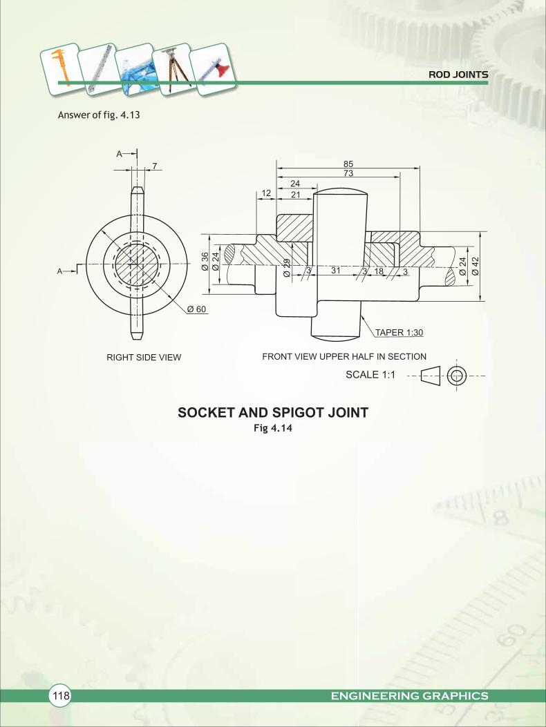
Question: The details of a socket and spigot joint are shown in fig 4.13. Assemble these parts
correctly and then draw its following views to scale full size.
(a) Front view upper half in section.
(b) Side view, as viewed from right.
Print heading and scale used. Draw projection symbol. Give six important dimensions
70
SPIGOT (1-OFF)
183418
8
84
31 TAPER 1:30
COTTER (1-OFF)
DETAILS OF A SOCKET AND SPIGOT COTTER JOINT
12
3
Ø24
Ø36
Ø29
Fig 4.13
Ø29
31
73
3
21
Ø24
Ø42
12
24
SOCKET (1-OFF)
FRONT VIEW FRONT VIEW
FRONT VIEW
ENGINEERING GRAPHICS118
ROD JOINTS
Answer of fig. 4.13
Fig 4.14
7
A8573
1224
21Ø
36
Ø 2
4
Ø 2
9
3 31 3 318 Ø 2
4
Ø 4
2
TAPER 1:30
Ø 60
RIGHT SIDE VIEW
SOCKET AND SPIGOT JOINT
FRONT VIEW UPPER HALF IN SECTION
SCALE 1:1
A

ENGINEERING GRAPHICS 119
ROD JOINTS
Exercise: The three views of a Sleeve and Cotter Joint are given. Disassemble the parts as
given below and draw the following views :
(a) SPIGOT
(i) Front view. (ii) Side view from right
(b) SOCKET
(i) Front view (ii) Right side view.
Print headings and scale used. Draw projection symbol. Give 8 important dimensions
SLEEVE AND COTTER JOINTFig 4.15
Ø 2
5
35
1225
18
3
10
30
34
3312
18
3
TAPER 1:30
Ø 4
0
10
10
Ø 6
0
Ø 2
5
FRONT VIEW
RIGHT SIDE VIEW
90
TOP VIEW
A
A
ENGINEERING GRAPHICS120
ROD JOINTS
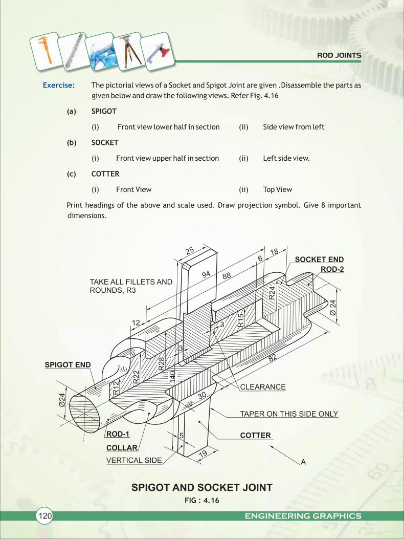
Exercise: The pictorial views of a Socket and Spigot Joint are given .Disassemble the parts as
given below and draw the following views. Refer Fig. 4.16
(a) SPIGOT
(i) Front view lower half in section (ii) Side view from left
(b) SOCKET
(i) Front view upper half in section (ii) Left side view.
(c) COTTER
(i) Front View (ii) Top View
Print headings of the above and scale used. Draw projection symbol. Give 8 important
dimensions.
SPIGOT AND SOCKET JOINT FIG : 4.16
TAKE ALL FILLETS ANDROUNDS, R3
12
25
94 88
18SOCKET END
ROD-2
Ø 2
4R24
R15
3
6
3
R2
8
R22
140
R12
Ø24
ROD-1
COLLAR
VERTICAL SIDE
SPIGOT END
30CLEARANCE
TAPER ON THIS SIDE ONLY
COTTER
A19
5
82

ENGINEERING GRAPHICS 121
ROD JOINTS
KNUCKLE JOINT OR PIN JOINT
A knuckle joint is generally used to connect rods not positioned in a straight line and subjected to
axial tensile load. This joint is not rigid. Sometimes, if it is required to be used to support
compressive loading, a guide may be provided to constrain the motion of two fastened
components (rods). In this joint the end of one rod is forged to form an eye while the other is made
in the form of a fork having double eyes and this is called as eye end and fork end respectively. Eye
end is inserted in fork end and a cylindrical pin is inserted through common holes in them. The
cylindrical pin is kept in position by a round collar through which a transverse taper pin is
inserted. The rods are quite free to rotate about the cylindrical pin. The end of the rods is made
rectangular to some distance for firm grip and then these are made into a hexagonal or octagonal
in shape (for an easy adjustment with the help of a spanner or a wrench), before it is forged into
eye and fork shapes. This type of joint is widely used in practice to connect rods, which, for
various reasons, cannot be fitted with a rigid joint. It is commonly used when a reciprocating
motion is to be converted into a rotary motion or vice-versa. This joint is used for connecting D-
slide valve, and eccentric rod of a steam engine, air brake of locomotives and many kinds of levers
and rod connections, tie bars of trusses, links of suspension chains and many other links. The
knuckle joint is also used for fastening more than two rods intersecting at a single points.
PIN 1 IN 30TAPER
Ø40
14
FORK END
COLLAR
Ø25
105
R15
1235
30
20
30
20
Ø50
90
Ø40
14
KUNCKLE PIN
EYE END
80
36
Ø50
30
30
CIRCULARPIN
KNUCKLE - JOINTASSEMBLY
EYE END
TAPER PIN
COLLARFORK END
Fig: 4.17
KNUCKLE JOINT OR PIN JOINT PARTS

ENGINEERING GRAPHICS122
ROD JOINTS
Dimensions of a Knuckle Joint or Pin Joint in terms of the diameter(d) of the rods to be
connected.
Fig: 4.18
Fig: 4.19
OCTAGONAL
R=1.2d+0.75d
R=0.75d
0.7
5d
Ødd14
.4d
0.7
dØ
1.2
d0
.7d
Ød
1.5d
0.4
d
4d
Ø1.5d
1.2d
R=1.2d
5d
R=0.6d
1.5d
KNUCKLE JOINT
Ø1
.2d
Ød
Ø1.2d
EYE END
SECTIONAL ASSEMBLY OF A KNUCKLE JOINT
PIN
EYE END
COLLAR TAPER PIN
FORK END
R = 0.75d
0.7
5d
R=d+0.75d
Ø1.5d
TAPER PIN DIA =0.25d
Ø2d
ROUND ROD-AROUND ROD-B
FORK END
COLLAR
TAPER PIN
PIN
SCALE 1:1

ENGINEERING GRAPHICS 123
ROD JOINTS
Question: fig 4.19(a) shows the parts of a KUNCKLE JOINT. Assemble the parts correctly and
then draw the front view, showing upper half in section using the scale 1:1
Print title and scale used. Give 6 important dimensions.
12
Ø 4
0Ø 24
FR
ON
T V
IEW
FO
RK
EN
D
35
R 3
3
SQ 30R
15
Ø6
0
35
18 30 18
TA
PE
R P
IN 4
4 L
ON
GØ
6 x
Ø4
CO
LL
AR14
Ø4
0
Ø2
4
Ø2
4
82
PIN
35
30
90
30
FR
ON
T V
IEW
12
0
TO
P V
IEW
EY
E E
ND
KN
UC
KL
E J
OIN
TFig
: 4.1
9(a
)
Ø2
4
SQ 30
Ø24

ENGINEERING GRAPHICS124
ROD JOINTS
Answer of fig 4.19 (a)
Ø24
35
R 3
3
R 1
5
Ø2
4
14
18
90
SQ30
18
12
Ø4
0
5
KN
UC
KL
E J
OIN
T
12
0
35
SQ30
Fig
: 4.2
0
SC
ALE
1:1

ENGINEERING GRAPHICS 125
ROD JOINTS
Question: The figure 4.21 shows the parts of a Knuckle joint. Assemble these parts correctly
and then draw the Front view, bottom half in section, to a scale full size.
Print title and scale used. Give six important dimensions.
KN
UC
KL
E-J
OIN
T
Ø4
0TA
PE
R P
IN
CO
LL
AR
(Ø
30
)2615
10
Ø315
KN
UC
KL
E P
IN Ø20 R
14
R 2
5
R14
FO
RK
EN
D R
OD
Ø30
10
Ø20
76
10Ø4
Ø40
70
Ø2
0
EY
E E
ND
RO
D
OC
TA
GO
NA
L E
ND
36
Ø20
SQ25 R14
Ø20
35
36
SQ25SQ25
36
60
Ø 20 Ø 20
Fig
: 4.2
1

ENGINEERING GRAPHICS126
ROD JOINTS
Answer of fig 4.21
SQ 25
Ø 20
35
R30
R25
R13
10
Ø3
Ø 4
0
Ø 3
5
76
35
Ø30
10
70
35
Ø 20
SQ 25
Ø 2
0
HE
LP
ING
VIE
W
FR
ON
T V
IEW
(LO
WE
R H
ALF
IN
SE
CT
ION
)
SC
AL
E 1
:1
KN
UC
KL
E J
OIN
TFig
: 4.2
2
Ø4

ENGINEERING GRAPHICS 127
ROD JOINTS
Exercises: The three views of a Knuckle Joint are given in (fig.4.23). Disassemble and draw
the parts as given below.
(a) FORK END
(i) Front view upper half in section
(b) EYE END
(i) Front view lower half in section
(c) CIRCULAR PIN
(i) FRONT VIEW
Print headings of the above views and scale used. Draw projection symbol. Give six
important dimensions
Fig 4.23
18
12
8
28
18
12
Ø 38
Ø 32
15
R15
R 30
28
R12
44
Ø2
5
Ø 38
Ø 25
R12
100
Ø 6
130
SCALE 1:1
Ø2
5
44
FRONT VIEW FULL IN SECTION
TOP VIEW
Ø 3
ASSEMBLY OF KNUCKLE JOINT

ENGINEERING GRAPHICS128
ROD JOINTS
GIB AND COTTER JOINT
This joint is used to join two rods of square or rectangular in cross section. The end of one rod is
forged in the from of a fork or strap. The height of the other rod is increased for compensating the
loss of material in making the slot for cotter. The Gib is made up of mild steel and has the same
thickness as that of the cotter. the Gib has projections at the top and bottom ends which act like
hooks. While connecting two rods the Gib is inserted first and pushed towards the end of the fork
and then the cotter is hammered over. The tapering sides of the Gib and the cotter mate with
each other, while their outer sides are parallel to each and perpendicular to the common axis of
the rods. Hence, when a Gib is used with a cotter, the opposite faces of the slots in the rods are
parallel to each other. The Gib acts like a counter part of the socket/strap. The Gib increases the
tearing area of the cotter and prevents slackening of the joint besides holding the jaws of the
strap or fork from opening wide when the cotter is inserted. The use of Gib and Cotter enables the
parallel holes to be used. When Gib is used the taper is provided in the Gib. This joint is useful to
fasten connecting rod of a steam engine or marine engine.
Fig. 4.25
COTTER
FORK
SECTIONAL VIEW OF GIB AND COTTER JOINT
ROD END
TAPER ONTHIS SIDE
COTTER
RECTANGULARSLOT
GIB
Fig. 4.24
FORK END
GIB
FORK END
EYE END

ENGINEERING GRAPHICS 129
ROD JOINTS
Dimensions of a Gib and Cotter Joint in terms of the side (s) of the rods to be connected.
Fig. 4.26
The figure 4.27 shows the exploded pictorial View of a Gib and Cotter Joint.
Assemble these parts correctly and then draw the following views to scale 1:1.
(a) Front View, full in section
(b) Right side view
(c) Top view.
Print title and scale used. Give six important dimensions.
Question:
FRONT VIEW FULL IN SECTION
GIB AND COTTER JOINT FOR SQUARE RODS
0.3
6B
SQ
S
B/4
Z
L M
EYE ENDGIB
A B
COTTER
C D
X
2S
SQ
S
A=C=D=0.75SB=1.3SL=0.55BM=0.45B
H
L=
3.5
S
SQ
S
0.3S
Y = 3mm
CLEARANCE X,Y AND Z = 3mmTAPER 1:20
Fig : 4.27
FORK END
H
LEFT SIDE VIEW
TOP VIEW
A
B30
35
10
112
SQ30
R5
20
10
10
35
27
30F
R5
SQ30
50
C
53
20 12
53
50
10
76
10
TAPER ON THIS SIDE
10
DETAILS OF GIB AND COTTER JOINT

ENGINEERING GRAPHICS130
ROD JOINTS
Answer: of fig (4.27)
Fig. 4.28
The figure 4.29 shows the detail drawings of different parts of a Gib and Cotter
Joint for joining two square rods. Assemble all the parts correctly and draw the
following views to scale 1:1
(a) Front view, upper half in section.
(b) Side view, viewing from the left hand side.
(c) Print title, scale used and draw the projection symbol. Give '6' important
dimensions.
Question:
10
30
TOP VIEW
RIGHT SIDE VIEW FRONT VIEW FULL IN SECTION
20 30
112
53
Taper
10
53
3
1220
10
76
10
B
C 30 X
10
SQ
30
A. 3X
ASSEMBLY OF A GIB AND COTTER JOINT
SCALE 1:1
A
A

ENGINEERING GRAPHICS 131
ROD JOINTS
DETAILS OF A GIB AND COTTER JOINT
FIG: 4.29
SQ
40
SQ
40
3855
FRONT VIEW
EYE END
10
TOP VIEWSQ. ROD
42 55 35
162
R10
SQ
40
FORK ENDFRONT VIEW
13
40
13
SQ
40
FORK TOP VIEW
TOP VIEW OF COTTER
10
TOP VIEW OF GIB
12
96
66 26
COTTER
GIB
15
0
32
FRONT VIEW
26

ENGINEERING GRAPHICS132
ROD JOINTS
Answer of fig 4.29
FIG
: 4.3
0
32
12
15
26
26
R10
SQ40
66
TA
PE
R 1
:30
HA
LF
SE
CT
ION
AL F
RO
NT
VIE
W
40
A
10
LE
FT
SID
E V
IEW
3
3
SQ40
SC
ALE
1:1
A
AS
SE
MB
LY
OF
A G
IB A
ND
CO
TT
ER

ENGINEERING GRAPHICS 133
ROD JOINTS
Exercise: The two views of a Gib and Cotter Joint are given. Disassemble the parts as give
below: Fig : 4.31
(a) FORK END
(i) Front view upper half in section and top view without section.
(b) EYE END
(i) Front lower half in section and top view.
(c) GIB
(i) Front view and top view
(d) COTTER
(i) Front and top view.
Print headings of the above views and scale used. Draw projection symbol. Give six
important dimensions.
28
14 3
3 22 22 41
12
SQ
40
12
100
152
SQ
40
GIB AND COTTER JOINT Fig 4.31
12
FRONT VIEW UPPER HALF IN SECTION
TOP VIEW
TAPER 1:30

ENGINEERING GRAPHICS134
ROD JOINTS
Exercises
Q.1. What is cotter?
Q.2. What are dimensions of a cotter in terms of the diameter of the shafts to be joined?
Q.3. Why clearance is necessary in a cotter joint?
Q.4. What do you understand by the self locking of the cotter?
Q.5. Why a Gib is used along with a cotter in a Gib and cotter joint?
Q.6. Where knuckle joint is used?