
0 KISSsoft Tutorial: Bolt selection and rating according ... / 8 2 Calculation of a flanged...
8
1 / 8 23. Oktober 2008 KISSsoft Tutorial: Bolt selection and rating according to VDI guideline 2230 __________________________________________________________________________________________ For release 10/2008 kisssoft-tut-004-E-bolts.doc Last modification 23.10.2008 16:48:00 __________________________________________________________________________________________ 1 Starting KISSsoft 1.1 Starting the software Start KISSsoft using Start/Program Files/KISSsoft 10-2008/KISSsoft. The following window will appear: Figure 1.1-1: Start KISSsoft, KISSsoft main window. 1.2 Select Calculation Using the Module tree window Tab Modules, select the bolt analysis: Figure 1.2-1: Selecting Calculation Module Bolts. KISSsoft Tutorial 004: Bolt selection and rating according to VDI guideline 2230
Transcript of 0 KISSsoft Tutorial: Bolt selection and rating according ... / 8 2 Calculation of a flanged...
1 / 8 23. Oktober 2008
KISSsoft Tutorial:
Bolt selection and rating according to VDI guideline 2230
__________________________________________________________________________________________ For release 10/2008
kisssoft-tut-004-E-bolts.doc Last modification 23.10.2008 16:48:00 __________________________________________________________________________________________
1 Starting KISSsoft
1.1 Starting the software
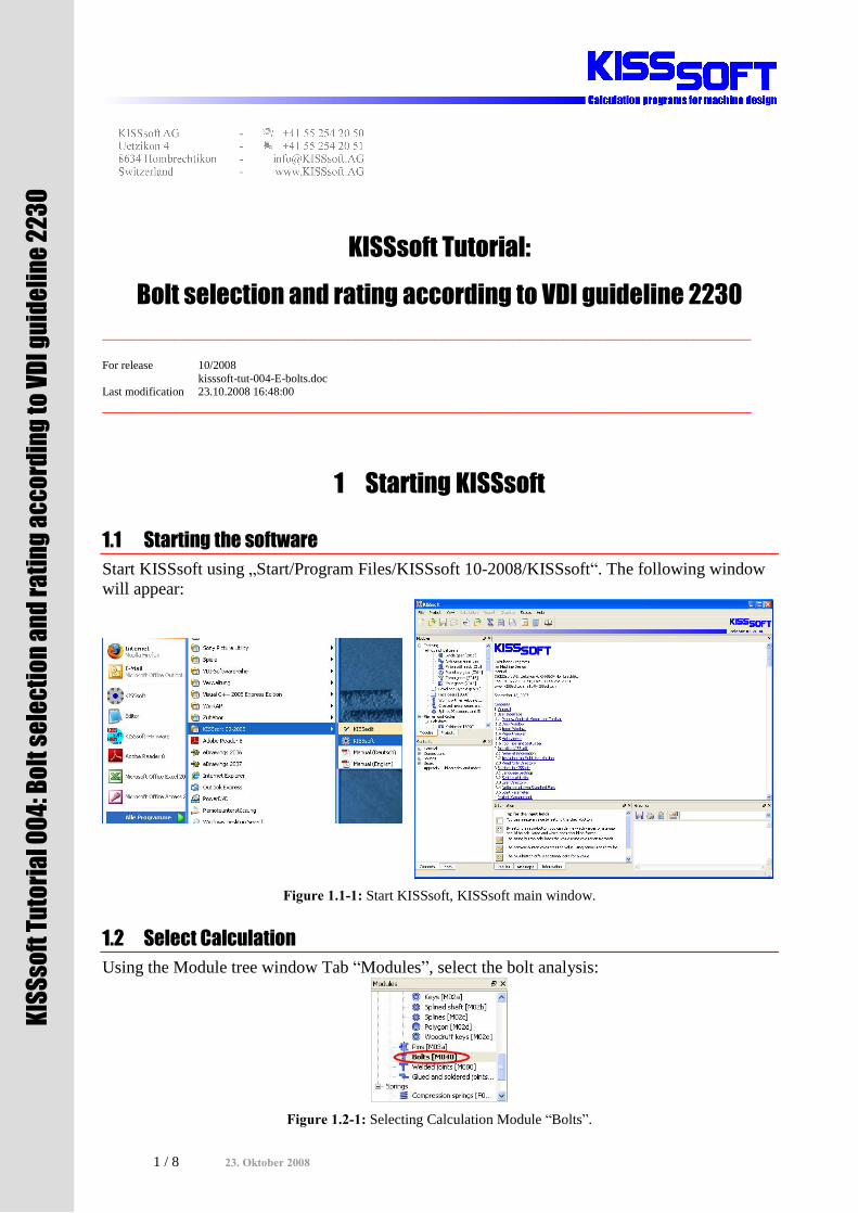
Start KISSsoft using �Start/Program Files/KISSsoft 10-2008/KISSsoft�. The following window will appear:
Figure 1.1-1: Start KISSsoft, KISSsoft main window.
1.2 Select Calculation
Using the Module tree window Tab �Modules�, select the bolt analysis:
Figure 1.2-1: Selecting Calculation Module �Bolts�.
KIS
Ss
oft
Tu
tori
al
00
4: B
olt
se
lec
tio
n a
nd
ra
tin
g a
cc
ord
ing
to
VD
I g
uid
eli
ne
22
30
2 / 8
2 Calculation of a flanged connection
2.1 Task description
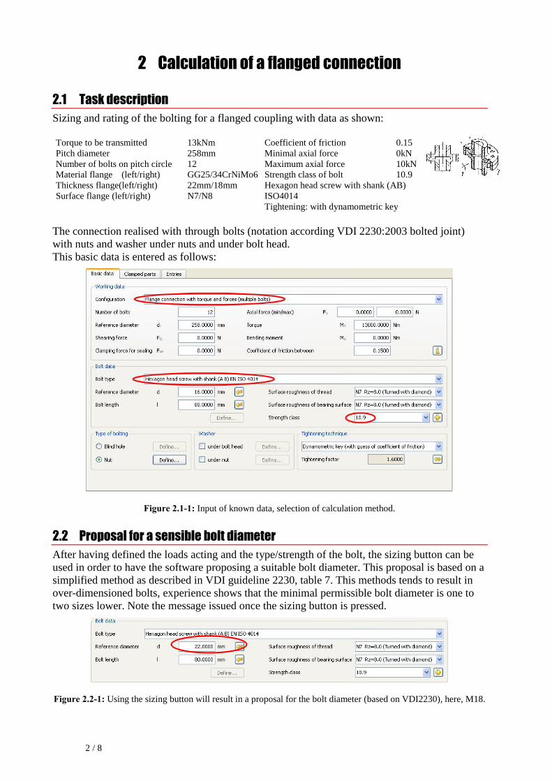
Sizing and rating of the bolting for a flanged coupling with data as shown: Torque to be transmitted 13kNm Pitch diameter 258mm Number of bolts on pitch circle 12 Material flange (left/right) GG25/34CrNiMo6 Thickness flange(left/right) 22mm/18mm Surface flange (left/right) N7/N8
Coefficient of friction 0.15 Minimal axial force 0kN Maximum axial force 10kN Strength class of bolt 10.9 Hexagon head screw with shank (AB) ISO4014 Tightening: with dynamometric key
The connection realised with through bolts (notation according VDI 2230:2003 bolted joint) with nuts and washer under nuts and under bolt head. This basic data is entered as follows:
Figure 2.1-1: Input of known data, selection of calculation method.
2.2 Proposal for a sensible bolt diameter
After having defined the loads acting and the type/strength of the bolt, the sizing button can be used in order to have the software proposing a suitable bolt diameter. This proposal is based on a simplified method as described in VDI guideline 2230, table 7. This methods tends to result in over-dimensioned bolts, experience shows that the minimal permissible bolt diameter is one to two sizes lower. Note the message issued once the sizing button is pressed.
Figure 2.2-1: Using the sizing button will result in a proposal for the bolt diameter (based on VDI2230), here, M18.
3 / 8
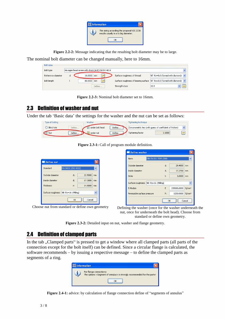
Figure 2.2-2: Message indicating that the resulting bolt diameter may be to large.
The nominal bolt diameter can be changed manually, here to 16mm.
Figure 2.2-3: Nominal bolt diameter set to 16mm.
2.3 Definition of washer and nut
Under the tab �Basic data� the settings for the washer and the nut can be set as follows:
Figure 2.3-1: Call of program module definition.
Choose nut from standard or define own geometry
Defining the washer (once for the washer underneath the nut, once for underneath the bolt head). Choose from
standard or define own geometry.
Figure 2.3-2: Detailed input on nut, washer and flange geometry.
2.4 Definition of clamped parts
In the tab �Clamped parts� is pressed to get a window where all clamped parts (all parts of the connection except for the bolt itself) can be defined. Since a circular flange is calculated, the software recommends � by issuing a respective message � to define the clamped parts as segments of a ring.
Figure 2.4-1: advice: by calculation of flange connection define of �segments of annulus�
4 / 8
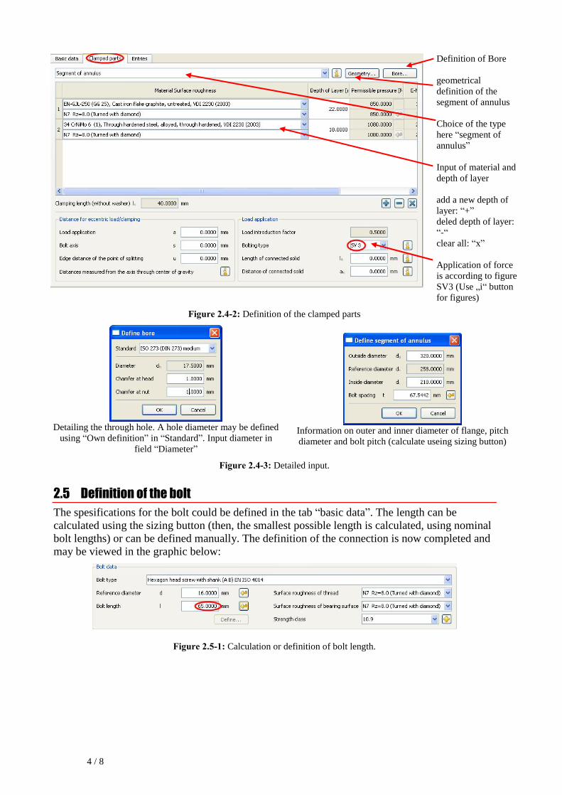
Definition of Bore geometrical definition of the segment of annulus Choice of the type here �segment of annulus� Input of material and depth of layer add a new depth of layer: �+� deled depth of layer: �-� clear all: �x� Application of force is according to figure SV3 (Use �i� button for figures)
Figure 2.4-2: Definition of the clamped parts
Detailing the through hole. A hole diameter may be defined
using �Own definition� in �Standard�. Input diameter in field �Diameter�
Information on outer and inner diameter of flange, pitch diameter and bolt pitch (calculate useing sizing button)
Figure 2.4-3: Detailed input.
2.5 Definition of the bolt
The spesifications for the bolt could be defined in the tab �basic data�. The length can be calculated using the sizing button (then, the smallest possible length is calculated, using nominal bolt lengths) or can be defined manually. The definition of the connection is now completed and may be viewed in the graphic below:
Figure 2.5-1: Calculation or definition of bolt length.
5 / 8
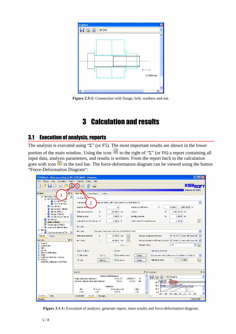
Figure 2.5-2: Connection with flange, bolt, washers and nut.
3 Calculation and results
3.1 Execution of analysis, reports
The analysis is executed using �Ó� (or F5). The most important results are shown in the lower
portion of the main window. Using the icon to the right of �Ó� (or F6) a report containing all input data, analysis parameters, and results is written. From the report back to the calculation goes with icon in the tool bar. The force-deformation diagram can be viewed using the button �Force-Deformation Diagram�:
Figure 3.1-1: Execution of analysis, generate report, main results and force-deformation diagram.
2
1
6 / 8
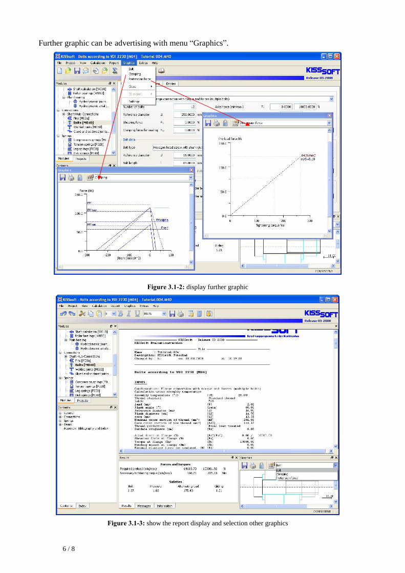
Further graphic can be advertising with menu �Graphics�.
Figure 3.1-2: display further graphic
Figure 3.1-3: show the report display and selection other graphics
7 / 8
3.2 Comments on the results generated
Results shown in the main window: Preload force (N), alphaA=1, alphaA eff
The required mounting pre-tension such that the connection will withstand the loads. A minimal value (tightening factor=1) and a maximum value (tightening factor=1.6 in this example) are shown.
tightening torque (Nm), alphaA=1, alphaA eff
Information on the achieved tightening torque. A minimal value (tightening factor=1) and a maximum value (tightening factor=1.6 in this example) are shown.
Safeties bolt Safety factor against yield point Safeties pressure minimal Safety of surface pressure Safeties Alternating load Safety factor against fatigue of screw Results shown in the report, �Calculating safeties with the maximal required mounting pretension force: Mounting-Pretensionforce (N) [FM]
Besides the required pre-tension (see table above), in the report, the nominal pre-tension according to VDI2230 is shown. This value is higher than the maximum value of the required mounting pre-tension.
Tightening torque (Nm) [MA]
In the report, the nominal pre-tension according to VDI2230 is shown.
4 Further calculations
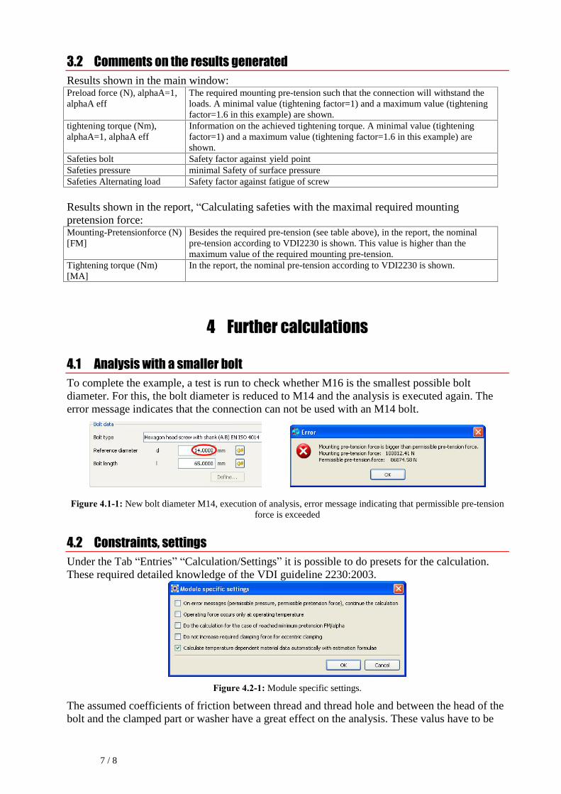
4.1 Analysis with a smaller bolt
To complete the example, a test is run to check whether M16 is the smallest possible bolt diameter. For this, the bolt diameter is reduced to M14 and the analysis is executed again. The error message indicates that the connection can not be used with an M14 bolt.
Figure 4.1-1: New bolt diameter M14, execution of analysis, error message indicating that permissible pre-tension force is exceeded
4.2 Constraints, settings
Under the Tab �Entries� �Calculation/Settings� it is possible to do presets for the calculation. These required detailed knowledge of the VDI guideline 2230:2003.
Figure 4.2-1: Module specific settings.
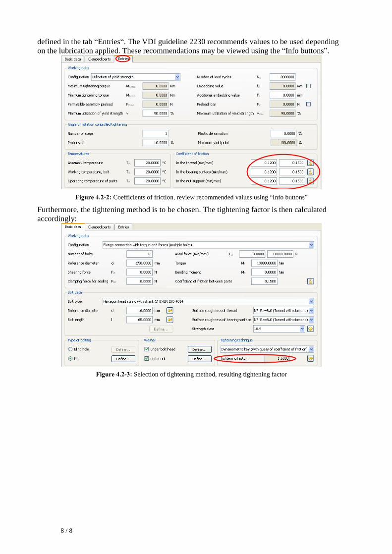
The assumed coefficients of friction between thread and thread hole and between the head of the bolt and the clamped part or washer have a great effect on the analysis. These valus have to be
8 / 8
defined in the tab �Entries�. The VDI guideline 2230 recommends values to be used depending on the lubrication applied. These recommendations may be viewed using the �Info buttons�.
Figure 4.2-2: Coefficients of friction, review recommended values using �Info buttons�
Furthermore, the tightening method is to be chosen. The tightening factor is then calculated accordingly:
Figure 4.2-3: Selection of tightening method, resulting tightening factor


