0 Introduction Nokia
17
1 © 2006 Nokia 0-Introductionn.ppt / 29 Oct 2006 / ACr Company Confidential Introductory Flexi EDGE BTS Training
-
Upload
rezabachtiar -
Category
Documents
-
view
248 -
download
6
description
NOKIA BTS RADIO
Transcript of 0 Introduction Nokia

1 © 2006 Nokia 0-Introductionn.ppt / 29 Oct 2006 / ACr
Company Confidential
Introductory
Flexi EDGE BTS
Training

2 © 2006 Nokia 0-Introductionn.ppt / 29 Oct 2006 / ACr
Company Confidential
Contents of the training
• Overall training Objectives
• Introduction to the Nokia Flexi EDGE BTS
• Architecture
• Modules (units) in detail
• Typical Configuration examples
• Software overview – features and compatibility
• Nokia Flexi EDGE BTS Manager
• Summary

3 © 2006 Nokia 0-Introductionn.ppt / 29 Oct 2006 / ACr
Company Confidential
Objectives
On completion of this course, the students can:
• Describe the benefits of Flexi EDGE Basestation
• Name the required and optional modules, and explain their functions
• Explain the major differences between Nokia Flexi EDGE BTS and Nokia UltraSite BTS
• Describe some typical configurations of Flexi EDGE
• Explain the main stages of the commissioning process

4 © 2006 Nokia 0-Introductionn.ppt / 29 Oct 2006 / ACr
Company Confidential
Introduction to the
Nokia Flexi EDGE BTSProduct overview

5 © 2006 Nokia 0-Introductionn.ppt / 29 Oct 2006 / ACr
Company Confidential
Introduction to Flexi EDGE BTS
On completion of this module the students will be able to:
• Explain the need for a new platform
• Describe the concept of Flexi EDGE BTS
• List the hardware differences between the current Nokia UltraSite BTS and the new Nokia Flexi EDGE BTS

6 © 2006 Nokia 0-Introductionn.ppt / 29 Oct 2006 / ACr
Company Confidential
Why a new platform?
1. FIERCE PRICE COMPETITION, GROSS MARGINS UNDER HUGE PRESSURE
• Produce a new platform having a clearly lower cost base• Substantial UltraSite cost reductions not easy nor cheap to achieve
2. MODERNISATION AND VENDOR EXITS OPEN UP POSSIBILITIES FOR MARKET SHARE EXPANSION
• Increased market share with a new, differentiated offering• Instead of PIUs, design self-supporting (mechanically) compatible with Flexi
WCDMA
• Supports a wider range of site types with reduction of OPEX (when in stacks) and IMPEX (enables new ways to build sites)
• Despite being a modular BTS, it can also support traditional cabinet-based site designs

7 © 2006 Nokia 0-Introductionn.ppt / 29 Oct 2006 / ACr
Company Confidential
•Revolutionary BTS with weather-proof modules• Installation in stacks, on walls, poles, in 19”racks or cabinets•Same modules for indoors and outdoors, macro- and microcellular sites•Temperature range -33°C …+50 °C (temporarily +55 °C)
•Site capacity with virtually no limits•1 to 24 TRX in 1-6* sectors under 1 BCF •Up to 216 TRX per site•24 TRX in the volume of a traditional BTS cabinet
• Industry leading radio performance •TRX output power 47 dBm, sensitivity –115.5 dBm (with 2-way UL div)
•Dual TRX module (DTRX) optimal for both capacity and coverage modes
• In Capacity mode (CaM) both TRXs of DTRX are used for traffic• In Double Power TRX (DPTRX) mode the TRX output power is 49.5 dBm• In Coverage mode (CoM) 30-50% fewer sites by boosting both down- and uplink
i.e., DPTRX+IDD+4-way diversity: 53 dBm (200W) * Consideration in next SW revision to have 1-12 sectors
Nokia Flexi EDGE BTS Product Overview

8 © 2006 Nokia 0-Introductionn.ppt / 29 Oct 2006 / ACr
Company Confidential
Example of 2+2+2 TRX configuration
538mm
560mm
447mm
Nokia Flexi BTS platform:Novel approach for GSM/EDGE/WCDMA/HSPA/WiMAX BTS sites
• BTS configurations are built with weather-resistant modules • Capacity is expanded by
• Adding modules• Software license keys
• Same modules used for all site types • Indoor and outdoor• Micro- and macrocellular • From 1 to 216 TRX configurations
• Modules can be installed to walls, poles, stacks, 19”racks, Nokia Flexi BTS cabinets or in ‘swap-out’ situations
• Common Nokia Flexi platform brings modularity to GSM/EDGE and WCDMA/HSPA BTS sites
• Nokia is the first and only vendor to adopt the novel modular approach
9 © 2006 Nokia 0-Introductionn.ppt / 29 Oct 2006 / ACr
Company Confidential
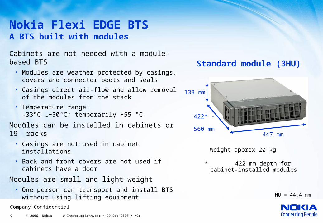
Nokia Flexi EDGE BTS A BTS built with modules
Cabinets are not needed with a module-based BTS
• Modules are weather protected by casings, covers and connector boots and seals
• Casings direct air-flow and allow removal of the modules from the stack
• Temperature range: -33°C …+50°C; temporarily +55 °C
Modules can be installed in cabinets or 19” racks
• Casings are not used in cabinet installations
• Back and front covers are not used if cabinets have a door
Modules are small and light-weight• One person can transport and install BTS
without using lifting equipment
Standard module (3HU)
133 mm
447 mm
422* - 560 mm
* 422 mm depth for cabinet-installed modules
Weight approx 20 kg
HU = 44.4 mm

10 © 2006 Nokia 0-Introductionn.ppt / 29 Oct 2006 / ACr
Company Confidential
Nokia Flexi BTS Mechanics
Front
Cable cover
Core, can be pulledout for replacement(WCDMA TRX shown)
Casing, enables removingcore without dismantlingstack
Fan, at rear. Replaceable at site
Cable entry points
Rear cover

11 © 2006 Nokia 0-Introductionn.ppt / 29 Oct 2006 / ACr
Company Confidential
Nokia Flexi BTS in traditional sites
Outdoor rooftops
Pole, Mast or Tower
Indoors

12 © 2006 Nokia 0-Introductionn.ppt / 29 Oct 2006 / ACr
Company Confidential
Nokia Flexi BTS in novel sites New opportunity to turn previous microcellular sites to macrocellular
Inside legacy BTS or new 19” cabinets
On a roof of a kiosk, bus-stop etc
Macro site installations on wall
Inside constructions like billboards etc
13 © 2006 Nokia 0-Introductionn.ppt / 29 Oct 2006 / ACr
Company Confidential
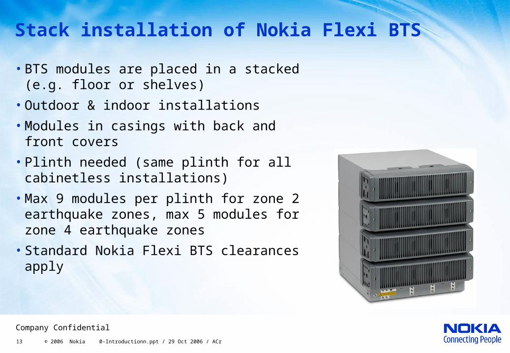
Stack installation of Nokia Flexi BTS
• BTS modules are placed in a stacked (e.g. floor or shelves)
• Outdoor & indoor installations
• Modules in casings with back and front covers
• Plinth needed (same plinth for all cabinetless installations)
• Max 9 modules per plinth for zone 2 earthquake zones, max 5 modules for zone 4 earthquake zones
• Standard Nokia Flexi BTS clearances apply

14 © 2006 Nokia 0-Introductionn.ppt / 29 Oct 2006 / ACr
Company Confidential
Wall installation of Nokia Flexi BTS
• BTS modules installed on a wall
• Outdoor & indoor installations
• Modules in casings with back and front covers
• Plinth needed
• Up to 2 modules per plinth
• Modules installed covers sideways
• 150 mm space recommended between plinths to enable cabling (see picture)
• Standard Nokia Flexi BTS clearances apply
150 mm
Cable routing
Module removal

15 © 2006 Nokia 0-Introductionn.ppt / 29 Oct 2006 / ACr
Company Confidential
Pole installation of Nokia Flexi BTS
• BTS modules installed on a pole
• Outdoor & indoor installations
• Modules in casings with back and front covers
• Plinth and pole mounting bracket needed
• Up to 2 modules per plinth and 4 per pair of brackets
• Modules installed covers sideways
• Standard Nokia Flexi clearances apply
16 © 2006 Nokia 0-Introductionn.ppt / 29 Oct 2006 / ACr
Company Confidential
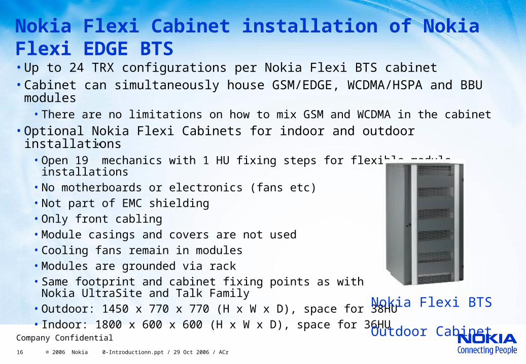
Nokia Flexi Cabinet installation of Nokia Flexi EDGE BTS•Up to 24 TRX configurations per Nokia Flexi BTS cabinet•Cabinet can simultaneously house GSM/EDGE, WCDMA/HSPA and BBU
modules• There are no limitations on how to mix GSM and WCDMA in the cabinet
•Optional Nokia Flexi Cabinets for indoor and outdoor installations• Open 19” mechanics with 1 HU fixing steps for flexible module installations• No motherboards or electronics (fans etc)• Not part of EMC shielding• Only front cabling• Module casings and covers are not used• Cooling fans remain in modules• Modules are grounded via rack• Same footprint and cabinet fixing points as with
Nokia UltraSite and Talk Family• Outdoor: 1450 x 770 x 770 (H x W x D), space for 38HU • Indoor: 1800 x 600 x 600 (H x W x D), space for 36HU
Nokia Flexi BTS Outdoor Cabinet
17 © 2006 Nokia 0-Introductionn.ppt / 29 Oct 2006 / ACr
Company Confidential
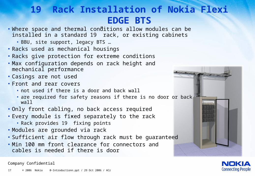
19” Rack Installation of Nokia Flexi EDGE BTS
• Where space and thermal conditions allow modules can be installed in a standard 19” rack, or existing cabinets
• BBU, site support, legacy BTS …• Racks used as mechanical housings • Racks give protection for extreme conditions• Max configuration depends on rack height and
mechanical performance• Casings are not used• Front and rear covers
• not used if there is a door and back wall• are required for safety reasons if there is no door or back wall
• Only front cabling, no back access required • Every module is fixed separately to the rack
• Rack provides 19” fixing points• Modules are grounded via rack• Sufficient air flow through rack must be guaranteed• Min 100 mm front clearance for connectors and
cables is needed if there is door