0 - COURSE COMPILED (2018 0730 1106)
129
©Copyright Trinity Consultants 2018. 1 Oil and Gas Emissions and Regulations Georgette Reeves, Director Oil and Gas Sector Services 1 These materials by Trinity Consultants are licensed under a Creative Commons Attribution- NonCommercial-No Derivatives License (CC BY-NC-ND 4.0) Logistics ˃ Phones ˃ Restrooms ˃ Breaks ˃ Lunch 2
Transcript of 0 - COURSE COMPILED (2018 0730 1106)
©Copyright Trinity Consultants 2018. 1
Oil and Gas Emissions and Regulations
Georgette Reeves, DirectorOil and Gas Sector Services
1
These materials by Trinity Consultants are licensed under a Creative Commons Attribution-NonCommercial-No Derivatives License (CC BY-NC-ND 4.0)
Logistics
˃ Phones˃ Restrooms˃ Breaks˃ Lunch
2
©Copyright Trinity Consultants 2018. 2
Introduction
˃ Georgette Reeves – Director, Oil & Gas Sector Services With Trinity for 12 years Works extensively with the regulated
community Spent first 8 years in New Mexico, now
based in Austin, Texas Has been closely following air regulations
for upstream since 2011 Sees regulations and compliance through the
lens of operators3
Course Objectives
˃ Build an awareness of potential oil and gas air quality impacts
˃ Build an awareness of the myriad of rules that apply to common oilfield equipment
˃ Build an awareness of NSPS Subpart OOOO and OOOOa including real-world applicability scenarios
˃ Engage in lively discussion and debate
4
©Copyright Trinity Consultants 2018. 3
What not to expect from the course…˃ Absolute answers to everything!
5
Two-Day Schedule˃ Tuesday, August 21
9:30 AM Start Two 10-minute breaks Lunch Two 10-minute breaks 4:30 PM End of Slides Q&A, Discussion
˃ Wednesday, August 22 8:00 AM Start Two 10-minute breaks Lunch Two 10-minute breaks 3:00 PM End of Slides Q&A, Discussion
6

©Copyright Trinity Consultants 2018. 4
Disclaimer
˃ This course and instructor are not providing legal advice;
˃ Whenever possible, always involve legal counsel to support regulatory interpretations; and
˃ The views expressed here do not represent the views of Trinity Consultants’ clients (and should any views expressed here directly conflict my client, my client is correct).
7
Who is Trinity?
8

©Copyright Trinity Consultants 2018. 5
Trinity Consultants˃ Founded 1974˃ 47 offices nationwide and China, Middle East, and U.K.˃ ~2,000 projects per year˃ Environmental and business solutions for industry˃ Expertise in air permitting, modeling, and regulatory
compliance
9
Local Flavor – Marcellus and Utica Shales
10

©Copyright Trinity Consultants 2018. 6
Utica and Marcellus Shales
11
http://oilandgas.ohiodnr.gov/portals/oilgas/pdf/EPA-fact-sheets/DrillingforNaturalGasintheMarcellusandUticaShales_EnvironmentalRegulatoryBasics.pdf
See Handout
Drilling Basics
12

©Copyright Trinity Consultants 2018. 7
Drilling Rigs-Let’s talk-Handout
https://www.osha.gov/SLTC/etools/oilandgas/13
Vertical vs. Horizontal Wells
˃ Horizontal wells are higher cost per well
˃ Horizontal wells take more time per well
˃ Multiple horizontal wells can be drilled from the same pad reducing the overall cost of multiple wells combined
https://www.dmr.nd.gov/ndgs/newsletter/NL0308/pdfs/Horizontal.pdf
14
©Copyright Trinity Consultants 2018. 8
Horizontal Drilling in the Marcellus – 5 Minute Video
https://www.youtube.com/watch?v=vvRCYLnVWG815
Completion Basics
16

©Copyright Trinity Consultants 2018. 9
Frac Location Example
15
17
Hydraulic Fracturing – see Handout
˃ Very high pressure water, proppant, chemicals mixture
˃ Used to fracture the rock and hold the fractures open
˃ Allows wells that would otherwise not be economical to produce in commercial amounts
˃ Companies are experimenting with propane, butane, and NGL fracs
18

©Copyright Trinity Consultants 2018. 10
Chesapeake Educational Video –Hydraulic Fracturing
http://www.youtube.com/watch?v=qjP-K1VaI1k (3.5 min)19
Flowback
˃ Frac water must be flowed back to the surface to clean up the well
˃ Hydrocarbon gas can be entrained in the latter part of a flowback operation
˃ Hydrocarbon gas management options: Venting Flaring/Combusting Capturing and sending to the gathering line
(“reduced emission completions”)20

©Copyright Trinity Consultants 2018. 11
Reduced Emission Completions
http://www.epa.gov/gasstar/documents/reduced_emissions_completions.pdf
21
Reduced Emission Completions – see Handout
https://www.epa.gov/sites/production/files/2016-06/documents/reduced_emissions_completions.pdf22

©Copyright Trinity Consultants 2018. 12
Flowback Gas Destruction and Capture Concerns˃ Burn bans˃ Commerciality of the well˃ Gathering company contracts
23
What are the environmental impacts of exploration and production drilling?
24
©Copyright Trinity Consultants 2018. 13
Environmental Impacts˃ Continued reliance and combustion of
fossil fuel ˃ Wastewater from drilling operations
Must be transported via trucks (truck traffic) or injected underground (groundwater concerns)
˃ Truck traffic and associated emissions Dust (PM) from travelling on unpaved roads Wear/tear on highways Public safety and high truck volume
25
˃ PM emissions from sand loading, handling, hauling, etc.
˃ VOC emissions from fugitives or venting of associated gas
˃ Combustion emissions from engines, heaters, and other combustion devices
We will focus on air emissions impacts moving forward…
26
Environmental Impacts
©Copyright Trinity Consultants 2018. 14
Hydraulic Fracturing and Flowback Emissions
27
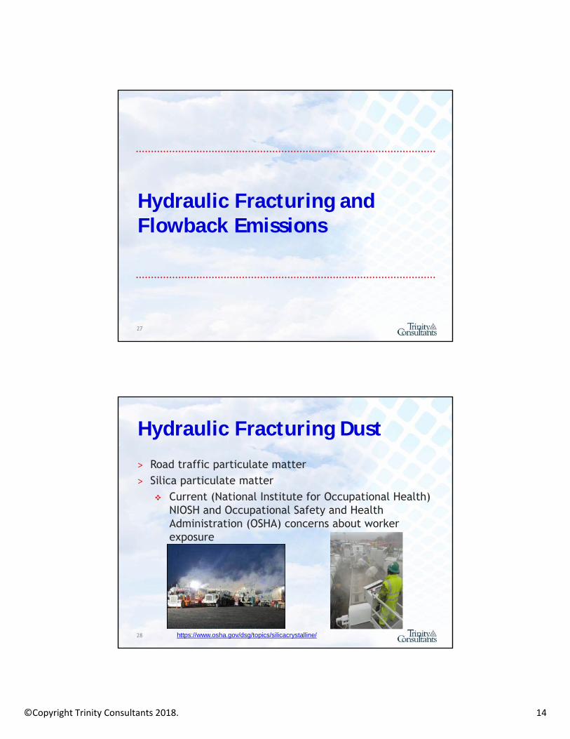
Hydraulic Fracturing Dust
˃ Road traffic particulate matter˃ Silica particulate matter
Current (National Institute for Occupational Health) NIOSH and Occupational Safety and Health Administration (OSHA) concerns about worker exposure
28 https://www.osha.gov/dsg/topics/silicacrystalline/

©Copyright Trinity Consultants 2018. 15
NIOSH Identified 7 Primary Silica Dust Sources:˃ Dust ejected from thief hatches (access ports)
on top of the sand movers during refilling operations while the machines are running (hot loading).
˃ Dust ejected and pulsed through open side fill ports on the sand movers during refilling operations
˃ Dust generated by on-site vehicle traffic. ˃ Dust released from the transfer belt under the
sand movers. 29
http://www.osha.gov/dts/hazardalerts/hydraulic_frac_hazard_alert.html
NIOSH Identified 7 Primary Silica Dust Sources:˃ Dust created as sand drops into, or is
agitated in, the blender hopper and on transfer belts.
˃ Dust released from operations of transfer belts between the sand mover and the blender; and
˃ Dust released from the top of the end of the sand transfer belt (dragon’s tail) on sand movers.
30 http://www.osha.gov/dts/hazardalerts/hydraulic_frac_hazard_alert.html

©Copyright Trinity Consultants 2018. 16
Particulate Dust Emission Factors˃ Changes to OSHA silica rule in 2016˃ Enforcement began in June 2018
31
Hydraulic Fracturing Pump Truck Engines˃ Pump trucks are equipped with ~1,500 to
~2,500 hp diesel-fired engines
32
http://www.halliburton.com/public/pe/contents/Data_Sheets/web/H/H09160.pdf

©Copyright Trinity Consultants 2018. 17
˃ Engines are subject to different rules depending on whether they are: Mobile Non-road Non-stationary Stationary
˃ Well known emission factors for engines (AP-42, vendor provided data, etc.)
˃ We will cover this in more detail later…33
Hydraulic Fracturing Pump Truck Engines
Flowback Emissions
˃ Gas as a part of a general liquid flowback˃ Predominantly gas venting from 500-BBL
(21,000 gallon frac tanks)˃ Venting or flaring while waiting on
gathering lines˃ Reduced emission completions if a
gathering line is present˃ Limited available data for emission
factors, and highly specific34

©Copyright Trinity Consultants 2018. 18
Flowback Emissions
˃ Wealth of information can be found in EPA Natural Gas STAR program, but… http://epa.gov/gasstar/documents/reduced
_emissions_completions.pdf
˃ More detailed (and up to date) information may be found in: NSPS OOOO and OOOOa reports; and GHG reports
˃ Covered in more detail later…35
Typical Production Operations
36

©Copyright Trinity Consultants 2018. 19
Typical Oil and Gas Production
Flow from wellor wells
Gas to gathering line
Oil/condensateto LACTor truck
Water toSWDor truck
Separator- heat?- vertical/horizontal?
Oil/condensate stock tank(s)
Produced watertank(s)
37
Typical Oil and Gas Production
Flow from wellor wells
Gas to gathering line
Oil/condensateto LACTor truck
Water toSWDor truck
Possible dehy
Oil/condensate stock tank(s)
Produced watertank(s)
Separator
38

©Copyright Trinity Consultants 2018. 20
Typical Oil and Gas Production
Flow from wellor wells
Gas to gathering line
Oil/Condensateto LACTor truck
Water toSWDor truck
Separator
Oil/condensate stock tank(s)
Produced watertank(s)
Separator
Compressor
39
Typical Dry Gas Production
Flow from wellor wells
Gas to gathering line
Water toSWDor truck
Separator
Produced watertank(s)
40
©Copyright Trinity Consultants 2018. 21
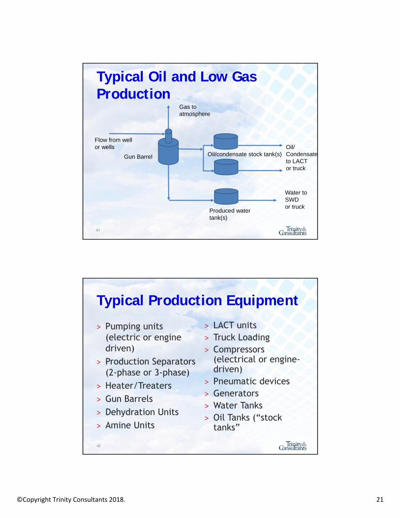
Typical Oil and Low Gas Production
Flow from wellor wells
Gas to atmosphere
Oil/Condensateto LACTor truck
Water toSWDor truck
Gun Barrel Oil/condensate stock tank(s)
Produced watertank(s)
41
Typical Production Equipment
˃ Pumping units (electric or engine driven)
˃ Production Separators (2-phase or 3-phase)
˃ Heater/Treaters˃ Gun Barrels˃ Dehydration Units˃ Amine Units
˃ LACT units˃ Truck Loading˃ Compressors
(electrical or engine-driven)
˃ Pneumatic devices˃ Generators˃ Water Tanks˃ Oil Tanks (“stock
tanks”
42
©Copyright Trinity Consultants 2018. 22
Typical Emission Control Devices˃ Flares – open or enclosed˃ Vapor Recovery Devices
Low flow compressors… Electrical or engine-driven
43
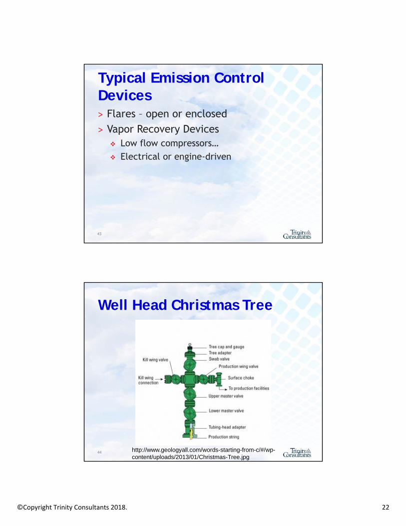
Well Head Christmas Tree
http://www.geologyall.com/words-starting-from-c/#/wp-content/uploads/2013/01/Christmas-Tree.jpg
44

©Copyright Trinity Consultants 2018. 23
Pumping Unit/Beam Pump/Sucker Rod Pump˃ May be electrically
driven˃ May also be engine
driven˃ Often operate
intermittently- can start without any warning (stay safe!)
45
Typical Oil and Gas Production
Well and pumping unit
Single well facility:• Heater/treater• Oil tanks• Water tank
46

©Copyright Trinity Consultants 2018. 24
Separation
˃ Can be atmospheric temperature
˃ Can be heated via natural gas fire tube (heater/treater)
˃ Can be horizontal or vertical
˃ Typically referred to be dimensions
˃ Protected from overpressure by relief valves
47
Multi-Well Tank Battery
˃ Larger and more tanks for multiple wells
˃ Most are fixed roof steel or fiberglass tanks that are between 210 bbl – 500 bbl
˃ Most often there will be 1 load out connection per tank to truck oil away
48

©Copyright Trinity Consultants 2018. 25
LACT Unit
˃ Lease Accounting Custody Transfer Unit
˃ Used to meter oil into a pipeline if it is not trucked
http://www.cjemc.com/lact/
49
Dehydration Flow Diagram
GRI GLYCalc (Glycol Dehydration Handbook) 50
©Copyright Trinity Consultants 2018. 26
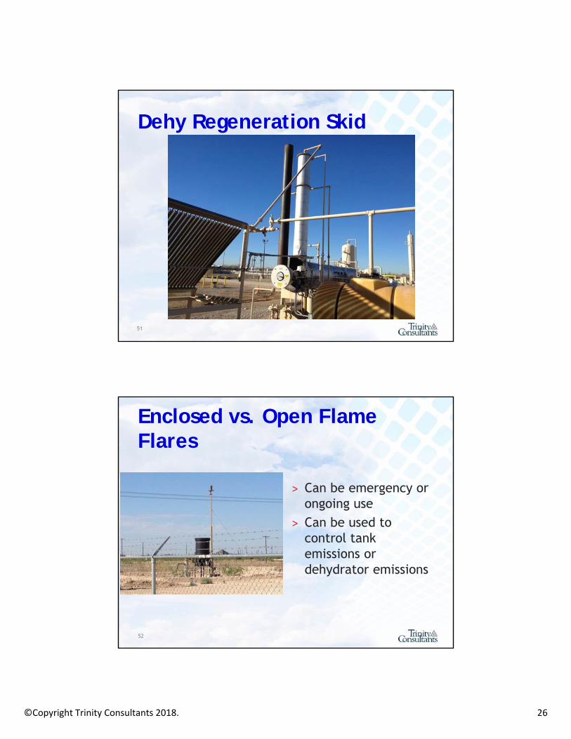
Dehy Regeneration Skid
51
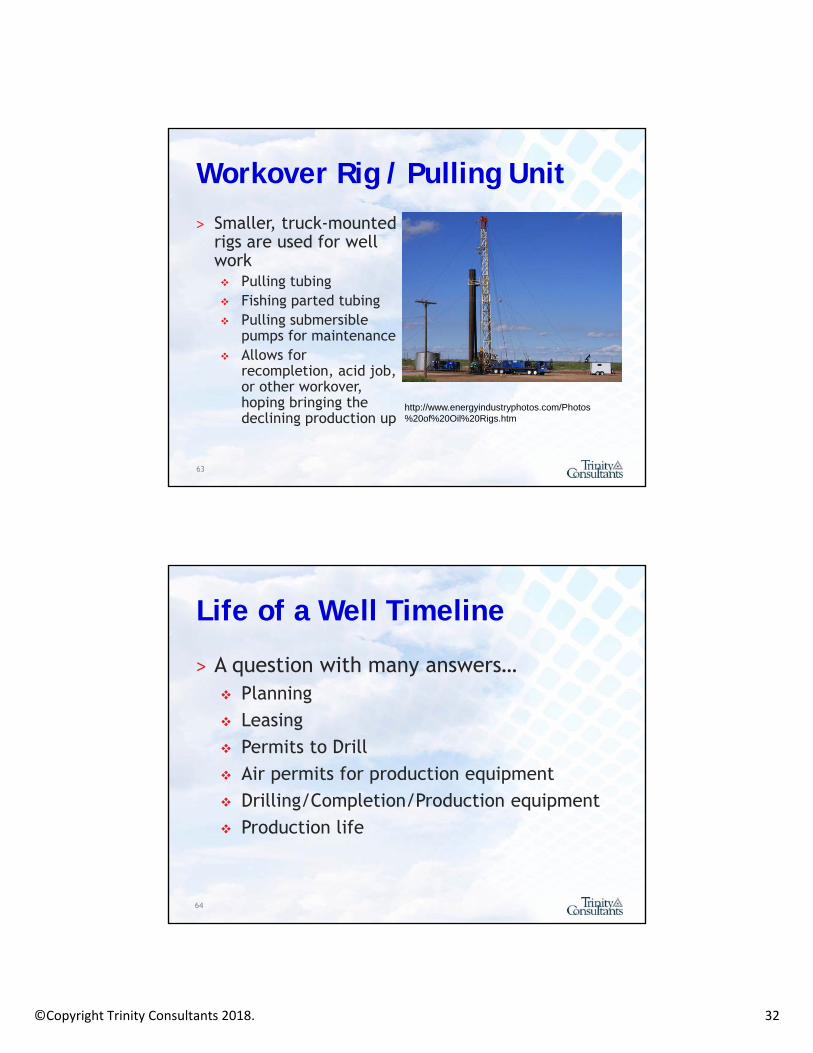
Enclosed vs. Open Flame Flares
˃ Can be emergency or ongoing use
˃ Can be used to control tank emissions or dehydrator emissions
52

©Copyright Trinity Consultants 2018. 27
Compressors and Engines
˃ Well site compressors˃ Gathering system
compressors (compressor stations)
˃ Gas plant feed and residue compressors
˃ Transmission compressors
˃ Natural gas-fired; electrical
˃ Emergency generatorshttp://www.freeportlng.com/regas_technology.asp
53
Compressor Engine
54

©Copyright Trinity Consultants 2018. 28
Pneumatic Controllers – See Handout
http://www.epa.gov/gasstar/documents/ll_pneumatics.pdf55
Pneumatic Controller
56

©Copyright Trinity Consultants 2018. 29
Pneumatic Controller
57
Pneumatic Controller
58

©Copyright Trinity Consultants 2018. 30
Pneumatic Controller
59
Pneumatic Controllers
˃ Any pneumatic device that bleeds in excess of 6 scfh (over 50 Mcf per year) is considered a high-bleed device by the Natural Gas STAR Program.
˃ Types: Continuous bleed devices are used to
modulate flow, liquid level, or pressure and will generally vent gas at a steady rate
http://www.epa.gov/gasstar/documents/ll_pneumatics.pdf60

©Copyright Trinity Consultants 2018. 31
Pneumatic Controllers
Actuating or intermittent bleed devices perform snap-acting control and release gas only when they stroke a valve open or closed or as they throttle gas flows (“Snap Acting”)
Self-contained devices release gas into the downstream pipeline, not to the atmosphere
61
Pneumatic Pumps
˃ Pictured: Diaphragm Pump
˃ Often used to empty water from containment areas
62
©Copyright Trinity Consultants 2018. 32
Workover Rig / Pulling Unit
˃ Smaller, truck-mounted rigs are used for well work Pulling tubing Fishing parted tubing Pulling submersible
pumps for maintenance Allows for
recompletion, acid job, or other workover, hoping bringing the declining production up
http://www.energyindustryphotos.com/Photos%20of%20Oil%20Rigs.htm
63
Life of a Well Timeline
˃ A question with many answers… Planning Leasing Permits to Drill Air permits for production equipment Drilling/Completion/Production equipment Production life
64

©Copyright Trinity Consultants 2018. 33
Discussion
˃ What 1-3 activities/operations concern you the most? Why?
˃ What sources would be subject to your air permitting requirements?
65
END OF SECTION 1
©Copyright Trinity Consultants 2018. 34
Section 2: High Level Overview of Applicable Air Quality Regulations and Reporting Requirements
Air Quality is a Dynamic, Changing Field
Always be certain to obtain the latest forms, policies, and regulations from the appropriate
regulatory authority before determining permitting and compliance needs for your site. The information provided in this manual, while up-to-date when printed, is subject to change
as regulatory authorities update forms, policies and regulations. You are encouraged to use this manual as an educational reference, but it is not a substitute for independent research and
verification, and the application of sound professional judgment and analysis in real-time
permitting and compliance situations.UTILIZE THE EXPERTS AVAILABLE TO YOU!
68

©Copyright Trinity Consultants 2018. 35
A Note on Executive Orders…
69
Executive Orders
˃ Executive Orders direct agencies to take action – they do not, in and of themselves, rescind, revise, replace, suspend or modify any existing regulations.
˃ Any changes to existing regulations must undergo the full rulemaking process OR must already be stayed through judicial review.
70

©Copyright Trinity Consultants 2018. 36
Regulatory Rulemaking˃ Regulatory rulemaking takes time.
Boiler MACT has been in various stages for more than TEN years!
NSPS OOOO took a full year from proposed to final, which was breakneck speed for EPA.
Even OOOOa took 10 months- and that was an update to an existing regulation.
˃ Regulatory rulemaking requires stakeholder input. There are more than ~50,000 comments on the
docket regarding regulatory reform. Comment period opened April 13 and closed May 15.
71
Moving on!
72

©Copyright Trinity Consultants 2018. 37
Permitting and Compliance
Permitting Compliance
“That’s a NSPS JJJJ engine.”
“NSPS JJJJ requires an initial performance test and emission reduction package on the unit and records to demonstrate compliance.”
73
Permitting Operations Compliance
“That’s a NSPS JJJJ engine.”
“NSPS JJJJ requires an initial performance test and emission reduction package on the unit and records to demonstrate compliance.”
“NSPS JJJJ testing is complete and engine meets the required
standards.”
Permitting and Compliance
74

©Copyright Trinity Consultants 2018. 38
Something to keep in mind…
75
Federal Air Quality Rules˃ New Source Performance Standards
(NSPS) Applies only to new, modified and
reconstructed sources Regulates “criteria pollutants”
˃ National Emission Standards for Hazardous Air Pollutants (NESHAP) Applies to both new and existing sources Regulates Hazardous Air Pollutants (HAPs)
˃ Mandatory GHG Reporting Rule76

©Copyright Trinity Consultants 2018. 39
New Source Performance Standards (NSPS)
New Source Performance Standards
Criteria Pollutants (e.g., VOC, NOx, CO, PM, SO2)
OOOOa adds GHG (as does Subpart TTTT)
Affected facilities at all types of sites
Only regulates New, Modified, or Reconstructed Sources
Proposal date is effective date.Note: the definition of “new,” “modified” and “reconstructed are critical when determining NSPS applicability!
Construction/Affected Facility Definitions˃ Construction - fabrication, erection, or
installation of an affected “facility” ˃ Affected facility - with reference to a
stationary source, any apparatus to which a standard is applicable e.g., an engine vs. a compressor e.g., a storage tank vs. gas well completion
˃ Relocating an affected facility is notconstruction, modification, or reconstruction under NSPS and does not trigger the rule Permitting may be required at the new site
78
©Copyright Trinity Consultants 2018. 40
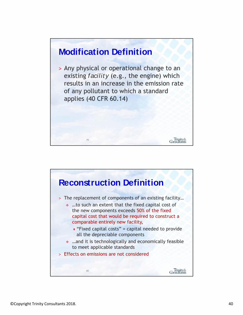
Modification Definition
˃ Any physical or operational change to an existing facility (e.g., the engine) which results in an increase in the emission rate of any pollutant to which a standard applies (40 CFR 60.14)
79
Reconstruction Definition
˃ The replacement of components of an existing facility… …to such an extent that the fixed capital cost of
the new components exceeds 50% of the fixed capital cost that would be required to construct a comparable entirely new facility,♦ “Fixed capital costs” = capital needed to provide
all the depreciable components …and it is technologically and economically feasible
to meet applicable standards˃ Effects on emissions are not considered
80

©Copyright Trinity Consultants 2018. 41
General NSPS Requirements
˃ Applies only to “new, modified or reconstructed sources”. Not existing. These definitions and concepts are tricky
˃ Requirements typically consist of: Emission limitations Performance testing (e.g., stack testing) Parametric and/or emissions monitoring Recordkeeping Notifications Reporting
˃ The rules typically apply to the owner/operator˃ Engine manufacturers have requirements
NSPS Subpart A – Notification and Reporting Timeline - Handout

©Copyright Trinity Consultants 2018. 42
How are HAPs Regulated?˃ Handout – HAPs Poster˃ Risk-based regulations (NESHAP)
40 CFR 61 – 1970 Clean Air Act Amendments 40 CFR 63 – 1990 Clean Air Act Amendments
♦ Congress identified the HAPs, EPA identified the industries that emit most of those HAPs
♦ Standards for HAP major sources are based on MACT; standards for HAP area sources are based on GACT
♦ Applies to new and existing sources♦ This is in contrast to criteria pollutants, which are regulated
based on monitored, ambient standards
˃ Therefore, there are no attainment designations83
National Emission Standards for Hazardous Air Pollutants
National Emission Standards for Hazardous Air Pollutants (NESHAP) – NOT NSPS
Hazardous Air Pollutants (e.g., Formaldehyde, Benzene, Toluene, etc.)
Affected facilities at “major” or “area” [e.g., minor] sources
Regulates both new and existing sources
Proposal date is effective date.
Note: More stringent requirements for new sources than existing sources, and more stringent requirements for major sources than area sources.
©Copyright Trinity Consultants 2018. 43
State Toxics
˃ Some states have a list of toxics that must be evaluated
˃ Example: Texas has more than 5,000 listed compounds. Colorado also has a long list of compounds maintained in Regulation 3, Appendix B.
˃ Some states, like Wyoming, target compounds on a case-by-case basis
˃ Check with your regulator
85
Greenhouse Gas Reporting
˃ 40 CFR Part 98 – Mandatory GHG Reporting Rule
˃ Due annually on March 31st
˃ Common subparts for O&G: Subpart C – Stationary Combustion Subpart PP – Suppliers of CO2 Subpart UU – Injection of CO2 Subpart NN – Suppliers of NGL Subpart W – Oil and Natural Gas Systems
86

©Copyright Trinity Consultants 2018. 44
GHG Reporting
˃ Reported information is widely publically available
˃ Reported information is extremely detailed
˃ Bloggers, NGOs and others can analyze information to draw conclusions about your operations
˃ Stakeholders (i.e., shareholders) can use the information to evaluate trends
SourceTypeOffshoreProduction
OnshoreProduction
NaturalGasProcessing
NaturalGasTransmissionCompression
GatheringandBoosting(NEW)
TransmissionPipelineBlowdowns(NEW)
§98.232(b) §98.232(c) §98.232(d) §98.232(e) §98.232(j) §98.232(m)
NaturalGasPneumaticDeviceVenting X X X
NaturalGas‐DrivenPneumaticPumpVenting X X
AcidGasRemovalVents X X XDehydratorVents X X X
WellVentingforLiquidsUnloading X
WellVentingDuringWellCompletionsandWorkoversfromHydraulicFracturing X
WellVentingDuringWellCompletionsandWorkoverswithoutHydraulicFracturing X
BlowdownVentStacks X X X X
OnshoreProductionStorageTanks X X
TransmissionStorageTanks X
WellTestingVentingandFlaring X
FlareStacks X X
CentrifugalCompressorVenting X X X X
ReciprocatingCompressorRodPackingVenting X X X X
OtherEmissionsfromEquipmentLeaks X X X
PopulationCountandEmissionFactors X X
Vented,EquipmentLeaks,andFlareEmissionsIdentifiedinBOEMREGOADSStudy X
EnhancedOilRecoveryHydrocarbonLiquidsDissolvedCO2
X
EnhancedOilRecoveryInjectionPumpBlowdown X
OnshorePetroleumandNaturalGasProduction,NaturalGasDistribution,Gathering/Boosting
CombustionEmissionsX X

©Copyright Trinity Consultants 2018. 45
SourceTypeUndergroundStorage LNGStorage LNGImportandExportEquipment Distribution
§98.232(f) §98.232(g) §98.232(h) §98.232(i)
NaturalGasPneumaticDeviceVenting X
NaturalGas‐DrivenPneumaticPumpVenting
AcidGasRemovalVents
DehydratorVents
WellVentingforLiquidsUnloading
WellVentingDuringWellCompletionsandWorkoversfromHydraulicFracturing
WellVentingDuringWellCompletionsandWorkoverswithoutHydraulicFracturing
BlowdownVentStacks XOnshoreProductionStorageTanks
TransmissionStorageTanks
WellTestingVentingandFlaring
FlareStacksCentrifugalCompressorVenting X X X
ReciprocatingCompressorRodPackingVenting X X X
OtherEmissionsfromEquipmentLeaks X X X X
PopulationCountandEmissionFactors X X X X
Vented,EquipmentLeaks,andFlareEmissionsIdentifiedinBOEMREGOADSStudy
EnhancedOilRecoveryHydrocarbonLiquidsDissolvedCO2
EnhancedOilRecoveryInjectionPumpBlowdown
OnshorePetroleumandNaturalGasProduction,NaturalGasDistribution,Gathering/Boosting
CombustionEmissionsX
Air rules that impact O&G operations…˃ Engine rules (NSPS JJJJ, IIII and MACT ZZZZ)˃ Turbine rules (NSPS GG, KKKK)˃ Compressors (NSPS OOOO/a)˃ Dehydrators (NESHAP HH, HHH)˃ Greenhouse gas rules (Subpart W)˃ Tank rules (NSPS Ka, Kb, OOOO/a)˃ Compressor rule (NSPS OOOO/a)˃ Pneumatic devices & pumps (NSPS OOOO/a)˃ Leaks (NSPS VV, VVa, OOOO/a and state rules)˃ Wellheads (NSPS OOOO/a)˃ Blowdowns (state rules)˃ Flares (various)
90

©Copyright Trinity Consultants 2018. 46
Air Quality Permitting Basics
91
Types of Air Quality Permits
˃ Construction or New Source Review (NSR) Authorizes construction and modification of sources
♦ Major Source Permits (i.e., Prevention of Significant Deterioration (PSD), Nonattainment New Source Review (NNSR))
♦ Minor Source Permits♦ Exemptions, waivers, permits by rule, others
˃ Operating Permits Authorizes the operation of large (major) sources Designed to keep larger sources more accountable Typically obtained after construction or operation
has commenced
92

©Copyright Trinity Consultants 2018. 47
Construction Permits: When do I need authorization to build? ˃ When new construction or a change is planned that will
result in (or potentially result in) emissions of an air contaminant
˃ You should ALWAYS evaluate your projects for potential emissions of air contaminants
˃ Must have permit in-hand before construction begins or must have evaluated exemptions and flexibility provisions
˃ If you have an existing permit: Does the change impact past representations to the
agency (even if there is no emissions increase or emissions will stay under permit limits)?
93
How Long will it Take?
˃ Typically: Many states have expedited authorization
mechanisms for O&G Production sites Downstream of this (large midstream,
transmission, processing), case-by-case permitting is typically required and can take 6 to 12 months
˃ Sometimes faster permitting can be obtained, but the trade off could be significant.
94
©Copyright Trinity Consultants 2018. 48
˃ Lower emissions = lower level permitting. ˃ How can emissions be lowered?
“Voluntary” monitoring of components; Restrictions on operating hours; Installation of controls not otherwise
required; Increase of recordkeeping; Decrease of flexibility.
95
How Long will it Take?
Key Steps in NSR Permitting (State-dependent)
1. Identify all equipment with actual or potentialemissions at the site
2. Quantify the site’s Potential to Emit (PTE) Is the site a “major” or “minor” source? Attainment or nonattainment?
3. Determine permitting applicability4. Determine control requirements5. Complete forms and permit package6. Demonstrate compliance with air quality standards7. Submit the application and negotiate permit terms8. Comply with the permit
96

©Copyright Trinity Consultants 2018. 49
Permitting – Big Picture
˃ If using a device to reduce emissions, here’s one practical approach: 1. How does it reduce emissions? 2. How can I demonstrate that it reduces
emissions? 3. How can I demonstrate that the device is
working properly?
˃ Nearly all permit requirements boil down to demonstrating these three items.
97
Permitting Thresholds – Big Picture˃ 250 tons per year or more: Prevention
of Significant Deterioration (PSD) Permitting
˃ 100 tons per year or more: Major source permitting Federal operating permit Construction permit
˃ Less than 100 tons per year: Minor source permitting “Source Registrations”
98

©Copyright Trinity Consultants 2018. 50
Reported as “CO2e”
Pb
CriteriaPollutants
HazardousAir Pollutants (HAPs)
Ozone-DepletingSubstances
GHGs
PM10PM2.5SO2NOxVOCCO
187 Pollutants: BTEX
Formaldehyde
CO2N2OCH4
CFCs
Regulated Pollutants
99
Regulated Pollutants
˃ Criteria Pollutants NOx, CO, SO2, ozone, lead, particulate
matter Regulated through:
♦National Ambient Air Quality Standards (NAAQS)
♦New Source Performance Standards (NSPS)♦ State Standards♦Air Permitting
100

©Copyright Trinity Consultants 2018. 51
Regulated Pollutants
˃ Hazardous Air Pollutants e.g., benzene, toluene, xylene 187 federally listed HAPs Regulated through:
♦A command and control regulatory structure (NESHAP)
♦Air permitting
101
Regulated Pollutants
˃ CFC and HCFC Regulated through leak detection and repair,
and through a technician certification program
˃ Climate Change CO2, N2O, SF6, CH4, others Air permitting
102

©Copyright Trinity Consultants 2018. 52
END OF PART 2
103
Section 3: Air Quality Rules by Equipment Type & Event
104
©Copyright Trinity Consultants 2018. 53
Equipment Regulated by the Clean Air Act˃ Engines˃ Compressors˃ Dehydrators˃ Continuous Bleed Pneumatic Controllers˃ Storage Tanks˃ Combustors (flares, heaters, VOC and/or H2S
destruction devices)˃ Acid Gas Removal˃ Fugitives (i.e., component counts: flanges, connectors,
valves, etc.) at gas processing plants˃ Fugitives at well sites and compressor stations
105
Activities Regulated by the Clean Air Act
˃ Blowdowns/Venting (indirectly)˃ Flaring˃ Hydraulic Fracturing at Natural Gas and
Oil Wells˃ Well Venting for Liquids Unloading˃ Well Testing Venting and Flaring˃ Natural Gas Well Workovers and
Completions106

©Copyright Trinity Consultants 2018. 54
Other Potentially Regulated Sources˃ Haul Roads (source of PM)˃ Truck Loading˃ Rail Loading˃ Barge Loading˃ Any source of Methane (Colorado)˃ Pigging (Pennsylvania)˃ Differs from state to state!
107
Definitions in Air Quality
˃ EPA provides definitions; they don’t always make a lot of sense for real world operations. What is “natural gas processing”? What is “natural gas”? What is a “facility”? What is “new”? What is “modified” or “reconstructed”? What is “stationary” versus “mobile” versus
“portable” [important!]
[important!]
108

©Copyright Trinity Consultants 2018. 55
Air Quality Rules - Engines
Air Quality Rules – EnginesHANDOUT˃ Permitting˃ 40 CFR Part 60, NSPS JJJJ: “New” natural gas
fired stationary engines˃ 40 CFR Part 60, NSPS IIII: “New” diesel fired
stationary engines˃ 40 CFR Part 63, MACT ZZZZ: “New” and
“existing” stationary engines More stringent requirements for “new” engines
than “existing” engines
˃ RICE Poster Handout˃ 40 CFR Part 98, Subpart W: GHG Reporting110

©Copyright Trinity Consultants 2018. 56
˃ Existing Engines: Subject to ZZZZ requirements?
˃ Existing Engines: Has it been “reconstructed” and now subject to requirements for “new” stationary engines? What is a “modification” under NSPS? What is a “reconstruction” under NSPS?
˃ Engines that Move: Permitting?
Engines – Things to Watch For
111
Stationary / Nonroad Engine DefinitionsStationary internal combustion engine means…
any internal combustion engine, except combustion turbines, that converts heat energy into mechanical work and is not mobile. Stationary ICE differ from mobile ICE in that a stationary internal combustion engine is not a nonroad engine as defined at 40 CFR 1068.30 (excluding paragraph (2)(ii) of that definition), and is not used to propel a motor vehicle, aircraft, or a
vehicle used solely for competition. Stationary ICE include reciprocating ICE, rotary ICE, and other ICE, except combustion turbines.
Nonroad engine means…(2) An internal combustion engine is not a nonroad engine if it meets any of the following criteria:
(iii) The engine otherwise included in paragraph (1)(iii) of this definition remains or will remain at a location for more than 12 consecutive months or a shorter period of time for an
engine located at a seasonal source. A location is any single site at a building, structure, facility, or installation. Any engine (or engines) that replaces an engine at a location and that is
intended to perform the same or similar function as the engine replaced will be included in calculating the consecutive time period. An engine located at a seasonal source is an engine that
remains at a seasonal source during the full annual operating period of the seasonal source. A seasonal source is a stationary source that remains in a single location on a permanent basis (i.e., at least two years) and that operates at that single location approximately three months (or more)
each year. See §1068.31 for provisions that apply if the engine is removed from the location.
112

©Copyright Trinity Consultants 2018. 57
Engines – Things to Watch For˃ New to You ≠ New (but make sure you have
records to prove it)˃ Has the engine been modified or reconstructed?˃ New engines subject to NSPS
Requirements typically consist of:♦ Emission limitations♦ Performance testing (e.g., stack testing)♦ Parametric and/or emissions monitoring♦ Recordkeeping♦ Notifications♦ Reporting
˃ The rules typically apply to the owner/operator˃ Engine manufacturers have requirements113
Owner/Operator
˃ Owner or operator means any person who owns, leases, operates, controls, or supervises an affected facility or a stationary source of which an affected facility is a part [40 CFR Part 60, Subpart A]
˃ If a rental engine is owned by Company X, and leased to Company Y for use at Company Y’s site, who is the owner/operator of the engine?
114

©Copyright Trinity Consultants 2018. 58
Engines – Things to Watch For˃ Beware the claim “no permit is required” or “our
engine is already permitted” Vendors may have unit permitted, but often the authorization
is for the engine only When setting an engine on-site, all emissions must be
considered
˃ Watch for engine “swaps” (Re)placement of “like kind” with a different serial number (Re)placement of engine different than what was expected
˃ Temporary units are not excluded from regulation (but in some cases, “portable” units are)
115
Engines - Enforcement
˃ Engines are easy for inspectors to find˃ Missing requirements for an engine
subject to NSPS or MACT is a federal issue: EPA could get involved
˃ Engines are a large area of risk for this industry
˃ Fines are calculated per violation (engine) per day
116
©Copyright Trinity Consultants 2018. 59
Engines – GHG Reporting
˃ Account for fuel combusted in engines >130 horsepower only (as long as they are not driving compressors);
˃ Account for fuel combusted in all compressor-driver engines.
˃ NEW for 2016: track fuel consumption at boosting/gathering stations, basin-wide, for GHG reporting.
117
Engines – Calculating Emissions˃ Manufacturer/vendor data
Correct to site horsepower Ensure proper fuel has been modeled Compare to applicable standards to ensure
compliance VOC data may not include formaldehyde
˃ U.S. EPA AP-42 Sections 3.1 and 3.2 for engines and turbines
˃ Continuous Emissions Monitors (CEMs)˃ Stack Test Data
Be aware of site conditions when test was conducted; must be representative.
118

©Copyright Trinity Consultants 2018. 60
Air Quality Rules -Compressors
Air Quality Rules -Compressors˃ 40 CFR Part 60, NSPS OOOO and OOOOa
Reciprocating compressors located at a well site are exempt; and
Centrifugal compressors located at a well site or equipped with dry seals are exempt.
˃ 40 CFR Part 63, Subpart HH and HHH Compressors in volatile HAP service at major
sources not covered by another NSPS (>10% by weight VOHAP)
˃ 40 CFR Part 98, Subpart W Maintain a basin-wide count of all compressors,
both on well sites and [new for 2016] off.120

©Copyright Trinity Consultants 2018. 61
A Word on NSPS OOOO and OOOOaThis subpart establishes emission standards and compliance schedules for the control of [GHG], volatile organic compounds (VOC) and sulfur dioxide (SO2) emissions from affected facilities in the crude oil and natural gas source category that commence construction, modification or reconstruction after September 18, 2015.
Crude oil and natural gas source category means: 1. Crude oil production, which includes the well and extends to the
point of custody transfer to the crude oil transmission pipeline or any other forms of transportation; and
2. Natural gas production, processing, transmission, and storage, which include the well and extend to, but do not include, the local distribution company custody station.
121
Compressors – Things to Watch For˃ GHG reporting applies to all compressors˃ NSPS rules could apply to compressors
constructed, modified or reconstructed after 8/23/2011 Pay close attention to “modified” and
“reconstructed” Expect a lot of questions regarding
compressors, and their location & manufacture dates
122

©Copyright Trinity Consultants 2018. 62
˃ Centrifugal compressors equipped with wet seals (not at a well site facility) constructed, modified or reconstructed >8/23/2011 but before 9/18/2015: Reduce VOC emissions from each wet seal fluid degassing
system by ≥95.0 percent If using a control device, equip with specified cover and
connect through a closed vent system to a control device Conduct initial inspection Install and operate continuous parameter monitoring system
(CPMS) Initial performance test required
Standards for Centrifugal Compressors
˃ Centrifugal compressors equipped with wet seals (not at a well site facility) constructed, modified or reconstructed >9/18/2015: Reduce VOC emissions from each wet seal fluid degassing
system by ≥95.0 percent Equip with P.E. certified closed vent system to a control
device Conduct initial inspection Install and operate continuous parameter monitoring system
(CPMS) Initial performance test required
Standards for Centrifugal Compressors
©Copyright Trinity Consultants 2018. 63
Standards for Reciprocating Compressors˃ Applies to reciprocating compressors not
located at a well site constructed, modified, reconstructed >8/23/2011
˃ Primary requirement is to replace the rod packing or otherwise collect vapors
˃ You can choose to replace rod packing before either of the following occur: the compressor has operated for 26,000
hours; or 36 months from the last replacement.
Compressors - Enforcement
˃ None yet.
126

©Copyright Trinity Consultants 2018. 64
Compressors – Calculating Emissions˃ 40 CFR Part 98, Subpart W
Upstream: per compressor emission factor for rod packing venting
Gas processing and transmission: measured rod packing emissions
˃ Others?
127
Air Quality Rules - Blowdowns
128

©Copyright Trinity Consultants 2018. 65
Blowdowns
˃ 40 CFR Subpart 98, Subpart W Transmission pipeline blowdowns Blowdowns in the gathering/boosting
segment Blowdowns in the gas processing segment
˃ Not specifically regulated by federal rules, broadly covered under state-level “startup, shutdown and maintenance” (SSM) or “maintenance, startup and shutdown” (MSS) for permitting.
Blowdowns – Calculating Emissions˃ Need to know:
Volume of the gas between isolation valves Frequency of events Duration of events Gas constituents; extended gas analysis
˃ Develop “standard” blowdown scenarios to quantify emissions
˃ Distinguish between blowdowns that are routine vs. those due to upsets
130

©Copyright Trinity Consultants 2018. 66
Blowdowns - Enforcement
˃ When blowdown (or any MSS/SSM) activities would case a more stringent permit Facility is permitted at 98 tpy, but with
blowdowns exceeds 100 tpy)
˃ Enforcement varies from state-to-state, and is often “event dependent” Texas is fairly advanced in this area
131
Air Quality Rules - Pneumatic Controllers

©Copyright Trinity Consultants 2018. 67
Air Quality Rules – Continuous Bleed Pneumatic Controllers˃ 40 CFR Part 60, NSPS OOOO and OOOOa
Requires the use of intermittent bleed devices or continuous bleed devices with a bleed rate <6scf/hrfor anything installed after October, 2013
Requires use of air instrumentation at gas processing plants
˃ 40 CFR Part 98, Subpart W Count and classification
♦ High bleed♦ Low bleed♦ Intermittent bleed
133
Definitions – OOOO and Subpart W˃ Natural Gas-Driven Pneumatic Controller
An automated instrument powered by pressurized natural gas and used for maintaining a process condition such as liquid level, pressure, delta-pressure and temperature.
˃ Bleed Rate The rate in standard cubic feet per hour at
which natural gas is continuously vented (bleeds) from a pneumatic controller.
134

©Copyright Trinity Consultants 2018. 68
Definitions
˃ Natural Gas-Driven Pneumatic Controller OOOO: An automated
instrument powered by pressurized natural gas and used for maintaining a process condition such as liquid level, pressure, delta-pressure and temperature.
OOOOa (added): A pneumatic controller powered by pressurized natural gas
Definitions˃ Continuous Bleed
OOOO: A continuous flow of pneumatic supply natural gas to the process control device (e.g., level control, temperature control, pressure control) where the supply gas pressure is modulated by the process condition, and then flows to the valve controller where the signal is compared with the process set-point to adjust gas pressure in the valve actuator.
OOOOa: A continuous flow of pneumatic supply natural gas to a pneumatic controller.
˃ Intermittent / Snap-action Pneumatic Controller OOOO: Means a pneumatic controller that vents non-
continuously. OOOOa: Means a pneumatic controller that is designed to vent
non-continuously.

©Copyright Trinity Consultants 2018. 69
Continuous Bleed Pneumatic Controllers˃ Each continuous bleed pneumatic
controller at natural gas processing plants must have a bleed rate of zero Applies to those pneumatic controllers that
are new, modified, or reconstructed after August 23, 2011
Effective October 15, 2012
˃ Each new continuous bleed pneumatic controller must be tagged with month/year of installation.
137
˃ Each continuous bleed pneumatic controller between the wellhead and the natural gas transmission segment (excluding natural gas processing plants) must have a bleed rate of ≤6 scfh Anything modified, constructed or reconstructed on or after
October 15, 2013 between the wellhead and a natural gas processing plant
˃ Each new continuous bleed pneumatic controller must be tagged with month/year of installation.
˃ Must have records of bleed rate of each tagged device.˃ Higher bleed rate devices can be used if determined
“functionally necessary.”
Continuous Bleed Pneumatic Controllers
138

©Copyright Trinity Consultants 2018. 70
Natural Gas Driven Pneumatic Controllers – Subpart W˃ Count of all pneumatic controllers; ˃ Classification of all pneumatic controllers
into three categories: High bleed (>6 scf/hr); Low bleed (<6 scf/hr); and Intermittent bleed.
139
Continuous Bleed Pneumatic Controllers - Enforcement˃ None yet however…˃ EPA has released documentation relating to
pneumatics, their contribution to air emissions, and their significance.
˃ EPA had included extensive questions on a recent industry-wide Information Collection Request (ICR) How many do you have? How do you determine whether it is a continuous
bleed device?
140
©Copyright Trinity Consultants 2018. 71
Natural Gas Pneumatic Diaphragm Pumps
141
Definition: Natural Gas Driven Diaphragm Pump [60.5430a]
Natural gas-driven diaphragm pump means a positive displacement pump powered by pressurized natural gas that uses the reciprocating action of flexible diaphragms in conjunction with check valves to pump a fluid. A pump in which a fluid is displaced by a piston driven by a diaphragm is not considered a diaphragm pump for purposes of this subpart. A lean glycol circulation pump that relies on energy exchange with the rich glycol from the contactor is not considered a diaphragm pump.
142

©Copyright Trinity Consultants 2018. 72
Pneumatic Pumps [60.5430a]
˃ Pneumatic pumps constructed, modified or reconstructed at an existing site after September 18, 2015 must control emissions or determine (via PE certification) that control is not feasible; or
˃ New sites constructed after September 18, 2015 with pneumatic pumps must be controlled, or submit reports of deviations.
Pneumatic Pumps [60.5365a(h), 60.5393a]˃ Natural gas pneumatic diaphragm pumps located at a
gas processing facility must have a bleed rate of 0 scf/h.
˃ Natural gas pneumatic pumps at greenfield well sites must reduce emissions by 95%. If control device cannot meet 95% reduction, must still
connect to the control device & report reduction efficiency; or If no control device is on-site and unable to route to a
process, maintain records and “report.”
˃ Well site exemption for limited-use pumps (operation < 90 days per year).
144

©Copyright Trinity Consultants 2018. 73
˃ Natural gas pneumatic diaphragm pumps at non-greenfield well sites must reduce emissions by 95% If control device cannot meet 95% reduction, must
still connect to the control device & report reduction efficiency; or
If no control device is on-site and unable to route to a process, maintain records and report; or
If infeasible to route to control or process, submit P.E. certification to support claim of infeasibility
Infeasibility could be based on safety, distance, pressure losses/differentials, or the ability of the control to handle pump emissions
145
Pneumatic Pumps [60.5365a(h), 60.5393a]
Air Quality Rules – Storage Tanks

©Copyright Trinity Consultants 2018. 74
Air Quality Rules – Storage Tanks˃ 40 CFR Part 98, Subpart W˃ 40 CFR Part 60 NSPS OOOO/a˃ 40 CFR Part 60, NSPS Ka˃ 40 CFR Part 60, NSPS Kb (>7/23/1984,
>1,000 bbl, after custody transfer)˃ 40 CFR Part 63, NESHAP HH (only if
potential to flash at major sources)˃ State and/or local permitting
requirements147
Storage Tanks Subject to OOOO and OOOOa
˃ NSPS OOOO applies to individual tanks that emit >6 tpy VOC PTE that: were constructed, modified, or reconstructed after
August 23, 2011; are located in the:
♦ oil and natural gas production segment♦ natural gas processing segment♦ natural gas transmission and storage segment
Contain crude oil, condensate, produced water or intermediate hydrocarbon liquids
˃ (Generally) install controls within 60 days of commencing operation.

©Copyright Trinity Consultants 2018. 75
Standards for Storage Vessels
˃ Tanks with potential emissions >6 tpy: Reduce VOC emissions by ≥ 95.0 percent through
use of a control device or floating roof If using a control device, equip with specified cover
and connect through a closed vent system to a control device
If constructed, modified or reconstructed after 9/18/2015, P.E. certification on CVS
˃ Tanks have 30 days from startup to calculate emissions and 60 days from startup to meet control requirements
NSPS Subpart OOOO and OOOOaStorage Vessel Exit Ramp˃ Once uncontrolled emissions drop <4 tpy, the control
device can be removed from the storage vessel; Must be demonstrated through 12 consecutive month
demonstration of emissions less than 4 tpy
˃ Must re-calculate emissions monthly to ensure not >4 tpy
˃ Must take into account anything that could increase emissions (e.g., fracking of a nearby well)
©Copyright Trinity Consultants 2018. 76
P.E. Certification and CVS
˃ Ensure CVS is appropriately designed by approval from a qualified P.E. certification Keep on file, submit with annual report
˃ Qualified Professional Engineer means an individual who is licensed by a state as a Professional Engineer to practice one or more disciplines of engineering and who is qualified by education, technical knowledge and experience to make the specific technical certifications required under this subpart. Professional engineers making these certifications must be currently licensed in at least one state in which the certifying official is located.
Storage Vessel Closed Vent Systems
˃ Route emissions from the tank to a control device via a CVS.
˃ Design and operate the CVS with no detectable emissions.˃ Conduct monthly OVA inspections of the CVS. Keep
records.˃ If the CVS contains any bypass devices, you must:
Install a flow indicator with an alarm at inlet to the bypass; Secure the bypass device valve using a car-seal or a lock-and-key; ≤9/18/2015: Monthly visual inspection of the bypass car seal or
lock. Keep records. >9/18/2015: All above plus keep records of all instances of alarm
˃ >9/18/2015: P.E. Certification of CVS

©Copyright Trinity Consultants 2018. 77
Storage Vessel Control Devices
˃ For each enclosed combustion device (except for manufacturer-tested units), the owner/operator must: Install and operate a continuous burning pilot; Conduct the following monthly inspections and keep
records:♦ OVA inspection of the control device to ensure
integrity;♦ Visual inspection to confirm the pilot is lit; ♦ Method 22 (observe for 15 min., smoke not to
exceed 1 minute)
Storage Tanks – Subpart W (GHG –Onshore Production/G&B)˃ “Rolled up” by county and well type
Oil High Permeability Gas Coal Seam Other Tight Reservoir Rock
˃ Often a “broad-brush” approach –generally accepted for GHG reporting
154

©Copyright Trinity Consultants 2018. 78
Storage Tanks – NESHAP HH/HHH˃ Applies to storage tanks with potential
for flash emissions at major sources. Storage vessel means a tank or other vessel that is designed to contain an accumulation of crude oil, condensate, intermediate hydrocarbon liquids, or produced water and that is constructed primarily of non-earthen materials (e.g., wood, concrete, steel, plastic) that provide structural support. The following process units are not considered storage vessels: Surge control vessels and knockout vessels.
Storage vessel with the potential for flash emissions means any storage vessel that contains a hydrocarbon liquid with a stock tank GOR equal to or greater than 0.31 cubic meters per liter and an API gravity equal to or greater than 40 degrees and an actual annual average hydrocarbon liquid throughput equal to or greater than 79,500 liters per day. Flash emissions occur when dissolved hydrocarbons in the fluid evolve from solution when the fluid pressure is reduced.
155
Storage Tanks – NSPS K, Ka and Kb˃ Storage of Volatile Organic Liquids
Requires controls and inspections depending on the type of tank and lease custody transfer (prior to lease custody transfer of oil is exempt)
Different standards depending on date of construction, reconstruction or modification: ♦ >6/11/73 and <5/19/1978 (NSPS K)♦ >5/18/1978 and <7/23/1984 (NSPS Ka)♦ >7/23/1984 (NSPS Kb)
156

©Copyright Trinity Consultants 2018. 79
Liquid Storage Tanks
˃ Losses are categorized as working, breathing, and flash Working: Occurs during tank filling and
draining Breathing: Results from normal daily
fluctuations in temperature and pressure Flash: Losses resulting from a high pressure
stream being directed into an atmospheric tank
157
Calculating Tank Emissions –Commonly Used Methods˃ EPA TANKS 4.09d˃ API E&P TANKS ˃ Vasquez-Beggs˃ HYSIS®/PROMAX®˃ Direct measurement˃ Laboratory flash˃ Pros and cons to each….
158
©Copyright Trinity Consultants 2018. 80
EPA TANKS 4.09d
˃ AP-42, Chapter 7˃ Calculates working/breathing˃ Does not calculate flash˃ http://www.epa.gov/ttn/chief/software/tanks˃ Uses a version of Microsoft Access˃ Allows user to create tank profiles and then
quickly model changes in material and throughput
˃ Output is a *.txt file – not easily integrated with other software programs
159
API E&P Tanks
˃ Windows-based software program developed by API and the Gas Research Institute (GRI)
˃ Calculates working, breathing and flash Mainly used for flashing losses
˃ Based on the Peng-Robinson (PR) Equation of State (EOS)
˃ Old software, can be difficult to find˃ Libraries available˃ Output is a *.txt file – not easily integrated with other
software programs˃ Source code?160

©Copyright Trinity Consultants 2018. 81
E&P TANKS - Limitations
˃ API Gravity of the sales oils and condensate: 15 – 68
˃ Cannot accurately estimate working and standing losses when the oil has low oil volatility or a short residence time in the tank
161
Vasquez-Beggs
˃ Calculates flash˃ Can be combined with Tanks 4.09d˃ There are ranges outside of which this
method is not appropriate ˃ States vary on acceptance of this method
Texas, Wyoming, and Oklahoma have spreadsheets that may be used for certain conditions (using the Vasquez-BeggsEquation)
162

©Copyright Trinity Consultants 2018. 82
PROMAX®
˃ Calculates flash˃ Incorporates AP-42 for working/breathing˃ Requires condensate/crude data from
sample caught under pressure after the last separator before the tank
˃ Output is more “modern” and can be integrated more easily
163
Produced Water Storage Tanks
˃ Some states specify an approach˃ HYSYS® and PROMAX® can calculate flash from these
tanks˃ USEPA has recently been asking for actual samples with
Section 114 requests Some samples have show very high results
˃ TCEQ allows “1% approach” Assume stream is condensate, then multiply
emission result by 1% to get lower emissions for produced water
˃ Think about the emission mechanism
164

©Copyright Trinity Consultants 2018. 83
BRE Method Comparison
165
Permission provided by BRE.
Trinity Method Comparison
166
0
100
200
300
400
500
600
0.00 5.00 10.00 15.00 20.00 25.00 30.00 35.00
Annual Emission Rate
(tpy)
Daily Throughput (bbl/day)
ProMax (W & B & Flash) E&P Tanks v2
GRI‐HAPCalc TANKS 4.09d (Condensate) + Promax (Flash Only)
TANKS 4.09d (Condensate) + ECR

©Copyright Trinity Consultants 2018. 84
Storage Tanks - Enforcement
˃ Field visits from EPA˃ Helicopter flyovers˃ State visits with FLIR cameras˃ Environmental groups with FLIR cameras
at fenceline˃ Misrepresentation of VRUs or other
control devices˃ Expect a lot of interest in storage tanks!
167
Air Quality Rules – Combustors and Flares

©Copyright Trinity Consultants 2018. 85
Air Quality Rules - Combustors
˃ 40 CFR Part 60.18: Flares˃ 40 CFR Part 60: Enclosed Combustion
Devices˃ State and/or local permitting
requirements
169
Combustors
˃ Often used to meet VOC reduction requirements, but result in NOx and CO emissions This can lead to additional permitting
requirements!
˃ Cannot have “visible emissions” (see next slide)˃ Most compliance is focused on ensuring:
1. Constant operation; and 2. Destruction efficiency.
170

©Copyright Trinity Consultants 2018. 86
Combustors – Compliance Requirements˃ Different requirements depending on applicable
regulation!˃ Ensure that gas is not sent to un-lit device˃ Flares (40 CFR Part 60.18)
Method 22 (visible emissions) Maximum velocity Monitoring of flare pilot
˃ Combustors (NSPS Subpart OOOO) Method 22 (visible emissions)
171
Things to Watch For -Combustors˃ Beware “NSPS OOOO Certified Combustors”
Ask to see certification from vendor Ensure the device is manufactured as represented
in the certification
˃ Keeping records that the combustor is working (pilot is lit) is becoming very important Meter reading data can be unreliable- having
physical documentation may be a good practice
172
©Copyright Trinity Consultants 2018. 87
Air Quality Rules - Fugitives
173
Fugitives˃ 40 CFR Part 98, Subpart W ˃ Often subject to state/local permitting or
authorizations˃ Fugitives from connectors, valves,
flanges, etc. at gas processing plants˃ Fugitives from connectors, valves,
flanges, etc. at well sites and compressor stations in the oil and natural gas source category.
174

©Copyright Trinity Consultants 2018. 88
Fugitives - Enforcement
˃ Recent helicopter flyovers have increased interest in potentially underestimated component counts TCEQ Flyovers (generally 3x per year) EPA Flyovers (Permian Basin and Eagle Ford
flyover conducted in November, 2015)
˃ Public and NGO interest using IR cameras˃ Inadequate documentation of IR surveys
175
˃ Common findings using IR equipment Unlit combustors/flares Corroded seals on thief hatches Leaks on connectors on ¼” stainless steel
tubing Over pressured closed vent systems resulting
in PRV or other releases (not necessarily a leak, but indicative of other issues)
Leaks from compressors under pressure but not operating
176
Fugitives - Enforcement

©Copyright Trinity Consultants 2018. 89
Fugitives at Natural Gas Processing Plants
177
Natural Gas Processing Plant
˃ What is a “Natural Gas Processing Plant?” “any processing site engaged in the
extraction of natural gas liquids from field gas, fractionation of mixed natural gas to NGL products, or both. A JT valve, a dew point depression valve, or an isolated or standalone JT skid is not a natural gas processing plant.”

©Copyright Trinity Consultants 2018. 90
Standards for VOC Leaks
˃ Applies to equipment, except compressors, in VOC or wet gas service within a process unit at a natural gas processing plant
˃ Process Unit - Components assembled for the extraction of natural gas liquids from field gas, the fractionation of the liquids into natural gas products, or other operations associated with the processing of natural gas products. A process unit can operate independently if supplied with sufficient feed or raw materials and sufficient storage facilities for the products.
˃ Comply with NSPS Subpart VVa
Equipment Leaks at Gas Plants
ComponentLeak Definition (ppm)
KKK OOOO
Pumps in light liquid service 10,000 2,000
Valves in gas/vapor service 10,000 500
Valves in light liquid service 10,000 500
Connectors Not subject 500
Pumps, valves and connectors in heavy liquid service; pressure relief devices in light liquid or heavy liquid service
AVO/10,000
AVO/10,000

©Copyright Trinity Consultants 2018. 91
NSPS KKK - Applicability
˃ Equipment at onshore natural gas processing plants… …constructed, reconstructed or modified after
January 20, 1984 and before August 23, 2011 After August 23, 2011, NSPS Subpart OOOO/a is
potentially applicable˃ Covered equipment:
Compressors Groups of pumps, pressure relief devices, open-
ended valves and lines, valves, flanges and other connectors within a process unit
181
NSPS LLL - Applicability
˃ Each sweetening unit at onshore natural gas processing plants… …constructed, reconstructed or modified
after January 20, 1984 and before August 23, 2011
After August 23, 2011, NSPS Subpart OOOO is applicable
˃ Sweetening unit: Process device that removes H2S and CO2 from sour natural gas
˃ Sour natural gas: H2S > 0.25 gr/100 scf182

©Copyright Trinity Consultants 2018. 92
Fugitives at New or Modified Well Sites and Compressor Stations
183
Fugitives at Well Sites and Compressor Stations [60.5397a]˃ Monitor fugitive emission components with an optical gas
imaging (OGI) device or using Method 21 at all new, modified or reconstructed well sites and compressor stations after 9/18/2015.
˃ Conduct surveys semi-annually at new or modified well sites. Low production wells not exempted (i.e., 15 boe/day)
˃ Conduct surveys quarterly at new or modified compressor stations. Stations located in an area where average monthly temperature
is <0 degrees for two consecutive months of a quarterly period can be waived – but not for two consecutive quarterly periods.
184

©Copyright Trinity Consultants 2018. 93
˃ Conduct leak surveys within 60 days of startup of production or modification or by June 3, 2017 [September 1, 2017] (whichever is later).
˃ Leaks are: Any visible emission from a component using OGI; or Reading of 500 ppm or more using Method 21.
˃ Repair leaks within 30 days Exceptions for repairs that would require a blowdown,
shutdown, shut-in and other exceptions; and Documentation requirements for such exceptions.
˃ Re-survey within 30 days of repair using Method 21, OGI, or alternative screening procedure.
185
Fugitives at Well Sites and Compressor Stations [60.5397a]
LDAR Monitoring Plans [60.5397a(c)]˃ LDAR Monitoring Plan must cover well sites and
compressor stations within each company-defined area. Company-defined area is not defined by EPA, but
EPA expects them to be similar facilities in a similar geographic region.
˃ Plans are not required to be submitted, but must be provided upon request.
˃ Historically, EPA has asked for plans and audited operators to ensure plans are followed.
186
©Copyright Trinity Consultants 2018. 94
Air Quality Rules - Acid Gas Removal
Air Quality Rules – Acid Gas Removal˃ 40 CFR Part 60, Subpart KKK (leaks at gas
plants)˃ 40 CFR Part 60, Subpart LLL (sweetening
units at gas plants)˃ 40 CFR Part 60, Subpart OOOO
(sweetening units and leaks at gas plants)
Really only applies to natural gas processing plants, by definition.
188

©Copyright Trinity Consultants 2018. 95
Acid Gas Removal - Definitions
˃ NSPS KKK: Natural gas processing plant (gas plant) means any processing site engaged in the extraction of natural gas liquids from field gas, fractionation of mixed natural gas liquids to natural gas products, or both.
˃ NSPS LLL: Not defined, see NSPS KKK.˃ NSPS OOOO: Natural gas processing plant (gas plant)
means any processing site engaged in the extraction of natural gas liquids from field gas, fractionation of mixed natural gas liquids to natural gas products, or both. A Joule-Thompson valve, a dew point depression valve, or an isolated or standalone Joule-Thompson skid is not a natural gas processing plant.189
Standards for Sweetening Units at Gas Plants˃ Applies to each onshore sweetening unit at a natural
gas processing plant: Emission limits remain the same as proposed rule
(comply with percent reduction requirements based on sulfur feed rate and hydrogen sulfide [H2S] content of acid gas)
Initial performance test required Monitoring of sulfur product accumulation, H2S
content, and acid gas flow rate˃ Facilities with design capacities less than 2 long tons
per day of H2S in the acid gas are subject to recordkeeping and reporting only

©Copyright Trinity Consultants 2018. 96
Acid Gas Removal – Amine Units˃ Potentially heavy-hitting requirements
apply˃ Generally requirements are also specified
in permits˃ Compliance is usually demonstrated
through tracking H2S concentrations and flow rates through amine units
191
Air Quality Rules -Dehydrators

©Copyright Trinity Consultants 2018. 97
Air Quality Rules -Dehydrators˃ National Emission Standards for Hazardous Air
Pollutants (NESHAP) HH/HHH HH – Oi land Natural Gas Production Category HHH – Natural Gas Transmission and Storage
˃ 40 CFR Part 98, Subpart W˃ State and local permitting˃ Emissions are usually calculated using:
GRI GlyCalc HYSYS ProMax
193
Source Category Definitions
194
HHH
HH
©Copyright Trinity Consultants 2018. 98
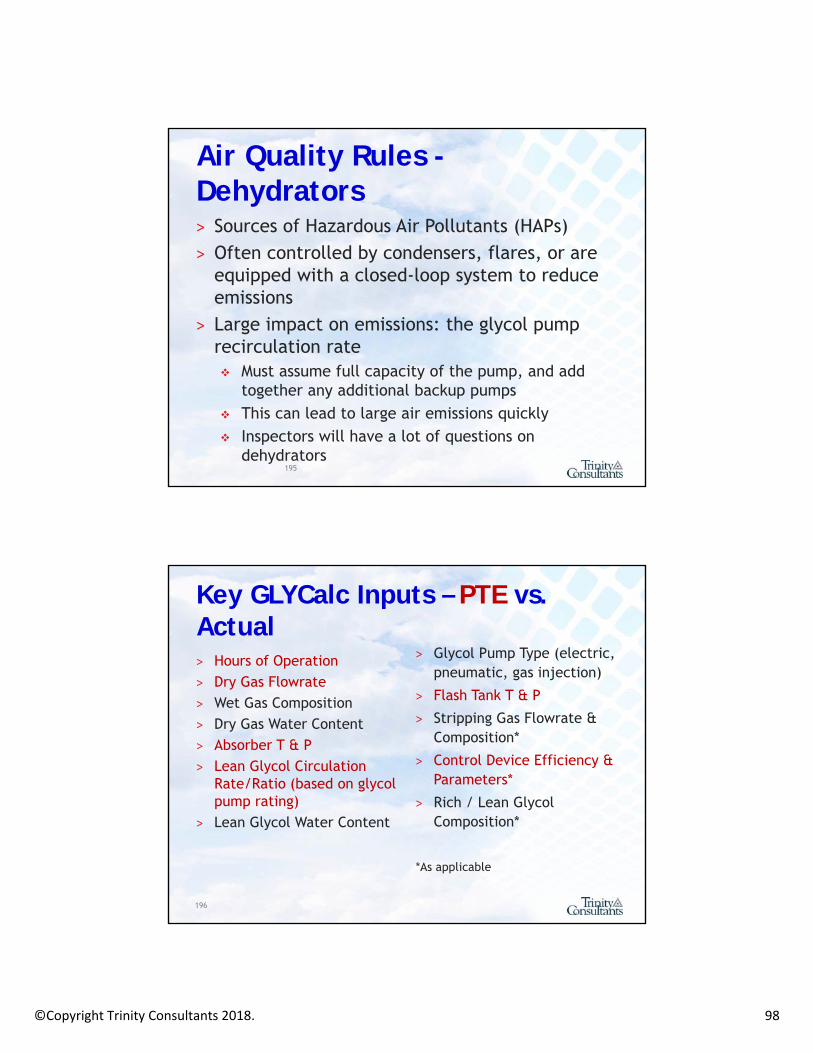
Air Quality Rules -Dehydrators˃ Sources of Hazardous Air Pollutants (HAPs)˃ Often controlled by condensers, flares, or are
equipped with a closed-loop system to reduce emissions
˃ Large impact on emissions: the glycol pump recirculation rate Must assume full capacity of the pump, and add
together any additional backup pumps This can lead to large air emissions quickly Inspectors will have a lot of questions on
dehydrators 195
Key GLYCalc Inputs – PTE vs. Actual˃ Hours of Operation˃ Dry Gas Flowrate˃ Wet Gas Composition˃ Dry Gas Water Content˃ Absorber T & P˃ Lean Glycol Circulation
Rate/Ratio (based on glycol pump rating)
˃ Lean Glycol Water Content
196
˃ Glycol Pump Type (electric, pneumatic, gas injection)
˃ Flash Tank T & P
˃ Stripping Gas Flowrate & Composition*
˃ Control Device Efficiency & Parameters*
˃ Rich / Lean Glycol Composition*
*As applicable

©Copyright Trinity Consultants 2018. 99
Gas Sampling
˃ Composition upstream of the contactor is needed as a critical input to GLYCalc
˃ Sampling location and method are critical˃ Collect sample from the inlet/wet gas line, downstream
from any inlet separator that removes liquids˃ Use GPA Method 2166: employs a manifold to remove
entrained liquids from the sample and a probe to collect the sample from the center of the gas line Liquids will bias the results, esp. BTEX
˃ This is NOT the same method often used to collect samples for Btu content or other properties
197
GLYCalc Tips and Tricks
˃ Worst-case emissions are not always achieved at the maximum throughput. Other operating conditions should be evaluated to determine PTE. Model is particularly sensitive to T & P and pump
rate Similarly, sometimes smaller dehys have greater
emissions
198

©Copyright Trinity Consultants 2018. 100
Air Quality Rules –Dehydrators – O&G Source Category˃ Each dehydration unit as follows
All large units (>3 MMscfd and >1.0 tpy benzene) Small dehy units constructed before 8/23/2011 are
existing Small dehy units constructed after 8/23/2011 are
new˃ Emission limits (§63.765) depend on proximity to urban
areas
199
Urban Areas – Definition(Based on 2000 Census Data)
˃ Urban Cluster: Population between 2,500 and 50,000 people
˃ Urbanized Area: Densely settled with at least 50,000 people
˃ Urban-1 County: Population >250,000 people
˃ UA plus offset and UC: The area occupied by each UA, UC (>10,000 people), and within 2 miles of each UA
200

©Copyright Trinity Consultants 2018. 101
Area Source Dehy Unit Requirements(UA + Offset & UC Boundary)˃ For large dehys, send still vent emissions:
to a control device via a closed vent system achieving 95% reduction, or 20 ppmv TOC/HAP;
or to control device via a closed vent system and reduce benzene emissions to < 1tpy.
˃ For small dehys, use the equation in the rule to establish the emission limit Meet the limit through a control device, process
changes, or show it meets the standard without control
˃ Monitor controls and keep records201
Area Source Dehy Unit Requirements(NOT in UA + Offset or UC Boundary)
˃ Determine optimum glycol circulation rate using rule equation - §63.764(d)(2)(i)
˃ Operate below optimum rate (or alternative rate via GLYCalc) - §63.764(d)(2)(ii)
˃ Recordkeeping and Initial Notification Requirements - §63.764(d)(2)(iii)
˃ Dehy units with actual annual average gas flow <3 MMscfd or actual benzene emissions <1.0 tpy are exempt
202

©Copyright Trinity Consultants 2018. 102
Dehydrators – Transmission & StorageNatural Gas T & S Facilities that:˃ Are major sources of HAP, and˃ Transport or store natural gas prior to entering the
pipeline to a local distribution company, or to a final end user (if there is no local distribution company)
˃ Note: A compressor station that transports natural gas prior to the point of custody transfer or to a natural gas plant is considered a part of the oil and gas production source category.
203
*Unlike Subpart HH, there are no requirements for Area Sources under this rule.
Dehydrators- Enforcement
˃ Yes. ˃ Often: misrepresentation of control
devices; or˃ Over-sized dehydrators that may be
processing small amounts of gas, but PTE emissions are high.
204

©Copyright Trinity Consultants 2018. 103
Activities Regulated by the Clean Air Act
Wellheads
©Copyright Trinity Consultants 2018. 104
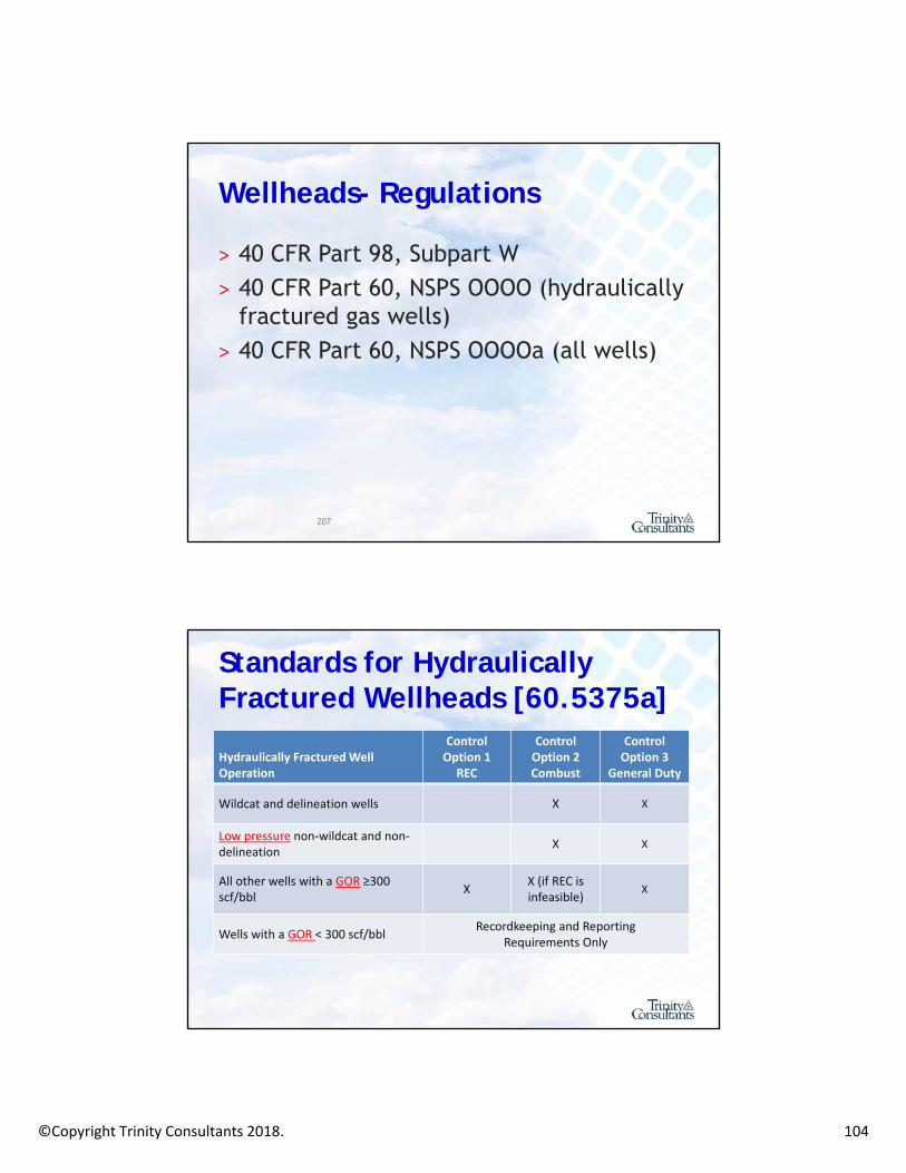
Wellheads- Regulations
˃ 40 CFR Part 98, Subpart W˃ 40 CFR Part 60, NSPS OOOO (hydraulically
fractured gas wells)˃ 40 CFR Part 60, NSPS OOOOa (all wells)
207
Standards for Hydraulically Fractured Wellheads [60.5375a]
Hydraulically Fractured Well Operation
ControlOption 1
REC
ControlOption 2Combust
ControlOption 3
General Duty
Wildcat and delineation wells X X
Low pressure non‐wildcat and non‐delineation
X X
All other wells with a GOR ≥300 scf/bbl
XX (if REC is infeasible)
X
Wells with a GOR < 300 scf/bblRecordkeeping and Reporting
Requirements Only

©Copyright Trinity Consultants 2018. 105
Wellhead Requirements – 3 in all [60.5375a]
1. REC - Perform reduced emissions completions/green completions:˃ During the initial flowback stage, route the flowback into one or more well
completion vessels or storage vessels and commence operation of a separator unless it is technically infeasible for a separator to function. Any gas present in the initial flowback stage is not subject to control under this section.
˃ During the separation flowback stage, route all recovered liquids from the separator to one or more well completion vessels or storage vessels, re-inject the liquids into the well or another well or route the recovered liquids to a collection system. Route the recovered gas from the separator into a gas flow line or collection system, re-inject the recovered gas into the well or another well, use the recovered gas as an on-site fuel source, or use the recovered gas for another useful purpose that a purchased fuel or raw material would serve. If it is infeasible to route the recovered gas as required above, route gas to combustion device. If, at any time during the separation flowback stage, it is not technically feasible for a separator to function, you must comply with requirements for initial flowback.
˃ A separator must be on-site for entirety of flowback period, with limited exceptions [NSPS OOOOa only]
2. Completions Combustion - Capture and direct recovered gas that cannot be directed to the flow line to a completion combustion device (unless risk of fire or explosion). It must be equipped with a reliable continuous ignition source.
3. General Duty - Maximize resource recovery and minimize releases to the atmosphere during flowback and subsequent recovery.
Wellhead Requirements – 3 in all

©Copyright Trinity Consultants 2018. 106
Wellhead Requirements-Controlling Flowback˃ Once enough gas is present to operate a
separator, route the recovered gas to: A gas flow line or collection system; Re-inject the gas into the well or another
well; or Use as on-site fuel source or other useful
purpose that you would purchase fuel for.
˃ If these options are technically infeasible, then you may combust.
Well Completion “To-Do” [60.5420a]˃ Submit advance notification to the
Administrator at least 2 days prior to the commencement of completion of an affected well. Anticipated date of well completion Contact information for owner/operator U.S. well number Latitude and longitude Planned date of the beginning of flowback
˃ States that already require advance notifications satisfy this requirement

©Copyright Trinity Consultants 2018. 107
˃ During completion, keep a daily log book with: Location API Well Number Date and Time of Flowback Date(s) and Time(s) to Attempt Separation Date and Time of Startup of Production Duration of Venting and Justification (or Deviation) Duration and Method of Recovery Duration of Combustion Deviations and Justification
Well Completion “To-Do” [60.5420a]
˃ Instead of recordkeeping on previous slide, for wellheads subject to both REC and completion combustion equipment, a digital photograph CANbe taken that contains: Date of photograph Longitude and latitude of the well site embedded
within or stored with the photograph (or separate GIS device visible in frame)
Picture of equipment for storing or re-injecting recovered liquid, equipment for routing recovered gas to gas flow line, and the completion combustion device connected to and operating at each completion operation
Well Completion “To-Do”

©Copyright Trinity Consultants 2018. 108
Well Venting for Liquids Unloading
Well Venting for Liquids Unloading˃ Subject to GHG reporting only (for now)˃ Track by well, by event˃ Tubing or Casing Diameter˃ Well Depth˃ Tubing Pressure or shut-in pressure
216

©Copyright Trinity Consultants 2018. 109
Well Testing Venting and Flaring
Well Testing Venting and Flaring˃ Subject to GHG reporting only (for now)˃ Track by well, by test˃ GOR˃ Number of days testing
218

©Copyright Trinity Consultants 2018. 110
Associated Gas Venting/Flaring
Associated Gas Venting/Flaring˃ Subject to GHG reporting only (for now)˃ Has traditionally been reported to be a
large source of emissions under GHG reports
˃ Extended flaring could be subject to state/local permitting requirements
˃ Includes: Wells that always vent associated gas; and Wells that vent associated gas during periods
of shut-ins or other upset conditions.220

©Copyright Trinity Consultants 2018. 111
˃ This is an evolving issue as Agencies learn more about scenarios causing venting and flaring.
˃ This could be broadly addressed through MSS permitting.
˃ Stay tuned.
221
Associated Gas Venting/Flaring
END OF SECTION 3
222

©Copyright Trinity Consultants 2018. 112
Section 4: Source Aggregation for Oil and Gas Facilities
223
Defining a “Facility”
˃ Three factor source determination Same two-digit standard industrial classification
(SIC) code; Common ownership or control; and Located on one or more adjacent or contiguous
properties.˃ “Adjacent” is used, but never defined. ˃ Rulemaking stems from years of litigation and
has resulted in another rule change (EPA’s Consistency Rules).
Copyright Trinity Consultants

©Copyright Trinity Consultants 2018. 113
˃ EPA has clarified “adjacent” in: Prevention of Significant Deterioration (PSD); Nonattainment New Source Review (NNSR); and Title V.
˃ The changes will impact operations with the Major Group SIC code of 13 (Oil and Gas Extraction) in states that opt to adopt these definitions.
Copyright Trinity Consultants
Defining a “Facility” for an Oil and Gas Site
˃ Two or more sources share the same two-digit SIC code (Major Group 13, “Oil and Gas Extraction”);
˃ Under common control; and ˃ Are contiguous or are located within ¼
mile of each other and have shared equipment.
˃ DOES NOT INCLUDE transmission and distribution under SIC Major Group 49.*
Defining a “Facility”
* States will still look at this case-by-case

©Copyright Trinity Consultants 2018. 114
https://www3.epa.gov/airquality/oilandgas/may2016/source-determination-fs.pdf
A
B
¼ mile
C ¼ mile
D
¼ mile
ExampleA and B same source since within ¼ mile and share equipment
C not same source since > ¼ mile from A and does not share equipment with B
D part of same source as A since within ¼ mile from A and shares equipment with A. Source is A, B, D
E
¼ mile
Source “E” is not in EPA’s provided scenarios

©Copyright Trinity Consultants 2018. 115
Source Aggregation: Moving Forward˃ Stay tuned- this will be an evolving issue.˃ Attend Trinity’s state-level events- the
impacts of these changes will vary from state to state.
˃ Know your state’s SIP.
229
END OF SECTION 4
230
©Copyright Trinity Consultants 2018. 116
Section 5: Case Studies and Discussion
Engine Rule Applicability –Engine Flow Charts˃ EPA’s engine rules are likely the most
complicated set of rules imaginable*˃ Facility is expected to install an engine
Facility is a HAP minor source Engine manufactured on June 30, 2008 450 hp
˃ What are the compliance requirements for the engine?
* Speaker’s opinion

©Copyright Trinity Consultants 2018. 117
˃ Engine is subject to MACT ZZZZ, which points us to NSPS JJJJ, which tells us the engine does not have any requirements. We call these magical engines “golden gap”
engines
233
Engine Rule Applicability –Engine Flow Charts
˃ Facility is expected to install an engine Facility is a HAP minor source Engine manufactured on July 2, 2008 450 hp
˃ NOW what are the compliance requirements for the engine?
234
Engine Rule Applicability –Engine Flow Charts

©Copyright Trinity Consultants 2018. 118
˃ Subject to emission standard requirements˃ Compliance requirements
Initial performance testing Ongoing emission testing
˃ Monitoring requirements˃ Notification requirements˃ Recordkeeping requirements
Maintenance records
˃ Reporting requirements
235
Engine Rule Applicability –Engine Flow Charts
Calculating Potential to Emit
˃ An engine is subject to NSPS JJJJ, which requires a catalyst.
˃ When looking at emissions for permitting, do you use the pre-catalyst emissions data, or post-catalyst emissions data?
236

©Copyright Trinity Consultants 2018. 119
˃ Use post-catalyst emissions to determine the PTE. The catalyst (and associated emission
reduction) is required by a federally applicable NSPS.
˃ Pro: lower level permitting!˃ Con: NSPS compliance requirements.
237
Calculating Potential to Emit
˃ An engine is NOT subject to NSPS JJJJ. ˃ Without a catalyst, emissions are above
100 tons per year CO. ˃ Can you install a catalyst to reduce
emissions and base your permit determination on post-catalyst emission data?
238
Calculating Potential to Emit

©Copyright Trinity Consultants 2018. 120
˃ No. The catalyst is not required due to a federal requirement or a permit. You must look at the pre-catalyst emission rate to determine the PTE.
˃ However- you can get a permit with a condition that requires the catalyst, and permit the site as a “synthetic minor.”
239
Calculating Potential to Emit
Modifying a Wellsite
˃ A well is drilled after 9/18/2015 on a pad with only wellheads.
˃ The well feeds into a centralized tank battery.
˃ Where should the LDAR surveys be performed?

©Copyright Trinity Consultants 2018. 121
˃ A wellsite that contains only wellheads is not affected.˃ Well site means one or more surface sites that are
constructed for the drilling and subsequent operation of any oil well, natural gas well, or injection well. For purposes of the fugitive emissions standards at §60.5397a, well site also means a separate tank battery surface site collecting crude oil, condensate, intermediate hydrocarbon liquids, or produced water from wells not located at the well site (e.g., centralized tank batteries).
˃ LDAR is required at the tank battery only.
Modifying a Wellsite
Compressor Station
˃ Existing natural gas transmission compressor station
˃ Addition of reciprocating compressor unit after 9/18/2015 that was manufactured <8/23/2011
˃ No compressors were removed as part of the project

©Copyright Trinity Consultants 2018. 122
˃ Only evaluate “new” sources Compressor and driver (if applicable)
˃ Site installed a compressor that is new to the facility, but not new for purposes of NSPS
˃ Compressor has no rod packing replacement requirements because of manufacture date before 9/18/2015
˃ Site is subject to LDAR because the addition of a compressor triggers “modification”
Compressor Station
H2S Treatment Example
˃ Facility is constructed after 9/18/2016˃ Facility consists only of a sulfur scrubbing
device and two compressors˃ Is the sulfur scrubbing device considered
a “sweetening unit” at a natural gas processing plant?
˃ Is the facility subject to the LDAR requirements for gas processing plants?
244

©Copyright Trinity Consultants 2018. 123
Gas Processing Facility
˃ What is a “Gas Processing Plant?” NSPS OOOO and OOOOa: “any processing site
engaged in the extraction of natural gas liquids from field gas, fractionation of mixed natural gas to NGL products, or both. A JT valve, a dew point depression valve, or an isolated or standalone JT skid is not a natural gas processing plant.”
245
˃ Subpart KKK – Standards of Performance for Equipment Leaks of VOC from Onshore Natural Gas Processing Plants for Which Construction, Reconstruction or Modification Commenced After January 20, 1984, and on or before August 23, 2011
Gas Processing Facility
246

©Copyright Trinity Consultants 2018. 124
Gas Processing Facility
˃ What is “Gas Sweetening?” Sweetening unit means a process device that
removes hydrogen sulfide and/or carbon dioxide from the sour natural gas stream.
˃ What is a “Gas Processing Plant?” “any processing site engaged in the extraction of
natural gas liquids from field gas, fractionation of mixed natural gas to NGL products, or both. A JT valve, a dew point depression valve, or an isolated or standalone JT skid is not a natural gas processing plant.”
247
˃ No to both. The facility does not meet the definition of natural gas processing, therefore the amine unit is not subject, and the components are not subject to gas processing LDAR provisions.
˃ HOWEVER, the facility will be subject to LDAR requirements for compressor stations or well sites.
248
Gas Processing Facility
©Copyright Trinity Consultants 2018. 125
Compressor Case Study
˃ A compressor manufactured and installed in 2008 is sold to another company.
˃ Upon receipt of compressor on October 15, 2012, new company simply installs and commences operation.
˃ Is this compressor subject to NSPS OOOO?˃ Is the station subject to LDAR?
249
Relocation
˃ As found in existing NSPS, the following actions (by themselves) are not considered modifications [§60.14(e)]: The relocation or change in ownership of an
existing facility.
˃ How can relocation be proven? Tracking life of a piece of equipment; Manufacture date may not provide total
protection.
250

©Copyright Trinity Consultants 2018. 126
˃ No- the compressor is not subject to requirements under NSPS OOOO or OOOOa for compressors.
˃ Is the station subject to LDAR? No, even if the addition of the compressor
results in a net compression horsepower increase, the date of installation was <9/18/2015
Compressor Case Study
Reconstruction Case Study
˃ A compressor is manufactured before 8/23/2011
˃ In 2013, the compressor is damaged˃ In 2016, the damaged compressor is sold
to another company˃ The company repairs the compressor to
get the unit functioning again˃ Is this unit subject to NSPS OOOO?
252

©Copyright Trinity Consultants 2018. 127
Routine Repair and Maintenance
˃ Routine Repair and Maintenance is not a Modification
˃ ‘‘Maintenance, repair, and replacement which the Administrator determines to be routine for a source Category.” [§60.14(e)(1)]
˃ How should a company demonstrate “routine maintenance, repair, and replacement”?
253
Reconstruction…˃ 50% Rule: how much $$ was spent?˃ Is it cumulative? EPA is not consistent.˃ Is it back to promulgation of NSPS, or back to birth?˃ Reference Documents!
“when the extent of repairs goes beyond the normal maintenance activity necessary to maintain a boiler’s useful life, resulting in substantial life extension, the costs should be aggregated to determine if the repairs constitute re-construction.” (12/28/1992, Reconstruction of Subpart Dc Boiler)… or….
Conclusion: Amending Section 60.15 to authorize unlimited aggregation would best advance the purposes of Section 111. The current wording of Section 60.15 permits only the more limited policy of aggregating replacement costs stemming from what may be viewed objectively as a single planning decision.
254

©Copyright Trinity Consultants 2018. 128
Demonstrating “Routine”˃ Document, document, document
Manufacturer’s Data
˃ Check the ADI Tricky because sources are previously un-regulated
˃ Industry Trade Groups API, local O&G associations May be difficult to reach consensus
˃ Individual Company Case-by-Case May be unpalatable/unreasonable across large
geographic areas May be difficult to reach consensus
255
Examples?

©Copyright Trinity Consultants 2018. 129
Questions?
Presenter’s Contact Information
Georgette Reeves, Director- Oil and Gas Sector Services [email protected]
Dallas Headquarters12700 Park Central Dr.| Dallas, TX 75251
(972) 661-8100 or 800-229-6655
Visit us online at TrinityConsultants.com or scan the QR code with your smart phone.