0 . ~, '1)11 - fUZE - National Criminal Justice Reference ... GRENADE FUZES Impact Inertia Base...
194
--r " \ 0 ." '1)11 1/ • I -- I ! I l " c .. \) POLvlCE fECHNICAL SEAlES "INTERNATIONAL ASSOCIATION OF CHIEFS OF POLICE, INC. "'GAITHERSBURG, MARYLAND f) ,;., 1.0;.. •• .' f. .' . '. .,:. . .,! . o o o If you have issues viewing or accessing this file, please contact us at NCJRS.gov.
Transcript of 0 . ~, '1)11 - fUZE - National Criminal Justice Reference ... GRENADE FUZES Impact Inertia Base...

--r " \ 0
." ~,
'1)11
1/
•
I --I !
I l ~,
" c .. \) POLvlCE fECHNICAL SEAlES 03~1
"INTERNATIONAL ASSOCIATION OF CHIEFS OF POLICE, INC.
"'GAITHERSBURG, MARYLAND
f)
,;., 1.0;.. •• .' f. .' . '. .,:. . .,! .
o
o
o
If you have issues viewing or accessing this file, please contact us at NCJRS.gov.
.,
u.s. MILITARY ORDNANCE COLOR CODES
~--------.~--~~-----------------------~-BODY COUOR
Markings in
Red, Green or Black
nnarkingsin Black
.. ':' " Ii . ':.J ,f9tai'l~ings i~, EUilok . , " ::' . 0t\\%1JiJl(b
Markings in Black
Markings in Black Except
for WP and PWP Which
Are
Markings in Black
EARLY COLOR CODE RECENT COLOR CODE
High Explosive (HE) High Explosive (HE)
High Explosive Anti-Tank (HEAT) High Explosive Plastic (HEP)
High Explosive Plastic (HEP) Illuminating
Chemical (War Gas)
Smoke
Illuminating
Practice
Drill
Armor Piercing
APERS
High Explosive
Practice
Not Used
Not Used
Illuminating
APERS
Canister
Chemical (War Gas)
All Armor Defeating
High Explosive
Practice
Chaff
Incendiary
Smokes
Illuminating

I_ I
L, __ _
PART I HAND AND RIFLE GRENADES
INTERNATIONAL ASSOCIATION OF CHIEFS OF POLICE, INC.
RESEARCH DIVISiON
Eleven Firstfield Road _ Gaithersburg, Md. 20760 Area Code 301-Telephone 948-0922

This document was produced as part of the information dissemination service of the National Bomb Data Center conducted by the International Association of Chiefs of Police, Inc. for the U.S. Department of Justice under contract J-LEAA-OJ8-70.
Persons undertaking such projects under government sponsorship are encouraged to express freely their professional judgments, findings, and conclusions. Therefore, points of view or opinions stated in this document do not necessarily represent the official position or policy of the U.S. Department of Justice.
L __________________________ _

Table of Contents Section Topic Page
ONE HAND GRENADES ......••....•.......................... 2 HAND GRENADE FUZES. . . . . . . . . . . . . • . . . . . . . . . . . . . . . . . 4
Striker Release Delay PU" Friction Delay Percussion Delay Match Head Delay I mpact Non-Delay
Electr3cal Fuzes All Ways Action I mpact Fuzes Impact Inertia Base Fuzes
ImpiOvised Grenade Fuzes BURSTING HAND GRENADES ........................... 34
Fragmentation Externally Serrated Body Heavy Cast I ron Body Heavy Cast I ron Body with I nternal Serrations Cast Aluminum Body with Visible Ball Bearings Embossed Steel Body Smooth Steel Body "Tin Can" or Light Sheet Metal Body Plastic or Bakelite Body Ceramic or Glass Body Cloth, Canvas, or Fiber Body I mprovised Fragmentation Grenades
Chemical Agent Delivery U.S. Military ABC-M25A2 Penguin Baseball Grenade Federal and Lake Erie Bursting Grenades

Smoke (White Phosphorous) U.S. M15 and M34 WP Grenades U.S. BLU-17/B Smoke Bomb (WP)
Incendiary (Napalm) U.S. Military Napalm Grenade Burnol Backfire Grenade Improvised Bursting Incendiary Grenade (Sterno)
Anti-Tank (HEAT) Soviet RPG-43 and RPG-6
Marine Marker U.S. MK 1 MOD 3
Anti-Swimmer Netherlands Model G4
Hand Grenade Simulators M80 Explosive Simulator M116A 1 Hand Grenade Simulator M115A2 Artillery Projector Ground Burst Simulator
BURNING HAND GRENADES ........................•.. 79 Chemical Agent Delivery
Beer Can Body Rubber Ball Body Miniature Body
Smoke (Screening and Signaling) Beer Can Body Miniature Body Improvised
Incendiary U.S. Military AN-M14 TH3 Improvised Incendiary Grenades
Illumination EJECTION HAND GRENADES ........•.•..•.•..•.•..•... 108
Chemical Agent Delivery AAI Multipurpose Grenade Lake Erie Exit Port Grenades
Smoke FRANGIBLE HAND GRENADES .....................•... 112
Incendiary (Molotov Cocktail) U.S. Military Frangible Incendiary Grenades British No. 76 Mk I Japanese Frangible I ncendiary Grenades I mprovised Molotov Cocktails
Smoke German Model 1 Hand 2H Japanese Smoke Grenade
Toxic Gas Japanese Toxic Gas Frangible Grenade Improvised Gas Grenade

L
TWO RIFLE GRENADES ........................•............. 131 RIFLE GRENADE LAUNCHERS ........................ 132
Spigot Launchers Cup Launchers Rod Launchers Hand Grenade Adapters
RIFLE GRENADE FUZES Impact Inertia Base Detonating Fuze Point Initiating Base Detonating Fuze
Mechanical PIBD Fuze Electrical PIBD Fuze
138
BURSTING RIFLE GRENADES ........................ 142 Anti-Tank (HEAT)
U.S. M31 U.S. M28 U.S. M9A1
Smoke (WP) U.S. M19A1
Air Burst Simulators U.S. M27A 1 B1
BURNING RIFLE GRENADES .......................... 148 Smoke
U.S. M22 and M22A 1 U.S. M23 and M23A 1
EJECTION RIFLE GRENADES. . . . . . . . . . . . . . . . . . . . . . . . .. 149 Illumination and Signaling
U.S. Signal, Illuminating Cluster and Parachute U.S. Signal, Smoke
THREE PROJECTED GRENADES .................................. 155 JAPANESE GRENADE DISCHARGER SYSTEM ............ 155 SOVIET RPG RECOILLESS GRENADE LAUNCHER SYSTEM. 156 U.S. 40MM GRENADE LAUNCHER SYSTEMS. . . . . . . . . . . . .. 159
Bursting Fragmentation Grenades Helicopter-Fired Bursting Smoke (WP) Grenade Burning Tear Gas (CS) Grenade Ejection Signaling and Illumination Grenades Colored Smoke Signaling Grenades Multiple Projectile Cartridge
THE POLICE 37/38MM RIOT GAS GUN SySTEMS .......... 174 Bursting Projectiles Burning Projectiles
IMPROVISED PROJECTED GRENADE SYSTEMS .......... 176 CO 2 Cartridge Projected Grenades Explosive Arrow Grenades Explosive-Filled Pistol-Launched Grenades Shotgun-Launched Fire Bomb
INDEX ....... , . . . . .. •. . . .. . . • . .. . .. . • . . . . . . . .. . . . . . . .. . . . . .. PART"
ii
RECOGNITION OF EXPLOSIVE AND INCENDIARY DEVICES
PART I. Hand and Rifle Grenades
The purpose of this publication is to provide public safety personnel with information on the key identification features of commonly encountered types of explosive and incendiary devices. While constnlction and functioning detail is frequently provided, these data are included only to facilitate recognition. Attempts to dismantle or render safe these devices should be made only by fully qualified bomb technicians.
This publication has been divided into two parts: Part I Hand and Rifle Grenades Part II Land Mines, Artillery, Mortar, and Rocket Projectiles
Within each part are sections which cover those classes of military, commercial, and improvised explosive and incendiary devices that are most likely to be encountered by public safety personnel. The approach throughout has been to provide recognition data. However, it should be noted that some devices will not possess the common or general identification features normally associated with their particular classification. Although there will always be these exceptions to general identification nlles, such cases are rare and any unidentified device can and should be treated as explosive and dangerous.
Military or commercial ordnance items and improvised or homemade explosive and incendiary devices generally consist of three major parts or components: the/uze, the body, and the/iller. It is by correct visual recognition and evaluation of the first two of these components that a correct identification of the item is made. Careful observation of the fuze and the body of an item of ordnance should, in most cases, enable the investigator to determine the method of functioning of the fllZ~ and the effect produced by the detonation or ignition of the device. Correct identification of these two components may lead to a general or specific identification of the type of filler. As a practical matter, however, the non technician public safety officer is only concerned with recognition to determine:
• Is the suspicious object an explosive or incendiary device (bomb)?
• What risk of injury or property damage is involved?
• How can risk be reduced pending arrival of explosive disposal personnel?
While this series of publications' should assist in the recognition of most devices, no individual is Ukely to be able to correctly identify or recognize all ordnance items. Since recognition ability is an acquired skill, it must be constantly exercised or the skill deteriorates. Where rare or unusual items are discovered and time permits, the Research Division of IACP will provide technical assistance in recognition and identification of explosive and incendiary devices. Should such technical assistance be desired, it is recommended that initial contact be established via telephone in order to insure that photographic and measurement criteria are mutually understood.
I

-------------------------~--------
SECTION ONE HAND GRENADES
Although grenades have been employed since about 250 B.C., when the Romans used hand grenades filled with Greek fire (a smoke and incendiary mixture) to combat the elephant charges of the King of Epire, it was not until 1904-5, during the Russo-Japanese War, that they achieved general recognition as a basic weapon of war. Hand and rifle grenades were employed in great numbers by all participants in World War I and since that time grenades have become a standard item of mihtary ordnance, second only in importance to small arms weapons. Almost all nations have some form of manufactured grenade in their military arms inventory. Foreign and domestic revolutionary groups also recognize the need for weapons of this sort and will usually attempt to improvise some type of hand grenade. Because of their military and revolutionary applications and their popularity as souvenirs, the public safety officer may find that hand grenades are regularly encountered in the course of his duties.
Hand grenades, as the name implies, are designed to be thrown to their target by arm power. A soldier is expected to be able to throw a hand grenade a distance of 20 to 35 yards with reasonable accuracy. In order to accomplish this, the grenade must conform to certain design characteristics. For example, it should:
• Be of a size and shape easily, comfortably, and naturally held in the hand. A ball, beer can, or large lemon shape is characteristic.
• Weigh not more than 2Yz pounds and ideally 1 pound or less.
• Have a fuze that provides a short time delay. Because the grenade will burst, burn, or eject, the length of delay time provided by the fuze should vary from approximately 3 10 5 seconds. A short delay time is necessary so that the grenade cannot be thrown back or ailow time for the enemy to seek protective cover.
• Be easily thrown. If the hand grenade is to be used by a nation where throwing a ball is not a common childhood experience, a throwing stick may be attached to the body of the gl·enade as an aid to achieving additional range and/or accuracy. This stick, however, will make the hand grenade more awkward to carry and will present problems when thrown in the bush or jungle.
The vast majority of hand grenades manufactured since World War I will possess these design characteristics which, therefore, may serve as an aid to identification. Figure I illustrates typical hand grenade shapes and configurations.
Hand grenade') are essentially a delivery system by which some material is transported to a desired target. While the material delivered may range from high explosive fragmentation to a relatively harmless smoke or dye, the actual delivery takes place in one of four basic grenade functioning modes. The grenade, whatever its payload or construction, either (1) bursts, (2) burns, (3) ejects, or (4) shatters.
2
I--~·
JAPANESE TYPE 98
FRAGMENTATION
!J
SOVIET RKG·3M HEAT
IMPROV'SF.D BURNING
INCENDIARY
I i i I
II
U.S. AN·M 14
IMPROV;SED IMPROVISED PIPE GRENADE INCENDIARY
FRAGMENTATION
I I I
II
U.S. MK2 FRAMENTATION
U.S. ABC·M25A2 BURSTING CHEMICAL
(CS)
VIET CONG BURSTING
CHEMICAL CS U.S. M33
FRAGMENTATION
GERMAN BURNING INCENDIARY MODEL 39 VIET CONG FRAGMENTATION
FRAGMENTATION FRAGMENTATION ® NEIOe.,
,------------------------------------------."--------~. Figure 1
TYPICAL HAND GRENADE SHAPES

•
•
•
A hand grenade that bursts produces blast pressure which may be used alone, as in concussion or shaped charges, or to propel fragmentation or disseminate other materials such as chemical riot control agents, smoke, dye, and incendiary mixtures. In World War I, bursting hand grenades were also used to deliver toxic war gases.
A hand grenade that burns may produce an extremely hot incendiary effect or disseminate chemical riot control agents, smoke, or illumination visible either to the naked eye or on infrared scopes .
The ejection hand grenade employs the pressure of gases produced by a small explosive charge to eject the grenade's payload through vents, ejection holes, or blow-out ports. Although a controlled explosion takes place, it is confined within the grenade and the body does not rupture or fragment in normal operation .
The hand grenade that shatters or breaks as a result of impact with the target area is known as a frangible grenade. Frangible grenades are designed to shatter on impact in order to disseminate th~ir payload. An example of this type of grenade would be the simple Molotov cocktail.
Of the four basic classes of grenades, the bursting munition presents the greatest threat of injury or death from mishandling. Unfortunately, later designs of bursting grenades, especially the extremely lethal fragmentation variety, are difficult to identify. Public safety personnel whose military experience dates back to World War II or the Korean conflict may be unpleasantly surprised to find that contemporary devkes bear little resemblance to the familiar "pineapple" fragmentation grenades of the past.
If.h:.cause of the unusually high risk associated with bursting grenades, a simple screening procedure is recommended for field application by nontechnical personnel. This tentatil1e identification procedure is based on the absence of vents, ejection holes, or blow-out ports on burstin.g and frangible grenades. These key identification features are illustrated in Figure 2. Thus, any grenade without vents should be considered a bursting grenade and handled accordingly. The very small number of frangible grenades encountered can be te1ltatively and erroneously identified as bursting munitions without undut> risk or inconvenience.
Hll.ND GRENADE FUZES
Hand grenade fuzes must be fairly simple in operation, because the person using the hand grenade must generally arm the fuze with one hand and throw the grenade with the other. The two most commonly employed types of hand grenade fuzes in use today are the striker release delay fuze and the pull friction delay fuze. The vast majority of hand grenade fuzes are of the delay functioning type employing a simple pyrotechnic (burning) delay element which provides a period of time for the hand grenade to travel from the thrower to the target area. Mass-produced military and civilian hand grenades cf the bursting type will usually employ a delay time of 3 to 5 seconds, while those designed to burn usually employ a shorter delay of 2 to 3 seconds. The improvised fuzes usually employed with homemade grenades vary widely in quality and reliability and the delay times provided depend entirely upon their construction.
4

VENTS .----~"\ -"I - ,/'!/ ~ .1' ...... "'"
BLOWOUT r(~~ .-~-- 1. fu / PORT 0 (~i. . .',\\ r /
n---';~"'T""""'I11 ? y-~ 0 ,v-- JV"r--/, :J'-A) _ ... l" 0 ~r "'\ ~ )-0 .., ,
.::.:~ 7:/); 0 0 ~~~~~}IJ re-0 ~!'5 . . '-. '-f • . ~h nj[1 \,-J
U-~"""':L-.I~ ,;<"-/./ ~~. ~ AGENT EJECTION DISSEMINATION '~~,_,I'-_~r~,-
AN EXPLOSIVE FORCE PROVIDES ENERGY TO EJECT MICROPULVERIZED CHEMICAL AGENT FROM EXIT PORTS BUILT INTO THE GRENADE BODY .
o o o
, r ,~
.J ':.); ~\ ')~. -J I'Il . J~~'-'
r j I "I ,.., J(" ~ h --<'-"lS) t-... ,r:) c r-: ) [ ~ - ""
d .\ ,.,..-v-j~J ~.:> ~ ~ r~ ~ '-i. v e,'~' h ?::- 't.--.
'- 'C/' ~'t.... _?:?~ _-
BURNING DISSEMINATION ""'---- fi\ AN AGENT / FUEL MIXTURE IS BURNED TO RELEASE ACTIVE CHEMICAL '§! AGENT AND SMOKE CLOUD FROM EXIT PORTS ON THE GRENADE BODY. NBDC
Figure 2 TYPICAL HAND GRENADE VENTS,
EJECTION HOLES, AND BLOW-OUT PORTS
Striker Release Delay Fuzes
A typical striker release delay fuze consists of a small-arms primer placed over a short length of black powder-filled safety fuse. Attached to the lower end of the safety fuse is a detonator (blasting cap) which is surrounded by the explosive charge designed to burst the hand grenade body. When striker release delay fuzes are used in burning hand grenades, the detonator is replaced by an iti~nition mixture that starts the burning action.
A spring-loader striker (firing pin) is employed to fire the primer and start the safety fuse burning. This spring-loaded striker is usually held in a cocked position by a safety lever which acts as a positive block preventing the striker from moving toward the primer until it is removed. The safety lever is positively held in position by a safety pin (cotter key) which has a pull ring attached. Construction details of striker release delay fuzes are illustrated in Figure 3.
To employ the standard U.S. striker release delay fuzed hand grenade, the grenade is held in the right hand with the palm of the hand over the safety lever. With the left hand, the pull ring is pulled to extract the safety pin from the grenade. Removal of the safety pin requires a pull 10 to 40 pounds. Even when the hand grenade fuze is armed, the delay will not begin to function until the safety lever has been released and the striker allowed to impact the primer. This normally happens
5
PRIMER
DELAY ELEMENT
BLASTING CAP
_SAFETY LEVER
U.S. STRIKER RELEASE DETONATING FUZE
STRIKER-
PRIMER
BLASTING CAP
VIET CONG STRIKER RELEASE FUZE
PRIMER---'H \WnUl.._STRIKER SPRING
DELAY ELEMENT
STRIKER
, __ SAFETY LEVER
PYROTECHNIC IGNITER
~-_STRIKER SPRING
PRIMER---+ot..J
DELAY ELEMENT
IGNITION MIXTURE
r--~",,"
STRIKlER
SAFETY LEVER
U.S. STRIKER RELEASE IGNITION FUZES
STRIKER SPRING
~~~--SPRING
..wt-:-.++---+,~- STRIKER
.. .--~BLASTING CAP
_I~H~-PRIMER DELAY
'-10114~~-ELEMENT
BRITISH "MILLS BOMB" NO. 36 M STRIKER RELEASE FUZE ®
NBCC
Figure 3 CONSTRUCTION DETAI LS OF TYPICAL STRIKER
RELEASE DELAY FUZES EMPLOYED IN HAND GRENADES
6

i
I
I-I
when the grenade is released from the hand, as illustrated in Figure 4. Should the holder decide not to throw the hand grenade, the safety pin may be reinserted, returning the fuze to a safe condition.
Typical striker release delay fuzes employed by the military of various nations are illustrated in Figure 5. Although different in appearance, the basic design of these fuzes remains the same. The striker is held by the safety lever which is in turn restrained by a safety pin with a pull ring attached. The striker release hand grenade fuzes illustrated are from the areas of the world where returning U.S. servicemen may have acquired them as souvenirs. The French hand grenade, known as the "little brown jug" because of its shape and paint color, is unique in that while the safety lever restrains the striker, when the hand grenade is thrown the safety lever moves outward, releasing the striker, but remains attached to the fuze body and travels to the target with the hand grenade. Striker release delay fuzes of U.S. military design are also used on commercial tear gas and smoke grenades commonly encountered in this country.
A variation of the standard striker release delay fuze is employed in the U.S. ABC-M25A2 tear gas grenade. This grenade, illustrated in Figure 6, has an internal fuze arrangement activated by the release of a spring-loaded slider which travels the length of the burster well to impact on a firing pin at the bottom of the well, exploding the detonator after a 1.4- to 3-second delay.
SAFETY LEVER RELEASING STRIKER AS GRENADE IS THROWN
~
\ SAFETY PIN BEING REMOVED, \ SAFETY LEVER RESTRAINS STRIKER
Figure 4 ARMING AND THROWING SEQUENCE FOR A U.S. STRIKER
RELEASE DELAYED FUZED M26 FRAGMENTATION HAND GRENADE
7
® NBDC

----.--------------------
MARKINGS SOMETIMES FOUND HERE
SOVIET UNiON AND SATELLITE COUNTRIES, CHINESE COMMUNIST, NORTH KOREAN, VIET CONG MODEL F·l FRAGMENTATION
U.S. M 26 FRAGMENTATION
MARKINGS SOMETIMES FOUND HERE
SOVIET UNION AND SATELLITE COUNTRIES, CHINESE COMMUNIST, NORTH KOREAN, VIET CONG MODEL RG·42 FRAGMENTATION
BRITISH "MILLS BOMB"
MARKINGS SOMETIMES FOUND HERE
NO. 36 M FRAGMENTATION FRENCH, LlTILE BROWN JUG, FRAGMENTATION
Figure 5 STRIKER RELEASE DELAY FUZES IN USE TODAY
if a hand grenade has been employed in a bombing attack, the investigator will usually find the safety lever or arming sleeve in the crime scene area. U.S. military safety levers have markings indicating the model of the fuze, the lot (identification) number, and the date of manufacture which may provide investigative leads. The pull ring and safety pin (cotter key) are usually retained by the bomber but may be found discarded nearby or may be recovered from a suspect's pockets or vehicle. Component parts of U.S. military striker release delay fuzes which may be recovered by the investigator are illustrated in Figure 7.
8

ARMING SLEEVE
~~I;:::l~~ ~RETAINER PIN FIRING SPRING
PLASTIC FILLER PLUG
SLIDER ASSEMBLY FIRING PIN
WITH PRIMER, DELAY ELEMENT AND DETONATOR
Pull Friction Delay Fuzes
MILITARY ABC·M25A2 BASEBALL GRENADE
Figure 6 THE ABC·M25A2 GRENADE FUZE
® NBDC
The pull friction delay fuze ranks as the second most commonly used type of hand grenade fuze in the modern military world. This type of fuze is usually selected by newly emerging nations as their standard hand grenade fuze because of its simplicity and ease of construction. The fuze body may be easily manufactured by simple pot metal or lead casting techniques, and assembly of the fuze is easy and inexpensive when primitive assembly line techniques are employed. The fuze consists of a wire coated with an abrasive compound which is pulled through a small container of match head composition. Movement of the wire causes the match head composition to ignite and the resulting flame is used to light a short length of safety fuse. The safety fuse burns down into a detonator in the bursting hand grenadt ;., '., an ignition mixture if the hand grenade is of the burning type. The abrasive-coated pull wire, 11.:.Lch head composition, safety fuse, and detonator or ignition mixture are encased or sealed within the metal fuze body. Figure 8 illustrates a typical pull friction delay fuzed hand grenade construction.
Pull friction delay fuzes are most commonly used in hand grenades with a throwing stick. The fuze is assembled so that the detonator or igniter is in contact with the filler. A pull string is
9
----------------------------------- -

LOT NUMBER DATE OF MANUFACTURE
MARKINGS ARE PAINTED ON OR METAL STAMPED INTO SAFETY LEVER
CURVE INDICATES ___ BURSTING HAND_ GRENADE FUZE
PULL RING-
Figure 7
\
LONG STRAIGHT SAFETY LEVER INDICATES BURNING HAND GRENADE fUZE
SHORT ANGLE INDICATES BURSTING HAND GRENADE FUZE
® Nacc " SAFETY PIN
RECOVERED CRIME SCENE ITEMS INDICATING USE OF U.S. STRIKER RELEASE DELAY FUZED HAND GRENADE
generally tied to the pull wire and passed through a hole in the throwing stick. The lower end' of the pull string is tied in a loop or has a ring, knob, or button attached and is packed into an enlarged hole in the lower end of the throwing stick. A plug or cap insures that the pull string is safely stored until the time when the hand grenade is to be used. In throwing the hand grenade, the throwing stick is held in the right hand and the plug or cap is removed from the lower end of the handle allowing the pull string to drop out. The pull string is grasped in the left hand, and when ready, the string is pulled sharply and the hand grenade thrown as illustrated in Figure 9.
If a hand grenade having a pull friction delay fuze is employed in a bombing, the pull string and attached pull wire (if it came out of the hand grenade) usually will not be found in a search of the immediate crime scene area. Having pulled the pull string and thrown the hand grenade, the bomber, because the pull string is in his hand, will generally carry it away with him when he leaves the area. The pull string, however, may be discarded within 1 or 2 blocks of the scene or left in clothing or vehicles. The closing cap or plug from the handle of the throwing stick will generally be found in the immediate bomb scene area. Component parts of a pull friction delay fuzed hand grenade dropped or thrown away by the bomber which may be recovered in or near the crime scene are illustrated in Figure 10.
10

SAFETY FUSE ABRASIVE COATED PULL WIRE
:-~ETON;OR -I I I I /1 I SEALED WITH I I WAX OR TAR I -----_.- MATCH HEAD
COMPOSITION
PULL STRING
VIET CONG/CHINESE COMMUNIST/NORTH KOREAN
Percussion Delay Fuzes
Figure 8 CONSTRUCTION DETAILS OF A TYPICAL
PULL FRICTION DELAY FUZE
The percussion delay fuze is in limited use by the military nations of the world and is used on one U.S. commercial tear gas grenade. This fuze consists of a primer positioned so as to ignite a short length of safety fuse which burns down into a detonator or ignition charge. These components are sealed into the metal body of the hand grenade fuze. A striker is positioned over the primer and is held away from the primer by a lightweight spring. A safety pin is passed through the striker or between the striker and the primer, preventing accidental firing of the fuze. In place of a safety pin, some percussion fuzes use a safety cap placed over the striker to prevent accidental firing. Typical construction details of percussion delay fuzes are illustrated in Figure II.
When the percussion delay fuzed hand grenade is to be used, the safety pin or safety cap is removed and the fuze striker plunger is sharply struck against a hard object such as a rifle stock or tree trunk. This impact drives the striker plunger onto the primer, causing it to fire. The hand grenade is then thrown to the target. This sequence of operation is illustrated in Figure 12. Various hand grenades using the percussion delay fuze are illustrated in Figure 13.
If a percussion delay fuzed hand grenade is used in a bombing action, the safety pin or safety cap may be found in the crime scene area.
11
II

PULL FRICTION DELAY FUZE PULL WIRE
HOLLOW THROWING STICK
WAXED PAPER DISC
PULL STRING
PULL RING
,
Figure 9 ARMING AND THROWING SEQUENCE OF A
PULL FRICTION DELAY FUZED HAND GRENADE
Match Head Delay Fuzes
® Nacc
The match head delay fuze consists of a large match head placed on top of a length of safety fuse. Striking a scratch board across the match head causes it to flare and ignite a short length of safety fuse which burns down and detonates the blasting capor ignites a burning compound.
Figure 14 illustrates two hand grenades with a match head delay fuze. The Japanese pottery hand grenade is of the bursting type having a detonator (blasting cap) and an explosive charge. The U.S. "mini" hand grenade employs a 35 mm film can for a body and is of the burning type producing smoke or tear gas.
This type of hand grenade fuze is limited to military usc iil the U.S. "mini" smoke and riot grenades employed in Southeast Asia. This fuze is very easy to construct and quite reliable in use and would be very simple to employ as a delay fuze in an improvised hand grenade.
It is doubtful that any easily identifiable crime scene objects will be recovered. However, any match books or match boxes found at the crime scene should be processed for fingerprints.
12

------_ .. _ ............................. _--_ ... - ....
@
WOODEN PLUG
WAX OR TAR
WAXED PAPER DISC FROM INSIDE END OF THROWING STICK
, WAXED PAPER I .;;;; AND CLOTH END CAP (SIMILAR TO HIGHWAY FLARE BUT HAVING NO STRIKER BOARD ATTACHED)
PULL BUTTON
LEAD PULL WEIGHT PULL KNOB
LIGHT METAL SCREW CAP
STRING LOOP
Figure 10
PULLei ®
NBDC
RECOVERED CRIME SCENE ITEMS INDICATING USE OF A PULL FRICTION DELAY FUZED HAND GRENADE
Impact (Non-Delay) Fuzes
Impact or non-delay hand grenade fuzes are designed to function the hand grenade at the instant of contact with the target. The primary advantage of this type of fuze system is that it provides no time for those in the target area to seek cover, place something over the hand grenade, kick it away, or throw it back. As desirable as this impact action may seem, use in combat has generally proven that this type of impact fuzed hand grenade is no more effective than the delay fuzed type. The rate of failure of impact fuzed hand grenades used in snow, mud, high grass, or other areas where solid impact is difficult to obtain, is relatively high. The U.S. Armed Forces developed a combination electrical impact and electrical delay fuze which functions as an impact fuze when solid impact is received at the target or functions after a delay period if a soft target impact is receivl:!d. This fuze was used in Southeast Asia but has since been temporarily withdrawn from service.
13

SPRING
SAFETY FUSE
--DETONATOR
IJIJ
SAFETY l ~ -~ /ll
~ CAP ~O 1:,-' --.'.1. "-'=-,: ~AFE,.{ LJ
WIRE ~
fp~~~TY - ~~~~TY (ie:CK (PIN) BAKELITE)
DETONATOR
STRIKER MOUNTED ON BELLEVILLE SPRING
DSTR'KE PLUNGER
PRIMER
SAFETY FUSE
DANISH JAPANESE WORLD WAR II
SPANISH ® Figure 11
TYPICAL CONSTRUCTION DETAILS OF PERCUSSION DELAY FUZES USED IN HAND GRENADES
Figure 12 SEQUENCE OF OPERATION FOR A
PERCUSSION DELAY FUZED HAND GRENADE
14
NBCC

JAPANESE TYPE 99 KISKA PERCUSSION DELAY FUZE
DANISH PERCUSSION DELAY FUZE
Figure 13
MIGHTY MITE PERCUSSION DELAY FUZE
® Nacc
PERCUSSION DELAY FUZED HAND GRENADES
Mechanical impact hand grenade fuzes were used by the British in World War II. These fuzes, called all ways action impact fuzes, (because they would function upon receiving impact from all directions or "ways" of impact) are still in use by the British Armed Forces and have been directly copied by the Spanish Armed Forces for use in some of their hand grenades. The Japanese also developed an all ways action impact fuze for hand grenades during World War JI. The Soviet Union developed and employs an impact inertia base fuze in two of their anti-tank hand grenades. To be effective, these hand-thrown HEAT (high explosive anti-tank) grenades must detonate at the instant of impact with the target in order for the shaped charge to penetrate the tank's armor.
Impact (non-delay) hand grenade fuzes may be of various types and have different construction features, but three basic types emerge: the electrical impact fuze, the all ways actioll impact fuze, and the impact inertia base fuze. Each of these three types is described below.
Electrical Impact Fuze. The U.S. electrical impact hand grenade fuze is identified as the M217 fuze and closely resembles the standard striker release delay fuze. Figure 15 illustrates and identifies the ext~rnal differences between these two types of fuzes. The M217 electrical impact fuze contains a small thermal battery which is activated by the striker when the hand grenade is thrown. After a
15

STRIKER BOARD IN CAP
MATCH HEAD DELAY FUZE .--
I
" 1', "',
' 'l ~~,~ ®
t I"
NIoJDC
Figure 14 MATCH HEAD DELAY FUZES, AS USED IN HAND GRENADES
1- to 2-second electrical arming delay, the fuze is fully op~rational and upon proper impact from any direction, one or more small electrical switches will close, detonating the hand grenade.
If the hand grenade does not receive proper impact or never receives impact (pin p1.lUed~ safety lever comes off while hand grenade is stationary), the fuze will detonate the hand grenade after an electrical delay of approximately 4 to 7 seconds. In order to function as an electrical impact fuze, the hand grenade must reach a height of approximately 16 feet when thrown and impact on a reasonably firm surface. If this does not occur, the hand grenade will function as an electrical delay fuze. If an electrical impact fuzed hand grenade has been used in a bombing, the safety lever and safety pin with pull ring attached may possibly be found in the crime scene area.
All Ways Action Impact Fuze. The mechanical impact fuze, more commonly referred to as an all ways action fuze, also functions upon impact with the target. Target impact may be from any angle and the fuze will still function. This all ways action functioning is accomplished through the use of cammed or Ui1g1ed surfaces inside the fuze body in conjunction with a heavy or weighted detonator holder. The striker and detonator are held apart by a very light spring. Impact with the target causes the striker and detonator holder to be cammed together by the angled surfaces inside the fuze body. The sharp striker stabs into the detonator causing it to detonate and the hand grenade functions. The component parts and functioning of the all ways action impact fuze are illustrated in Figure 16.
16
3·7/8" 3·3/4"
IMPACT . I. EMBOSSED
........... ON SAFETY 'J.'fU.III:. LEVER
..... f~11 \"1 t: I "': ~
.... L" .. ll- ....
·.~It; l ~': ~l~C~
NOTE FUZE BODY EXTENDS DOWN OVER GRENADE BODY
NOTE ~SHORT
SAFETY LEVER
~--........:::;;=:;::::::.ELECTRICAL IMPACT FUZE STRIKER RELEASE DELAY FUZE
THIS HAND GRENADE BODY MAY BE MARKED M26, M26Al, M56 OR M61. GRENADE FUZE MAY BE MARKED M204Al, M204A2 OR M215
THIS HAND GRENADE BODY MAY BE MARKED M26A2 OR M57. II~ GRENADE FUZE WILL HE ~ MARKED M217 NEICe
Figure 15 COMPARISON OF M204 STRIKER R~LEASE DELAY FUZE WIT'1
M217 IMPACT FUZE USED IN U.S. M26 HAND GRENADE
The safety device normally used to prevent accidental functioning of the all ways action impact fuze is a safety pin or rod. This safety pin passes through the striker and prevents the striker from moving toward the detonator. The safety pin has a cloth ribbon or tape attached to one end with a smail lead weight molded to the opposite end of the tape. Prior to use, the safety pin blocks the striker and the tape is wrapped around the fuze body. A safety cap covers the entire fuze and holds the tape and safety pin in position. When ready for use, the safety cap is removed and the user places his finger and/or thumb over the cloth tape or lead weight. When the hand grenade is thrown, the weight on the end of the tape causes the tape to unwind and pull out the safety pin as the hand grenade travels through the air. Upon impact, the striker is driven into the detonator and the hand grenade detonates. This operational sequence is illustrated with a British hand grenade in Figure 17.
If a hand grenade having an all ways action impact fuze is employed in a bombing action, the bakelite safety cap, safety pin, tape, and lead weight assembly may be recovered in the crime scene area. These components are illustrated in Figure 18.
Should the hand grenaue have failed to detonate upon impact, it must be handled with extreme care, preferably by a military explosive ordnance disposal technician. If it must be moved, it is
17

LIGHT SPRING HOLDS STRIKER AND DETONATOR SEPARATED
SAFETY PIN REMOVED
EN THROWN
IN F;~L1~G g;~~~~~~~1
ANGLED SURFACES
~~~ W'Ai!""""""- DETONATOR ~ HOLDER
IMPACT WITH TARGET IN THIS AREA
JAPANESE ALL WAYS ACTION JAPANESE ALL WAYS ACTION IMPACT IMPACT FUZE PRIOR TO THROWING FUZE AT MOMENT OF IMPACT WITH
THE TARGET
TAPE ATTACHED TO SAFETY PI
LIGHT SPRING~~~ DETONATOR HOLDER
DETONATOR ~~
BRITISH ALL WAYS ACTION IMPACT FUZE PRIOR TO THROWING
ANGLED SURFACES
BAKELITE FUZE BODY
BRITISH ALL WAYS ACTION IMPACT FUZE AT MOMENT OF IMPACT WITH TARGET
Figure 16 CONSTRUCTION DETAILS AND FUNCTIONING OF ALL WAYS
ACTION IMPACT HAND GRENADE FUZES
18
IMPACT WITH TARGET IN THIS AREA
® NBDC

TAPE AND SAFETY PIN UNSCREW ~ PROTECTIVE CAP
FALL AWAY WHEN GRENADE IS THROWN AND ARM
BRITISH NO. 69 MK 1
Figure 17
THE FUZE
\ HOLD TAPE IN POSITION WITH FINGER OR THUMB
ARMING AND THROWING SEQUENCE FOR A BRITISH ALL WAYS ACTION IMPACT FUZED HAND GRENADE
CLOTH ARMING TAPE
BRASS SAFETY PIN
LEAD WEIGHT
Figure 18
(
BRITISH OR SPANISH ALL WAYS ACTION IMPACT FUZE COMPONENTS WHICH MAY BE RECOVERED FROM THE CRIME SCENE AREA
19
® NBCC
generally considered least dangerous to carefully carry it in the exact position in which it was found.
Impact Inertia Base Fuze. An impact inertia fuze is located in the base of a hand grenade at the end opposite the point of impact. Impact inertia fuzes are also called base detonating fuzes and are more usually employed in projected (rifle) grenades and artillery ammunition than in hand grenades. Only a few hand grenades have this type of fuze but, because these hand grenades were used in Southeast Asia and may have been brought into this country by returning servicemen as souvenirs, they may be encountered by public safety personn<>.I.
The simplest type of impact inertia fuze would consist of a weighted striker, a detonator, and a light spring holding the two components apart. Some sort of safety device such as a safety pin would normally prevent the striker from moving. When the hand grenade is to be thrown, the safety pin is removed. The light spring maintains separation of the components during travel. When the grenade impacts the target, the force of inertia causes the weighted striker to overcome the spring and drive into the detonator, functioning the hand grenade. Figure 19 illustrates the operation of a simple impact inertia base fuze.
The Soviet RPG-43 HEAT is an example of an anti-tank hand grenade having an impact inertia base fuze. Because it is a HEAT hand grenade, the shaped charge must be pointed at the tank at the instant of detonation in order to achieve penetration of the tank's armor. For this reason, a HEAT grenade must be stabilized in flight. By employing a base fuze, the explosive shaped charge is detonated from the rear and the shaped charge jet is correctly formed. The Soviet RPG-43 hand grenade construction details are illustrated in Figure 20. It will be noted that the striker and detonating positions have been reversed so that upon impact with the target, the detonator carrier
BEFORE THROWING
IN FLIGHT
DIRECTION OF TRAVEL
Figure 19
AT IMPACT
BASIC OPERATION OF AN IMPACT INERTIA BASE FUZE
20

EXPLOSIVE
SHAPED CHARGE ff~~~ CONE LINER
STRIKER
"'~~~~~I ~~~~~~tr LIGHT SPRING
STABILIZER EJECTION ---4HoU.JI.1I
SPR!NG
FOLDED CLOTH STREAMERS
1VL--STABILIZING DROGUE
,u. __ PULL RING
SAFETY LEVER
® NBCC
Figure 20 SOVIET RPG-43 HAND-THROWN HEAT GRENADE
21

____________________ ,r-. ...... I.,Y.\~" _________ _.:., __ TPI!IIIIII ....
moves forward due to inertia and stabs onto the striker, detonating the hand grenade. The arming and throwing sequence for the RPG-43 hand grenade is illustrated in Figure 21.
If a HEAT hand grenade were employed in a bombing action, the first visible indication would be the hole produced by the shaped charge jet action. If a hand or rifle grenade were used, some portion of the stabilizing system would usually be found in the crime sce.:1e area. The recovered items illustrated in Figure 22 would indicate that a RPG-43 had been employed. Other HEAT grenades are illustrated in this manual and may be located through use of the index.
Should the HEAT grenade have failed to detonate upon impact, it must be : landled with extreme care preferably by a mnitary explosive ordnance disposal technician. Any V~'iJv~ment of a HEAT grenade (hand or projected) is extremely dangerous and the possibility (, accidental detonation during movement is quite high. If possible, the grenade should be moved temotely and remotely placed inside a bomb transporter or it should be destroyed in place by detonation.
Improvised Grenade Fuzes
The majority of fuzes used with improvised hand grenades are of the burning delay type employing a length of pyrotechnic fuse. The flame transmitted by this fuse will perform in one of two ways, either by igniting a confined low explosive filler or by functioning a blasting cap.
STABILIZER EJECTION SPRING
CLOTH STREAMERS
STABILIZING ~" DROGUE
~ SAFETY LEVER ~
Figure 21 ARMING AND THROWING SEQUENCE FOR IMPACT
INERTIA FUZED HEAT HAND GRENADE
22
o
® NIaCC
el I
I I

SAFETY LEVER
PULL RING AND SAFETY PIN
Figure 22
STABILIZER EJECTION SPRING
STABILIZiNG DROGUE AND REMAINS OF CLOTH STREAMERS
® Naoc
ASSEMBLED CRIME SCENE ITEMS INDICATING USE OF RPG-43 HEAT HAND GRENADE
Probably the most commonly used type of fuze is a length of commercial safety fuse with the end slit and a match head inserted into the powder train. This type of fuze will be identified as an improvised match head grenade fuze. This system of igniting pyrotechnic (safety) fuse by inserting a match head into the powder tra\n is widely used by all blasters, demolition men, and bomb disposal technicians. The primary disadvantage of the match head fuze system is that it requires two hands on the fuse to ignite it and unless the match is taped in place, it tends to fall out. The match head grenade fuze is illustrated in Figure 23.
A more reliable system may be constructed using commercial safety fuse and a book of paper matches. This fuze will be identified as a pull friction fuze. The construction and use of this fuze is illustrated in Figure 24.
Commercial pull friction fuse lighters may also be employed with safety fuse to construCt another slightly different type of pull friction grenade fuze. This type of fuse is illustrated in Figure 25.
23

PAPER BOOK·MATCHES
Figure 23
TAPE HERE
® NI!!DC
MATCH HEAD GRENADE FUZE
.ft ANGLED CUT .~' ® TO EXPOSE
POWDER CORE OUTER COVER
J.
Figure 24
-MATCHES
FOLD '( DOWN
f COVER END
" \ TAB
TAPE TO FUSE
® NBce
PULL FRICTION FUZE CONSTRUCTED FROM PAPER MATCHBOOK
24

COMMERCIAL PULL FRICTION FUSE LIGHTER
Figure 25 PULL FRICTION GRENADE FUZE
A percussion grenade fuze which is both silent and produces no visible flame may be constructed with a few scrap pieces of plumbing pipe. Two factors prevent this type of fuze from seeing much use: the length of time necessary to construct the percussion fuze and the additional bulk provided by the fuze itself. Figure 26 illustrates the construction and use of the fuze.
A striker release grenade fuze may be constructed from a paper cap-firing plastic toy hand grenade by drilling a small hole through the light metal plate upon which the paper cap rests and
SAFETY FUSE ............. ":
PIPE PLUG
MATCH HEADS
Figure 26 PERCUSSION GRENADE FUZE
25

positioning the powder core of the fuse directly beneath the hole. When the paper cap or caps are fired, the flash will ignite the safety fuse. This fuze is illustrated in Figure 27.
If a functioned military striker release fuze can be obtained, it may be reloaded easily by knocking out the fired primer, inserting a new length of safety fuse into the body and positioning several non-safety match tips over the end of the fuse and holding them in place with scotch tape. When the striker hits the match heads, they will flare and ignite the fuse. Figure 28 illustrates a reloaded military striker release fuze.
Two types of improvised impact fuzes for grenades are easily constructed. Both employ small arms primers which are fired upon impact of the grenade with the target.
The nose 01' point impact fuze may consist of a ball bearing taped in position over the primer of a shotgun shell or may be a nail point positioned against the primer. When the ball bearing or nail strikes the target, the primer is fired and the grenade functions. In order to function as intended, the grenade must be stabilized or the point fuze will not strike correctly. Figure 29 illustrates the nose or point impact fuze.
r"
PAPER CAP
SAFETY FUSE
HOLE IN METAL. UNDER PAPER CAP FOR FLASH TO IGNITE SAFETY FUSE
IMPROVISED STRIKER RELEASE GRENADE FUZE MANUFACTURED FROM CHILD'S TOY
® NBCC
Figure 27 STRIKER RELEASE GRENADE FUZE
26

I
SCOTCH TAPE
® NEICe
Figure 28 REWORKED STRIKER RELEASE FUZE
An impact inertia base fuze may be constructed by placing an unfired shotgun primer into a nonelectric blasting cap which has been inserted into the base of the grenade explosive charge. This grenade must also be stabilized and fins are generally used. A heavy nail, which has been ground to an angled point, is used as a striker and positioned in a tube fitted around the blasting cap and shotgun primer. When the grenade impacts the target, the nail striker moves forward, due to inertia, and fires the shotgun primer. The flash from the primer and powder detonates the blasting cap. This design is illustrated in Figure 30.
There is a technique involving the use of commercial or military safety fuse which allows a longer section of fuse to be used and yet provides a known shorter time to detonation after throwing. Assuming that safety fuse with a burning rate of 40 seconds per foot (determined by actual testing of the fuse burning rate) is used by the grenade builder and further assuming that it is desirable to have the grenade function 5 seconds after throwing, the builder can measure and cut off a 6-inch length of fuse (20 st!conds burn time) and assemble it in the pipe grenade. Then he should measure 3 inches (half the length hence 10 seconds burn time) and cut a "V" notch into the black powder core of the fuse. The fuse may now be lit with a safety factor of 20 seconds. When the flame spits through the "V" notch, the thrower knows that 10 st!conds have passed and begins his countdown. When his count reaches 5, he throws the grenade and 5 seconds later it explodes. This technique provides a measure of user safety while allowing little time for those in the target area to seek cover.
27

PRIMER
ROOFING NAIL
BALL BEARING
Figure 29 NOSE OR POINT IMPACT FUZES
If the fuse has been inserted through the side of the grenade body) the builder might even cut a notch at I Y2 inches so as to visibly mark a 5-second delay, This technique is one reason why some grenades ure found with a fuse inserted through the side of the body rather than through the end. This technique will work only with commercial or military safety fuse. It cannot normally be done with fIrecracker or model rocket fuses because they lack the larger diameter black powder core. Figure 31 illustrates the technique of safety fuse notching.
NON-ELECTRIC BLASTING CAP
SHOTGUN PRIMER
NAIL
Figure 30 IMPACT INERTIA BASE FUZE
28
TUBE
® NBCC

FLASH fROM V NOTCH AT 5 SECONDS REMAINING
FLASH FROM V NOTCH AT 10 SECONDS REMAININ,G ~
, \ l. I , ,~: .. 1lV
-~~, f fUS~ ~ O~ ~\.. \..~~G~~ ~~CO\,\\)S
~ U~~ ,.. "\ ~\\..\.. ~
\ I
Figure 31 NOTCHING OF SAFETY FUSE TO PROVIDE
A VISUAL TIMING INDICATOR
i
FUSE IGNITED HERE
® NBCC
When commercial safety fuse is not available, the bomber need only go to his local hobby shop or write a letter to a fireworks or model rocket company to obtain delay fuse. A 3/32 -inch-diameter firecracker fuse of the type used on cherry bombs may be purchased in red, with a single waterproof coating or in l/S -inch-diameter green with a double waterproof coating. Model rocket fuse under the name of "Jetex" (made in England) is commonly sold throughout the United States. Jetex fuse is 1/32 -inch in diameter, brown in color, and has a fine copper wire running through it to assist in heat transfer along the fuse as it burns. Another type of fuse is "Wick Line" which is also used by model rocket builders. It is 3/32 inch in diameter, and is red in color. Model rocket and firecracker fuses burn at different rates and the bomber must test his burning time for each type of fuse. Some of the fuse burns externally. This is true of red firecracker fuse, Jetex, and Wick Line while others burn internally as does the green firecracker fuse.
The investigator should purchase local brands of fuse and burn them to determine how they burn and if this leaves a residue or only ash, the burned out fuse body, or fine copper wire. By knowing what residue remains after burning, he may be able to identify and determine the type of fuse used and thereby develop an investigative lead. Figure 32 illu)trates some common firecracker and model rocket fuse which may be purchased throughout the United States.
In some cases the bombt:.r may make his own fuse. Homemade fuse is generally of poorer quality than manufactured fuse; however, it is certainly a usable product. The only real problem with homemade fuse is its generally variable burning rate, but if care is taken in its construction, even this feature can be reduced to a minimum. Several types of fuses may be constructed.
The coated string fuse is one of the simplest to manufacture and gives good results. In making tIns fuse, a cotton string is run through one of the paste fuse mixtures until it becomes thoroughly coated with a uniform thickness of the paste. The coated string is then allowed to dry for about 1 Yz
29
---------.------~-
L_
TYPE OF FUSE APPEARANCE OF FUSE AFTER BURNING
RED FIRECRACKER FUSE 3/32"
GREEN FIRECRACKER ~2A&&*:KMt$ BURNED OUT FUSE FUSE 1/8" ~ BODY
JETEX FUSE 1/32" --...._ ...... ___ .... __ ..... J ASH CLINGING TO FINE COPPER WIRE
WICK UNE FUSE 3/32" $S&W}$'S4iZ54t&3X>¢i;:\ ASH ONLY
Figure 32 CHARACTERISTICS OF COMMON FIRECRACKER
AND MODEL ROCKET FUSES
® N!!IDC
to '2 hours. When dry, the fuse is ready for use. The primary disadvantage to the coated string fuse is that it is brittle and tends to break, which not only limits its use, but hampers its reliability. Four commonly used formulas for the fuse mixture are listed below in Figure 33.
The plastic soda straw fuse is constructed I as the name implies, from a plastic soda straw filled with a different type of fuse mixture. The three fuse mixtures listed in Figure 34 are used in a mixed dry form. The first mixture listed is the slowest burning of the three and all are very reliable in use. Construction of the fuse is quite simple. After the fuse mixture has been mechanically mixed, it is packed tightly into a plastic soda straw by pushing the end of the straw into the mix over and over until it becomes tightly packed throughout its length. A section of coat hanger may be used as a ramrod to insure that the mix is tightly packed in the straw. The finished fuse may be waterproofed by wrapping plastic electrical tape around the plastic straw, although this is not necessary when constructing a grenade fuse.
Flexible plastic straws having a corrugated section may be used if the fuse must burn around a corner. Lengths of ~-inch-diameter plastic tubing have also been employed as fuse bodies in the past, although loading the mixture into the flexibl~ tubing is a problem. The fuse mixtures listed in Figure 34 will cause the fuse to burn at a fairly slow rate so that one soda straw length usually provides more than enough time for the bomber's purpose.
30
• I I
I
Potassium nitrat~a1tpeter) Lampblack ~Sulfur
Dextrine
Potassium nitrate Charcoal, dust Sulfur Dextrine
Potassium chlorate Sulfur Dextrine
Potassium perchlorate Sulfur Dextrine
Figure 33
75 15 10 7
6 1 1
6 2 1
5. 2 1
.5
FOUR PASTE FORMULAS FOR COATED STRING FUSES
Some cases involving the use of a plastic soda straw or plastic tubing filled ",ith smokeless powder have been reported, but this is neither a very reliable nor safe method of fuse construction. Figure 3S illustrates the plastic soda straw fuse used to ignite a low explosive filler in a tin can grenade and a second straw fuse assembled to a nonelectric blasting cap used to detonate a high explosive filler.
The rolled tissue paper or masking tape [use is another homemade variety which is very easy to make. It can be constructed with rolled tissue paper or with masking tape. A 2-inch-wide section
~~ ~. • ". .. ~' ~... .. "b ~
,INGREDIENT,S' ' " " '!' J..: . , PARl'~ BY WEIGHT' (i.Ii t • , ~ ,. , • ~ • ,. • •
." Potassium nitrate (saltpeter) r Brown sugar
. Potassium chlorate Brown sngar
Potassium perchlorate Brown sugar
Figure 34 THREE DRY FUSE MIXTURES
31
6 4
6 4
6 5 \)

~ SODA \I~ STRAW FUZE
IMPROVISED TIN CAN GRENADE
NON·ELECTRIC BLASTING CAP
SODA STRAW FUZE (USING FLEXIBLE STRAW AND BLASTING CAP)
Figure 35
® NBDC
PLASTIC SODA STRAW FUSES FOR A LOW EXPLOSIVE FILLER AND A HIGH EXPLOSIVE FILLER
of tissue paper or masking tape is creased down its length and one of the dry fuse mixtures is poured uniformly into the crease, If dssue paper is used, it is folded over and twisted into a long tube and held together with sman bands of tape. If masking tape is used, it is folded over and the adhesive surfaces are pressed together. The excess tape is trimmed off with scissors. The masking tape fuse will burn slightly faster than the paper fuse, but is more waterproof. Figure 36 lists the fuse mixtures generally used with the rolled tissue paper or masking tape fuse.
A very fast burning fuse may be manufactured by wrapping plastic electrical tape around the coated string fuse made with potassium nitrate (saltpeter), lampblack, and sulfur. The tape covering causes the gases formed in burning to be trapped and built up, greatly accelerating the burning action. A fast burning fuse is sometimes used to ignite one or more slower burning fuses at the same time or with a very short interval between.
32
Potassium nitrate (saltpeter) 6 Charcoal, dust 1 Sulfur I
Potassium nitrate 4 Charcoal, dust 1 Sulfur ;: 1 ;;
;;
Potassium chlorate 5 Sulfur 2
Potassium chlorate 6 Aluminum, dust 2 Sulfur 1
Potassium perchlorate 2 Aluminim, dust 1 Sulfur 1
Figure 36 FIVE DRY FUSE MIXTURES FOR ROLLED TISSUE PAPER OR MASKING TAPE FUSE
All improvised hand grenades with a burning fuse may be converted from a grenade to a placed, delayed action bomb by the simple addition of a cigarette delay fuze or any other delay fuze capable of igniting the burning fuse of the hand grenade. Figure 37 illustrates the use of the cigarette delay fuze in making such a conversion.
The fuse mixture formulas, the chemicals employed, their mixing ratios, and construction details of the various fuses have been included in this section so that the investigator or technician will know what to look for should a suspect's house, automobile, or person be subject to search. The chemicals themselves are common and harmless for the most part, and other construction materials such as soda straws and masking tape would not normally arouse suspicion. However, by possessing knowledge of how homemade fuses are made, bomb construction materials may be correctly identified.
33

PIPE GRENADE ~
~ SAFETY FUSE CUT AT AN ANGLE TO EXPOSE POWDER CORE ®
NBCC
Figure 37 CIGARETTE DELAY FUZE CONVERSION OF PIPE GRENADE TO DELAYED ACTION BOMB
BURSTING HAND GRENADES
Bursting hand grenades use an explosive force to produce direct injury and damage or, more commonly, to disseminate a solid or liquid material. Bursting grenades have been loosely grouped by functional purpose in this section and are discussed in the following order:
• FRAGMENTATION • ANTI-TANK (HEAT)
• CHEMICAL AGENT DELIVERY • MARINE MARKER
• SMOKE (White Phosphoms) • ANTI-SWIMMER
• INCENDIARY (Napalm) • HAND GRENADE SIMULATORS
34
_I I
I
I I
I J
I I

Fragmentation
Within the category of fragmentation-producing hand grenade bodies, many different materials, construction methods, and designs are employed. These features range from the readily identified externally serrated body or "pineapple" construction to those that present no visible indication of fragment production. Examples and illustrations of all types of fragmentation grenade construction are covered in the following pages, starting with the more readily identified types and progressing to the more difficult. Contemporary hand grenades are used as illustrations in most cases, but where a particular design or construction has temporarily dropped from use, the last employed design is illustrated.
. ..' . - . .'.- . . " . -~-' -'. . .' ... .. I· .'
SPECIAL NOTE
Some military manuals describe explosive-filled hand grenades with a lightweight, nonfragmentproducing body, as a blast, concussion, or offensive type grenade that is designed to kill or injure by blast pressure alone. Because the grenade does not produce fragmentation and has a kill radius of only 2 to 3 yards, a soldier is able to throw the grenade into an enemy position and begin his charge forward before it detonates. In this publication, the concussion or offensive hand grenades will be considered as fragmentation-producing devices. Certain fragmentation hand grenades possess identification features which are identical to blast hand grenades (light sheetmetal or plastic body), and if a fragmentation hand grenade should be misidentified as a blast type hand grenade and handled accordingly, serious injury or death might result should an accidental detonation occur. If an error in identification is made, it always preferable to make it on the side of safety; therefore, unless clearly identified by original markings, the suspected blast grenade should be handled as a fragmentation device. Fragmentation hand grenades have a kill radius of approximately 15 yards (45 feet) with fragments being thrown to distances of 200 yards (600 feet).
Externally Serrated Body. This type of hand grenade body is easy to identify as a fragmentation type because of the clearly visible external serrations in the heavy cast iron body. The serrated sections usually produce 40 to 50 fragments of a fairly uniform size, shape, and weight when the grenade detonates. The serrations insure a reasonably uniform breakup of the body and effective fragmentation spread over the target area. Additional, nonuniform fragments are produced by the breakup of nonserrated portions of the grenade body, such as the base piece or neck area where the fuze is inserted.
The fragmentation grenade body is usually made of cast iron which has been poured into a sand mold. The sand casting method results in a rough, pitted finish which is usually left intact, with little or no attempt made to smooth the body. However, all or part of the casting seam may be removed by grinding. If this seam is ground off, the grinding marks are usually visible and no attempt is made to grind that portion of the seam where it crosses a serration groove. Because cast iron resists rusting and is uniform black in color, it is a fairly common practice to leave the body in an unpainted condition. The Viet Cong and Chinese Communists sometimes apply a thin tar-like coating to the external body or dip it in wax. The British "Mills bomb" is painted black. The United States and the Soviet Union paint their hand grenades olive drab in color. Figure 38 summarizes the body identification features associated with this type of hand grenade, while Figure 39 illustrates hand grenades with externally serrated bodies.
35

~---------------------------------------------------~,--------------~ • External serrations clearly visible in a heavy cast iron body.
• Black cast iron body is usually a sand casting and has a slightly pii.tli ~ .J :Qugh surface.
• The casting seam on the body is frequently visible or shows signs Qf hnving been ground off.
• The body is often unpainted but may have a tar-like finish or wax coating.
• If the body has been painted, the most commonly used paint colors are black and olive drab.
Figure 38 IDENTIFICATION FEATURES OF EXTERNALLY
SERRATED HAND GRENADES
Heavy Cast Iron Body. This hand grenade body is manufactured using the same techniques as are used to produce the external serrated body, except no serrations are present. The casting method again results in a pitted, rough finish. The casting seam is almost always ground off so that the hand grenade does not have too crude an appearance and the grinding marks are generally visible. The Viet Cong and Chinese Communist models may have a light tar-like coating or may have been wax coated.
Hand grenades with a heavy cast iron body do not produce uniform sized fragments, nor does their detonation result in a uniform fragment spread throughout the target area. Figure 40 summarizes the body identification features associated with this type of hand grenade body while Figure 41 illustrates the hand grenades themselves.
Heavy Cast Iron Body With Internal Serrations. These hand grenades would normally be identified as heavy cast iron body types prior to detonation. Although not externally visible, these hand grenade bodies contain internal serrations. This internal serration will produce fragments of a reasonably uniform size, shape, and weight and will produce, upon detonation, a relatively uniform fragment spread in the target area. While knowledge of this internal body construction does not aid in identification of an intact hand grenade, it can contribute to a more precise identification based upon recovered fragments in a crime scene area. Figure 42 summarizes the body identification features associated with this type of hand grenade body while Figure 43 illustrates the hand grenades themselves.
Cast Aluminum Body with Visible Ball Bearings. Only one country is known to have used this particular type of construction in the production of a hand grenade body. The North Korean hand grenade illustrated in Figure 45 employs cast aluminum as the holding matrix for steel ball bearings. The body of the hand grenade is approximately 3/8 inch thick and contains approximately 175 ball bearings imbedded in the cast aluminum.
36

VIET CONG PULL FRICTION
DELAY FUZE
VIET CONG STRIKER RELEASE
DELAY FUZE
U.S. MK2 STRIKER RELEASE
DELAY FUZE
VIET CONG STRIKER RELEASE
DELAY FUZE
VIET CONG STRIKER RELEASE
DELAY FUZE
VIET CONG STRIKER RELEASE
DELAY FUZE
Figure 39
----.---
VIET CONG PULL FRICTION DELAY
DELAY FUZE
BRITISH MILLS BOMB NO. 36M
STRIKER RELEASE DELAY FUZE
VIET CONG STRIKER RELEASE
DELAY FUZE ®
NUiCC
EXPLOSIVE FRAGMENTATION HAND GRENADES

• Heavy cast iron body.
• Black cast iron body is usually a sand casting and has a slightly pitted or rough surface.
• The casting seam is sometimes visible but may show signs of having been ground off.
• The body is often unpainted but may have a black tar-like coating or wax coating.
• If the body has been painted, the most common color used is mustard brown or black.
Figure 40 IDENTIFICATION FEATURES OF CAST
IRON FRAGMENTATION HAND GRENADES
FRENCH STRIKER RELEASE DELAY FUZE
VIET CONG STRIKER RELEASE
DELP.Y FUZE
JAPANESE TYPE 99 KISKA PERCUSSION DELAY FUZE
CHINESE COMMUNIST PULL FRICTION DELAY FUZE ® Nacc
Figure 41 CAST IRON EXPLOSIVE FRAGMENTATION HAND GRENADES
38

• Identical external features as heavy cast iron body.
• Recovered fragments will show clear-cut separations on the concave surface.
Figure 42 IDENTIFICATION FEATURES OF CAST IRON FRAGMENTATION
HAND GRENADES WITH INTERNAL SERRATIONS
r
\..
BRITISH WORLD WAR I EGG GRENADE PERCUSSION DELAY FUZE
CHINESE COMMUNIST STICK GRENADE PULL FRICTION DELAY FUZE
Figure 43 EXPLOSIVE FRAGMENTATION HAND GRENADES
" Cast aluminum body with visible ball bearings imbedded.
• Unpainted with !some signs of rough machining work.
Figure 44 IDENTIFICATION CHARACTERISTICS OF CAST ALUMINUM
FRAGMENTATION HAND GRENADES WITH VISIBLE BALL BEARINGS
39
® Nacc
NORTH KOREAN STRIKER RELEAS DELAY FUZE
Figure 45
® NBCC
EXPLOSIVE FRAGMENTATION HAND GRENADE
A casting seam is visible in the mid section of the body which appears to have been roughly machined during production. The ball bearings protruding from the aluminum matrix body are not uniformly exposed. This body construction method was apparenHy copied from a small U.S. aircraft bomblet, the BLU-3/B, which has been used extensively in Southeast Asia. Upon detonation, this grenade produces a good fragmentation pattern uniformly spread over the target area. Figure 44 summarizes the body identification features associated with this type of hand grenade while Figure 45 illustrates the hand grenade itself.
Embossed Steel Body. The steel bodies of certain grenades show a sometimes faint, but characteristic, embossed pattern resulting from the unique way in which they were designed. This grenade design is of relatively recent origin and was not seen until the late 1960's. Today, only two nations, the United States and The Netherlands, are known to manufacture grenades of this type.
While some slight differences exist between the coiled wire designs used by the U.S. and the Dutch, their overall identification features are the same. These grenade bodies are made of one continuous length of square steel wire which has been coiled and formed into a sphere. The lIs -inchsquare wire is serrated on the inside to increase fragmentation and in the stamping process the exterior of the wire receives an indentation at lIs-inch intervals, which gives the outside of the grenade body a checkered appearance that is immediately visible if the grenade has not been copper plated to prevent rust. Where copper plating or olive drab paint has been applied, the checkered embossing may be faint and more difficult to recognize.
Not all coiled wire grenade bodies employ square wire or uniform stamping marks, but clOfw examination will usually result in a correct identification.
40

The U.S. and The Netherlands coiled wire grenades are noticeably smaller than other types, averaging about the size of a golf ball. These hand grenades produce a large number of small, high velocity fragments upon detonation and the fragmentation spread is excellent throughout the target area. Due to their !;mal.1 size and weight, they may be thrown further with greater accuracy, and the individual combat soldier can carry more hand grenades per pound than was previously pO~5ible. The Netherlands mini grenade has been offered for sale on the international arms market while the U.S. grenades have been limited to combat use in Southea!;t Asia.
The U.S. M67 hand grenade is similar to the coiled wire grenades, but employs a slightly different design. It is round and about the size of a tennis ball. The body is constructed of two steel hemispheres which have been internally serrated by metal stamping. The two body halves appear to have been butt welded together and the welding seam ground down flush with the body. The formation of the internal serrations causes a faint checkered pattern to appear on the outside of the body, particularly on the bottom half. The body is painted olive drab with markings in yellow which read: "Grenade, Hand, Frag, M33 or M67, Comp B."
Figure 46 summarizes the body identification features associated with the embossed steel body hand grenades, while Figure 47 illustrates typical grenade configurations.
• Slightly checkered or patterned steel. body.
• Body is smaller than usual, golf ball to tennis ball size.
~ Body may be copper plated or painted olive drab.
Figure 46 IDENTIFICATION CHARACTERISTICS OF
EMBOSSED STEEL HAND GRENADES
Smooth Steel Body. This hand grenade is manufactured of two or more steel stampings which are assembled to form the body. The body sections have a smooth finish produced by the stamping action. Th~ Danish hand grenade, which consists of a three-part body, is assembled with tight-fitting solder joints between the plated steel sections. The Chinese Communist hand grenade is assembled from two steel stampings joined by a rolled crimp banei. The smooth steel body grenades are generally painted to prevent mst. Figure 48 summarizes the body identification features, while Figure 49 illustrates specific hand grenades having those features.
"Tin Can" or Light Sheet Metal Body. The "tin can" grenade body, constructed of light sheet metal, is a popular design used by many nations. The light sheet metal is easily formed into the desired hand grenade shape and assembled by using simple solder techniques similar to those used in the manufacture of tin cans. This results in a simple body container which is generally waterproof. Hand grenades using this method of body construction normally are cylindrical in shape, the notable exception being the U.S. M26 fragmentation grenade which is shaped somewhat like an oversized egg. Inside the light sheet metal outer body there may be one or more layers of preformed ..
41
U.S. M33 GRENADE STRIKER RELEASE
DELAY FUZE
Figure 47 EXPLOSIVE FRAGMENTATION HAND GRENADE
PAPER
MATCH
BOOK
® Nace
or serrated fragmentation material. The body is generally painted, usually olive drab, to prevent rust and provide additional waterproofing. 'These grenades are shown in Figure SO.
Light sheet metal construction gives no external indication that the hand grenade is a fragment-producing munition; however, if no identification features of burning type hand grenades are present, it must be assumed that the hand grenade is of the fragmentation type.
The U.S. M26 fragmentation hand grenade and the other models of this grenade which were designated M26Al, M26A2, M56, M57 and M61 produce a large number of small, high velocity
• Smooth steel body.
• Body assembled from two or more stamped steel sections.
• Body sections fitted by solder joints or a rolled crimp band.
• Body is usually painted to prevent rust.
~----------------~,------------.------------Figure 48
IDENTIFICATION FEATURES OF SMOOTH STEEL BODY FRAGMENTATION GRENADES
42
_I

(
SOVIET/CHINESE COMMUNIST STRIKER RELEASE DELAY FUZE
DANISH PERCUSSION DELAY fUZE
Figure 49 EXPLOSIVE FRAGMENTATION HAND GRENADES
3 LAYERS OF SERRATED SHEET STEEL INSIDE BODY
U.S. M26, M26Al, M56 OR M61
FRAGMENTATION )'-Iy[j~ PACKED BETWEEN CANS
II I I
II II II I
II I II II I
II II II
® NBCC
® NIICC
STRIKER RELEASE DELAY FUZE
SOVIET RG42 STRIKER VIET CONG STRIKER RELEASE DELAY FUZE RELEASE DELAY FUZE
Figure 50 EXPLOSIVE FRAGMENTATION HAND GRENADES
43

fragments upon detonation, and the fragmentation spread is excellent throughout the target area. Roughly rectangular fragments are produced by the explosive break-up of a serrated square wire, which is coiled tightly inside the outer sheet metal body and around the explosive filler. Figure 51 summarizes the body identification features associated with this type of hand grenade, while Figure 52 shows the fragmentation producing materials used in M26 grenades.
r ~ • Tin can or light sheet metal body.
• Body seam frequently soldered or crimped.
• Body shape is cylindrical or large egg shaped.
II Absence of vent holes in body indicate bursting type hand grenade.
• Body is generally painted, the most common paint color used is olive drab.
• Absence of any other clearly identifiable recognition features forces the investigator, in the interest of safety, into the initial classification of this hand grenade as a bursting fragmentation-producing type.
~ ~
Figure 51 IDENTIFICATIO~J CHARACTERISTICS OF THE TIN CAN OR
LIGHT SHEET METAL FRAGMENTATION HAND GRENADES
OUTSIDE SURFACE ~GRENADE
13/64" 1/8" ~..i.. M26WIRE
T FRAGMENTATION COIL .005" 05" ~L M26Al, M26A2, M56,
M57 & M61 1/8" 1 j..- ~ I+- T FRAGMENTATION
,03" COIL ® MAX. '2:
N.CC
Figure 52 DETAIL OF FRAGMENTATION MATERIAL
Plastic or Bakelite Body. Hand grenades with a plastic or bakelite body are often deceiving because they may resemble a child's toy grenade. Bakelite hand grenade bodies colored brown or black were employed by the British in World War II and are still in use today. The Spanish have copied a number of British hand grenades with bakelite body construction, and have developed their own designs as well. Spanish bakelite grenade bodies are black in color.
44
The North Koreans produce a hand grenade with a plastic body containing ball bearings. The plastic apparently replaces the aluminum used in an earlier model hand grenade and is olive drab in color. The West Germans developed several plastic body hand grenades which were later placed on the world arms market. Limited numbers of these hand grenades, which have olive drab bodies, were purchased by the governments of Austria and Israel.
The use of plastic in the construction of hand grenade bodies was a natural development in the evolution of materials. Plastic is plentiful, cheap, easily formed, waterproof, does not rust, and may be produced in any color desired. All of these features directly contribute to the production of a functional, low cost, waterproof hand grenade requiring little or no maintenance. The West German plastic hand grenade bodies are the best of the current products in that they have not only a plastic outer body, but an inner, hard plastic matrix containing preformed fragmentation material surrounding the explosive bursting charge. The fuze body used in these grenades is made of yellow-colored plastic. Figure 53 summarizes the body identification features associated with this type of hand grenade, while Figure 54 illustrates the hand grenades themselves.
Ceramic or Glass Body. Hand grenade bodies constructed of ceramic or glass possess one very obvious disadvantage; if they are dropped, the hand grenade body will shatter. Ceramic or glass hand grenade bodies are not in use at the present time, but are included in this publication in their last known form. The Japanese World War II pottery hand grenade produced ceramic fragments upon detonation, which were generally small in size and presented medical personnel with problems since, because, of their low density, they could not be seen in X-rays. Figure 55 summarizes the body identification features associated with this type of hand grenade body, while Figure 56 illustrates the hand grenade itself.
Cloth, Canvas, Ot Fiber Body. Hand grenades with cloth, canvas, or fiber bodies were used during World War II. The British developed a cloth hand grenade body formed into a bag shape, with an all ways action impact fuze permanently attached to the cloth bag. This hand grenade was known as
• Plastic or bakelite body.
• May have identification markings molded into the body during manufacture,
• May resemble a child's toy.
• Plra,stic may be any color, with olive drab the most commonly used.
• The absence of any other clearly identifiable recognition features should force the investigator, in the interest of safety, into the initial classification of this hand grenade as a bursting fragmentation-producing type.
Figure 53 BODY IDENTI FICAT!ON FEATURES OF PLASTIC OR
BAKELITE FRAGMENTATION HAND GRENADES
45

BALL BEARINGS IN A PLASTIC MATRIX
® NBCC
NORTH KOREAN STRIKER RELEASE DELAY FUZE
WEST GERMAN /ISRAELIE STRIKER RELEASE DELAY FUZE
SPANISH ALL WAYS ACTION IMPACT FUZE
Figure 54 EXPLOSIVE FRAGMENTATION HAND GRENADES
the British Gammon Bomb and was dropped by parachute into occupied Europe to the underground resistance forces along with quantities of plastic explosiw~. Instructions accompanying the hand grenade stated that the bag should be filled with plastic eXli\losive, and nails, bolts, and scrap metal should be packed around the explosive to produce fragmentation. In Southeast Asia, the North Vietnamese troops frequently manufacture hand grenades having cloth bodies with fragment layers between the outer body and the explosive. Because it is difficult to determine by observation what lies beneath the covering of a cloth body grenade, it should be assumed that it is
• Ceramic or glass body.
• The absence of any other clearly identifiable recognition features forces the investigator, in the interest of safety, into the initial classification of this hand grenade as a bursting fragmentation-producing type.
Figure 55 BODY CHARACTERISTICS OF CERAMIC OR
GLASS FRAGMENTATION HAND GRENADES
46

STRIKER BOARD IN CAP
MATCH HEAD DELAY FUZE ~-"",,-
I, "
'" " t"
I III 'I I J'
Figure 56 CERAMIC OR GLASS BODY FRAGMENTATION HAND GRENADE
bursting fragmentation producing device. Figure 57 summarizes the body Identification features associated with this type of hand grenade, while Figure 58 illustrates the hand grenades themselves.
Improvised Fragmentation Hand Grenades
The preceding pages have provided the technician and investigator with data on a variety of military fragmentation hand grenades that could be encountered by public safety personnel. Military grenades in the past have found their way into the hands of the underworld and into some dissident factions of our society but, in general, military explosive items are difficult to obtain. While it is not possible to provide exposure to all types of improvised fragmentation grenades, a selected group of typical devices will be discussed in the following pages.
r • Cloth canvas or fiber body.
• Impressions of metal fragments may be visible through the cloth.
• The absence of any other clearly identifiable recognition features, forces the investigator, in the interest of safety, into the initial classification of this hand grenade as a bl:rsting fragmentation-producing type.
Figure 57 IDENTIFICATION FEATURES OF FRAGMENTATION HAND
GRENADES WITH A CLOTH, CANVAS, OR FIBER BODY
47
MfiTAl FRAGMENTS IMBEDDED IN PLASTIC EXPLOSIVE METAL FRAGMENTS
BETWEEN OUTER BAG AND INNER BAG
BRITISH NO. 82 MKI "GAMMON BOMB" ALL WAYS ACTION IMPACT FUZE
VIET CONG PULL FRICTION DELAY FUZE
Figure 58 CLOTH BODY GRENADES
However, before discussing improvised fragmentation grenade bodies, it is n8cessary to identify spedfically some of the more common explosive fillers so that certain phenomena associated with the explosion of improvised grenades, and particularly with pipe grenades, may be more clearly understood.
Common Improvised Explosive Fillers. A common filler for pipe grenades consists of the heads of safety matches. The paper match heads are usually cut off with a pair of scissors. After the required number of match heads is assembled, they are loaded into the pipe and the fuze is inserted. The knowledgeable pipe grenade builder will always. be sure that the end of the fuze inside the pipe is positioned so that it is as close to the center of the filler as. possible. The juvenile experimenter or amateur may place the fuze just slightly into the filler, which generally results in a "blow-out" through the fuze hole end of the pipe and a scattering of unburned match heads around the area. In some cases, after the end cap has popped off, the grenade is propelled for a short distance, leaving unburned match heads inside the pipe. If the end of the fuze is placed in the center of the pipe, the result is usually more satisfactory, since the body bursts in one or more places and will often blow off one or both end caps.
Smokeless rifle powder is another common filler for pipe grenades. Smokeless powder may be obtained at sporting goods store.s or gun shops for use in hand loading or reloading small arms ammunition. When smokeless rifle powder is confined in the body of the grenade and the fuze is inserted into the center of the charge, the grenade will burst into several large pieces. Smokeless rifle powder bums slowly (as compared to pistol powder) and while sufficient pressures are built up
48

inside the grenade body to burst the pipe, rifle powder lacks the power to violently rip and tear the pipe apart.
Smokeless pistol powder (ball powder) on the other hand, has a high burning rate and produces high temperatures which cause the burning reaction to proceed much faster. Smokeless pistol powder is a very good filler for pipe grenades. It will generally explode the pipe with greater violence and produce fragments which are still reasonably large, but greater in number than those produced by the fillers previously described.
Smokeless ball pistol powder and red dot shotgun powders are double base propellants and are basically nitrocellulose and nitroclycerin. The nitroglycerin content in double base smokeless powder varies from about 13 percent to over 53 percent for some military uses. If ball pistol powder or red dot shotgun powder is confined in a pipe grenade body and a blasting cap is crimped to the end of the fuze and placed in the center of the tightly packed filler, the powder can frequently be made to detonate exactly as dynamite detonates. This produces an entirely different reaction than the explosion caused by flame ignition. Detonation of the filler produces smaller and higher velocity fragments with very few, if any, chunks of pipe remaining in the target area. This phenomenon has caused more than one bomb technician or investigator to misidentify the type and amount of explosive used at the site of the bombing. Tightly packed double base smokeless powder confined in a pipe grenade can be a powerful explosive, when detonated by a blasting cap.
Black powder, which is also obtained at a sporting goods store or gun shop, is used not only to fire muzzle-loaded weapons, but as the explosive filler for pipe grenades. Black powder is considered a good filler for pipe grenades since it produces a satisfactory explosion and fragmentation of the grenade body. Black powder has more power than smokeless powder (except when smokeless powder is detonated) and is frequently considered to be the dividing line between low explosives and high explosives. The explosive velocity of confined black powder is around 1,000 feet per second which means that the fragments produced by the explosion will possess good velocity and penetration power. The musket balls us(:d in the Civil War were driven by approximately an ounce of confined black powder and, because of their mass and velocity, were potent killers. Pipe grenade fragm~nts produced by the explosion of black powder have the same killing power. Black powder consists of 75 percent potassium nitrate (saltpeter), 15 percent charcoal, and 10 percent sulfur and can be made under the simplest conditions.
Another very common pipe grenade filler is a mixture of granular sugar and potassium chlorate. This mixture, usually called sugar/chlorate mix, is often used as an incendiary filler. When sugar/chlorate is confined in a pipe grenade body and ignited by a spit of flame from the end of the fuze placed in the center of the filler, it will explode. There are a number of sugar/chlorate mixtures which can be used, but the 40/60 (sugar/chlorate) mix generally gives the most satisfactory results.
The mix must be kept dry since moisture greatly reduces the explosive effect. If a good mix of sugar/chlorate is used in a pipe grenade and ignited in the center, an explosion not unlike the detonation of 40 percent dynamite will result. Usually a few large, and a number of small fl'agments will be produced by the explosion. Potassium chlorate and other materials form a class of 'blasting explosives known as cheddites, which have been widely used in Europe but are not common in the United States.
49
Flash powder mixtures are generally used in firecrackers but are fairly easy to manufacture and have been loaded into some improvised hand grenades. The flash powder formulas in Figure 59 are commonly used in the construction of large firecrackers and salutes and have been included here as an investigative aid.
It may be seen that a wide variety of fillers are commonly used. Any of the filler materials discussed will produce a good to excellent explosion, accompanied by a bright white flash and white smoke. These mixtures are very easily ignited and should be handled with care.
Dynamite or some other high explosive used as the filler of a pipe grenade will cause the body of the grenade to break up into fairly uniform small fragments. High explosives not only stretch, but shatter the botly material and produce high velocity fragments. As a general rule, the higher the detonation velocity of the explosive, the smaller and more uniform in shape and size the fragments.
Most fillers used in pipe grenades are friction-sensitive to some degree, particularly to metal-to-metal friction. The experienced pipe grenade builder will aways place a granular explosive filler into a plastic bag before it is inserted into the pipe body. This eliminates the chance of spilling the filler onto the pipe threads and having the grenade function as the end plug or cap is threaded on. The plastic bag also acts as a moisture barrier and helps to keep the filler dry.
The creation of an improvised grenade is limited only by the availability of materials for construction of the grenade, time for construction, and the imagination and skill of the builder. Some underground publications have offered designs for the manufacture of grenades and those designs which combine simplicity of construction and easily obtained materials and short construction time have proven to be among the most commonly employed.
~assium chlorate Aluminum~ dust Sulfur
Potassium chlorate Aluminum, dust
GO
Sulfur ','
8 Potassium chlorate 2 Aluminum, dust I, Sulfur
6 Potassium chlorate 1 Aluminum, dust I An timony sulfide
Sulfur
2 Potassium perchlorate. I Aluminum, dust 1 Sulfur
Figure 59 SIX FORMULAS FOR FLASH POWDER
50
7 1 1
'2
2 1 1
~'

Improvised Grenade Construction. One of the simplest hand grenaden to construct is the nut and bolts hand grenade. It is made of 2 large bolts and 1 nut. Heavy machine bolts or ironwork construction bolts with a 1 inch diameter are commonly used. The grenade is assembled by threading the nut onto one of the bolts with one or two turns. The white tip ends of nonsafety matches (kitchen or strike anywhere 111 a tches) are cut off using a razor blade or sharp knife and placed into the center of the nut until it is filled. Next, the second bolt is slowly and carefully threaded into the nut, crushing and slightly compressing the match tips. The grenade is now loaded and ready for use.
The match tips contain a friction-sensitive mixture of potassium chlorate, sulfur, ground glass or sand, other chemicals, and dextrin or gum binder to hold the mixture together. The white tips are not only friction-sensitive but are sensitive to impact as well, a.nd l when confined and ignited, the mixture will explode.
When ready for use, the grenade is thrown with a rapid, flipping, end-over-end motion to increase the probability of the end of one of the bolts striking a hard surface. When either of the bolt ends strikes a hard surface, there is enough thread play between the nut and bolt to cause a sharp compressive shock to be delivered to the filler, resulting in its explosion. When the explosion takes place, there is a loud report and one of the bolts travels away from the point of impact at a reasonably high velocity and is certainly capable of producing injury ~hould it strike someone. A long strip of cloth may be tied around one of the bolts to act as a means of stabilization, insuring that the other bolt strikes the target. While this type of grenade does not present a high degree of danger to those in the target area, it does generate a desire to seek cover and therefore, is sometimes effective in breaking up a police formation or causing panic in a crowd.
Black powder, children's toy caps, and other materials may be substituted for match tips with varying results. Figure 60 illustrates this type of simple nut and bolts grenade.
An effective fragmentation hand grenade can be made with a cheny bomb and tacks or BB's. In certain parts of the United States exploding fireworks are offered for public sale. Large firecrackers (3-inch salutes) and cherry bombs are in themselves unpleasant when thrown near people because of 'both the loud explosion and the fragments of pressed paper or plastic wood which are thrown about. The large firecracker or cherry bomb may be converted to a reasonably effective fragmentation grenade by gluing carpet tacks or BB's to the outside of the body. The cherry bomb fuse will provide the thrower of the grenade with about a 2-second delay.
This technique of grenade manufacture has appeared in several underground revolutionary manuals, but despite this distribution of information, not too many grenades of this construction have been encountered. The most likely explanation for this is due to tIle amount of work and trouble associated with trying to glue the tacks or BB's onto the cherry bomb. This is a trying and time-consuming process and an hour's work will yield only one or two poorly constructed grenades. The same is true for attempting to tape carpet tacks or BB's to the sides of a 3-inch salute, although this technique is a good deal faster.
A second reason for the non-use of this type of grenade can be attributed to the effect produced by the explosion. The velocity of the fragments is generally too low to kill, unless a soft portion of the body or an eye is struck by the fragment. Figure 61 illustrates the carpet tack or BB-covered firecracker and cherry bomb grenades.
51

I
t CLOTH STREAMERS FOR STABILIZATION ®
Nacc
Figure 60 NUT AND BOLTS HAND GRENADE
GG) G) G Q G
Figure 61 CHERRY BOMB, GLUE, AND TACKS OR BB'S GRENADE
52

An improvised hand grenade which is simple to manufacture, whose component parts are easily obtained, and which does not require more than 5 minutes to assemble is the CO2 cartridge grenade. This grenade produces fragments which travel at good velocity upon explosion of the grenade. This grenade can kill or produce serious injury.
The body of the grenade is constructed from a small CO2 cylinder or cartridge of the type commonly used in BB and pellet guns, swimmers' life vests, or seltzer bottles. The CO2 is vented from the cartridge by punching a hole in a lightweight metal closing disc set in the neck of the cartridge. The hole is enlarged with a nail or icepick until it is about 3/32 inch in diameter or large enough to admit a length of firecracker or model rocket fuse. The empty CO2 cartridge is filled with fine grade black powder or pistol powder, and the fuse is inserted through the hole and generally secured in place with tape or glue. When the fuse is lighted and the grenade thrown, the confined powder explodes, ripping the cartridge body and throwing fragments.
The fragmentation potential of this grenade is reduced somewhat by the shatter-resistant metal used in the construction of the CO2 cartridge, but when it does explode it becomes a dangerous fragmentation grenade. Grenades of this construction are small, easily and inconspicuously carried, and are reasonably effective, particularly in a confined space such as an automobile or small room. Figure 62 illustrates the CO2 cartridge grenade.
CO 2 CARTRIDGE
iJ , , .. ,
Figure 62
® NacC
CO2 CARTRIDGE GRENADE
53

An improvised pill bottle grenade is constructed from a plastic or glass pill pottle usually measuring I inch in diameter by 3 inches in length, which is filled with black powder and has a cap screwed or snapped into place. A length of firecracker fuse or model rocket fuse is inserted into the black powder through a hole drilled in the cap. The pill bottle is then surrounded by a %. to %-inch-thick layer of plastic wood, plaster of paris or epoxy automobile body putty into which has been placed a heavy concentration of BB's, small nails, nuts, or other fragmentation material. When the outer body hf's hardened, the grenade is ready for use. The explosion of this hand grenade will produce a reasonably good fragmentation pattern. This is a lethal grenade and is certainly capable of killing or producing serious injury. Figure 63 illustrates the pill bottle fragmentation grenade.
EPOXY AUTOMOBILE BODY purrv
® NBDC
~~~--"------------..... Figure 63
PILL BOTTLE FRAGMENTATION GRENADE
The glass bottle grenade may be manufactured from any small glass bottle ranging in size from a miniature whiskey bottle tn a 6- or 8-ounce soft drink bottle. The thicker glass bottles seem to work bes:t because of the increased number of fragments produced and the greater confinement provided t!\ the time of the cxphsion. The bottle is filled with a mixture of granular sugar and potassium ('h!crate. which i:~ commonly known as sugar/chlorate mix (40/60), and is sealed tightly by a 51;·;'';\',\'--011 ~ap or p!l:l.~tic, or wood plug. A hole is drilled in the cap or plug and a length of fuse is lIGs;;rtt.!d into the s\lsar/l.!hlorate mix. When the flame from the fuse reaches the confined \1i'l,gur/dllorate mix, it explodes, fragmenting the glass bottle. The fragments produced are generally small and have poor velocity because the glass bottle generally does not provide a high degree of confinement.
Glass fragments produce a rather unpleasant wound and cause additional medical problems because they do not show up on X-rays. Glass fragments in the body, because of their light mass and sharp edges, ter j to "work" and frequently cause recurring discomfort over a period of time, rather than becoming encapsuled by the body and remaining isolated at their entry position. For
S4

............... ----------------,--------------------------------------
this reason, the technician or investigator should handle all glass bodied grenades with caution and respect.
This grenade has obvious drawbacks: the filler does not produce high velocity fragments; the bottle may shatter in the target area before the sugar/chlorate mix is ignited; and, without confinement, the mix witl burn instead of exploding. This grenade with the sugar/ chlorate mix filler is, however, simple to construct, the components are easily obtained, and the required assembly time is short. Figure 64 illustrates the glass bottle grenade.
The shotgun shell grenade has an impact fired fuze which causes it to function when it strikes a hard target such as a paved street or the wall of a building. This grenade offers the three construction factors previously mentioned in that the materials are easy to obtain, construction is simple, and assembly time is short. It is constructed of a shotgun shell, usually 12 gauge, with any available shot load. The bursting charge of the grenade is the propellant powder of the shotgun shell.
® NBDC
Figure 64 GLASS BOTTLE GRENADE
Two different construction techniques may be employed. The shotgun shell is wrapped with a length of wire over the majority of its body, which is intended to produce fragmentation with the normal shot load of the shell. A steel ball bearing is then positioned over the primer of the shotgun shell and held in place by a strip of tape and two or three I-foot lengths of ribbon are attached to the shot end of the shell casing with tape. These ribbons will act to stabilize the grenade in flight, insuring that the ball bearing will contact the surface of the target area. When ready for use, the grenade is thrown either in a higl' arching trajectory, if the grenade is to impact on thl' ;!Tounil, :or with a baseball-type delivery, if it is to impact against !l wall. If thrown from the upper floors of a building, it may be simply tossed tcward the street. Upon impact with the hard surface of the target area, the ball bearing causes the primer of the shotgun shell to fire, which in tum ignites the
55

---., "---.-----------~-------
propellant. At this point, in theory, the propellant gases cause the casing of the shotgun shell to rupture, breaking the wire into fragments while, at the same time, firing the shot load outwards as additional fragmentation. In actual practice, this usually does not happen. What occurs is that the plastic or cardboard shell casing ruptures, spreading, but not breaking the wire, and the propellant gases vent harmlessly into the atmosphere while the shot in the end of the shell casing remains in pOSmOl1. There is a loud bang, but no fragmentation effect.
If in place of the wire wrapped around the body of the shell, finishing nails held in position by tape are substituted, some fragmentation may be produced. These finishing nail fragments will be of low to medium velocity and while they could certainly cause injury if a vital soft part of the body were struck, it is doubtful that they would kill.
A variation of this grenade was detailed by Don Sisco in his third edition (1970) of The Militant's Formulary. Sisco, in his recommendations to militants desiring construction details for bombs, referred to this type of grenade as a castrating device designed to be impacted between the legs of the victim, discharging the normal shot load of the shell upward. The construction variation consists of tightly rolling and gluing several layers of heavy cardboard around the body of the shotgun shell, forming a short gun tube to provide confinement for the propelling charge similar to that provided by a gun barrel. Cardboard fins are cut out and glued to the cardboard cylinder, and a cork is glued to the primer end of the shell with a roofing nail pushed into it which is positioned to fire the primer upon impact.
The cardboard fin assembly would make this grenade awkward to carry and conceal. However, the. ribbon stabilization or the more reliable ball bearing impact fuze could be used. If care is taken during construction, this grenade will function as indicated by Sisco. The velocity of the shot is generally reduced due to the poor confinement provided by the cardboard tube, but this grenade can maim or kill should the shot strike a soft or unprotected portion of the body.
Figure 6S illust:'ates the two types of shotgun shell grenades.
Pipe grenades are probably the most common type of grenade constructed by violent groups. Pipe grenades display a wide variety of body shapes and sizes ranging from about Vz inch in diameter by 2 inches in length to 3 inches in diameter by S inches in length. Occasional pipe grenades us~ a longer construction and may be 2 inches in diameter and 8 to 10 inches in length. A wide variety of materials may be used in the construction of these grenades: gas pipe, electrical conduit, cast iron pipe, brass tubing, lead pipe, steel tubing, as well as pipe caps, nipples, plugs, elbow joints, and reducers.
The average pipe grenade consists of a closed container with reasonably heavyweight constntction. One, or a mixture of several fillers is placed in the container, and a hole is drilled through the end or side of the grenade so that a length of fuse may be inserted. If the filler is a granular propellant, the flame from the burning fuse will ignite it. As the filler material burns, heat and gases are liberated. The state of confinement acts to increase ~he burning rate of the remaining material so that high internal pressures are rapidly generated which cause expansion and rupture of the body, producing fragmentation.
No blasting cap is required to cause the propellant.-filled bomb to explode. Because of the fact that the grenade can be made to explode with nothing more than the spit of flame from a length of
S6
SEVERAL LAYERS OF HEAVY CARDBOARD GLUED AROUND SHOTGUN SHEll. --.-11
CORK
CLOTH STREAMERS FOR STABILIZATION
CARDBOARD FINS
I-I'It'IHiHI--12 GAUGE SHOTGUN SHELL
ROOFING NAIL POSITIONED OVER PRIMER
12 GAUGE SHOTGUN SHELL
Figure 65 12-GAUGE SHOTGUN SHELL GRENADES
57
BALL BlEARING POSITIONED OVER PRIMER

fuse, it is one of the most popular designs. The ease in obtaining the materials required to assemble the body of the grenade is certainly another contributing factor. Perhaps the most common reason for selecting the pipe grenade configuration is that such a wide variety of fillers may be successfully used as the main explosive charge to pro(l,:.:e the desired fragmentation. Smokeless powder, black powder, photoflash powder, sugar/chlorate mix, match heads, and firecracker powder are examples of granular low explosive fillers which are commonly used in 'pipe grenades. If blasting caps are available, the pipe grenade may be filled with dynamite or other high explosives to produce an even more devastating effect upon detonation.
A display of pipe grenades illustrating the varied construction methods which have been employed is shown in Figure 66.
The improvised fragmentation grenades described to this point have employed fireworks explosive mixtures, black powder, or propellants as their explosive charge. The use of these low explosive fillers has tended to hold the velocity of the fragments produced by detonation of the grenade to a maximum of approximately 500 to 700 feet per second. The construction of the nail grenade requires that high explosives be obtained and, additionally, that blasting caps and safety fuse be used in the manufacture of the grenade.
The most common com:truction technique seems to be to use a half stick of dynamite (4 inches by 1 Ih inches) for the explosive filler. A 4-inch-wide strip of corrugated cardboard of a length sufficient to wrap around the Ih stick of dynamite two or three times forms the body of the grenade. Nails, about 4 inches in length, are pushed into the comtgations of the cardboard forming a layer or layers of fragments. The cardboard is secured with several wraps of tape and a nonelectric blasting cap, with 3 to 6 inches of safety fuse crimped onto it, is inserted into the dynamite and taped securely in position. If 3 inches of fuse are used, the grenade will detonate approximately 8 to 10 seconds after ignition. An improvised fuse lighter may be constructed from a book of paper matches and attached to the end of the safety fuse to eliminate the need of lighting the fuse with a single match or cigarette, thereby making the grenede easier to use.
There can be no doubt that this grenade is lethal wh€'1n it detonates. The velocity of the fragments will be high, averaging about ~ ,000 to 3,000 feet per second, if 60% straight dynamite is employed as the explosive filler. Many possible variations of construction exii>t. The nails may be smaller in size and held around the explosive by tape alone or BB's, shot, or ball bearings may replace the nails entirely.
The nail grenade is simple to construct, req'.Iires no more than 5 to 10 minutes to assemble, and is without doubt an effective fragmentation hand grenade. Figure 67 shows the nail grenade construction features, and illustrates the paper matchbook fuse igniter.
The tin can grenade may be used with either a high or a low explosive filler. When used with a low explosive filler, the grenade functions poorly due to the lack of confinement provided by the thin walls of the tin can. Even when fragment material is mixed with the low explosive, no significant velocity is attained by the fragments, because there is no sudden high pressure release of energy. When the grenade functions, there is a loud noise, a large fireball, and a scattering of the fragmentation material around thl> target area. The grenade is capable of inflicting serious irijury due to burns and projected fragments, but generaHy it would not be capable of killing unless a soft, vital area of the body were struck by a fragment.
58
~~ -- ~-- ~ __ ~~I

~= ','- -""--
~~:/
'. ". '. .... . ' '.: .... :.';: .:. ~ ... ' \ .' ... " ......
nnE~---:"" "" -",
SERRATIONS CUT INTO PIPE WITH HACK SAW
Figure 66 TYPICAL PIPE GRENADES
59
® NBCC
Figure 67 NAIL GRENADE
/I SAFETY FUSE
BLASTING CAP
~11/4"~
T~ 4"
Y2 DYNAMITE
STICK
® NBCC
If a high explosive is used as the filler for a tin can grenade, a very effective grenade can be produced with careful construction. Fragment-producing material may be mixed in, or placed around, the explosive. Some grenades of the tin can type have been constructed using two cans, one inside the other. The inner can, generally a 6-ounce frozen orange juice can, is filled with the explosive and placed inside a 12-ounce soft drink can. The ~-inch space between the two cans may be filled with BB's, small nuts, or finishing nails, producing a vicious fragmentation hand grenade, as shown in Figure 68. Fragment layers constructed of finishing nails pressed onto strips of tape may be wrapped around the outside of the can if additional fragmentation is desired. When a grenade of this construction detonates, an excellent fragmentation pattern is produced in the target area.
The rubber ball grenade is a particularly effective improvised fragmentation hand grenade, since because of its shape, the fragments are projected in all directions at the instant of detonation. No fragmentation "dead spots" are created as is the case with tin can grenades where few fragments are positioned at the ends of the can. In addition, the rubber ball grenade may be carried openly in the hand without arousing suspicion and the rubber body is not damaged even when thrown against a solid surface.
The rubber ball grenade is constructed using two rubber balls. A high explosive is packed into a slit tennis ball which is then sealed with tape. A blasting cap is inserted through a hole punched in the side of the tennis ball and is held tightly by the rubber body. An inexpensive 4-inch-diameter
60
LOW EXPI.OSIVE MIXED WITH
FRAG~I_TS~==~(~R")
12 OUNCE SOFT DRINK CAN
Figure 68 TIN CAN GRENADES
6 OUNCE FROZEN JUICE CAN
® NBCC
hollow rubber ball is slit with a razor blade to create an opening just large enough for the explosive-filled tennis ball to be pushed inside. While the tennis ball is held in the center of the rubber ball, the fragment material is poured into the %-inch space between the balls. BB's, nuts, nail brads, or carpet tacks may be used, although glazer points probably make the most effective fragmentation load in this grenade because several hundred of the small triangular steel units may be easily inserted into the space between the balls. When all the fragments have been inserted, rubber patches from a bicycle tire repair kit are used to seal the rubber ball. The rubber ball hand grenade is illustrated in Figure 69.
The military of all countries employ practice hand grenades during the training of their soldiers. These hand grenades have the shape, weight, feel, and fuze of live grenades but contain only a black powder spotting charge in place of the high explosive.
U.S. practice grenades are painted light blue and employ the standard striker release delay fuze threaded into a hollow cast iron body. A large vent hole is located opposite the fuze. In place of the blasting cap which is normally crimped to the fuze of a standard grenade, there is a flash-producing igniter. In training, one small cloth 01' plastic bag containing a black powder charge (to produce smoke) is inserted through the hole in the body, and the hole is plugged with a plastic or cork plug. When the grenade is thrown, and after the delay time expires, the igniter flashes igniting the black powder, popping out the plug, and producing a smoke puff. The practice grenade body may be used over and over by simply inserting a new fuze, black powder charge, and plug each time, thus cutting down the cost of training.
61

BLASTING CA
RUBBER BALL
.,r.:::;->b~l--_ TENN IS BALL
Figure 69 RUBBER BALL GRENADE
® Noce
In addition to having been sold in numerous war surplus outlets around the country, these practice grenades are high on the list of commonly pilfered military equipment listed as "missing" after troop maneuvers or summer reserve training sessions. These relatively harmless training devices are frequently encountered in a modified condition, having been converted to fragmentation hand grenades.
The converted practice grenade generally has had the large vent hole threaded and a pipe plug tightly inserted to seal the cast iron body. A black powder charge or any granular ... :arge is loaded into the grenade body and the igniter-equipped practice fuze is employed to function the grenade. The confined black powder charge will rupture the cast iron body and produce the desired fragmentation. This grenade is as dangerous as the pipe grenade, if not more so, due to the body material which is brittle and can break up into many pieces.
If the igniter is removed and replaced with a blasting cap, the practice grenade body may be filled with dynamite or other high explosives and a very lethal device is produced.
The identification features of this grenade are listed in Figure 70. Figure 71 illustrates the U.S. military practice grenades and shows its conversion to an improvised fragmentation grenade.
62

• Body painted light blue, safety lever painted light blue with red tip.
• Body is made of cast iron.
• Vent hole in body opposite fuze (bottom of grenade). ___________________ 4h;1' ....
Figure 70 IDENTIFICATION FEATURES FOR CONVERTED PRACTICE GRENADE
Chemical Agent Delivery
The chemical agents delivered by bursting grenades are used primarily for riot control or to dislodge barricaded criminals. The chemicals used are almost always either CN (chloroacetophenone) or CS (orthochlorbenzalmal-ononitrile). DM (diphenylaminechloroarsine), a nauseating agent, is rarely used by police agencies and has been discontinued as a military riot control agent.
All grenades that employ a force to expel and scatter a cloud of chemical agent share a common characteristic in that they require an extremely fine agent formulation which will provide partic.:les small enough to remain airborne and drift with existing wind currents once they have been released from their containers. To provide such a formulation, the chemical agent is micropulverized during the manufacturing process and either mixed with, or coated on, very fine carrier materials such as silica aerogel or diatomite. The carrier material adds fluidity and helps to prevent the agent particles from caking together in the container prior to dispersal. In some cases, a synergistic carrier such as silicic anhydride is employed to produce a sneezing reaction that increases the total effect of the formulation. A mixture ratio of 5 percent carrier and 95 percent agent is employed in military munitions, but commercial products may range from a similar ratio down to a SO/SO mixture, depending upon the manufacturer.
Grenades that employ an explosive force to rupture a container and scatter a pulverized cloud of chemical agent are also referred to as explosive, bursting, instantaneous discharge, or blast dispersion munitions. The bursting grenades which employ the CN or CS chemical agent are listed in Figure 72.
U.S. Military ABC-M2SA2. The U.S. military ABC-M2SA2 riot control hand grenade (CS) has a smooth, brown, hard, bakelite body 27/8 inches in diameter which is shaped like a baseball. An aluminum arming sleeve with a safety pin and pull ring is located at the top of the hand grenade body. In the bottom half of the body are two bakelite plugs which should not be confused with exit ports. The body of the hand grenade is unpainted, except for stenciled identification markings.
The fuze employed in this hand grenade is a different form of the striker release delay type and is found only in this grenade. The ABC-M2SA2 grenade is held in the throwing hand with the thumb firmly depressing the arming sleeve. The safety pin is extracted by' means of the pull ring, with care exerted to keep the arming sleeve in place, and the grenade is thrown. Release of the arming sleeve permits the spring-loaded slider to travel the length of the burster well and impact on a firing pin at
63

M21 PRACTICE GRENADE
PLASTIC OR CORK PLUG
M30 PRACTICE GRENADE
M69 PRACTICE GRENADE
VENT HOLE THREADED FOR CONVERSION
\~
P~PE PLUG
Figure 71 U.S. MILITARY PRACTICE HAND GRENADES AND
THEIR CONVERSION TO FRAGMENTATION GRENADES
64
-
I
I •
® NBDC

Ie I I
\. .: . ~'
. RELEASE' eN I • -' :
\ \ ' ' , I) .'
Container lRuptures or 1)isin tegra tes
Federal Disintegrating 120 Federal Blast Dispersion 121 Lake Erie Blast Dispersion 3CN
(Discontinued) Penguin Baseball G-l
Figure 72
Federal Di:sintegrating 520 Federal Blast Dispersion 514 Lake Erie Blast pispersion 3CS
(Discon tinued) Military ABC-M25A2 Penguin Baseball
BURSTING CHEMICAL GRENADES
the bottom of the well, exploding the detonator after a 1 % to 3 second delay, shattering the grenade, and dispersing its filling of micro pulverized CS. When the ABC-M25A2 detonates, the grenade body is fragmented and pieces travel with sufficient velol.."'y to produce injuries. For this reason, the grenade should not be exploded close to unprotected personnel.
Penguin Baseball Grenade. The Penguin Baseball grenade employs a cardboard burster to separate a round plastic body and release about 40 grams of a 50 percent CS (CS/X5) or CN mixture. The separation is violent, frequently flinging the plastic hemispheres 30 or 40 yards, and is of1im accompanied by a visible flash at the moment of discharge. Like other grenades in its class, the Baseball "dumps" badly during ground release, but the violenc~ and noise of the detonation may, in itself, assist in scattt~ring target personnel. The Penguin body is made of a soft, brown or green plastic material with a rupture joint at the major diameter. This grenade could inflict serious injury to the hands or face if it detonated while being handled. Figure 73 summarizes the body features with the ABC-M25A2 and Penguin grenades. The grenades are illustrated in Figure 74.
Federal and Lake Erie Blast Dispersion and Federal Disintegrating Grenades. The Federal blast dispersion and disintegrating grenades, like the M25A2 and Penguin Baseball, blow apart in functioning. The only major difference between tht~se two grenades is that, in functioning, the blast dispersion grenade ruptures along preformed grooves in an aluminum body and the disintegrating unit blows its cardboard container into small pieces.
• Round baseball shape.
• Bakelite (brown color) body or soft plastic body (brown or green color).
• Rupture groove may be externally visible.
• Stenciled identification markings may appear on l)ody (ABC-M25A2).
Figure 73 BODY FEATURES OF THE ABC-M25A2 AND PENGUIN BASEBALL GRENADES
65
--------.---------------------------------,-----
SLIDER ASS.ZMBL Y WITH PRIMER, DELAY
ARMING SLEEVE
RETAINER PIN FIRING SPRING
BAKELITE DY
PLASTIC FILLER PLUG
FIRING PIN
ELEMENT AND DETONATOR MILITARY ABC·M25A2 BASEBALL GRENADE
Figure 74
PLASTIC FUSE ADAPTER
CARDBOARD BURSTER
AGENT
PENGUIN BASEBALL GRENADE ®
Nacc
BURSTING TEAR GAS BALL-SHAPED HAND GRENADES
The Lake Erie blast dispersion grenades, which are no longer manufactured, operate essentially the same as the Federal grenades of the same name. Figure 75 summarizes the body characteristics associated with these grenades, and they are each illustrated in Figure 76.
Smoke (White Phosphorous)
While the military classifies these devices as bursting smoke grenades, they are also capable of producing serious casualties and causing fires. When a white phosphorous grenade detonates, burning particles are thrown for distances of up to 35 yards, making a premature or accidental detonation extremely dangerous.
U.S. M1S and M34 WP Grenades. These white phosphorous hand grenades have steel bodies with the corner edges slightly rounded. The M34 grenade has square serrations in the body to assist it in rupturing uniformly, but does not produce fragmentation as a primary effect. Both hand grenade bodies are painted light grey or light green and a yellow paint band, approximately Y2 inch in width, is painted around the body. Markings are in yellow or light red.
66
r • "Beer can" shape.
• Colored coded red (CN), blue (CS), or green (DM).
• Aluminum body with rupture grooves or a cardboard body crimped to metal top and base.
Figure 75 BODY FEATURES OF THE FEDERAL AND LAKE ERIE BLAST DISPERSION AND FEDERAL DISINTEGRATING GRENADES
J,\LUMINUM BODY
RUPTURE GROOVES
FEDERAL BLAST DISPERSION GRENADE BLAST DETONATOR TUBE WELL DETONATOR
-FUZE
PULL RING LEVER
FEDERAL DISINTEGRATING GRENADE ALUMINUM DETONATOR BASE--__ ~~~~~~~~~~~~
AGENT--~~
CARDBOARD BODY
LEAD TUBE
Figure 76
ALUMINUM TOP
ARMING PIN
® Nacc
BURSTING TEAR GAS TIN CAN·SHAPED HAND GRENADES
67

If a white phosphorous hand grenade is found in a rusty and deteriorated condition; a container of water large enough to enable the hand grenade to be completely immersed should be brought to the area prior to any movement of the hand grenade. Should the body of the hand grenade have rusted through, the act of lifting the halld grenade may result in the ignition of the white phosphorous. If this occurs, continued burning of the white phosphorous filler will cause the bursting charge to detonate, spreading the remaining white phosphorous over a large area. If no water container large enough to totally submerge the hand grenade can be found, water may be mixed with earth until a firm, wet mud mixture results. As the hand grenade is lifted, the mud may be pressed firmly around the hand grenade body to seal any possible breaks in the body and prevent air from reaching the exposed white phosphorous.
Should a person receive a burn from white phosphorous, quickly cover the wound with water or a water-soaleed cloth. Do not cover the wound with oil, butter, burn jelly, or any petroleum product since poisoning and spreading of the white phosphorous will result. If a white phosphorous burn is received, no matter how slight, seek immediate medical attention. White phosphorous burns lead to a chemical poisoning of the entire system. The use of copper SUlphate solution or copper sulphate impregnated pads in conjunction with white phosphorous is a potentially dangerous practice even though such materials are employed by the military. If a copper sulphate solution (a light blue liquid) or impregnated pads are used as first aid for white phosphorous burns, the copper sulphate must not be lelt on the wound 101' more than 3 minutes 01' systemic poisoning will result. The wound should be thoroughly washed with water after removal of the copper sulphate pad or solution. Seek immediate medical attention.
M1S BODY SHAPE
• Cylindrical body shape with slightly rounded corners.
• Body made of steel.
• Body painted light grey or light green with Yz-inch-wide yellow band painted around the center section, markings in yellow or light red.
M34 BODY SHAPE
• Cylindrical-shaped upper body with slightly rounded corners.
• Cone-shaped lower body with flat base and slightly rounded corners.
• Rounded circumferential groove in lower body.
• Body painted light grey or light green with 1'2 inch yellow paint band round the center section, markings in yellow or light red.
Figure 77 BODY CHARACTERISTICS OF THE U.S.
M15 AND M34 WP GRENADES
68

r-2 3/8"~
5 1/2"
r-2 3/8"~
5/8 INCH SQUARE "="'-~ __
SERRATIONS
GREY BODY
5 1/2"
18 GAGE (.05 INCH) -~\II
STEEL BODY
Figure 78
U.S. M34 BURSTING SMOKE, WP
STRIKER RELEASE DELAY FUZE ®
Nacc
U.S. MILITARY WHITE PHOSPHOROUS (WP) HAND GRENADES
Figure 77 summarizes the body identification features associated with this type of hand grenade body, while Figure 78 illustrates the hand grenades themselves.
BLU-17/B Smoke Bomb. (WP). The BLU-17 /B smoke bomb, white phosphorous (WP), is a bomb designed to be dispensed by a low flying aircr"ft. It is included in this section because at first glance it appears to be a slightly larger than normal hand grenade. Actually, the bomb is a modified white phosphorous hand grenade, but the investigator would be unable to identify it using standard military publications because of its military classification as an aircraft bomb. The modifications of the grenade include a larger and slightly thicker body so that it may withstand impact with the ground when dropped from an aircraft.
The bomb body measures approximately 2% inches in diameter and is 4% inches in height. The overall height (with fuze) is approximately 5% inches. It has a round, dome-like top and rounded comers on the bottom of the body. A striker release delay fuze with a 4-second delay is threaded into the top center of the body. The fuze safety lever is held tightly against the body by a stainless steel band, held together by the prung ends of a stainless steel wind tab which wraps halfway around the lower part of the bomb body.
The BLU-17/B bomb is designed to be ejected from an aircraft container. When th0 bomb is ejected, the air stream pulls off the wind tab and the fuze safety lever is released, allowing the fuze to function. After a 4-second delay, the bomb bursts spreading white phosphorous over a wide area.
69

The body of the bomb is painted light green with markings stenciled on the side or bottom in light red paillt.
Figure 79 summarizes tht: identification features of the BLU-17/B smoke bomb (WP), while Figure 80 illustrates the bomb.
Incendiary (Napalm) Grenade
U.s. Military Napaim Grenade. This grenade is a comparatively new one which has seen only limited use for destroying enemy buildings and supply dumps in Southeast Asia. It is cylindrical in shape and resembles a beer can with a striker release delay fuze threaded into its top. The body is made of light sheet metal and the construction is typical of tin cans, with rolled seams top and bottom and a soldered seam down the side. The body is painted light grey. No vent holes are present in the body. The WOl'd napalm is stenciled in light red paint on the side of the body. Other markings may also be present.
When the delay fuze functions, the body bursts spreading burning lumps of napalm over a 25-foot area. The burning napalm sticks to the target and cnuses ignition of the material. Figure 81 summarizes the body identification features of this type of hand grenade, while Figure 82 illustrates the hand grenade itself.
Burnol Backfire Grenade. The Burnol backfire hand grenade is a commercially manufactured item which is used by forestry service personnel to start backfires during forest fire-fighting operations. It contains napalm powder which is mixed with gasoline when it is to be employed, forming a gelled filler. The bur&~:ng and igniting charge is contained in a plastic cylinder attached to the underside of the screw cap lid. A length of safety fuse with a pull friction fuse lighter attached to one end is passed through the cap and inserted into the smokeless powder bursting charge. These
r • •
• •
\.
Cylindrical body with rounded dome-like top and rounded edges on the bottom.
Body measures approximately 2% inches in diameter by 4% inches in height. Overall height with fuze is approximately 5% inches.
Body is painted light green with markings stencill"d on side or bottom in light red paint.
Born b markings read: "BOMB, SMOKE, BLU-17 lB."
Stainless steel band around bomb body holds safety lever of fuze against body. Ends of band are held by prongs of stainless steel wind tab.
Figure 79 U.S. MILITARY BLU·17/B SMOKE BOMB (WP) IDENTIFICATION FEATURES
70
1:,

c ~U&
ROUNDED EDGE
I ROUNDED EDGE
Figure 80
® NBCC
U.S. MILITARY BLU-17/B SMOKE BOMB (WP)
grenades are manufactured in 1 quart, 1 pint, and Yz pint sizes. The body of the grenade is unpainted and of tin can construction. A white paper identification label with red printing is pasted on each can. The labels read "Burnol Backfire Grenade, I-quart capacit.y, G-l.O PRFT, Handle Carefully, Explosives Engineering Corporation, Ontario, California."
When the grenade fuze is ignited, it provides a delay of approximately 41 seconds before the can bursts and the filler ignites. When the grenade bursts, the burning napalm, which is dispersed in a circular pattern, strikes, adheres to, and ignites combustible materia! within a 3D-foot area. Sales and secmity control of these grenades by the Explosives Engineering Corporation has been excellent and no grenades have been employed thus far other than for their intended purpose. Figure 83 illustrates the Burno! backfire grenade and its fuse.
• Cylindrical beer can body measures 2Y2 inches in diameter by 4% inches in height.
• No emission or vent holes in body.
• Body painttld light grey with the word "napalm" stenciled in light red paint.
Figure 81 IDENTIFICATION FEATURES OF U.S. MILITARY NAPALM GREI\jADE
71
GREY BODY
MARKINGS IN PINK OR RED
TIN CAN /' CONSTRUCTION
Figure 82
® NBCC
U.S. MILITARY NAPALM HAND GRENADE (LIMITED ISSUE)
Improviser! Bursting Incendiary Grenade (STERNO). This improvised bursting incendiary hand grenade l;; ~onstructed by placing u cherry bomb inside a can of sterno (alcohol geU canned heat) with the firecracker fuse protruding through the lid of the can. When used, the fuse is lighted and the grenade thrown to the target. In theory, when the cherry bomb functions it will tear the aluminum can apart and splatter burning sterno over the target area. In actual practice, the sterno is rarl!ly ignited by the flame from the explosion and, if it is ignited, the flame is generally blown out as the &terno travels through the air. This has not proven to De an effective improvised grenade. Figure 84 illustrates the bursting incendiary sterno hand grenade.
Il\.nti-Tank (HEAT)
The vast majority of HEAT (High Explosive Anti-Tank) grenades are mechanically projected raeher than thrown by h~~d. Only the Soviet Union and its satellites employ hand-thrown HEAT grenades and their use is becoming more limited with the passage of time. The Soviet HEAT hand grenades are identified as the RPG-43, the RPG-6, and the RKG-3M. While these grenades differ in external physical appearancp.., they may be identified with comparative ease because HEAT grenades must have a means of stabilization in order for th<;>ID to function properly. The RPG-43 employs cloth streamers anIJ a drogue cone for st&bilization, the RPG-6 employs only the cloth streamers, and the RKG-3M uses a small stabilizing parachute. H,EAT hand grenades are the only type of hand grenades which requirestabili7atiofl, so that this feature u~cornes the primary identification feati.lre.
The bodies of the grenades nre made of light sheet metal, with rolled tin can t;onstruction. The hand grenade..; are painted green-brown in color with identification markings in black paint. The
72
-

----------------------
e
ell~ 1J~~ BACkFIRE
£ PINT C G-I.O P
Figure 83 BURNOL BACKFIRE BURSTING INCENDIARY HAND GRENADES
arming and throwing sequence for the RPG-43 was illustrated previously in Figure 21. Figure 85 summarizes the identification features associated with this type of hand grenade, while Figure 86 illustrates the hand grenades themselves.
Marine Markel'
This hand grenade, which is carried aboard U.S. military naval vessels and some merchant marine ships, is used to mark the surface of the water with a bright fluorescent green-yellow sea dye. The grenade is identified as the MK 1 MOD 3, yellow, marine location marke.r. The body of the grenade is cylindrical in shape and constructed of two heavy cardboard sections joined in the center by a wooden block and closed on each end with a light metal cap. Adhesive tape covers the center joints and secures the metal end caps in position. The body is 31'2 inches in diameter and approximat'~ly 11 % inches in length; the total weight of the grenade is 3'lS. pounds.
73

Figure 84 BURSTING STERNO INCENDIARY HAND GRENADE
A striker release delay fuze is threaded midway into the side of the tape-covered wooden center block. Inside the body, a black powder bursting charge,surrounded by the fluorescent sea dye is attached to the striker release delay fuze. When the grenade is thrown over the side of the ship and bursts, the fluorescent sea dye is dispersed over the surface of the water. The fluorescent slick will last approximately 45 minutes.
r • HEAT grenades must have some means of stabilization.
• The RPG-43 employs cloth streamers and a light metal drogue cup.
• The RPG-6 employs cloth streamers.
• Light sheet metal body.
• 'The RKG-3M employs a small stabilizing parachute.
• Body larger than normal for a hand grenade.
• Body painted green-brown with markings in black paint. , ~
Figure 85 IDENTIF!CATION FEATURES OF SOVIET HEAT ANTI·TANK GRENADES
74

r-3"---1 PAPER LABEL
GIVING INSTRUCTIONS
IN RUSSIAN FOR
THROWING GRENADE
SOVIET RPG·43
~ ........ .... ..... .....
r-23/8"-1
i'.
I:',.rr" ~ "a ~ .. ~ .;
. 'It ........ .....
SOVIET RPG·€, SOVIET RKG·3M
Figure 86 SOVIET HAND-THROWN HEAT GRENADES

The body of the MK 1 MOD 3 grenade is generally dark brown or black in color (the color of weatherproof cardboard) with black metal end caps. A paper label attached to the body identifies the grenade as a "MARKER, LOCATION, MARINE: MK 1 MOD 3, YELLOW." Figure 87 summarizes the identification features of the grenade while Figure 88 illustrates the grenade.
-• Cylindrical cardboard body with lightweight metal end caps.
• Grenade fuze positioned in center of side of body.
• Body measures approximately 3Y2 inches in diameter by 11 % inches in length.
• Body is brown or black cardboard.
• Marking label is glued to body and reads: "MARKER, LOCATION, MARINE: MK 1 MOD 3, YELLOW."
Figure 87 U.S. MILITARY MARINE MARKER GRENADE CHARACTERISTICS
WOOD BLOCK
CARDBOARD
TAPE
® NBCC
Figure 88 U.S. MILITARY MARINE MARKER HAND GRENADE
76

-
Anti-Swimmer
The anti-swimmer hand grenade is employed to prevent enemy frogmen from placing mines or explosive charges on supply ships or war ships while they are at anchor. The grenades are dropped over the side of thp, ship at random intervals and vvhen detonated underwater, are capable of stunning or killing a swimmer. All nations with naval forces probably have anti-swimmer hand grenades il1 their arms inventories. At least one version, The Netherlands Model G4, has been offered for sale on the international arms market. In general, anti-swimmer grenades are cylindrical in shape and the body is made of low density materials such as waterproof cardboard, aluminum, or plastic. A high velocity military explosive such as TNT is used to produce the desired underwater shock effect.
The fuze in anti-swimmer hand grenades is unique in that it operates electrically and is fired by water (hydrostatic) pressure. The type of fuze body may be percussion or striker release, but the striker does no'l. fire a primer. Instead, it breaks a chemicaHillcd glass vial which, upon contact with water, reacts to form a battery electrolyte. When the grenade is to be employed, the protective cover is removed, the safety pin extracted, the fuze functioned (vial broken), and the grenade dropped into the water. As the grenade sinks, water mixes with the chemical and the battery comes to life. At approximately 33 feet, the increasing water pressure causes a switch to close, allowing the battery voltage to pass through the electric b'lasting cap which detonates the grenade.
The Netherlands Model G4 anti-swimmer hand grenade is 3% inches in diameter and 13Y2 inches in height with its protective cap in place. With the protective cap removed, the body is approximately 10 inches in height. The percussion fuze is fitted into a plastic ring in the end of the body and is approximately I Y2 inches in height. A safety pin passes through the fuze body. The canister of the grenade is heavy cardboard which has been painted olive drab and the ends of the cylindrical body are lightweight aluminum. The grenade contains about 3~ pounds of cast TNT. Figure 89 summarizes The Netherlands Model G-4 anti-swimmer hand grenade identification features, while Figure 90 illustrates the grenade.
• Cylindrical body, 35/ 8 inches in diameter by 13 Y2 inches in height with protective cap
in piael"; cap removed body height is about I 0 inches.
• Body is painted olive drab.
• Body is made of heavy cardboard with aluminum end cap. A percussion fuze with a safety pin through the body is employed.
• The grenade weighs about 3Y2 pound~ and has a 3~-pound TNT filler.
• The body is stenciled in light yellow paint and the markings read: "MOD. G4."
Figure 89 THE NETHERLANDS MODEL G4 ANTI-SWIMMER HAND GRENADE IDENTIFICATION FEATURES
77

PERCUSSION FUZE--~~~ / PROTECTIVE CAP
CARDBOARD BODY
Ia-_--ALUMINUM END CAP ® NIIDC
Figure 90
THE NETHERLANDS MODEL G4 ANTI-SWIMMER HAND GRENADE
Hand Grenade Simulators
Hand grenade simulators are used to provide battle noises and grenade-like effects during military maneuvers or other training activities. When functioned, they produce a bright flash and a sharp booming report. In addition to two military hand grenade simulators, a larger artillery simulator may also be encountered and all three devices will be described in this section.
MBO Explosive Simulator (Formerly Called Firecracker MBO). This hand grenade is a heavy paper cylinder, tan in color, and measures 11/16 inch in diameter by 19/ 16 inches in length. A piece of green waterproof firecracker fuse is inserted into the side of the body. The M80 simulator is loaded with 3 grams of photoflash powder (potassium perchlorate, aluminum powder, sulfur, and antimony sulfide) which is silver in color and very flammable and spark-sensitive.
When used, the fuze is ignited with a match or cigarette, providing a 3 to 7 second delay before the M80 explodes. This device could cause severe injury if it were to explode while held in the hand.
Ml16Al Hand Grenade Simulator. The Ml16Al hand grenade simulator consists of a cardboard cylinder closed with paper end caps. The body may be a normal cardboard color or may be entirely overpainted in white. The body measures 15/s inches in diameter by 3% inches in length. A piece of safety fuse is inserted through one of the end caps and is curved around and inserted into a pressed
78

cardboard pull friction fuse lighter (M3Al) taped to the side of the cylindrical body. The double pull string of the fuse lighter is fastened to the closing cap of the fuse lighter and is held in place by a safety clip (wire) prior to use. A white paper label is glued to the body of the simulator and identifies the device as a "SIMULATOR HAND GRENADE, M116Al ," and provides instructions for use.
The M l16A 1 hand grenade simulator contains 1 ~ ounces of photoflash powder. When ready for Li~e, the siilfety clip (wire) is removed from the fuse lighter, the closing cap is gripped by the fingers, pulled sharply, and the simulator is thrown like a hand grenade. After a 5 to 10 second delay, the simulator detonates with a bright flash and a loud boom. The concussion from this simulator is considered to be dangerous at distances of UP. to 20 feet and the flash may ignite dry leaves or grass within a 10 to 15 foot radius of the point of detonation. An earlier model of this simulator, the M 116 is similar in con'Jtruction except that it is provided with a single rather than a double pull string.
The closing cap and pull string and the safety clip (wire) may be found near the crime scene if this simulator were used in a bombing attack. Pieces of the identification label, safety fuse, fuse lighter, and cardboard body are also frequently recovered around the point of detonation and are often coated with the photoflash powder filler.
MllSA2 Artillery Projectile Ground Burst Simulator. The MI15A2 projectile ground burst simulator consists of a cardboard cylinder with paper end caps. The body may be a normal cardboard color or may be entirely overpainted in white. The body measures 1 % inches in diameter and 71/8 inches in length. A whistle assembly made of pressed cardboard is inserted through one of the end caps. A length of safety fuse is inserted into the side of the whistle assembly and is curved around and inserted into a pressed cardboard pull friction fuse lighter (M3AI) taped to the side of the body of the simulator. The pull friction fuse lighter is identical to the one employed on the Ml16Al simulator. A white paper label is glued to the body and identifies the device as "SUMULATOR, PROJECTILE GROUND BURST: Ml15A2" and provides instruction for use.
The Mll5A2 simulator safety fuse burns for 6 to 10 seconds before igniting approximately 2 ounces of powder in the whistle assembly, which burns for 2 to 4 seconds after which the 2-ounce photoflash charge detonates, producing a bright flash and a booming report. The concussion from this simulator is considered dangerous at distances of up to 50 feet and the fiash and burning cardboard fragments may ignite leaves and dry grass within a radius of 30 feet from the point of detonation.
Should this simulator be used in a bombing, the crime scene may yield items similar to those recovered from a Ml16Al hand grenade simulator. U.S. military simulators are illustrated in Figure 91.
BURNING HAND GRENADES
Grenades in this categoiY are designed to burn rather than explode. Although most commonly used for the generation and dissemination of chemical riot control agents and smoke, burning grenades are also used to produce high intensity fires and illumination.
79

MAY BE FOUND NEAR CRIME SCENE --r J
..Q ,-
I' ~!MULATOR ~XPLOSIVE 1 16"
I--t:;l6-;~ T U~-"'"""'" __ ...................... .-.... ___ ~_ CAP FUSE LlGHTERi ~: ___ _
PULL
SIMULATOR, PROJECTILE GROUND BtJRST:M1I5A2 FIRING INSTRUCTIONS
f\EM(,llt I\VI'I P-\tI "'1.'kr; 1,=,\1\.'" .U\!' "Iu. I"",. liLt.''''''\'' \. """'". I ~I'\.t'" fJ\\II.\\\I/~IT 1\\" I~'I~ wy.'I\ ..... ~.H '1\1 .. 1\01 t4\\\~\l~'\" ""'I~ 1\11011111_"1, .. ,,,,,--\II. ':'\"'~\~ ,"-"', \\"""',"'\t'* \\\\C.\\.\t(.. ,,,td ,\\j,\\\, 1\\"" '\,. \\\\v.\\r..4
...---------7 1/8"---------
Figure 91 U.S. iVll LlTARY SIMULATORS
® NIICC
The primary identification feature for burning grenades, regardless of nation of origin, is the presence of emission or vent holes in the body of the greriade. A careful visual inspection of the grenade canister will result in the location of these holes even though, they are generally covered by tape or foil and may have been painted over. Unfortunately, there are a few exceptions to this primary identification feature and these special cases will be noted in the descriptive text.
Burning grenades have been grouped by function in this section and are discussed in the following order:
• CHEMICAL AGENT DELIVERY
• SMOKE (Screening and Signaling)
• INCENDIARY
• ILLUMINATION
Chemical Agent Delivery
Like their bursting counterparts, burning grenades that deliver chemical agents (tear gas) are employed for riot control and to dislodge barricaded criminals or enemy troops. Burning or
80
_I
•
pyrotechnic dissemination techniques that release an agent cloud through a burning process are also referred to as combustion, continuous discharge, or burning methods. This form of release involves combining the coarse, granulated chemical agent with a pyrotechnic substance and pressin~ the mixture into a cake or pellets that will burn upon ignition. The agent is released into the atmosphere along with clouds of smoke that are easily visible and serve to identify rather accurately the contaminated area and the direction of its movement. A typical pyrotechnic agent/fuel mixture might contain about 40 percent chemical agent and 60 percent fuel. However, ratios vary from manufacturer to manufacturer and military mixtures contain a substantially higher ratio of chemical agent.
Once airborne, the vaporized agent recondenses as submicron particles which drift downwind until the concentration is diluted to the point of ineffectiveness. The size and behavior of the agent cloud depends primarily upon the formulation and quantity of the mixture, the nature of prevaiJing weather conditions, and to a lesser extent, the design of the munition.
The chemical agents used in riot control are predominately eN and CS, with DM employed only rarely. The U.S. military has discontinued both CN and DM as riot control agents, but some munitions with these loadings may remain in circulation.
For identification purposes, U.S. military and commercial chemical agent grenades can be grouped by body configuration into three categories:
• Beer Can Body
• Rubber Ball Body
• Miniature Body
Figure 92 identifies the common U.S. military and commercial burning chemical agent grenades.
Beer Call Body. The U.S. military burning riot control grenades employing beer can construction are identified as the M6 and M6Al (CN·DM), and the M7 A2 lind M7 A3 (CS).
The M6 (CN-DM) riot control grenade has six tape-covered emission holes in the top of the grenade body around the fuze and three rows of six tape-covered emission holes, each equally spaced vertically down the sides of the body. The grenade body measures 21i inches in diameter by 4Yz inches in height. A later model, the M6Al (CN-DM) riot control grenade has four tape-covered emission holes in the top of the grenade body around the fuze and one tape-covered emission hole in the bottom of the body. The CN-DM loaded riot control grenades are no longer employed due to the hazardous nature of the DM (adamsite) vomiting gas mixture.
The M7A2 and M7A3 (eS) riot control grenades have four tape-covered emission holes in the top of the body around the fuze and one tape-covered emission hole in the bottom. The M7 family of grenades has no side emission holes and as they burn, the body remains fairly cool. TIns feature has resulted in many of the grenades being thrown bnck at the troops. The military grenades with beer can bodies are illustrated in Figure 93 and their identification features are summarized in Figure 94.
81

.' Beer Can . Federal·Bpedeheat 112 Federal Spedeheat 555
Federal Triple Cliaser 115 Federal Triple Chaser S 15 \0
Ittke EJiie Continuous Lake Erie Continuous .~) Discharge 2CN
0 Disqharge 2CS
" ,
. Penguin CN/Smoke G-3 ' Military M7 A2 & M7 A3 ., iJ I.
Penguin CS/Smoke ,
" " " ., c
1\
Military M6 :~\ "
<.J /1
C_J
!l Military M6Al .. ~..',- ",
Rubber ~~ Military Rubber Ball Ball
Striker Rubber Ball ~:'
--Miniature Federal Pocket Grenade Federal Pocket Grenade
or \) J 109 109 Pocket f;
" I,
Brunswick Skitter Bnmswick Skitter Grenade Grenade
" 12ke Erie Mighty Midget Lake Erie Mighty Midget
98CN 98ClS
!~\I Militat'y XM 58
/' Military "Mini" , -. )
Figure 92 U.S. MILITARY AND COMMERCIAL BURNING CHEMICAL AGENT GRENADES
The Federal, Lake Erie, and Penguin burning chemicpl agent grenades of the beer can configuration I1rt! available in eN or CS loadings, with DM available only on special order. With the exception of the Federal Triple Chaser, they function much like the previously described military beer can grenades.
The Federal Triple Chaser separates upon ignition into three sections which then burn in the normal manner. The separation is violent and usually accompanied by a visible flash. Each section travels in an unpredictable direction, occasionally ranging up to 30 or 40 yards, with a total separation distance of up to 60 or 70 yards.
82


00 w
6 EMISSION HOLES IN TOP
3 ROWS OF 6 EMISSION HOLES () : EACH DOWN G ~ ~I SIDE OF HAND () ", ~: GRENADE BODY
COLOR BAND (NOT PRESENT ~~~=1\ ON ALL HAND GRENADES)
IDENTIFICATION MARKS
4%" 4 EMISSION LOADERS IDENTIFICATION MARK, MONTH & YEAR OF FILLING
NO EMISSION HOLES IN BOTTOM
M6 RIOT CONTROL (CN-DM)
ONE EMISSION HOLE IN BOTTOM
HOLES IN TOP
M6AI RIOT CONTROL (CN-DM)
Figure 93
M7 AND M7 Al (CN), M7 A2 AND M7 A3(CS)
U.S. MI LlTARY BURNING RIOT CONTROL BEER CAN HAND GRENADES
r ~
& Cylindrical beer can body measuring 2Yz inches in diameter by 4Yz inches in height.
• Burning military riot control grenades have a grey painted body, a red band around the body and markings are stenciled in red.
Identification
M6 Riot Control (CN-DM)
M6AI Riot Control (CN-DM) and M7 A2 and M7 A3 (CS)
Figure 94
Emission Holes
6 in top, 3 rows of 6 each vertically down the side; all tape cov~red
4 in top, I in bottom, all tape covered
IDENTIFICATION FEATURES OF MILITARY BURNING RIOT CONTROL BEER CAN HAND GRENADES
The identification characteristics of the four commercial beer can grenades are summarized in Figure 95 and the grenades are illustrated with specifications in Figures 96 and 97.
Rubbe .. Ball Body. The military and commercial rubber ball grenades are of the same design. The commercial grenade, called the Striker is currently marketed .by Federal Sign and Signal. Because or their similarity, these grenades will not be described separately.
The rubber ball burning riot control hand grenade was originally designed to replace the ABC-M2SA2 bursting riot control hand grenade. The ABC-M2SA2 grenade produced dangerous fragmentation of its bakelite body when bursting, whereas the rubber ball grenade is a "soft" grenade producing no fragmentation as it vents its CS filler. The body of the grenade is constructed of black rubber in the shape of a ball and is slightly larger than a baseball. A standard striker release fuze is threaded into an aluminum or plastic insert which is clamped or wired into the opening or neck of the grenade body. The fuze has a 2 to 5 second pyrotechnic delay time.
The grenade body has four emission holes equally spaced around the mid portion of the body which are covered by adhesive-backed circular paper patches to prevent the entry of moisture in storage. An adhesive-backed paper label is pressed onto the body near the fuze and identifies the gtenade. When the grenade functions, the CS vents from the four emission holes, producing a cloud of riot control agent and causing the grenade to spin and roll rapidly about on the ground, making it almost impossible to pick up and throw back. Figure 98 summarizes the identification features of these grenades, one of which is illustrated in Figure 99.
Miniature Body. In recent years, both military and civilian police agencies have recognized the need for smaller chemical agent grenades. As a result, "pocket" grenades have appeared in three commercial and one military models and the military has produced one even smaller "mini" grenade.
84
r ~
\..
• Cylindrical beer can body measuring 27'2 to 2% inches in diameter and 5% to 6¥.! inches in height.
• Standard striker release delay fuze.
• Red (CN), blue (CS), or green (DM) paint on all but Penguin grenades. Penguin grenade bodies are unpainted, but are coated with a heavy layer of wax and have a red (CN) strip of tape around the body slightly above the mid-point.
• The Federal Triple Chaser body has two overlap bands at the separation points.
Identification
Federal Spedeheat ............ .
Federal Triple Chaser .......... .
Lake Erie Continuous ......... . Discharge
Penguin CN or cst ........... . Smoke
Emission Holes
4 in top, 3 rows of 3 holes arranged vertically down the sides. 3 in bottom.
4 in top, 4 rows of two holes arranged vertically down the sides. None in the bottom .
. 4 in top. 3 rows of 3 holes arranged vertically down the sides. None in the bottom.
4 in top. None on sides and one on the bottom.
Figure 95 IDENTIFICATION FEATURES OF FOUR COMMERCIAL
BURNING RIOT CONTROL BEER CAN HAND GRENADES
The Military XM58 pocket riot control grenade (CS) is cylindrical in shape, but is considerably smaller than the normal beer can buming riot control grenade. The pocket grenade measures only 37'2 inches in overall height (including fuze) and I ¥.! inches in diameter. This small grenade is easily carried in the pocket of a military uniform. Several of the pocket grenades may be issued to each soldier on riot control duty and they will not occupy as much space as one beer can grenade. The pocket grenade bums for only 15 to 20 seconds, which does not generally give the rioters enough time to throw it back.
The small riot control grenades were originally designed for use in Southeast Asia to flush enemy troops out of houses and tunnels and only limited numbers of the XM58 pocket riot control grenade have been produced. Figure 100 summarizes the identification features Qf this grenade, while Figure 101 illustrates the grenade.
85

PULL RING
HINGE" SPRING
LAKE ERIE CONTINUOUS DISCHARGE GRENADE
EMiSSION AGENT/FUEL DELAY
MIXTURE I HOLES AND SEALS
ALUMINUM BODY LEVER
FEDERAL SPEDEHEAT GRENADE
EMISSION HOLES AND SEALS
COMPRESSED AGENT MIXTURE
EMISSION ~~.i.'jIJ--HOLES AND SEALS
FUZE
ARMING PIN PULL RING HOLE THROUGH AGENT MIXTURE TQ FACILITATE ® STRIKER RAPID DISCHARGE
NBDC
Figure 96 COMMERCIAL BURNING RIOT CONTROL HAND GRENADES
86

PENGUIN CN OR CS/SMOKE GRENADE
AGENi /SMOKE MIXTURE
EMISSION HOLE AND SEAL
EMISSION HOLE AND SEAL
RED (CN) TAPE
I
1.--2 5/8"---+!
ADAPTER
FUZE
ARMING PIN
~::::r4- PULL RIr~G
FEDERAL TRIPLE CHASER GRENADE
INSTANTANEOUS
AGENT EMISSION HOLE AND SEAL
PRIMER
ARMING
FUZE
SEPARATING CHARGE
COMPRESSED AGENT MIXTURE
PIN ---7J::l~~::::;l1
~.-~--. ~
AGENT EMISSION HOLE AND SEAL
Figure 97
LAYER OF STARTER MATERIAL
COMMERCIAL BURNING RIOT CONTROL HAND GRENADES
87
-
• Round black rubber body, slightly larger than a baseball (3~ inches in diameter, 4% inches in height) .
•
•
Four tape-covered emission holes equally spaced around the mid section of the body. On commercial models a strip of tape is placed around the body, covering all emission holes .
Standard striker release fuze threaded into plastic or aluminum plug in neck of body.
• Plastic or aluminum plug is clamped or wired tightly into grenade body.
Figure 98 IDENTIFICATION FEATURES OF MI LlTARY AND COMMERCIAL
BURNING RIOT CONTROL RUBBER BALL HAND GRENADES
THREADED METAL INSERT
AGENT/FUEL MIXTURE -----1~~joy
-t-~:----,--- FUZE
Ml---- PULL RING
\. -.-.-- SAFETY LEVER
TAPE COVERED 1t--_~-:.-::t--tI'--- EM ISS ION HOLE
Figure 99
BLACK ~---::I~-- RUBBER
BODY ® NBCC
RUBBER BALL RIOT CONTROL BURNING HAND GRENADE
88

• Small cylindrical grenade measuring 3Y2 inches overall length by 1 ~ inches in diameter.
• One emission hole in the bottom center of the body.
• Body painted grey with one red band and markings stenciled in red.
Figure 100 IDENTIFICATION FEATURES OF XM58 RIOT CONTROL POCKET GRENADE
EMISSION HOLE IN BOTTOM CENTER OF BODY
Figure 101 XM58 RIOT CONTROL (CS) POCKET GRENADE
The Federal 109, Brunswick Skitter, and Lake Erie Mighty Midget are considered commercial equivalents of the XM58 pocket grenade. The Federal and Brunswick grenades employ the standard striker release delay fuze, while the Lake Erie Mighty Midget is equipped with a rather unusual percussion delay fuze that permits launch from a handgun. The identification characteristics of all three grenades are summarized in Figure 102 and they are illustrated in Figure 1 03.
The military "mini" grenade is used in combat situations to flush the enemy from houses or tunnels. The small size of the "mini" grenade allows them to be easily carried without the addition of too much extra weight or bulk. The "mini" grenade is cylindrical in shape and is constructed from a 35 mm photographic film can. It is 1 ~ inches in diameter and Pis inches in height. The body is painted gicy with a thin red band below the screw on cap, the markings are stenciled on in red paint.
89

Height
Diameter 1 %"
Body Material Aluminum
Fuze Delay 1.5 sec.
Exit Ports Top 0 Sides 0 Base 1
Color CN Red
CS Blue
Figure 102
1 %"
Black Plastic Covered Aluminum
1.5 sec.
o o 1
Red Cover
Blue Cover
, .'
, lbAKE,' dInf , '
" , . . ~
5" \)
11/8 "
Aluminum
2.5 sec.
o 3 o
Red
Blue
IDENTIFICATION FEATURES OF THE FEDERAL 109, BRUNSWICK SKITTER, AND LAKE ERIE MIGHTY MIDGET GRENADES
The "mini" grenade contains approximately 30 grams of a CS-pyrotechnic mixture and burns for 15 to 30 seconds after ignition. A match head delay fuze provides a delay of from 3 to 5 seconds after ignition. The fuse itself is a thermalite type ignitacord, which is coiled inside the body of the grenade until ready for use. The striker ring used to ignite the fuze is packed inside the grenade, under the screw on cap. A small book of 10 matches is attached to the outside of the grenade by a rubber band to provide a secondary means of ignition should the user be unable to ignite the match head fuze with the striker ring. This grenade has seen limited use.
Figure 104 summarizes the identification features of the "mini" riot control grenade(CS), while Figure 105 illustrates the grenade.
Smoke (Screening and Signaling)
Grenades that produce screening or signaling smoke function in the same manner as those used to deliver chemical riot control agents. In fact, the chemical agent burning grenades aU produce smoke
90

BRUNSWICK SKITTER GRENADE
COVER THREADED TOP PLATE
FUZE--H--
FEDERAL POCKET GRENADE
CENTRAL AGENT/FUEL PASSAGE MIXTURE
AGENT FUEL
MIXTURE
" LEVER
FUZE ADAPTER
FUZE
~=:;;;=:;;;=:;;;~~~~#~ PULL RING
~ SAFETY LEVER
LAKE ERIE MIGHTY MIDGET
PRIMER FIRING PIN
SAFETY PIN
EMISSION HOLE PULL RING
Fi~;,.m:. 103
CENTER WELL
ALUMINUM BODY
EMISSION HOLE
COMMERCIAL MINIATURE POCKET GRENADES
91

•
•
---------------.~~,-,-----,------.
Small cylindrical can (35 mm film can) measuring l5/s inches in height and~:;:-c~es '"' in diameter.
Body is painted grey with one thin red band and markings stenciled in red.
• When can is opened, match head is visible; a striker ring is packed inside can.
• Grenade normally has a match book (10 matches) fastened to grenade body by rubber band.
'~---------------------------------,-----,~,-----.------.--------,-' Figure 104
"MINI" (CS) RIOT CONTROL GFIENADE FEATURES
EMISSION HOLE
GREY BODY-....... '
Figure 105 U.S. MILITARY "MINI" (CS) RIOT CONTROL BURNING GRENADE
as 'well as the submicron particles of irritant chemical which are formed as the vaporized agent is recondensed upon contact with the cooler atmosphere outside the grenade canister.
Smoke (HC) grenades can be grouped according to body configuration into three categories:
e Beer Can
• Miniature
• Improvised
92

Beer Can Body. There are two military and three commerCIal smoke grenades with the fam1liar beer can body.
Military AN-M8 MIS Series
Commercial Federal Spedeheat Lake Erie Penguin HC-l
The AN-M8, fully identified as the "AN-M8, Smoke, White, (He)," is the military screening smoke grenade. It is cylindrical in shape and measures 2Y2 inches in diameter by 4Yz inches in height. A striker release fuze is threaded into the top of the can. Four tape-covered emission holes are located in the top of the can surrounding the fuze. The body is painted grey or light green. The entire top of the body is painted white to indicate the color of the smoke produced by the grenade. A yellow band may be painted around the body. The markings may be in yellow, black, or white.
When employed, the AN-M8 smoke grenade burns for approximately 50 to 90 seconds and produces a large dense white cloud of smoke used to effectively screen troop movements from the enemy's view. Figure 106 summarizes the identification features of the AN-M8 smoke, white (HC) hand grenade, while Figure 107 illustrates the grenade.
The M18 family of ~olored burning smoke hand grenades is generally identical to the AN-M8 white smoke hand grenade. The differences occur only in the color of the smoke produced and in the markings on the grenade body. The M 18 colored smoke hand grenades are issued in four smoke colors: red, green, yellow, and violet. In each case, the entire top of the cylindrical body will be painted the color of the smoke produced by the burning of the grenade.
The body of the grenade measures 2Y2 inches in diameter by 4Yz inches in height. Colored smoke hand grenades are used for signaling purposes and may be used to identify a particular unit or an
• Cylindrical beer can body measures 2Y2 inches in diameter by 4Y2 inches in height.
• 4 tape-covered emission holes in top of body.
• Body painted grey or light green.
• Entire top of body is painted white to indicate white smoke is produced.
• May have yellow band around body.
• Marking may be stenciled on in yellow, black, or white paint.
• Some M8 smoke grenades may be painted olive drab with a l-inch-wide light green band.
Figure 106 AN-M8 SCREENING SMOKE HAND GRENADE IDENTIFICATION FEATURES
93

. SMC11(£ \\'.~IT~
Uc: I
~,
~. N~Q~ <
~---------------------------~~ Figure 107
AN·M8 SCREENING SMOKE HAND GRENADE
enemy target to other ground troops or to aircraft. Figure 108 summarizes the identification features of the MIS colored smoke hand grenade family. while the grenades are illustrated in Figure 109.
The Federal Spede/zeat. Lake Erie. and Penguin smoke grenades all employ a standard striker release delay fuze and function in the same manner as the military smoke grenades of the same
"
• Cylindrical beer can body, 2Y2 inches in diameter by 4Y2 inches in height.
• 4 tape-covered emission holes in top of body.
• May have bands of "C's" stenciled around body in paint to match color of smoke produced.
• Entire top of body is pair1ted in color of paint to match the smoke produced.
• Markings may be stenciled on in yellow, black, or white paint.
- ... Figure 108
IDENTIFICATION FEATURES OF THE M18 COLORED SMOKE HAND GRENADES
94

J
THE TOP OF THE BODY IS PAINTED " THE COLOR OF THE SMOKE I PRODUCED
Figure 109
® ~
NEICe
M18 COLORED SMOKE HAND GRENADE
type. * Their identification features are summarized in Figure 110 and the grenades are illustrated in Figure 111.
Miniatun! Body. The fanuly of military "mini" grenades, as they are commonly called, is used for signaling and identification purposes. The small size of the "mini" smoke grenades allows them to be carried easily on the person without too much extra weight or bulk. They are contained in a 35 mm photographic film can measuring 1 ~ inches in diameter and 15/s inches in height. The unpainted aluminum container is marked with a narrow, light green band below the screw-on cap. Immediately below the light green band, the letter "e" is stenciled tr..ree times on the body in paint the color of the smoke produced (white, red, green, or yellow). Other markings are stenciled in black.
"'The Federal Triple Chaser previously described as a burning chemical agent grenade is occasionally found loaded \')nly with smoke (HC) and painted yellow.
95

" , ," :,' • - • 'I r •• • Il10,,, ""-~-?r;;:'\ *? --: (.! • '. .... .,.
.' 'f'~ '. I ~J.;, . . '
FEATURES I' " •• ' FEDERAL.' i;" "~ LA;kiLERlE' " ,\ ' PENGlJIN . . '. .' ".,. 'I .' ~ \, I' ",,' • ' ."
Ueight 6W' " 6W'
Diameter 25/ 8 " 2% "
, Body Material ,Aluminum Q Aluminum
Exit Ports , Top Sid~s Bottom
Color
'"
8 4 0 3 rowsbf 3 0 0
.(.\
0
0 rYellow ';~ ... Yellow
Figure 110 IDENTIFICATION FEATURES OF FEDERAL SPEDEHEAT,
LAKE ERIE, AND PENGUIN SMOKE GRENADES
5%"
2W'
Sheet Metal
'J::
4
1
Unpainted ~
Each "mini" grenade contains a smoke pellet of approximately 30 grams in weight which will burn for about 15 to 30 seconds. The grenade employs a match head delay fuze which provides a delay from 3 to 5 seconds after ignition. The fuze is a thermalite type ignitacord and is coiled inside the body of the grenade. A striker ring is packed inside the grenade under the cap. A small matchbook (10 matches) is attached to the outside of the grenade by a rubber band and provides a secondary means of ignition should the striker ring fail to ignite the fuze. Figure 112 summarizes the identification features of this family of "mini" smoke grenades, while Figure 113 illustrates the grenade and its use.
The BLU-16/B (Bomb Live Unit-16/B) smoke bomb, which is a modification of the AN-M8 white smoke hand grenade, is an aircraft bomb but is included in this section because of its similarity to smoke hand grenades in appearance and functioning. Because of its military classification as an aerial bomb, it cannot be identified using standard military manuals. The modification of the BLU-16/B consists of replacing the normal beer can body with a slightly heavier lightweight steel body measuring approximately 2% inches in diameter by 4% inches in height. The heavier body does not have the rolled edge beer can appearance, but is instead rolled over around the circular steel plates which form the top and the bottom of the body.
A striker release delay fuze with a 2-second delay is threaded onto the top of the body, with the safety lever of the fuze clamped to the body by a stainless steel band passing around the body. The ends of the band are held together by the prong ends of a stainless steel wind tab which wraps 'halfway around the lower part of the body. The BLU-16/B is designed to be dispensed from low flying aircraft. As the smoke bomb is ejected from the aircraft dispenser unit, the air stream pulls off the wind tab and releases the fuze safety lever allowing the fuze to function. After, or just prior to, the bomb striking the ground, the bomb begins to emit white smoke.
96

-. -.......... . 1/0).108
fEDERAL SPEDe"~r 5M0I(E (He)
Ftdt'~1 l.b.,.~,J~" SALTSBURG, p •. u.S.A.
~t.cc boI ...
' .. , ...... .
FEDERAL SPEDEHEAT
CAUTIO'" laIC ~"n.oo. "' ... 0'4.,,1 t+ ..... 'h" ••• " .4'1 ~
t. ".I~ .. ""'h ............ , .. ,. . ........... , .... t. '.,n ,,:., I ........... , ...... .
~.t" .... , ... -" ... ~ " ..... ..
J. "'-- to ""."", I ........ ~ ~ ............ .....,A-::=. ••
PENGUIN
Figure 111
sflc) GRENADE
, TO DteCH ... ",,1f • ~:::", ..... , ... -...... ~ ....... ~ ~ ".!. :: I:: =;-:..""'" __ ... :::: k ..... !.A~:'= .- ,.....:=: '::..':"1'.: '.:: ::~=-;:.:-:: .... ,!."'-"""'-_ ..... SM1~$SOIl
I'YROTE.CHNICS, ItlC. ....·,::.:,!:ra .... ~, ~ ... ,.,..------
""' .... J" .......
LAKE ERIE
EMISSION HOLE IN BOTTOM CENTER
COMMERCIAL BURNING SMOKE HAND GRENADES
97
® NaCC

-' r ~ • Small cylindrical can (3Smm film can) measuring 1 Sfs inches in height by 1 ~ inches
in diameter.
• Unpainted aluminum body with one thin light green band below the cap.
• Three "C's" stenciled below band in paint, the color of the smoke produced by the grenade.
• Markings stenciled in black paint.
• Markings read:
SIGNAL, SMOKE, GROUND: White XM 166
SIGNAL, SMOKE, GROUND: Green XM 167
SIGNAL, SMOKE, GROUND: Red XM 168
SIGNAL, SMOKE, GROUND: Yellow, XM 169
Figure 112 "MINI" SMOKE HAND GRENADE CHARACTERISTICS
The body of the bomb is painted light green with the markings in black or white. The entire top of the bomb is painted white to indicate the color of smoke produced. These bombs are included in the grenade section because of their similarity in appearance and functioning to hand grenades. Figure 114 summarizes the identification features of the BLU-16/B, while Figure 115 illustrates tht~ bomb.
Improvised Smoke Grenades. Improvised smoke grenades are not commonly encountered but are easily constructed. A soft drink can would probably be employed as the container for the smoke mixture and a fuze could be easily constructed by using a 6-inch length of safety fuse with a small plastic bag filled with sugar/chlorate mix taped to the end. The sugar/chlorate mix would act as a starting fire mixture. The starting fire mixture could also be placed on top of the smoke composition inside the can. A 1,4-inch thickness of a commercial starting fire mixture should be more than adequate to ignite the filler. Common fire starting mixtures used in the construction of firewo~'ks are listed in Figure 116 and may be easily manufactured. The fire starting mixtures may also be encountered as incendiary agents.
A wide variety of chemical smoke mixtures are available both in the field of pyrotechnics and fireworks and through the military. As an investigative aid, the more common fireworks smoke formulas are listed in Figure 117, while commonly employed military smoke formulas are listed in Figure 118. A smoke grenade constructed from a soft drink can is illustrated in Figure 119.
98

\0 \0
~-1.25IN.-
T 11111111111111111111111111111 III' ,II'
,;." - 111\
VENT HOLE
~ I ~ @ ~----I-IIII-
T ~_~~ElG~~ 1 I:: uu u
BLACK MARKING
/
COLOR OF SMOKE
REMOVE COVER
,\,\\\ \\
{~ "~, J;1' ~~ , ~ RUB STRIKER RING
AGAINST FUSE MATCH HEAD
Figure 113
~~ .-:::;,.--.-.. - .
SET SIGNAL ON GROUND ® AND STAND CLEAR OF SMOKE ~
NBCC
U.S. MILITARY BURNING SMOKE HAND GRENADE (SIGNALING)

r • Cylindrical body, rounded edges, sheet steel body.
• Body measures approximately 2% inches in diameter by 4% inches in height. Overall height with fuze is approximately 5% inches.
• Entire top of body is painted white to indicate color of smoke produced.
• 4 tape-covered vent holes in top of body.
• Body is painted light green with markings in black or white.
• Bomb markings read: "Bomb, Smoke, BLU-16/B."
• Stainless steel band around bomb body holds safety lever of fuze against body. Ends of band are held by prongs of stainless steel wind tab.
Figure 114 U.S. MILITARY BLU-16/B BURNING SMOKE BOMB CHARACTERISTICS
FUZE BODY
4 EMISSION HOLES --IN.~ilt.fii:!::.
~ I~~~~"'~~~
RETAINING II BAND
WIND TAB \
Figure 115
SAFETY LEVER
® N8DC
U.S. MILITARY BLU-16/B BURNING SMOKE BOMB
100

STARTING FIRE MIXTURES USED iN FIREWORKS (PARTS BY WEIGHT)
Meal powder Saltpeter Sulfur Charcoal
4 2 1 1
Saltpeter Sulfur An timony sulfide Meal powder
6 1~ 1 1
Saltpeter Sulfur Red arsenic Dextrin
MILITARY STARTING FIRE MIXTURE (PERCENTAGE BY WEIGHT)
Potassium nitrate. . . . . . . . . . . . . . . . . . 37.8 Silicon. . . . . . . . . . . . . . . . . . . . . . . . . . 28.0 Charcoal ........................ 4.2 Cellulose nitrate .................. 1.2 Acetone. . . . . . . . . . . . . . . . . . . . . . . . . 28.8
Figure 116 COMMON FIRE STARTING MIXTURES
All Parts By Weight
Grey-Black Smoke Bright Red Smoke
14 4 4 1
Saltpeter 4 Formula 1 Formula 2 Lampblack Charcoal Realgar Rosin
Sulfur Saltpeter Fine charcoal
Zinc oxide Zinc dust Hexachlor-
oethane
I 1 I 1
White Smoke
16 12
1
Formula 1 Formula .2
22 2 28 1 50
Potassium chlorate 1
Potassium perchlorate
Lactose Paranitraniline
red 3 Antimony
sulfide Rhodamine
red Gum arabic
Dark Red Smoke
Potassium chlorate Lactose Auramine Chrysoidine
Figure 117 COMMON FIREWORKS SMOKE MIXTURES
101
5
4
10 1
7 5 2 6

Black Smoke All Parts By Weight
Canary Yellow Smoke
Formula 1 Formula 2 Formula 3 Formula 1
Magnesium powder 18 Potassium chlorate
Hexachloro- Lactose ethane 24 60 3 Paranitraniline yellow
Alpha naphthol 6 Anthracene Aluminum
2 Olive Yellow Smoke
powder 4 Saltpeter Candle Red arsenic
composition 6 Sulfur Naphthalene 21 1 Antimony sulfide
Green Smoke Meal powder
Formula 1 Formula 2 Blue Smoke
Potassium Potassium chlorate 6 chlorate 7
Potassium Potassium perchlorate 6 perchlorate
Lactose 5 Lactose 5 Auramine 3 Indigo, Indigo, synthetic 8
synthetic 5 Antimony Antimony sulfide
sulfide 5 Methylene Malachite blue
green 10 Gum arabic Gum arabic 1
Figure 117 - Continued COMMON FIREWORKS SMOKE MIXTURES
Incendiary
Formula 2
1 1 2
1 1 1 1 1
5
4
10 1
U.S. Military AN-M14 TH3. The U.S. Armen Forces employ the AN-M14 TH3 incendiary hand grenade as a source of intense heat for tho;; ~~struction of metal equipment such as vehicles or weapons. The incendiary grenade has a cylindrical beer can body measuring 21'2 inches in diameter by 41'2 inches in height. A striker release delay fuze with a 2-second delay is threaded into the top of the body, surrounded by four tape-covered emission holes. The body of the grenade may be painted grey with one purple band around the body and the markings in purple or, if it is of recent
102

PERCENTAGE BY WEIGHT
YELLOW #1 ORANGE #2
Auramine 0 38.0 a-Aminoanthraquinone 24.6 Sodium bicarbonate 28.5 Auramine 0 16.4 Potassium chlorate 21.4 Sodium bicarbonate 23.0 Sulfur 9.4 Potassium chlorate 25.9
Sulfur 10.1 YELLOW #2
VIOLET ~-Naphthalene azodimethylaniline 50.0 Potassium chlorate 30.0 I-Methylaminoanthraquinone 18.0 Sugar 20.0 1,4-Diamino-2,3-dihydroanthraquinone 26.0
Sodium bicarbonate 14.0 RED #1 Potassium chlorate 30.2
Sulfur 11.8 Diethylaminorosindone 48 Potassium chlorate 26 Sugar 26
RED #2 GREEN
Methylaminoanthraquinone 42.5 Auramino 0 11.7 Potassium chlorate 27.4 l,4-Di-p-toludinoanthraquinone 28.3 Sodium bicarbonate 19.5 Sodium bicarbonate 24.0 Sulfur 10.6 Potassium chlorate 25.9
Sulfur 10.1 ORANGE #1
BLUE l-Amino-8-chloroanthraquinone 39.0 Auramine 0 6.0 1,4-Dimethylaminoanthraquinone 50.0 Sodium bicarbonate 24.0 Potassium chlorate 25.0 Potassium chlorate 22.3 Sugar 25.0 Sulfur 8.7 •
Figure 118 MI L1TARY SMOKE MIXTURES
manufacture, the body will be painted light red with the markings in black. The AN-M14 TH3 incendiary hand grenade contains approximately 26 ounces of a TH3 thermate mixture (ferric oxide, granular aluminum, barium nitrate, sulfur, and oil) which, when ignited, burns at about 4,000oP. and produces a white hot mass of liquid metal capable of burning through or welding any metal surface it contacts. The entire grenade body is consumed during burning of the TH3 mixture.
103

TAPE COVERED EMISSION HOLES
I
I
i I
~':i"t" . -.
, I
II
Figure 119 IMPROVISED SMOKE GRENADE
-
Figure 120 summarizes the identification features of the AN-M 14 TH3 incendiary hand grenade while Figure 121 illustrates the grenade itself.
Improvised Incendiary Grenades. Extremely effective improvised incendiary grenades employing a nonmilitary thermite filler are very simple to construct and use. A soft drink ean makes an ideal body for the improvised thermite grenade, because the can provides moisture protection, is a fairly rugged container, and will be consumed by the burning action. Thermite may be purchased from chemical supply houses or from welding supply outlets. This material burns at about 5,400 to 5,600° F. and, like military thermite, produces a white-hot mass of liquid metal capable of burning through or welding metal surfaces. Thermite, if not purchased, may be manufactured by mixing two parts by volume of powdered aluminum with three parts by volume of iron oxide (FE3 0 4 ), A bright red-colored powder mixture results and may be poured directly into a soft drink can u'ntil it is about 4/5 full.
r • Cylindrical beer can body measuring 2Y2 inches in diameter by 4Y2 inches in height.
• 4 tape-covered emission holes in top of body.
• Body may be painted grey with one purple band and markings in purple or ...
• Body may be painted light red with markings in black.
Figure 120 U.S. MILITARY AN-M14 TH31NCENDIARY GRENADE CHARACTERISTICS
104
e
I

I: ! : II I
if:t\ 7-6
: lO,.. 110
Figure 121 U.S. MILITARY AN-M14 INCENDIARY HAND GRENADE, THERMITE TH3
A fuze and fire-starting mixture may be constructed from a 6-inch length of safety fuse and a small plastic bag filled with a SO/50 sugar/chlorate mixture. The plastic bag of sugar/chlorate mix is placed inside the can and the can is sealed with tape. An improvised thermite grenade will burn through one or more floors of a building, will destroy an automobile if placed in the trunk (over the gas tank), and is almost impossible to extinguish. Figure 122 illustrates a typical improvised thermite grenade.
The snowball incendiary hand grenade is usually similar to a baseball or softball in size and shape, and is white in color. The entire grenade is made of the incendiary mixture. In manufacture, a SO/SO sugar/chlorate mixture is combined with melted wax or paraffin and then molded, while warm, into a ball shape, surrounding a length of safety fuse with a plastic bag of sugar/chlorate fire-starting mixture taped to the end. Due to the paraffin or wax content of the mixture, the burning rate of this grenade is slow and has a 1- to 2-minute total burning time with a fairly low intensity flame.
105

Figure 122
SUGAR/ CHLORATE MIXTURE (FIRST FIRE MIXTURE)
IMPROVISED INCENDIARY HAND GRENADE
When used, the snowball will generally produce an initial spurt of flame at the point where the safety fuse enters the grenade and will then burn for a time internally. As more of the body is melted and burned, the fire begins to spread and the flame area expands. Burning is accompanied by white smoke and an odor of burned sugar or marshmallows. Figure 123 illustrates a burning snowball incendiary hand grenade.
The military fire starters Ml and M2 have in the past been used as improvised incendiary hand grenades. They are employed by the military to start fires (for warmth and cooking) under adverse climatic conditions, such as in wet jungles or on snow-covered terrain. The MI and M2 fire starters differ in size and shape, but the body material and filler are the same for both devices. The body is made of cellulose nitrate and contains less than an ounce of a thickened or gelled kerosene mixture-known as NP3. The mixture is easily ignited and bums slowly for 4 to 13 minutes, depending on the model of fire starter used.
The larger Ml fire starter is cylindrical in shape and measures I Y.. inches in diameter by 3Y.. inches in length. A cap is held in place over one end by adhesive tape and covers the match head ignition system. The NP3 mixture contained in the Ml fire starter is dyed purple and may be clearly seen through the light tan cellulose nitrate body.
The smaller M2 fire starter is rectangular in shape and measures 3/a inch in width by Y2 inch in height by 3 inches in length. It is designed to be carried in the pocket of a survival kit. The M2 is
106
"

SUGAR/CHLORATE & WAX MIXTURE
Figure 123
® NBCC
"SNOWBALL" INCENDIARY HAND GRENADE
equipped with a pull friction ignition system in the form of a wire with a pull tab attached. Decal lables are attached to the sides of the fire starter identifying it as: "Start • .)r, Fire, NP3, M2 Flammable," and giving instructions for use. The cellulose n,trate body and the NP3 filler are light brown in color.
War surplus Ml and M2 fire starters have been sold in spfJrting gonds stores and surplus houst~s as camping or-hunting equipment. When used as an improvised incetilliary grenade, the fuze starter is ignited, allowed to burn for a short period of time, and thrown into the target. If thrown before the filler is burning well, the fire starter is usually extinguished by air movement. Figure 124 illustrates the military Ml and M2 fire starters.
Illumination
The U.S. illumination hand grenade is primarily designed to provide limited battlefield illumination, although it may be also employed as an incendiary grenade because of the very hot flame it produces.
The illumination hand grenade is a burning hand grenade, but it does not have emission holes in its body. The U.S. MKI illumination hand grenade resembles the U.S. M26 fragmentation hand grenade in external appearance, and care must be taken not to misidentify the hand grel,ade.
When the MKI il!umination hand grenade is thrown, it will ignite after a delay of 'I seconds. The illuminating candle is ignited by a length of quick match inside the body, and the gas pressure produced by burning causes the hollow upper half of the hand grenade to pop off, exposing the burning candle. The candle produces approximately 55,000 candle power and burns for 25 seconds.
107

E PULL TAB
M2 Ml
Figure 124 MILITARY M1 AND M2 FIRE STARTERS
PULL FRICTION WIRE
RED END
® N8CC
The body is made of two steel stampings fitted together just below the mid section and somewhat resem bles a flat-bottomed egg. Figure 125 summarizes the body identification features associated with this hand grenade; Figure 126 provides a side-by-side comparison of this grenade to the M26 fragmentation grenade and Figure 127 illustrates the hand grenade functioning.
EJECTION HAND GRENADES
Grenades in this category employ small, controlled bursting charges to eject or expel their payload through preformed emission holes or blow-out ports. In normal functioning, the grenade does not rupture, fragment, or shatter and the material to be delivered does not burn. At the
r • Smooth steel body.
• Upper anrllower halves of body joined just below midsection.
• Body may be unpainted or white with markings in black.
Figure 125 U.S. MILITARY ILLUMINATION HAND
GRENADE IDENTIFICATION FEATURES
108

------------------------------------
3"
BREAK AT MIDSECTION
3 3/8"
LIP
Figure 126
BODY IS UNPAINTED OR WHITE WITH
MARKINGS IN BLACK
BREAK BELOW MIDSECTION
COMPARISON OF M26 FRAGMENTATION GRENADE TO MK1 ILLUMINATION GRENADE
present time this type of grenade is used only to deliver commercial chemical riot control agents and "smoke," which is actually a cloud of extremely small particles ejected into the atmosphere.
Chemical Agent Delivery
As is the case with bursting grenades, the riot control and smoke agents to be delivered by ejection grenades must be packed into the grenade body in an extremely fine, micropulverized form-ideally in the range of I to 10 micron particles. A micron is a unit of measurement equivalent to 1/25,000 of an inch. In this fine powder form, the agent particles will float in the air and drift downwind. The grenades in this category are listed by manufacturer and model number in Figure 128.
AAI Multipurpose Grenade. The AAI grenade, because of its unique appearance, should present no identification difficulties. Designed expressly for use by civilian police agencies, the AAI design incorporates several features not found in traditional grenades. It has, for example, a selector which allows for either a 2-second or a 5-second fuze delay period. It can be hand-held and directed during release, and it will not start fires in combustible material during normal functioning.
109

~ \. \ " W,I/, ~~\ / ,\ ~/'
----.--.... ""'--~~~---}~y } --..":.'::::....-..s...;;:;:;_ ~-----
~7 SECONDS DELAY--+t1
Figure 127
55,000 CANDLE POWER FOR 25 SECONDS
FUNCTIONING OF MK1 ILLUMINATION GRENADE
The AAI grenade is also somewhat larger (3~ inches in diameter by 6Y2 inches in length) than other burning or bursting grenades and the fuze is built-in, not attached, to the top of the grenade body. The body itself is made of ribbed red plastic, with an emission or blow-out port on the base. This port is closed by a cover cap, color-coded to identify the grenade loading: red for CN, blue for CS, and white for smoke or inert loading. A rifling band around the base, which is also color-coded, allows the grenade to be seated in a special grenade launcher that attaches to the police riot shotgun. The AAI multipurpose grenade is illustrated in Figure 129.
.. ", .'., .... ~ • ,/ .' ~·1Iof '. ~
- RELEASE' > ',n "" , 'eN ~' 'f ' 'CS ' : :~ • .' " ... - ... ,', I • • ... ."
Agel1t "Expelled' Thr~JUgh Exit
Port(s) o
- ,
La.1(e Erie Model 34 CN Lake Erie Mob Master 7 CN
(Discontinued) Lake Erie Jumper
"Repeater 1 CN
AAl Multi-Purpose MPO 100
Figure 128
Lake Erie Model 34 CS Lake Erie Mob Master 7 CS
(Discontinued) ,,Lake Erie Jumper
Repeater 1 CS
AAl Mu1ti~}>urpose MPG 120
CHEMICAL AGENT DELIVERY HAND GRENADES
110

fUNNEL AGENT
EMISSION PORT
PISTON
PROPELLANT CHAMBER
DELAY
COVER CAP
RIFLING BAND Ijallllllllll~PRIMER SAFETY PIN o
LEVER PULL RING
AAI MUL TI·PURPOSE GRENADE
® BOTTOM CONFIGURATION
NUDe
Figure 129 COMMERCIAL EJECTION HAND GRENADE
Lake Erie Exit Port Grenades. lake Erie, a division of Smith and Wesson, produces three grenades of the ejection type. The Mob Master and Model 34 employ the same design and functioning features, differing only in size and payload. Both have an internal container which houses the micropulverized riot control or smoke agent and an explosive charge. Upon detonation, the agent is blown out through the base of the internal container, into the space between the two containers, and ultimately out of exit ports in the external body wall. These exit ports are covered with paper or fabric seals before the grenades are painted, but remain clearly visible in the finished state.
Standard striker release delay fuzes are used. A good way to differentiate between vented burning grenades and this Lake Erie series of ejection grenades is by their weight. To contain the internal explosions, both internal and external containers in the Lake Erie grenades are made of heavy steel instead of the aluminum or light steel employed in the construction of the burning grenades.
111
• ' .' . . \t . ..... ~ , '. " ~,:-.. \~ ", CHARACtERISTICS . MODEL 3.4' MOB MASTER ',JUMPER REPEATER'
• "'.' II • • " • •
:"',' ':1,5, , < ,,,JI'";~~,,
, \'\ tt~j:~l'l(j' ',.",
: W~gil)t, '. Ilifu.neter,
, B,od'y M1!:,terJal ' ,.- lkit Ports
To.p , ,'., Sides , "
'v Bottam : '(S;0t0t
0eN ;.:' <, CS,
DM Smoke
~\ (.>
(5lAt 210z,. 2$/8 1I
Steel
0 6 rows of 5 0
\J,
Red Blue Green Yellow
6~a 6W' 0 I 24 oz. D
I'
3" y 1/ 25/ 8 \) Steel
~,
" Steel' 11
\ ii,
0' r.~'\
3 I' , 6 r<;lws of's " 3 rows of 3, 0
,1>0 ""
:-.~
Red Red II' 13lue Blue
V4\~ G Green U~:)', reen (, ;P~iiW'el1ow D Yellow
ll\f;~,;}~ ~)s,
r:igul~ 130 LAKE ERIE EXIT PORT GRENADE CHARACTERISTICS
,I,i
The Lake Erie Jumper Repeater employs the same design features as the Model 34 and Mob Master, except that it contains three separate internal tubes that discharge at about I-second intervals. In this way, the release of the agent is spread in three bursts over an area of about 10 feet from the point of release, although the direction of movement during discharge is unpredictable. Because of the three steel tubes, the Jumper RepeatG.l" is even heavier than the other two models. Figure 130 summarizes the identifkation characteriMics of the Lake Erie exit port grenades, and they are illustrated in Figure 131.
Smoke
All of the ejection hand grenades previously described can be loaded with material which produces, without combustion, a "smoke" cloud. The only distinguishing features, from an identification point of view, are the canister labels and color. The smoke produced by the Lake Erie grenades is yellow and the AAI units create white smoke.
FRANGIBLE HAN\) Qf&:NADES
Frangible hand grenades are designed to shatter upon impact with a target, releasing their filler material. This is achieved by employing a glass body, filled with some sort of inflammable liquid, such as gasoline, a vaporizing or hydrolyzing smoke mixture, or a poison gas mixture. At one time or another, all major nations have had in their military arms inventory some form of frangible grenade, although today only the Soviet Union is known to stock this type of device.
112

-------------~.-------
LAKE ERIE JUMPER REPEATER GRENADE ~
LACQUER LACQUER SEAL SEAL POWDER TUBE
ALUMINUM" WAD BODY ~~~~~~~~
FLASH ---rt-~
CAP ~~:::::::=:===~~~ ~- FUZE
I
'" ~I":;'-""" ..... ---~ ""~h \J"'~
i EMISSION PORTS AND SEAL
LAKE ERIE MOB MASTER
EMISSION PORTS
WAD AND SEAL
BOTTOM CUP
EXPELLING CHARGE
PULL RING
PRESSURE WAD GAS CHAMBER PLUG
LAKE ERIE MODEL 34 INSTANTANEOUS DISCHARGE GRENADE
EMISSION PORTS
BOTTOM CUP---
WAD AND SEAL PULL RING
GAS CHAMBER PLUG ® NBDC
Figure 131 LAKE ERIE (SMITH & WESSEN) EXIT PORT GRENADES
113

Frangible grenades, both current and obsolete, have been grouped by function in this section and are discussed in the following order:
• INCENDIARY (Molotov Cocktail)
• SMOKE
• TOXIC GAS
Incendiary (Molotov Cocktail)
U.S. Military Frangible Incendiary Grenades. During World War II, the U.S. listed a frangible grenade which was to be constructed from any convenient glass bottle and use a special fuze to
. ignite the filler. Three filler mixtures were recommended: gasoline and alcohol, thickened gasoline, and gelled gasoline (napalm). The U.S. frangible grenades were equipped with one of three fuzes designed to ignite the filler as the bottle was broken. These fuzes were contained in a small cylinder which was taped, or clamped to the bottle with a metal band.
The Ml fuze had a plastic cylinder containing a chemical powder and was used only with the gasoline and alcohol mixture. When the glass container was broken against the target, the powder and liquid came in contact and ignited spontaneously.
The M2 fuze was a paper cylinder filled with a burning flare mixture. Just before throwing the grenade, a pull friction igniter was functioned, igniting the flare. Upon impact with the target, the glass container was broken and the thickened gasoline filler was ignited.
The M3 fuze used a metal cylinder containing a spring-loaded striker and a blank cartridge. It was clamped tightly to the bottle by a metal band, forcing a wedge inward to restrain the striker. Prior to throwing, the safety pin was removed from the fuze. The glass container would break on impact, spread the filler over the target area, and allow the wedge to move outward. This released the striker and fired the blank cartridge which, in turn, ignited the gelled gasoline (napalm) filler.
Figure 132 illustrates the U.S. M3 fuze assembled to a napalm-filled frangible grenade. These frangible grenades could also be filled with smoke or poisonous gas, although these fillers never were used in actual combat.
British Hand or Rifle Frangible Grenade No. 76 Mkl (Obsolete). This frangible grenade was constructed from a short-necked, Y2-pint glass beer bottle sealed by a crown bottle cap. The liquid filler of this grenade consisted of 128cc of phosphorous mixture, 21cc of water, 110cc of benzine, and a stick of crude rubber, 3Y2 inches long by ~ inch in diameter. A 10 percent void was left when the bottle was filled. During storage, the strip of crude rubber would dissolve, increasing the viscosity of the liquid. When broken against the target, the phosphorous mixture would ignite upon contact with the air and, in turn, ignite the benzine.
114

CLAMP BAND--- " ........ r.-
SAFETY PIN
/ GELLED GASOLINE (NAPALM) ®
NEICe
Figure 132 U.S. M3 FUZE ASSEMBLED TO A NAPALM-FILLED FRANGIBLE GRENADE
This frangible grenade could also be projected from the British cup-type grenade launcher by placing felt pads under the bottle and using a blank cartridge to propel it toward the target. As a rifle grenade, it did not achieve much popularity. Figure 133 illustrates this frangible grenade.
Japanese Frangible Incendiary Grenades. The Japanese frangible incendiary grenades were of two types. One used a Japanese beer bottle filled with 12 fluid ounces of any flammable, benzine-type liquid. This style of grenade employed an all ways action impact fuze fitted into the neck of the bottle, much like a crown bottle cap. In addition to the fuze detonation, an ignition charge of barium nitrate and magnesium served to ignite the filler upon impact with the target. The use of the all ways action impact fuze permitted this grenade to be thrown against "soft" targets and still function, since the fuze functioning burst the bottle and ignited the filler even if the grenade was not shattered on impact.
115

CROWN BOTTLE CAP
AIR SPACE 10%
r----=.;::==U--- BENZINE
SMOKED ~~~------~----CRUDE
RUBBER
~~~~~~--WATER
___ ---*II- PHOSPHORUS MIXTURE
® NBDC
Figure 133 BRITISH HAND OR RIFLE
FRANGIBLE GRENADE NO. 76 (INCENDIARY)
The second Japanese frangible incendiary grenade was constructed of a clear glass bottle containing 9¥2 ounces of a 15 percent solution of polymethylmethacrylate in benzine. Attached to the bottom of the bottle by a rubber harness was an igniter capsule filled with black phosphorous. When thrown against a hard target, the bottle would shatter and the impact friction would cause the black phosphorous to ignite the liquid. Figure 134 illustrates the two Japanese frangible incendiary grenades.
Improvised Molotov Cocktails. Perhaps the most common hand weapon used by young revolutionaries, militant groups, or rioters is the frangible incendiary hand grenade, fire bomb, or Molotov cocktail. The fire bomb is quickly and cheaply constructed, easy to use, and capable of inflicting great damage to a wide variety of targets. Part of its popularity stems from the fact that it is an excellent offensive weapon, capable of destroying property and inflicting injury, but rarely kills. Therefore, very little guilt is associated with its use. The fire bomb is all antimaterial bomb which
116

ALL WAYS ACTION IMPACT FUZE
JAPANESE BEER BOTTLE
FILLER BENZINE-~-
IGNITER (BLACK PHOSPHORUS)
Figure 134
RUBBER STRAPS
® NBCC
JAPANESE FRANGIBLE HAND GRENADES (INCENDIARY)
allows people to avoid the clearly visible area of danger. Additionally, it may be employed as a defensive weapon to create a flaming barrier to halt or disrupt police lines or cause panic in a crowd.
The typical fire bomb is constructed with a glass bottle container to hold a flammable liquid (usually gasoline) and a fuze which is attached to the bottle and designed to ignite the gasoline when the bottle is shattered against the target.
Almost any glass bottle may be used to construct a fire bomb. Coke and Pepsi bottles are frequently used despite their limited capacity and rather thick body. Wine bottles of a 4/5 *quart or
117

1-quart size make excellent fire bombs because of their capacity and their reasonably thin glass construction. Champagne or Cold Duck bottles, as well as I-gallon wine bottles, have also been used for fire bombs, although the former have very thick glass bodies which make them difficult to break, and the latter must surely be a problem to throw any distance due to its filled weight. Probably the best and most easily shattered fire bombs are made from Hiram Walker Gin bottles which, because of their very thin wall construction, break upon impact even with fairly soft targets. If some relationship between the bottle used to make the fire bomb and the drinking habits of the bomber could be established, it would probably disclose that drinkers of California wines are the leading group of fire bombers in the U.S., since these wine bottles appear to be the most commonly used containers.
While the flVe:age fire bomb uses only gasoline as the filler, several other materials may be added to the gasoline to increase its burning time, limit its spread, or thicken or gell the filler so that it will stick to the target. A filler mixture (by volume) of 2/3 gasoline, 1/3 motor oil produces an incendiary agent which burns longer and does not run off the target as rapidly as gasoline alone does and, therefore, makes a better fire bomb.
By mixing 1 part (by volume) of alcohol to 36 parts of gasoline and 25 parts soap, a thickened geU or paste, which is much like napalm, will result after a day or two of aging. Gelled gasoline may also be made using lye, egg whites, animal blood, or crushed styrofoam cups added to other materials and mixed with gasoline. The advantage of the gelled gasoline is that it clings and burns where it impacts the target and does so for a longer period of time than gasoline alone.
There is one fire bomb filler which requires no fuze because it spontaneously ignites upon contact with the air when the bottle is broken. Tllis liquid filler consists of carbon disulfide into which has been dissolved a quantity of white phosphorus. The resulting liquid is the consistency of water and is a milky, pale yellow color. When the fire bomb is thrown and broken, the carbon disulfide rapidly evaporates and the white phosphorous bursts into flames. The splattering flame is intense and the burning action produces large quantities of white smoke.
The use of the "classic" fire bomb, as portrayed by Hollywood, features a rag or cloth stuffed into the neck of a gasoline-filled bottle which is first lighted and then rapidly thrown at the target. In actual practice, however, this device would usually fail to function. The rag or wick fuze in the neckof the bottle must first be well saturated with gasoline and then ignited. The bomber must hold the flaming bottle a few seconds to insure that the wick is burning well, and then throw it to the target. If he throws it too soon, before it is burning well, the wick will go out as the fire bomb travels through the air.
In constructing the fire bomb, the wick must be fully inserted into the bottle. Otherwise, it may fall out as the arm is drawn back for throwing, covering the bomber with burning gasoline. The acts of lighting the wick, waiting until it is burning well, and then throwing the fire bomb in a flaming arc through the air to the target will serve to identify the location of the thrower and make him vulnerable to police action. Because of the drawback associated with the "classic" fire bomb, several other types of fire bomb fuzes have been developed. Figure 135 illustrates a rag or wick fuzed fire bomb.
The highway flare fuzed fire bomb consists of a common highway warning flare which is taped to the side of a glass bottle that is filled with any of the liquid or semi-liquid incendiary mixtures, The
118
L',.

Figure 135 RAG OH WICK FUZED FIRE BOMB
bottle is sealed ',vith a cap or cork, makil~lg it much easier and safer to transport. When Nady for use, the highway flare is lighted and the fire bomb is thrown at the target. Upon impact, the bottle is broken and the fille.r is ignited by the burning flar~. If thrown intI" a building, the flare itself contributes to the inmmdiary action for 5 to 15 minl1tes and may do more damage in the final analysis than the 1 Yl"" to 2-minute burning time of the gasoline. A highway flare fuzed fi.r~ bomb is illustrated in Figure 136.
Another method of constructing a fire bomb fuze which does not reveal the thrower's position is the hooded firecracker fuse fuzing technique. This fire bomb fuze is COi\strul.~ed by using a
119
-- ---------- -.. ~,~.----. -~.-.--- -----

r
® Nacc
Figure 136 HIGHWAY FLARE FUZED FIRE BOMB
2-inch-wide strip of tin can about 6 to 8 inches in length and bending it into a V-shape along its length. A 6- to 8-incll length of red (externally burning) firecracker fuse is taped to one end of the V-shaped metal strip and laid into the deep part of the V. The metal strip is then taped to the bottle so that the point of the V faces outward. When ready for use, the firecracker fuse is lighted and the fire bomb is thrown to the target. The flame from the externally burning firecracker fuse will not be visible because the metal V strip shidds it, but when the b0ttle breaks, the hooded flame of the burning fuse will ignite the filler. A fire bomb with a hooded firecracker fuse fuzing system shown in Figure 137.
120

u
® Nacc
Figure 137 FIRE BOMB WITH HOODED FIRECRACKER FUZE
Another fire bomb fuzing technique which produces terrifying results upon functioning is the cherry bomb fuze system. The fuze manufacture involves nothing more than securely taping a cherry bomb or large flash cracker to the center section of a thin glass bottle filled with gasoline. The cherry bomb is normally equipped with l. ~-inch fuse which provides a delay of approximately 2 seconds between ignition and detonation. If the bomber throws the fire bomb upwards or tosses it toward the street from a rooftop, the short delay time will cause it to function as an air burst fire bomb. The cherry bomb will shatter the bottle and its flash will ignite the gasoline, creating a huge flaming fireball which falls downward toward the target area.
121

The psychological effect of this type of a fire bomb attack is tremendous and even the most fearless combat veteran will rapidly seek cover. The primary reason that this type of fuzing system and tactical employment is rarely seen is because of the obvious danger associated with using a grenade with such a short fuze delay. The thrower is in more danger than those in the target area until the fire bomb is well on its way to the target. The cherry bomb fuze is more commonly employed as a delay fuzed bomb by forcing a cigarette onto or attaching a cigarette to the cherry bomb fuse and placing the fire bomb carefully in the target area. Figure 138 illustrates the cherry bomb fuze assembled to a fire bomb.
WI-IITE
VINEGAr<
Figure 138 AIR BURST FIRE BOMB WITH CHERRY BOMB FUZE SYSTEM
122
Fire bomb fuzes designed to produce flame only as the fire bomb shatters in the target area are known as impact fuzes and may be constructed in three distinct ways. The simplest of the impact I fuzing systems is known as the torpedo impact fuze and consists of nothing more than a number of fireworks torpedos attached to the fire bomb body with tape. Torpedos are small, round fireworks (ranging in size from 7/8 inch to 3/8 inch in diameter) which explode when thrown on the ground or against a hard object. They are known by the following various brand or manufacturer's names: Silver Torpedos, Cat Scat Balls, Japanese Torpedos, Cracker Balls, Globe Torpedos, or Cannon Balls. Torpedos have been outlawed as fireworks in a number of states because of the numerous injuries which have resulted from their accidental explosion when roughly handled or dropped. The torpedo has a clay or hard plastic body and is f.tled with a mixture of potassium chlorate, sulfur, and chalk placed in close contact, but not touching, amorphous (red) phosphorous. Gravel is loaded into the body so that when the torpedo is th:o':m, impact causes the potassium chlorate to contact the phosphorous and violently explode.
When a number of torpedos are taped to a bottle of gasoline and thrown at a target, one or more of them will receive sufficient impact and explode as the bottle breaks (or break the bottle by exploding), igniting the filler. Figure 139 illustrates the torpedo impact fuze as~embled to a fire bomb.
Another type of impact functioning fire bomb fuze is the mechanical impact fuze. The mechanical impact fuze may be constructed from a striker held in the cocked position by a wire and fastened securely to a bottle. When the bottle breaks, the striker is released and fires a blank cartridge.
An ordinary mousetrap may be converted into a mechanical impact fuze by attaching nonsafety matches to the snap bar and holding the snap bar in the cocked position with a string tied around the bottle. A section of tin can with matchbook striker boards glued to it is positioned over the snap bar, causing ignition of the matches when the bottle is broken. Figure 140 illustrates a mechanical impact fuzed fire bomb.
The impact fuze most commonly employed with fire bombs is the self-igniting chemical impact fuze. This fuze relies upon the hypergolic reaGtion which occurs between sulfuric acid and a sugar/chlorate mixture as a means of igniting the flammable filler in the fire bomb. In constructing the self-igniting chemical impact fuze, a quantity of concentrated sulfuric acid is added to the gasoline inside the bottle. The SO/50 sugar/chlorate mixture is combined with warm water to form a paste, and a section of rag is soaked in the mixture. The rag is fastened to the outside of the bottle and allowed to dry. When dry, the fire bomb is ready for use.
Frequently, an old cotton sock will be treated with the sugar/ chlorate mixture and slipped over the bottle to make a neater package and to limit the splatter of gasoline upon impact. If concealment or camouflage is desirable, a green wine bottle may be used (through the glass, the gasoline and acid will look like wine) and the paper label may be soaked in the sugar/chlorate mixture and pasted back on the bottle or a paper bag may be treated and the bottle carried inside the bag. If desired, some dry sugar/chlorate mixture may be placed inside the paper bag with the bottle or placed UDder a section of sock around the bottle instead of saturating the paper or cloth. Figure 141 illustrates the self-igniting chemical impact fuzed fire bomb.
123

® NBCC
Figure 139 FIRE BOMB WITH TORPEDO IMPACT FUZE
Smoke
German Modell Hand 2H. The German frangible smoke hand grenades were made in the form of glass flasks. The model I H was a single glass container, while the model 2H was constructed with an additional inner glass tube. Both grenades were filled with titanium tetrachloride (FN) which vaporizes and hydrolizes upon contact with air producing clouds of white-grey smoke if the humidity is high enough. The model 2H also contained calcium chloride in the inner glass tube to assist smoke production when humidity is low. Both grenades containt;;d approximately 10 ounces of smoke mixture. Figure 142 illustrates the German Model 1 Hand 2H frangible smoke grenades.
124

STRIKER BOARDS FROM BOOK MATCHES GLUED IN PLACE
STRING FASTENED TO BOTTLE CAP
STRIP OF TIN CAN
NON·SAFETY MATCHES ATTACHED
TO SNAP BAR OF MOUSETRAP
STRING HOLDING SNAP BAR IN COCKED
POSITION
TIN STRIP
Figure 140 FI RE BOMB WITH MECHANICAL IMPACT FUZE
125
I
~

Figure 141
SULFURIC ACID MIXED WITH GASOLINE
SUGAR/CHLORATE TREATED SOCK SLIPPED OVER
BOTTLE
FIRE BOMB WITH SELF-IGNITING CHEMICAL iMPACT FUZE
Japanese. The Japanese frangible smoke grenade was a spherical, clear glass container with a flat bottom. The grenade was approximately 2Yz inches in diameter and sealed with a crown bottle cap. The grenade contained about 9Yz ounces of titanium and silicon tetrachloride, a light yellow liquid. Upon impact with the target, the glass container was broken and the hydrolizing smoke produced a white-grey clou.d of smoke. Figure 143 illustrates the Japanese frangible smoke grenade.
126

MODEi..1H
TITANIUM TETRACHLORIDE
OUTER GLASS 'l<UBE
Figure 142
CALCIUM CHLORIDE
TITANIUM TETRACHLORIDE
® NUDe
GERMAN SMOKE HAND GRENADE
CAP
~~Il--- CORK
Figure 143 JAPANESE SMOKE HAND GRENADE
127

Toxic Gas
Japanese Toxic Gas Frangible Grenade. The Japanese manufactured poison gas hanl grenades during World War II for use against small, enclosed spaces such as pillboxes and ta:nks. It is not known if these grenades were actually used in combat. The poison gas employed was an 80 percent solution of hydrocyanic acid (HeN), a very strong systemic poison. The grenades were carried in a light tin container to prevent accidental breakage. The grenade contained 14Y2 ounces of hydrocyanic acid and was sealed with a crown bottle cap. When the grenade was thrown and broken, the gas was released. Hydrocyanic acid is a swift and deadly poison if inhaled, but is not a persistent gas and does not remain in the target area for more than 15 to 30 minutes. Figure 144 illustrates the Japanese poison gas-filled frangible hand grenade.
Improvised Gas Grenades. Frangible hand grenades may also be employed as a primitive, but highly effective, chemical warfare grenade when filled with an offensive smelling stench liquid. The glass bottle is smashed in the target area and the resulting odor not only drives persons from the area, but very often does considerable property damage by impregnating nearby furnishings.
Frangible stench fluid-filled hand grenades have a long history of use as an underworld enforcement device and in recent years have been employed by revolutionaries as a form of protest against government officials, ranging from the vice president to the National Guard. Any glass
Figure 144
LIGHT SHEET METAL CARRYING CASE
JAPANESE TOXIC GAS HAND GRENADE
128
I e

bottle, usually 3 to 6 ounces in capacity, which is capable of being tightly sealed forms the body of the grenade and any number of foul smelling liquids may be used as the filler. Several of the more commonly employed stench liquids are listed in Figure 145.
I" • ,- ~ 'I) .. '<" ,;. \, ~ - .' ~ - . ,. ~ I ' I G:l .... •
i LIQlJIi:) . . "'. CHARACTERISTICS ~ .' - . -\ ;' ! ., • • y - • • 1 1
' f ,"\oll'.. .' . •
Butryic acid
Butyl or ethyl mercaptan
Carbon dissu1fide
Ammonium sulfide
Iron sulphide
Overpowering odor of rancid vomit, very persistent, most often used stench fluid.
Vile odor similar to garHc, evaporates and spreads rapidly.
Gagging odor of rotten eggs, fumes are hazardous, evaporates and spreads rapidly.
Penetrating odor of rotten eggs, low cost and easily manufactured.
Rotten egg and sulfur smell, sold in novelty stores as skunk oil or stink perfume.
Figure 145 STENCH LIQUIDS USED IN IMPROVISED GAS GRENADES
129
-SECTION TWO
RIFLE GRENADES Rifle grenades are grenades that are specially designed or adapted to be launched from a rifle or
shotgun. While a trained soldier or police officer is able to hand-throw a grenade to distances of approximately 3S yards, a rifle grenade may be projected up to 175 or 218 yards, depending on the design of the grenade. Tactically speaking, the ability to fire a rifle grenade into the gap between the maximum range of a hand grenade and the minimum range of mortar fire accounts for the popularity and utility of rifle grenadgs. Thus, rifle grenades increase the capability of the basic weapons system, the rifle or shotgun, without requiring the use of a special weapon, as is the case with the projected grenades discussed in Section Three.
With one or two exceptions in the history of weaponry, rifle grenades have been stabilized. Stabilizing a rifle grenade increases its accuracy by preventing the grenade from tumbling in flight. Stabilization of rifle grenades is most commonly accomplished by the addition of a fin assembly to the grenade body. A less common method of stabilization of rifle grenades is by imparting spin to the grenade during firing. This system was used by the Germans and the Japanese during World War II and, while it is a workable system, it is a good deal more complex than employing fin stabilization. During World War II, the U.S. Armed Forces adopted fin-stabilized rifle grenades as a standard item of military ordnance. These grenades are still in use today in improved forms.
Rifle grenades possess certain features which, when taken together, form the basis for their correct identification. The majority of rifle grenades in use today are launched from spigot-type launchers and are fin-stabilized in flight. This system of launching and stabilization requires that the grenade body have attached to it a stabilizer tube, which slips over the spigot launcher. Attached to this tube is the fin assembly. The stabilizer tube has a hole approximately 7/8 inch in diameter at its open end. The opening in the stabilizer tube is of uniform diameter and is not angled or tapered down to a smaller diameter at the base of the tube. A taper or angle would indicate a venturi assembly which is characteristic of a rocket, not a rifle grenade.
If a rifle grenade is involved in a bombing, the stabilizer tube and fin assembly will usually be located at or near the bomb scene. These component parts of rifle grenades almost always survive a detonation and, although they will be torn and bent, they can be identified. If the rifle grenade involved was of the burning or ejection type, the entire body is usually recovered. The investigator should .m;:morize the fin and stabilizer tube ideritification features summarized in Figure 146 and illustrated in Figure 147.
• Stabilizer attached to body.
• Opening in stabilizer tube is approximately 7/8 inch in diameter.
• Opening in stabilizer tube does not taper or angle to a smaller diameter.
• Fin assembly is attached to the stabilizer tube.
• If the rifle grenade has been launched, powder burns or carbon may be found inside the stabilizer tube.
Figure 146 RIFLE GRENADE IDENTIFICATION FEATURES
131

APPROX. 7/8 INCHES IN DIAMETER
ROUND FIN ASSEMBLY
I. _ .. .0 .. '
-M·31
4 BLADED FIN ASSEMBLY ~~ M·31 HEAT (LUCKY)
TAPER OR ANGLE INDICATES A
ROCKET MOTOR ~
Figure 147
® NBCC
RIFLE GRENADE IDENTIFICATION FEATURES
RIFLE GRENADE LAUNCHERS
In order to launch a rifle grenade, a standard weapon must be provided with some form of a special adapter. III some cases, hand grenades can become rifle grenades throut~h the addition of
132

special adapters that provide the required stabilizer tube and fins. Three launching methods plus hand grenade adapters are identified and discussed in this section:
• SPIGOT LAUNCHERS
• CUP LAUNCHERS
• ROD LAUNCHERS
• HAND GRENADE ADAPTERS
Spigot Launchers
The U.S. fin-stabilized rifle grenades are fired from the issue rifle (M14, 7.62mm, and M16, 5.56 mm) by a grenade launcher which is an integral part of the weapon barrel or which is attached to the weapon (M 1, Garand, caliber .30, and M 1 Carbine) barrel. This type of launcher is called a spigot launcher because the rifle grenade slides oJ>er the spigot. U.S. spigot launchers are illustrated in Figure 148. The spigot launcher is a hollow tube which fits inside the fin stabilizer assembly attached to the grenade body. The propelling gases from a special (blank) grenade launching cartridge pass up the weapons barrel to strike the base of the grenade, propelling it toward the target. Certain improved or special model rifle grenades may be fired with ball ammunition through the use of a bullet trap located inside the fin stabilizer tube, eliminating the need for a special (blank) cartridge.
Cup Launchers
The British, Germans, Japanese, and Soviets have employed a type of military rifle grenade launcher known as the cup laullcher. This device allows the rifle grenade to fit down inside a tube or cup that is attached to the end of the weapon barrel. Propelling gases from a special blank cartridge impact on the base or rear of the rifle grenade, forcing it out of the cup and into trajectory. The cup may be either smooth-bore or rifled. The rifled cup launcher is usually used to fire grenades with pre-engraved rotating bands or bodies.
Cup-type launchers, both rifled and smooth-bore, are used to launch commercial chemical riot control agent and smoke grenades from standard police riot shotguns and, in one case, from the service revolver. These cup launchers are used with unmodified chemical agent and smoke hand grenades. Cup launchers and the grenades for which they were designed are illustrated in Figures 149 and 150.
Rod Launchers
The rod launcher system is not in current use by any major world power, primarily because it is an awkward system to transport and employ. The rod launching system require'i that a long rod be attached to the base of the rifle grenade. The rod is then inserted into the bore of the weapon and a
133

,-----------------------.---------------~.. -----
.~.~ II' I ~I U.S. SPIGOT LAUNCHER [~ (INSTALLED ON Ml GARAND
w~-
U.S. SPIGOT LAUNCHER €)
U.S. SPIGOT TYPE GRENADE LAUNCHER FOR CALIBER .30 M1 GARAND
SPIGOT RIFLE GRENADE LAUNCHER
INSTALLED ON CALIBER .30 CARBINE M1
U.S. M 16 RIFLE (5.56mm) WITH MUZZLE GRENADE LAUNCHER
Figure 148 U.S. SPIGOT-TYPE RIFLE GRENADE LAUNCHERS
134
® NIiCr.:
HEAT RIFLE GRt.NAZ»ES HEAT RIFLE GRENADE
7"
I
~1
NOTE RIFLING IN CUP
I
I I I
I ii
3/16"
PRE·ENGRAVED ROTATING BAND ON RIFLE GRENADES
7"
\ !(~ I
RANGE 50·100 YARDS GERMAN WORLD WAR II RIFLED CUP LAUNCHER
RIFLE GRENADES STABILIZED BY SPIN
Figure 149
c~;;;:=,-- GAS CHECK I
PLATE I
RANGE 50·75 YARDS
BRITISH WORLD WAR II SMOOTH BORE CUP LAUNCHER
RIFLE GRENADES STABILIZED BY FINS ®
NBCC
CUP-TYPE RIFLE GRENADE LAUNCHERS

SMITH & WESSON HANDIGUN GRENADE LAUNCHER
SHOTGUN GRENADE LAUNCHER ® NBDC
Figure 1EIO CUP LAUNCHERS FOR STA.NDARD GRENADES
136

----------------
blank cartridge is fired, propelling the rod and attached grenade out of the barrel toward the target. A sliding fin assembly may be used to stabilize the grenade in flight, or the rod itself may provide the required stabilization. Figure 1St illustrates the rod launcher system.
Hand Grenade Adapters
Grenade projection adapters are devices designed to adapt hand grenades for launching from rifles fitted with spigot grenade launchers. With a grenade projection adapter, a hand grenade can be converted into a rifle grenade, thus extending its range.
U.S. grenade projection adapters consist of a stabilizer tube with a fin assembly on one end and gripping claws on the other end. The claws of spring steel grip the hand grenade and hold it in place on the adapter. Grenade projection adapters may be used with bursting or burning hand grenades. One type adapter is designed for use with lemon-shaped grenades, such as fragmentation and illuminating hand grenades. Another is designed for use with cylindrical grenades, such as riot control, smoke, and signaling grenades.
Figure 152 illustrates the two U. S. military projection adapters now in use. When ready for use, the hand grenade is firmly placed into the projector adapter and the body is gripped by the spring steel claws. The safety lever of the striker release delay fuze is held in position next to the hand
tONG ROD STABILIZES R;FLE GRENADE IN FLIGHT
I
BRITISH WORLD Wt\R I NO. 20 RIFLE GREN.~DE RANGE 250 YARDS
Figure 151 ROD-TYPE RIFLE GRENADE LAUNCHER
137

I
---------------.~~ .....
U.S. M1A2 PROJECTION ADAPTER RANGE 160 METERS
Figure 152 U.S. PROJECTION ADAPTERS USED TO ADAPT HAND GRENADES
FOR LAUNCH FROM A SPIGOT RIFLE GRENADE LAUNCHER
® NBCC
grenade body by an arming clip on a setback band. The assembled grenade is placed over the spigot launcher on the rifle and the safety pin removed. The arming clip or setback band prevents the safety lever from moving. When the grenade is launched, the arming clip or setback band slides back, releasing the safety lever and functioning the delay fuze. In the case of the fragmentation grenade, by varying the angle of fire, the grenade may be made to function when slightly above ground for increased anti-personnel effect.
RIFLE GRENADE FUZES
Rifle grenades, because they are stabilized in flight, impact in the target area nose first. Because the point of impact and the physical forces generated by the impact are known, two general types of fuzes are employed in rifle grenades by all nations of the world. These fuzes are the impact
138

inertia base detonating fuze and the point initiating base detonating fuze. While these are the most commonly employed types, there ~re other fuze types used in certain rifle grenades. The basic principles of operation of the impact inertia base detonating fuze and the point initiating base detonation fuzes are covered below, while less common fuzes are covered in the section describing the rifle grenades themselves.
Impact Inertia Base Detonatin~ Fuze
As the name implies, this fuze is located at the base of the rifle grenad2 body. Base detonating fuzes function when the rifle grenade strikes the target. Although the body stops, the heavy weighted striker, which is not anchored to the body, continues to move forward after impact due to the force. of inertia, driving the striker into the detonator and functioning the rifle grenade. Figure 153 illustrates the impact inertia base detonating fuze used in U. S. military rifle grenades.
Point Initiating Base Detonating Fuze
Point initiating base detonating (PIBD) fuzes are two-part fuze systems used exclusively in HEAT rifle grenades, projected grenades, rockets, and artillery projectiles. The two parts of the PIBD fuze are physically separated in these grenade items, with the point initiating (PI) element located in the nose and the base detonating (BD) element located in the base of the round. The point initiating element is designed to fire when initial contact with the target is made and, in so doing, causes the base detonating element to function before the round can begin to ricochet. The PIBD fuze functions rapidly and prevents the shaped charge from becoming misaligned with the target. Additionally, the PI element, by explosively or electrically informing the BD element that the target has been reached, causes the SD element to detonate the shaped charge from the necessary point (the base of the shaped charged grenade) insuring a proper shaped charge jet formation and producing maximum penetration of the target. PIBD fuzes are of two general types, PIBD mechanical (spitback) and PIBD electrical (Lucky).
Mechanical PIBD Fuze. Mechanical PIBD fuzes are usually of the "spitback" type. A PIBD "spitback" fuze employs a shaped charge detonator in the PI element. When the PI striker is driven into this detonator upon impact with the target, a miniature shaped charge jet is formed and travels rearward to the detonator housed in the BD element.
BD Element. The jet strikes the detonator, setting off the booster and the main charge. The PIBD fuze usually employs a safety device in the form of a barrier which creates a physical block in front of the detonator in the BD element. The safety barrier is unlocked by the force of setback or inertia when the grenade is launched from the rifle. After unlocking, it is ejected clear of the flash chann~l by its spring. At that time the fuze is armed. Figure 154 illustrates the construction features and operation of the PIBD spit back fuze used in the U.S. M28 energa rifle grenade.
Electrical PIBD Fuze ("Lucky"). The electrical PIBD fuze in use in the U.S, M31 HEAT rifle grenade does not employ batteries. Instead, it uses a Piezo electric crystal assembly as a source of
139

...... .J::>. o
SAFETY PIN REMOVED PRIOR TO FIRING LIGHT
ANTI·CREEP SPRING
I I I I
LI~HT SPRING PREVENTS STRIKE~ FORWARD MOVEMENT
RIFLE GRENADE PRIOR TO FIRING
RIFLE GRENADE IN FLIGHT
DIRECTION OF TRAVEL ~
IMPACT INERTIA CAUSES STRIKER TO MOVE FORWARD
II
--.----::::- ..
~-'~'---.. -'----~~==~~~-- ~. II I.
RIFLE GRENADE AT IMPACT WITH TARGET
Figure 153 CONSTRUCTION AND FUNCTIONING OF U.S. RIFLE
GRENADE IMPACT INERTIA BASE DETONATING FUZE

-- EXPLOSIVE MAIN CHARGE
. BOOSTER
---------.-~------
COPPER SHAPED CHARGE CONE LINER
SHEAR WIRE
: I I BASE I DETONATER
DETONATOR'
POINT INITIATED ELEMENT
I ELEMENT I
FLASH CHANNEL OPEN
RIFLE GRENADE IN FLIGHT
RIFLE GRENADE IMPACTS TARGET,
SAFETY BARRIER DEVICE EJECTED
PI ELEMENT DETONATES AND SMALL SHAPED CHARGE DETONATOR SPITS JET
THRU FLASH CHANNEL SETTING OFF BASE DETONATOR ELEMENT
Figure 154 CONSTRUCTION FEATURES AND OPERATION OF MECHANICAL
PIBD (SPITBACK) FUZE IN ENERGA (M28) RIFLE GRENADE
141
® Nace

electrical power. Piezo electric crystals generate electrical current when they receive impact or when stressed in any manner. The current is passed to an electrical detonator and is used to detonate the rifle grenade. The Piezo electric crystal fuzes are commonly called "Lucky" fuzes, perhaps in the belief that anyone who comes in contact with one of them after it has been fired (anned and failed to detonate) is "lucky" if the rifle grenade does not detonate and kill him.
fhe Piezo electric crystal not only generates electrical current when the crystal receives impact or when pressure is applied, but will also generate electrical current if pressure is received by pulling it out of the ground, or if the crystal is stressed due to temperature change. These fuzes are extremely dangerous and should not be touched or moved in any way. Attempting to attach a line to this rifle grenade after it has been fired could result in movement or stress of the crystal and detonation. The configuration and recognition features of the M31 rifle grenade should be studied and committed to memory. If an M31 "Lucky"-fuzed rifle grenade should be encountered, the assistance of the nearest military Explosive Ordnance Disposal team should be requested. The Piezo electric crystal is located in the point or nose of the rifle grenade underneath a light sheet metal cap.
The "Lucky" crystal is the PI element of the PIBD fuze and is connected by an electrical wire to an electrical detonator located in the BD element of the fuze. A safety device is also located in the base of the fuze. This safety device prevents the electrical current from reaching the detonator until after the rifle grenade has been ftred. Figure 155 illustrates the M31 HEAT rifle grenade with an electrical PIBD "Lucky" fuze and also outlines its functioning.
BURSTING RIFLE GRENADES
Bursting U.S. rifle grenades are limited to two types: HEAT and white phosphorus smoke. Current U.S. bursting fine grenades as well as obsolete types will be illustrated in the text. Some foreign bursting rifle grenades which might be encountered as war souvenirs from Southeast Asia are &lso illustrated as an aid to the technician and investigator.
Anti-Tank (HEAT)
U.S. M3 L The current U.S. military HEAT rifle grenade is the M31 model, which has a PIBD HY,ucki' f!Jl~. This rifle grenade is 16 15/ 16 inches in length and weighs approximately 19/ 16 pounds. The body of the M31 HEAT rifle grenade is aluminum, 25/ S inches in diameter, and is painted olive drab or black with marking~ in yellow. The fin assembly is distinctive and should be studied as a means of identification. This rifle grenade is extremely dangerous after it has been launched and should not be touched or moved because of the sensitive electrical PIBD "Lucky" fuze employed. The M3l HEAT rifle grenade is illustrated in Figure 156.
U.S. M28. The M28 HEAT rifle grenade, also called the Energa rifle grenade, was a standard U.S. rifle grenade at one time, but is no longer issued. The M28 is l5Y2 inches in length and 29/ 10 inches in diameter. The body of this HEAT rifle grenade is made of aluminum. It is usually painted olive drat with markings in yellow, although some late production models may have black body paint. The fin assembly is made of cast aluminum and has 6 individual fin blades. The M28 has a
142 _I
,

(4) FINS
HOLLOW STABILIZER TUBe
HOLLOW STABILIZER TUBE
FUZE
END VIEW OF FINS
BASE DETONATING FUZE
Figure 155
BODY OLIVE DRAB OR BLACK BODY WITH MARKINGS IN YELLOW
EXPLOSIVE
SHAPED CHARGE
ELECTRICAL WIRE CONNECTING PI ELEMENT TO BD ELEMENT
PIEZOELECTRIC CRYSTAL PI ELEMENT
U.S. MILITARY M31 HEAT RIFLE GRENADE
[
M31 ® NBDC
Figure 156 U.S. MILITARY M31 HEAT RIFLE GRENADE
mechanical PIBD spitback fuze the aluminim PI element is visible in the nose of the rifle grenade and is unpainted. A plastic fuze protector may be in place over the fuze. The M28 HEAT rifle grenade is illustrated in Figure 157. This rifle grenade was developed outside the United States and has been offered for sale on the world arms market.
U.S. M9Al. The U.S. M9Al HEAT rifle grenade was developed and used during World War II and was a limited issue item until the Korean War. This rifle grenade is II'!.! inches in length and weighs
..... --------------15.5"--------------
FINS \ BODY ®
2.95" DIAM.
M28 NBDC
Figure 157 U.S. MILITARY M28 (ENERGA) HEAT RIFLE GRENADE
144

approximately 1 Y.t pounds. The body is made of steel and is 2Y.t inches in diameter. It is painted olive drab with markings in yellow. The M9Al has a base detonating fuze located at the rear of the body. Prior to firing, a safety pin must be manually removed in order to arm the fuze. If this safety pin is in place and passes completely through the body, the fuze should not be armed. Surplus M9Al HEAT rifle grenades were given to several foreign nations under a military aid program. Figure 158 illustrates the M9Al HEAT rifle grenade.
M9Al ® NBCC
Figure 158 U.S. MILITAHY M9Al (OBSOLETE) HEAT RIFLE GRENADE
Smoke (WP)
The U.S. Ml9Al bursting smoke white phosphorous (WP) rifle grenade was designed during World War II and has remained unchanged in service since that time. The WP rifle grenade is 11 5
/ 16
inches in length and the body is 2 inches in diameter. The lightweight steel body is cylindrical with '1 rounded nose and is roll-crimped to a slightly curved plate at the base of the head. It has a steel stabilizer tube with a 7/s -inch opening in the fin end of the tube. An impact inertia base detonating fuze is located approximately 2 inches behind the body, inside the stabilizer tube. A wire safety pin passes through the stabilizer tube (and through the fuze striker) and holds the striker away from the detonator. This wire is removed just prior to launching.
The body of the grenade is filled with 8V2 ounces of white phosphorus. In the center of the body (longitudinally) is a burster designed to rupture the body upon impact and spread the WP filler over the target area. The body of the grenade may be painted grey with one yellow band around it and the markings in yellow, or it may be painted light green with markings in bright red. Figure 159 summarizes the M19Al identification features while Figure 160 illustrates the grenade.
145

l L.
• Cylindrical lightweight steel body with round nose; rear of body is slightly curved where assembled to stabilizer tube.
• Approximatel ' 2 inches to the rear of the body is a safety pin hole approximately 3/32 inch in diameter.
• Open end of stabilizer tube measures approximately 7/8 inch in diameter and has straight inside surfaces (no taper).
• Body is 2 inches in diameter, the entire grenade is 11 5/ 16 inches in length
• The body is painted light grey with one yellow band and markings in yellow or ...
• Body is painted light green with markings in light red.
Figure 159 U.S. M19A1 BURSTING SMOKE WHITE PHOSPHOROUS (WP)
RIFLE GRENADE IDENTIFICATION FEATURES
STABILIZER
NO VENT HOLE ANTICREEP SPRING
t SAF? PIN
~ PRIMER
Figure 160
FLASH CHANNEL
NO VENT HOLE
DETONATOR
U.S. MILITARY M19A1 BURSTING SMOKE (WP) RIFLE GRENADE
146
,

Air Burst Simulators
U.S. M27AIBl. The U.S. military M27AIBl artillery projectile air burst simulator is projected from a rifle grenade launcher and resembles a rifle grenade. It is 811
/ 16 inches in length and 1'/8
inches in diameter. The body is made of plastic with a round nose and the rear of the body is closed with a threaded aluminum plug containing the fuze and connecting the body to the stabilizer tube. The stabilizer tube has a 7/8 -inch-diameter opening in its base and fits over the standard M7 spigot grenade launcher. The simulator body is grey with markings in black.
When the simulator is fired from the grenade launcher, the flash from the burning propellant ignites a simple black powder delay fuze in the threaded aluminum plug. The simulator rises to the top of its trajectory and bursts 5 seconds after launching. The burst produces a loud boom, bright flash, and a puff of grey smoke. The flash may be seen from a distance of more than 10,000 feet and the sound may be heard more than a mile away. Figure 161 illustrates the M27AIBI air burst simulator.
BURSTING CHARGE PROPELLING CHARGE
STABILIZER
DELAY TIME RING
Figure 161 U.S. MILITARY M27A1B1 ARTILLERY PROJECTILE AIR BURST S!MULATOR
147
FIN
® NBDC

BURNING RIFLE GRENADES
Burning rifle grenades are used primarily for signaling and target identification, and, for this reason are generally provided in a variety of smoke colors. The common U.S. military burning smoke grenades are described in this section,
Smoke
U.S. M22 and M22Al. The burning colored smoke rifle grenades M22 and M22AI differ only in minor body construction features and are basically identical. The cylindrical body is made of lightweight steel and is approximately 2 inches in diameter. The entire grenade is approximately 10% inches in length. The nose of the body is rounded and has a hole approximately 3/8 inch in diame:ter, closed with a metal or plastic plug in its center. The body is roll-crimped to a slightly curved plate at its base; the plate is attached to the stabilizer tube. Five tape-covered emission holes are equally spaced around this plate and, if present, will positively identify the grenade as a burning smoke rather than a bursting (WP) smoke.
Approximately 11'2 inches to the rear of the body is the impact inertia base fuze safety pin hole. A wire safety pin or safety clip passes through the stabilizer tube, holding the striker away from t11e detonator. The safety pin or clip is removed just prior to launching the grenade.
The body is painted light grey with a yellow band around it and has yellow markings, or is painted light green with markings in black and has three "e's" painted the color of the smoke produced by the grenade. Figure 162 summarizes the identification features of these grenades, while Figure 163 illustrates the M22A2 grenade.
U.S. M23 and M23Al. The colored smoke streamer rifle grenades M23 and M23Al differ only in minor body construction features and arc basically identical. The colored smoke streamer rifle grenades are designed for signaling and target identification. When launched from the rifle, these grenades travel a short distance through the air and begin to emit a stream or trail of colored smoke. This stream of smoke continues until the grenade impacts in the target area where it continues to burn for a period of time. The streamer rifle grenade is used as a long, colored finger pointing to the enemy or signaling the direction of desired troop movement.
The body of the grenade is made of lightweight steel and is cy' .. 1rical with a round nose. The body diameter ot the grenade is approximately 2 inches. There is a tape-covered hole approximately 3/8 inch in diameter in the center of the rounded nose. In flight, air is forced into the nose hole, which in turn forces the smoke out of the 5 tape-covered emission holes in the slightly curved plate at the rear of the body.
This grenade is the shortest of the three types of smoke rifle grenades and measures only about 9 7/8 inches in length. Figure 165 provides a side-by-side comparison of the smoke WP, the smoke-colored, and the smoke streamer grenades. The streamer smoke grenade has no safety pin hole in the stabilizer tube. The simple pyrotechnic fuze, which ignites the burning smoke mixture, is ignited by the flame of the burning propellant shortly after launching.
148

r •
• o
• •
•
•
'" Cylindrical lightweight steel body with round nose and metal or plastic plug approximately 3/8 inch in diameter. Rear of body is slightly curved where assembled to stabilizer tu be.
Five tape-covered emission holes in plate at rear of body.
Safety pin hole approximately 1 Yz inches to rear of plate,
Open end of stabilizer tube is approximately 7/8 inch in diameter and has straight inside surfaces (no taper).
Body is approximately 2 inches in diameter, overall length is 10% inches.
Body is painted light grey with one yellow band and markings in yellow or . ..
Body is painted light green with markings in black and has three "C's" painted in the color of the smoke produced.
Figure 162 U.S. MILITARY M22 AND M22A1 BURNING COLORED SMOKE RIFLE GRENADE
IDENTIFICATION FEATURES
The body is painted light grey with a yellow band around it and has markings in yellow, or is painted light green with markings in black and has three "C's" painted the color of the smoke produced by the grenade. Figure 164 summarizes the identification features, while Figure 165 illustrates the grenade.
EJECTION RIFLE GRENADES
Ejection rifle grenades are used for signaling and illumination. They are designed to function at a given height, ejecting either free-falling or parachute-delayed burning materials.
Illumination and Signaling
U.S. Signal, Illuminating Cluster, and Parachute. These illumination signal rifle grenades are launched only from the M1 caliber .30 grenade spigot launcher. They may not be launched from the M 16 or M 14 rifles. These illumination signal grenades produce a free-falling cluster of 5 brightly burning stars (M18A2) or a parachute-suspended star (M17Al) which is ejected from the body of the grenade at an altitude of approximately 600 feet. The five burning stars or parachute-suspended single star are used for battlefield illumination or signaling purposes. These illumination signal grenades are produced with white, green, amber, or red illumination stars.
149

ANTI-CREEP SPRING
PRIMER
STRIKER SMOKE MIXTURE
® NBCC
TYPE 1 TYPE 2
Figure 163 U.S. MILITARY M22A2 SMOKE RIFLE GRENADES
r • Cylindrical lightweight steel body with round nose and 3/8 -inch tape-covered hole in'" the center of the nose.
• 5 tape-covered emission holes in plate at rear of body.
• Body is approximately 2 inches in diameter; overall length is approximately 9 7/ il inches.
\It Grenade has no safety pin hole in stabilizer tube.
• Open end of stabilizer tube is approximately 7/8 inch in diameter and has straight inside surfaces (no taper).
• Body is painted light grey with one yellow band and markings in yellow or . ..
• Body is painted light green with markings in black and three "e's" painted in the ,. color of the smoke produced. .)
Figure 164 IDENTIFICATION FEATURES OF U.S. M23 AND
M23 A 1 COLORED STREAMER RIFLE GRENADES
150

SAFETY PIN HOLE
')1 if
WP M19Al
CLOSING --...-,........" TAPE ----.oII:r-~ PLUG IN I ~~, OVER HOLE ,~~! I HOLE
VENT HOLES
SAFETY PIN HOLE
ie e' I Ie e
M22A2
Figure 165
VENT HOLES
I II
I
NO SAFETY PIN HOLE I
I
M23Al ® NBDC
SMOKE COLORED, SMOKE STREAMER, AND SMOKE (WP) RIFLE GRENADES
The body of the grenade is cylindrical and is made of aluminum or lightweight steel. The nose end of the body is closed with a pressed-in steel cap with raised letters which serve to identify the color and type of signal under limited light conditions. The rear of the body is joined to the stabilizer tube by four elongated ~-inch crimps which hold the body to an aluminum ring threaded into the stabilizer tube. The body is 17/8 inches in diameter and the grenade is 10 1/8 or 10 3 /8 inches in overall length. The stabilizer tube has a 7/8 -inch opening in the fin end and may be plugged with a cork when found prior to firing.
nlis grenade has an additional propelling charge located inside the stabilizer tube. The propelling charge is positioned at the inside forward end of the stabilizer tube and is sealed with an onionskin paper disc. The gases produced by the fiii.ng of the blank grenade launching cartridge are not sufficient to propel the grenade to the desired height; however, when the additional propelling charge is ignited by the flash from the blank cartridge, it provides the additional propulsion to Uft
151

L
the grenade to a 600-foot altitude. The burning of the additional propellant charge also ignites a 5~ second pyrotechnic delay train which, after burnin/! . ~s delay, functions an ejection charge (black powder) which propels the signal from the nose of ehe grenade body and ignites it. Once ejected and ignited, each star burns for approximately 4 to 10 seconds, while parachute-suspended signals burn for 20 to 30 seconds.
The body of the grenade is unpainted and has markings in black. The end cap is painted the color of the signal and has raised letters further identifying the color and type of signal.
Figure 166 summarizes the identification features of the illumination signals and identifies the individual signals by name and number. Figure 167 illustrates the illumination grenades.
U.S. Signal, Smoke. This signal grenade is constructed exactly as the star cluster and parachute-suspended star illuminating grenades are, except that the filler consists of six small smoke pellets. When ejected and ignited at approximately 600 feet, these smoke pellets produce six colored smoke streamers, each about 250 feet in length, which may be seen for about 5 miles.
• Cylindrical body of aluminum or st~el.
• Body diameter is 1 7/8 inches.
• Body crimped in 4 places to stabilizer tube.
• Body unpainted with markings in black paint, end cap painted to indicate color of illumination signal.
,. End cap has raised letters identifying type and color of signal.
• Markings read: SIGNAL, ILLUMINATION, GROUND: __ * STAR CLUSTER, __ **
• Markings read: SIGNAL, CHUTE,_tt
ttM17Al M19Al or M19A2 M21Al M51AI
* White Green Amber Red
**M18Al or M18A2 M20Al M22Al M52Al or M52A2
ILLUMINATION, GROUND: t STAR, PARA-
Figure 166
tWhite Green Amber Red
IDENTIFICATION FEATURES OF U.S. MILITARY EJECTION (ILLUMINATION) RIFLE GRENADES
152

~- ~------ '---------
-------------------------~--------------------------------.---------------------------101/8"------------------------------~~1 ADDITIONAL PROPELLING CHARGE
.. :§.IGNAL-;=ILLUMINATION 2--GROUND ::WHITE"=STAR=-: __ 7--0 _~ ... -.. .1-' PARACHUTE ,-M17 A1-- ....... -- ... _ .. _-,-- -a "'.'" ...... _ .. -- • ~ & ~ -- .-~ . --
I Co ~ .... ~-
7 _.
COLORED END CAPS WITH RAISED LETTERS
MODIFI EO-LOT-2 347-9 . . -...
·FEB:-=1950
-
WHITE PARACHUTE
GREEN PARACHUTE
--.-~ -. -
-
--.~-
- --- IT
-
AMBER PARACHUTE
Figure 167
-- -
RED PARACHUTE
U.S. MI LlTARY EJECTION (ILLUMINATION) RIFLE GRENADES
.. ---- --- --- r---<. --- -
- .. . --------' --
~ ~

The body is unpainted except for a 1-inch-wide color band around the extreme nose end of the body, indicating the color of smoke produced. The markings are stenciled on in black paint. The pressed-in steel end cap is smooth and has no lettering on it.
Figure 168 summarizes the identification features, while Figure 169 illustrates the grenade. ~ ____ ' ______ .l _____________ ~ ____________________________________ ~
• Cylindrical body of aluminum, body diameter is 1 7/8 inches, overalllenrth is 10 3/8 inches.
• Body is crimped in four places to stabilizer tube.
• A I-inch color band is painted around the extreme nose end of the body; color of paint indicates color of smoke produced.
• Body is unpainted with markings in black.
• Markings read: SIGNAL, SMOKE, GROUND: __ * *Red M6'2 Yellow M64 Green M65 Violet M66
Figure 168 IDENTIFICATION FEATURES OF U.S. MILITARY
EJECTION (SMOKE) RIFLE GRENADE
Figure 169 U.S. MILITARY EJECTION (SMOKE) RIFLE GRENADE
154

SECTION THREE PROJECTED GRENADES
Projected grenades differ from rifle grenades in that they require a special weapons system to launch or project the grenade to the target. The use of the special projector or launcher was not a concept that was readily acc.;epted in military circles because it meant an additional weapon to be carried by the soldier, frequently at the expense of his basic small arms weapon. Combat U:!1i! of these projectors or launchers has, however, proven their effectiveness in increasing small unit fire power and allowing a wide range of gren[ldes to be accurately delivered against a variety of enemy targets at increased ranges.
There are several grenade projection systems which ndght be encountered by public safety personnel, either in the form of the weapons or the grenades. These systems, described in this section, are:
• JAPANESE GRENADE DISCHARGER SYSTEM
• SOVIET RPG RECOILESS GRENADE LAUNCHER SYSTEM
• U.S. 40MM GRENADE LAUNCHER SYSTEMS
• POLICE 37/38MM RIOT GAS GUN SYSTEMS
• IMPROVISED PROJECTED GRENADE SYSTEMS
Unlike the hand and rifle grenades discussed earlier, the grenades employed in special projection systems are functional only within their specific system. Consequently, thi::; section will describe the grenades in conjunction with the systems for which they are designed.
Japanese Grenade Discharger System
The Japanese Grenade discharger was more commonly known as the Japanese "Knee" mortar during World War II. Several things are technkally wrong with this identification. The Japanese "Knee" mortar was ac~ually two weapons identified correctly as the Japanese heavy 50 mm grenade discharger (Model 89) and the Japanese light 50 mm grenade discharger (Type 10, 1921). They were not fired from the knee or thigh as the name might imply, or as the design of the mortars themselves might indicate by their curved base plate. Rather, they were fired by placing the base plate against the ground or a tree trunk. Placing the base plate against the thigh and firing the mortar generally results in a broken leg.
The "Knee" mortar does resemble and operate in a way similar to a small mortar weapon in that it is muzzle-loaded, and is fired by a striker from a trigger outside of the body, with the base plate resting on the ground. It was basically an indirect fire weapons system, meaning that the grenade, when fired, traveled in an arc or was lobbed into the target area. However, the "Knee" mortar could also be employed as a direct fire weapon by placing the base plate against a tree and aiming the weapon directly at the enemy.
155

Both the heavy and light "Knee" mortars were similar in construction and operation and are illustrated in Figure 170, with weapons data and illustrations of the grenades they fired.
The "Knee" mortars were constructed of steel and the light model could be disassembled and packed for transport with ali of the component parts inside the barrel assembly. Both types had a range adjustment device that allowed different range zones offire to be selected by the operator.
In order to fire the "Knee" mortar the grenade was first placed in the barrel and allowed to slide to the bottom of the tube. The primer and the propelling charge, located in the bottom center of the grenade, were thus positioned over the weapon firing pin. The base plate was then placed firmly against the ground and angled toward the enemy. The range to the target was estimated and either the weapon angle was changed or the range adjustment device was operated until the correct range was selected. The soldier then gripped a hard rubher tab attached to the firing trigger and pulled it rearward. This action first cocked and then released the firing pin, causing it to fire the primer and ignite the grenade propellant charge. The expanding propellant gases drove the grenade out of the tube toward the target.
The heavy model "Knee" morbr fired a spin-stabilized grenade which had a point fuze and detonated upon impact in the target area. The light model "Knee" mortar fired an un stabilized grenade which tumbled in flight and detonated after a 7l1z second pyrotechnic delay fuze had burned. This fuze was a Japanese percussion delay hand grenade fuze which was initiated by setback when the mortar was fired. The ~ liz-second delay time allowed the grenade to travel to the target before detonation. Figure 171 i'tlustrates the normal firing position of the "Knee" mortar. The weapon system was very effectiv~, easily manufactured, simple to use, and provided an answer to the gap between hand grenades and mortar fire. It may someday be rediscovered and employed, although weapons system emphasis seems to have shifted to the grenade gun system represented by the U.S. M79 grenade launcher.
Soviet RPG Recoiless Grenade Launcher System.
The recoiless grenade launcher concept was developed by the German Ordnance Corps in World War II as a lightweight, one shot, throw-away, anti-tank weapon (the Panzerfaust) and was used against the Allied Forces and on the Russian front. After World War II, the Soviet Union further developed and standardized the recoiless grenade launcher, and it is now standard armament for the Soviet Union and Soviet satellite countries, as well as China and North Vietnam.
The 82mm projected RPG-2 grenade is an anti-tank HEAT grenade, although an anti-personnel fragmentation grenade also exists and has been used against U.S. forces in Southeast Asia. The weapon system consists basically of an open-end launching tube with attached sight and trigger group. The iight steel stabilizing tube of the grenade, with spring steel stabilizing fins wrapped around it, is inserted into the muzzle end of the RPG launcher. Attached to the rear of the stahilizing tube is a propellant container cartridge made of cardboard. The base of the stabilizing tube houses a small arms primer which ign!tes the propellant upon firing.
To fire, the grenade is fully inserted itlto the launcher and a key on the stabilizing tube is fitted into a notch in the laun(;her which serves to align the primer over the weapon firing pin. The
156
JAPANESE HEAVY 50mm GRENADE DISCHJl\RGER
JAPANESE LIGHT 50mm GRENADE DISCHARGER
t-.' -.' -''!I
50mm ________________ CALlB~R ____________ 50mm
24 INCHES __ ~ _______ OVERALL LENGTH _____ 20 INCHES
10 INCHES _________ LENGTH OF BARREL ___ _ 9Y2 INCHES
10~ POUNDS ___________ WEIGHT ________ 5~ POUNDS
700 YARDS _____ ~ ___ MAXIMUM RANGE _____ 250 YARDS
RIFLED _________________ TUBE ______ SMOOTH BORE
1 POUND 1:l OUNCES ___ WEIGHT OF GRENADE _____ 1. POUND
® NIIDC
Figure 170 WORLD WAR II JAPANESE "KNEE" MORTARS
157

TYPE 91
® NBCC
Figure 171 PRONE FIRING POSITION FOR JAPANESE "KNEE" MORTARS
launching tube of the weapon extends a distance behind the soldier. The weapon is placed on the right shoulder with the right hand around the pistol grip and the finger on the trigger. The RPG is aimed at the target and the trigger squeezed. When the primer is fired, it ignites the propellant and the rapidly burning propellant ga\:es expand equally in all directions. The sides of the RPG launcher prevent gas escape so the gases may move only forward and backward. These gases expand and drive the grenade forward and out of the launcher while, at the same time, exerting an equal amount of gas pressure backward. The result is that the grenade is projected toward the target, but, since the tube is open on both ends and the gas vents equally in both directions, no recoil of the weapon takes place. There is a loud noise, flame, smoke, and a dangerous back-blast of gases, but no recoil.
As the grenade leaves the launcher, the spring steel fins snap outward to provide stabilization for the HEAT grenade as it travels to the target. The RPG-2 r,l'enade is projected to a maximum range of 165 yards and may be employed as a direct fire weapon or as an indirect fire weapon and has even been used as an anti-aircraft weapon against helicopters in flight.
The RPG-2 HEAT grenade uses two different types of base detonating fuzes. One type of fuze is an impact inertia base detonating fuze which is similar in most respects to an all wa'ys action grenadl.' fuze, in that it will not only detonate upon nose impact but will also detonate should it only g;1';,ze the target. The other fuze is impact inertia base detonating with an additional pyrotechnic delay detonation feature which causes the grenade to detonate after a predetermined d·~lay time should it fail to strike a target. When the RPG-2 grenade is fired indirectly to its
158

I
I I
maximum range (in a high arc), the fuze will cause the grenade to detonate as a low air burst weapon and it· may, therefore, be effectively used against enemy troops.
The Soviet recoiless grenade launcher system, unlike the German World War II version, may be reloaded and used over and over. Figure 172 illustrates the RPG-2 launcher and the RPG-2 HEAT grenade. Figure 173 illustrates the operation of the RPG-2 recoiless grenade launcher.
U.S. 40mm Grenade Launcher Systems
The military M79 oversized shotgun-type grenade launcher is a mixture of a merchant marine line-throwing gun, the Japanese "Knee" mortar and the police 37mm and 38mm tear gas guns. The M79 was developed in 1960 and has become a standard U.S. military weapon system.
PROPELLANT CONTAINER
. BASE FINS PROPELLANT STABILIZING DETONATING
C'P~N CONTAINr PRIME,R TU\E ,t: :~. E
~~ ~ (,' 1~_IJr ~ SPRING STEEL
PRIMER FINS FOLDED FINS (FOLDED)
HEAT SHIELD (WOODEN) SIGHTS____. RPG·2 HEAT GRENADE , --.....
RPG·2 LAUNCHER
~--
-~
RPG·2 LAUNCHER AND GRENADE RELAY TO FIRE ® NBCC
Figure 172 SOVIET RPG-2 LAUNCHER AND RPG-2 HEAT GRENADE
159

Figure 173 FIRING ~OSITION FOR SOVIET RPG-2 LAUNCHER
The M79 grenade launcher is a single shot, break open, percussion-fired shoulder weapon that fires a 40mm projectile to ranges uf 400 meters. The weapon weighs 6* pounds loaded and is approximately 28 inches in length. The grenade launcher, which may be employed as a direct fire weapon or as an indirect fire weapon, is simple to use and is very accurate.
The M79 grenade launcher fires a high explosive fragmentation grenade 40mm (1 Y2 inches) in diameter and weighing about 8 ounces to a distance of 437 yards and, in so doing, deliverffo less recoil than a 12-gauge shotgun. To fire a grenade of such size and weight required the development of an entirely new concept in propulsion design. This new system is known as a high-low propulsion system and basically involves confining high-pressure gases inside a special section of the cartridge
160

case and providing for the controlled venting of the gases into the area behind the grenade, thus allowing it to be propelled out of the rifled barrel. The grenade leaves the muzzle at 250 feet per second and is spinning at 3,700 rpm. The spin provides stabilization of the grenade during flight and the rotational forces arm the fuze. Figure 174 illustrates the M79 grenade launcher system.
In addition to the shoulder-fired M79 grenade launcher, several other weapons have been developed to launch the 40mm grenades. One of the most promising is the XM 203 grenade launcher which attaches underneath the barrel of the M16 rifle. This arrangement eliminates the need for a separate grenade launcher and allows the soldier to carry his rifle and a grenade launcher without a significant weight increase. Figure 175 illustrates the XM 203 grenade launcher attached to the M 16 rifle.
Two fully automatic 40mm machine guns have also been developed for ground use. The MK 20, 40mm machine gun fires the same grenade as the M79 launcher. These grenades, which are linked into belts, fire to ranges of 437 yards. The MK 19, 40mm machine gun fires helicopter grenades which are sligh.tiy larger and have a range of 2,405 yards. Helicopter gunships also use this more powerful grenade in gun pods slung under the helicopters. A zero-length launcher has also been developed to fire salvos of 40mm grenades in specific patterns against advancing enemy troops. Figure 176 illustrates the MK20 machine gun, while Figure 177 illustrates the MK19 machine gun.
Before identifying the specific types of 40mm grenades in use, it is necessary to differentiate between the ground-fired grenades (range 437 yards) and the more powerful helicopter-fired grenades (range 2,405 yards). These 40mm grenades are not interchangeable; each type may be fired only by its own weapons system. The helicopter grenades will not physically fit into the shoulder-fired weapons and if in some way they could be forced, the weapon would probably burst upon firing. Figure 178 provides a side-by-side comparison of these two types of grenades and identifies their differences.
Bursting Fragmentation Grenades. Two of the bursting fragmentation grenades which have been developed for the ground-fired M79 grenade launcher are identified as the M381 and the M406. Other grenades have been developed but remain classified so that only these two may be discussed. The M381 and the M406 measure 4 inches in overall length when assembled in their cartridge cases. The ogive and body sections of the grenades are made of aluminum which has been chemically treated to produce color. The ogive is gold-colored (gold indicates high explosive), while the body is olive drab. The two narrow aluminum rotating bands are natural aluminum in color, and the cartridge case is olive drab. All stenciled markings are in yellow paint.
The only difference between these two grenades is in their fuzes. The M381 uses a fuze which arms at approximately 10 fee~ from the muzzle of the launcher, while the fuze in the M406 does not arm until 15 to 30 feet from the muzzle. Both of these grenades employ a Composition B-filled steel fragmentation sphere. This sphere or ball is constructed of one length of square wire coiled to form the sphere and serrated to produce fragments upon detonation. When the grenaue detonates, approximately 325 fragments are projected uniformly over the target area at an average initial velocity of 4,800 fps, making this an extremely lethrJ weapon.
The point detonating fuze (PD fuze) used in these grenades is armed by centrifugal force and fired on impact with the target. These fuzes are very sensitive and if a fired grenade is encountered,
161
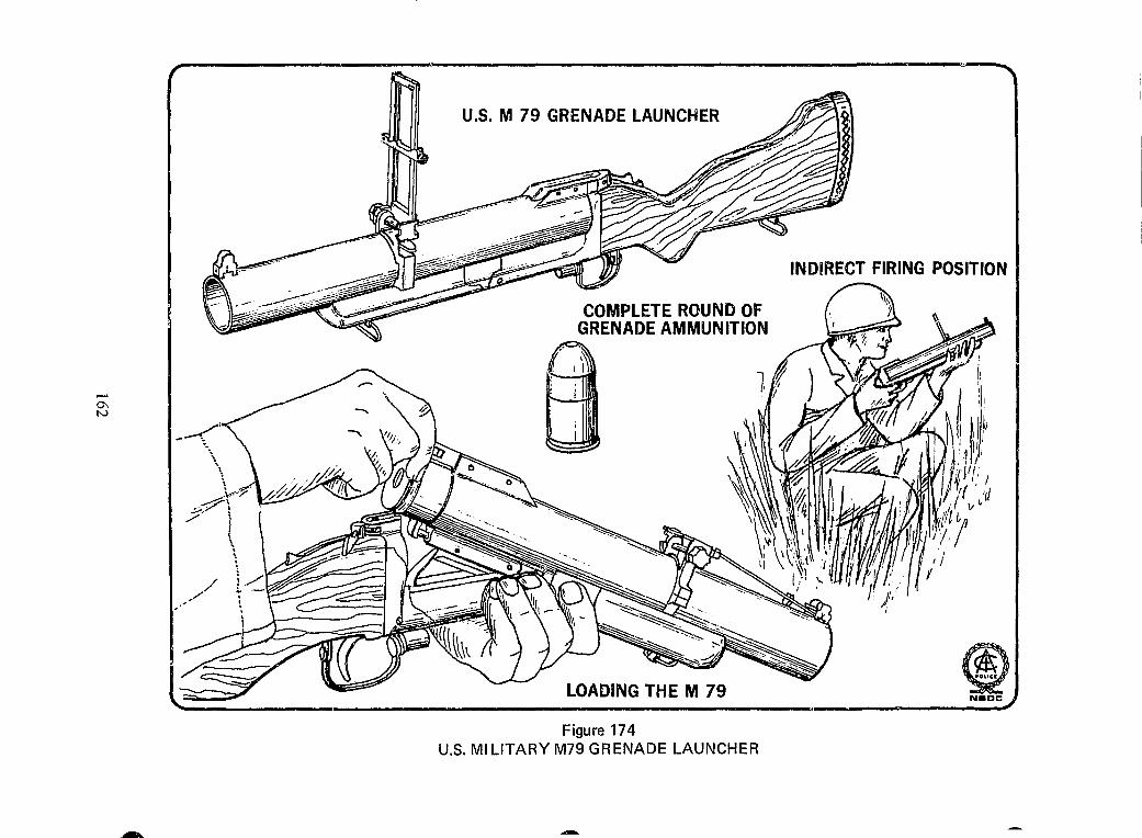
-0\ N
COMPLETE ROUND OF GRENADE AMMUNITION
I \~
LOADING THE M 79
Figure 174 U.S. MILITARY M79 GRENADE LAUNCHER
INDIRECT FIRING POSITION
® N.CC
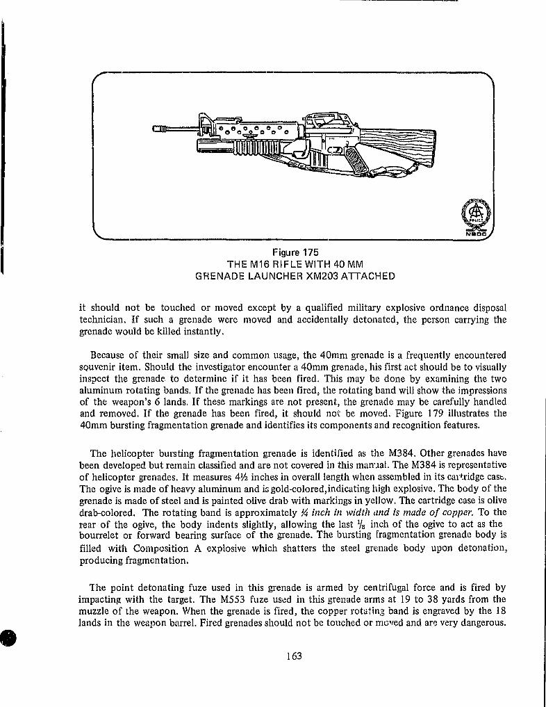
Figure 175 THE M16 RIFLE WITH 40 MM
GRENADE LAUNCHEH XM203 ATTACHED
it should not be touched or moved except by a qualified military explosive ordnance disposal technician. If such a grenade were moved and accidentally detonated, the person carrying the grenade would be killed instantly.
Because of their small size and common usage, the 40mm grenade is a frequently encountered sQuvenir it.em. Should the investigator encounter a 40mm grenade, his first act should be to visually inspect the grenade to determine if it has been fired. This may be done by examining the two aluminum rotating bands. If the grenade has been fired, the rotating band will show the impressions of the weapon's 6 lands. If these markings are not present, the grenade may be carefully handled and removed. If the grenade has been fired, it should not be mov{!d. Figure 179 illustrates the 40mm bursting fragmentation grenade and identifies its components and recognition features.
The helicopter bursting fragmentation grenade is identil1ed as the M384. Other grenades have been developed but remain classified and are not covered in this man'Jal. The M384 is representative of helicopter grenades. It measures 4V2 inches in overall length when assembled in its ca1'~ridge case, The ogive is made of heavy aluminum and is gold-colored,indicating high explosive. The body of the grenade is made of steel and is painted olive drab with markings in yellow. The cartridge case is olive drab-colored. The rotating band is approximately ~ inch in width and is made of copper. To the rear of the ogive, the body indents slightly, allowing the last l/S inch of the ogive to act as the bourrelet or forward bearing surface of the grenade. The bursting fragmentation grenade body is filled with Composition A explosive which shatters the steel grEil1ade body upon detonation, producing fragmentation.
The point detonating fuze used in this grenade is armed by centrifugal force and is fired by impacting with the target. The M553 fuze USed in this grenade arms at 19 to 38 yards from the muzzle of the weapon. When the grenade is fired, the copper rotaHn;g band is engraved by the 18 lands in the weapon b"rrel. Fired grenades should not be touched or moved and arp. very dangerous.
163

(
O~
COMPLETE ROUNDS OF LINKED GRENADE AMMUNITION
Figure 176 MK20, 40 MM MACHINE GUN
® NaDel

1 j W l .~
I
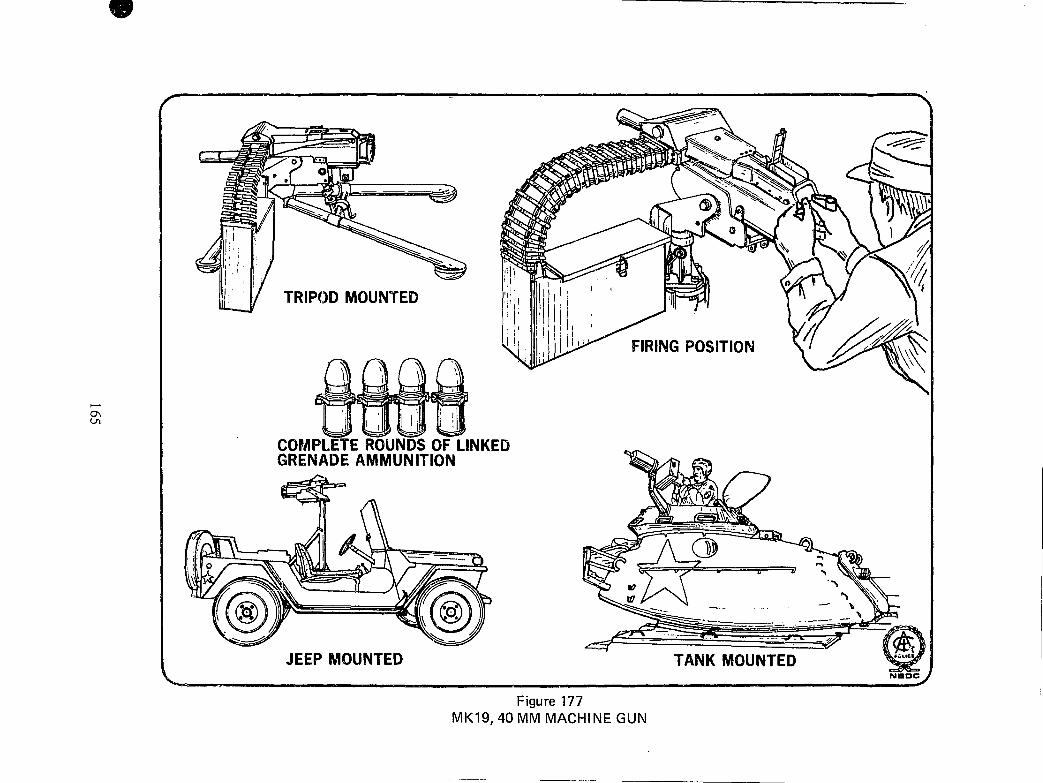
TRIPOD MOUNTED
I ;1 I !l
COMPLETE ROUNDS OF LINKED GRENADE AMMUNITION
JEEP MOUNTED
FIRING POSITION
~-------- .'
TANK MOUNTED
Figure 177 MK19, 40 MM MACHINE GUN
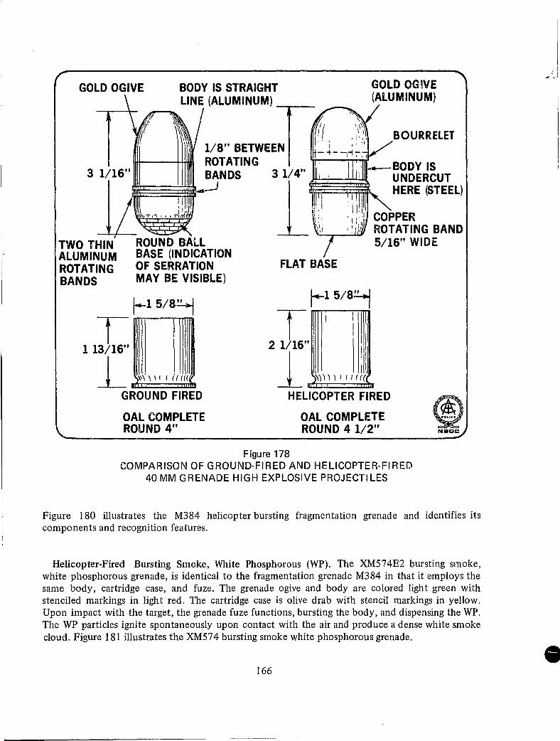
GOLD OGIVE BODY IS STRAIGHT GOLD OG~VE (ALUMINUM) LINE (ALUMINUM) --.-_
-.~. / \~ BOURRELET
Ii 1/8" BETWEEN ROTATING .-BODY IS
UNDERCUT 3 1/16" BANDS
TWO THIN ALUMINUM ROTATING BANDS
T 1 13/16"
~~~
ROUND BALL BASE (INDICATION OF SERRATION MAY BE VISIBLE)
1--15/8~
L "\ \" I iii" GROUND FIRED
OAL COMPLETE ROUND 4"
1:1,. ",HERE (STEEL)
, 1 !: II: COPPER , : ;1/' ROTATING BAND "'--r--"""""""-
5/16" WIDE
FLAT BASE
r-15/8~
T I 2 1/16" I
:11 1 ""I" /1((
HELICOPTER FIRED
Figure 178
OAL COMPLETE ROUND 4 1/2"
COMPARISON OF GROUND-FIRED AND HELICOPTER-FIRED 40 MM GRENADE HIGH EXPLOSIVE PROJECTILES
Figure 180 illustrates the M384 helicopter bursting fragmentation grenade and identifies its components and recognition features.
Helicopter-Fired Bursting Smoke, White Phosphorous (WP). The XM574E2 bursting smoke, white phosphorous grenade, is identical to the fragmentation grenade M384 in that it employs the same body, cartridge case, and fuze. The grenade ogive and body are colored light green with stenciled markings in light red. The cartridge case is olive drab with stencil markings in yellow. Upon impact with the target, the grenade fuze functions, bursting the body, and dispensing the WP. The WP particles ignite spontaneously upon contact with the air and produce a dense white smoke cloud. Figure 181 illustrates the XM574 bursting smoke white phosphorous grenade.
166

4'1
GOLD COLORED OGIVE (ALUMINUM)
MARKINGS IN YELLOW PAINT
OUVE DRAB COLORED
~~~~I:=-- BODY (ALUMINUM)
If;Df>~ :;IHOlili I I
II: iii n' \) \ , \ I I 1111
COMPLETE ROUND
ROTATING BANDS (ALUMINUM)
CARTRIDGE CASE OLIVE DRAB COLORED (ALUMINUM)
fUZE ROTATING 4rlli=1~~~ BANDS-~4---..::::r .
FRAGMENTATION BALL
FUZE BOOST \n·'·I:lI"~~ITION B
EXPLOSIVE
PROJECTILE
Figure 179
~-11Tf\-DETAIL OF THE ROTATING BAND OF A FIRED GRENADE. M 79 LAUNCHER HAS 6 LANDS IN BARREL
40 MM FRAGMENTATION GRENADE (M79 LAUNCHER)
Ground-Fired, Burning Tear Gas (CS) Grenade. The ground-fired 40mm grenade system is capable of delivering a tear gas grenade to distances of 437 yards. This tear gas grenade is designed as a combat weapon and is not intended for use in riot control. The XM651 EI tear gas (CS) grenade is employed to flush the enemy from reinforced positions or bunkers and has proven to be an effective combat grenade. It measures 4Y2 inches in length when assembled in its cartridge case, and has a flat-nosed heavy aluminum body with two aluminum rotating bands 3/1 6 inch apart. The base of the grenade has a 3/8 -inch vent hole closed by a plastic plug. The grenade body and ogive are painted or chemically colored grey. There is a ~-inch-wide red band around the body above the rotating bands and markings are stenciled in red paint. The single red band indicates a nonpersistant irritating chemical agent (CS).
The point detonating fuze, the XM581El is one of the more sensitive 40mm grenade fuzes in use and, after arming at approximately 30 yards, will function even if the grenade strikes a light twig or
167

GOLD COLORED OGIVE (ALUMINUM)
BOU RRElET~\t:--__ ~~~_
OLIVE DRAB BODY (STEEL)
MARKINGS IN YELLOW PAINT
CARTRIDGE CASE OLIVE DRAB (STEEL)
, ! I
, I
,I
FLAT STEEL BASE
BODY STEPS IN HERE
COPPER ROTATING BAND
NOTE ENGRAVING ON BOURRELET AND ROTATING BANi) OF FIRED GRENADE
STEEL BODY
OGIVE
l~~-FUZE
COMPOSITION ® l, _____________________ CR_g_~_~_~_~_G_B~A_N_D ____ EX_P_~_~_~_'V_E ____ ~_.: __ :
Figure 180 40 MM FRAGMENTATION GRENADE (HELICOPTER)
thick blade of grass. Functioning of the fuze causes the ignition train in the grenade to function and the burning CS-pyrotechnic material generates gas pressure which blows out the plastic plug in the base of the grenade and releases the CS. The CS-pyrotechnic mixture burns for about 25 seconds, creating a hissing sound and a dense white cloud.
To assist in rapid identification of the tear gas grenade under limited light conditions, the nose of the grenade is manufactured with a large flat surface and the cartridge case rim is notched in six places. Figure 182 illustrates the XM651 E 1 tear gas (CS) grenade and identifies its component parts and recognition features.
Ground-Fired, Ejection Signaling and Illumination Grenades. The 40mm ground-fired grenade launcher employs two ejection grenades with pyrotechnic fillers. These ejection grenades, which are
168

LIGHT GREEN
MARKINGS 40 MM STENCILED - .... SMOI(E (WP) IN LIGHT RED GTGXM!i741:!
COPPER ROTATING BAND
\ -4 \ I '-______ ...J
Figure 181 40 MM BURSTING SMOKE (WP) GRENADE (HELICOPTER)
used for signaling and to provide battlefield illumination, are identified as the XM585 white star cluster (signaling) and the XM583 illumination, white star, parachute grenades. Both grenades measure approximately 5~ inches in length when assembled in their cartridge cases. The cartridge case is shorter than normal, measuring only 13
/ 1 6 inches in length, and is olive drab-colored. The body of both grenades is constructed of phenolic plastic and is painted white. The rotating band is made of phenolic plastic which is brown in color. Markings on the side of the grenade body are stenciled in black paint and markings on the cartridge case are stenciled in yellow paint. The dome-shaped ogive of both grenades is made of plastic. The white plastic ogive snaps into place on the body and is popped off when the ejection charge fires.
The ogive also serves as an aid in selecting the desired grenade under limited light conditions through the use of a raised design. The ogive of the XM585 white star cluster has a raised letter "W" and 5 raised dots surrounding it to indicate that it is white in color and contains 5 stars. The XM583 white star illuminating parachute grenade has only the raised letter "W" on the ogive. The absence of the dots indicates that it is a parachute illumination flare grenade. Limited numbers of red and green star clusters have been produced and are marked with the raised letters "R" and "G" surrounded by 5 raised dots.
These ejection grenades do not have a fuze as such, but instead employ a simple pyrotechnic delay.
169

FLAT NOSE
/,~s 40 ~'~ ',,-13 XMGS' II
MARKINGS STENCILED IN RED PAINT
{. 1 ' I ,/-
~" WIDE I~~--REDBAND----oo
~ALUMINUM ROTATING BANDS 3/16" APART
Figure 182
PLASTIC PLUG IN VENT HOLE
I ,
40 MM 8URNING TEAR GAS (CS) GRENADE (M79 LAUNCHER)
® NBDC
When the grenade is fired, the propellant gases launch the projectile and, at the same time, the flame from the burning pr0pellant ignites a 5~second pyrotechnic delay located in the base of the grenade. When the grenade, which has been fired upwards, reaches or nears the zenith of its trajectory, the 5-second pyrotechnk delay burns into a black powder ejection charge which is inside the base of the grenade. The buming black powder ejection charge ignites and ejects the stars or parachute flare. Figure 183 illustrates these ejection grenades and identifies, their component parts and recognition features.
Ground-Fired (,oim-ed Smoke Signaling Grenades. A series of colored smoke signaling grenades has been developed for use with the 40mm grenade launcher. These grenades are identical in appearance, size, and function to the white star cluster and illuminating parachute flare. They differ only in that they contain a colored smoke canister in place of the stars or flare. Externally they may
170

5 SECOND DELAY PYROTECHNIC
BLACK POWDER EJECTION CHARGE
t-------- 4.3 IN. -------4----.-l
5 SECOND DELAY PYROTECHNIC
BLACK POWDER EJECTION CHARGE
...... ------ 4.3 It~.-------~
Figure 183
OGIVE
40 MM EJECTION GRENADE (SIGNALING AND ILLUMINATION) M79 LAUNCHER
171
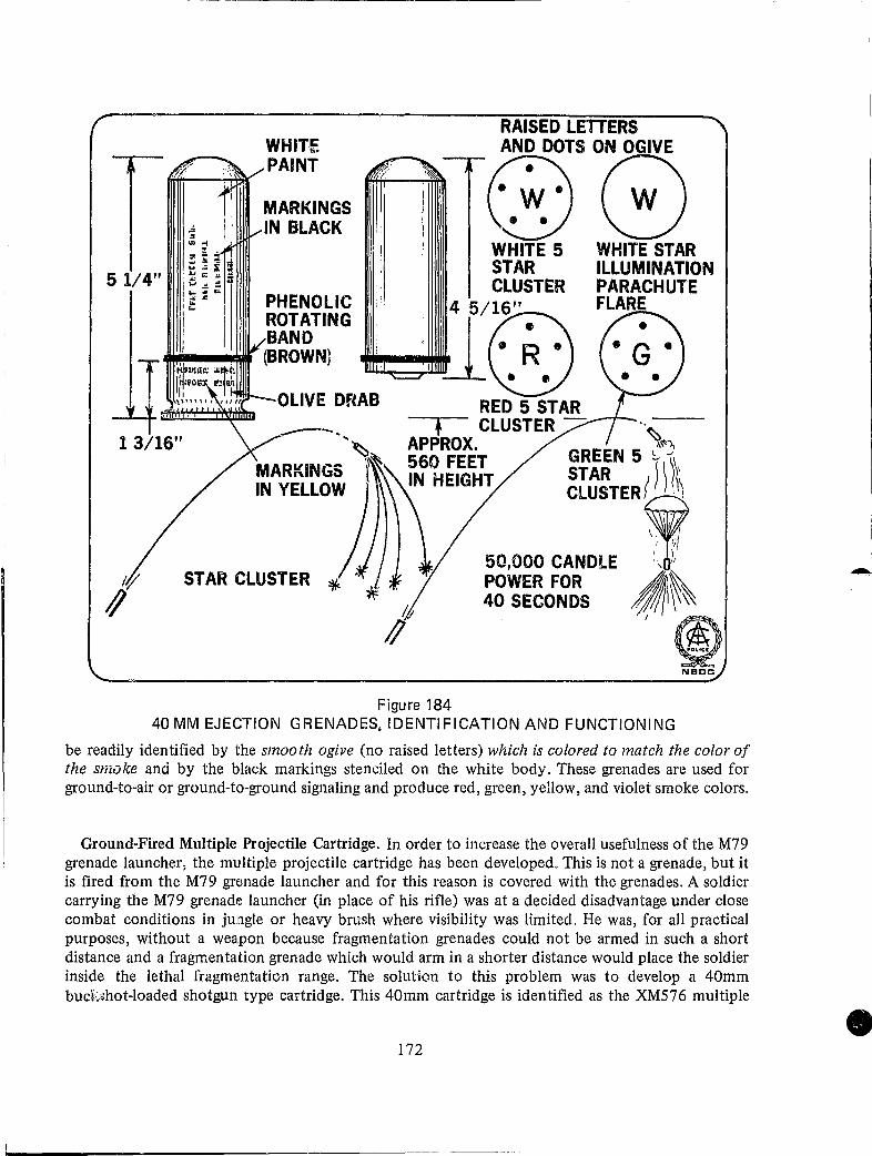
5 1/4" '" .. i. ,.J.j
" .., :IJ .. l~ ... ',. I ....
Ii
WHITE PAINT
MARKINGS IN BLACK
, ! !
RAISED LETTERS mS0G) WHITE 5 WHITE STAR STAR ILLUMINATION CLUSTER PARACHUTE
:~!i~,~g .,.-41 4 r~."~) FLARE __ ~I" (BROWN} ~ .., Ii
- .. ~ MARKINGS '~ IN YELLOW
STAR CLUSTER *
RED 5 STAR + CLUSTER - __ --r- .. ~
APPROX. ~"'"), 560 FEET GREEN 5 s -'I~ , STAR Il \ IN HEIGHT CLUSTERf II, \
50,000 CANDLE ,
:~~~~~S ~I~~ ®
NODe
Figure 184 40 MM EJECTION GRENADES, IDENTIFICATION AND FUNCTIONING
be readily identified by the smooth ogive (no raised letters) which is colored to match the color of the smoke and by the black markings stenciled on the white body. These grenades are used for ground-to-air or ground-to-ground signaling and produce red, green, yellow, and violet smoke colors.
Ground-Fired Multiple Projectile Cartridge. In order to increase the overall usefulness of the M79 grenade launcher, the multiple projectile cartridge has been developed. This is not a grenade, but it is fired from the M79 grenade launcher and for this reason is covered with the grenades. A soldier carrying the M79 grenade launcher (in place of his rifle) was at a decided disadvantage under close combat conditions in jungle or heavy brush where visibility was limited. He was, for all practical purposes, without a weapon because fragmentation grenades could not be armed in such a short distance and a fragmentaltion grenade which would arm in a shorter distance would place the soldier inside the lethal fragmentation range. The solution to this problem was to develop a 40mm buck.~hot-Ioaded shotgun type cartridge. This 40mm cartridge is identified as the XM576 multiple
172

projectile, anti-personnel round. The cartridge case is aluminum and is olive drab. The projectile, more correctly identified as a sabot, is black (early models were clear) polyethylene plastic with no fuze or ogive. Located in a clear plastic cup in the center of the sabot are 20 lead pellets (Number 2 buckshot), covered by a black plastic snap-on cap. When the cartridge is loaded into the M79 grenade launcher and fired, the force of setback causes the plastic cup holding the lead pellets to move slightly rearward and unsnap the covering cap.
When the projectile (sabot) leaves the muzzle of the weapon, it is rapidly slowed by air resistance, and the 20 lead pellets push the cap aside and spread out in a classic shotgun pattern. Because of the light weight of the projectile, the muzzle velocity rises to 800 fps, creating a very effective anti-personnel weapon. Figure 185 illustrates the XM576 multiple projectile anti-personnel cartridge and its functioning.
BLACK PLASTIC
CLEAR PLASTIC CUP
OBTURATOR
SABOT / 20 PELLETS NUMBER 2 BUCKSHOT
PACKED IN PULVERIZED STYROFOAM
-::0. T. _ ~J ~~{_ -_.-<.. -.---- .. ; 0
0
·0
==-==s- . • .-- _, j.r\. - . • 00 • : •
~ \~J' 00 . 0
AIR RESISTANCE ON SABOT
Figure 185
® NBec:
40 MM MULTIPLE PROJECTILE CARTRIDGE (M79 LAUNCHER)
173
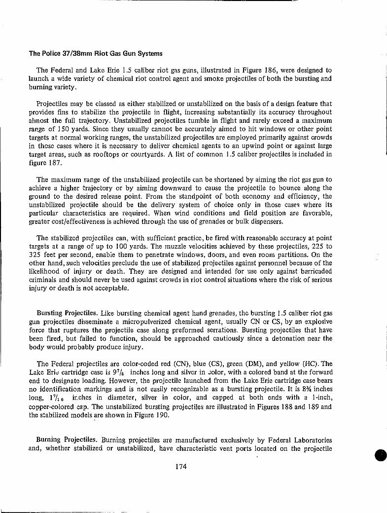
----------------------------_______________ w~----
The Police 37/38mm Riot Gas Gun Systems
The Federal and Lake Erie 1.5 caliber riot gas guns, illustrated in Figure 186, were designed to launch a wide variety of chemical riot control agent and smoke projectiles of both the bursting and burning variety.
Projectiles may be classed as either stabilized or un stabilized on the basis of a design feature that provides fins to stabilize the projectile in flight, increasing substantially its accuracy throughout almost the full trajectory. Unstabilized projectiles tumble in flight and rarely exceed a maximum range of 150 yards. Since they usually cannot be accurately aimed to hit windows or other point targets at normal working ranges, the unstabilized projectiles are employed primarily against crowds in those cases where it is necessary to deliver chemical agents to an upwind point or against large target areas, such as rooftops or courtyards. A list of common 1.5 caliber projectiles is included in figure 187.
The maximum !range of the un stabilized projectile can be shortened by aiming the riot gas gun to achieve a higher Itrajectory or by aiming downward to cause the projectile to bounce along the ground to the deJsired release point. From the standpoint of both economy and efficiency, the unstabilized projectile should be the delivery system of choice only in those cas~s where its particular charac;teristics are required. When wind conditions and field position are fa.vorable, greater cost/effectiveness is achieved through the use of grenades or bulk dispensers.
The stabilized projectiles can, with sufficient practice, be fired with reawnable accuracy at point targets at a range of up to 100 yards. The muzzle velocities achieved by these projectiles, 225 to 325 feet per second, enable them to penetrate windows, doors, and even room partitions. On the other hand, such velocities preclude the use of stabilized projectiles against personnel because of the likelihood of injury or desth. They are designed and intended for use only against barricaded criminals and should never be used against crowds in riot control situations where the risk of serious injury or death is not acceptable.
Bursting Projectiles. Like bursting chemical agent hand grenades, the bursting 1.5 caliber riot gas gun projectiles disseminate a micro pulverized chemical agent, usually CN or CS, by an explosive force that ruptures the projectile case along preformed serrations. Bursting projectiles that have been fired, but failed to function, should be approached cautiously since a detonation near the body would probably produce injury.
The Federal projectiles are color-coded red (eN), blue (CS), green (DM), and yellow (He). The Lake Eri..: cartridge case is 97/ S inches long and silver in ~olor, with a colored band at the forward end to designate loading. However, the projectile launched from the Lake Erie cartridge case bears no identification markings and is not easily recognizable as a bursting projectile. It is 8% inches long, PIt 6 inches in diameter, silver in color, and capped at both ends with a I-inch, copper-colored ca.p. The unstabilized bursting projectiles are illustrated in Figures 188 and 189 and the stabilized models are shown in Figure 190.
Burning Projectiles. Burning projectiles are manufactured exclusively by Federal Laboratories and, whether stabilized or unstabilized, have characteristic vent ports located on the projectile
174

__ " --------~-------------------------
STOCK BOLT
LEAF SIGHT ASSEMBLY
50 YARD SIGHT K FRO'NT
LOCK PIN SIG LOCK SPRING
~~..J~~-HINGE PIN
BARREL EXTRACTOR
SEAR SPRING TRIGGER ASSEMBLY
RACTOR PINS
FIRING PIN SLEEVE FIRING PIN SPRING
HAMMER
HAMMER ---=:-. PIN
REAR SIGHT ASSEMBLY
FRONT SIGH
BARREL
.... -r~nEL SPRING
EJECTOR & SPRING
LOCKING BOLT
LOCKING BOLT SPRING & PIN
HAMMER SPRING
RECOIL PAD & SCREWS
GER SPRING & SCREW ®
Nacc
Figure 186 POLICE RIOT GAS GUNS 37/38 MM SYSTEMS
175
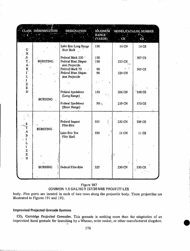
'" ' ' '.--~-- I ~. 1- '. ,If.' ,I,
---.o.~ , ....... . . , . ' . -: CLASS DlSSEMINA'f ON DESIGNATION MAXIMUM: 'MODEL/CATALOG NUMBER '
., II • ..,.,.., ~. --- - " '" ":",' RANGE' ". w' ~. " .", I .'. ./ '. 'I - • (YARD~l) _ ~ eN .' es . . . I) • ~.\ '.. • ."
,.
"
\.
..
U N
.. ,S Tc A" B I" L I Z E ·D
Ci'~S -T A B
., I L I Z E D
Figure 187 COMMION 1.5 CALIBER (37/38 MM) PROJECTI LES
body. Five ports are located in each of two rows along the projectile body. These projectiles are illustrated in Figures 191 and 192.
Improvised Projected Grenade Systems
CO2 Cartridge Projected Grenades. This grenade is nothing more than the adaptation of an improvised hand grenade for launching by a Whamo, wrist rocket, or other manufactured slingshot.
176
L. _____ _
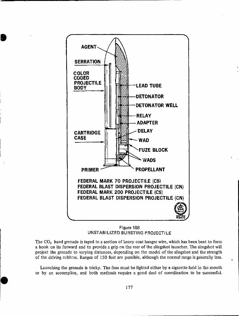
AGENT
SERRP:nON
COLOR CODED PROJECTU.,E BODY
CARTRIDGE CASE
-LEAD TUBE
I~~-DETONATOR
~tl--DETONATOR WELL
I~~-RELAY
L.J_~t-- ADAPTER
fUZE BLOCK
I~VADS
PROPELLANT
FEDERAL MARK 70 PROJECTILE (CS) FEDERAL BLAST DISPERSION PROJECTILE (CN) FEDERAL MARr( 200 PROJECTILE (CS) FEDERAL BLAST DISPERSION PROJECTILE (eN)
Figure 188 UNSTABILIZED BURSTING PROJECTILE
® NIIDC
The CO2 hand grenade is taped to a section of heavy coat hanger wire, which has been bent to form a hook on its forward end to provide a grip (In the rear of the slingshot launcher. The slingshot will project the grenade to varying distances, depending on the model of the slingshot and the strength of the driving rubbr'rs. Ranges of 150 feet are possible, although the normal range is generally less.
Launching the grenade is tricky. The fuse must be lighted either by a cigarette held in the mouth or by an accomplice, and both methods require a good deal of coordination to be successful.
177

LAKE ERiE LONG RANGE INSTANTANEOUS DISCHARGE PROJECTILE
REAR COPPER BURSTING END CUP CHARGE
REAR PRESSURE
FLASH SEAL
BURSTING CHARGE PRESSURE
AD
SILVER PROJECTILE BODY
COPPER END CAP
WAD I'_~~~~~~~~~~~~-WAD
PRIMER-'-
DELAY FUZE
POWDER RETAI~IER WAD COLOR CODE BAND
~----8 3/4"-----.1-,
PROJECTILE
LONG RANGE' RIOT SHE:LL ..t'\"- 'l(-""' .... ~ <!-"'"'
- .~-- .. -~:-:.~ ... ~t-\V ... '. '''"~ :~~\.\._.
14-------"1 7/8"----
CARTRIDGE
Figure 189 UNSTABILIZED BURSTING PROJECTILES
LACQUER SEAL
® Nacc
Frequently, the grenade will strike the slingshot when launched and land nearby instead of in the intended target area. The coat hanger hook is sometimes accidentally straightened, and the person launching the grenade must rapidly dispose of it if the fuse is burning. This type of projected grenade is not very popular. Figure 193 illu:.trates the slingshot-launched grenade.
Explosive Arrow Grenades. A slightly different approach to projected grenades is used in explosive arrow grenades. The first grenade of this type was recovered in Illinois and consisted of a
178
-------------------~.' "",'".-. ----FEDERAL IMPACT FLlTE·RITE PROJECTILE
STABILIZER ..... :: .. :.:::. WEIGHT .:.::.:.: .. : ..
------ -----.
DETONATOR WELL
PRIMER
FIRING PIN FIN
:: trr ~ PROJECTILE BODY PROPELLENT CHARGE .. ~~}\{.~ COLOR CODED BODY
:»~{J GROOVE TO FACILITATE PROJECTILE 1[ .. ···::··:· .. RUPTURE OF PROJECTILE BASE :1 I'
Ii I' i LAKE ERIE TRU.FLlTE BARRICADE PR~I~~:~LE Ii SILVER BURSTER
WEIGHT TUBE
I ; CARTRiDGE TAil
; II CASE FIN FIN VANE ~E=--=:.:: I] ~ HINGE PIN FIN SPRING
INERTlj\
PROPELLING CHARGE
TAIL FIN STUD FUZE AND BUSTER TUBE ADAPTER
PRIMER SEAT
® N.CC
Figure 190 STABI LlZED BURSTING PROJECTI LES
179
I

PROPELLENT CHARGE
PRIMER
DELAY
PROJECTILE BASE SILVER PROJECTILE BODY COLOR CODED
1<II-__________ 8Y2" -------------Il0l
FEDERAL SPEDEHEAT PROJECTILE (LONG AND SHORT RANGE)
Figure 191 Ul\!STABILlZED BURNING PROJECTILES
36-inch hollow aluminum shaft arrow which had been filled with plastic explosive. A nonelectric blasting cap with a 12-gauge shotgun primer inserted into th~: open end of the cap was used to detonate the explosive. The blasting cap and shotgun primer were held in position at the forward end of the arrow by the packed explosive. A- striker was positioned in front of the primer and held there by a light shear wire passing through the arrow shaft and the striker. When the arrow was launched, impact with a hard target would cause the striker to break the shear wire and fire the shotgun primer. The flash from the primer caused the detonation of the blasting cap and the explosive filler. The aluminum arrow shaft produces rather poor fragmentation, but the arrow grenade does produce an excellent detonation when loaded with plastic explosive.
The second type of arrow grenade was recovered from the National Minutemen Organization in New Mexico. along with quantities of explosives and other devices. Once again, the hollow aluminum shaft arrow was used, but attached to the front of the arrow shaft with epoxy cement was a %-inch section of thin-walled aluminum tubing approximately 6 inches in length. The tubing was filled with commercial explosive. The forward end of the hollow arrow shaft contained a nonelectric blasting cap with a shotg'Jn primer inserted into the open end of the cap, with the primer facing rearward. A 20-penny nail with the head removed was inside the hollow shaft with the pointed end of the nail aimed at the primer. A hole drilled through the arrow shaft allowed for the
180

....... 00 .......
COMPRESSED AGENT MIXTURE
PROJECT BODY COLOR CODED
)
~
FUZE BLOCK
DELAY
PROJECTILE BASE SILVER
FEDERAL FLITE·RITE PROJECTILE~
Figure 192 STABI LlZED BURNING PROJECTI LES
ID
PROPELLENT CHARGE
COMPRESSED FIN ASSEMBLY
® '\IBCe
WRIST ROCKET SLINGSHOT
C02 CARTRIDGE GRENADE
COAT HANGER
Figure 193 SLINGSHOT LAUNCHED GRENADE
FUSE
® NIllDC
insertion of a safety pin to prevent accidental firing during handling. Just prior to launching, the safety pin was removed. Upon impact with the target, the nail moved forward due to inertia and struck the primer, firing it. The flash from the primer detonated the nonelectric blasting cap and the explosive charge. No tests have been conducted with this grenade but unless very carefully assembled, it could be hazardous and unreliable to employ. Figure 194 illustrates the explosive arrow grenades.
Explosive-Filled Pistol-Launcbed Grenades. The Minutemen also developed a grenade which they identify as an explosive, pistol-Ia.unched grenade. The construction of the grenade is identical to the arrow grenade except for the addition of 4 aluminum fins and a solid aluminum rod at the rear of the grenade. Apparently, the grenade was intended to be launched from a .32 or .38 caliber pistol by firing a blank cartridge. Because of the weight of the grenade, it is estimated that firing the pistol could cause injury to the person firing it. Additionally, unless the grenade were securely assembled in manufacture, the setback forces produced at the firing of the blank cartridge could detonate the grenade by moving the blasting cap and primer assembly rearward onto the striker, Figure 195 illustrates the explosive-filled pistol-launched grenade.
Shotgun-Launched Firebomb. Several underground publications have provided plans for the construction of a shotgun-launched firebomb employing a self-igniting chemical impact fuze system (sugar/chlorate and sulfuric a.cid/gasoline). The firebomb is placed inside a tin elm which is securely attached to a wooden rod and fits down the barrel of a 12-gauge shotgun. A standard shotgun shell, with the shot removed, is uSt:d to drive the grenade to the target. The system is capable of launching the firebomb approximately 240 feet under normal conditions. The shotgun-launched firebomb has not been used to any great extent, probably because the bottle frequently is broken by the force of the launch and bathes the firing position in burning gasoline. This device is illustrated in Figure 196.
182

sr ~UN PRIMER
~ NON·ELECTRIC U\ BLASTING CAP SHEAR WIRE
HOLLOW ALUMINUM SHAFT ARROW FILLED WITH EXPLOSIVE
b---SAFETV PIN ALUMINUM TUBING FILLED WITH EXPLOSIVE NAIL STRIKER
NON·ELECTRIC BLASTING CAP
SHOTGUN PRIMER
Figure 194 EXPLOSIVE ARROW GRENADES
® N&CC

_____________________ '1"
ALUMINUM TUBING BODY HOLLOW FILLED WITH EXPLOSIVE ALUMINUM
TUBE
EPOXY ~ ,/ CEMENT SAFETY PIN
NON·ELECTRIC BLASTING CAP
SHOTGUN PRIMER
•
LARGE NAIL AS STRIKER
Figure 195
SOLID ..----, ALUMINUM ROD
ALUMINUM FINS
® Noce
EXPLOSIVE-FI LLED PISTOL-LAUNCHED GRENADE
WOODEN ROD
WOODEN BLOCK
TIN CAN
Figure 196 SHOTGUN-LAUNCHED FI RE BOMB
184
SELF IGNITING BEER BOTTLE FIREBOMB
® Nace

I I
I