www. JoSSonline.com Design …
22
www.adeepakpublishing.com www. JoSSonline.com Jovanovic, N. et al. (2019): JoSS, Vol. 8, No. 2, pp. 859–880 (Peer-reviewed article available at www.jossonline.com) Copyright © A. Deepak Publishing. All rights reserved. JoSS, Vol. 8, No. 2, p. 859 Design and Testing of a Low-Cost, Open Source, 3-D Printed Air-Bearing-Based Attitude Simulator for CubeSat Satellites Nemanja Jovanovic Aalto University Finland Joshua M. Pearce Aalto University, Finland Michigan Technological University Houghton, Michigan US Jaan Praks Aalto University Finland Abstract With the surge of interest in nano-satellites, there is a concomitant need for high quality, yet affordable sim- ulation and testing environments. It is particularly challenging to experimentally evaluate nano-satellite attitude control systems in a test environment. This article investigates the technical feasibility of fabricating a low-cost air-bearing platform with three degrees of freedom of angular motion using desktop 3-D printing technology with limited printing resolution. An open source air-bearing attitude simulator for complete 1U CubeSat is pro- posed, manufactured, and characterized. The platform is equipped with directional air nozzles that enable exter- nal torque generation in order to cancel out i) parasitic moments of inertia from the satellite’s enclosure and ii) error torque produced by imperfections. It is also capable of simulating disturbances in a space environment. The results show that the torques produced by the nozzles can reach beyond 0.001 Nm and are sufficient to re- move error torques and provide torque compensation of the orders of 0.0004 Nm. Removing the effects of grav- ity torque with the nozzles proved to be unachievable with the current design, requiring precise positioning of the CubeSat within the enclosure. Future work has been identified for a number of improvements to the design and details for the further development of the platform. Introduction Satellites are generally out of reach of any un- foreseen maintenance procedure after deployment in orbit. Thus, to ensure the success of a mission, engi- neers invest significant effort in satellite testing to ensure mission reliability. Tests like thermal-vacuum cycling (Parker, 1984) and mechanical quasi-static loads (ECSS-E-HB-32-26A, 2013) aid in simulating circumstances that a satellite can encounter. Replicat- ing the space environment in a laboratory is Corresponding Author: Nemanja Jovanovic – [email protected] Publication History: Submitted – 03/07/19; Revision Accepted – 09/06/19; Published – 10/10/19
Transcript of www. JoSSonline.com Design …

www.adeepakpublishing.com www. JoSSonline.com
Jovanovic, N. et al. (2019): JoSS, Vol. 8, No. 2, pp. 859–880
(Peer-reviewed article available at www.jossonline.com)
Copyright © A. Deepak Publishing. All rights reserved. JoSS, Vol. 8, No. 2, p. 859
Design and Testing of a Low-Cost, Open Source, 3-D Printed Air-Bearing-Based
Attitude Simulator for CubeSat Satellites Nemanja Jovanovic
Aalto University
Finland
Joshua M. Pearce Aalto University, Finland
Michigan Technological University
Houghton, Michigan US
Jaan Praks Aalto University
Finland
Abstract
With the surge of interest in nano-satellites, there is a concomitant need for high quality, yet affordable sim-
ulation and testing environments. It is particularly challenging to experimentally evaluate nano-satellite attitude
control systems in a test environment. This article investigates the technical feasibility of fabricating a low-cost
air-bearing platform with three degrees of freedom of angular motion using desktop 3-D printing technology
with limited printing resolution. An open source air-bearing attitude simulator for complete 1U CubeSat is pro-
posed, manufactured, and characterized. The platform is equipped with directional air nozzles that enable exter-
nal torque generation in order to cancel out i) parasitic moments of inertia from the satellite’s enclosure and ii)
error torque produced by imperfections. It is also capable of simulating disturbances in a space environment.
The results show that the torques produced by the nozzles can reach beyond 0.001 Nm and are sufficient to re-
move error torques and provide torque compensation of the orders of 0.0004 Nm. Removing the effects of grav-
ity torque with the nozzles proved to be unachievable with the current design, requiring precise positioning of
the CubeSat within the enclosure. Future work has been identified for a number of improvements to the design
and details for the further development of the platform.
Introduction
Satellites are generally out of reach of any un-
foreseen maintenance procedure after deployment in
orbit. Thus, to ensure the success of a mission, engi-
neers invest significant effort in satellite testing to
ensure mission reliability. Tests like thermal-vacuum
cycling (Parker, 1984) and mechanical quasi-static
loads (ECSS-E-HB-32-26A, 2013) aid in simulating
circumstances that a satellite can encounter. Replicat-
ing the space environment in a laboratory is
Corresponding Author: Nemanja Jovanovic – [email protected]
Publication History: Submitted – 03/07/19; Revision Accepted – 09/06/19; Published – 10/10/19

Jovanovic, N. et al.
Copyright © A. Deepak Publishing. All rights reserved. JoSS, Vol. 8, No. 2, p. 860
nontrivial, and because of that, satellite systems veri-
fication methods suffer many restrictions, including
imperfect vacuum conditions (Guthrie, 1963) and dif-
ferences in ambient magnetic fields.
Rotational motion of a satellite is produced by an
attitude control system in interaction with the envi-
ronment (Fortescue et al., 2011). Surroundings are
crucial for satellite attitude control, regardless if in-
ternal or external angular momentum is exchanged.
Environmental effects that influence the satellites'
angular velocities in orbit include gravity gradient,
atmospheric drag, solar pressure, and the absence of
friction (Fortescue et al., 2011). In a laboratory, a
nearly frictionless environment can be achieved using
air-bearing simulator platforms (Smith, G. Allan,
1964). There are several examples of air-bearing plat-
forms for larger satellites (mini-satellites and heavier
categories) that can handle substantial loads
(Boynton, 1996; Kim et al., 2001; Peck et al., 2003).
Because of structural restrictions, most of those air-
bearing platforms can support only a subset of a sat-
ellite system.
Cost-effective launch opportunities, commercial-
off-the-shelf (COTS) component availability, and
scientific payload miniaturization created the recent
surge in interest (Doncaster et al., 2017) in the use of
nano-satellites (or nanosats, artificial satellites having
a wet mass between 1 and 10 kg). This is evident on
both individual as well as formation flying and con-
stellation missions or satellite swarms (Bouwmeester
and Guo, 2010; Bandyopadhyay et al., 2016;
Verhoeven et al., 2011). Nano-satellite and micro-
satellite segments of the satellite launch industry have
been growing rapidly in recent years (Palerm Serra et
al., 2014), the majority of which are built in universi-
ty and start-up laboratories with no access to large
funds. Early nano-satellites avoided the need to rely
on active attitude control systems due to the com-
plexities involved, although recent trends show sig-
nificant increases in the use of magnetic-torquer and
reaction-wheel based control systems (Xia et al.,
2017). To some extent, this places the maturity of the
attitude control technology behind other nano-
satellite subsystems, like communications and elec-
trical power modules.
Air-bearing simulators can alter physical proper-
ties relevant for attitude dynamics, like center of
mass. Unlike with the larger satellites, changes in
nano-satellites’ physical properties, introduced when
attached to the heavier air-bearing platforms used for
larger satellites, can easily dominate the overall sys-
tem dynamics. Disturbance torques have a larger
relative impact over smaller moments of inertia of
nano-satellites. Thus, affordable simulators with good
precision within a small torque range are needed for
nano-satellites, yet large satellite simulator platforms
are structurally limited and unable to provide rota-
tional, full, three-degrees-of-freedom (3DOF)
(Schwartz et al., 2003). To overcome these limita-
tions, several approaches are used for nano-satellite
attitude simulators, including platforms with auto-
matic center-of-gravity adjustments (Woo et al.,
2011; Kwan et al., 2015) for canceling disturbance
torque and lightweight structures (Gavrilovich et al.,
2014; Gavrilovich et al., 2016) for reducing parasitic
moments of inertia. A promising solution is the
placement of nano-satellites such as CubeSats
(Woellert et al., 2011) in a spherical enclosure
(Boynton, 1996; Ustrzycki et al., 2011; Schwartz and
Hall, 2004; Culton et al., 2017), allowing for unre-
stricted 3DOF angular motion. However, reducing
undesired effects for various types of nano-satellites
requires developing custom simulation platforms,
which can result in high costs for satellite testing.
The high costs of laboratory equipment-based testing,
in turn, can reduce testing effectiveness and accessi-
bility when funds are limited.
Previous work has established that open source
hardware solutions (Gibb, 2014; Pearce, 2012;
Pearce, 2013) using fused filament fabrication (FFF)-
based 3-D printing (Jones et al., 2011; Sells et al.,
2010; Bowyer 2014) could reduce research equip-
ment costs by one or two orders of magnitude (Fisher
and Gould, 2012; Pearce, 2014; Pearce, 2015)
through a wide array of applications (Pocero et al.,
2017; Jiang and Claudel, 2017; Dhankani and Pearce,
2017; Brower et al., 2017). Also, FFF 3-D printing
technology enhances agile and rapid prototyping
(Rayna and Striukova, 2016), which has been shown
useful in development of satellite systems (Karvinen,

Design and Testing of Low-Cost Open Source 3-D Printed Air-Bearing-Based Attitude Simulator for CubeSat Satellites
Copyright © A. Deepak Publishing. All rights reserved. JoSS, Vol. 8, No. 2, p. 861
2015). To exploit this practice and provide a low-cost
and effective solution for nano-satellite testing, an
open-source attitude simulation platform is proposed
that can be manufactured using widely accessible
FFF 3-D printing technology.
This study investigates the technical feasibility of
fabricating an air-bearing platform using FFF-based
3-D printing technology. Requirements of high preci-
sion and small tolerances are often given for air-
bearing platform designs (Boynton, 1996). These re-
quirements are challenged here, as common FFF-
based 3-D printers have limited printing resolutions
(generally 100 µm positional accuracy). An air-
bearing attitude simulator for CubeSats is proposed
that allows testing of complete nano-satellite systems,
including attitude sensor calibrations and full end to
end attitude control tests. To cancel out parasitic
moments of inertia from the satellite’s enclosure and
error torque produced by imperfections, the platform
is equipped with directional air nozzles that enable
external torque generation. In addition, using this de-
sign, nozzles can be used to simulate disturbances
from the space environment. The platform is de-
signed to provide unrestricted 3DOF using a spheri-
cal enclosure. The full CAD design of the FFF 3-D
printable attitude simulator for CubeSat satellites sys-
tem is disclosed here, using an open source license
and operational protocols. The CubeSat attitude
simulator is manufactured and characterized for error
torque and directional air nozzles performance. The
results are used to evaluate error torque and parasitic
moments of inertia cancellation prospects. Finally,
this approach is discussed, and conclusions are drawn
about the viability of distributed manufacturing atti-
tude simulators for CubeSat satellites.
Theory
The proposed open source air-bearing platform
consists of a rotor and stator. The rotor is a spherical
enclosure, which encompasses a CubeSat. The stator
is a stationary base with a spherical socket conformal
with the rotor. The socket contains a number of ori-
fices on the surface and optional grooves, which are
connected to a supply of pressurized air that lifts the
rotor. This forms a fluid film layer in the space be-
tween the rotor and stator, that acts as an effective
lubricant (Hamrock et al., 2004). Thus, fluid film lu-
brication theory is used to illustrate the interaction
between rotor and stator. Nearly frictionless rotation-
al motion is provided to the rotor by the thin air layer
so the same rotational kinematics and dynamics equa-
tions, which are also used to describe angular mo-
tions of satellites, can be applied in this case (Sidi,
1997). The directional air nozzles on the platform
exhaust pressurized air on the surface of the rotor at
an angle, applying a drag force (Fortescue et al.,
2011), which, in turn, generates torque.
2.1. Fluid Film Lubrication Dynamics
The schematic of the attitude simulator shown in
Figure 1 can be classified as a spherical aerostatic
bearing system. Because of the externally generated
pressure, the bearing is effective even during slow
angular velocities of the rotor (Hamrock et al., 2004).
Important properties of air-bearings to consider are
load capacity, fluid film thickness and friction and
error torques. These properties can be studied in de-
tail using the Reynolds equation, which is derived
from Navier-Stokes and Continuity equations in the
case of “slow viscous motion” flow (Hamrock et al.,
2004; Wilcock, 1965). Analytical solutions to the
properties are presented in (Wilcock, 1965; Tanaka et
al., 2011) and (Rakwal and Bamberg, 2005). Howev-
er, direct application of the equation to the case of 3-
D printed system might be unsatisfactory, as analyti-
cal solutions are derived for bearings with perfect
spherical surfaces. The FFF-based 3-D printed sur-
face has ridges in print direction the width of the z-
step height. Small flaws are known to generate nota-
ble error torques, as shown in (Wilcock, 1965). Fur-
thermore, theoretical and experimental results in
(Tanaka et al., 2011) differ even for a more conven-
tional fabrication technology. Thus, only qualitative
analysis of the properties will be used in determining
the simulator platform design. The potential of low-
cost and rapid iterative prototyping with 3-D printing
technology additionally supports the use of the quali-
tative analysis, where a satisfying solution can be
found with iterative design.

Jovanovic, N. et al.
Copyright © A. Deepak Publishing. All rights reserved. JoSS, Vol. 8, No. 2, p. 862
2.1.1. Load Capacity and Fluid Film Thickness
To lift the rotor, sufficient pressure is needed at
the socket orifices or inside the grooves. The pressure
generates the force that needs to exceed the force
from gravity on the rotor. Once the rotor is lifted, the
air is free to flow through the recess space, where the
pressure drops. The force, ��, that now supports the
load over the whole area of stator socket, is:
�� = ∫(𝑝𝜃 − 𝑝𝑎) 𝑐𝑜𝑠 𝜃𝑑𝜃�� = 2𝜋𝑅𝑟2 ∫ (𝑝𝜃 −
𝜃2
𝜃1
𝑝𝑎) 𝑐𝑜𝑠 𝜃 𝑠𝑖𝑛 𝜃𝑑𝜃�� (1)
where Rr is the rotors radius, θ is the angle from the
vertical axis, pa is ambient pressure, pθ is pressure in
the recess space, which depends on the angle θ (Wil-
cock, 1965), while �� is a vertical unit vector. If the
load mass increases, the pressure will increase too
and compensate the support force (Hamrock et al.,
2004). This behavior is responsible for the good stiff-
ness observed in aerostatic bearings. Thus, once the
rotor is lifted, the load capacity surpasses the initial
lift force. The pressure profile across the surface de-
pends on the orifice and groove configuration, how-
ever, in general load capacity grows with the socket
area.
In Hamrock et al. (2004), it is given that the mass
flow, Q of the lubrication liquid in hydrostatic bear-
ing is:
𝑄 ∝ 𝑊ℎ3 , (2)
where W is the load and h is fluid film thickness. This
is supported by (Wilcock, 1965) for the case of
spherical aerostatic bearing. In the case of a constant
load, the thickness grows with the mass flow, and the
mass flow is proportional to the supply pressure.
2.1.2. Friction and Error Torques
Air flow from the orifices to the recess ends on
the socket edges exert a friction force on the surface
of the rotor. For Newtonian fluids, this can be mod-
eled as:
𝐹𝑓 = 𝜂𝐴 (
𝑑𝑢
𝑑𝑧)
, (3)
where η is the viscosity coefficient and A is the sur-
face in contact (Hamrock et al., 2004). The velocity
gradient can be represented by the sum of Poiseuille
and Couette velocity profiles:
(𝑑𝑢
𝑑𝑧)
=
ℎ
2𝜂(
𝑑𝑝
𝑑𝑥)
+
��
ℎ . (4)
This force acts normal to the radius vector of the ro-
tor, and thus gives:
��𝑓 = ��𝑟 × ��𝑓 (5)
In case of symmetrically designed stator and rotor
and if rotor is not rotating the friction torques cancel
out. Error torque emerges when friction is created
with flaws (dents or ridges) on the platform surfaces
(rotor or stator) that locally change air velocity pro-
files. This is particularly problematic on the rotor as
its attitude affects the torque strength. More detailed
analysis of error torque is given in Wilcock (1965):
𝑇𝑒 =
𝑅𝑟𝑤(𝑝𝑠2−𝑝𝑎
2)ℎ2
2𝑏𝑝1𝐿𝑔(𝐸)𝑡 . (6)
Predictably, the error torque increases with the extent
of the flaws, which are described with b (slope of the
flaw, inversely proportional to the flaw steepness), w
(width of the flaw) and g(E) (function of flaw depth)
parameters. The unit vector 𝑡 is parallel with the air
flow direction. However, from the design point of
Figure 1. Schematic of basic elements of the air-
bearing–based attitude simulator.

Design and Testing of Low-Cost Open Source 3-D Printed Air-Bearing-Based Attitude Simulator for CubeSat Satellites
Copyright © A. Deepak Publishing. All rights reserved. JoSS, Vol. 8, No. 2, p. 863
view, it is more interesting to notice that the torque is
proportional to the squares of fluid film thickness h,
and pressure at the recess entrance ps. Also, longer
flow paths, L, decrease the error torque. Parameter p1
is the pressure at the inlet edge of flaw.
2.2. Rotational Dynamics and Kinematics
Two reference frames are used in the description
of the kinematic and kinetic equations for angular
motion of the rotor. First reference frame Fs is fixed
relative to the stators orientation and it is inertial. Its
𝑧 component points vertically up, while �� and �� are
on horizontal plane. Second frame, Fr, is fixed rela-
tive to the rotor’s orientation.
Attitude of the rotor is represented with the unit
quaternion vector that encodes the rotational differ-
ence of the two reference frames. The unit quaternion
vector is given as:
𝒒 = [𝑞𝑥 𝑞𝑦 𝑞𝑧 𝑞𝑤]𝑇 , (7)
where qx, qy and qz represent quaternion vector part
and qw is quaternion scalar. Kinematic equations can
then be written as in Sidi (1997):
�� =1
2𝛺𝒒 , (8)
where
𝛺 =
[
0 𝜔𝑧 −𝜔𝑦 𝜔𝑥
−𝜔𝑧 0 −𝜔𝑥 𝜔𝑦
𝜔𝑦 −𝜔𝑥 0 𝜔𝑧
𝜔𝑥 𝜔𝑦 𝜔𝑧 0 ]
(9)
and ωx, ωy and ωz are components of the angular ve-
locity vector of the rotor ��.
Euler’s moment equation,
�� = ℎ𝑟 + �� × ℎ𝑟 (10)
where �� is the total torque of the system, and sub-
script r denotes the value as seen from the frame of
rotating body, is used to describe the angular dynam-
ics of the rotor. This equation models the change of
the angular momentum of the rotating body from the
Fr reference frame. The axes of Fr should be aligned
with the principal axes of the rotor when the satellite
is fixed inside it, providing a constant and diagonal
matrix of inertia Ir. Then, rewriting the angular mo-
mentum as a product of matrix of inertia and angular
velocity:
ℎ𝑟 = 𝐼𝑟 �� (11)
and replacing it in Euler’s momentum equation (10),
split for the three coordinate axes, gives:
��𝑥 =𝜔𝑦𝜔𝑧(𝐼𝑧 − 𝐼𝑦) − 𝑇𝑥
𝐼𝑥
(12)
��𝑦 =𝜔𝑥𝜔𝑧(𝐼𝑥 − 𝐼𝑧) − 𝑇𝑦
𝐼𝑦
��𝑧 =𝜔𝑥𝜔𝑦(𝐼𝑦 − 𝐼𝑥) − 𝑇𝑧
𝐼𝑧
Principal moments of inertia, the diagonal ele-
ments of matrix of inertia, of a spherical shell can be
calculated using the formula:
𝐼𝑠𝑝ℎ𝑒𝑟𝑒 =2
3𝑚𝑅𝑟
2 , (13)
where m is the mass of the rotor. If matrix of inertia
of a satellite is:
𝐼𝑠𝑎𝑡 = [
𝐼𝑠𝑥 0 00 𝐼𝑠𝑦 0
0 0 𝐼𝑠𝑧
] , (14)
with principal moments of inertia Isx, Isy and Isz, final
rotors inertia matrix becomes:
𝐼𝑟 = 𝐼𝑠𝑝ℎ𝑒𝑟𝑒 + 𝐼𝑠𝑎𝑡 , (15)
where Isphere is matrix of inertia of the spherical shell,
which values can be regarded as parasitic moments of
inertia. Additional elements for mounting the nano-
satellite inside the spherical enclosure and its imper-
fect homogeneity will alter the moments of inertia as
well, however, the design analysis will be undertaken
without taking them into account. The momentum

Jovanovic, N. et al.
Copyright © A. Deepak Publishing. All rights reserved. JoSS, Vol. 8, No. 2, p. 864
exchange that satellite under test performs will be
less effective inside the sphere. The factor that de-
scribes this loss of effectiveness can be calculated as:
𝐾 =𝐼𝑠𝑎𝑡
𝐼𝑠𝑎𝑡+𝐼𝑠𝑝ℎ𝑒𝑟𝑒 . (16)
Total torque from Eqn. (10) can be expressed as a
sum of friction, error, gravity and control torques:
�� = ��𝑓 + ��𝑒 + ��𝑔 + ��𝑐 . (17)
Friction and error torques were described in the pre-
vious section as they are generated by the effects of
the lubrication dynamics. The control torque is gen-
erated by the directional air nozzles, and it is the top-
ic of the next section. However, the gravity torque is
a result of the mismatch between the centers of rota-
tion and mass. If 𝑟𝑐𝑚 is a vector that represents this
mismatch, then the gravity torque is:
��𝑔 = 𝑚𝑔𝑧𝑠 × 𝑟𝑐𝑚 . (18)
Vector 𝑧 is a unit vector aligned with the z axis of the
Fs, and its value in the Fr can be calculated from the
unit quaternion attitude value as:
𝑧𝑠 = [
2(𝑞𝑥𝑞𝑧 − 𝑞𝑦𝑞𝑤)
2(𝑞𝑦𝑞𝑧 + 𝑞𝑥𝑞𝑤)
−𝑞𝑥2−𝑞𝑦
2+𝑞𝑧2+𝑞𝑤
2
] . (19)
2.3. Control Torque
There are three components for the control
torque. First, one needs to be of equal magnitude and
opposite direction with the friction, error, and gravity
torques, to cancel them out. The second component
should cancel the parasitic moments of inertia of the
rotor by complementing the satellite generated
torque, with which it should have the same direction
and the magnitude depends on the factor K from Eqn.
(16). Last component is for the simulation of the dis-
turbance torques that affect satellite in the space envi-
ronment. This component is regarded optional and
will not be included in the analysis.
For an object that moves in a gas environment,
the drag force is calculated as:
��𝑑 = −1
2𝐶𝜌𝑆��𝑠
2 , (20)
where C is a drag coefficient that depends on the sur-
face and geometry, ρ is gas density, S is the ram area
of the object and ��𝑠 is the objects surface velocity. In
Eqn. (20), it can be seen that the pressure of the gas
on the object surface is �� =1
2𝐶𝜌��𝑠
2. However, in the
case of the attitude simulator, both the object surface
and the gas are in motion. Also, the force is exerted
to provide a control torque, thus the minus sign can
be dropped. The new nozzle force equation is:
��𝑛 =1
2𝐶𝜌𝑆(|��𝑔| − |��𝑟| 𝑐𝑜𝑠 𝛾)2��𝑔 , (21)
where ��𝑟 = �� × ��𝑟 is the velocity of the rotors sur-
face that is being affected by the drag force and γ is
angle between the vector ��r and air stream direction.
Then, nozzle torque can be expressed as:
��𝑛 = ��𝑟 × ��𝑐 . (22)
Control torque is a sum of all the nozzle torques af-
fecting the rotor:
��𝑐 = ∑ ��𝑛 . (23)
Figure 2 shows the velocity vectors involved, the an-
gle between them and width of the affected area.
Figure 2. Control torque velocity vectors.

Design and Testing of Low-Cost Open Source 3-D Printed Air-Bearing-Based Attitude Simulator for CubeSat Satellites
Copyright © A. Deepak Publishing. All rights reserved. JoSS, Vol. 8, No. 2, p. 865
Platform Design
Requirements for the platform are derived from
the goal of this study, the feasibility of the open
source 3-D printed air-bearing satellite simulator
platform. The platform needs to enable testing of a
nano-satellite and to provide near frictionless and
freely rotating 3-axis motion. Due to popularity of the
CubeSat form factor, a platform supporting 1U Cu-
beSat would show applicability to a significant frac-
tion of the nano-satellites in production. The CubeSat
standard allows for the satellites center of mass to be
displaced a maximum 10 mm from its geometrical
center, which needs to be accounted for in the plat-
form design. Nearly frictionless environment is pos-
sible only if the load capacity of the stator is able to
support the mass of the tested satellite and rotor com-
bined. Requirements for the nozzles are defined to
enable compensation of the unwanted torques. Lastly,
due to variable 3-D printing parts strengths that can
vary by material, print settings (e.g. layer thickness,
print temperature, build orientation, infill parame-
ters), printer (Tymrak et al., 2014; Wu et al., 2015;
Lanzotti et al., 2015; Afrose et al., 2016; Rankouhi et
al., 2016; Afrose et al., 2014; Fernandez-Vicente et
al., 2016) and even color (Wittbrodt and Pearce,
2015), a safety requirement is imposed on the supply
pressure strength.
The requirements are:
1. Rotor shall be able to house at least 1U Cu-
beSat, which is of size 100x100x113.5 mm.
2. Design shall allow reduction of 𝑟𝑐𝑚 vector, at
least by 10 mm in all directions.
3. Stators load capacity shall be able to lift the
rotor with the CubeSat inside (1U max 1.33
kg).
4. Directional air nozzles shall provide control
torque around all rotors rotational axes.
5. Control torque of nozzles shall be greater than
the sum of friction, error and gravity torques
and torque needed to compensate for parasitic
moments of inertia.
6. Supply pressure shall not exceed five bar.
As seen in the theory section parasitic moments
of inertia (Eqns. 15 and 16) and friction and error
torques (Eqns. 5 and 6) are crucial design parameters
affecting the platform performance. Thus, to maxim-
ize the performance, two optimization objectives are
specified:
1. Design shall aim to minimize parasitic mo-
ments of inertia.
2. Design shall aim to minimize friction and er-
ror torques.
3.1. Rotor
The maximum diagonal of 1U CubeSat is 182.34
mm, thus the inner radius of the rotor must exceed
91.17 mm to satisfy Objective 1. Reduction of the
vector from the center of rotation to the center of the
mass in Objective 2 can be accomplished by either
precise positioning of the satellite inside the rotor, or
with additional balancing weights. The first method
would require inflating of the rotor’s inner radius by
10 mm, while the second method can use free space
on the sides of the satellite. Using the spherical shell
moments of inertia formula, it can be seen that this
increase of radius would result in an increase in para-
sitic inertia moments of more than 35%. Thus, the
second method is preferred, to conform with the op-
timization Objective 1. Finally, to account for har-
nessing of the satellite inside the rotor and rotors
thickness (2 mm), radius R=100 mm is selected.
The rotor consists of two hollow half-spheres
with six equally spread small circular holes around
the edge. To each half-sphere are glued three latching
pieces. This allows for the two half-spheres to be
connected and form a full sphere. Figure 3 shows the
3-D printable parts listed in Table 1, including the
half-sphere (two needed), a latching piece (six need-
ed), and adapter (two needed) for mounting of the 1U
CubeSat inside it, and Figure 4 shows the cutout of
the assembled rotor with a CubeSat mounted inside.
After the printing process, in order to reduce surface
flaws and increase smoothness the sphere was hand
sanded, repair putty was used and spray painted.
3.2. Directional Air Nozzles
Nozzles with manual direction selection are used
for evaluation of the control torque performance.
However, direction selection needs to be automated

Jovanovic, N. et al.
Copyright © A. Deepak Publishing. All rights reserved. JoSS, Vol. 8, No. 2, p. 866
in the future to enable error and friction torque can-
cellation, parasitic moments of inertia compensation
and simulation of the space environment disturbance
torques.
The nozzle head is a 3-D printable element with
radially distributed air canals. The input side of the
head has air input holes to the canals organized in a
ring band, while their exits spread radially around the
edge on the other side, in the nozzle’s azimuth range.
Air exits guide the air jets towards the rotor surface at
the nozzle’s elevation angle (complementary angle of
γ). This can be seen on the cutout view of the nozzle
in the Figure 5. Nozzles dimensions, height of 11 mm
and radius of 20 mm, have been chosen empirically,
Figure 3. 3-D printable rotor parts.
Table 1. 3-D Printable Parts for the Rotor, Printing Parameters, and Mass
Part Printing layer
height [mm]
Mass [g] Materials Parts number
Half-sphere 0.2 172.12 PLA, repair putty,
spray paint
2
Latch element 0.2 0.98 PLA 6
Adapter 0.2 15.37 PLA 2
Figure 4. Cutout view of the assembled rotor with CubeSat mounted.

Design and Testing of Low-Cost Open Source 3-D Printed Air-Bearing-Based Attitude Simulator for CubeSat Satellites
Copyright © A. Deepak Publishing. All rights reserved. JoSS, Vol. 8, No. 2, p. 867
so that they cover relatively little of the rotors sur-
face, but are still easy to manipulate and capable of
precise printing. For this size, rotor tangents that in-
tersects with the air exits of the nozzle is at the angle
of 62.25° from the nozzle’s direction. For the high
efficiency of the nozzle, the elevation angle should be
lower but near this value. Two sets of the nozzles
were manufactured, with angles of 60° and 57.25°,
respectively. However, due to the coarse tolerances,
nozzles with 60° angle proved inefficient, so 57.25°
was used.
The hose attachment part positions the air supply
hose end over the air canals entrance ring and is
shown in Figure 5. The attachment can be rotated to
adjust the exit direction of the air jet. The attach-
ment’s air orifice radius is 2.5 mm and always covers
at least two air canal entrances. Thus, the output local
azimuth angle selection is not limited to the single
canal at a time. Nozzles are mounted on the stands,
which can be attached to the stator, providing firm
positioning. Table 2 provides the printing parameters
for the nozzles.
A single nozzle acting on the rotor’s surface can
provide control torque with a vector that lies on the
plane normal to the nozzle pointing direction. At least
two nozzles with non-parallel pointing directions are
required to have full rotational controllability of the
rotor and satisfy Requirement 4. However, for a more
uniform distribution of the possible torques, three
nozzles are positioned around the rotor with elevation
of 30° and separated by 120° in azimuth. Figure 6
shows the distribution of the possible relative control
torques strengths in this configuration if force intensi-
ties of all three nozzles are equal. Horizontal and ver-
tical axes are depicting azimuth and elevation, re-
spectively.
3.3. Stator
Evaluating good parameters for the stator design
is not straightforward, as there are several trade-offs
to balance. The first goal, as Requirement 3 states, is
to provide sufficient lift for the rotor. Higher supply
pressure and larger socket area are beneficial for
greater load capacities to meet this requirement.
However, higher area also tends to increase the fric-
tion torque, while higher supply pressure increases
error torque. As the friction torques are lesser in
magnitude, thanks to the low air viscosity, it is pref-
erable to maximize the area first in support for the
load, before increasing the supply pressure. Another
reason to keep supply pressure low is that the fluid
film thickness is dependent on it as well, and error
torque grows quadratically with it. Also, greater area
Figure 5. 3-D printable, directional air nozzle.
Table 2. Printing Parameters for the Nozzles, Each Nozzle Printed
in PLA Three Times
Part Printing layer
height [mm]
Mass [g]
Nozzle head 60° 0.1 8.453
Nozzle head 57.25° 0.1 8.855
Attachment 0.2 2.10
Stand 0.3 6.51

Jovanovic, N. et al.
Copyright © A. Deepak Publishing. All rights reserved. JoSS, Vol. 8, No. 2, p. 868
allows for longer flow paths, thus additionally lower-
ing the error torque. Friction torque is indirectly sen-
sitive to the supply pressure through the fluid film
thickness. It should be noted that this sensitivity de-
pends on the angular velocity of the rotor, so it can be
expected to be relatively low. Thus, in that case, the
friction torque is lower with weaker pressures. The
surface area is constrained by the rotors radius and
size and positioning of the nozzles. Therefore, the
surface area is maximized as much as possible.
Socket orifices and grooves need to provide
symmetrical and smooth pressure distribution over
the surface of the rotor to minimize error torque. This
can be controlled by varying their number, place-
ments and sizes. In (New Way Air Bearings, 2009)
there are illustrations of different pressure profiles
with different configurations of orifices and groves.
In general, the larger amount of well spread small
orifices provide smoother profiles, and grooves can
additionally smoothen the gradients. Several configu-
rations have been designed and evaluated here. The
3-D printable stator is made from two parts. The bot-
tom part (Figure 7) acts as a connection to the pres-
surized air supply and provides attaching points for
the nozzle stands. The top part (Figure 8) forms the
socket for the rotor and distributes the pressurized air
through the orifices and groves. When assembled, the
stator has a hollowed inside, which helps to provide
more uniform pressures to all of the orifices. Figure 8
contains four different designs of the top part, which
are summarized in Table 3.
3.4. Platform Setup
Figure 9 shows the pressure distribution diagram
for the platform. Lines connecting graph nodes repre-
sent the hose connections. Supply pressure values
referenced throughout the measurements were taken
Figure 6. Control torque distribution. The color scale is unitless, as the figure shows relative intensities.
Figure 7. The 3-D printable bottom of the Stator.

Design and Testing of Low-Cost Open Source 3-D Printed Air-Bearing-Based Attitude Simulator for CubeSat Satellites
Copyright © A. Deepak Publishing. All rights reserved. JoSS, Vol. 8, No. 2, p. 869
with the manometer which is in between two hose
splitters. The manometer is also equipped with the
manual valve, which is used to actuate the nozzles.
Figure 9 also contains the picture of the assembled
setup with the rotor.
All of the design files, STLs and software can be
downloaded for free from https://osf.io/k5zb8/ under
a GPL v3 license.
Measurements of the Platform Performance
Evaluating the performance of the attitude simu-
lator platform is done by measuring its load capacity,
friction, and error and control torques. The primary
method of measuring uses visual tracking of the ro-
tor. Directional air nozzles are characterized by
measuring their parameters. Additionally, a thermal
camera was used to approximately evaluate pressure
distribution in the recess space.
To ensure repeatability of the test cases, the rotor
is gravity stabilized with a weight inside it that signif-
icantly displaces the center of mass from the center of
rotation. This effectively restricts the rotors angular
motion around vertical axis. This way, the need to
track actual attitude for torque calculations is elimi-
nated as there is no change of the rotor’s moment of
inertia vertical component in the Fs reference frame.
Figure 8. Variants of the 3-D printable top part of the stator.
Table 3. Parameters for the Four PLA 3-D-Printed Variant Stator
Parts
Part Printing layer
height [mm]
Mass [g]
Bottom 0.2 44.69
Stator 1 0.1 51.24
Stator 2 0.1 50.67
Stator 3 0.1 34.35
Stator 4 0.1 67.12

Jovanovic, N. et al.
Copyright © A. Deepak Publishing. All rights reserved. JoSS, Vol. 8, No. 2, p. 870
The mass of the weight is 1.64 kg (2 kg in total with
the rotor) and its moment of inertia along the vertical
axis is 0.0029305 kg∙m2 (measured with a trifilar
pendulum (Korr and Hyer, 1962; Hou et al., 2009).
Those values are well above the allowed maximum
mass of a CubeSat, given in Requirement 4, and the
moment of inertia of a CubeSat sized solid cube with
the same maximum mass (0.0022167 kg∙ m2). The
larger values are selected to reduce dynamics sensi-
tivity and improve measurement precision relative to
the coarse supply pressure control. The moment of
inertia of a rotor is measured to be 0.002415 kg∙m2.
4.1. Pressure Distribution and Load Capacity
Load capacity measurements are performed by
setting supply pressure to 4 bar and providing an ini-
tial spin to the rotor. Supply pressure is then gradual-
ly reduced until the rotor rapidly slows down, thus
finding the cut-off pressure value. Stators that can
support the same load with lower supply pressure
have higher load capacities.
Air flow between the stator and rotor also effects
convective temperature exchange. Depending on the
pressure profile, regions with greater mass flow are
cooled down more. Therefore, to indirectly retrieve
approximate pressure profiles, the platform is left op-
erating for one minute and then a thermal camera is
used to obtain the image. Temperature differences
can portray asymmetries that are hard to notice with
visual inspection. The thermal camera used is FLIR
E6 with IR sensor resolution of 160x120 pixels and
thermal sensitivity of less than 0.06°C.
4.2. Torque Measurement Using Visual Tracking
Several markings are drawn on the rotor, in such
a way that at least two are observable at any orienta-
tion. The simulator platform is recorded with a video
camera during operation. A software tool is written,
with OpenCV library, to analyze the videos. From the
video, the two-dimensional markings positions are
identified on all frames. Markings 2-D tracks are then
generated by grouping of the nearest markings on the
successive frames. The camera projection equation is
𝑥𝑝 = −𝑓𝑋
𝑍, 𝑦𝑝 = −𝑓
𝑌
𝑍 , (24)
where (X, Y, Z) is the real-world coordinate, (xp, yp) is
the coordinate on the projection plane and f is a focal
length. The equation for a sphere is:
(𝑋 − 𝑥0)2 + (𝑌 − 𝑦0)
2 + (𝑍 − 𝑧0)2 = 𝑅2 , (25)
Figure 9. Platforms pressure distribution system and the assembled setup with rotor.
Pressure supply with pressure regulator
Hose splitter
StatorManual valve with manometer
Hose splitter
Nozzle Nozzle Nozzle

Design and Testing of Low-Cost Open Source 3-D Printed Air-Bearing-Based Attitude Simulator for CubeSat Satellites
Copyright © A. Deepak Publishing. All rights reserved. JoSS, Vol. 8, No. 2, p. 871
where (x0, y0, z0) is the sphere’s center. Combining
them, the z coordinate can be calculated from the
projection plane coordinates with the quadratic for-
mula:
𝑥𝑝
2+𝑦𝑝2+𝑓2
𝑓2𝑍2 +
2
𝑓(𝑥0𝑥𝑝 + 𝑦0𝑦𝑝)𝑍 + (𝑥0
2 + 𝑦02 − 𝑅2) = 0 . (26)
Solving this equation produces two values,
though the value farther from the projection plane is
discarded as it is not visible. Having z, the remaining
two coordinates can be calculated by inverting the
camera projection equations. Those equations are
solved for all the tracks, converting them to 3-D
tracks.
Angular velocity of the rotor can be calculated if
linear velocities of two rotor surface locations are
known. For that reason, all the 3-D tracks are differ-
entiated in time to obtain linear velocities of the
markings. If two marked locations with their linear
velocities are denoted as ��1, ��2, ��1 and ��2, respective-
ly, then the angular velocity is calculated with:
𝜔𝑥 =𝑣1𝑦𝑝2𝑥 − 𝑝1𝑥𝑣2𝑦
𝑝1𝑧𝑝2𝑥 − 𝑝1𝑥𝑝2𝑦 ,
(27)
𝜔𝑦 =𝑣1𝑧𝑝2𝑦 − 𝑝1𝑦𝑣2𝑧
𝑝1𝑥𝑝2𝑦 − 𝑝1𝑦𝑝2𝑥 , and
𝜔𝑧 =𝑣1𝑥𝑝2𝑧 − 𝑝1𝑧𝑣2𝑥
𝑝1𝑦𝑝2𝑧 − 𝑝1𝑧𝑝2𝑦 .
These formulas are applied to all combinations of
visible markings at a time and the results are aver-
aged into the final angular velocity value for each
frame of video. Lastly, to calculate the torque that the
rotor is experiencing with Eqn. (12), angular velocity
values are differentiated in time.
All the video recordings are taken with resolution
1920x1080 pixels and 30 frames per second. Focal
length of the camera is measured to 1373.92 mm. The
camera is positioned so that its viewing direction is
normal to the platforms vertical axis and with the im-
age and rotor centers aligned. Due to the noise pre-
sent in the markings location estimation, a Savitzky-
Golay filter (Savitzky and Golay, 1964) is used to
smooth the markings tracks. This filter is also used
on the angular velocity and torque results to remove
the noise and outline the trends.
Two types of the measurements are performed for
all the stator sockets. The first type is for measuring
of the error and friction torques. The rotor is placed
always in the same orientation and starts from the
stationary state. Recordings are taken of at least 20
seconds durations. The second type is for analyzing
the changes in the platforms torques when nozzles
are actuated, as actuation can alter the pressure sup-
plied to the stator. Measurements are taken of the ro-
tor with an initial angular velocity around the vertical
axis. The platform is set with the nozzles detached
from the stator, but still connected to the pressure
source. Recordings are taken of actuation bursts with
durations of minimum 5 seconds. All of the tests are
repeated three times and for supply pressure set to 2,
3, and 4 bar.
4.3. Directional Air Nozzles Characterization
Torques generated by the nozzles are also meas-
ured using visual tracking. The air-bearing platform
is completely set, with nozzles all configured to apply
torque along the vertical axis (opposite of the plat-
forms error torque vectors for simplicity). Video re-
cordings are taken of a number of nozzle actuation
bursts while varying the supply pressure over values
of 2, 3, and 4 bar.
Directly measurable parameters of a nozzle are
force 𝐹𝑛, air jet area S that is in contact with the ro-
tor’s surface and the air velocity ��𝑔. Knowing the pa-
rameters of the nozzle’s air jet helps optimizing its
design, though the performance is evaluated from the
force. To measure the force acting on the rotor, one
half of it is placed on a scale, while the nozzle is po-
sitioned in a way that it blows the air jet parallel with
the scales measuring axis. The expected torques are
then calculated from the obtained values for the plat-
form setup. The scale used in the measurements is
ADAM Equipment PGW 4502e with precision of
0.01 g. It was set to output the measured values in
Newtons and the values were recorded over RS232
port in the continuous mode with the output period of
142 ms. Measurements are taken of actuation bursts

Jovanovic, N. et al.
Copyright © A. Deepak Publishing. All rights reserved. JoSS, Vol. 8, No. 2, p. 872
with durations of minimum 5 seconds, for the cases
with the supply pressure set to values of 1, 1.2, 1.4,
1.8, 2, 2.5, 3 and 4 bar.
Results
Table 4 contains cut-off supply pressure values of
the load capacity measurements, as well as summa-
rized values from the visual tracking-based stator ex-
periments. Revolution time is the duration it takes the
rotor to complete a full 360° circle around the vertical
axis starting from a stationary state. Max and mean
torques are absolute torques retrieved from this peri-
od of first revolution.
Temperature gradients of the four stator types are
shown in Figure 10, which indicates that Stator 2 has
smallest surface temperature gradient and thus the
smoothest air velocity and pressure profiles.
The summary of the nozzle actuation influence on
the stator performance tests is given in Table 5.
Table 4. Stator-Measured Parameters
Stator Pressure cut-
off [bar]
Revolution time [s] Max torque [Nm] Mean torque [Nm]
3 bar 4 bar 3 bar 4 bar 3 bar 4 bar
1 1.6 13.25 13.49 0.0003827 0.0003619 0.0002504 0.0002577
2 2 16.21 15.03 0.0004413 0.0004347 0.0001556 0.0001923
3 2 15.16 13.52 0.0004808 0.0004721 0.0002251 0.0002624
4 1.6 15.13 13.12 0.0004551 0.0005023 0.0002418 0.0003191
Figure 10. Stator temperature gradients.
Design and Testing of Low-Cost Open Source 3-D Printed Air-Bearing-Based Attitude Simulator for CubeSat Satellites
Copyright © A. Deepak Publishing. All rights reserved. JoSS, Vol. 8, No. 2, p. 873
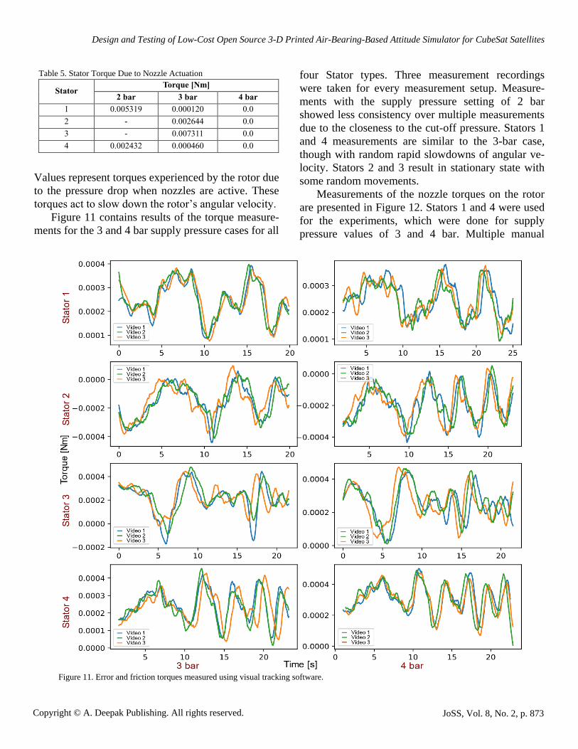
Values represent torques experienced by the rotor due
to the pressure drop when nozzles are active. These
torques act to slow down the rotor’s angular velocity.
Figure 11 contains results of the torque measure-
ments for the 3 and 4 bar supply pressure cases for all
four Stator types. Three measurement recordings
were taken for every measurement setup. Measure-
ments with the supply pressure setting of 2 bar
showed less consistency over multiple measurements
due to the closeness to the cut-off pressure. Stators 1
and 4 measurements are similar to the 3-bar case,
though with random rapid slowdowns of angular ve-
locity. Stators 2 and 3 result in stationary state with
some random movements.
Measurements of the nozzle torques on the rotor
are presented in Figure 12. Stators 1 and 4 were used
for the experiments, which were done for supply
pressure values of 3 and 4 bar. Multiple manual
Table 5. Stator Torque Due to Nozzle Actuation
Stator Torque [Nm]
2 bar 3 bar 4 bar
1 0.005319 0.000120 0.0
2 - 0.002644 0.0
3 - 0.007311 0.0
4 0.002432 0.000460 0.0
Figure 11. Error and friction torques measured using visual tracking software.

Jovanovic, N. et al.
Copyright © A. Deepak Publishing. All rights reserved. JoSS, Vol. 8, No. 2, p. 874
nozzle actuations, of durations of approximately 5 s
were taken in all four cases.
Figure 13 shows the nozzle’s measured force.
Vertical bars show standard deviations.
Discussion
Requirements for the air-bearing simulator plat-
form were defined earlier, and Requirements 1, 2,
and 4 were satisfied by the design. However, Re-
quirements 3 and 5 are needed to be evaluated only
after the platform experiments were performed. Op-
timization of Objective 1 aided in the design of the
rotor, while Objective 2 will be used during the eval-
uation of four competing stator designs.
Requirement 3 needs sufficient load capacity to
provide a frictionless environment to the rotor when
it contains the heaviest 1U CubeSat. The tests were
Figure 12. Nozzle torques measured using visual tracking software.
Figure 13. Nozzle force measured using measurement scale.

Design and Testing of Low-Cost Open Source 3-D Printed Air-Bearing-Based Attitude Simulator for CubeSat Satellites
Copyright © A. Deepak Publishing. All rights reserved. JoSS, Vol. 8, No. 2, p. 875
performed with a load heavier than the requirement
prescribed and in all cases the load lifting was
achievable with a supply pressure of 2 bar. However,
the tests of the nozzle actuation influence on the sta-
tor performance showed that the load capacity can
drop during the platform operation. Test results
showed that adding a margin of 2 bar and setting a
supply pressure to a value of 4 bar is enough to elim-
inate the issue. This is still under the maximum sup-
ply pressure of 5 bar prescribed by Requirement 6,
thus it can be considered that Requirement 3 holds.
Spherical air bearing used in Kim et al. (2001) with
the radius of 76.2 mm can lift 136 kg when supplied
with a pressure of 2 bar, while the platform in
Ustrzycki et al. (2011) of radius 31.75 mm has a load
capacity of 9.07 kg at 4.13 bar. Though sufficient, the
load capacity performance of the 3-D printed plat-
form is below commercially available platforms.
To minimize the error and friction torques, which
is needed for Objective 2, several stator types have
been designed and tested. Thermal images from Fig-
ure 10 reveal that pressure profiles of the stators are
not symmetrical. It is difficult to estimate the relative
differences between pressure intensities in different
socket areas from this results as the temperature-
pressure relation is not known and the possibility of
secondary temperature exchanges with environment.
Still, it is evident that the groove on the Stator 2 is
very effective for smoothing the pressure gradient.
Also, it is visible that higher number of orifices on
the Stators 3 and 4 provide smoother profiles than the
one from the stator 1. According to Table 4, Stator 2
provides the smallest mean torque values in both 3
and 4 bar cases, which is also apparent from the
longest revolution times. Comparing Stators 3 and 4
reveals that larger socket area can increase load ca-
pacity at the cost of increased error torque. Therefore,
error and friction torques would be minimized if Sta-
tor 2 is selected. Error torque measurement in (Wil-
cock, 1965) of a rotor with radius of 50.8 mm at 1.63
bar pressure and with a similar groove design on the
socket showed torques of orders thousand times less
than in the tests performed on the 3-D printed Stators.
Requirement 5 needs for the control torque to be
sufficiently strong to combat error, friction, and grav-
ity torques, while compensating for the parasitic
moments of inertia of the rotor. Error and friction
torque are summarized in Table 4 and maximum
torque values will be used for analysis. The worst
case scenario for the gravity torque can be calculated
with Eqn. (18), assuming the mass of 1.33 kg and 𝑟𝑐𝑚
equal to 10 mm with it lying inside a horizontal
plane. Then the gravity torque intensity is 0.130473
Nm. The torque compensation multiplier can be cal-
culated as inverse of K in Eqn. (16). For the satellite
with moments of inertia of 0.0022167 kg∙m2, the
multiplier is 2.08946. Assuming a need to decrease
angular velocity for 10°/s within period of 1 s, the
torque exerted by the satellite would be 0.000387
Nm. Therefore, the nozzles should provide 0.000422
Nm of additional torque to compensate for the
sphere’s moments of inertia. Combined torques need-
ed for error torque and parasitic moments of inertia
cancelation, taken with some margin, amount to
about 0.001 Nm, which can be easily supported with
the nozzles torques measured in all four cases shown
in Figure 12. However, there is little possibility left to
compensate for the gravity torque. Displacements of
the center of mass only of the order of micrometers
would be supported with the torque budget in this
analysis. Precise positioning of the satellite within the
rotor and adding of the balance masses remains nec-
essary, so that the gravity torque is not introduced.
Still, available gravity torque compensation can be
useful to reduce the efforts of fine tuning to some ex-
tent.
From Figure 11, dependency of the error torque
on the rotors orientation is clearly visible by compar-
ing multiple test runs, which is evident in all 8 test
setups. This means that it is possible to create a map
of error torques for a platform, which could be used
during the simulation to cancel them in real time.
Still, the nozzle torques proved variable over repeat-
ed actuations, which limits precise controllability of
the rotor. This variability is also evident from Figure
13. Another challenge is the similar order of the
magnitude for the error and satellite generated tor-
ques, which can significantly affect the simulation
performance if the error torque cancellation is imper-
fect. Improvements to the design are desirable to fur-
ther reduce error torque. Significant improvement is
expected with additional smoothing of the rotor’s sur-

Jovanovic, N. et al.
Copyright © A. Deepak Publishing. All rights reserved. JoSS, Vol. 8, No. 2, p. 876
face. Improving the nozzle torque stability can be
achieved by adding the pressure accumulator, to de-
couple them from the rest of the pressure distribution
system. However, nozzles require a different design
to enable the automation, and the possibility to con-
trol the exhaust force will be very helpful in stabiliz-
ing their response. Lastly, large losses in the pressure
distribution system were observed. Improving the
distribution effectiveness will enable higher nozzle
forces.
Design and measurements for the 1U CubeSat
platform are presented, though the attitude simulation
is needed for the larger CubeSat formats as well.
Scaling the platform to accommodate them necessi-
tates greater load capacities and stronger torques gen-
erated by the nozzles. Current design already showed
load capacity beyond the need of the 1U CubeSat,
though the larger rotor radius would directly improve
the load capacity. Therefore, load capacity is not ex-
pected to be a concern. However, increased rotor ra-
dius would drastically increase the parasitic moments
of inertia, as well. This, in turn, requires higher sup-
ply pressures, which is a safety concern. Still, the
larger rotor area would permit additional nozzles to
be distributed around the platform for additional
torque generation, thus lowering required pressures at
the points where 3-D printed parts are used.
Overall, the design was sufficient to provide near-
ly frictionless environment for the rotor, while show-
ing the possibility for torque cancelation and com-
pensation if nozzles get automated. The estimated
material cost of the platform is between 50 € and 100
€ (for ~550 g of PLA filament material, pneumatic
hoses and hose fittings), which is significantly less
expensive than commercial systems already in the
market. Providers of spherical air-bearings with pub-
lic prices of their products were not found. However,
on their tech blog (Physik Instrumente, 2015), Physik
Instrumente states that “PIglide air bearings with no
motors start at under $2000 (1,622 €) for a simple
linear air bearing slide bearings and under $3000
(2,433 €) for a small rotary bearing.” The retail prices
of the commercial system, which start at 24X the
costs of the system described here include labor
costs. Including labor costs may not always be ap-
propriate at universities, where for example building
the system is part of a course (Schelly et al., 2015;
Bailey et al., 2015). In labs where labor must be
funded, it is instructive to calculate the potential cost
of labor for the fabrication of the attitude simulator
system. The labor involved is represented by four
tasks: (1) 3-D printing; (2) finishing the prints; (3)
purchasing the non-printable components; and (4)
assembling the device when all of the components
have been gathered.
First, the 3-D printed components can be fabri-
cated on any FFF RepRap based 3-D printers and this
can now be considered a relatively low-skilled task
(Peterson and Pearce, 2017). The designs have al-
ready been made as part of this study and are easily
downloaded, pre-oriented and ready to be sent to a
pre-calibrated FFF based 3-D printer. There are hun-
dreds of thousands of these 3-D printers deployed
globally (Wohler, 2016), which are thus readily ac-
cessible to most labs. A tuned RepRap or a commer-
cial self-bed leveling open source 3-D printer (e.g. a
Lulzbot, Prusa or Ultimaker) can be left unattended
after the file has been sent to print (identical opera-
tion to the use of a 2-D printer or photocopying ma-
chine). Thus, the print time is not the labor time of
the individual operating the printer as the 3-D printer
does not need to be monitored by a user during print-
ing. So, although the actual 3-D print time is much
longer (approximately 115 hours in total for all prints
if single printer is used), the time that labor is focused
only on printing is less than half an hour to set up and
clear the print jobs. In addition, for labs without
ready access to a 3-D printer, one can accessed at Fab
Labs (Stacey, 2014; Fab Foundation), hackerspaces,
makerspaces, and even public libraries (e.g. in Fin-
land many libraries provide free 3-D printing facili-
ties that are sufficient for printing this project), as
well as using online 3-D printing services. After
printing, the parts need to be finished, which, again,
does not need to be highly-skilled labor. Next, pur-
chasing the components is a low-skill task. Regard-
less of the exact situation, this subtask can be under-
taken by the lowest-cost worker in an organization
and represents a trivial time investment. Finally, once
all of the components are gathered, they must be as-
sembled by a reasonably skilled individual research-
er.
Design and Testing of Low-Cost Open Source 3-D Printed Air-Bearing-Based Attitude Simulator for CubeSat Satellites
Copyright © A. Deepak Publishing. All rights reserved. JoSS, Vol. 8, No. 2, p. 877
Thus, the overall cost in labor to source, print,
finish and assemble the current platform design is
conservatively shorter than 30 hours. This indicates
that it is profitable for an organization to use the open
source version if their labor costs are under 80€/h.
Finally, a point should be made about the life cycle
cost advantages of the open source system. The air-
bearing simulator designs, with configurable parame-
ters, are open sourced and freely available in
OpenSCAD format. Thus, regardless of the cause of
the failure of the device it can be easily repaired from
readily available or 3-D printable components. This
ease of both repair and upgrade is not as readily
available for all of the commercial systems, which
would often demand the purchasing of a replacement
device or an expensive repair.
Finally, there are several possible improvements
to the platform and needed upgrades to enable auto-
mated operation. First, automated nozzles need to be
designed and manufactured. Visual tracking of the
rotor for the torque measurements can be used for
attitude tracking as well, though it requires adding of
real time torque calculation capabilities. To improve
its accuracy several options are available, including
the use of multiple cameras or addition of the mirrors
to have view of the rotor from several directions. Al-
so, it is possible to add an IMU or optical mouse sen-
sors to the platform. Finally, a routine for mapping of
the error torques poses a challenge of its own. It is of
great value to enable within the design easy position-
ing and balancing of the satellite in the rotor. The
open source nature of this design will enable anyone
with an interest in the air-bearing simulator platform
to make these improvements in the future.
Conclusions
An open source air-bearing simulator platform for
the 1U CubeSat satellite is designed and manufac-
tured. Several experiments are performed to charac-
terize its performance and usability for testing of real
satellites. To mitigate the problems caused by the im-
perfections in the fabrication process, the platform is
provided with the active torque generation via three
air nozzles. The results have shown that it is possible
to successfully remove the unwanted torques. Addi-
tionally, active torque generation allows to compen-
sate satellite generated torques for the parasitic mo-
ments of inertia of the platform. Removing the effects
of gravity torque proved to be unachievable with the
current design and future work has been identified for
a number of improvements to the design and details
for the further development of the platform.
Acknowledgements
This project was supported by Fulbright Finland
and Aalto ELEC Doctoral School.
References
Afrose, M. F., Masood, S. H., Nikzad, M. et al.
(2014): Effects of Build Orientations on Tensile
Properties of PLA Material Processed by FDM.
Adv. Materials Research, Vol. 1044, pp. 31–34.
Afrose, M. F., Masood, S. H., Iovenitti, P. et al.
(2016): Effects of Part Build Orientations on Fa-
tigue Behaviour of FDM-Processed PLA Materi-
al. Progress in Additive Manufacturing, Vol. 1
(1–2), pp. 21–28.
Bailey, M., Grieco, J., Speights, A. et al. (2015): 3D
Printing in the Classroom and Laboratory. J.
Comput. Sci. Coll. Vol. 31, pp. 183–184.
Bandyopadhyay, S., Foust, R., Subramanian, G. P. et
al. (2016): Review of Formation Flying and Con-
stellation Missions Using Nanosatellites. J. of
Spacecraft and Rockets, Vol. 53 (3), pp. 567–578.
Bouwmeester, J. and Guo, J. (2010): Survey of
Worldwide Pico- and Nanosatellite Missions,
Distributions and Subsystem Technology. Acta
Astronautica, Vol. 67 (7), pp. 854-862.
Bowyer A. (2014): 3D Printing and Humanity's First
Imperfect Replicator. 3D Printing and Additive
Manufacturing, Vol. 1 (1), pp. 4–5.
Boynton, R. (1996): Using A Spherical Air Bearing
to Simulate Weightlessness, presented at 55th
Annu. Conf. of the Soc. of Allied Weight Engi-
neers, Inc., Atlanta, Georgia, June 3–5, Paper
2297.

Jovanovic, N. et al.
Copyright © A. Deepak Publishing. All rights reserved. JoSS, Vol. 8, No. 2, p. 878
Brower, K., Puccinelli, R., Markin, C. J. et al. (2017):
An Open-Source, Programmable Pneumatic Set-
up for Operation and Automated Control of Sin-
gle-and Multi-Layer Microfluidic Devices.
HardwareX, Vol. 3, pp. 117–134.
Culton, E. A., King, J. R. and Monte Ward, P. E.
(2017): Design and Development of an Unre-
stricted Satellite Motion Simulator, presented at
the 31st Annu. AIAA/USU Conf. on Small Satel-
lites, Logan, Utah, August, Paper 22.
Dhankani, K. C. and Pearce, J. M. (2017): Open
Source Laboratory Sample Rotator Mixer and
Shaker. HardwareX, Vol. 1, pp. 1–12.
Doncaster, B., Williams, C. and Shulman, J. (2017):
Nano/Microsatellite Market Forecast, Space-
Works Enterprises, Inc.
ECSS-E-HB-32-26A. (2013): Spacecraft Mechanical
Loads Analysis Handbook. ECSS Secretariat
ESA-ESTEC Noordwijk.
Fab Foundation. “Fab Labs”. Available online:
http://www.fabfoundation.org/fab-labs/ (accessed
on Oct. 31, 2017).
Fernandez-Vicente, M., Calle, W., Ferrandiz, S. et al.
(2016): Effect of Infill Parameters on Tensile
Mechanical Behavior in Desktop 3D Printing. 3D
Printing and Additive Manufacturing, Vol. 3 (3),
pp. 183–192.
Fisher, D. K., and Gould, P. J. (2012): Open-Source
Hardware is a Low-Cost Alternative for Scientific
Instrumentation and Research. Modern Instru-
mentation, Vol. 1 (2), pp. 8–20.
Fortescue, P., Swinerd, G. and Stark, J. (2011):
Spacecraft Systems Engineering. Chichester, UK:
John Wiley & Sons.
G. Allan Smith. (1964): Dynamic Simulators for Test
of Space Vehicle Attitude Control Systems.
Hampton, Va: NASA – Langley Research Center.
Gavrilovich, I., Krut, S., Gouttefarde, M. et al.
(2014): Test Bench for Nanosatellite Attitude De-
termination and Control System Ground Tests,
presented at The 4S Symposium, Small Satellites
Systems and Services, Majorca, Spain, May 26–
30, 2014.
Gavrilovich, I., Krut, S., Gouttefarde, M. et al.
(2016): Innovative Approach to Use Air Bearings
in CubeSat Ground Tests, presented at The 4S
Symposium, Small Satellites Systems and Ser-
vices, Valletta, Malta, May 30–June 3, 2016.
Gibb, A. (2014): Building Open Source Hardware:
DIY Manufacturing for Hackers and Makers.
Pearson Education.
Guthrie, A. (1963): Vacuum Technology. New York:
Wiley.
Hamrock, B. J., Schmid, S. R., and Jacobson, B. O.
(2004): Fundamentals of Fluid Film Lubrication,
2nd ed. CRC Press.
Hou, Z. C., Lu, Y. N., Lao, Y. X. et al. (2009): A
New Trifilar Pendulum Approach to Identify All
Inertia Parameters of a Rigid Body or Assembly.
Mechanism and Machine Theory, Vol. 44 (6), pp.
1270–1280.
Jiang, J. and Claudel, C. (2017): A High Perfor-
mance, Low Power Computational Platform for
Complex Sensing Operations in Smart Cities.
HardwareX, Vol. 1, pp. 22–37.
Jones, R., Haufe, P., Sells, E., et al. (2011): RepRap -
The Replicating Rapid Prototyper. Robotica, Vol.
29 (1), pp. 177–191.
Karvinen, K., Tikka, T. and Praks, J. (2015): Using
Hobby Prototyping Boards and Commercial-Off-
the-Shelf (COTS) Components for Developing
Low-Cost, Fast-Delivery Satellite Subsystems. J.
of Small Satellites (JoSS), Vol. 4 (1), pp. 301–
314.
Kim, B., Velenis, E., Kriengsiri, P. et al. (2001): A
Spacecraft Simulator for Research and Education,
in Proc. AIAA/AAS Astrodynamics Specialists
Conf., No. 01-367, pp. 897–914.
Korr, A. L., and Hyer, P. (1962): A Trifilar Pendulum
for the Determination Moments of Inertia (No.
Fa-R-1653). Frankford Arsenal, Philadelphia:
Pitman-Dunn Research Labs.
Kwan, T. H., Lee, K. M. B., J. Yan et al. (2015): An
Air Bearing Table for Satellite Attitude Control
Simulation, in Proc. IEEE 10th Conf. on Indus-
trial Electronics and Applications (ICIEA), pp.
1420–1425.
Lanzotti, A., Grasso, M., Staiano, G. et al. (2015):
The Impact of Process Parameters on Mechanical
Properties of Parts Fabricated in PLA with an
Open-Source 3-D Printer. Rapid Prototyping J.,
Vol. 21 (5), pp. 604–617.
Design and Testing of Low-Cost Open Source 3-D Printed Air-Bearing-Based Attitude Simulator for CubeSat Satellites
Copyright © A. Deepak Publishing. All rights reserved. JoSS, Vol. 8, No. 2, p. 879
New Way Air Bearings. “Porous Media Technology”
(2009): Available at: http://www.newwayair
bearings.com/Porous-Media-Technology (accessed
Dec, 2017).
Palerm Serra, L., Barrera Ars, J., Salas Solanilla, J. et
al. (2014): Market Implications of Miniaturized
Satellites: High-Performance Microsats and the
Oversupply in Launchers' Attributes Set the Con-
ditions for Market Disruption. New Space, Vol. 2
(1), pp. 43–50.
Parker, K. (1984): The Importance of Thermal-
Vacuum Testing in Achieving High Reliability of
Spacecraft Mechanisms, in Proc. of the 18th Aer-
ospace Mech. Symp. NASA, Goddard Space
Flight Center, pp. 93–109.
Pearce, J. M. (2014): Laboratory Equipment: Cut
Costs with Open-Source Hardware. Nature, Vol.
505 (7485), pp. 618–618.
Pearce, J. M. (2015): Return on Investment for Open
Source Scientific Hardware Development. Sci-
ence and Public Policy, Vol. 43 (2), pp. 192–195.
Pearce, J. M. (2012): Building Research Equipment
with Free, Open-Source Hardware. Science, Vol.
337, pp. 1303–1304.
Pearce, J. M. (2013): Open-Source Lab: How to
Build Your Own Hardware and Reduce Research
Costs. Amsterdam: Elsevier.
Peck, M. A., Miller, L., Cavender, A. R. et al. (2003):
An Airbearing-Based Testbed for Momentum
Control Systems and Spacecraft Line of Sight.
Advances in the Astronautical Sciences, Vol. 114,
pp. 427–446.
Petersen, E. and Pearce, J. (2017): Emergence of
Home Manufacturing in the Developed World:
Return on Investment for Open-Source 3-D Print-
ers. Technologies, Vol. 5 (1), pp. 7–22.
Physik Instrumente. “Top 7 Air Bearing Myths”
(2015): Available at: http://www.pi-usa.us/blog/
top-7-air-bearing-myths/ (accessed Jan., 2018).
Pocero, L., Amaxilatis, D., Mylonas, G. et al. (2017):
Open Source IoT Meter Devices for Smart and
Energy-Efficient School Buildings. HardwareX,
Vol. 1, pp. 54–67.
Rakwal, D. and Bamberg, E. (2005): Design Guide-
lines for Spherical Aerostatic Bearings, in Proc.
2005 ASPE Conf., Norfolk, VA, Oct. 10–14, pp.
170–173.
Rankouhi, B., Javadpour, S., Delfanian, F. et al.
(2016): Failure Analysis and Mechanical Charac-
terization of 3D Printed ABS with Respect to
Layer Thickness and Orientation. J. of Failure
Analysis and Prevention, Vol. 16 (3), pp. 467–
481.
Rayna, T., and Striukova, L. (2016): From Rapid Pro-
totyping to Home Fabrication: How 3D Printing
is Changing Business Model Innovation. Techno-
logical Forecasting and Social Change, Vol. 102,
pp. 214–224.
Savitzky, A. and Golay, M. J. (1964). Smoothing and
Differentiation of Data by Simplified Least
Squares Procedures. Analytical Chemistry, Vol.
36 (8), pp. 1627–1639.
Schelly, C., Anzalone, G., Wijnen, B. et al. (2015):
Open-Source 3-D Printing Technologies for Edu-
cation: Bringing Additive Manufacturing to the
Classroom. J. of Visual Languages & Computing,
Vol. 28, pp. 226–237.
Schwartz J. L., and Hall C. D. (2004): System Identi-
fication of a Spherical Air-Bearing Spacecraft
Simulator, in Proc. AAS/AIAA Space Flight Me-
chanics Conf., Vol. 4, Paper 122.
Schwartz, L. J., Peck, A. M., and Hall D. C. (2003):
Historical Review of Air-Bearing Spacecraft
Simulators, J. of Guidance, Control, and Dynam-
ics, Vol. 26 (4), pp. 513–522.
Sells E., Smith Z., Bailard S., et al. (2010): RepRap:
The Replicating Rapid Prototyper: Maximizing
Customizability by Breeding the Means of Pro-
duction, in Handbook of Research in Mass Cus-
tomization and Personalization: Strategies and
Concepts, Piller, F. T., Tseng, M.M. (eds), World
Scientific, pp. 568–580.
Sidi. M.J. (1997): Spacecraft Dynamics and Control:
A Practical Engineering Approach. Cambridge
Aerospace Series: Cambridge University Press.
ISBN 9780521787802.
Stacey, M. (2014): The FAB LAB Network: A Glob-
al Platform for Digital Invention, Education and
Entrepreneurship. Innovations, Vol. 9, pp. 221–
238.

Jovanovic, N. et al.
Copyright © A. Deepak Publishing. All rights reserved. JoSS, Vol. 8, No. 2, p. 880
Tanaka, K., Tsuda, Y., Saiki, et al. (2011): The De-
velopment of the Spherical Aerostatic Bearings
for 3DRW, in Proc. 21th Workshop on JAXA As-
trodynamics and Flight Mechanics, Sagamihara,
Kanagawa Japan, Jul. 25–26, pp. 214–219.
Tymrak, B. M., Kreiger, M., and Pearce, J. M.
(2014): Mechanical Properties of Components
Fabricated with Open-Source 3-D Printers under
Realistic Environmental Conditions. Materials &
Design, Vol. 58, pp. 242–246.
Ustrzycki, T., Lee, R., and Chesser, H. (2011):
Spherical Air Bearing Attitude Control Simulator
for Nanosatellites, presented at the AIAA Model-
ing and Simulation Technologies Conf., Portland,
Oregon, Aug. 8–11, Paper 6272.
Verhoeven, C. J., Bentum, M. J., Monna, G. L. E. et
al. (2011): On the Origin of Satellite Swarms. Ac-
ta Astronautica, Vol. 68 (7), pp. 1392–1395.
Wilcock, D. F. (1965): Design and Performance of
Gas-Pressurized, Spherical, Space-Simulator
Bearings. J. of Basic Engineering, Vol. 87 (3),
pp. 604–612.
Wittbrodt, B., and Pearce, J. M. (2015): The Effects
of PLA Color on Material Properties of 3-D
Printed Components. Additive Manufacturing,
Vol. 8, pp. 110–116.
Woellert, K., Ehrenfreund, P., Ricco, A. J. et al.
(2011): Cubesats: Cost-Effective Science and
Technology Platforms for Emerging and Devel-
oping Nations. Advances in Space Research, Vol.
47 (4), pp. 663–684.
Wohler, T. (2016): Wohlers Report 2016. Wohlers
Assoc., Inc.
Woo, H., Perez, O. R., Chesi, S. et al. (2011): Cu-
beSat Three Axis Simulator(CubeTAS), present-
ed at the AIAA Modeling and Simulation Tech-
nologies Conf., Portland, Oregon, Aug. 8–11, Pa-
per 6271.
Wu, W., Geng, P., Li, G. et al. (2015): Influence of
Layer Thickness and Raster Angle on the Me-
chanical Properties of 3D-Printed PEEK and a
Comparative Mechanical Study between PEEK
and ABS. Materials, Vol. 8 (9), pp. 5834–5846.
Xia, X., Sun, G., Zhang, K. et al. (2017):
NanoSats/CubeSats ADCS Survey, in Proc. 29th
Chinese Control and Decision Conf. (CCDC),
IEEE, Chongqing, China, pp. 5151–5158.